EP3644697A1 - Kühlmodul für ein fahrzeug-steuergerät, fahrzeug-steuergerät mit einem kühlmodul und verfahren zur wasserkühlung eines fahrzeug-steuergeräts - Google Patents
Kühlmodul für ein fahrzeug-steuergerät, fahrzeug-steuergerät mit einem kühlmodul und verfahren zur wasserkühlung eines fahrzeug-steuergeräts Download PDFInfo
- Publication number
- EP3644697A1 EP3644697A1 EP19197158.9A EP19197158A EP3644697A1 EP 3644697 A1 EP3644697 A1 EP 3644697A1 EP 19197158 A EP19197158 A EP 19197158A EP 3644697 A1 EP3644697 A1 EP 3644697A1
- Authority
- EP
- European Patent Office
- Prior art keywords
- cooling
- bimetal
- vehicle control
- heat sink
- cooling fins
- Prior art date
- Legal status (The legal status is an assumption and is not a legal conclusion. Google has not performed a legal analysis and makes no representation as to the accuracy of the status listed.)
- Withdrawn
Links
- 238000001816 cooling Methods 0.000 title abstract description 117
- 238000000034 method Methods 0.000 title abstract description 15
- XLYOFNOQVPJJNP-UHFFFAOYSA-N water Substances O XLYOFNOQVPJJNP-UHFFFAOYSA-N 0.000 title abstract description 10
- 239000002826 coolant Substances 0.000 abstract description 33
- 230000001419 dependent effect Effects 0.000 abstract description 5
- LYCAIKOWRPUZTN-UHFFFAOYSA-N Ethylene glycol Chemical compound OCCO LYCAIKOWRPUZTN-UHFFFAOYSA-N 0.000 description 12
- 239000004020 conductor Substances 0.000 description 8
- 238000012546 transfer Methods 0.000 description 8
- 229910052751 metal Inorganic materials 0.000 description 7
- 239000002184 metal Substances 0.000 description 7
- 238000005452 bending Methods 0.000 description 6
- 150000002739 metals Chemical class 0.000 description 4
- 238000013473 artificial intelligence Methods 0.000 description 3
- AEDZKIACDBYJLQ-UHFFFAOYSA-N ethane-1,2-diol;hydrate Chemical compound O.OCCO AEDZKIACDBYJLQ-UHFFFAOYSA-N 0.000 description 3
- 239000000203 mixture Substances 0.000 description 3
- 102100034112 Alkyldihydroxyacetonephosphate synthase, peroxisomal Human genes 0.000 description 2
- RYGMFSIKBFXOCR-UHFFFAOYSA-N Copper Chemical compound [Cu] RYGMFSIKBFXOCR-UHFFFAOYSA-N 0.000 description 2
- 101000799143 Homo sapiens Alkyldihydroxyacetonephosphate synthase, peroxisomal Proteins 0.000 description 2
- 229910052782 aluminium Inorganic materials 0.000 description 2
- XAGFODPZIPBFFR-UHFFFAOYSA-N aluminium Chemical compound [Al] XAGFODPZIPBFFR-UHFFFAOYSA-N 0.000 description 2
- 238000000848 angular dependent Auger electron spectroscopy Methods 0.000 description 2
- 229910052802 copper Inorganic materials 0.000 description 2
- 239000010949 copper Substances 0.000 description 2
- 230000017525 heat dissipation Effects 0.000 description 2
- 239000004065 semiconductor Substances 0.000 description 2
- 238000003466 welding Methods 0.000 description 2
- 238000013528 artificial neural network Methods 0.000 description 1
- 230000002457 bidirectional effect Effects 0.000 description 1
- 239000012809 cooling fluid Substances 0.000 description 1
- 230000006735 deficit Effects 0.000 description 1
- 238000009795 derivation Methods 0.000 description 1
- 238000013461 design Methods 0.000 description 1
- 238000001514 detection method Methods 0.000 description 1
- 238000011161 development Methods 0.000 description 1
- 230000018109 developmental process Effects 0.000 description 1
- 238000000265 homogenisation Methods 0.000 description 1
- 238000009434 installation Methods 0.000 description 1
- 239000000463 material Substances 0.000 description 1
- 239000012528 membrane Substances 0.000 description 1
- 238000012856 packing Methods 0.000 description 1
- 238000012545 processing Methods 0.000 description 1
- 230000001105 regulatory effect Effects 0.000 description 1
- 238000005096 rolling process Methods 0.000 description 1
- 230000000930 thermomechanical effect Effects 0.000 description 1
- 238000002604 ultrasonography Methods 0.000 description 1
Images


Classifications
-
- H—ELECTRICITY
- H05—ELECTRIC TECHNIQUES NOT OTHERWISE PROVIDED FOR
- H05K—PRINTED CIRCUITS; CASINGS OR CONSTRUCTIONAL DETAILS OF ELECTRIC APPARATUS; MANUFACTURE OF ASSEMBLAGES OF ELECTRICAL COMPONENTS
- H05K7/00—Constructional details common to different types of electric apparatus
- H05K7/20—Modifications to facilitate cooling, ventilating, or heating
- H05K7/20845—Modifications to facilitate cooling, ventilating, or heating for automotive electronic casings
- H05K7/20872—Liquid coolant without phase change
-
- F—MECHANICAL ENGINEERING; LIGHTING; HEATING; WEAPONS; BLASTING
- F28—HEAT EXCHANGE IN GENERAL
- F28F—DETAILS OF HEAT-EXCHANGE AND HEAT-TRANSFER APPARATUS, OF GENERAL APPLICATION
- F28F13/00—Arrangements for modifying heat-transfer, e.g. increasing, decreasing
- F28F13/06—Arrangements for modifying heat-transfer, e.g. increasing, decreasing by affecting the pattern of flow of the heat-exchange media
- F28F13/08—Arrangements for modifying heat-transfer, e.g. increasing, decreasing by affecting the pattern of flow of the heat-exchange media by varying the cross-section of the flow channels
-
- G—PHYSICS
- G05—CONTROLLING; REGULATING
- G05D—SYSTEMS FOR CONTROLLING OR REGULATING NON-ELECTRIC VARIABLES
- G05D23/00—Control of temperature
- G05D23/01—Control of temperature without auxiliary power
- G05D23/02—Control of temperature without auxiliary power with sensing element expanding and contracting in response to changes of temperature
- G05D23/08—Control of temperature without auxiliary power with sensing element expanding and contracting in response to changes of temperature with bimetallic element
-
- H—ELECTRICITY
- H05—ELECTRIC TECHNIQUES NOT OTHERWISE PROVIDED FOR
- H05K—PRINTED CIRCUITS; CASINGS OR CONSTRUCTIONAL DETAILS OF ELECTRIC APPARATUS; MANUFACTURE OF ASSEMBLAGES OF ELECTRICAL COMPONENTS
- H05K7/00—Constructional details common to different types of electric apparatus
- H05K7/20—Modifications to facilitate cooling, ventilating, or heating
- H05K7/20218—Modifications to facilitate cooling, ventilating, or heating using a liquid coolant without phase change in electronic enclosures
- H05K7/20272—Accessories for moving fluid, for expanding fluid, for connecting fluid conduits, for distributing fluid, for removing gas or for preventing leakage, e.g. pumps, tanks or manifolds
-
- H—ELECTRICITY
- H05—ELECTRIC TECHNIQUES NOT OTHERWISE PROVIDED FOR
- H05K—PRINTED CIRCUITS; CASINGS OR CONSTRUCTIONAL DETAILS OF ELECTRIC APPARATUS; MANUFACTURE OF ASSEMBLAGES OF ELECTRICAL COMPONENTS
- H05K7/00—Constructional details common to different types of electric apparatus
- H05K7/20—Modifications to facilitate cooling, ventilating, or heating
- H05K7/20218—Modifications to facilitate cooling, ventilating, or heating using a liquid coolant without phase change in electronic enclosures
- H05K7/20281—Thermal management, e.g. liquid flow control
-
- F—MECHANICAL ENGINEERING; LIGHTING; HEATING; WEAPONS; BLASTING
- F01—MACHINES OR ENGINES IN GENERAL; ENGINE PLANTS IN GENERAL; STEAM ENGINES
- F01P—COOLING OF MACHINES OR ENGINES IN GENERAL; COOLING OF INTERNAL-COMBUSTION ENGINES
- F01P2050/00—Applications
- F01P2050/30—Circuit boards
-
- F—MECHANICAL ENGINEERING; LIGHTING; HEATING; WEAPONS; BLASTING
- F02—COMBUSTION ENGINES; HOT-GAS OR COMBUSTION-PRODUCT ENGINE PLANTS
- F02D—CONTROLLING COMBUSTION ENGINES
- F02D41/00—Electrical control of supply of combustible mixture or its constituents
- F02D41/20—Output circuits, e.g. for controlling currents in command coils
- F02D2041/202—Output circuits, e.g. for controlling currents in command coils characterised by the control of the circuit
- F02D2041/2065—Output circuits, e.g. for controlling currents in command coils characterised by the control of the circuit the control being related to the coil temperature
-
- F—MECHANICAL ENGINEERING; LIGHTING; HEATING; WEAPONS; BLASTING
- F28—HEAT EXCHANGE IN GENERAL
- F28F—DETAILS OF HEAT-EXCHANGE AND HEAT-TRANSFER APPARATUS, OF GENERAL APPLICATION
- F28F13/00—Arrangements for modifying heat-transfer, e.g. increasing, decreasing
- F28F2013/005—Thermal joints
- F28F2013/008—Variable conductance materials; Thermal switches
-
- F—MECHANICAL ENGINEERING; LIGHTING; HEATING; WEAPONS; BLASTING
- F28—HEAT EXCHANGE IN GENERAL
- F28F—DETAILS OF HEAT-EXCHANGE AND HEAT-TRANSFER APPARATUS, OF GENERAL APPLICATION
- F28F2255/00—Heat exchanger elements made of materials having special features or resulting from particular manufacturing processes
- F28F2255/04—Heat exchanger elements made of materials having special features or resulting from particular manufacturing processes comprising shape memory alloys or bimetallic elements
-
- G—PHYSICS
- G05—CONTROLLING; REGULATING
- G05D—SYSTEMS FOR CONTROLLING OR REGULATING NON-ELECTRIC VARIABLES
- G05D23/00—Control of temperature
- G05D23/19—Control of temperature characterised by the use of electric means
- G05D23/275—Control of temperature characterised by the use of electric means with sensing element expanding, contracting, or fusing in response to changes of temperature
- G05D23/27535—Details of the sensing element
- G05D23/2754—Details of the sensing element using bimetallic element
Definitions
- the invention relates to a cooling module for a vehicle control unit according to claim 1. Furthermore, the invention relates to a vehicle control unit according to claim 7 with a cooling module. In addition, the invention relates to a method according to claim 10 for water cooling a vehicle control unit.
- Vehicle control units in the English electronic control unit, abbreviated ECU, are also known from the prior art.
- Vehicle control units include hardware platforms for the logical processing of input signals in order to provide logic and / or power levels as regulating or control signals for vehicle control.
- vehicle control devices that regulate and control driver assistance systems and / or automated / autonomous driving comprise supercomputing hardware platforms.
- supercomputing platforms include multi-core processors comprising several central processor units and several graphics processors. In a multi-core processor, multiple cores are arranged on a single chip, that is to say a semiconductor component.
- Multi-core processors achieve higher computing power and are less expensive to implement in a chip compared to multi-processor systems, in which each individual core is arranged in a processor socket and the individual processor sockets are arranged on a motherboard.
- the multi-core processors process an artificial intelligence, for example artificial neural networks, in order to be able to react intuitively to new driving situations like a human driver. This is achieved using a large computing power. This creates a lot of heat that has to be dissipated by cooling. Because of its high specific heat capacity, water is a particularly suitable coolant for vehicle control units.
- a requirement for vehicle control units is functionality in the temperature range of essentially -40 ° C to + 9x ° C.
- water has a low suitability for cold.
- water is added to the coolant to add ethylene glycol reduce the volume fraction of ethylene glycol to an ice flake point of the water-ethylene glycol mixture.
- ethylene glycol volume fraction of over 50% is required.
- this high proportion of ethylene glycol leads to a high dependency between the temperature and viscosity of the coolant. As the temperature drops, especially below -10 ° C, the coolant becomes more viscous and the viscosity increases. This leads to an undesirable drop in volume flow and pressure increase.
- the cooling is not performant. Compensation of these fluid-mechanical parameters, volume flow and pressure, could be managed with a more powerful cooling pump. However, this would involve additional effort and costs.
- the invention has for its object to improve the cooling of vehicle control units.
- the invention solves this problem by a cooling module for a vehicle control device with the features of claim 1. Furthermore, the invention solves the problem by a vehicle control device with the features of claim 7. Furthermore, the invention solves the problem by a method for cooling a water Vehicle control unit having the features of claim 10.
- the cooling module according to the invention for a vehicle control unit comprises a heat sink. Furthermore, the cooling module comprises connections in order to conduct a coolant through the heat sink. In addition, the cooling module comprises a turbulence insert arranged in the heat sink. The turbulence insert comprises at least first cooling fins. The cooling module further comprises at least one first bimetal arranged in the heat sink. The bimetal is arranged to adjust the at least first cooling fins as a function of a temperature-dependent change in shape of the at least first bimetal.
- Cooling modules are structural units which consist of various components for cooling a device, for example a vehicle control unit, the components being dimensioned accordingly with regard to the devices to be cooled and the given installation space.
- the heat sink is 210 mm long and 140 mm wide.
- the ports are preferably an inlet and an outlet valve.
- the inlet valve is arranged on an inlet side of the heat sink.
- the outlet valve is arranged on an outlet side of the heat sink opposite the inlet side.
- the coolant flows through the heat sink essentially in a straight line.
- the inlet valve and outlet valve are arranged on one side of the heat sink. In this arrangement, the coolant flows through the heat sink essentially in a U-shape.
- the coolant is preferably a water-ethylene glycol mixture.
- Another component of the cooling module are the cooling fins to improve the heat transfer.
- the cooling fins or additional components of the cooling module form turbulence inserts for swirling the coolant.
- the cooling fins are made of metal, for example aluminum and / or copper.
- a bimetal comprises two metals with different coefficients of linear expansion.
- the two metals are bonded to one another in a material or form-fitting manner. If you connect the two ends of the two metals, for example by riveting, spot welding or rolling, the temperature-dependent different extension leads to a bending of the bimetal.
- the temperature-dependent bending of the bimetal and the contacting of the bimetal to the cooling fins results in the result that the bimetal serves as an actuator for the adjustment of the cooling fins.
- the bimetal together with the cooling fins acts like a membrane or a valve in relation to the coolant. At low temperatures, the bimetal bends and deforms the cooling fins.
- the bimetal presses the cooling fins in the direction of the housing wall of the heat sink.
- the valve is now open. At high temperatures, the bimetal takes on a straight, flat state. The cooling fins are essentially completely drawn into the passage channel of the coolant. The valve is now closed.
- the coolant flow is limited to a specified size.
- an essentially constant volume flow becomes constant Pressure loss in the heat sink over a temperature range of -40 ° C to + 9x ° C provided. This creates a dynamic turbulence insert that prevents the coolant from clumping together at low temperatures, in particular below -10 ° C. Overall, the cooling performance of the cooling module is improved by the bimetal.
- the bimetal has the particular advantage that it generates large forces.
- the relatively large masses of the cooling fins can thus be adjusted and at the same time the associated friction can be overcome.
- Another advantage of bimetal is its longevity due to its low-wear functionality and its suitability as a heat transfer medium.
- the bimetal is preferably contacted thermally on a housing edge of the heat sink in such a way that the thermal conductivity is as good as possible.
- This can be a metal to metal connection, preferably a welded-on solution.
- the heat flow not only runs through the cooling fluid, but also through the housing.
- the at least first cooling fins are preferably arranged transversely to the longitudinal direction of the heat sink.
- the central axis of the at least first bimetal is arranged parallel to the longitudinal direction of the heat sink. Both sides of the at least first bimetal are connected to the heat sink in addition to the central axis.
- a first end of each of the first cooling fins is connected to a first side or a second side of the heat sink opposite the first side.
- a second end of the first cooling fins is arranged on the first bimetal for adjusting the first cooling fins by bending the first bimetal as a function of temperature.
- the first side of the heat sink is preferably its underside.
- the second side of the heat sink is preferably the top thereof.
- the second end of the first cooling fins lies loosely on the first bimetal, slides on the first bimetal or is riveted or welded to the first bimetal, for example.
- the cooling module comprises second cooling fins.
- the second cooling fins are arranged transversely to the longitudinal direction of the heat sink.
- the cooling module comprises a second bimetal arranged in the cooling body.
- the second bimetal is arranged parallel to the first bimetal.
- a first end of each of the second cooling fins is connected to the second side or the first side of the heat sink.
- a second end of the second cooling fins is arranged on the second bimetal analogously to the first cooling fins, for adjusting the second cooling fins by bending the second bimetal as a function of temperature.
- the first cooling fins are connected to the underside of the heat sink, for example.
- the second cooling fins are connected to the top of the heat sink, for example.
- the first bimetal and the second bimetal preferably centered in the heat sink, are arranged between the first cooling fins and the second cooling fins. The volume flow of the coolant can thus be improved.
- the first bimetal bends in the opposite direction to the second bimetal. At low temperatures, the first bimetal, for example, presses the first cooling fins towards the bottom of the heat sink.
- the second bimetal for example, presses the second cooling fins towards the top of the heat sink at low temperatures.
- first cooling fins and / or the second cooling fins are each welded or riveted to the heat sink at their first end.
- the first cooling fins and / or the second cooling fins are preferably wave-shaped. This improves the swirling of the coolant and increases the surface area of the first cooling fins and / or the second cooling fins.
- the first bimetal and / or the second bimetal preferably have the shape of a sheet or are particularly preferably lamellar.
- the lamellar design improves the adjustability of the first cooling fins and / or the second cooling fins. This improves the cooling process.
- a vehicle control unit comprises a cooling module according to the invention.
- the vehicle control unit is preferably an AD / ADAS domain ECU with artificial intelligence, that is to say a vehicle control unit for driver assistance system, called advanced driver assistance systems in English, or for automated or autonomous driving functions, called automated or autonomous driving in English. Domain means that the vehicle control unit controls the entire area for ADAS / AD, in particular the environment detection by environment sensors such as camera, radar, lidar, ultrasound, microphones, the derivation of a real driving situation, the trajectory planning and the vehicle guidance.
- the hardware platform of the vehicle control unit is designed to process the input signals using artificial intelligence.
- the hardware platform includes in particular graphics processors that are designed for parallel computing, preferably in the form of multi-core processors.
- the cooling module is preferably flanged to the vehicle control unit in order to ensure heat transfer.
- a heat conductor for improving the heat transfer is advantageously between the vehicle control unit and the cooling module.
- the heat conductor is another component of the cooling module, for example.
- the heat conductor can be a so-called heat spreader, with the task of reducing the heat flow density over a larger area, for example from 23 x 23 mm area to a palm size.
- a heat spreader is a thermo-mechanical component, the special geometry of which reduces the heat flow density of a heat source to the heat sink by means of a heat-conductive body, for example comprising aluminum or copper. In the simplest case, this body is comparable to an upside-down pyramid.
- the heat source is on the lower tip and the heat sink is on the upper surface.
- the heat conductor is preferably riveted or welded to the first side of the heat sink.
- the first Cooling fins are also riveted or welded to the first side of the heat sink. By riveting or welding the heat conductor and the first cooling fins, the heat transfer is better than through a loosely sliding connection.
- the cooling module or the vehicle control unit are, for example, integrated in a cooling circuit of a vehicle, in which further vehicle components and / or further control units are also integrated.
- the cooling circuit is secured against failures by the turbulence insert with bimetal, which provides high-performance cooling without clumping of the coolant.
- the system availability is thus improved and impairment of the further vehicle components and / or further control devices is at least reduced.
- the cooling module and / or the vehicle control unit are preferably arranged in a housing.
- the housing protects the cooling module from mechanical stresses, weather influences and other external influences.
- the method achieves water cooling with an essentially constant volume flow and constant pressure loss in the temperature range from -40 ° C to + 9x ° C. A clumping of the coolant at low temperatures, especially below -10 ° C, is avoided.
- the cooling module 10 in Fig. 1 comprises a heat sink 11.
- the heat sink 11 has a first side 11a.
- the first side 11a is, for example, an underside of the heat sink 11, compare Fig. 3 .
- the heat sink 11 has a second side 11b.
- the second side 11b is, for example, an upper side of the heat sink 11, compare Fig. 3 .
- a coolant is passed through the heat sink 11.
- the coolant is, for example, a water-ethylene glycol mixture.
- the heat sink 11 forms, for example, channels through which the coolant is passed.
- a U-shaped channel is shown as an example.
- additional channels or protruding pins are alternatively attached for the targeted conduction of the coolant through the heat sink 11 or for homogenization of the coolant in the heat sink 11 Fig. 2
- the bidirectional arrows shown within the heat sink 11 clarify the direction of expansion of a first bimetal 14a and a second bimetal 14b between the respective riveted or welded end points thereof, see also Fig. 3 .
- the cooling module 10 comprises a first connection 12a. The coolant is conducted into the heat sink 11 via the first connection 12a.
- the first connection 12a is designed as an inlet valve.
- the cooling module 10 comprises a second connection 12b.
- the coolant is led out of the heat sink 11 via the second connection 12b.
- the second connection 12b is designed as an outlet valve.
- the cooling module 10 is flanged onto a vehicle control unit 20 in the figures, a heat conductor 15 being arranged between the cooling module 10 and the vehicle control unit 20.
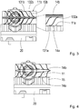
- Fig. 3 shows first cooling fins 13a and second cooling fins 13b.
- the first cooling fins 13a and the second cooling fins 13b are arranged one above the other and each have a wave or S shape, the shape of the second cooling fins 13b being mirrored vertically relative to the shape of the first cooling fins 13a.
- the first cooling fins 13a are welded to a first end 131a on the first side 11a of the heat sink 11, for example, and slide with a second end 132a on a first bimetal 14a.
- the second cooling fins 13b are, for example, welded to a first end 131b on the second side 11b of the heat sink 11 and slide with a second end 132b on a second bimetal 14b.
- first cooling fins 13a, second cooling fins 13b, the first bimetal 14a and the second bimetal 14b forms a valve due to the temperature-dependent bending of the first bimetal 14a and the second bimetal 14b.
- the valve is closed. This corresponds to the state at temperatures above a threshold.
- the valve is open. This corresponds to the condition at temperatures below the threshold.
- the threshold is -10 ° C.
- the heat transfer of the vehicle control unit 20 to the coolant via the heat conductor 15 takes place only via the first bimetal 14a and the first cooling fins 13a, but not via the second bimetal 14b with the second cooling fins 13b. At low temperatures, high-performance heat transfer is not yet required.
- Fig. 5 symbolizes the method according to the invention for water cooling the vehicle control unit 20.
- the coolant is passed through the cooling module 10.
- the cooling module 10 is in thermal contact with the vehicle control unit 20.
- a turbulent flow of the coolant through the cooling module 10 is generated by means of the turbulence insert.
- the volume flow of the coolant through the cooling module 10 is changed by the change in shape of the first bimetal 14a and the second bimetal 14b depending on the temperature.
Landscapes
- Engineering & Computer Science (AREA)
- Microelectronics & Electronic Packaging (AREA)
- Physics & Mathematics (AREA)
- Thermal Sciences (AREA)
- General Physics & Mathematics (AREA)
- Automation & Control Theory (AREA)
- Mechanical Engineering (AREA)
- General Engineering & Computer Science (AREA)
- Cooling Or The Like Of Semiconductors Or Solid State Devices (AREA)
- Cooling Or The Like Of Electrical Apparatus (AREA)
Abstract
Kühlmodul (10) für ein Fahrzeug-Steuergerät (20) umfassend einen Kühlkörper (11), Anschlüsse (12a, 12b), um ein Kühlmittel durch den Kühlkörper (11) zu leiten, eine in dem Kühlkörper (11) angeordnete Turbulenzeinlage umfassend wenigstens erste Kühlrippen (13a, 13b), und wenigstens ein erstes in dem Kühlkörper (11) angeordnetes Bimetall (14a, 14b), wobei das wenigstens erste Bimetall (14a, 14b) angeordnet ist, die wenigstens ersten Kühlrippen (13a, 13b) in Abhängigkeit einer Temperatur abhängigen Formveränderung des wenigstens ersten Bimetalls (14a, 14b) zu verstellen. Ferner bezieht sich die Erfindung auf ein Fahrzeug-Steuergerät (20) mit einem Kühlmodul (10) und ein Verfahren zur Wasserkühlung eines Fahrzeug-Steuergeräts (20).
Description
- Die Erfindung bezieht sich auf ein Kühlmodul für ein Fahrzeug-Steuergerät nach Anspruch 1. Ferner bezieht sich die Erfindung auf ein Fahrzeug-Steuergerät nach Anspruch 7 mit einem Kühlmodul. Außerdem bezieht sich die Erfindung auf ein Verfahren nach Anspruch 10 zur Wasserkühlung eines Fahrzeug-Steuergeräts.
- Aus dem Stand der Technik sind ferner Fahrzeug-Steuergeräte, im Englischen electronic control unit, abgekürzt ECU, bekannt. Fahrzeug-Steuergeräte umfassen Hardware-Plattformen zur logischen Verarbeitung von Eingangssignalen, um Logik- und/oder Leistungspegel als Regel-oder Steuersignale für die Fahrzeugsteuerung bereitzustellen. Fahrzeug-Steuergeräte, die Fahrerassistenzsysteme und/oder automatisiertes/autonomes Fahren regeln und steuern, umfassen im derzeitigen Stand der Technik supercomputing Hardware-Plattformen. Diese supercomputing Plattformen umfassen Mehrkernprozessoren umfassend mehrere zentrale Prozessoreinheiten und mehrere Grafikprozessoren. Bei einem Mehrkernprozessor sind mehrere Kerne auf einem einzigen Chip, das heißt einem Halbleiterbauelement, angeordnet. Mehrkernprozessoren erreichen eine höhere Rechenleistung und sind kostengünstiger in einem Chip zu implementieren im Vergleich zu Mehrprozessorsystemen, bei denen jeder einzelne Kern in einem Prozessorsockel angeordnet ist und die einzelnen Prozessorsockel auf einer Hauptplatine angeordnet sind. Die Mehrkernprozessoren prozessieren eine künstliche Intelligenz, zum Beispiel künstliche neuronale Netzwerke, um vorzugsweise intuitiv auf neue Fahrsituationen wie ein menschlicher Fahrer reagieren zu können. Dies wird realisiert mittels einer großen Rechenleistung. Dabei entsteht viel Wärme, die durch Kühlung abzuführen ist. Wasser ist wegen seiner hohen spezifischen Wärmekapazität ein besonders geeignetes Kühlmittel für Fahrzeug-Steuergeräte.
- Eine Anforderung an Fahrzeug-Steuergeräte ist eine Funktionalität im Temperaturbereich von im Wesentlichen -40°C bis +9x°C. Wasser hat aber eine geringe Kältetauglichkeit. In der Regel wird dem Kühlmittel Wasser Ethylenglykol zugesetzt, um in Abhängigkeit des Volumenanteils von Ethylenglykol einen Eisflockenpunkt des Wasser-Ethylenglykols-Gemisches herabzusetzen. Allerdings ist bei einer Temperatur von - 40°C hierfür ein Ethylenglykol Volumenanteil von über 50% erforderlich. Dieser hohe Ethylenglykol-Anteil führt jedoch nachteilig zu einer hohen Abhängigkeit zwischen Temperatur und Viskosität des Kühlmittels. Mit sinkender Temperatur, insbesondere unter -10 °C, wird das Kühlmittel dickflüssiger, die Viskosität nimmt zu. Dies führt zu einem unerwünschten Volumenstromabfall und Druckzunahme. Die Kühlung ist nicht performant. Eine Kompensation dieser fluidmechanischen Kenngrößen Volumenstrom und Druck wäre mit einer leistungsstärkeren Kühlpumpe zu bewältigen. Dies wäre jedoch mit zusätzlichem Aufwand und Kosten verbunden.
- Hier setzt die Erfindung an. Der Erfindung hat die Aufgabe zugrunde gelegen, die Kühlung von Fahrzeug-Steuergeräten zu verbessern.
- Die Erfindung löst diese Aufgabe durch ein Kühlmodul für ein Fahrzeug-Steuergerät mit den Merkmalen des Anspruchs 1. Ferner löst die Erfindung die Aufgabe durch ein Fahrzeug-Steuergerät mit den Merkmalen des Anspruchs 7. Außerdem löst die Erfindung die Aufgabe durch ein Verfahren zur Wasserkühlung eines Fahrzeug-Steuergeräts mit den Merkmalen des Anspruchs 10.
- Weiterbildungen und vorteilhafte Ausgestaltungen sind in den Unteransprüchen angegeben.
- Das erfindungsgemäße Kühlmodul für ein Fahrzeug-Steuergerät umfasst einen Kühlkörper. Ferner umfasst das Kühlmodul Anschlüsse, um ein Kühlmittel durch den Kühlkörper zu leiten. Außerdem umfasst das Kühlmodul eine in dem Kühlkörper angeordnete Turbulenzeinlage. Die Turbulenzeinlage umfasst wenigstens erste Kühlrippen. Das Kühlmodul umfasst des Weiteren wenigstens ein erstes in dem Kühlkörper angeordnetes Bimetall. Das Bimetall ist angeordnet, die wenigstens ersten Kühlrippen in Abhängigkeit einer Temperatur abhängigen Formveränderung des wenigstens ersten Bimetalls zu verstellen.
- Kühlmodule sind Baueinheiten, die aus verschiedenen Komponenten zur Kühlung eines Geräts, zum Beispiel eines Fahrzeug-Steuergeräts, bestehen, wobei die Komponenten hinsichtlich der zu kühlenden Geräte und des gegebenen Bauraums entsprechend dimensioniert sind. Zum Beispiel besitzt der Kühlkörper eine Länge von 210 mm und eine Breite von 140 mm. Die Anschlüsse sind vorzugsweise ein Einlass und ein Auslassventil. Das Einlassventil ist an einer Einlassseite des Kühlkörpers angeordnet. Das Auslassventil ist an einer der Einlassseite gegenüberliegende Auslassseite des Kühlkörpers angeordnet. Bei dieser Anordnung durchströmt das Kühlmittel den Kühlkörper im Wesentlichen geradlinig. Alternativ sind Einlassventil und Auslassventil an einer Seite des Kühlkörpers angeordnet. Bei dieser Anordnung durchströmt das Kühlmittel den Kühlkörper im Wesentlichen U-förmig. Das Kühlmittel ist vorzugsweise ein Wasser-Ethylenglykol-Gemisch. Eine weitere Komponente des Kühlmoduls sind die Kühlrippen zur Verbesserung des Wärmeübertrags. Die Kühlrippen oder zusätzliche Komponenten des Kühlmoduls bilden Turbulenzeinlagen zur Verwirbelung des Kühlmittels. Die Kühlrippen sind aus Metall, zum Beispiel Aluminium und/oder Kupfer.
- Ein Bimetall umfasst zwei Metalle mit unterschiedlichen Längenausdehnungskoeffizienten. Die zwei Metalle sind miteinander stoffschlüssig oder formschlüssig verbunden. Verbindet man die beiden Enden der zwei Metalle, zum Beispiel durch Nieten, punktuelles Schweißen oder Walzen, führt die Temperatur abhängige unterschiedliche Verlängerung zu einer Verbiegung des Bimetalls. Die Temperatur abhängige Verbiegung des Bimetalls und die Kontaktierung des Bimetalls an die Kühlrippen ergibt im Resultat, dass das Bimetall als Aktor für die Verstellung der Kühlrippen dient. Das Bimetall wirkt zusammen mit den Kühlrippen ähnlich einer Membran oder eines Ventils in Bezug auf das Kühlmittel. Bei niedrigen Temperaturen verbiegt sich das Bimetall und verformt die Kühlrippen. Insbesondere drückt das Bimetall die Kühlrippen in Richtung Gehäusewand des Kühlkörpers. Damit ist das Ventil offen. Bei hohen Temperaturen nimmt das Bimetall einen geradlinigen, ebenen Zustand ein. Die Kühlrippen werden im Wesentlichen vollständig in den Durchlasskanal des Kühlmittels gezogen. Damit ist das Ventil geschlossen. Die Strömung des Kühlmittels wird auf eine spezifizierte Größe begrenzt. Durch entsprechende Wahl der Metalle des Bimetalls wird ein im Wesentlichen konstanter Volumenstrom und konstanter Druckverlust in dem Kühlkörper über einen Temperaturbereich von -40°C bis +9x°C bereitgestellt. Damit wird eine dynamische Turbulenzeinlage realisiert, durch die ein Verklumpen des Kühlmittels bei tiefen Temperaturen, insbesondere unter -10°C, vermieden wird. Insgesamt wird durch das Bimetall die Kühlperformanz des Kühlmoduls verbessert. Das Bimetall hat insbesondere den Vorteil, dass es große Kräfte erzeugt. Die relativ großen Massen der Kühlrippen sind damit verstellbar und zugleich die damit verbundene Reibung überwindbar. Ein weiterer Vorteil des Bimetalls ist dessen Langlebigkeit aufgrund verschleißarmer Funktionsweise und dessen Eignung als Wärmeleitmedium. Das Bimetall wird vorzugsweise an einem Gehäuserand des Kühlkörpers derart thermisch ankontaktiert, dass die Wärmeleitfähigkeit möglichst gut ist. Dies kann eine Metall zu Metall Verbindung sein, vorzugsweise eine angeschweißte Lösung. So verläuft der Wärmestrom nicht nur durch das Kühlfluid, sondern auch über das Gehäuse.
- Vorzugsweise sind die wenigstens ersten Kühlrippen quer zu der Längsrichtung des Kühlkörpers angeordnet. Die Mittelachse des wenigstens ersten Bimetalls ist parallel zu der Längsrichtung des Kühlkörpers angeordnet. Beide Seiten des wenigstens ersten Bimetalls sind neben der Mittelachse mit dem Kühlkörper verbunden. Jeweils ein erstes Ende der ersten Kühlrippen ist mit einer ersten Seite oder einer der ersten Seite gegenüberliegender zweiter Seite des Kühlkörpers verbunden. Ein zweites Ende der ersten Kühlrippen ist an dem ersten Bimetall angeordnet zum Verstellen der ersten Kühlrippen durch temperaturabhängiges Verbiegen des ersten Bimetalls. Die erste Seite des Kühlkörpers ist vorzugsweise dessen Unterseite. Die zweite Seite des Kühlkörpers ist vorzugsweise dessen Oberseite. Das zweite Ende der ersten Kühlrippen liegt lose auf dem ersten Bimetall auf, gleitet auf dem ersten Bimetall oder ist mit dem ersten Bimetall zum Beispiel vernietet oder verschweißt. Mit dieser Anordnung ist es möglich, die Kühlrippen durch Verbiegen des Bimetalls einfach und mit hoher Präzision zu verstellen. Beispielsweise bewirkt eine Ausdehnung im Zehntelmillimeter-Bereich bis Millimeter-Bereich quer der Strömungsrichtung des Kühlmittels einen deutlich größeren Verstellweg in vertikaler Richtung, also in Richtung der Ober- bzw. Unterseite des Kühlkörpers.
- In einer weiteren Ausführung der Erfindung umfasst das Kühlmodul zweite Kühlrippen. Die zweiten Kühlrippen sind quer zu der Längsrichtung des Kühlkörpers angeordnet sind. Ferner umfasst das Kühlmodul ein zweites in dem Kühlkörper angeordnetes Bimetall. Das zweite Bimetall ist parallel zu dem ersten Bimetall angeordnet ist. Jeweils ein erstes Ende der zweiten Kühlrippen ist mit der zweiten Seite oder der ersten Seite des Kühlkörpers verbunden. Ein zweites Ende der zweiten Kühlrippen ist an dem zweiten Bimetall angeordnet analog zu den ersten Kühlrippen, zum Verstellen der zweiten Kühlrippen durch temperaturabhängiges Verbiegen des zweiten Bimetalls. Die ersten Kühlrippen sind beispielsweise mit der Unterseite des Kühlkörpers verbunden. Die zweiten Kühlrippen sind beispielsweise mit der Oberseite des Kühlkörpers verbunden. Zwischen den ersten Kühlrippen und den zweiten Kühlrippen sind das erste Bimetall und das zweite Bimetall, vorzugsweise zentriert im Kühlkörper, angeordnet. Damit kann der Volumenstrom des Kühlmittels verbessert werden.
- Das erste Bimetall verbiegt sich entgegengesetzt zu dem zweiten Bimetall. Bei tiefen Temperaturen drückt das erste Bimetall beispielsweise die ersten Kühlrippen in Richtung Unterseite des Kühlkörpers. Das zweite Bimetall drückt beispielsweise die zweiten Kühlrippen in Richtung Oberseite des Kühlkörpers bei tiefen Temperaturen.
- Vorteilhafterweise sind die ersten Kühlrippen und/oder die zweiten Kühlrippen jeweils an ihrem ersten Ende mit dem Kühlkörper verschweißt oder vernietet.
- Die ersten Kühlrippen und/oder die zweiten Kühlrippen sind bevorzugt wellenförmig ausgestaltet sind. Damit wird die Verwirbelung des Kühlmittels verbessert und die Oberfläche der ersten Kühlrippen und/oder der zweiten Kühlrippen vergrößert.
- Das erste Bimetall und/oder das zweite Bimetall besitzen bevorzugt die Form eines Bleches oder sind besonders bevorzugt lamellenförmig ausgestaltet. Die lamellenförmige Ausgestaltung verbessert die Verstellbarkeit der ersten Kühlrippen und/oder der zweiten Kühlrippen. Damit wird der Kühlvorgang verbessert.
- Erfindungsgemäß umfasst ein Fahrzeug-Steuergerät ein erfindungsgemäßes Kühlmodul. Das Fahrzeug-Steuergerät ist vorzugsweise eine AD/ADAS Domain ECU mit künstlicher Intelligenz, das heißt ein Fahrzeug-Steuergerät für Fahrerassistenzsystem, im Englischen advanced driver assistance systems genannt, oder für automatisierte oder autonome Fahrfunktionen, im Englischen automated or autonomous driving genannt. Domain bedeutet, dass das Fahrzeug-Steuergerät den gesamten Bereich für ADAS/AD steuert, insbesondere die Umfelderfassung durch Umfeldsensoren wie Kamera, Radar, Lidar, Ultraschall, Mikrofone, das Ableiten einer realen Fahrsituation, die Trajektorienplanung und die Fahrzeugführung. Die Hardware-Plattform des Fahrzeug-Steuergeräts ist ausgeführt, die Eingangssignale mittels künstlicher Intelligenz zu verarbeiten. Hierzu umfasst die Hardware-Plattform insbesondere Grafikprozessoren, die für parallel computing ausgelegt sind, vorzugsweise in Form von Mehrkernprozessoren.
- Das Kühlmodul ist vorzugsweise an das Fahrzeug-Steuergerät angeflanscht, um einen Wärmeübertrag sicherzustellen.
- Vorteilhafterweise ist zwischen dem Fahrzeug-Steuergerät und dem Kühlmodul ein Wärmeleiter zur Verbesserung des Wärmeübertrags. Der Wärmeleiter ist beispielsweise eine weitere Komponente des Kühlmoduls. Insbesondere kann der Wärmeleiter ein sogenannter Wärmespreizer sein, mit der Aufgabe die Wärmestromdichte über eine größere Fläche zu verkleinern, zum Beispiel von 23 x 23mm großen Fläche auf eine Handflächengroße. Ein Wärmespreizer ist ein thermo-mechanisches Bauteil, durch dessen spezielle Geometrie die Wärmestromdichte einer Wärmequelle zur Wärmesenke mittels eines wärmehochleitfähigen Körpers, zum Beispiel umfassend Aluminium oder Kupfer, reduziert wird. Im einfachsten Fall ist dieser Körper mit einer auf den Kopf gestellten Pyramide vergleichbar. Auf der unteren Spitze ist die Wärmequelle, auf der oberseitigen Fläche ist die Wärmesenke.
- Die Leistungsfähigkeit bei sogar größer werdender Packungsdichte von Halbleitern, insbesondere von GPUs, nimmt stetig zu, sodass mit konventionellen Kühlkonzepten eine adäquate Kühlung nicht mehr zu bewerkstelligen ist. Der Wärmeleiter ist vorzugsweise mit der ersten Seite des Kühlkörpers vernietet oder verschweißt. Die ersten Kühlrippen sind ebenfalls mit der ersten Seite des Kühlkörpers vernietet oder verschweißt. Durch das Vernieten oder Verschweißen des Wärmeleiters und der ersten Kühlrippen ist der Wärmeübergang besser als über eine lose schleifende Verbindung.
- Das Kühlmodul oder das Fahrzeug-Steuergerät sind beispielsweise in einem Kühlkreislauf eines Fahrzeuges integriert, in den auch weitere Fahrzeugkomponenten und/oder weitere Steuergeräte integriert sind. Durch die erfindungsgemäße Turbulenzeinlage mit Bimetall, die eine performante Kühlung ohne Verklumpen des Kühlmittels bereitstellt, wird der Kühlkreislauf gegen Ausfälle gesichert. Damit wird die Systemverfügbarkeit verbessert und eine Beeinträchtigung der weiteren Fahrzeugkomponenten und/oder weiteren Steuergeräte zumindest reduziert.
- Das Kühlmodul und/oder das Fahrzeug-Steuergerät sind vorzugsweise in einem Gehäuse angeordnet. Das Gehäuse schützt das Kühlmodul vor mechanischen Beanspruchungen, Wettereinflüssen und weiteren äußeren Einflüssen.
- Das erfindungsgemäße Verfahren zur Wasserkühlung eines Fahrzeug-Steuergeräts umfasst die Verfahrensschritte
- Leiten eines Kühlmittels durch ein Kühlmodul, wobei das Kühlmodul ein erfindungsgemäßes Kühlmodul ist und in Wärmekontakt mit dem Fahrzeug-Steuergerät ist,
- Erzeugen einer turbulenten Strömung des Kühlmittels durch das Kühlmodul mittels einer Turbulenzeinlage und
- Ändern des Volumenstroms des Kühlmittels durch das Kühlmodul.
- Mit dem Verfahren wird eine Wasserkühlung mit im Wesentlichen konstanten Volumenstrom und konstanten Druckverlust im Temperaturbereich von -40°C bis +9x°C erreicht. Eine Verklumpung des Kühlmittels bei tiefen Temperaturen, insbesondere unter -10°C, wird vermieden.
- Die Erfindung wird in den Ausführungsbeispielen verdeutlicht. Es zeigen:
-
Fig. 1 Querschnitt eines Ausführungsbeispiels eines erfindungsgemäßen Kühlmoduls, -
Fig. 2 das Ausführungsbeispiel derFig. 1 entlang der Schnittlinie I, -
Fig. 3 ein Ausführungsbeispiel eines erfindungsgemäßen Kühlmoduls in einer Grundstellung zweier Bimetalle, -
Fig. 4 das Ausführungsbeispiel derFig. 3 bei einer verbogenen Stellung der Bimetalle und -
Fig. 5 ein Ausführungsbeispiel eines erfindungsgemäßen Verfahrens. - In den Figuren bezeichnen gleiche Bezugszeichen gleiche oder funktionsähnliche Teile. Übersichthalber werden in den einzelnen Figuren nur die jeweils relevanten Teile hervorgehoben.
- Das Kühlmodul 10 in
Fig. 1 umfasst einen Kühlkörper 11. Der Kühlkörper 11 besitzt eine erste Seite 11a. Die erste Seite 11a ist beispielsweise eine Unterseite des Kühlkörpers 11, vergleicheFig. 3 . Ferner besitzt der Kühlkörper 11 eine zweite Seite 11b. Die zweite Seite 11b ist beispielsweise eine Oberseite des Kühlkörpers 11, vergleicheFig. 3 . Durch den Kühlkörper 11 wird ein Kühlmittel geleitet. Das Kühlmittel ist beispielsweise ein Wasser-Ethylenglykol-Gemisch. Der Kühlkörper 11 bildet beispielsweise Kanäle aus, durch die das Kühlmittel geleitet wird. - In
Fig. 2 ist exemplarisch ein U-förmiger Kanal dargestellt. Im Bereich des ersten Anschlusses 12a und/oder des zweiten Anschluss 12b sind alternativ zusätzliche Kanäle oder abstehende Zapfen angebracht zur zielgerichteten Leitung des Kühlmittels durch den Kühlkörper 11 oder zu Homogenisierung des Kühlmittels in dem Kühlkörper 11. Die inFig. 2 dargestellten bidirektionalen Pfeile innerhalb des Kühlkörpers 11 verdeutlichen die Ausdehnungsrichtung eines ersten Bimetalls 14a und eines zweiten Bimetalls 14b zwischen den jeweils fest vernieteten oder verschweißten Endpunkte derselben, siehe auchFig. 3 . Das Kühlmodul 10 umfasst einen ersten Anschluss 12a. Über den ersten Anschluss 12a wird das Kühlmittel in den Kühlkörper 11 geleitet. Der erste Anschluss 12a ist als ein Einlassventil ausgeführt. Das Kühlmodul 10 umfasst einen zweiten Anschluss 12b. Über den zweiten Anschluss 12b wird das Kühlmittel aus dem Kühlkörper 11 geleitet. Der zweite Anschluss 12b ist als ein Auslassventil ausgeführt. - Das Kühlmodul 10 ist in den Figuren auf ein Fahrzeug-Steuergerät 20 aufgeflanscht, wobei zwischen dem Kühlmodul 10 und dem Fahrzeug-Steuergerät 20 ein Wärmeleiter 15 angeordnet ist.
-
Fig. 3 zeigt erste Kühlrippen 13a und zweite Kühlrippen 13b. Die ersten Kühlrippen 13a und die zweiten Kühlrippen 13b sind übereinander angeordnet und besitzen jeweils eine Wellen- oder S-Form, wobei die Form der zweiten Kühlrippen 13b vertikal gespiegelt ist relativ zu der Form der ersten Kühlrippen 13a. Die ersten Kühlrippen 13a sind mit einem ersten Ende 131a an der ersten Seite 11a des Kühlkörpers 11 beispielsweise verschweißt und gleiten mit einem zweiten Ende 132a auf einem ersten Bimetall 14a. Die zweiten Kühlrippen 13b sind mit einem ersten Ende 131b an der zweiten Seite 11b des Kühlkörpers 11 beispielsweise verschweißt und gleiten mit einem zweiten Ende 132b auf einem zweiten Bimetall 14b. Die Anordnung der ersten Kühlrippen 13a, zweiten Kühlrippen 13b, des ersten Bimetalls 14a und des zweiten Bimetalls 14b bildet aufgrund der Temperatur abhängigen Verbiegung des ersten Bimetalls 14a und des zweiten Bimetalls 14b ein Ventil. InFig. 3 ist das Ventil geschlossen. Dies entspricht dem Zustand bei Temperaturen oberhalb eines Schwellenwertes. InFig. 4 ist das Ventil offen. Dies entspricht dem Zustand bei Temperaturen unterhalb des Schwellenwertes. Der Schwellenwert ist zum Beispiel -10°C. - Wenn das durch das erste Bimetall 14a und das zweite Bimetall 14b gebildete Ventil offen ist, siehe
Fig. 4 , erfolgt die Wärmeabfuhr des Fahrzeugsteuergeräts 20 an das Kühlmittel über den Wärmeleiter 15 nur über das erste Bimetall 14a und die ersten Kühlrippen 13a, nicht jedoch über das zweite Bimetall 14b mit den zweiten Kühlrippen 13b. Bei niedrigen Temperaturen wird noch kein hochperformanter Wärmeabtrag gefordert. - In
Fig. 3 . jedoch, wenn das erste Bimetall 14a und das zweite Bimetall 14b planarbündig gegenüberliegen, dann geschieht der Wärmeübergang zusätzlich auch von dem ersten Bimetall 14a an das direkt benachbarte zweite Bimetall 14b. Damit wird mehr Fläche für den Wärmeabtrag bereitgestellt und der Wärmeabtrag damit verbessert. -
Fig. 5 symbolisiert das erfindungsgemäße Verfahren zur Wasserkühlung des Fahrzeug-Steuergeräts 20. In einem ersten Verfahrensschritt V1 wird das Kühlmittel durch das Kühlmodul 10 geleitet. Das Kühlmodul 10 ist in Wärmekontakt mit dem Fahrzeug-Steuergerät 20. In einem zweiten Verfahrensschritt V2 wird eine turbulente Strömung des Kühlmittels durch das Kühlmodul 10 mittels der Turbulenzeinlage erzeugt. In einem dritten Verfahrensschritt V3 wird der Volumenstrom des Kühlmittels durch das Kühlmodul 10 durch die Formveränderung des ersten Bimetalls 14a und des zweiten Bimetalls 14b verändert in Abhängigkeit der Temperatur. -
- 10
- Kühlmodul
- 11
- Kühlkörper
- 11a
- erste Seite
- 11b
- zweite Seite
- 12a
- Anschluss
- 12b
- Anschluss
- 13a
- Kühlrippe
- 131a
- erstes Ende
- 132a
- zweites Ende
- 13b
- Kühlrippe
- 131b
- erstes Ende
- 132b
- zweites Ende
- 14a
- Bimetall
- 14b
- Bimetall
- 15
- Wärmeleiter
- 20
- Fahrzeug-Steuergerät
- L
- Längsrichtung
- V1-V3
- Verfahrensschritte
- I
- Schnittlinie
Claims (10)
- Kühlmodul (10) für ein Fahrzeug-Steuergerät (20) umfassend• einen Kühlkörper (11),• Anschlüsse (12a, 12b), um ein Kühlmittel durch den Kühlkörper (11) zu leiten,• eine in dem Kühlkörper (11) angeordnete Turbulenzeinlage umfassend wenigstens erste Kühlrippen (13a, 13b), und• wenigstens ein erstes in dem Kühlkörper (11) angeordnetes Bimetall (14a, 14b),wobei das wenigstens erste Bimetall (14a, 14b) angeordnet ist, die wenigstens ersten Kühlrippen (13a, 13b) in Abhängigkeit einer Temperatur abhängigen Formveränderung des wenigstens ersten Bimetalls (14a, 14b) zu verstellen.
- Kühlmodul (10) nach Anspruch 1, wobei• die wenigstens ersten Kühlrippen (13a, 13b) quer zu der Längsrichtung (L) des Kühlkörpers (11) angeordnet sind, und• die Mittelachse des wenigstens ersten Bimetalls (14a, 14b) parallel zu der Längsrichtung (L) des Kühlkörpers (11) angeordnet ist und beide Seiten des wenigstens ersten Bimetalls (14a, 14b) neben der Mittelachse mit dem Kühlkörper (11) verbunden sind,wobei jeweils ein erstes Ende (131a, 131b) der ersten Kühlrippen (13a, 13b) mit einer ersten Seite (11a) oder einer der ersten Seite (11a) gegenüberliegender zweiter Seite (11b) des Kühlkörpers (11) verbunden ist und ein zweites Ende (132a, 132b) der ersten Kühlrippen (13a, 13b) an dem ersten Bimetall (14a, 14b) angeordnet ist zum Verstellen der ersten Kühlrippen (13a, 13b) durch temperaturabhängiges Verbiegen des ersten Bimetalls (14a, 14b).
- Kühlmodul (10) nach Anspruch 1 oder 2, umfassend• zweite Kühlrippen (13b), die quer zu der Längsrichtung (L) des Kühlkörpers (11) angeordnet sind, und• ein zweites in dem Kühlkörper (11) angeordnetes Bimetall (14b), das parallel zu dem ersten Bimetall (14a) angeordnet ist,wobei jeweils ein erstes Ende (131b) der zweiten Kühlrippen (13b) mit der zweiten Seite (11b) oder der ersten Seite (11a) des Kühlkörpers (11) verbunden ist und ein zweites Ende (132b) der zweiten Kühlrippen (13b) an dem zweiten Bimetall (14b) angeordnet ist zum Verstellen der zweiten Kühlrippen (13b) durch temperaturabhängiges Verbiegen des zweiten Bimetalls (14b).
- Kühlmodul (10) nach einem der vorangehenden Ansprüche, wobei die die ersten Kühlrippen (13a) und/oder die zweiten Kühlrippen (13b) jeweils an ihrem ersten Ende 131a, 131b) mit dem Kühlkörper (11) verschweißt oder vernietet sind.
- Kühlmodul (10) nach einem der vorangehenden Ansprüche, wobei die ersten Kühlrippen (13a) und/oder die zweiten Kühlrippen (13b) wellenförmig ausgestaltet sind.
- Kühlmodul (10) nach einem der vorangehenden Ansprüche, wobei das erste Bimetall (14a) und/oder das zweite Bimetall (14b) die Form eines Bleches besitzt oder lamellenförmig ausgestaltet ist.
- Fahrzeug-Steuergerät (20) umfassend ein Kühlmodul (10) nach einem der Ansprüche 1 bis 6.
- Fahrzeug-Steuergerät (20) nach Anspruch 7, wobei das Kühlmodul (10) an das Fahrzeug-Steuergerät (20) angeflanscht ist.
- Fahrzeug-Steuergerät (20) nach Anspruch 7 oder 8, wobei zwischen dem Fahrzeug-Steuergerät (20) und dem Kühlmodul (10) ein Wärmeleiter (15) angeordnet ist.
- Verfahren zur Wasserkühlung eines Fahrzeug-Steuergeräts (20) umfassend die Verfahrensschritte• Leiten eines Kühlmittels durch ein Kühlmodul (10), wobei das Kühlmodul (10) ein Kühlmodul (10) nach einem der Ansprüche 1 bis 6 ist und in Wärmekontakt mit dem Fahrzeug-Steuergerät (20) ist (V1),• Erzeugen einer turbulenten Strömung des Kühlmittels durch das Kühlmodul (10) mittels der Turbulenzeinlage (V2) und• Ändern des Volumenstroms des Kühlmittels durch das Kühlmodul (10) (V3).
Applications Claiming Priority (1)
| Application Number | Priority Date | Filing Date | Title |
|---|---|---|---|
| DE102018218049.0A DE102018218049B4 (de) | 2018-10-22 | 2018-10-22 | Kühlmodul für ein Fahrzeug-Steuergerät, Fahrzeug-Steuergerät mit einem Kühlmodul und Verfahren zur Wasserkühlung eines Fahrzeug-Steuergeräts |
Publications (1)
| Publication Number | Publication Date |
|---|---|
| EP3644697A1 true EP3644697A1 (de) | 2020-04-29 |
Family
ID=67997338
Family Applications (1)
| Application Number | Title | Priority Date | Filing Date |
|---|---|---|---|
| EP19197158.9A Withdrawn EP3644697A1 (de) | 2018-10-22 | 2019-09-13 | Kühlmodul für ein fahrzeug-steuergerät, fahrzeug-steuergerät mit einem kühlmodul und verfahren zur wasserkühlung eines fahrzeug-steuergeräts |
Country Status (3)
| Country | Link |
|---|---|
| US (1) | US11209844B2 (de) |
| EP (1) | EP3644697A1 (de) |
| DE (1) | DE102018218049B4 (de) |
Families Citing this family (3)
| Publication number | Priority date | Publication date | Assignee | Title |
|---|---|---|---|---|
| EP4092720A1 (de) * | 2021-05-20 | 2022-11-23 | Aptiv Technologies Limited | Kühlkörper |
| DE102023211440A1 (de) * | 2023-11-17 | 2025-05-22 | Schaeffler Technologies AG & Co. KG | Leistungselektronik-Kühler, Leistungselektronikvorrichtung und Inverter |
| DE102024201708B3 (de) | 2024-02-23 | 2025-06-26 | Schaeffler Technologies AG & Co. KG | Elektronik-Kühler, Elektronikvorrichtung und Inverter mit einem Elektronik-Kühler |
Citations (3)
| Publication number | Priority date | Publication date | Assignee | Title |
|---|---|---|---|---|
| JPS5844755A (ja) * | 1981-09-11 | 1983-03-15 | Nec Corp | 強制空冷用ヒ−トシンク |
| EP3032580A1 (de) * | 2014-03-14 | 2016-06-15 | Fuji Electric Co., Ltd. | Kühlvorrichtung und halbleiterbauelement mit besagter kühlvorrichtung |
| DE102016106750A1 (de) * | 2015-04-15 | 2017-02-09 | Ford Global Technologies, Llc | Leistungswechselrichter für ein fahrzeug |
Family Cites Families (17)
| Publication number | Priority date | Publication date | Assignee | Title |
|---|---|---|---|---|
| US3513881A (en) * | 1967-07-24 | 1970-05-26 | Garrett Corp | Flow regulator having thrust recovery |
| CH524224A (de) * | 1970-11-18 | 1972-06-15 | Bbc Brown Boveri & Cie | Verfahren und Einrichtung zur Regelung der Durchflussmenge eines Fluides in einer Rohrleitung eines Kernkraftwerkes |
| US3831396A (en) * | 1971-08-19 | 1974-08-27 | Aeronautical Res Ass Of Prince | Self-regulating thermal protection system for heated surfaces |
| US6016250A (en) * | 1998-01-30 | 2000-01-18 | Credence Systems Corporation | Self-balancing thermal control device for integrated circuits |
| US6330157B1 (en) * | 1999-12-21 | 2001-12-11 | International Business Machines Corporation | Variable thermal exchanger and method thereof |
| US20020134542A1 (en) * | 2001-03-20 | 2002-09-26 | Unsworth John Duncan | Heat exchanger with passive in-line temperature control |
| DE112008000873T5 (de) * | 2007-05-28 | 2010-04-29 | Aisin Aw Co., Ltd. | Kühlvorrichtung für eine Steuereinheit für ein Automatikgetriebe |
| US20090321044A1 (en) * | 2008-06-30 | 2009-12-31 | Alcatel-Lucent Technologies Inc. | Active heat sink designs |
| CN104159436A (zh) * | 2014-08-15 | 2014-11-19 | 韩百萍 | 一种自清洁散热翅片散热器 |
| US10557671B2 (en) * | 2015-01-16 | 2020-02-11 | Hamilton Sundstrand Corporation | Self-regulating heat exchanger |
| DE102015007799A1 (de) * | 2015-06-19 | 2016-12-22 | Mann + Hummel Gmbh | Wärmeübertragerelement, Wärmeübertrager und Energiespeicher |
| US10267578B2 (en) * | 2015-08-04 | 2019-04-23 | Raytheon Company | Shape memory material based thermal coupler/decoupler and method |
| US9841772B2 (en) * | 2015-12-03 | 2017-12-12 | Te Connectivity Corporation | Temperature responsive thermal bridge |
| US11008943B2 (en) * | 2016-08-31 | 2021-05-18 | Unison Industries, Llc | Fan casing assembly with cooler and method of moving |
| US10004156B2 (en) * | 2016-09-26 | 2018-06-19 | Asia Vital Components Co., Ltd. | Heat radiation fin structure |
| US10730645B2 (en) * | 2017-04-21 | 2020-08-04 | The Boeing Company | System and method for shape memory alloy thermal interface |
| US10573575B2 (en) * | 2017-08-28 | 2020-02-25 | Intel Corporation | Semiconductor package with thermal fins |
-
2018
- 2018-10-22 DE DE102018218049.0A patent/DE102018218049B4/de active Active
-
2019
- 2019-09-13 EP EP19197158.9A patent/EP3644697A1/de not_active Withdrawn
- 2019-10-21 US US16/659,167 patent/US11209844B2/en active Active
Patent Citations (3)
| Publication number | Priority date | Publication date | Assignee | Title |
|---|---|---|---|---|
| JPS5844755A (ja) * | 1981-09-11 | 1983-03-15 | Nec Corp | 強制空冷用ヒ−トシンク |
| EP3032580A1 (de) * | 2014-03-14 | 2016-06-15 | Fuji Electric Co., Ltd. | Kühlvorrichtung und halbleiterbauelement mit besagter kühlvorrichtung |
| DE102016106750A1 (de) * | 2015-04-15 | 2017-02-09 | Ford Global Technologies, Llc | Leistungswechselrichter für ein fahrzeug |
Also Published As
| Publication number | Publication date |
|---|---|
| DE102018218049B4 (de) | 2020-08-13 |
| US20200128699A1 (en) | 2020-04-23 |
| US11209844B2 (en) | 2021-12-28 |
| DE102018218049A1 (de) | 2020-04-23 |
Similar Documents
| Publication | Publication Date | Title |
|---|---|---|
| EP3644697A1 (de) | Kühlmodul für ein fahrzeug-steuergerät, fahrzeug-steuergerät mit einem kühlmodul und verfahren zur wasserkühlung eines fahrzeug-steuergeräts | |
| DE112014004308T5 (de) | Flache Wärmetauschröhre sowie Wärmeträger-Heizvorrichtung und Klimatisierungseinrichtung für ein selbige nutzendes Fahrzeug | |
| DE112015006353T5 (de) | Kühlvorrichtung, leistungswandlervorrichtung und kühlsystem | |
| DE112022004158T5 (de) | Halbleitervorrichtung | |
| DE102017222350A1 (de) | Wärmetauscher für eine doppelseitige kühlung von elektronikmodulen | |
| DE112017003768T5 (de) | Kühlvorrichtung | |
| DE112018005305B4 (de) | Kühlkörperanordnung | |
| DE102021204769A1 (de) | Kühlvorrichtung | |
| DE102020207150A1 (de) | Vorrichtung für das wärmemanagement von elektronikbauteilen | |
| DE102005036299B4 (de) | Kühlanordnung | |
| EP2101351B1 (de) | Kühlvorrichtung zur Kühlung eines Bauteils | |
| DE112010001158B4 (de) | Heisswasserkühlvorrichtung | |
| WO2023051989A1 (de) | Kühler zum kühlen einer leistungselektronik | |
| DE112016006331T5 (de) | Halbleitervorrichtung | |
| DE102009010256A1 (de) | Leiterplatte mit Kühlkörper | |
| DE102021211544A1 (de) | Kühlrippe eines fluiddurchströmbaren Kühlers zum Kühlen einer Leistungselektronik | |
| DE102021204758A1 (de) | Kühlvorrichtung | |
| WO2024056378A1 (de) | Fluiddurchströmbarer kühler zum kühlen eines leistungsmoduls | |
| DE102006040187A1 (de) | Kühlvorrichtung, Kühlsystem und Kühlverfahren zur Kühlung von Bauelementen einer Leistungselektronik | |
| WO2023051990A1 (de) | Kühler zum kühlen einer leistungselektronik | |
| DE102015109976B4 (de) | Flüssigkeitsströmungskanal für verbesserte Wärmeübertragungseffizienz | |
| DE102018205568A1 (de) | Bauteil mit verbesserter Kühlleistung und Kraftfahrzeug mit zumindest einem Bauteil | |
| WO2023237352A1 (de) | Kühlvorrichtung zur kühlung von einer elektrischen und/oder elektronischen baugruppe | |
| DE102022209015A1 (de) | Fluiddurchströmbarer Kühler zum Kühlen einer Leistungselektronik | |
| DE102022205600B4 (de) | Kühlvorrichtung |
Legal Events
| Date | Code | Title | Description |
|---|---|---|---|
| PUAI | Public reference made under article 153(3) epc to a published international application that has entered the european phase |
Free format text: ORIGINAL CODE: 0009012 |
|
| STAA | Information on the status of an ep patent application or granted ep patent |
Free format text: STATUS: THE APPLICATION HAS BEEN PUBLISHED |
|
| AK | Designated contracting states |
Kind code of ref document: A1 Designated state(s): AL AT BE BG CH CY CZ DE DK EE ES FI FR GB GR HR HU IE IS IT LI LT LU LV MC MK MT NL NO PL PT RO RS SE SI SK SM TR |
|
| AX | Request for extension of the european patent |
Extension state: BA ME |
|
| 18D | Application deemed to be withdrawn |
Effective date: 20201030 |