EP3644523A1 - Procédé et dispositif pour rendre compte d'un état de canal dans un système de communication sans fil - Google Patents
Procédé et dispositif pour rendre compte d'un état de canal dans un système de communication sans fil Download PDFInfo
- Publication number
- EP3644523A1 EP3644523A1 EP18820435.8A EP18820435A EP3644523A1 EP 3644523 A1 EP3644523 A1 EP 3644523A1 EP 18820435 A EP18820435 A EP 18820435A EP 3644523 A1 EP3644523 A1 EP 3644523A1
- Authority
- EP
- European Patent Office
- Prior art keywords
- csi
- bwp
- measurement gap
- channel state
- measurement
- Prior art date
- Legal status (The legal status is an assumption and is not a legal conclusion. Google has not performed a legal analysis and makes no representation as to the accuracy of the status listed.)
- Pending
Links
Images


Classifications
-
- H—ELECTRICITY
- H04—ELECTRIC COMMUNICATION TECHNIQUE
- H04B—TRANSMISSION
- H04B7/00—Radio transmission systems, i.e. using radiation field
- H04B7/02—Diversity systems; Multi-antenna system, i.e. transmission or reception using multiple antennas
- H04B7/04—Diversity systems; Multi-antenna system, i.e. transmission or reception using multiple antennas using two or more spaced independent antennas
- H04B7/06—Diversity systems; Multi-antenna system, i.e. transmission or reception using multiple antennas using two or more spaced independent antennas at the transmitting station
- H04B7/0613—Diversity systems; Multi-antenna system, i.e. transmission or reception using multiple antennas using two or more spaced independent antennas at the transmitting station using simultaneous transmission
- H04B7/0615—Diversity systems; Multi-antenna system, i.e. transmission or reception using multiple antennas using two or more spaced independent antennas at the transmitting station using simultaneous transmission of weighted versions of same signal
- H04B7/0619—Diversity systems; Multi-antenna system, i.e. transmission or reception using multiple antennas using two or more spaced independent antennas at the transmitting station using simultaneous transmission of weighted versions of same signal using feedback from receiving side
- H04B7/0621—Feedback content
- H04B7/0626—Channel coefficients, e.g. channel state information [CSI]
-
- H—ELECTRICITY
- H04—ELECTRIC COMMUNICATION TECHNIQUE
- H04L—TRANSMISSION OF DIGITAL INFORMATION, e.g. TELEGRAPHIC COMMUNICATION
- H04L5/00—Arrangements affording multiple use of the transmission path
- H04L5/003—Arrangements for allocating sub-channels of the transmission path
- H04L5/0048—Allocation of pilot signals, i.e. of signals known to the receiver
-
- H—ELECTRICITY
- H04—ELECTRIC COMMUNICATION TECHNIQUE
- H04B—TRANSMISSION
- H04B17/00—Monitoring; Testing
- H04B17/20—Monitoring; Testing of receivers
- H04B17/24—Monitoring; Testing of receivers with feedback of measurements to the transmitter
-
- H—ELECTRICITY
- H04—ELECTRIC COMMUNICATION TECHNIQUE
- H04B—TRANSMISSION
- H04B7/00—Radio transmission systems, i.e. using radiation field
- H04B7/02—Diversity systems; Multi-antenna system, i.e. transmission or reception using multiple antennas
- H04B7/04—Diversity systems; Multi-antenna system, i.e. transmission or reception using multiple antennas using two or more spaced independent antennas
- H04B7/06—Diversity systems; Multi-antenna system, i.e. transmission or reception using multiple antennas using two or more spaced independent antennas at the transmitting station
-
- H—ELECTRICITY
- H04—ELECTRIC COMMUNICATION TECHNIQUE
- H04L—TRANSMISSION OF DIGITAL INFORMATION, e.g. TELEGRAPHIC COMMUNICATION
- H04L25/00—Baseband systems
- H04L25/02—Details ; arrangements for supplying electrical power along data transmission lines
- H04L25/0202—Channel estimation
Definitions
- the present disclosure relates to a wireless communication system, and more particularly, to a method for reporting a channel state and apparatus therefor.
- next-generation RAT considering enhanced mobile broadband communication (eMBB), massive MTC (mMTC), ultra-reliable and low latency communication (URLLC), etc. has been discussed.
- eMBB enhanced mobile broadband communication
- mMTC massive MTC
- URLLC ultra-reliable and low latency communication
- the technical task of the present disclosure is to propose a method for reporting a channel state.
- a method of reporting a channel state in a wireless communication system including receiving a channel state report configuration including an index of a first BandWidth Part (BWP), receiving a trigger of a channel state report not on the first BWP but on a second BWP, measuring the channel state on the second BWP in a measurement gap according to the trigger, and transmitting the measured channel state on an available uplink resource within a first activated BWP after the measurement gap to a base station.
- BWP BandWidth Part
- the method may further include receiving information related to the measurement gap from the base station, wherein the measurement gap is defined by a frequency resource within a slot, a period/slot offset, or a slot length.
- the measurement gap may include a first measurement gap after reception of the trigger among preset periodic or semi-persistent measurement gaps.
- the semi-persistent measurement gap may be enabled or disabled by signaling.
- the trigger of the channel state report on the second BWP may include a signaling for designating a measurement of the channel state within the measurement gap.
- the trigger of the channel state report on the second BWP may include downlink control information received in the measurement gap configured slot.
- the channel state report configuration may include a start RB index and an end RB index of the first BWP.
- a user equipment performing a channel state report in a wireless communication system
- the user equipment including a transmitter, a receiver, and a processor configured to control the transmitter and the receiver, wherein the processor is further configured to receive a channel state report configuration including an index of a first BandWidth Part (BWP), receive a trigger of a channel state report not on the first BWP but on a second BWP, measure the channel state on the second BWP in a measurement gap according to the trigger; and transmit the measured channel state on an available uplink resource within a first activated BWP after the measurement gap to a base station.
- BWP BandWidth Part
- the user equipment may further include receiving information related to the measurement gap from the base station, and the measurement gap may be defined by a frequency resource within a slot, a period/slot offset, or a slot length.
- the measurement gap may include a first measurement gap after reception of the trigger among preset periodic or semi-persistent measurement gaps.
- the semi-persistent measurement gap may be enabled or disabled by signaling.
- the trigger of the channel state report on the second BWP may include a signaling for designating a measurement of the channel state within the measurement gap.
- the trigger of the channel state report on the second BWP may include downlink control information received in the measurement gap configured slot.
- the channel state report configuration may include a start RB index and an end RB index of the first BWP.
- channel state reporting can be efficiently processed.
- a user equipment is fixed or mobile.
- the UE is a device that transmits and receives user data and/or control information by communicating with a base station (BS).
- BS base station
- the term 'UE' may be replaced with 'terminal equipment', 'Mobile Station (MS)', 'Mobile Terminal (MT)', 'User Terminal (UT)', 'Subscriber Station (SS)', 'wireless device', 'Personal Digital Assistant (PDA)', 'wireless modem', 'handheld device', etc.
- a BS is typically a fixed station that communicates with a UE and/or another BS. The BS exchanges data and control information with a UE and another BS.
- BS may be replaced with 'Advanced Base Station (ABS)', 'Node B', 'evolved-Node B (eNB)', 'Base Transceiver System (BTS)', 'Access Point (AP)', 'Processing Server (PS)', etc.
- ABS Advanced Base Station
- eNB 'Node B'
- BTS Base Transceiver System
- AP Access Point
- PS Processing Server
- a node refers to a fixed point capable of transmitting/receiving a radio signal to/from a UE by communication with the UE.
- Various eNBs can be used as nodes.
- a node can be a BS, NB, eNB, pico-cell eNB (PeNB), home eNB (HeNB), relay, repeater, etc.
- a node may not be an eNB.
- a node can be a radio remote head (RRH) or a radio remote unit (RRU). The RRH and RRU have power levels lower than that of the eNB.
- RRH radio remote head
- RRU radio remote unit
- RRH/RRU Since the RRH or RRU (referred to as RRH/RRU hereinafter) is connected to an eNB through a dedicated line such as an optical cable in general, cooperative communication according to RRH/RRU and eNB can be smoothly performed compared to cooperative communication according to eNBs connected through a wireless link.
- At least one antenna is installed per node.
- An antenna may refer to an antenna port, a virtual antenna or an antenna group.
- a node may also be called a point.
- Unlink a conventional centralized antenna system (CAS) (i.e. single node system) in which antennas are concentrated in an eNB and controlled an eNB controller, plural nodes are spaced apart at a predetermined distance or longer in a multi-node system.
- CAS centralized antenna system
- the plural nodes can be managed by one or more eNBs or eNB controllers that control operations of the nodes or schedule data to be transmitted/received through the nodes.
- Each node may be connected to an eNB or eNB controller managing the corresponding node via a cable or a dedicated line.
- the same cell identity (ID) or different cell IDs may be used for signal transmission/reception through plural nodes.
- each of the plural nodes operates as an antenna group of a cell. If nodes have different cell IDs in the multi-node system, the multi-node system can be regarded as a multi-cell (e.g.
- a network configured by multiple cells is called a multi-tier network.
- the cell ID of the RRH/RRU may be identical to or different from the cell ID of an eNB.
- both the RRH/RRU and eNB operate as independent eNBs.
- one or more eNBs or eNB controllers connected to plural nodes can control the plural nodes such that signals are simultaneously transmitted to or received from a UE through some or all nodes. While there is a difference between multi-node systems according to the nature of each node and implementation form of each node, multi-node systems are discriminated from single node systems (e.g. CAS, conventional MIMO systems, conventional relay systems, conventional repeater systems, etc.) since a plurality of nodes provides communication services to a UE in a predetermined time-frequency resource.
- single node systems e.g. CAS, conventional MIMO systems, conventional relay systems, conventional repeater systems, etc.
- a node refers to an antenna group spaced apart from another node by a predetermined distance or more, in general.
- embodiments of the present disclosure which will be described below, can even be applied to a case in which a node refers to an arbitrary antenna group irrespective of node interval.
- the embodiments of the preset disclosure are applicable on the assumption that the eNB controls a node composed of an H-pole antenna and a V-pole antenna.
- a communication scheme through which signals are transmitted/received via plural transmit (Tx)/receive (Rx) nodes, signals are transmitted/received via at least one node selected from plural Tx/Rx nodes, or a node transmitting a downlink signal is discriminated from a node transmitting an uplink signal is called multi-eNB MIMO or CoMP (Coordinated Multi-Point Tx/Rx).
- CoMP Coordinated Multi-Point Tx/Rx.
- Coordinated transmission schemes from among CoMP communication schemes can be categorized into JP (Joint Processing) and scheduling coordination.
- the former may be divided into JT (Joint Transmission)/JR (Joint Reception) and DPS (Dynamic Point Selection) and the latter may be divided into CS (Coordinated Scheduling) and CB (Coordinated Beamforming). DPS may be called DCS (Dynamic Cell Selection).
- JP Joint Transmission
- JR Joint Reception
- DCS Coordinatd Beamforming
- DPS refers to a communication scheme by which a signal is transmitted/received through a node selected from plural nodes according to a specific rule.
- signal transmission reliability can be improved because a node having a good channel state between the node and a UE is selected as a communication node.
- a cell refers to a specific geographical area in which one or more nodes provide communication services. Accordingly, communication with a specific cell may mean communication with an eNB or a node providing communication services to the specific cell.
- a downlink/uplink signal of a specific cell refers to a downlink/uplink signal from/to an eNB or a node providing communication services to the specific cell.
- a cell providing uplink/downlink communication services to a UE is called a serving cell.
- channel status/quality of a specific cell refers to channel status/quality of a channel or a communication link generated between an eNB or a node providing communication services to the specific cell and a UE.
- a UE can measure downlink channel state from a specific node using one or more CSI-RSs (Channel State Information Reference Signals) transmitted through antenna port(s) of the specific node on a CSI-RS resource allocated to the specific node.
- CSI-RSs Channel State Information Reference Signals
- neighboring nodes transmit CSI-RS resources on orthogonal CSI-RS resources.
- CSI-RS resources are orthogonal, this means that the CSI-RS resources have different subframe configurations and/or CSI-RS sequences which specify subframes to which CSI-RSs are allocated according to CSI-RS resource configurations, subframe offsets and transmission periods, etc. which specify symbols and subcarriers carrying the CSI RSs.
- PDCCH Physical Downlink Control Channel
- PCFICH Physical Control Format Indicator Channel
- PHICH Physical Hybrid automatic repeat request Indicator Channel
- PDSCH Physical Downlink Shared Channel
- PUCCH Physical Uplink Control Channel
- PUSCH Physical Uplink Shared Channel
- PRACH Physical Random Access Channel
- a time-frequency resource or a resource element (RE) which is allocated to or belongs to PDCCH/PCFICH/PHICH/PDSCH/PUCCH/PUSCH/PRACH, is referred to as a PDCCH/PCFICH/PHICH/PDSCH/PUCCH/PUSCH/PRACH RE or PDCCH/PCFICH/PHICH/PDSCH/PUCCH/PUSCH/PRACH resource.
- transmission of PUCCH/PUSCH/PRACH by a UE is equivalent to transmission of uplink control information/uplink data/random access signal through or on PUCCH/PUSCH/PRACH.
- transmission of PDCCH/PCFICH/PHICH/PDSCH by an eNB is equivalent to transmission of downlink data/control information through or on PDCCH/PCFICH/PHICH/PDSCH.
- FIG. 1 illustrates an exemplary radio frame structure used in a wireless communication system.
- FIG. 1(a) illustrates a frame structure for frequency division duplex (FDD) used in 3GPP LTE/LTE-A and
- FIG. 1(b) illustrates a frame structure for time division duplex (TDD) used in 3GPP LTE/LTE-A.
- FDD frequency division duplex
- TDD time division duplex
- a radio frame used in 3GPP LTE/LTE-A has a length of 10ms (307200Ts) and includes 10 subframes in equal size.
- the 10 subframes in the radio frame may be numbered.
- Each subframe has a length of 1ms and includes two slots.
- 20 slots in the radio frame can be sequentially numbered from 0 to 19.
- Each slot has a length of 0.5ms.
- a time for transmitting a subframe is defined as a transmission time interval (TTI).
- Time resources can be discriminated by a radio frame number (or radio frame index), subframe number (or subframe index) and a slot number (or slot index).
- the radio frame can be configured differently according to duplex mode. Downlink transmission is discriminated from uplink transmission by frequency in FDD mode, and thus the radio frame includes only one of a downlink subframe and an uplink subframe in a specific frequency band. In TDD mode, downlink transmission is discriminated from uplink transmission by time, and thus the radio frame includes both a downlink subframe and an uplink subframe in a specific frequency band.
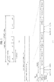
- Table 1 shows DL-UL configurations of subframes in a radio frame in the TDD mode.
- Table 1 DL-UL configuration Downlink-to-Uplink Switch-point periodicity Subframe number 0 1 2 3 4 5 6 7 8 9 0 5ms D S U U U D S U U U 1 5ms D S U U D D S U U D 2 5ms D S U D D D S U D D 3 10ms D S U U U D D D D D D 4 10ms D S U U D D D D D D 5 10ms D S U D D D D D D D 6 5ms D S U U U U D S U U D S U U D S U U D
- D denotes a downlink subframe
- U denotes an uplink subframe
- S denotes a special subframe.
- the special subframe includes three fields of DwPTS (Downlink Pilot TimeSlot), GP (Guard Period), and UpPTS (Uplink Pilot TimeSlot).
- DwPTS is a period reserved for downlink transmission
- UpPTS is a period reserved for uplink transmission.
- Table 2 shows special subframe configuration.
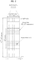
- FIG. 2 illustrates an exemplary downlink/uplink slot structure in a wireless communication system. Particularly, FIG. 2 illustrates a resource grid structure in 3GPP LTE/LTE-A. A resource grid is present per antenna port.
- a slot includes a plurality of OFDM (Orthogonal Frequency Division Multiplexing) symbols in the time domain and a plurality of resource blocks (RBs) in the frequency domain.
- An OFDM symbol may refer to a symbol period.
- a signal transmitted in each slot may be represented by a resource grid composed of N RB DL / UL ⁇ N sc RB subcarriers and N symb DL / UL OFDM symbols.
- N RB DL denotes the number of RBs in a downlink slot
- N RB UL denotes the number of RBs in an uplink slot.
- N RB DL and N RB UL respectively depend on a DL transmission bandwidth and a UL transmission bandwidth.
- N symb DL denotes the number of OFDM symbols in the downlink slot and N symb UL denotes the number of OFDM symbols in the uplink slot.
- N sc RB denotes the number of subcarriers constructing one RB.
- An OFDM symbol may be called an SC-FDM (Single Carrier Frequency Division Multiplexing) symbol according to multiple access scheme.
- the number of OFDM symbols included in a slot may depend on a channel bandwidth and the length of a cyclic prefix (CP).
- CP cyclic prefix
- a slot includes 7 OFDM symbols in the case of normal CP and 6 OFDM symbols in the case of extended CP.
- FIG. 2 illustrates a subframe in which a slot includes 7 OFDM symbols for convenience, embodiments of the present disclosure can be equally applied to subframes having different numbers of OFDM symbols.
- each OFDM symbol includes N RB DL / UL ⁇ N sc RB subcarriers in the frequency domain.
- Subcarrier types can be classified into a data subcarrier for data transmission, a reference signal subcarrier for reference signal transmission, and null subcarriers for a guard band and a direct current (DC) component.
- the null subcarrier for a DC component is a subcarrier remaining unused and is mapped to a carrier frequency (f0) during OFDM signal generation or frequency up-conversion.
- the carrier frequency is also called a center frequency.
- An RB is defined by N symb DL / UL (e.g. 7) consecutive OFDM symbols in the time domain and N sc RB (e.g. 12) consecutive subcarriers in the frequency domain.
- N symb DL / UL e.g. 7
- N sc RB e.g. 12
- a resource composed by an OFDM symbol and a subcarrier is called a resource element (RE) or a tone.
- an RB is composed of N symb DL / UL ⁇ N sc RB REs.
- Each RE in a resource grid can be uniquely defined by an index pair (k, l) in a slot.
- k is an index in the range of 0 to N symb DL / UL ⁇ N sc RB ⁇ 1 in the frequency domain and 1 is an index in the range of 0 to N symb DL / UL ⁇ 1 .
- a physical resource block (PRB) pair Two RBs that occupy N sc RB consecutive subcarriers in a subframe and respectively disposed in two slots of the subframe are called a physical resource block (PRB) pair. Two RBs constituting a PRB pair have the same PRB number (or PRB index).
- a virtual resource block (VRB) is a logical resource allocation unit for resource allocation. The VRB has the same size as that of the PRB.
- the VRB may be divided into a localized VRB and a distributed VRB depending on a mapping scheme of VRB into PRB.
- N VRB DL N RB DL is obtained. Accordingly, according to the localized mapping scheme, the VRBs having the same VRB number are mapped into the PRBs having the same PRB number at the first slot and the second slot. On the other hand, the distributed VRBs are mapped into the PRBs through interleaving. Accordingly, the VRBs having the same VRB number may be mapped into the PRBs having different PRB numbers at the first slot and the second slot. Two PRBs, which are respectively located at two slots of the subframe and have the same VRB number, will be referred to as a pair of VRBs.
- FIG. 3 illustrates a downlink (DL) subframe structure used in 3GPP LTE/LTE-A.
- a DL subframe is divided into a control region and a data region.
- a maximum of three (four) OFDM symbols located in a front portion of a first slot within a subframe correspond to the control region to which a control channel is allocated.
- a resource region available for PDCCH transmission in the DL subframe is referred to as a PDCCH region hereinafter.
- the remaining OFDM symbols correspond to the data region to which a physical downlink shared chancel (PDSCH) is allocated.
- PDSCH physical downlink shared chancel
- a resource region available for PDSCH transmission in the DL subframe is referred to as a PDSCH region hereinafter.
- Examples of downlink control channels used in 3GPP LTE include a physical control format indicator channel (PCFICH), a physical downlink control channel (PDCCH), a physical hybrid ARQ indicator channel (PHICH), etc.
- the PCFICH is transmitted at a first OFDM symbol of a subframe and carries information regarding the number of OFDM symbols used for transmission of control channels within the subframe.
- the PHICH is a response of uplink transmission and carries an HARQ acknowledgment (ACK)/negative acknowledgment (NACK) signal.
- ACK HARQ acknowledgment
- NACK negative acknowledgment
- the DCI contains resource allocation information and control information for a UE or a UE group.
- the DCI includes a transport format and resource allocation information of a downlink shared channel (DL-SCH), a transport format and resource allocation information of an uplink shared channel (UL-SCH), paging information of a paging channel (PCH), system information on the DL-SCH, information about resource allocation of an upper layer control message such as a random access response transmitted on the PDSCH, a transmit control command set with respect to individual UEs in a UE group, a transmit power control command, information on activation of a voice over IP (VoIP), downlink assignment index (DAI), etc.
- DL-SCH downlink shared channel
- UL-SCH uplink shared channel
- PCH paging information of a paging channel
- system information on the DL-SCH information about resource allocation of an upper layer control message such as a random access response transmitted on the PDSCH
- the transport format and resource allocation information of the DL-SCH are also called DL scheduling information or a DL grant and the transport format and resource allocation information of the UL-SCH are also called UL scheduling information or a UL grant.
- the size and purpose of DCI carried on a PDCCH depend on DCI format and the size thereof may be varied according to coding rate.
- Control information such as a hopping flag, information on RB allocation, modulation coding scheme (MCS), redundancy version (RV), new data indicator (NDI), information on transmit power control (TPC), cyclic shift demodulation reference signal (DMRS), UL index, channel quality information (CQI) request, DL assignment index, HARQ process number, transmitted precoding matrix indicator (TPMI), precoding matrix indicator (PMI), etc. is selected and combined based on DCI format and transmitted to a UE as DCI.
- MCS modulation coding scheme
- RV redundancy version
- NDI new data indicator
- TPC transmit power control
- DMRS cyclic shift demodulation reference signal
- CQI channel quality information
- TPMI transmitted precoding matrix indicator
- PMI precoding matrix indicator
- a DCI format for a UE depends on transmission mode (TM) set for the UE.
- TM transmission mode
- only a DCI format corresponding to a specific TM can be used for a UE configured in the specific TM.
- a PDCCH is transmitted on an aggregation of one or several consecutive control channel elements (CCEs).
- the CCE is a logical allocation unit used to provide the PDCCH with a coding rate based on a state of a radio channel.
- the CCE corresponds to a plurality of resource element groups (REGs). For example, a CCE corresponds to 9 REGs and an REG corresponds to 4 REs.
- 3GPP LTE defines a CCE set in which a PDCCH can be located for each UE.
- a CCE set from which a UE can detect a PDCCH thereof is called a PDCCH search space, simply, search space.
- An individual resource through which the PDCCH can be transmitted within the search space is called a PDCCH candidate.
- search spaces for DCI formats may have different sizes and include a dedicated search space and a common search space.
- the dedicated search space is a UE-specific search space and is configured for each UE.
- the common search space is configured for a plurality of UEs. Aggregation levels defining the search space is as follows. [Table 3] Type Size [in CCEs] UE-specific 1 6 6 2 12 6 4 8 2 8 16 2 Common 4 16 4 8 16 2
- a PDCCH candidate corresponds to 1, 2, 4 or 8 CCEs according to CCE aggregation level.
- An eNB transmits a PDCCH (DCI) on an arbitrary PDCCH candidate with in a search space and a UE monitors the search space to detect the PDCCH (DCI).
- monitoring refers to attempting to decode each PDCCH in the corresponding search space according to all monitored DCI formats.
- the UE can detect the PDCCH thereof by monitoring plural PDCCHs. Since the UE does not know the position in which the PDCCH thereof is transmitted, the UE attempts to decode all PDCCHs of the corresponding DCI format for each subframe until a PDCCH having the ID thereof is detected. This process is called blind detection (or blind decoding (BD)).
- BD blind decoding
- the eNB can transmit data for a UE or a UE group through the data region.
- Data transmitted through the data region may be called user data.
- a physical downlink shared channel (PDSCH) may be allocated to the data region.
- a paging channel (PCH) and downlink-shared channel (DL-SCH) are transmitted through the PDSCH.
- the UE can read data transmitted through the PDSCH by decoding control information transmitted through a PDCCH.
- Information representing a UE or a UE group to which data on the PDSCH is transmitted, how the UE or UE group receives and decodes the PDSCH data, etc. is included in the PDCCH and transmitted.
- a specific PDCCH is CRC (cyclic redundancy check)-masked having radio network temporary identify (RNTI) of "A" and information about data transmitted using a radio resource (e.g., frequency position) of "B” and transmission format information (e.g., transport block size, modulation scheme, coding information, etc.) of "C" is transmitted through a specific DL subframe
- the UE monitors PDCCHs using RNTI information and a UE having the RNTI of "A” detects a PDCCH and receives a PDSCH indicated by "B” and "C” using information about the PDCCH.
- a reference signal (RS) to be compared with a data signal is necessary for the UE to demodulate a signal received from the eNB.
- a reference signal refers to a predetermined signal having a specific waveform, which is transmitted from the eNB to the UE or from the UE to the eNB and known to both the eNB and UE.
- the reference signal is also called a pilot.
- Reference signals are categorized into a cell-specific RS shared by all UEs in a cell and a modulation RS (DM RS) dedicated for a specific UE.
- DM RS modulation RS
- a DM RS transmitted by the eNB for demodulation of downlink data for a specific UE is called a UE-specific RS.
- Both or one of DM RS and CRS may be transmitted on downlink.
- an RS for channel measurement needs to be additionally provided because the DM RS transmitted using the same precoder as used for data can be used for demodulation only.
- CSI-RS corresponding to an additional RS for measurement is transmitted to the UE such that the UE can measure channel state information.
- CSI-RS is transmitted in each transmission period corresponding to a plurality of subframes based on the fact that channel state variation with time is not large, unlike CRS transmitted per subframe.
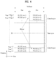
- FIG. 4 illustrates an exemplary uplink subframe structure used in 3GPP LTE/LTE-A.
- a UL subframe can be divided into a control region and a data region in the frequency domain.
- One or more PUCCHs (physical uplink control channels) can be allocated to the control region to carry uplink control information (UCI).
- One or more PUSCHs (Physical uplink shared channels) may be allocated to the data region of the UL subframe to carry user data.
- subcarriers spaced apart from a DC subcarrier are used as the control region.
- subcarriers corresponding to both ends of a UL transmission bandwidth are assigned to UCI transmission.
- the DC subcarrier is a component remaining unused for signal transmission and is mapped to the carrier frequency f0 during frequency up-conversion.
- a PUCCH for a UE is allocated to an RB pair belonging to resources operating at a carrier frequency and RBs belonging to the RB pair occupy different subcarriers in two slots. Assignment of the PUCCH in this manner is represented as frequency hopping of an RB pair allocated to the PUCCH at a slot boundary. When frequency hopping is not applied, the RB pair occupies the same subcarrier.
- the PUCCH can be used to transmit the following control information.
- the quantity of control information (UCI) that a UE can transmit through a subframe depends on the number of SC-FDMA symbols available for control information transmission.
- the SC-FDMA symbols available for control information transmission correspond to SC-FDMA symbols other than SC-FDMA symbols of the subframe, which are used for reference signal transmission.
- SRS sounding reference signal
- the last SC-FDMA symbol of the subframe is excluded from the SC-FDMA symbols available for control information transmission.
- a reference signal is used to detect coherence of the PUCCH.
- the PUCCH supports various formats according to information transmitted thereon.
- Table 4 shows the mapping relationship between PUCCH formats and UCI in LTE/LTE-A.
- PUCCH format Modulation scheme Number of bits per subframe, M bit Usage Etc. 1 N/A N/A SR (Scheduling Request) 1a BPSK 1 ACK/NACK or SR + ACK/NACK One codeword 1b QPSK 2 ACK/NACK or SR + ACK/NACK Two codeword 2 QPSK 20 CQI/PMI/RI Joint ACK/NACK (extended CP) 2a QPSK+BPSK 21 CQI/PMI/RI + ACK/NACK Normal CP only 2b QPSK+QPSK 22 CQI/PMI/RI + ACK/NACK Normal CP only 3 QPSK 48 ACK/NACK or SR + ACK/NACK or CQI/PMI/RI + ACK/NACK
- PUCCH formats 1/1a/1b are used to transmit ACK/NACK information
- PUCCH format 2/2a/2b are used to carry CSI such as CQI/PMI/RI
- PUCCH format 3 is used to transmit ACK/NACK information.
- signal distortion may occur during transmission since the packet is transmitted through a radio channel.
- the distorted signal needs to be corrected using channel information.
- a signal known to both a transmitter and the receiver is transmitted and channel information is detected with a degree of distortion of the signal when the signal is received through a channel. This signal is called a pilot signal or a reference signal.
- the receiver can receive a correct signal only when the receiver is aware of a channel state between each transmit antenna and each receive antenna. Accordingly, a reference signal needs to be provided per transmit antenna, more specifically, per antenna port.
- Reference signals can be classified into an uplink reference signal and a downlink reference signal.
- the uplink reference signal includes:
- the downlink reference signal includes:
- Reference signals can be classified into a reference signal for channel information acquisition and a reference signal for data demodulation.
- the former needs to be transmitted in a wide band as it is used for a UE to acquire channel information on downlink transmission and received by a UE even if the UE does not receive downlink data in a specific subframe.
- This reference signal is used even in a handover situation.
- the latter is transmitted along with a corresponding resource by an eNB when the eNB transmits a downlink signal and is used for a UE to demodulate data through channel measurement.
- This reference signal needs to be transmitted in a region in which data is transmitted.
- a user equipment In the 3GPP LTE(-A) system, a user equipment (UE) is defined to report CSI to a BS.
- the CSI collectively refers to information indicating the quality of a radio channel (also called a link) created between a UE and an antenna port.
- the CSI includes, for example, a rank indicator (RI), a precoding matrix indicator (PMI), and a channel quality indicator (CQI).
- RI which indicates rank information about a channel, refers to the number of streams that a UE receives through the same time-frequency resource. The RI value is determined depending on long-term fading of the channel, and is thus usually fed back to the BS by the UE with a longer period than for the PMI and CQI.
- the PMI which has a value reflecting the channel space property, indicates a precoding index preferred by the UE based on a metric such as SINR.
- the CQI which has a value indicating the intensity of a channel, typically refers to a receive SINR which may be obtained by the BS when the PMI is used.
- the UE calculates, based on measurement of the radio channel, a preferred PMI and RI from which an optimum or highest transmission rate may be derived when used by the BS in the current channel state, and feeds back the calculated PMI and RI to the BS.
- the CQI refers to a modulation and coding scheme providing an acceptable packet error probability for the PMI/RI that is fed back.
- an uplink channel used for CSI transmission is configured as shown in Table 5.
- Table 5 Scheduling scheme Periodic CSI transmission Aperiodic CSI transmission Frequency non-selective PUCCH - Frequency selective PUCCH PUSCH
- CSI may be transmitted with a periodicity defined in a higher layer, using a physical uplink control channel (PUCCH).
- a physical uplink shared channel (PUSCH) may be aperiodically used to transmit the CSI. Transmission of the CSI over the PUSCH is possible only in the case of frequency selective scheduling and aperiodic CSI transmission.
- CSI transmission schemes according to scheduling schemes and periodicity will be described.
- a PUSCH scheduling control signal (UL grant) transmitted over a PDCCH may include a control signal for requesting transmission of CSI.
- the table below shows modes of the UE in which the CQI, PMI and RI are transmitted over the PUSCH..
- the transmission modes in Table 6 are selected in a higher layer, and the CQI/PMI/RI are all transmitted in a PUSCH subframe.
- uplink transmission methods for the UE according to the respective modes will be described.
- Mode 1-2 represents a case where precoding matrices are selected on the assumption that data is transmitted only in subbands.
- the UE generates a CQI on the assumption of a precoding matrix selected for a system band or a whole band (set S) designated in a higher layer.
- the UE may transmit a CQI and a PMI value for each subband.
- the size of each subband may depend on the size of the system band.
- a UE in Mode 2-0 may select M preferred subbands for a system band or a band (set S) designated in a higher layer.
- the UE may generate one CQI value on the assumption that data is transmitted for the M selected subbands.
- the UE additionally reports one CQI (wideband CQI) value for the system band or set S. If there are multiple codewords for the M selected subbands, the UE defines a CQI value for each codeword in a differential form.
- the differential CQI value is determined as a difference between an index corresponding to the CQI value for the M selected subbands and a wideband (WB) CQI index.
- the UE in Mode 2-0 may transmit, to a BS, information about the positions of the M selected subbands, one CQI value for the M selected subbands and a CQI value generated for the whole band or designated band (set S).
- the size of a subband and the value of M may depend on the size of the system band.
- a UE in Mode 2-2 may select positions of M preferred subbands and a single precoding matrix for the M preferred subbands simultaneously on the assumption that data is transmitted through the M preferred subbands.
- a CQI value for the M preferred subbands is defined for each codeword.
- the UE additionally generates a wideband CQI value for the system band or a designated band (set S).
- the UE in Mode 2-2 may transmit, to the BS, information about the positions of the M preferred subbands, one CQI value for the M selected subbands and a single PMI for the M preferred subbands, a wideband PMI, and a wideband CQI value.
- the size of a subband and the value of M may depend on the size of the system band.
- a UE in Mode 3-0 generates a wideband CQI value.
- the UE generates a CQI value for each subband on the assumption that data is transmitted through each subband. In this case, even if RI > 1, the CQI value represents only the CQI value for the first codeword.
- a UE in Mode 3-1 generates a single precoding matrix for the system band or a designated band (set S).
- the UE generates a CQI subband for each codeword on the assumption of the single precoding matrix generated for each subband.
- the UE may generate a wideband CQI on the assumption of the single precoding matrix.
- the CQI value for each subband may be expressed in a differential form.
- the subband CQI value is calculated as a difference between the subband CQI index and the wideband CQI index.
- the size of each subband may depend on the size of the system band.
- a UE in Mode 3-2 generates a precoding matrix for each subband in place of a single precoding matrix for the whole band, in contrast with the UE in Mode 3-1.
- the UE may periodically transmit CSI (e.g., CQI/PMI/PTI (precoding type indicator) and/or RI information) to the BS over a PUCCH. If the UE receives a control signal instructing transmission of user data, the UE may transmit a CQI over the PUCCH. Even if the control signal is transmitted over a PUSCH, the CQI/PMI/PTI/RI may be transmitted in one of the modes defined in the following table. [Table 7] PMI feedback type No PMI Single PMI PUCCH CQI feedback type Wideband (wideband CQI) Mode 1-0 Mode 1-1 UE selective (subband CQI) Mode 2-0 Mode 2-1
- a UE may be set in transmission modes as shown in Table 7.
- a bandwidth part may be a set of subbands consecutively positioned in the frequency domain, and cover the system band or a designated band (set S).
- the size of each subband, the size of a BP and the number of BPs may depend on the size of the system band.
- the UE transmits CQIs for respective BPs in ascending order in the frequency domain so as to cover the system band or designated band (set S).
- the UE may have the following PUCCH transmission types according to a transmission combination of CQI/PMI/PTI/RI.
- the CQI/PMI are transmitted in subframes having different periodicities and offsets. If the RI needs to be transmitted in the same subframe as the WB CQI/PMI, the CQI/PMI are not transmitted.
- a 2-bit CSI request field is used in DCI format 0 or 4, for an aperiodic CSI feedback in the current LTE standards. If a plurality of serving cells are configured for a UE in the CA environment, the UE interprets the CSI request field in 2 bits. If one of TM 1 to TM 9 is configured for every component carrier (CC), an aperiodic CSI feedback is triggered according to values listed in Table 8 below. If TM 10 is configured for at least one of all CCs, an aperiodic CSI feedback is triggered according to values listed in Table 9 below.
- each symbol in a slot is defined according to the slot format, and both the downlink symbol and the uplink symbol can be set in one slot , And this case is referred to as a self-contained subframe (or slot) structure.
- each stage configured with RS and feedback type is defined and a signaling method for configuring it for a UE and signaling it to the UE dynamically is proposed.
- each stage of the multi-stage CSI is defined as a pair of an RS for CSI and a feedback type.
- configuration can be given as follows.
- the above CSI process, stage configuration and informations included therein may be configured for a UE by higher layer signaling such as RRC signaling and the like.
- One feedback type may apply to a plurality of stage configurations.
- RSs e.g., a plurality of CSI-RSs of precoding different from BRS
- feedback on each stage may include feedback of all beam indexes.
- mapping between port/beam index of each RS and feedback index may be defined for each RS.
- a beam index 0 to be fed back may correspond to a lowest port/beam index.
- BRS may correspond to beam indexes 0 to 7 to be fed back by ports 0 to 7, respectively.
- Beam Refinement Reference Signal (BRRS) may correspond to beam indexes 0 to 7 to be fed back by ports 600 to 607, respectively.
- BRRS Beam Refinement Reference Signal
- the partial band restriction in the above partial band selection and CSI tracking may be used for dedicated partial band reporting per service by a BS.
- a BS may configure a specific UE to calculate/report CSI of a partial band (e.g., partial band for eMBB, URLLC, or MTC) for each service in order to acquire CSI for a partial band corresponding to a service to be used by the specific UE.
- the BS may configure the specific UE to transmit RS on a partial band dedicated to a UE only through selection of CSI acquired from the above scheme, MIB/SIB, higher layer signaling or the like and calculate and report CSI on the corresponding partial band only.
- the partial band restriction in the above partial band selection and CSI tracking may mean a scheme that a subband scheduled to a UE by a BS may be used continuously until transmission of data is finished or there is a separate update in aspect of resource allocation using a subband CSI.
- This scheme is also usable for a per-service dedicated partial band reporting.
- a BS determines a data transmission scheme (e.g., CQI, precoding, transmission layer) to use for a UE.
- a data transmission scheme e.g., CQI, precoding, transmission layer
- Multi-stage CSI is configured with a plurality of CSI stages. As each CSI stage, an RS feedback type pair in the following may be considered.
- a CSI stage considered by considering the number of RS and the frequency granularity of RS in RS aspect and the property of frequency granularity of feedback in aspect of feedback type, other property may be additionally considered as follows.
- a UE may calculate CSI on a designated feedback type using a designated RS and report it to a BS using a designated feedback resource (e.g., time-frequency resource.
- a designated feedback resource e.g., time-frequency resource.
- a partial band RS corresponds to a scheme of transmitting RS for the entire designated partial band. This may be the same as a per-service dedicated partial band. Or, when a separate update exists simply after subband scheduling in a BS or it is intended to make data transmission on a corresponding subband until the end of data transmission, it may be the same as the corresponding subband.
- a partial band may correspond to a frequency resource differing in system numerology such as TTI, subframe/slot length, subcarrier spacing, etc. to support a different service from a physical layer viewpoint, it may be defined as follows.
- a scheme of substantially defining a partial band for a UE 1) includes a band configured within a band having the same numerology; and 2) enables UE's control channel monitoring and/or substantial data scheduling to be performed within the corresponding partial band.
- a separate partial band i.e., partial band CSI-RS/IMR
- CSI calculating/reporting should be also independently performed on each partial band similarly.
- a partial band CSI-RS is semi-static in frequency resource fluctuation property, it may be configured in advance through higher layer signaling (e.g., RRC signaling).
- RRC signaling e.g., RRC signaling
- a subband CSI-RS needs to be designated dynamically according to a BS traffic situation, it may be dynamically designated through L1 signaling or L2 signaling such as DCI.
- a resource candidate that can carry a subband CSI-RS such a candidate is configured in advance through higher layer signaling such as RRC signaling and the subband CSI-RS may be then triggered on or off dynamically through L1/L2 signaling.
- partial band configuration information e.g., PRB start index and PRB last index
- subband configuration information e.g., subband size: N PRBs
- a subband bandwidth may be determined as N PRBs according to N (where N is a natural number) determined based on a system bandwidth, a UE-specific wideband bandwidth or a partial band bandwidth.
- information indicating what kind of subband CSI-RS is transmitted within a partial band may be included in aperiodic CSI-RS triggering DCI in form of a bitmap.
- the bitmap information may be included in CSI-RS on/off DCI on semi-persistent CSI-RS transmission.
- a partial band may be equal to a bandwidth part.
- one or more bandwidth part configuration may be configured per Component Carrier (CC) for a UE, and each bandwidth part is configured with a group of contiguous PRBs.
- a bandwidth of the bandwidth part is equal to or smaller than a maximum bandwidth (performance) supported by a UE but is equal to or greater than a Synchronization Signal (SS) bandwidth used for beam management at least.
- Such configuration of the bandwidth part may include numerology, frequency position (e.g., center frequency) or bandwidth.
- Each bandwidth part is associated with specific numerology (e.g., subcarrier spacing, CP type, etc.), and a UE expects that at least one DL bandwidth part and at least one UL bandwidth part in a set of the configured bandwidth parts will be activated at a given timing.
- the UE is assumed as performing transmission/reception within the activated DL/UL bandwidth part(s) using the associated numerology.
- a wideband RS, a partial band RS and a subband RS may be defined separately. Namely, they may be divided into three layers of a wideband RS, a partial band RS and a subband RS.
- the subband RS has the same granularity of the subband CSI. Namely, a plurality of subband RSs may be defined within an RS defined partial band or wideband.
- the wideband may mean a maximum bandwidth configured for the UE to use. If a UE is a UE for a specific service only, a wideband RS and a partial band RS of the UE may have the same frequency granularity. Namely, a wideband in a wideband RS may be defined as follows.
- a BS may set a band, which is equal to or smaller than a maximum frequency band usable by a UE, as a bandwidth candidate for receiving data, define such a band as one wideband, and configure it in unit of one CSI related operation.
- the wideband may be configured for a UE by a method such as System Information Block (SIB) or the like, or configured through higher layer signaling such as RRC signaling or the like for better flexibility.
- SIB System Information Block
- RRC signaling Radio Resource Control
- the wideband RS and the wideband CSI may be performed independently from RS transmission and CSI measurement/reporting operations for another wideband, as RS transmission and CSI measurement/reporting operations for the respective widebands configured for the UE.
- a plurality of partial bands configured with different numerologies may be defined individually within each wideband (available for both TDM and FDM), and a UE-side partial band defined within wideband may correspond to a portion of a partial band (e.g., a band having the same numerology) configured in aspect of a BS only. If single numerology is defined within the corresponding wideband, a wideband CSI and a partial band CSI may coincide with each other. If so, the partial band CSI (or, the reporting of the partial band CSI) may be skipped.
- a BS may configure a wideband RS with the same frequency granularity of a partial band RS. So to speak, a frequency region occupied by each of a wideband and a partial band may have same size.
- a specific operation e.g., mMTC operation, data subband operation
- a wideband may become a unit of a frequency band for transmitting control and/or data for a UE, and more typically, a unit for transmitting one Transport Block (TB).
- a partial band having a different numerology within a single wideband may not be FDMed or be assumed as not FDMed at a specific timing at least.
- a plurality of partial bands defined within a single wideband may be possibly TDMed with each other.
- two partial bands, which have different subcarrier spacing or use a frequency band of the same size may be defined within a wideband but are used at different timings, respectively.
- a separate CSI process may be configured per wideband. Namely, independent CSI-RS or CSI reporting configuration is given in unit of 'wideband', and CSI-RS's transmission and measurement/reporting operation are independently performed. In this case, CSI on a plurality of widebands may be reported on a single UL resource.
- a BS may transmit CSI-RS on a whole band viewable by a UE.
- the BS transmits a plurality of wideband CSI-RSs that cover a whole band of interest, thereby using it for the usage of beam management or RRM measurement.
- the BS may transmit CSI-RS for the super-wideband.
- a reference resource may refer to a bandwidth within a single timing (e.g., slot). If a UE is unable to support a whole bandwidth at a time, a reference resource of the super-wideband may include aggregation across partial bandwidth through several timings (e.g., slot).
- a wideband means a frequency band on which a control channel is transmitted, and may target a frequency band on which a control channel is scheduled instead of a frequency band on which data is scheduled.
- a wideband RS may be transmitted by targeting the control channel scheduled frequency band or a CSI targeting the corresponding band may be defined as a wideband CSI. If a data transmitted band is different from a control channel transmitted band, a UE reports and uses a CSI for a control channel through a wideband CSI, thereby performing a further stable control channel transmission.
- a UE In each CSI calculation, a UE is assumed as having numerology having the same target band (e.g., subcarrier spacing, TTI size).
- numerology e.g., subcarrier spacing, TTI size.
- RS for interference measurement i.e., CSI-Interference Measurement (CSI-IM)
- CSI-IM CSI-Interference Measurement
- wideband CSI-IM/partial band CSI-IM/subband CSI-IM may be defined as granularity for CSI-IM and included in the following stage. Particularly, as one RS and a plurality of CSI-IMs are included in each stage, it is able to report CSI on multi-interference assumption.
- a BS may inform a UE of such a target band of interference measurement on CSI by higher layer signaling such as RRC signaling semi-statically in case of a partial band CSI-IM or by L1 signaling such as DCI dynamically in case of a subband CSI-IM.
- higher layer signaling such as RRC signaling semi-statically in case of a partial band CSI-IM or by L1 signaling such as DCI dynamically in case of a subband CSI-IM.
- CSI-IM may have frequency granularity different from that of RS for CSI.
- wideband/partial band/subband configuration for IM may be set different from wideband/partial band/subband configuration for CSI-RS resource.
- configuration for CSI measurement is set for a UE, combination of CSI-RS and CSI-IM having different frequency granularities is possible.
- subband RS for CSI and partial band CSI-IM are accompanied or RS for CSI on different subband sizes and CSI-IM are defined and accompanied.
- frequency granularity for CSI reporting may be set independently from CSI-RS or CSI-IM.
- combination of different granularities is possible. For example, it is possible to indicate a subband CSI reporting using wideband CSI-RS and partial band CSI-IM.
- wideband CSI means CSI for a corresponding partial band (i.e., a whole region in which a partial band RS is transmitted).
- Non-Zero Power (NZP) CSI-RS may be followed identically.
- NZP Non-Zero Power
- CSI reporting configuration 1 connected to resource configuration 1 (together with bandwidth part 1) and CSI reporting configuration 2 connected to resource configuration 2 (together with bandwidth part 2) are used for a UE, it is able to calculate/report CSI on the bandwidth part 1 and CSI on the bandwidth part 2.
- a BS may dynamically instruct a UE of CSI reporting configuration corresponding to a bandwidth part to be calculated.
- Resource configuration for a plurality of bandwidth parts may be set for one CSI reporting configuration.
- resource configuration 1 (together with bandwidth part 1) and resource configuration 2 (together with bandwidth part 2) may be included in one CSI reporting configuration.
- CSI on a plurality of partial bands for the CSI reporting configuration may be simultaneously calculated/reported.
- a BS dynamically instructs a UE of a specific resource, thereby instructing the UE to calculate/report CSI on a specific bandwidth part.
- subband CSI a plurality of subbands are defined within an RS defined partial band or wideband and CSI on each subband is calculated and reported.
- it may mean a following scheme.
- an eMBB partial band is defined, when a specific UE is set to use a corresponding partial band/service, several subbands are defined within the eMBB partial band. Hence, the UE calculates and reports CSI in unit of the corresponding subband.
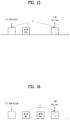
- FIG. 5 shows the relationship among a system bandwidth, partial band and subband.
- a multi-stage CSI of one of 2 CSI stages may be considered.
- 2 stages may be defined as follows.
- two or more purposes may be defined in one CSI stage as follows.
- one stage may be defined across a plurality of subframes.
- a UE uses partial band restriction that transmission keeps being performed on a scheduled subband, the following can be defined.
- 3 CSI stages may be defined.
- 3 stages when it is intended to use a per-service dedicated partial band and select a service/partial band using a partial band CSI through a wideband RS, 3 stages may be defined as follows.
- selection of an analog beam may be included in a mult0stage CSI process.
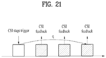
- 'CSI stage trigger' may be defined for an operation of each stage (i.e., RS transmission instruction and aperiodic CSI request) and transmitted to a UE.
- 2-bit CSI stage trigger is transmitted on DCI and the following state may be defined for each state.
- State Process 00 No trigger 01 Stage I. Digital beam selection - Multiple wideband RS with different precoding, CRI 10 Stage II. Partial band selection - Wideband RS, subband selection 11 Stage III. CSI tracking - Partial band RS, wideband CSI
- the following contents may be transmitted from a BS to a UE by being included in DCI.
- Bitmap An RS set corresponding to each bit of a bitmap is designated, and a BS may transmit it by setting a bit, which corresponds to the RS set to transmit, to 1.
- a UE may read the corresponding bitmap and measure an RS corresponding to each bit designated as 1.
- a plurality of RS patterns are set for a UE through higher layer signaling such as RRC signaling and an index is given to each RS pattern. If the RS number is signaled to the UE through DCI, the UE may measure CSI using RS resources amounting to the corresponding RS number by starting with a minimum index number (e.g., 1).
- a plurality of RS patterns are set for a UE through higher layer signaling such as RRC signaling, and a BS uses plural/single RS indicator to indicate whether all of the RSs configured at the corresponding timing or a single RS configured by the BS is used.
- the corresponding RS configuration may be set for the UE through another DCI content, or CSI may be measured using a beam index for data transmission or an RS corresponding to the beam index.
- An RS set corresponding to each bit of a bitmap is designated, and a BS may transmit it by setting a bit, which corresponds to the RS set to transmit, to 1.
- a UE may read the corresponding bitmap and measure an RS corresponding to each bit designated as 1.
- a BS sets a plurality of RS patterns for a UE through higher layer signaling such as RRC signaling and gives an index to each RS pattern.
- the BS signals an RS index to the UE through DCI, and the UE may measure CSI using an RS corresponding to the corresponding index.
- a BS sets a plurality of RS patterns for a UE through higher layer signaling such as RRC signaling. And, the BS uses plural/single RS indicator to indicate whether all of the RSs configured at the corresponding timing or a single RS configured by the BS is used.
- the corresponding RS configuration may be set for the UE through another DCI content, or CSI may be measured using a beam index for data transmission or an RS corresponding to the beam index.
- a BS may give an index for each RB and inform a UE of an RS starting RB index and an RS ending RB or an RB length.
- the BS may directly inform the UE of the RB index.
- the BS may give an index to a start RB - end RB pair set and inform the UE of the corresponding index.
- An RB corresponding to each bit of a bitmap is designated.
- a BS may set a bit corresponding to an RB, on which an RS will be transmitted, to 1 and transmit it.
- a UE may read the corresponding bitmap and measure RS from the RB corresponding to each bit designated as 1. In this case, a narrow band may be designated instead of RB.
- a BS may give an index to a narrowband each and inform a UE of an index for a narrow band on which an RS will be transmitted.
- a transmission timing m of CSI-RS in the CSI stage trigger for a plurality of CSI-RSs may be defined as follows.
- the meaning of the m value may be the same as follows.
- the first A-CSI-RS may be transmitted in the same subframe of DCI including the corresponding indication.
- A-CSI-RSs having different usages/properties e.g., A-CSI-RS for channel measurement, A-CSI-RS for interference measurement
- A-CSI-RS for channel measurement e.g., A-CSI-RS for channel measurement
- A-CSI-RS for interference measurement e.g., A-CSI-RS for interference measurement
- a scheme of designating a transmission timing of A-CSI-RS to a timing of an RS transmitted last among different A-CSI-RSs is advantageous for securing time for calculation of CSI.
- FIG. 10 shows an example that a CSI stage trigger and an A-CSI-RS are transmitted in the same subframe. In this case, 'm ⁇ 0' may be defined. if so, a previously transmitted A-CSI-RS may be notified to a UE through a CSI stage trigger after the corresponding A-CSI-RS transmission.
- a transmission timing interval p of A-CSI-RS may be indicated as follows.
- the meaning of the p value may be described as follows.
- FIG. 11 shows 'p' that indicates an interval between the respective A-CSI-RSs.
- FIG. 12 shows 'p' that indicates an interval between an initial A-CSI-RS and a last A-CSI-RS.
- FIG. 12 shows 'p' that indicates an interval between a CSI stage trigger and a last A-CSI-RS.
- A-CSI-RSs (e.g., A-CSI-RS for channel measurement, A-CSI-RS for interference measurement) having different usages/properties are used for one CSI derivation.
- a transmission timing designation scheme for each A-CSI-RS may use a different scheme among the above-described RS timing indication schemes.
- a UE may be informed that a UL resource for a CSI reporting is designated at which timing.
- the BS may designate a CSI feedback timing k for the UE to report an aperiodic CSI on the corresponding CSI stage trigger by the following method.
- the meaning of the k value may be described as follows.
- a specific A-CSI-RS for aperiodic CSI calculation is transmitted at a plurality of timings, in such a case of receiving a CSI stage trigger at the timing that the transmission of a plurality of the A-CSI-RSs does not start yet, a scheme that a CSI feedback timing indicates a timing from a transmission timing of an initial A-CSI-RS is valid.
- A-CSI-RSs having different usages/properties e.g., A-CSI-RS for channel measurement, A-CSI-RS for interference measurement
- A-CSI-RS for channel measurement e.g., A-CSI-RS for channel measurement
- A-CSI-RS for interference measurement e.g., A-CSI-RS for interference measurement
- a scheme of designating a transmission timing of A-CSI-RS to a timing of an RS transmitted last among different A-CSI-RSs is advantageous for securing time for calculation of CSI.
- a case that a plurality of aperiodic RSs are used for calculation of aperiodic CSI is the appropriate example for the above scheme.
- a scheme that a k value designates a distance from the latest transmitted RS among a plurality of RSs is appropriate. Namely, since it is difficult to be dynamically aligned with different Transmission and Reception Points (TRPs), an NZP-CSI-RS transmission timing for inter-cell interference measurement and a transmission timing of A-CSI-RS for channel measurement may be misaligned with each other. This is noticeable between two TRPs that use different UL/DL configurations in particular.
- TRPs Transmission and Reception Point
- an aperiodic CSI trigger triggering an aperiodic CSI reporting is n and that a transmission timing point of an i th RS among CSI-RSs (NZP-CSI-RS for channel measurement and CSI-IM for interference measurement (e.g., including NZP-CSI-RS and ZP-CSI-RS)) used for calculation of a corresponding CSI with reference to the timing point n is mi
- an aperiodic CSI reporting timing point may become may become a timing point (n + max(mi, 0) + k).
- '0' is an example including a case of 'a k value is a distance from a CSI stage trigger' that will be described later. This may be used for a situation that it is intended to indicate a CSI calculation time with reference to a reception timing point of a corresponding signaling in case that A-CSI-RS (or A-CSI-IM) is transmitted before a CSI stage trigger timing point.
- Each mi described above may be understood differently in case of a different A-CSI-RS transmission scheme (e.g., one-shot A-CSI-RS or a plurality of A-CSI-RSs).
- one-shot A-CSI-RS may mean an interval (or distance) from a corresponding A-CSI-RS and a plurality of A-CSI-RSs may mean an interval (or distance) from a last RS transmission timing point of A-CSI-RS.
- the corresponding mi may mean a timing from a first RS.
- the corresponding mi may mean a timing from a last RS.
- a report timing interval q of an aperiodic CSI in a CSI stage trigger for a plurality of A-CSI-RSs may be indicated as follows.
- the q value may have the following meaning.
- a UE may report CSI on the corresponding RS each.
- 'q p' may be set.
- iii UL resource allocation may be identically applicable to each report timing.
- a UE may calculate CSI by measuring an RS designated to the above DCI and report the corresponding CSI through a UL resource (time, frequency) designated to the above DCI.
- a CSI stage including a transmission of CSI-RS only without CSI reporting there may be a CSI-RS transmission requiring no CSI reporting, e.g., CSI-RS for UE-side beam adjustment.
- a UE may configure a Tx and/or Rx beam of its own using CSI-RS transmitted by a BS without making a mean management related report such as CRI using the corresponding CSI stage.
- it may be able to define a CSI stage for configuring a separate RS transmission to use for calculation of a CSI that will be calculated at a different timing point.
- CSI-RS is transmitted in advance separately from a CSI stage including an NZP CSI-RS based IMR - CSI reporting for inter-TRP interference measurement.
- a UE may be informed of a transmission of an NZP CSI-RS based IMR for inter-TRP interference measurement separately from a CSI stage including an NZP CSI-RS -CSI reporting.
- a UE may be configured to buffer a measurement result of the corresponding RS in order to use the corresponding RS for a job to be used (e.g., CSI calculation).
- a result of the corresponding RS measurement may be automatically buffered until used for a next job.
- the corresponding RS may be used when a next CSI stage report is performed.
- the corresponding RS may be used to report a CSI stage containing a separate configuration indicating 'configuration for RS for another CSI stage'.
- the corresponding CSI stage may be set as 'inter-CSI stage report' to be distinguished from a scheme of UE beam adjustment requiring no CSI reporting, which may be included in the report setting of the corresponding CSI stage.
- an RS transmitted at a previous timing point and unused for a CSI reporting exists at a specific CSI reporting start timing point (e.g., an RS measurement timing point or a CSI calculation start timing point) (moreover, if a subsequent RS valid interval is defined and does not expire), the above operation may be understood as using the corresponding RS in a manner of adding it to the CSI stage.
- the usage of the corresponding RS e.g., CSI-RS or CSI-IM
- a corresponding CSI stage may include RS setting.
- 'inter-CSI stage RS report' may be configured, which may be included in the RS setting of the corresponding CSI stage. In this case, if there is an RS not reported as transmitted previously, a CSI reporting is performed by including the corresponding RS. Otherwise, a CSI reporting may be performed using an RS included in a CSI stage of its own only or the corresponding report may be skipped.
- inter-CSI stage dependency is not limited to a transmission of a previously transmitted RS only, if an additional RS is transmitted from another CSI stage later, a CSI reporting of the corresponding CSI stage may be performed using a measurement of the corresponding RS.
- 'RS valid interval' it is able to inform a UE of a time usable for a CSI reporting (of another CSI stage) by buffering the above RS measurement result, which may be defined in advance or included in the corresponding RS configuration/CSI stage configuration. If the RS valid interval expires, the RS measurement result may be regarded as not existing previously. Moreover, if the corresponding CSI stage includes 'inter-CSI stage RS' configuration, CSI including an RS included in the corresponding CSI stage only may be reported or the corresponding CSI reporting may be skipped. Particularly, according to the RS purpose (e.g., beam management, CSI reporting), the value or a range of a settable value may be defined differently.
- the RS purpose e.g., beam management, CSI reporting
- the aforementioned CSI reporting timing may be defined with reference to a CSI stage corresponding to a last transmitted RS.
- a CSI reporting timing may be defined with reference to a last transmitted RS transmission/reception timing.
- a CSI stage triggered with a DCI transmitted at a timing of transmitting the corresponding RS may be regarded as calculating CSI including a previously transmitted RS.
- DCI for triggering the CSI stage #2 may be transmitted in a corresponding slot as soon as an RS is transmitted in an RS transmission opportunity designated in the CSI stage #1.
- a CSI may be calculated/reported using an RS transmitted at the same time of the timing of transmitting the corresponding DCI.
- the DCI for triggering the CSI stage #1 may include DL-related DCI.
- the 'RS transmission opportunity' designated in the CSI stage #1 may mean a transmission opportunity of a DCI that will indicate (a CSI reporting of) a CSI stage to use the corresponding RS simultaneously.
- a CSI stage mentioned in the present specification may be understood as a scheme similar to 'measurement setting' currently discussed in NR MIMO.
- one RS - report set configured as linking 'resource setting' and 'report setting', which are configured separately, at 'measurement setting' may be understood as referring to the concept similar to a CSI stage in the present specification. Additionally, for better flexibility, it is also possible to perform the link between the resource setting and the report setting through MAC signaling.
- An RS resource indication field is defined within a DCI, and the corresponding field may be interpreted differently according to the above CSI stage indication.
- an RS resource indication field of total 8 bits is defined.
- it may be interpreted as a bitmap designating an RS configuration among a plurality of RS configurations of total 8 RRC configured types.
- it may be interpreted as one of total 64 RRC configured RS patterns (2 bits reserved).
- a 1-bit CSI trigger instead of the CSI stage trigger and setting an expiration timer for each stage (i.e., an RS-feedback type pair)
- the BS may check whether the corresponding CSI stage trigger/CSI trigger is received by checking whether a CSI feedback is received on a which UL resource. In this case, the BS does not transmit a plurality of the CSI stage triggers/CSI triggers for a predetermined time (e.g., 4 ms) (particularly, when the stage using the expiration timer is triggered), and may expect that the UE will not receive two or more CSI stage triggers/CSI triggers for a predetermined time (e.g., 4 ms).
- a predetermined time e.g. 4 ms
- the UE may report feedback on the initial CSI stage trigger/CSI trigger only.
- a CSI-RS mentioned in the present specification is a reference signal used for calculation of a CSI and includes an NZP-CSI-RS for channel measurement and an NZP-CSI-RS for interference measurement and/or a ZP-CSI-RS, i.e., a CSI-IM.
- the CSI-RS is usable for CSI calculation by being substituted with an RS (e.g., BRS, BRRS, RRM-RS, DMRS) of another type according to a configuration.
- each stage may be configured through L3 signaling such as RRC configuration.
- This configuration may include all or some of the above-described contents.
- L2 signaling such as MAC is usable.
- a range selectable by each content may be restricted.
- candidates of selectable RE patterns are configured by RRC, and a pattern to be actually used among the candidates may be configured for each CSI stage through L2 signaling.
- Measurement Restriction may be put on IMR.
- the existing MR considered in LTE is a scheme of setting whether a measurement result may be averaged time-wise, and NR continues a discussion on expanding it frequency-wise. Therefore, in the measurement of interference, it may be expanded to a scheme of setting a size and position of a resource group that may be regarded as having the same measurement value.
- a UE may consider a frequency resource unit that may average an interference measurement value based on the corresponding parameter.
- an interference signal coming into a corresponding IMR may include real data.
- the corresponding interference consists of resource units to which the same precoding is applied.
- a UE may be aware of a unit to which a different precoding is applied, i.e., a size of a Precoding Resource block Group (PRG) through a system bandwidth of the corresponding cell.
- PRG Precoding Resource block Group
- a UE may be informed on a Frequency-Measurement Restriction (F-MR) resource size for IMR.
- the UE may measure more accurate interference by averaging measurement values of interference within a designated F-MR resource. So to speak, the UE does not perform an operation of averaging and the like on the assumption that a measurement value in IMR included in a different F-MR resource is different. This may be more usefully usable to raise the accuracy of interference measurement in case such as an aperiodic IMR having difficulty in time-wise averaging.
- a BS may inform a UE of an exact value of the F-MR resource size.
- a range of a configurable value may vary according to the property of an interference cell, e.g., a resource group size.
- a range of a configurable/signaled value may be determined by a resource group size used by the corresponding interference cell.
- RBG, subband, wideband, system bandwidth size or the like may be considered as such a resource group.
- the resource group size is preferably set to a value of an interference cell.
- a value of a resource group (e.g., wideband/subband/system bandwidth/RBG size) of the interference cell may be indicated.
- F-MR resource size may be configured through RRC signaling or signaled by MAC signaling. Particularly, when the F-MR resource size is indicated through MAC signaling, one of F-MR resource sizes designated in advance through RRC configuration is selected and configured for a UE. In case of configuring it through RRC signaling, a corresponding parameter may be set to a different F-MR resource size through IMR configuration or in unit of measurement setting.
- a UE may be informed of the F-MR resource size through dynamic signaling. This may be included in aperiodic IMR indication, or a set of values that may be designated with DCI may be defined through RRC/MAC signaling for DCI overhead reduction.
- an F-MR resource size may be included.
- an F-MR resource size may be configured in addition to measurement setting (i.e., a set of channel measurement resource(s), interference measurement resource(s) and report setting(s)) for the aperiodic CSI trigger.
- a same F-MR resource is not defined across different partial bands.
- an F-MR resource is configured as a same F-MR resource due to an F-MR resource parameter, if the corresponding F-MR resource is located across a plurality of partial bands, a UE regards two F-MR resource parts as different F-MR resources, respectively.
- a service or/and numerology e.g., symbol duration, subcarrier size
- such a partial band may be set as a different partial band.
- such a partial band of an interference cell may be configured for the UE.
- an F-MR resource may be defined according to the corresponding information.
- F-MR resource signaling may be transmitted to a UE together with F-MR signaling.
- F-MR resource size may be configured for a UE as follows.
- F-MR resource #1/F-MR resource #2 may be configured for a UE through higher layer signaling such as RRC/MAC.
- RRC/MAC higher layer signaling
- an F-MR resource size is defined as one value through the above-described method, it may be signaled to a UE in 1RB unit (MR on)/F-MR resource unit (MR off).
- a BS may configure the corresponding offset for a UE together with the F-MR resource size. Or, since this offset value may not change according to a time for the BS, this may be configured independently from the F-MR resource size. In this case it may be configured through higher layer signaling such as RC and the like.
- precoding is maintained time-wise during a predetermined time interval, e.g., n subframes due to the use of time-wise precoder cycling or the like, the above-described scheme may be similarly usable on a time axis as well.
- BWP BandWidth Part
- a partial band may be equal to or smaller than a bandwidth part.
- the aforementioned partial band information may be substituted with a BandWidth Part (BWP) index.
- BWP BandWidth Part
- a BWP index may be included.
- the resource setting for the NZP CSI-RS/CSI-IM or the like or the report setting for the CSI reporting may additionally include a start/end RB index within the corresponding BWP, or a start RB index and an RB length.
- the main object of the aforementioned partial band CSI-RS/IMR/CSI is to calculate or report an independent CSI according to each service/numerology when different services/numerologies are multiplexed within the same wideband.
- one BWP is determined to be activated and used at a time only, which is applied in a manner of selecting a BWP to use from a plurality of BWPs configured for a UE in advance by dynamic BWP switching.
- a BS and UE automatically select to use a CSI-RS/IMR/CSI reporting configured for the same BWP as the designated activated BWP among the previously configured/selected CSI-RS/IMR/CSI reporting.
- a semi-static resource/report such as a periodic resource/report, it is advantageous in aspect of saving latency for separate RRC configuration.
- the existing enabled semi-persistent resource/report may operate in a manner of being assumed as disabled automatically.
- a CSI-RS/IMR/CSI reporting becoming a designation target of MAC CE or/and DCI signaling may become CSI-RS/IMR/CSI reporting configured for the same BWP of the activated BWP designated at the very timing point.
- an index of a resource intended to be designated by DCI/MAC signaling may be used in a manner of being automatically rearranged/redefined (e.g., in order of the existing indexes) within a resource designated for the corresponding BWP.
- a UE performs a CSI measurement/reporting operation for the CSI-RS/IMR/CSI reporting on the designated BWP.
- a BS In case of intending to calculate a CSI on a BWP other than a BWP designated to a UE, a BS needs to designate a CSI measurement target BWP. Moreover, for CSI measurement on an inactive BWP, a BS designates a separate measurement gap and measures/reports a CSI not on an activated BWP but on another inactive BWP.
- a BS instructs a UE to perform measurement using a previously configured measurement gap. Assuming that there is no transmission of PDSCH/PUSCH in such a measurement gap, the UE attempts CSI measurement on a designated BWP. To this end, the UE attempts the measurement by changing a center frequency of its own and/or Fast Fourier Transform (FFT) size.
- FFT Fast Fourier Transform
- the BS may signal a BWP becoming a target of a CSI measurement/report to the UE.
- Such signaling may explicitly designate a target BWP index. Namely, such designation may be performed in a manner of triggering a CSI-RS/IMR/CSI reporting configured for an inactive BWP, or a CSI target BWP index may be designated in a separate DCI field.
- the UE may perform the corresponding CSI measurement in a measurement gap first appearing after the trigger among the previously configured periodic/semi-persistent measurement gaps. Or, to this end, a dynamic measurement gap is defined.
- Such a dynamic measurement gap trigger may be joint-encoded with the aforementioned CSI target BWP (related) index. So to speak, when the BS gives an instruction of a CSI measurement on an inactive BWP, the UE operates without PDSCH reception/PUSCH transmission by assuming a measurement gap during a time designated to measure the corresponding CSI.
- a periodic/semi-persistent gap may be configured as follows.
- a configured measurement gap appears in a predetermined period/offset. And, a CSI on another BWP is measured in the corresponding measurement gap each time it is necessary.
- a semi-persistent measurement gap may enable/disable the corresponding measurement gap through DCI and/or MAC signaling.
- a UE/BS operation may be agreed without the period/slot offset configuration among the aforementioned configurations or by ignoring the period/slot offset configuration.
- a measurement gap designated with a DCI may start at a timing point of receiving the corresponding DCI by the UE or a timing designated by the corresponding DCI.
- a BS may be able to consider: 1) designating a measurement timing point within a (periodic/semi-persistent) measurement gap; or 2) using a DCI transmitted in a measurement gap used slot. So to speak, when a BS designates a timing point of performing an aperiodic CSI measurement within a measurement gap with a DCI, a UE assumes that a corresponding CSI reporting is measured for an inactive BWP and transmitted as well.
- a measurement (or report) trigger may be designated through a DCI transmitted in a time interval in which a corresponding measurement gap is configured.
- the UE may assume that the corresponding CSI reporting is measured/transmitted for the inactive BWP. Therefore, a signaling target of the CSI-RS/IMR/CSI reporting in such a case may become all irrespective of a BWP.
- a periodic/semi-persistent CSI-RS/IMR may be indicated. In such a case, a CSI is measured/reported on the assumption that the corresponding resource is 'MR on'.
- DCI field states of a CSI-RS/IMR/CSI reporting designating a measurement in a normal situation target a resource for an active BWP only if a measurement within a measurement gap is signaled, the corresponding DCI field states may limit a signaling target of the CSI-RS/IMR/CSI reporting to an inactive BWP (for less DCI signaling overhead) or become the whole irrespective of a BWP (for more flexibility).
- a measurement timing point of a corresponding CSI designated by a BS may be interpreted as a designation of a BWP corresponding to the corresponding slot simultaneously.
- a BWP indication When a BWP indication is designated explicitly, configuration flexibility may be independently given for each CSI-RS/IMR/CSI reporting. Or, since all CSIs should be measured/reported for the same BWP, such a BWP indication may identically apply to the three kinds of CSI-RS/IMR/CSI reporting.
- a CSI is reported on an available UL resource (e.g., PUSCH, long PUCCH) within a first activated BWP after getting out of the measurement gap.
- an available UL resource e.g., PUSCH, long PUCCH
- FIG. 22 is a block diagram of a transmitting device 10 and a receiving device 20 configured to implement exemplary embodiments of the present disclosure.
- the transmitting device 10 and the receiving device 20 respectively include transmitter/receiver 13 and 23 for transmitting and receiving radio signals carrying information, data, signals, and/or messages, memories 12 and 22 for storing information related to communication in a wireless communication system, and processors 11 and 21 connected operationally to the transmitter/receiver 13 and 23 and the memories 12 and 22 and configured to control the memories 12 and 22 and/or the transmitter/receiver 13 and 23 so as to perform at least one of the above-described embodiments of the present disclosure.
- the memories 12 and 22 may store programs for processing and control of the processors 11 and 21 and may temporarily storing input/output information.
- the memories 12 and 22 may be used as buffers.
- the processors 11 and 21 control the overall operation of various modules in the transmitting device 10 or the receiving device 20.
- the processors 11 and 21 may perform various control functions to implement the present disclosure.
- the processors 11 and 21 may be controllers, microcontrollers, microprocessors, or microcomputers.
- the processors 11 and 21 may be implemented by hardware, firmware, software, or a combination thereof.
- ASICs Application Specific Integrated Circuits
- DSPs Digital Signal Processors
- DSPDs Digital Signal Processing Devices
- PLDs Programmable Logic Devices
- FPGAs Field Programmable Gate Arrays
- firmware or software may be configured to include modules, procedures, functions, etc. performing the functions or operations of the present disclosure.
- Firmware or software configured to perform the present disclosure may be included in the processors 11 and 21 or stored in the memories 12 and 22 so as to be driven by the processors 11 and 21.
- the processor 11 of the transmitting device 10 is scheduled from the processor 11 or a scheduler connected to the processor 11 and codes and modulates signals and/or data to be transmitted to the outside.
- the coded and modulated signals and/or data are transmitted to the transmitter/receiver 13.
- the processor 11 converts a data stream to be transmitted into K layers through demultiplexing, channel coding, scrambling and modulation.
- the coded data stream is also referred to as a codeword and is equivalent to a transport block which is a data block provided by a MAC layer.
- One transport block (TB) is coded into one codeword and each codeword is transmitted to the receiving device in the form of one or more layers.
- the transmitter/receiver 13 may include an oscillator.
- the transmitter/receiver 13 may include Nt (where Nt is a positive integer) transmit antennas.
- a signal processing process of the receiving device 20 is the reverse of the signal processing process of the transmitting device 10.
- the transmitter/receiver 23 of the receiving device 10 receives RF signals transmitted by the transmitting device 10.
- the transmitter/receiver 23 may include Nr receive antennas and frequency down-converts each signal received through receive antennas into a baseband signal.
- the transmitter/receiver 23 may include an oscillator for frequency down-conversion.
- the processor 21 decodes and demodulates the radio signals received through the receive antennas and restores data that the transmitting device 10 wishes to transmit.
- the transmitter/receiver 13 and 23 include one or more antennas.
- An antenna performs a function of transmitting signals processed by the transmitter/receiver 13 and 23 to the exterior or receiving radio signals from the exterior to transfer the radio signals to the transmitter/receiver 13 and 23.
- the antenna may also be called an antenna port.
- Each antenna may correspond to one physical antenna or may be configured by a combination of more than one physical antenna element.
- a signal transmitted through each antenna cannot be decomposed by the receiving device 20.
- a reference signal (RS) transmitted through an antenna defines the corresponding antenna viewed from the receiving device 20 and enables the receiving device 20 to perform channel estimation for the antenna, irrespective of whether a channel is a single RF channel from one physical antenna or a composite channel from a plurality of physical antenna elements including the antenna.
- an antenna is defined such that a channel transmitting a symbol on the antenna may be derived from the channel transmitting another symbol on the same antenna.
- a transmitter/receiver supporting a MIMO function of transmitting and receiving data using a plurality of antennas may be connected to two or more antennas.
- a UE serves as the transmission device 10 on uplink and as the receiving device 20 on downlink.
- an eNB serves as the receiving device 20 on uplink and as the transmission device 10 on downlink.
- the transmitting device and/or the receiving device may be configured as a combination of one or more embodiments of the present disclosure.
- a user equipment performing a channel state report in a wireless communication system may include a transmitter, a receiver, and a processor configured to control the transmitter and the receiver.
- the processor may be configured to receive a channel state report configuration including an index of a first BandWidth Part (BWP), receive a trigger of a channel state report not on the first BWP but on a second BWP, measure a channel state on the second BWP in a measurement gap according to the trigger, and transmit the measured channel state on an available uplink resource within a first activated BWP after the measurement gap to a base station.
- BWP BandWidth Part
- a step of receiving information related to the measurement gap from the base station is further included, and the measurement gap may be defined by a frequency resource within a slot, a period/slot offset, or a slot length.
- the measurement gap may include a first measurement gap after reception of the trigger among preset periodic or semi-persistent measurement gaps.
- the semi-persistent measurement gap may be enabled or disabled by signaling.
- the trigger of the channel state report on the second BWP may include signaling that designates a measurement of the channel state within the measurement gap.
- the trigger of the channel state report on the second BWP may include downlink control information received in the measurement gap configured slot.
- the channel state report configuration may include a start RB index and an end RB index of the first BWP.
- the e present disclosure is usable for wireless communication devices such as a user equipment, a relay, a base station, etc.
Applications Claiming Priority (3)
| Application Number | Priority Date | Filing Date | Title |
|---|---|---|---|
| US201762523739P | 2017-06-22 | 2017-06-22 | |
| US201762557094P | 2017-09-11 | 2017-09-11 | |
| PCT/KR2018/007073 WO2018236180A1 (fr) | 2017-06-22 | 2018-06-22 | Procédé et dispositif pour rendre compte d'un état de canal dans un système de communication sans fil |
Publications (2)
| Publication Number | Publication Date |
|---|---|
| EP3644523A1 true EP3644523A1 (fr) | 2020-04-29 |
| EP3644523A4 EP3644523A4 (fr) | 2021-03-31 |
Family
ID=64737349
Family Applications (1)
| Application Number | Title | Priority Date | Filing Date |
|---|---|---|---|
| EP18820435.8A Pending EP3644523A4 (fr) | 2017-06-22 | 2018-06-22 | Procédé et dispositif pour rendre compte d'un état de canal dans un système de communication sans fil |
Country Status (5)
| Country | Link |
|---|---|
| US (2) | US11595167B2 (fr) |
| EP (1) | EP3644523A4 (fr) |
| KR (1) | KR102186249B1 (fr) |
| CN (1) | CN110771063B (fr) |
| WO (1) | WO2018236180A1 (fr) |
Cited By (3)
| Publication number | Priority date | Publication date | Assignee | Title |
|---|---|---|---|---|
| WO2022151149A1 (fr) * | 2021-01-14 | 2022-07-21 | Apple Inc. | Fonctionnement d'intervalle de mesure dynamique |
| EP4094512A4 (fr) * | 2020-01-23 | 2023-10-18 | Qualcomm Incorporated | Intervalle de mesure d'informations d'état de canal (csi) périodique pour équipements utilisateurs à faible complexité limitée en largeur de bande |
| EP4165896A4 (fr) * | 2020-06-15 | 2024-03-20 | Qualcomm Inc | Déclenchement et notification d'informations d'état de canal |
Families Citing this family (15)
| Publication number | Priority date | Publication date | Assignee | Title |
|---|---|---|---|---|
| RU2747131C1 (ru) * | 2017-08-09 | 2021-04-28 | Нтт Докомо, Инк. | Пользовательский терминал, базовая станция и способ радиосвязи |
| CN109392140B (zh) * | 2017-08-11 | 2020-07-28 | 维沃移动通信有限公司 | 一种用于监听pdcch的方法、终端及网络设备 |
| BR112020008925A2 (pt) * | 2017-11-10 | 2020-10-13 | Ntt Docomo, Inc. | terminal de usuário e método de radiocomunicação em um terminal de usuário |
| CN110661676B (zh) * | 2018-06-29 | 2022-06-28 | 大唐移动通信设备有限公司 | 一种带宽部分的测量方法、配置方法、终端及网络设备 |
| WO2020082211A1 (fr) * | 2018-10-22 | 2020-04-30 | Qualcomm Incorporated | Intervalle de mesure sur demande pour des mesures rrm entre fréquences |
| CN111432478B (zh) * | 2019-01-10 | 2023-06-23 | 大唐移动通信设备有限公司 | 一种bwp切换方法、终端及网络侧设备 |
| WO2020252612A1 (fr) * | 2019-06-17 | 2020-12-24 | Qualcomm Incorporated | Canaux de commande de liaison descendante physique de faible complexité et signalisation associée |
| CN112312547A (zh) * | 2019-07-26 | 2021-02-02 | 大唐移动通信设备有限公司 | 资源分配、确定方法及装置 |
| CN111786704B (zh) * | 2020-06-03 | 2022-05-31 | Oppo广东移动通信有限公司 | 一种cri选择方法、装置、用户设备及存储介质 |
| US11870734B2 (en) * | 2020-07-09 | 2024-01-09 | Qualcomm Incorporated | Dormant bandwidth part (BWP) configuration for full-duplex operation |
| WO2022021223A1 (fr) * | 2020-07-30 | 2022-02-03 | Qualcomm Incorporated | Communication en liaison descendante à largeur de bande limitée pour un saut de fréquence de sous-bwp |
| US11589252B2 (en) * | 2020-12-08 | 2023-02-21 | Qualcomm Incorporated | Configuration for a channel measurement resource (CMR) or an interference measurement resource (IMR) time restriction |
| US20220190897A1 (en) * | 2020-12-14 | 2022-06-16 | Samsung Electronics Co., Ltd. | Codebook for distributed mimo transmission |
| EP4344484A1 (fr) * | 2022-01-05 | 2024-04-03 | ZTE Corporation | Systèmes et procédés de traitement d'ue |
| CN114846828A (zh) * | 2022-03-31 | 2022-08-02 | 北京小米移动软件有限公司 | 信道状态信息csi报告的获取方法、装置及存储介质 |
Family Cites Families (18)
| Publication number | Priority date | Publication date | Assignee | Title |
|---|---|---|---|---|
| US8451803B2 (en) | 2007-10-05 | 2013-05-28 | Qualcomm Incorporated | Methods and apparatus for managing measurement behavior of DRX mode UE |
| JP5560340B2 (ja) | 2009-10-01 | 2014-07-23 | インターデイジタル パテント ホールディングス インコーポレイテッド | マルチ受信機無線送受信ユニット(wtru)において周波数間測定および/または無線アクセス技術(rat)間測定を実行する方法および装置 |
| US8599708B2 (en) * | 2010-01-14 | 2013-12-03 | Qualcomm Incorporated | Channel feedback based on reference signal |
| EP2618505B1 (fr) | 2010-09-14 | 2017-11-29 | LG Electronics Inc. | Procédé et dispositif d'allocation de ressources en voie montante |
| US9559820B2 (en) * | 2011-02-18 | 2017-01-31 | Qualcomm Incorporated | Feedback reporting based on channel state information reference signal (CSI-RS) groups |
| KR20140048991A (ko) * | 2011-08-10 | 2014-04-24 | 후지쯔 가부시끼가이샤 | 채널 상태 정보 보고 방법, 사용자 장치 및 기지국 |
| EP2793414B1 (fr) * | 2011-12-16 | 2016-09-14 | LG Electronics Inc. | Procédé de mesure d'informations d'état de canal dans un système d'accès sans fil et appareil correspondant |
| US9591646B2 (en) * | 2012-06-12 | 2017-03-07 | Qualcomm Incorporated | Reference signal power impact determination in new carrier type in LTE |
| KR20150095501A (ko) | 2014-02-13 | 2015-08-21 | 한국전자통신연구원 | 이기종 네트워크에서 주파수간 신호세기 측정 방법 및 장치 |
| WO2015133823A1 (fr) * | 2014-03-04 | 2015-09-11 | Lg Electronics Inc. | Procédé de réception d'informations de commande pour recevoir un signal de référence de découverte et appareil associé |
| CN105991244A (zh) | 2015-01-29 | 2016-10-05 | 北京三星通信技术研究有限公司 | 测量和报告信道状态信息的方法和设备 |
| US20160323901A1 (en) * | 2015-05-01 | 2016-11-03 | Lg Electronics Inc. | Method for channel measurement and report in wireless communication system and apparatus therefor |
| WO2017034147A1 (fr) * | 2015-08-21 | 2017-03-02 | 엘지전자 주식회사 | Procédé de création de rapport d'état de canal dans un système de communications sans fil, et dispositif associé |
| US10716020B2 (en) * | 2016-02-23 | 2020-07-14 | Samsung Electronics Co., Ltd. | Method and apparatus for measurement reference signal |
| EP3739963A1 (fr) * | 2016-11-04 | 2020-11-18 | Telefonaktiebolaget Lm Ericsson (Publ) | Procédés, station de base et équipement utilisateur |
| US11483810B2 (en) * | 2017-04-03 | 2022-10-25 | Huawei Technologies Co., Ltd. | Methods and systems for resource configuration of wireless communication systems |
| US10855432B2 (en) * | 2018-01-11 | 2020-12-01 | Sharp Kabushiki Kaisha | User equipments, base stations and methods |
| US11451359B2 (en) * | 2019-10-15 | 2022-09-20 | Mediatek Inc. | Secondary cell activation in new radio system |
-
2018
- 2018-06-22 EP EP18820435.8A patent/EP3644523A4/fr active Pending
- 2018-06-22 CN CN201880040978.7A patent/CN110771063B/zh active Active
- 2018-06-22 WO PCT/KR2018/007073 patent/WO2018236180A1/fr unknown
- 2018-06-22 US US16/625,375 patent/US11595167B2/en active Active
- 2018-06-22 KR KR1020197035329A patent/KR102186249B1/ko active IP Right Grant
-
2023
- 2023-02-03 US US18/164,250 patent/US20230188282A1/en active Pending
Cited By (3)
| Publication number | Priority date | Publication date | Assignee | Title |
|---|---|---|---|---|
| EP4094512A4 (fr) * | 2020-01-23 | 2023-10-18 | Qualcomm Incorporated | Intervalle de mesure d'informations d'état de canal (csi) périodique pour équipements utilisateurs à faible complexité limitée en largeur de bande |
| EP4165896A4 (fr) * | 2020-06-15 | 2024-03-20 | Qualcomm Inc | Déclenchement et notification d'informations d'état de canal |
| WO2022151149A1 (fr) * | 2021-01-14 | 2022-07-21 | Apple Inc. | Fonctionnement d'intervalle de mesure dynamique |
Also Published As
| Publication number | Publication date |
|---|---|
| US11595167B2 (en) | 2023-02-28 |
| KR20190141002A (ko) | 2019-12-20 |
| EP3644523A4 (fr) | 2021-03-31 |
| WO2018236180A1 (fr) | 2018-12-27 |
| US20230188282A1 (en) | 2023-06-15 |
| CN110771063B (zh) | 2023-09-01 |
| CN110771063A (zh) | 2020-02-07 |
| US20210409174A1 (en) | 2021-12-30 |
| KR102186249B1 (ko) | 2020-12-03 |
Similar Documents
| Publication | Publication Date | Title |
|---|---|---|
| US20230188282A1 (en) | Method and device for reporting channel state in wireless communication system | |
| US11006303B2 (en) | Channel state reporting method in wireless communication system and device therefor | |
| US10601484B2 (en) | Method for reporting channel state in wireless communication system, and device therefor | |
| US11050540B2 (en) | Method for reporting channel state in wireless communication system and device therefor | |
| EP3471311B1 (fr) | Procédé destiné à rapporter un état de canal dans un système de communication sans fil et dispositif associé | |
| US11251921B2 (en) | Method for reporting channel state in wireless communication system, and apparatus therefor | |
| EP3313011B1 (fr) | Transmission efficace des informations aperiodiques de tpye csi | |
| EP3240202B1 (fr) | Procédé pour rapporter un état de canal dans un système de communication sans fil et appareil associé | |
| EP3471451B1 (fr) | Procédé de mesure d'interférences dans un système de communication sans fil et appareil associé | |
| US11005547B2 (en) | Method for channel state reporting in wireless communication system and apparatus for same | |
| US10122430B2 (en) | Method of transmitting channel state information and apparatus therefor | |
| US20160218788A1 (en) | Method and apparatus for transmitting channel state information | |
| US11051198B2 (en) | Method for channel and interference measurement in wireless communication system and apparatus therefor | |
| US10771141B2 (en) | Method for channel state report in wireless communication system, and device therefor | |
| US11211984B2 (en) | Method for reporting channel state in wireless communication system and device therefor | |
| US11082138B2 (en) | Method for channel state measurement in wireless communication system and apparatus therefor |
Legal Events
| Date | Code | Title | Description |
|---|---|---|---|
| STAA | Information on the status of an ep patent application or granted ep patent |
Free format text: STATUS: THE INTERNATIONAL PUBLICATION HAS BEEN MADE |
|
| PUAI | Public reference made under article 153(3) epc to a published international application that has entered the european phase |
Free format text: ORIGINAL CODE: 0009012 |
|
| STAA | Information on the status of an ep patent application or granted ep patent |
Free format text: STATUS: REQUEST FOR EXAMINATION WAS MADE |
|
| 17P | Request for examination filed |
Effective date: 20200121 |
|
| AK | Designated contracting states |
Kind code of ref document: A1 Designated state(s): AL AT BE BG CH CY CZ DE DK EE ES FI FR GB GR HR HU IE IS IT LI LT LU LV MC MK MT NL NO PL PT RO RS SE SI SK SM TR |
|
| AX | Request for extension of the european patent |
Extension state: BA ME |
|
| DAV | Request for validation of the european patent (deleted) | ||
| DAX | Request for extension of the european patent (deleted) | ||
| A4 | Supplementary search report drawn up and despatched |
Effective date: 20210302 |
|
| RIC1 | Information provided on ipc code assigned before grant |
Ipc: H04B 17/24 20150101ALI20210224BHEP Ipc: H04B 7/06 20060101AFI20210224BHEP Ipc: H04L 25/02 20060101ALI20210224BHEP Ipc: H04B 17/309 20150101ALI20210224BHEP |
|
| STAA | Information on the status of an ep patent application or granted ep patent |
Free format text: STATUS: EXAMINATION IS IN PROGRESS |
|
| 17Q | First examination report despatched |
Effective date: 20230306 |