EP3644498A1 - Thyristor startup device - Google Patents
Thyristor startup device Download PDFInfo
- Publication number
- EP3644498A1 EP3644498A1 EP17914666.7A EP17914666A EP3644498A1 EP 3644498 A1 EP3644498 A1 EP 3644498A1 EP 17914666 A EP17914666 A EP 17914666A EP 3644498 A1 EP3644498 A1 EP 3644498A1
- Authority
- EP
- European Patent Office
- Prior art keywords
- synchronous machine
- rotation speed
- inverter
- thyristor
- thyristor starter
- Prior art date
- Legal status (The legal status is an assumption and is not a legal conclusion. Google has not performed a legal analysis and makes no representation as to the accuracy of the status listed.)
- Granted
Links
Images





Classifications
-
- H—ELECTRICITY
- H02—GENERATION; CONVERSION OR DISTRIBUTION OF ELECTRIC POWER
- H02P—CONTROL OR REGULATION OF ELECTRIC MOTORS, ELECTRIC GENERATORS OR DYNAMO-ELECTRIC CONVERTERS; CONTROLLING TRANSFORMERS, REACTORS OR CHOKE COILS
- H02P1/00—Arrangements for starting electric motors or dynamo-electric converters
- H02P1/16—Arrangements for starting electric motors or dynamo-electric converters for starting dynamo-electric motors or dynamo-electric converters
- H02P1/46—Arrangements for starting electric motors or dynamo-electric converters for starting dynamo-electric motors or dynamo-electric converters for starting an individual synchronous motor
- H02P1/52—Arrangements for starting electric motors or dynamo-electric converters for starting dynamo-electric motors or dynamo-electric converters for starting an individual synchronous motor by progressive increase of frequency of supply to motor
-
- H—ELECTRICITY
- H02—GENERATION; CONVERSION OR DISTRIBUTION OF ELECTRIC POWER
- H02P—CONTROL OR REGULATION OF ELECTRIC MOTORS, ELECTRIC GENERATORS OR DYNAMO-ELECTRIC CONVERTERS; CONTROLLING TRANSFORMERS, REACTORS OR CHOKE COILS
- H02P1/00—Arrangements for starting electric motors or dynamo-electric converters
- H02P1/16—Arrangements for starting electric motors or dynamo-electric converters for starting dynamo-electric motors or dynamo-electric converters
-
- H—ELECTRICITY
- H02—GENERATION; CONVERSION OR DISTRIBUTION OF ELECTRIC POWER
- H02M—APPARATUS FOR CONVERSION BETWEEN AC AND AC, BETWEEN AC AND DC, OR BETWEEN DC AND DC, AND FOR USE WITH MAINS OR SIMILAR POWER SUPPLY SYSTEMS; CONVERSION OF DC OR AC INPUT POWER INTO SURGE OUTPUT POWER; CONTROL OR REGULATION THEREOF
- H02M5/00—Conversion of AC power input into AC power output, e.g. for change of voltage, for change of frequency, for change of number of phases
- H02M5/40—Conversion of AC power input into AC power output, e.g. for change of voltage, for change of frequency, for change of number of phases with intermediate conversion into DC
- H02M5/42—Conversion of AC power input into AC power output, e.g. for change of voltage, for change of frequency, for change of number of phases with intermediate conversion into DC by static converters
- H02M5/44—Conversion of AC power input into AC power output, e.g. for change of voltage, for change of frequency, for change of number of phases with intermediate conversion into DC by static converters using discharge tubes or semiconductor devices to convert the intermediate DC into AC
- H02M5/443—Conversion of AC power input into AC power output, e.g. for change of voltage, for change of frequency, for change of number of phases with intermediate conversion into DC by static converters using discharge tubes or semiconductor devices to convert the intermediate DC into AC using devices of a thyratron or thyristor type requiring extinguishing means
- H02M5/45—Conversion of AC power input into AC power output, e.g. for change of voltage, for change of frequency, for change of number of phases with intermediate conversion into DC by static converters using discharge tubes or semiconductor devices to convert the intermediate DC into AC using devices of a thyratron or thyristor type requiring extinguishing means using semiconductor devices only
- H02M5/4505—Conversion of AC power input into AC power output, e.g. for change of voltage, for change of frequency, for change of number of phases with intermediate conversion into DC by static converters using discharge tubes or semiconductor devices to convert the intermediate DC into AC using devices of a thyratron or thyristor type requiring extinguishing means using semiconductor devices only having a rectifier with controlled elements
-
- H—ELECTRICITY
- H02—GENERATION; CONVERSION OR DISTRIBUTION OF ELECTRIC POWER
- H02P—CONTROL OR REGULATION OF ELECTRIC MOTORS, ELECTRIC GENERATORS OR DYNAMO-ELECTRIC CONVERTERS; CONTROLLING TRANSFORMERS, REACTORS OR CHOKE COILS
- H02P1/00—Arrangements for starting electric motors or dynamo-electric converters
- H02P1/16—Arrangements for starting electric motors or dynamo-electric converters for starting dynamo-electric motors or dynamo-electric converters
- H02P1/46—Arrangements for starting electric motors or dynamo-electric converters for starting dynamo-electric motors or dynamo-electric converters for starting an individual synchronous motor
-
- H—ELECTRICITY
- H02—GENERATION; CONVERSION OR DISTRIBUTION OF ELECTRIC POWER
- H02P—CONTROL OR REGULATION OF ELECTRIC MOTORS, ELECTRIC GENERATORS OR DYNAMO-ELECTRIC CONVERTERS; CONTROLLING TRANSFORMERS, REACTORS OR CHOKE COILS
- H02P23/00—Arrangements or methods for the control of AC motors characterised by a control method other than vector control
- H02P23/0004—Control strategies in general, e.g. linear type, e.g. P, PI, PID, using robust control
- H02P23/0027—Control strategies in general, e.g. linear type, e.g. P, PI, PID, using robust control using different modes of control depending on a parameter, e.g. the speed
-
- H—ELECTRICITY
- H02—GENERATION; CONVERSION OR DISTRIBUTION OF ELECTRIC POWER
- H02P—CONTROL OR REGULATION OF ELECTRIC MOTORS, ELECTRIC GENERATORS OR DYNAMO-ELECTRIC CONVERTERS; CONTROLLING TRANSFORMERS, REACTORS OR CHOKE COILS
- H02P23/00—Arrangements or methods for the control of AC motors characterised by a control method other than vector control
- H02P23/14—Estimation or adaptation of motor parameters, e.g. rotor time constant, flux, speed, current or voltage
-
- H—ELECTRICITY
- H02—GENERATION; CONVERSION OR DISTRIBUTION OF ELECTRIC POWER
- H02P—CONTROL OR REGULATION OF ELECTRIC MOTORS, ELECTRIC GENERATORS OR DYNAMO-ELECTRIC CONVERTERS; CONTROLLING TRANSFORMERS, REACTORS OR CHOKE COILS
- H02P25/00—Arrangements or methods for the control of AC motors characterised by the kind of AC motor or by structural details
- H02P25/02—Arrangements or methods for the control of AC motors characterised by the kind of AC motor or by structural details characterised by the kind of motor
- H02P25/022—Synchronous motors
-
- H—ELECTRICITY
- H02—GENERATION; CONVERSION OR DISTRIBUTION OF ELECTRIC POWER
- H02P—CONTROL OR REGULATION OF ELECTRIC MOTORS, ELECTRIC GENERATORS OR DYNAMO-ELECTRIC CONVERTERS; CONTROLLING TRANSFORMERS, REACTORS OR CHOKE COILS
- H02P27/00—Arrangements or methods for the control of AC motors characterised by the kind of supply voltage
- H02P27/04—Arrangements or methods for the control of AC motors characterised by the kind of supply voltage using variable-frequency supply voltage, e.g. inverter or converter supply voltage
- H02P27/06—Arrangements or methods for the control of AC motors characterised by the kind of supply voltage using variable-frequency supply voltage, e.g. inverter or converter supply voltage using DC to AC converters or inverters
-
- H—ELECTRICITY
- H02—GENERATION; CONVERSION OR DISTRIBUTION OF ELECTRIC POWER
- H02P—CONTROL OR REGULATION OF ELECTRIC MOTORS, ELECTRIC GENERATORS OR DYNAMO-ELECTRIC CONVERTERS; CONTROLLING TRANSFORMERS, REACTORS OR CHOKE COILS
- H02P2201/00—Indexing scheme relating to controlling arrangements characterised by the converter used
- H02P2201/13—DC-link of current link type, e.g. typically for thyristor bridges, having an inductor in series with rectifier
Definitions
- the present invention relates to a thyristor starter.
- Thyristor starters have been developed for starting synchronous machines such as generators and motors (for example, see WO2014/033849 (PTL 1)).
- a thyristor starter includes a converter that converts AC power into DC power, a DC reactor that smoothes DC power, and an inverter that converts DC power applied from the converter through the DC reactor into AC power with a variable frequency to supply the AC power to a synchronous machine.
- the AC power supplied to the synchronous machine is controlled whereby the synchronous machine in a stop state can be started and driven at a predetermined rotation speed.
- the inverter has at least six thyristors.
- the inverter can supply three-phase AC power to the synchronous machine to increase the rotation speed of the synchronous machine, by firing six thyristors two by two in order in synchronization with rotation of the synchronous machine.
- the present invention has been made in order to solve the problem above, and an object of the present invention is to provide a thyristor starter capable of suppressing damage by fault current.
- the converter converts AC power into DC power.
- the DC reactor smoothes the DC power.
- the inverter converts the DC power applied from the converter through the DC reactor into AC power with a variable frequency and supplies the AC power to the synchronous machine.
- the controller controls a firing phase of a thyristor in the inverter.
- the thyristor starter accelerates the synchronous machine from a stop state to a predetermined rotation speed by sequentially performing a first mode of performing commutation of the inverter by intermittently setting DC output current of the converter to zero and a second mode of performing commutation of the inverter by induced voltage of the synchronous machine.
- a phase control angle of the inverter is changed such that a value thereof becomes larger as a rotation speed of the synchronous machine becomes higher.
- the present invention can provide a thyristor starter capable of suppressing damage by fault current.
- Fig. 1 is a circuit block diagram showing a configuration of a thyristor starter according to an embodiment of the present invention.
- a thyristor starter 100 according to the embodiment of the present invention starts a synchronous machine 20 by accelerating the stopped synchronous machine 20 to a predetermined rotation speed.
- Synchronous machine 20 includes a stator having armature windings ATU, ATV, and ATW and a rotor having a field winding 22. Synchronous machine 20 is coupled to, for example, a gas turbine of a thermal power plant and is rotatably driven by the gas turbine.
- a predetermined rotation speed may be referred to as "rated rotation speed". For example, when the frequency of an AC power supply 30 is 60 Hz, the rated rotation speed is set to 3600 rpm.
- Thyristor starter 100 is connected to the secondary side of a transformer TR.
- the primary side of transformer TR is connected to AC power supply 30.
- Transformer TR converts three-phase AC voltage supplied from AC power supply 30 into three-phase AC voltage having a predetermined voltage value and applies the three-phase AC voltage to thyristor starter 100.
- Thyristor starter 100 includes a converter 1, a DC reactor 3, an inverter 2, and an exciter 21.
- Converter 1 is a three-phase full-wave rectifier including at least six thyristors and converts three-phase AC power from transformer TR into DC power with a variable voltage.
- DC reactor 3 is connected between positive-side output terminal 1a of converter 1 and positive-side input terminal 2a of inverter 2.
- DC reactor 3 smoothes DC output current Id from converter 1.
- Negative-side output terminal 1b of converter 1 and negative-side input terminal 2b of inverter 2 are connected to each other.
- Another DC reactor 3 may be connected between negative-side output terminal 1b of converter 1 and negative-side input terminal 2b of inverter 2.
- Inverter 2 is a three-phase external-commutated inverter including at least six thyristors U, V, W, X, Y, and Z. Inverter 2 converts the DC power applied from converter 1 through DC reactor 3 into AC power with a variable frequency and supplies the AC power to synchronous machine 20.
- Exciter 21 supplies field current If to field winding 22 of synchronous machine 20.
- the AC power is supplied from inverter 2 to armature windings ATU, ATV, and ATW, with field current If being supplied to field winding 22, rotation of synchronous machine 20 is accelerated.
- Thyristor starter 100 further includes current transformers 4 and 5, a voltage detector 6, a position detector 7, a current detector 9, an inverter controller 10, and a converter controller 13.
- Current transformer 4 detects three-phase AC current flowing from transformer TR to converter 1 and applies a signal indicating the detected value to current detector 9.
- Current detector 9 calculates DC current Id output from converter 1, based on a signal from current transformer 4, and applies a signal indicating the calculated value to converter controller 13.
- current detector 9 has a full-wave rectifying diode rectifier and converts the detected three-phase AC current into DC current Id.
- Current transformer 5 detects current flowing from inverter 2 to armature windings ATU, ATV, and ATW of synchronous machine 20 and applies a signal indicating the detected value to position detector 7.
- Voltage detector 6 detects instantaneous values of three-phase AC voltages Vu, Vv, and Vw supplied to synchronous machine 20 from inverter 2 and applies a signal indicating the detected values to position detector 7. Specifically, voltage detector 6 detects two line voltages of line voltages of three-phase AC voltages in armature windings ATU, ATV, and ATW of synchronous machine 20 (in Fig. 1 , AC voltage Vuv between the U phase and the V phase and AC voltage Vv-w between the V phase and the W phase).
- AC voltages of the U phase, the V phase, and the W phase can be obtained through calculation by detecting at least two line voltages of AC voltage Vu-v between the U phase and the V phase, AC voltage Vv-w between the V phase and the W phase, and AC voltage Vw-u between the W phase and the U phase.
- This conversion from line voltage to phase voltage is performed in voltage detector 6 or position detector 7.
- Position detector 7 detects the position of the rotor of synchronous machine 20 based on signals from current transformer 5 and voltage detector 6 and applies a signal indicating the detected value to inverter controller 10 and converter controller 13.
- Inverter controller 10 controls a firing phase of inverter 2 based on a signal from position detector 7. Specifically, inverter controller 10 includes a control angle calculator 11 and a gate pulse generator 12.
- Control angle calculator 11 calculates a phase control angle (firing angle) ⁇ based on the detected position of the rotor of synchronous machine 20 and applies the calculated phase control angle ⁇ to gate pulse generator 12. Specifically, when control angle calculator 11 calculates a rotation speed of synchronous machine 20 based on a signal from position detector 7, control angle calculator 11 sets phase control angle ⁇ based on the calculated rotation speed. Control angle calculator 11 may calculate the rotation speed of synchronous machine 20 based on a signal from voltage detector 6 instead of position detector 7.
- Gate pulse generator 12 generates a gate pulse (firing command) to be applied to the gates of the thyristors of inverter 2, based on phase control angle ⁇ received from control angle calculator 11.
- Inverter controller 10 corresponds to an embodiment of "controller”.
- Converter controller 13 controls a firing phase of converter 1, based on a signal from position detector 7 and a signal from current detector 9. Specifically, converter controller 13 controls a firing phase of converter 1 such that DC current Id output from converter 1 matches current command value Id*.
- Converter controller 13 includes a speed controller 14, a current controller 15, a control angle calculator 16, and a gate pulse generator 17.
- Speed controller 14 calculates the rotation speed of synchronous machine 20, based on the detected position of the rotor of synchronous machine 20.
- Speed controller 14 generates current command value Id*, which is a target value of DC current Id, based on the calculated rotation speed.
- Current controller 15 calculates a deviation ⁇ Id between current command value Id* and DC current Id and generates a voltage command value VDC1* based on the calculated deviation ⁇ Id.
- current controller 15 includes a proportional element (P), an integral element (I), and an adder.
- the proportional element multiplies deviation ⁇ Id by a predetermined proportional gain for output to the adder, and the integral element integrates deviation ⁇ Id by a predetermined integral gain for output to the adder.
- the adder adds the outputs from the proportional element and the integral element to generate voltage command value VDC1*.
- Voltage command value VDC1* corresponds to a control command that defines DC voltage VDC1 to be output by converter 1.
- Converter 1 performs control such that DC voltage VDC1 is greater than DC voltage VDC2 on the input terminal side of inverter 2 by the amount of voltage drop by DC reactor 3. DC current Id is thus controlled.
- Control angle calculator 16 calculates phase control angle ⁇ based on voltage command value VDC1* applied from current controller 15. Control angle calculator 16 applies the calculated phase control angle ⁇ to gate pulse generator 17.
- Gate pulse generator 17 generates a gate pulse (firing command) to be applied to the gates of the thyristors of converter 1, based on phase control angle ⁇ received from control angle calculator 16. The switching of converter 1 is controlled in accordance with the gate pulse generated by gate pulse generator 17, whereby DC current Id in accordance with current command value Id* is output from converter 1.
- thyristor starter 100 the basic operation of thyristor starter 100 will be described.
- Fig. 2 is a time chart showing the basic operation of thyristor starter 100.
- Fig. 2 shows the rotation speed of synchronous machine 20, an effective value of induced voltage produced in synchronous machine 20, DC current Id output from converter 1, and field current If.
- thyristor starter 100 commutation of the thyristors in inverter 2 is performed using the induced voltage produced in armature windings ATU, ATV, and ATW of synchronous machine 20. Such commutation is called "load commutation”.
- thyristor starter 100 sequentially switches and performs the intermittent commutation mode (first mode) and the load commutation mode (second mode) so that synchronous machine 20 is accelerated from a stop state to the rated rotation speed.
- synchronous machine 20 in a stop state is started, and then thyristor starter 100 performs the intermittent commutation mode.
- DC current Id exhibits a pulse waveform.
- the peak value is set, for example, such that the integrated value of AC power supplied to synchronous machine 20 during the intermittent commutation mode satisfies the amount of electric power for accelerating synchronous machine 20 in a stop state to the switching rotation speed.
- the rotation speed at which the intermittent commutation mode switches to the load commutation mode may be referred to as "switching rotation speed".
- switching rotation speed is about 10% of the rated rotation speed.
- exciter 21 decreases field current If supplied to field winding 22. As a result, the effective value of the induced voltage is kept at constant voltage VE2 even when the rotation speed changes.
- Fig. 3 is a circuit diagram showing the configuration and the operation of inverter 2 shown in Fig. 1 .
- thyristors U, V, and W have anodes connected together to positive-side input terminal 2a and cathodes connected to output terminals 2c, 2d, and 2e, respectively.
- Thyristors X, Y, and Z have anodes connected to output terminals 2c, 2d, and 2e, respectively, and cathodes connected together to negative-side input terminal 2b.
- One of thyristors U, V, and W and one of thyristors X, Y, and Z are conducting in synchronous with three-phase AC voltages Vu, Vv, and Vw, whereby inverter 2 converts DC power supplied from converter 1 through DC reactor 3 into three-phase AC power with a variable frequency and a variable voltage and applies the converted AC power to the stator (armature windings ATU, ATV, and ATW) of synchronous machine 20. This can increase the rotation speed of synchronous machine 20.
- U-phase voltage Vu of synchronous machine 20 appears at input terminal 2a of inverter 2 through inductance Lu and thyristor U
- W-phase voltage Vw appears at input terminal 2b of inverter 2 through inductance Lw and thyristor Z. That is, AC voltage Vw-u between the W phase and the U phase of synchronous machine 20 appears as DC voltage VDC2 between input terminals 2a and 2b.
- Reactors Lu, Lv, and Lw represent inductances of armature windings ATU, ATV, and ATW, respectively, of synchronous machine 20.
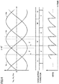
- Fig. 4 is a time chart schematically showing an ideal commutation operation of inverter 2 in the load commutation mode.
- Fig. 4 shows three-phase AC voltages Vu, Vv, and Vw, conducting thyristors of six thyristors U, V, W, X, Y, and Z of inverter 2, and DC voltage VDC2 appearing between input terminals 2a and 2b of inverter 2.
- a gate pulse is applied to the thyristors at a time ahead in phase by a desired angle ⁇ from the reference point. For example, a gate pulse is applied to thyristor V during a period in which thyristor U is conducting, and then a gate pulse is applied to thyristor W during a period in which thyristor V is conducting.
- a gate pulse is applied to thyristor X during a period in which thyristor Z is conducting, and then a gate pulse is applied to thyristor Y during a period in which thyristor X is conducting.
- line voltages Vu-v, Vv-w, and Vw-u of synchronous machine 20 sequentially appear as DC voltage VDC2 between input terminals 2a and 2b of inverter 2.
- Inverter controller 10 fires six thyristors U, V, W, X, Y, and Z two by two in order in response to rotation of synchronous machine 20 to control the path of current flowing through synchronous machine 20.
- Fig. 5 is a diagram showing an example of the relation between the rotation speed of synchronous machine 20 shown in Fig. 1 , and effective value VE of the induced voltage produced in synchronous machine 20 and phase control angle ⁇ .
- phase control angle ⁇ is maintained at substantially zero.
- phase control angle ⁇ is set at ⁇ 1 ( ⁇ 1 > 0).
- phase control angle ⁇ is maintained at constant value ⁇ 1.
- phase control angle ⁇ is changed in accordance with the rotation speed.
- a path of fault current Ia is formed so as to include thyristors V and U as shown in Fig. 6 . Then, sound thyristor V and components such as armature windings may be damaged by fault current Ia.
- the larger fault current Ia is, the greater the damage on the components is, and it is more likely that the components are damaged.
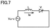
- the path of fault current Ia shown in Fig. 6 can be represented by an equivalent circuit diagram as shown in Fig. 7 .
- the inductance of reactor L corresponds to the total value of inductances of armature windings ATU and ATV.
- AC power supply voltage corresponds to line voltage Vu-v of synchronous machine 20. It is assumed that the resistance component of each of armature windings ATU, ATV, and ATW is negligibly small.
- Fault current Ia is current lagging behind line voltage Vu-v by 90° in phase.
- ⁇ ⁇ /2
- Fig. 8 is an operation waveform of line voltage Vu-v and fault current Ia when ⁇ /2 ⁇ ⁇ ⁇ .
- the circuit equation in the thyristor V conducting period ⁇ ⁇ 0 ⁇ ⁇ + ⁇ is given by Equation (3) below.
- Ia ⁇ 2 V ⁇ L cos ⁇ + cos ⁇
- Ia 2 V ⁇ L 1 ⁇ cos ⁇
- fault current Ia is larger as rotational angular velocity co of synchronous machine 20 is smaller (that is, as the rotation speed of synchronous machine 20 is lower).
- the magnitude of fault current Ia depends on the rotation speed of the synchronous machine at the timing when a short-circuit failure occurs in the thyristors of inverter 2. That is, the lower the rotation speed at that timing is, the larger fault current Ia is.
- the conducting time of fault current Ia is represented by the rotation period of synchronous machine 20 ⁇ 2 ⁇ /2 ⁇ . Therefore, the conducting time is inversely proportional to the rotation speed of synchronous machine 20. This indicates that the lower the rotation speed of synchronous machine 20 is, the longer the conducting time of fault current Ia is.
- fault current Ia flows through components of thyristor starter 100 and synchronous machine 20.
- the magnitude of fault current Ia is larger as the rotation speed of synchronous machine 20 is lower.
- the conducting time of fault current Ia is longer as the rotation speed of synchronous machine 20 is lower.
- the timing when the rotation speed of synchronous machine 20 is lowest in the load commutation mode is the timing immediately after the intermittent commutation mode switches to the load commutation mode.
- phase control angle ⁇ is maintained at constant value ⁇ 1. Therefore, during this time period T1, the conducting time of fault current Ia is inversely proportional to the rotation speed of synchronous machine 20 and is longer as the rotation speed is lower. Thus, if a short-circuit failure occurs during time period T1, the conducting time of fault current Ia is longer, leading to great damage to the components.
- phase control angle ⁇ during time period T1 is changed in accordance with the rotation speed of synchronous machine 20.
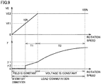
- Fig. 9 is a diagram showing the relation between the rotation speed of synchronous machine 20, and effective value VE of the induced voltage produced in synchronous machine 20 and phase control angle ⁇ , in thyristor starter 100 according to the embodiment, and is compared with Fig. 5 .
- phase control angle ⁇ shown in Fig. 5 is indicated by an alternate long and short dash line.
- Effective value VE of the induced voltage of synchronous machine 20 shown in Fig. 9 is equal to that shown in Fig. 5 .
- phase control angle ⁇ is changed during time period T1 such that a value thereof is larger as the rotation speed of synchronous machine 20 is higher.
- phase control angle ⁇ continuously changes within the range of ⁇ 2 ⁇ ⁇ ⁇ ⁇ 1 in accordance with the rotation speed of synchronous machine 20.
- phase control angle ⁇ may discretely change in accordance with the rotation speed of synchronous machine 20.
- phase control angle ⁇ may change in a stepwise manner within the above-described range.
- the conducting time of fault current Ia can be shorter as the rotation speed of synchronous machine 20 is lower. For example, if a short-circuit failure occurs at the timing immediately after switching to the load commutation mode is performed, the conducting time of fault current Ia is shortened by a factor of ⁇ 2/ ⁇ 1.
- phase control angle ⁇ the magnitude of fault current Ia during time period T1 is also made smaller as compared with Fig. 5 .
- the magnitude of fault current Ia is shortened by a factor of (1 - cos ⁇ 2)/(1 - cos ⁇ 1). According to this, even if the rotation speed of synchronous machine 20 is low at the timing when a short-circuit failure occurs, the damage on the components by fault current Ia can be reduced.
- the data indicating the relation shown in Fig. 9 can be stored in a memory within thyristor starter 100.
- converter controller 13 can generate current command value Id* based on the calculated rotation speed of synchronous machine 20.
- the data may be in table format or in function format.
- the thyristor starter by suppressing the increase in induced voltage produced in synchronous machine 20 in the intermittent commutation mode, the fault current at the timing immediately after the intermittent commutation mode switches to the load commutation mode can be reduced. As a result, the damage on the components of the thyristor starter and the synchronous machine by the fault current can be suppressed.
- synchronous machine 20 is a generator rotatably driven by a gas turbine in a thermal power plant.
- synchronous machine 20 may be a synchronous machine for use in general industrial fields.
- synchronous machine 20 may be a synchronous machine for a cooling blower in a steel plant.
Landscapes
- Engineering & Computer Science (AREA)
- Power Engineering (AREA)
- Control Of Eletrric Generators (AREA)
- Motor And Converter Starters (AREA)
- Inverter Devices (AREA)
Abstract
Description
- The present invention relates to a thyristor starter.
- Thyristor starters have been developed for starting synchronous machines such as generators and motors (for example, see
WO2014/033849 (PTL 1)). A thyristor starter includes a converter that converts AC power into DC power, a DC reactor that smoothes DC power, and an inverter that converts DC power applied from the converter through the DC reactor into AC power with a variable frequency to supply the AC power to a synchronous machine. The AC power supplied to the synchronous machine is controlled whereby the synchronous machine in a stop state can be started and driven at a predetermined rotation speed. - PTL 1:
WO2014/033849 - In the thyristor starter described above, the inverter has at least six thyristors. The inverter can supply three-phase AC power to the synchronous machine to increase the rotation speed of the synchronous machine, by firing six thyristors two by two in order in synchronization with rotation of the synchronous machine.
- However, when a short-circuit failure occurs in any of six thyristors during commutation operation of the inverter, another sound thyristor is fired, whereby a path is formed through which fault current flows through this thyristor. Consequently, components such as sound thyristors and armature windings are damaged by fault current. The larger the fault current is, the greater the damage on the components is, and the possibility that the components are damaged becomes higher.
- The present invention has been made in order to solve the problem above, and an object of the present invention is to provide a thyristor starter capable of suppressing damage by fault current.
- According to an aspect of the present invention, a thyristor starter that starts a synchronous machine includes a converter, a DC reactor, an inverter, and a controller. The converter converts AC power into DC power. The DC reactor smoothes the DC power. The inverter converts the DC power applied from the converter through the DC reactor into AC power with a variable frequency and supplies the AC power to the synchronous machine. The controller controls a firing phase of a thyristor in the inverter. The thyristor starter accelerates the synchronous machine from a stop state to a predetermined rotation speed by sequentially performing a first mode of performing commutation of the inverter by intermittently setting DC output current of the converter to zero and a second mode of performing commutation of the inverter by induced voltage of the synchronous machine. During a first time period from start of performance of the second mode to arrival of the induced voltage at a first voltage value, a phase control angle of the inverter is changed such that a value thereof becomes larger as a rotation speed of the synchronous machine becomes higher.
- The present invention can provide a thyristor starter capable of suppressing damage by fault current.
-
-
Fig. 1 is a circuit block diagram showing a configuration of a thyristor starter according to an embodiment of the present invention. -
Fig. 2 is a time chart showing the basic operation of the thyristor starter. -
Fig. 3 is a circuit diagram showing the configuration and operation of the inverter shown inFig. 1 . -
Fig. 4 is a time chart schematically showing an ideal commutation operation of the inverter in a load commutation mode. -
Fig. 5 is a diagram showing an example of the relation between a rotation speed of the synchronous machine shown inFig. 1 , and an effective value VE of induced voltage produced in the synchronous machine and a phase control angle γ. -
Fig. 6 is a circuit diagram for explaining a path of fault current. -
Fig. 7 is an equivalent circuit diagram schematically illustrating the path of fault current shown inFig. 6 . -
Fig. 8 is a diagram showing operation waveforms of line voltage and fault current. -
Fig. 9 is a diagram showing the relation between the rotation speed of the synchronous machine, and effective value VE of the induced voltage produced in the synchronous machine and phase control angle γ, in the thyristor starter according to the embodiment. - Embodiments of the present invention will be described in detail below with reference to the drawings. The same or corresponding parts are denoted by the same reference signs and a description thereof will not be repeated.
-
Fig. 1 is a circuit block diagram showing a configuration of a thyristor starter according to an embodiment of the present invention. Referring toFig. 1 , athyristor starter 100 according to the embodiment of the present invention starts asynchronous machine 20 by accelerating the stoppedsynchronous machine 20 to a predetermined rotation speed. -
Synchronous machine 20 includes a stator having armature windings ATU, ATV, and ATW and a rotor having a field winding 22.Synchronous machine 20 is coupled to, for example, a gas turbine of a thermal power plant and is rotatably driven by the gas turbine. In the following description, a predetermined rotation speed may be referred to as "rated rotation speed". For example, when the frequency of anAC power supply 30 is 60 Hz, the rated rotation speed is set to 3600 rpm. -
Thyristor starter 100 is connected to the secondary side of a transformer TR. The primary side of transformer TR is connected toAC power supply 30. Transformer TR converts three-phase AC voltage supplied fromAC power supply 30 into three-phase AC voltage having a predetermined voltage value and applies the three-phase AC voltage tothyristor starter 100. -
Thyristor starter 100 includes aconverter 1, a DC reactor 3, aninverter 2, and anexciter 21.Converter 1 is a three-phase full-wave rectifier including at least six thyristors and converts three-phase AC power from transformer TR into DC power with a variable voltage. - DC reactor 3 is connected between positive-
side output terminal 1a ofconverter 1 and positive-side input terminal 2a ofinverter 2. DC reactor 3 smoothes DC output current Id fromconverter 1. Negative-side output terminal 1b ofconverter 1 and negative-side input terminal 2b ofinverter 2 are connected to each other. Another DC reactor 3 may be connected between negative-side output terminal 1b ofconverter 1 and negative-side input terminal 2b ofinverter 2. - Three
output terminals inverter 2 are connected to three armature windings ATU, ATV, and ATW, respectively, ofsynchronous machine 20.Inverter 2 is a three-phase external-commutated inverter including at least six thyristors U, V, W, X, Y, and Z.Inverter 2 converts the DC power applied fromconverter 1 through DC reactor 3 into AC power with a variable frequency and supplies the AC power tosynchronous machine 20. - Exciter 21 supplies field current If to field winding 22 of
synchronous machine 20. When the AC power is supplied frominverter 2 to armature windings ATU, ATV, and ATW, with field current If being supplied to field winding 22, rotation ofsynchronous machine 20 is accelerated. -
Thyristor starter 100 further includescurrent transformers 4 and 5, avoltage detector 6, aposition detector 7, acurrent detector 9, aninverter controller 10, and aconverter controller 13. - Current transformer 4 detects three-phase AC current flowing from transformer TR to converter 1 and applies a signal indicating the detected value to
current detector 9.Current detector 9 calculates DC current Id output fromconverter 1, based on a signal from current transformer 4, and applies a signal indicating the calculated value toconverter controller 13. Specifically,current detector 9 has a full-wave rectifying diode rectifier and converts the detected three-phase AC current into DC current Id. -
Current transformer 5 detects current flowing frominverter 2 to armature windings ATU, ATV, and ATW ofsynchronous machine 20 and applies a signal indicating the detected value toposition detector 7. -
Voltage detector 6 detects instantaneous values of three-phase AC voltages Vu, Vv, and Vw supplied tosynchronous machine 20 frominverter 2 and applies a signal indicating the detected values to positiondetector 7. Specifically,voltage detector 6 detects two line voltages of line voltages of three-phase AC voltages in armature windings ATU, ATV, and ATW of synchronous machine 20 (inFig. 1 , AC voltage Vuv between the U phase and the V phase and AC voltage Vv-w between the V phase and the W phase). In this way, AC voltages of the U phase, the V phase, and the W phase can be obtained through calculation by detecting at least two line voltages of AC voltage Vu-v between the U phase and the V phase, AC voltage Vv-w between the V phase and the W phase, and AC voltage Vw-u between the W phase and the U phase. This conversion from line voltage to phase voltage is performed involtage detector 6 orposition detector 7. -
Position detector 7 detects the position of the rotor ofsynchronous machine 20 based on signals fromcurrent transformer 5 andvoltage detector 6 and applies a signal indicating the detected value toinverter controller 10 andconverter controller 13. -
Inverter controller 10 controls a firing phase ofinverter 2 based on a signal fromposition detector 7. Specifically,inverter controller 10 includes acontrol angle calculator 11 and agate pulse generator 12. -
Control angle calculator 11 calculates a phase control angle (firing angle) γ based on the detected position of the rotor ofsynchronous machine 20 and applies the calculated phase control angle γ togate pulse generator 12. Specifically, whencontrol angle calculator 11 calculates a rotation speed ofsynchronous machine 20 based on a signal fromposition detector 7,control angle calculator 11 sets phase control angle γ based on the calculated rotation speed.Control angle calculator 11 may calculate the rotation speed ofsynchronous machine 20 based on a signal fromvoltage detector 6 instead ofposition detector 7. -
Gate pulse generator 12 generates a gate pulse (firing command) to be applied to the gates of the thyristors ofinverter 2, based on phase control angle γ received fromcontrol angle calculator 11.Inverter controller 10 corresponds to an embodiment of "controller". -
Converter controller 13 controls a firing phase ofconverter 1, based on a signal fromposition detector 7 and a signal fromcurrent detector 9. Specifically,converter controller 13 controls a firing phase ofconverter 1 such that DC current Id output fromconverter 1 matches current command value Id*. -
Converter controller 13 includes aspeed controller 14, acurrent controller 15, acontrol angle calculator 16, and a gate pulse generator 17.Speed controller 14 calculates the rotation speed ofsynchronous machine 20, based on the detected position of the rotor ofsynchronous machine 20.Speed controller 14 generates current command value Id*, which is a target value of DC current Id, based on the calculated rotation speed. -
Current controller 15 calculates a deviation ΔId between current command value Id* and DC current Id and generates a voltage command value VDC1* based on the calculated deviation ΔId. Specifically,current controller 15 includes a proportional element (P), an integral element (I), and an adder. The proportional element multiplies deviation ΔId by a predetermined proportional gain for output to the adder, and the integral element integrates deviation ΔId by a predetermined integral gain for output to the adder. The adder adds the outputs from the proportional element and the integral element to generate voltage command value VDC1*. Voltage command value VDC1* corresponds to a control command that defines DC voltage VDC1 to be output byconverter 1. -
Converter 1 performs control such that DC voltage VDC1 is greater than DC voltage VDC2 on the input terminal side ofinverter 2 by the amount of voltage drop by DC reactor 3. DC current Id is thus controlled. -
Control angle calculator 16 calculates phase control angle α based on voltage command value VDC1* applied fromcurrent controller 15.Control angle calculator 16 applies the calculated phase control angle α to gate pulse generator 17. - Gate pulse generator 17 generates a gate pulse (firing command) to be applied to the gates of the thyristors of
converter 1, based on phase control angle α received fromcontrol angle calculator 16. The switching ofconverter 1 is controlled in accordance with the gate pulse generated by gate pulse generator 17, whereby DC current Id in accordance with current command value Id* is output fromconverter 1. - Referring now to
Fig. 2 , the basic operation ofthyristor starter 100 will be described. -
Fig. 2 is a time chart showing the basic operation ofthyristor starter 100.Fig. 2 shows the rotation speed ofsynchronous machine 20, an effective value of induced voltage produced insynchronous machine 20, DC current Id output fromconverter 1, and field current If. - In
thyristor starter 100, commutation of the thyristors ininverter 2 is performed using the induced voltage produced in armature windings ATU, ATV, and ATW ofsynchronous machine 20. Such commutation is called "load commutation". - However, when the rotation speed of
synchronous machine 20 is low, that is, at startup or at a low speed ofsynchronous machine 20, the induced voltage produced in armature windings ATU, ATV, and ATW is low and therefore commutation of the thyristors may fail. For this reason, when the rotation speed ofsynchronous machine 20 is low, "intermittent commutation" is employed in which commutation ofinverter 2 is performed by intermittently setting DC output current Id ofconverter 1 to zero. - As shown in
Fig. 2 ,thyristor starter 100 sequentially switches and performs the intermittent commutation mode (first mode) and the load commutation mode (second mode) so thatsynchronous machine 20 is accelerated from a stop state to the rated rotation speed. - Specifically, at time t = 0,
synchronous machine 20 in a stop state is started, and thenthyristor starter 100 performs the intermittent commutation mode. In the intermittent commutation mode, DC current Id exhibits a pulse waveform. The peak value of each pulse is usually set to a constant value (Id = 10). The peak value is set, for example, such that the integrated value of AC power supplied tosynchronous machine 20 during the intermittent commutation mode satisfies the amount of electric power for acceleratingsynchronous machine 20 in a stop state to the switching rotation speed. - Then, when the rotation speed of
synchronous machine 20 reaches about 10% of the rated rotation speed,thyristor starter 100 switches from the intermittent commutation mode to the load commutation mode. In the following description, the rotation speed at which the intermittent commutation mode switches to the load commutation mode may be referred to as "switching rotation speed". In the example inFig. 2 , the switching rotation speed is about 10% of the rated rotation speed. - When
synchronous machine 20 in a stop state is started at time t = 0,exciter 21 supplies constant field current If to field winding 22 (If = IfO). Constant field current If causes a constant field magnetic flux to be produced in the rotor.Synchronous machine 20 is accelerated in this state, and thus, the magnitude (effective value) of the induced voltage produced insynchronous machine 20 changes proportionally to the rotation speed ofsynchronous machine 20. - When the effective value of the induced voltage produced in
synchronous machine 20 arrives at a predetermined voltage VE2,exciter 21 decreases field current If supplied to field winding 22. As a result, the effective value of the induced voltage is kept at constant voltage VE2 even when the rotation speed changes. -
Fig. 3 is a circuit diagram showing the configuration and the operation ofinverter 2 shown inFig. 1 . Referring toFig. 3 , thyristors U, V, and W have anodes connected together to positive-side input terminal 2a and cathodes connected tooutput terminals output terminals side input terminal 2b. - One of thyristors U, V, and W and one of thyristors X, Y, and Z are conducting in synchronous with three-phase AC voltages Vu, Vv, and Vw, whereby
inverter 2 converts DC power supplied fromconverter 1 through DC reactor 3 into three-phase AC power with a variable frequency and a variable voltage and applies the converted AC power to the stator (armature windings ATU, ATV, and ATW) ofsynchronous machine 20. This can increase the rotation speed ofsynchronous machine 20. - For example, as shown in
Fig. 3 , when thyristors U and Z are conducting, U-phase voltage Vu ofsynchronous machine 20 appears atinput terminal 2a ofinverter 2 through inductance Lu and thyristor U, and W-phase voltage Vw appears atinput terminal 2b ofinverter 2 through inductance Lw and thyristor Z. That is, AC voltage Vw-u between the W phase and the U phase ofsynchronous machine 20 appears as DC voltage VDC2 betweeninput terminals synchronous machine 20. -
Fig. 4 is a time chart schematically showing an ideal commutation operation ofinverter 2 in the load commutation mode.Fig. 4 shows three-phase AC voltages Vu, Vv, and Vw, conducting thyristors of six thyristors U, V, W, X, Y, and Z ofinverter 2, and DC voltage VDC2 appearing betweeninput terminals inverter 2. - In
Fig. 4 , the point at which line voltages Vu-v, Vv-w, and Vw-u are 0 V is the reference point of phase control angle γ, and at the reference point, γ= 0°. In the load commutation mode, a gate pulse is applied to the thyristors at a time ahead in phase by a desired angle γ from the reference point. For example, a gate pulse is applied to thyristor V during a period in which thyristor U is conducting, and then a gate pulse is applied to thyristor W during a period in which thyristor V is conducting. Similarly, a gate pulse is applied to thyristor X during a period in which thyristor Z is conducting, and then a gate pulse is applied to thyristor Y during a period in which thyristor X is conducting. - In response to transition of the conducting thyristor, line voltages Vu-v, Vv-w, and Vw-u of
synchronous machine 20 sequentially appear as DC voltage VDC2 betweeninput terminals inverter 2.Inverter controller 10 fires six thyristors U, V, W, X, Y, and Z two by two in order in response to rotation ofsynchronous machine 20 to control the path of current flowing throughsynchronous machine 20. -
Fig. 5 is a diagram showing an example of the relation between the rotation speed ofsynchronous machine 20 shown inFig. 1 , and effective value VE of the induced voltage produced insynchronous machine 20 and phase control angle γ. - Referring to
Fig. 5 , during acceleration ofsynchronous machine 20 from the stop state to the switching rotation speed (about 10% of the rated rotation speed), phase control angle γ is maintained at substantially zero. When the rotation speed ofsynchronous machine 20 arrives at the switching rotation speed and the intermittent commutation mode switches to the load commutation mode, phase control angle γ is set at γ1 (γ1 > 0). - As shown in
Fig. 2 , constant field current If is supplied to field winding 22 at this time, and thus, effective value VE of the induced voltage produced insynchronous machine 20 increases proportionally to the rotation speed ofsynchronous machine 20. During a time period from start of performance of the load commutation mode to arrival of effective value VE of the induced voltage at VE2 (corresponding to a time period T1 in the figure), phase control angle γ is maintained at constant value γ1. - As shown in
Fig. 2 , when effective value VE of the induced voltage arrives at VE2, field current If supplied to field winding 22 is decreased. Furthermore, during a time period from arrival of effective value VE of the induced voltage at VE2 to arrival of the rotation speed ofsynchronous machine 20 at the rated rotation speed (corresponding to a time period T2 in the figure), phase control angle γ is changed in accordance with the rotation speed. As a result, during time period T2, effective value VE of the induced voltage is kept at constant voltage VE2 even when the rotation speed changes. - Here, we discuss a case where a short-circuit failure occurs, in which the anode and the cathode are electrically short-circuited in any one of six thyristors U, V, W, X, Y, and Z of
inverter 2 in the load commutation mode. - For example, in a case where a short-circuit failure occurs in thyristor U, when a gate pulse is applied to thyristor V to make thyristor V conducting, a path of fault current Ia is formed so as to include thyristors V and U as shown in
Fig. 6 . Then, sound thyristor V and components such as armature windings may be damaged by fault current Ia. The larger fault current Ia is, the greater the damage on the components is, and it is more likely that the components are damaged. - The path of fault current Ia shown in
Fig. 6 can be represented by an equivalent circuit diagram as shown inFig. 7 . In the equivalent circuit diagram inFig. 7 , the inductance of reactor L corresponds to the total value of inductances of armature windings ATU and ATV. AC power supply voltage corresponds to line voltage Vu-v ofsynchronous machine 20. It is assumed that the resistance component of each of armature windings ATU, ATV, and ATW is negligibly small. - When thyristor V is conducting, fault current Ia flows in thyristor V through reactor L. When the effective value of line voltage Vu-V is V, line voltage Vu-v is written as Equation (1) below.

- Fault current Ia is current lagging behind line voltage Vu-v by 90° in phase. In the case of γ = π/2, fault current Ia is given by Equation (2) below, where L is the inductance of reactor L, and ω is the rotational angular velocity of
synchronous machine 20.
-
Fig. 8 is an operation waveform of line voltage Vu-v and fault current Ia when π/2 ≤ γ< π. The current waveform shown by a broken line inFig. 8 indicates fault current Ia when γ = π/2. - Fault current Ia is a symmetrical waveform with respect to θ = π. The circuit equation in the thyristor V conducting period γ ≤ 0 ≤ π + γ is given by Equation (3) below.

- Solving Equation (3) with θ = ωt = π - γ and given a condition Ia = 0 results in Equation (4) below. This current waveform is the same as the one obtained by removing the portion of π - γ≤ 0 ≤ π + γ from the current waveform of γ = π/2 (broken line).

- Ia is largest when θ = π, and the maximum value is obtained by Equation (5) below.

- According to Equation (5), when line voltage Vu-v of
synchronous machine 20 and the phase control angle γ are constant, fault current Ia is larger as rotational angular velocity co ofsynchronous machine 20 is smaller (that is, as the rotation speed ofsynchronous machine 20 is lower). According to this, the magnitude of fault current Ia depends on the rotation speed of the synchronous machine at the timing when a short-circuit failure occurs in the thyristors ofinverter 2. That is, the lower the rotation speed at that timing is, the larger fault current Ia is. - The conducting time of fault current Ia is represented by the rotation period of
synchronous machine 20 × 2γ/2π. Therefore, the conducting time is inversely proportional to the rotation speed ofsynchronous machine 20. This indicates that the lower the rotation speed ofsynchronous machine 20 is, the longer the conducting time of fault current Ia is. - In this way, if a short-circuit failure occurs in any one of six thyristors U, V, W, X, Y, and Z of
inverter 2 during the load commutation mode, fault current Ia flows through components ofthyristor starter 100 andsynchronous machine 20. The magnitude of fault current Ia is larger as the rotation speed ofsynchronous machine 20 is lower. In addition, the conducting time of fault current Ia is longer as the rotation speed ofsynchronous machine 20 is lower. - According to the time chart in
Fig. 2 , the timing when the rotation speed ofsynchronous machine 20 is lowest in the load commutation mode is the timing immediately after the intermittent commutation mode switches to the load commutation mode. As shown inFig. 5 , during time period T1 from start of performance of the load commutation mode to arrival of effective value VE of the induced voltage produced insynchronous machine 20 at VE2, phase control angle γ is maintained at constant value γ1. Therefore, during this time period T1, the conducting time of fault current Ia is inversely proportional to the rotation speed ofsynchronous machine 20 and is longer as the rotation speed is lower. Thus, if a short-circuit failure occurs during time period T1, the conducting time of fault current Ia is longer, leading to great damage to the components. - Then, in
thyristor starter 100 according to the embodiment, phase control angle γ during time period T1 is changed in accordance with the rotation speed ofsynchronous machine 20. - Control of a firing phase of
inverter 2 performed bythyristor starter 100 according to the embodiment will be described below with reference toFig. 9 . -
Fig. 9 is a diagram showing the relation between the rotation speed ofsynchronous machine 20, and effective value VE of the induced voltage produced insynchronous machine 20 and phase control angle γ, inthyristor starter 100 according to the embodiment, and is compared withFig. 5 . InFig. 9 , phase control angle γ shown inFig. 5 is indicated by an alternate long and short dash line. Effective value VE of the induced voltage ofsynchronous machine 20 shown inFig. 9 is equal to that shown inFig. 5 . - As shown in
Fig. 9 , when the intermittent commutation mode switches to the load commutation mode, phase control angle γ is changed during time period T1 such that a value thereof is larger as the rotation speed ofsynchronous machine 20 is higher. In the example inFig. 9 , phase control angle γ continuously changes within the range of γ2 ≤ γ ≤ γ1 in accordance with the rotation speed ofsynchronous machine 20. However, phase control angle γ may discretely change in accordance with the rotation speed ofsynchronous machine 20. For example, phase control angle γ may change in a stepwise manner within the above-described range. - According to
Fig. 9 , the lower the rotation speed ofsynchronous machine 20 is, the smaller phase control angle γ is. Therefore, the conducting time of fault current Ia can be shorter as the rotation speed ofsynchronous machine 20 is lower. For example, if a short-circuit failure occurs at the timing immediately after switching to the load commutation mode is performed, the conducting time of fault current Ia is shortened by a factor of γ2/γ1. - Furthermore, by making phase control angle γ smaller, the magnitude of fault current Ia during time period T1 is also made smaller as compared with
Fig. 5 . For example, at the timing immediately after switching to the load commutation mode is performed, the magnitude of fault current Ia is shortened by a factor of (1 - cosγ2)/(1 - cosγ1). According to this, even if the rotation speed ofsynchronous machine 20 is low at the timing when a short-circuit failure occurs, the damage on the components by fault current Ia can be reduced. - The data indicating the relation shown in
Fig. 9 can be stored in a memory withinthyristor starter 100. By referring to the data,converter controller 13 can generate current command value Id* based on the calculated rotation speed ofsynchronous machine 20. The data may be in table format or in function format. - As described above, in the thyristor starter according to the embodiment of the present invention, by suppressing the increase in induced voltage produced in
synchronous machine 20 in the intermittent commutation mode, the fault current at the timing immediately after the intermittent commutation mode switches to the load commutation mode can be reduced. As a result, the damage on the components of the thyristor starter and the synchronous machine by the fault current can be suppressed. - In the foregoing embodiment,
synchronous machine 20 is a generator rotatably driven by a gas turbine in a thermal power plant. However, the embodiment is not limited thereto andsynchronous machine 20 may be a synchronous machine for use in general industrial fields. For example,synchronous machine 20 may be a synchronous machine for a cooling blower in a steel plant. - The embodiment disclosed herein is illustrative and not limited to the description above. The scope of the present invention is defined by the claims, and it is intended that all modifications that come within meaning and range of equivalency of the claims are embraced.
- 1 converter; 2 inverter; 3 DC reactor; 4, 5 current transformer; 6 voltage detector; 7 position detector; 9 current detector; 10 inverter controller; 11, 16 control angle calculator; 12, 17 gate pulse generator; 14 speed controller; 15 current controller; 20 synchronous machine; 21 exciter; 22 field winding; 24 rotor; 26 stator; 30 AC power supply; 100 thyristor starter; ATU, ATV, ATW armature winding; U, V, W, X, Y, Z thyristor; TR transformer.
Claims (6)
- A thyristor starter that starts a synchronous machine, the thyristor starter comprising:a converter that converts AC power into DC power;a DC reactor that smoothes the DC power;an inverter that converts the DC power applied from the converter through the DC reactor into AC power with a variable frequency and supplies the AC power to the synchronous machine, anda controller that controls a firing phase of a thyristor in the inverter, whereinthe thyristor starter accelerates the synchronous machine from a stop state to a predetermined rotation speed by sequentially performing a first mode and a second mode, the thyristor starter performing, in the first mode, commutation of the inverter by intermittently setting DC output current of the converter to zero, the thyristor starter performing, in the second mode, commutation of the inverter by induced voltage of the synchronous machine, andduring a first time period from start of performance of the second mode to arrival of the induced voltage at a first voltage value, a phase control angle of the inverter is changed such that a value thereof becomes larger as a rotation speed of the synchronous machine becomes higher.
- The thyristor starter according to claim 1, wherein
the synchronous machine includes a rotor having a field winding, and a stator, the thyristor starter further comprising
an exciter that supplies a field current to the field winding, wherein
in the first and second modes, the thyristor starter increases the induced voltage proportionally to the rotation speed of the synchronous machine by maintaining the field current constant, and
after the induced voltage arrives at the first voltage value in the second mode, the thyristor starter keeps the induced voltage at the first voltage value by decreasing the field current in accordance with the rotation speed of the synchronous machine. - The thyristor starter according to claim 1 or 2, wherein
during the first time period, the phase control angle continuously changes in accordance with the rotation speed of the synchronous machine. - The thyristor starter according to claim 1 or 2, wherein
during the first time period, the phase control angle discretely changes in accordance with the rotation speed of the synchronous machine. - The thyristor starter according to any one of claims 1 to 4, wherein
during a second time period from arrival of the induced voltage at the first voltage value to arrival of the synchronous machine at the predetermined rotation speed, the phase control angle is changed in accordance with the rotation speed of the synchronous machine so as to keep the induced voltage at the first voltage value. - The thyristor starter according to any one of claims 1 to 5, further comprising
a position detector that detects a rotor position of the synchronous machine, wherein
the controller calculates the rotation speed of the synchronous machine based on a detection signal of the position detector, and sets the phase control angle based on the calculated rotation speed of the synchronous machine.
Applications Claiming Priority (1)
| Application Number | Priority Date | Filing Date | Title |
|---|---|---|---|
| PCT/JP2017/022845 WO2018235190A1 (en) | 2017-06-21 | 2017-06-21 | Thyristor start device |
Publications (3)
| Publication Number | Publication Date |
|---|---|
| EP3644498A1 true EP3644498A1 (en) | 2020-04-29 |
| EP3644498A4 EP3644498A4 (en) | 2020-12-30 |
| EP3644498B1 EP3644498B1 (en) | 2025-05-21 |
Family
ID=64736945
Family Applications (1)
| Application Number | Title | Priority Date | Filing Date |
|---|---|---|---|
| EP17914666.7A Active EP3644498B1 (en) | 2017-06-21 | 2017-06-21 | Thyristor starter |
Country Status (4)
| Country | Link |
|---|---|
| US (1) | US11211882B2 (en) |
| EP (1) | EP3644498B1 (en) |
| JP (1) | JP6781343B2 (en) |
| WO (1) | WO2018235190A1 (en) |
Families Citing this family (1)
| Publication number | Priority date | Publication date | Assignee | Title |
|---|---|---|---|---|
| KR102391590B1 (en) * | 2018-04-06 | 2022-04-27 | 도시바 미쓰비시덴키 산교시스템 가부시키가이샤 | power converter |
Family Cites Families (16)
| Publication number | Priority date | Publication date | Assignee | Title |
|---|---|---|---|---|
| JPS5842718B2 (en) * | 1976-04-02 | 1983-09-21 | 株式会社日立製作所 | Control device for commutatorless motor |
| JPS5413919A (en) * | 1977-07-04 | 1979-02-01 | Hitachi Ltd | Preventive controller for torque pulsation |
| JPS56101390A (en) * | 1980-01-11 | 1981-08-13 | Hitachi Ltd | Constant output control system for thyristor motor |
| US4460861A (en) * | 1983-01-21 | 1984-07-17 | Westinghouse Electric Corp. | Control system for machine commutated inverter-synchronous motor drives |
| JPH0724475B2 (en) | 1984-08-31 | 1995-03-15 | 株式会社東芝 | Synchronous motor control method |
| JPH0612954B2 (en) | 1984-11-27 | 1994-02-16 | 株式会社東芝 | Synchronous motor control method |
| JPH05276763A (en) * | 1992-03-24 | 1993-10-22 | Toshiba Corp | Load communication-type inverter |
| JP2003061380A (en) * | 2001-08-10 | 2003-02-28 | Toshiba Corp | Thyristor starter for synchronous machine |
| US7629455B2 (en) * | 2005-12-07 | 2009-12-08 | Monsanto Technology Llc | Zea mays NFB2 promoter |
| US7368890B2 (en) * | 2006-02-07 | 2008-05-06 | Rockwell Automation Technologies, Inc. | Power converter with active discharging for improved auto-restart capability |
| WO2010038282A1 (en) * | 2008-10-01 | 2010-04-08 | 東芝三菱電機産業システム株式会社 | Synchronous machine starting device |
| JP5421287B2 (en) * | 2008-11-18 | 2014-02-19 | 東芝三菱電機産業システム株式会社 | Synchronous machine starting device |
| JP5514826B2 (en) * | 2009-08-24 | 2014-06-04 | 東芝三菱電機産業システム株式会社 | Synchronous machine starting device |
| US8570775B2 (en) * | 2011-02-17 | 2013-10-29 | Rockwell Automation Technologies, Inc. | CMV reduction under bus transient condition |
| US20150236622A1 (en) * | 2012-08-29 | 2015-08-20 | Toshiba Mitsubishi-Electric Industrial Systems Corporation | Thyristor starter |
| US9912259B2 (en) * | 2013-02-14 | 2018-03-06 | Toshiba Mitsubishi-Electric Industrial Systems Corporation | Thyristor starting device and control method therefor |
-
2017
- 2017-06-21 JP JP2019524772A patent/JP6781343B2/en active Active
- 2017-06-21 EP EP17914666.7A patent/EP3644498B1/en active Active
- 2017-06-21 US US16/623,905 patent/US11211882B2/en active Active
- 2017-06-21 WO PCT/JP2017/022845 patent/WO2018235190A1/en not_active Ceased
Also Published As
| Publication number | Publication date |
|---|---|
| WO2018235190A1 (en) | 2018-12-27 |
| EP3644498B1 (en) | 2025-05-21 |
| US20210152104A1 (en) | 2021-05-20 |
| JPWO2018235190A1 (en) | 2020-05-28 |
| EP3644498A4 (en) | 2020-12-30 |
| US11211882B2 (en) | 2021-12-28 |
| JP6781343B2 (en) | 2020-11-04 |
Similar Documents
| Publication | Publication Date | Title |
|---|---|---|
| EP3644494B1 (en) | Thyristor starting device | |
| EP2892149A1 (en) | Thyristor activation device | |
| JPWO2010064318A1 (en) | Synchronous machine starting device | |
| US10951144B2 (en) | Thyristor starter | |
| JP6933728B2 (en) | Thyristor starter | |
| EP3644498B1 (en) | Thyristor starter | |
| Alnajjar et al. | Predictive control of variable frequency brushless excited synchronous generator for more electric aircraft power system | |
| EP3644493B1 (en) | Thyristor starting device | |
| JP7315799B1 (en) | thyristor starter |
Legal Events
| Date | Code | Title | Description |
|---|---|---|---|
| STAA | Information on the status of an ep patent application or granted ep patent |
Free format text: STATUS: THE INTERNATIONAL PUBLICATION HAS BEEN MADE |
|
| PUAI | Public reference made under article 153(3) epc to a published international application that has entered the european phase |
Free format text: ORIGINAL CODE: 0009012 |
|
| STAA | Information on the status of an ep patent application or granted ep patent |
Free format text: STATUS: REQUEST FOR EXAMINATION WAS MADE |
|
| 17P | Request for examination filed |
Effective date: 20200114 |
|
| AK | Designated contracting states |
Kind code of ref document: A1 Designated state(s): AL AT BE BG CH CY CZ DE DK EE ES FI FR GB GR HR HU IE IS IT LI LT LU LV MC MK MT NL NO PL PT RO RS SE SI SK SM TR |
|
| AX | Request for extension of the european patent |
Extension state: BA ME |
|
| DAV | Request for validation of the european patent (deleted) | ||
| DAX | Request for extension of the european patent (deleted) | ||
| REG | Reference to a national code |
Ref country code: DE Ref legal event code: R079 Free format text: PREVIOUS MAIN CLASS: H02P0027060000 Ipc: H02P0001520000 |
|
| A4 | Supplementary search report drawn up and despatched |
Effective date: 20201201 |
|
| RIC1 | Information provided on ipc code assigned before grant |
Ipc: H02P 23/00 20160101ALI20201125BHEP Ipc: H02P 7/293 20160101ALI20201125BHEP Ipc: H02P 27/06 20060101ALI20201125BHEP Ipc: H02P 1/46 20060101ALI20201125BHEP Ipc: H02P 1/52 20060101AFI20201125BHEP |
|
| STAA | Information on the status of an ep patent application or granted ep patent |
Free format text: STATUS: EXAMINATION IS IN PROGRESS |
|
| 17Q | First examination report despatched |
Effective date: 20220513 |
|
| GRAP | Despatch of communication of intention to grant a patent |
Free format text: ORIGINAL CODE: EPIDOSNIGR1 |
|
| STAA | Information on the status of an ep patent application or granted ep patent |
Free format text: STATUS: GRANT OF PATENT IS INTENDED |
|
| INTG | Intention to grant announced |
Effective date: 20241213 |
|
| GRAS | Grant fee paid |
Free format text: ORIGINAL CODE: EPIDOSNIGR3 |
|
| GRAA | (expected) grant |
Free format text: ORIGINAL CODE: 0009210 |
|
| STAA | Information on the status of an ep patent application or granted ep patent |
Free format text: STATUS: THE PATENT HAS BEEN GRANTED |
|
| RAP3 | Party data changed (applicant data changed or rights of an application transferred) |
Owner name: TMEIC CORPORATION |
|
| AK | Designated contracting states |
Kind code of ref document: B1 Designated state(s): AL AT BE BG CH CY CZ DE DK EE ES FI FR GB GR HR HU IE IS IT LI LT LU LV MC MK MT NL NO PL PT RO RS SE SI SK SM TR |
|
| REG | Reference to a national code |
Ref country code: GB Ref legal event code: FG4D |
|
| REG | Reference to a national code |
Ref country code: CH Ref legal event code: EP |
|
| REG | Reference to a national code |
Ref country code: DE Ref legal event code: R096 Ref document number: 602017089615 Country of ref document: DE |
|
| REG | Reference to a national code |
Ref country code: IE Ref legal event code: FG4D |
|
| PGFP | Annual fee paid to national office [announced via postgrant information from national office to epo] |
Ref country code: DE Payment date: 20250527 Year of fee payment: 9 |
|
| PGFP | Annual fee paid to national office [announced via postgrant information from national office to epo] |
Ref country code: GB Payment date: 20250620 Year of fee payment: 9 |
|
| PGFP | Annual fee paid to national office [announced via postgrant information from national office to epo] |
Ref country code: FR Payment date: 20250627 Year of fee payment: 9 |
|
| REG | Reference to a national code |
Ref country code: NL Ref legal event code: MP Effective date: 20250521 |
|
| PG25 | Lapsed in a contracting state [announced via postgrant information from national office to epo] |
Ref country code: PT Free format text: LAPSE BECAUSE OF FAILURE TO SUBMIT A TRANSLATION OF THE DESCRIPTION OR TO PAY THE FEE WITHIN THE PRESCRIBED TIME-LIMIT Effective date: 20250922 Ref country code: ES Free format text: LAPSE BECAUSE OF FAILURE TO SUBMIT A TRANSLATION OF THE DESCRIPTION OR TO PAY THE FEE WITHIN THE PRESCRIBED TIME-LIMIT Effective date: 20250521 Ref country code: FI Free format text: LAPSE BECAUSE OF FAILURE TO SUBMIT A TRANSLATION OF THE DESCRIPTION OR TO PAY THE FEE WITHIN THE PRESCRIBED TIME-LIMIT Effective date: 20250521 |
|
| REG | Reference to a national code |
Ref country code: LT Ref legal event code: MG9D |
|
| PG25 | Lapsed in a contracting state [announced via postgrant information from national office to epo] |
Ref country code: NO Free format text: LAPSE BECAUSE OF FAILURE TO SUBMIT A TRANSLATION OF THE DESCRIPTION OR TO PAY THE FEE WITHIN THE PRESCRIBED TIME-LIMIT Effective date: 20250821 Ref country code: GR Free format text: LAPSE BECAUSE OF FAILURE TO SUBMIT A TRANSLATION OF THE DESCRIPTION OR TO PAY THE FEE WITHIN THE PRESCRIBED TIME-LIMIT Effective date: 20250822 |
|
| PG25 | Lapsed in a contracting state [announced via postgrant information from national office to epo] |
Ref country code: NL Free format text: LAPSE BECAUSE OF FAILURE TO SUBMIT A TRANSLATION OF THE DESCRIPTION OR TO PAY THE FEE WITHIN THE PRESCRIBED TIME-LIMIT Effective date: 20250521 Ref country code: PL Free format text: LAPSE BECAUSE OF FAILURE TO SUBMIT A TRANSLATION OF THE DESCRIPTION OR TO PAY THE FEE WITHIN THE PRESCRIBED TIME-LIMIT Effective date: 20250521 |
|
| PG25 | Lapsed in a contracting state [announced via postgrant information from national office to epo] |
Ref country code: BG Free format text: LAPSE BECAUSE OF FAILURE TO SUBMIT A TRANSLATION OF THE DESCRIPTION OR TO PAY THE FEE WITHIN THE PRESCRIBED TIME-LIMIT Effective date: 20250521 |
|
| PG25 | Lapsed in a contracting state [announced via postgrant information from national office to epo] |
Ref country code: HR Free format text: LAPSE BECAUSE OF FAILURE TO SUBMIT A TRANSLATION OF THE DESCRIPTION OR TO PAY THE FEE WITHIN THE PRESCRIBED TIME-LIMIT Effective date: 20250521 |
|
| PG25 | Lapsed in a contracting state [announced via postgrant information from national office to epo] |
Ref country code: RS Free format text: LAPSE BECAUSE OF FAILURE TO SUBMIT A TRANSLATION OF THE DESCRIPTION OR TO PAY THE FEE WITHIN THE PRESCRIBED TIME-LIMIT Effective date: 20250821 |
|
| PG25 | Lapsed in a contracting state [announced via postgrant information from national office to epo] |
Ref country code: IS Free format text: LAPSE BECAUSE OF FAILURE TO SUBMIT A TRANSLATION OF THE DESCRIPTION OR TO PAY THE FEE WITHIN THE PRESCRIBED TIME-LIMIT Effective date: 20250921 |
|
| PG25 | Lapsed in a contracting state [announced via postgrant information from national office to epo] |
Ref country code: LV Free format text: LAPSE BECAUSE OF FAILURE TO SUBMIT A TRANSLATION OF THE DESCRIPTION OR TO PAY THE FEE WITHIN THE PRESCRIBED TIME-LIMIT Effective date: 20250521 |
|
| REG | Reference to a national code |
Ref country code: AT Ref legal event code: MK05 Ref document number: 1797678 Country of ref document: AT Kind code of ref document: T Effective date: 20250521 |
|
| PG25 | Lapsed in a contracting state [announced via postgrant information from national office to epo] |
Ref country code: DK Free format text: LAPSE BECAUSE OF FAILURE TO SUBMIT A TRANSLATION OF THE DESCRIPTION OR TO PAY THE FEE WITHIN THE PRESCRIBED TIME-LIMIT Effective date: 20250521 Ref country code: AT Free format text: LAPSE BECAUSE OF FAILURE TO SUBMIT A TRANSLATION OF THE DESCRIPTION OR TO PAY THE FEE WITHIN THE PRESCRIBED TIME-LIMIT Effective date: 20250521 Ref country code: SM Free format text: LAPSE BECAUSE OF FAILURE TO SUBMIT A TRANSLATION OF THE DESCRIPTION OR TO PAY THE FEE WITHIN THE PRESCRIBED TIME-LIMIT Effective date: 20250521 |
|
| PG25 | Lapsed in a contracting state [announced via postgrant information from national office to epo] |
Ref country code: CZ Free format text: LAPSE BECAUSE OF FAILURE TO SUBMIT A TRANSLATION OF THE DESCRIPTION OR TO PAY THE FEE WITHIN THE PRESCRIBED TIME-LIMIT Effective date: 20250521 |
|
| PG25 | Lapsed in a contracting state [announced via postgrant information from national office to epo] |
Ref country code: EE Free format text: LAPSE BECAUSE OF FAILURE TO SUBMIT A TRANSLATION OF THE DESCRIPTION OR TO PAY THE FEE WITHIN THE PRESCRIBED TIME-LIMIT Effective date: 20250521 |
|
| PG25 | Lapsed in a contracting state [announced via postgrant information from national office to epo] |
Ref country code: RO Free format text: LAPSE BECAUSE OF FAILURE TO SUBMIT A TRANSLATION OF THE DESCRIPTION OR TO PAY THE FEE WITHIN THE PRESCRIBED TIME-LIMIT Effective date: 20250521 Ref country code: SK Free format text: LAPSE BECAUSE OF FAILURE TO SUBMIT A TRANSLATION OF THE DESCRIPTION OR TO PAY THE FEE WITHIN THE PRESCRIBED TIME-LIMIT Effective date: 20250521 |
|
| REG | Reference to a national code |
Ref country code: CH Ref legal event code: H13 Free format text: ST27 STATUS EVENT CODE: U-0-0-H10-H13 (AS PROVIDED BY THE NATIONAL OFFICE) Effective date: 20260127 |
|
| PG25 | Lapsed in a contracting state [announced via postgrant information from national office to epo] |
Ref country code: IT Free format text: LAPSE BECAUSE OF FAILURE TO SUBMIT A TRANSLATION OF THE DESCRIPTION OR TO PAY THE FEE WITHIN THE PRESCRIBED TIME-LIMIT Effective date: 20250521 |
|
| PG25 | Lapsed in a contracting state [announced via postgrant information from national office to epo] |
Ref country code: LU Free format text: LAPSE BECAUSE OF NON-PAYMENT OF DUE FEES Effective date: 20250621 |
|
| PG25 | Lapsed in a contracting state [announced via postgrant information from national office to epo] |
Ref country code: MC Free format text: LAPSE BECAUSE OF FAILURE TO SUBMIT A TRANSLATION OF THE DESCRIPTION OR TO PAY THE FEE WITHIN THE PRESCRIBED TIME-LIMIT Effective date: 20250521 |
|
| REG | Reference to a national code |
Ref country code: DE Ref legal event code: R097 Ref document number: 602017089615 Country of ref document: DE |
|
| REG | Reference to a national code |
Ref country code: BE Ref legal event code: MM Effective date: 20250630 |
|
| PLBE | No opposition filed within time limit |
Free format text: ORIGINAL CODE: 0009261 |
|
| STAA | Information on the status of an ep patent application or granted ep patent |
Free format text: STATUS: NO OPPOSITION FILED WITHIN TIME LIMIT |
|
| REG | Reference to a national code |
Ref country code: CH Ref legal event code: L10 Free format text: ST27 STATUS EVENT CODE: U-0-0-L10-L00 (AS PROVIDED BY THE NATIONAL OFFICE) Effective date: 20260402 |
|
| PG25 | Lapsed in a contracting state [announced via postgrant information from national office to epo] |
Ref country code: IE Free format text: LAPSE BECAUSE OF NON-PAYMENT OF DUE FEES Effective date: 20250621 |
|
| PG25 | Lapsed in a contracting state [announced via postgrant information from national office to epo] |
Ref country code: BE Free format text: LAPSE BECAUSE OF NON-PAYMENT OF DUE FEES Effective date: 20250630 |
|
| PG25 | Lapsed in a contracting state [announced via postgrant information from national office to epo] |
Ref country code: CH Free format text: LAPSE BECAUSE OF NON-PAYMENT OF DUE FEES Effective date: 20250630 |
|
| 26N | No opposition filed |
Effective date: 20260224 |