EP3644479B1 - High torque and power density drive system with shortened overall width - Google Patents
High torque and power density drive system with shortened overall width Download PDFInfo
- Publication number
- EP3644479B1 EP3644479B1 EP19200232.7A EP19200232A EP3644479B1 EP 3644479 B1 EP3644479 B1 EP 3644479B1 EP 19200232 A EP19200232 A EP 19200232A EP 3644479 B1 EP3644479 B1 EP 3644479B1
- Authority
- EP
- European Patent Office
- Prior art keywords
- assembly
- rotor
- planetary gear
- joint
- carrier
- Prior art date
- Legal status (The legal status is an assumption and is not a legal conclusion. Google has not performed a legal analysis and makes no representation as to the accuracy of the status listed.)
- Active
Links
Images


Classifications
-
- B—PERFORMING OPERATIONS; TRANSPORTING
- B60—VEHICLES IN GENERAL
- B60K—ARRANGEMENT OR MOUNTING OF PROPULSION UNITS OR OF TRANSMISSIONS IN VEHICLES; ARRANGEMENT OR MOUNTING OF PLURAL DIVERSE PRIME-MOVERS IN VEHICLES; AUXILIARY DRIVES FOR VEHICLES; INSTRUMENTATION OR DASHBOARDS FOR VEHICLES; ARRANGEMENTS IN CONNECTION WITH COOLING, AIR INTAKE, GAS EXHAUST OR FUEL SUPPLY OF PROPULSION UNITS IN VEHICLES
- B60K17/00—Arrangement or mounting of transmissions in vehicles
- B60K17/04—Arrangement or mounting of transmissions in vehicles characterised by arrangement, location or kind of gearing
- B60K17/06—Arrangement or mounting of transmissions in vehicles characterised by arrangement, location or kind of gearing of change-speed gearing
-
- B—PERFORMING OPERATIONS; TRANSPORTING
- B60—VEHICLES IN GENERAL
- B60K—ARRANGEMENT OR MOUNTING OF PROPULSION UNITS OR OF TRANSMISSIONS IN VEHICLES; ARRANGEMENT OR MOUNTING OF PLURAL DIVERSE PRIME-MOVERS IN VEHICLES; AUXILIARY DRIVES FOR VEHICLES; INSTRUMENTATION OR DASHBOARDS FOR VEHICLES; ARRANGEMENTS IN CONNECTION WITH COOLING, AIR INTAKE, GAS EXHAUST OR FUEL SUPPLY OF PROPULSION UNITS IN VEHICLES
- B60K17/00—Arrangement or mounting of transmissions in vehicles
- B60K17/04—Arrangement or mounting of transmissions in vehicles characterised by arrangement, location or kind of gearing
-
- B—PERFORMING OPERATIONS; TRANSPORTING
- B60—VEHICLES IN GENERAL
- B60K—ARRANGEMENT OR MOUNTING OF PROPULSION UNITS OR OF TRANSMISSIONS IN VEHICLES; ARRANGEMENT OR MOUNTING OF PLURAL DIVERSE PRIME-MOVERS IN VEHICLES; AUXILIARY DRIVES FOR VEHICLES; INSTRUMENTATION OR DASHBOARDS FOR VEHICLES; ARRANGEMENTS IN CONNECTION WITH COOLING, AIR INTAKE, GAS EXHAUST OR FUEL SUPPLY OF PROPULSION UNITS IN VEHICLES
- B60K17/00—Arrangement or mounting of transmissions in vehicles
- B60K17/04—Arrangement or mounting of transmissions in vehicles characterised by arrangement, location or kind of gearing
- B60K17/16—Arrangement or mounting of transmissions in vehicles characterised by arrangement, location or kind of gearing of differential gearing
-
- B—PERFORMING OPERATIONS; TRANSPORTING
- B60—VEHICLES IN GENERAL
- B60K—ARRANGEMENT OR MOUNTING OF PROPULSION UNITS OR OF TRANSMISSIONS IN VEHICLES; ARRANGEMENT OR MOUNTING OF PLURAL DIVERSE PRIME-MOVERS IN VEHICLES; AUXILIARY DRIVES FOR VEHICLES; INSTRUMENTATION OR DASHBOARDS FOR VEHICLES; ARRANGEMENTS IN CONNECTION WITH COOLING, AIR INTAKE, GAS EXHAUST OR FUEL SUPPLY OF PROPULSION UNITS IN VEHICLES
- B60K17/00—Arrangement or mounting of transmissions in vehicles
- B60K17/22—Arrangement or mounting of transmissions in vehicles characterised by arrangement, location, or type of main drive shafting, e.g. cardan shaft
- B60K17/24—Arrangement of mountings for shafting
-
- F—MECHANICAL ENGINEERING; LIGHTING; HEATING; WEAPONS; BLASTING
- F16—ENGINEERING ELEMENTS AND UNITS; GENERAL MEASURES FOR PRODUCING AND MAINTAINING EFFECTIVE FUNCTIONING OF MACHINES OR INSTALLATIONS; THERMAL INSULATION IN GENERAL
- F16H—GEARING
- F16H1/00—Toothed gearings for conveying rotary motion
- F16H1/28—Toothed gearings for conveying rotary motion with gears having orbital motion
- F16H1/46—Systems consisting of a plurality of gear trains each with orbital gears, i.e. systems having three or more central gears
-
- F—MECHANICAL ENGINEERING; LIGHTING; HEATING; WEAPONS; BLASTING
- F16—ENGINEERING ELEMENTS AND UNITS; GENERAL MEASURES FOR PRODUCING AND MAINTAINING EFFECTIVE FUNCTIONING OF MACHINES OR INSTALLATIONS; THERMAL INSULATION IN GENERAL
- F16H—GEARING
- F16H37/00—Combinations of mechanical gearings, not provided for in groups F16H1/00 - F16H35/00
- F16H37/02—Combinations of mechanical gearings, not provided for in groups F16H1/00 - F16H35/00 comprising essentially only toothed or friction gearings
- F16H37/06—Combinations of mechanical gearings, not provided for in groups F16H1/00 - F16H35/00 comprising essentially only toothed or friction gearings with a plurality of driving or driven shafts; with arrangements for dividing torque between two or more intermediate shafts
- F16H37/08—Combinations of mechanical gearings, not provided for in groups F16H1/00 - F16H35/00 comprising essentially only toothed or friction gearings with a plurality of driving or driven shafts; with arrangements for dividing torque between two or more intermediate shafts with differential gearing
- F16H37/0806—Combinations of mechanical gearings, not provided for in groups F16H1/00 - F16H35/00 comprising essentially only toothed or friction gearings with a plurality of driving or driven shafts; with arrangements for dividing torque between two or more intermediate shafts with differential gearing with a plurality of driving or driven shafts
- F16H37/0813—Combinations of mechanical gearings, not provided for in groups F16H1/00 - F16H35/00 comprising essentially only toothed or friction gearings with a plurality of driving or driven shafts; with arrangements for dividing torque between two or more intermediate shafts with differential gearing with a plurality of driving or driven shafts with only one input shaft
- F16H37/082—Combinations of mechanical gearings, not provided for in groups F16H1/00 - F16H35/00 comprising essentially only toothed or friction gearings with a plurality of driving or driven shafts; with arrangements for dividing torque between two or more intermediate shafts with differential gearing with a plurality of driving or driven shafts with only one input shaft and additional planetary reduction gears
-
- F—MECHANICAL ENGINEERING; LIGHTING; HEATING; WEAPONS; BLASTING
- F16—ENGINEERING ELEMENTS AND UNITS; GENERAL MEASURES FOR PRODUCING AND MAINTAINING EFFECTIVE FUNCTIONING OF MACHINES OR INSTALLATIONS; THERMAL INSULATION IN GENERAL
- F16H—GEARING
- F16H48/00—Differential gearings
- F16H48/06—Differential gearings with gears having orbital motion
-
- F—MECHANICAL ENGINEERING; LIGHTING; HEATING; WEAPONS; BLASTING
- F16—ENGINEERING ELEMENTS AND UNITS; GENERAL MEASURES FOR PRODUCING AND MAINTAINING EFFECTIVE FUNCTIONING OF MACHINES OR INSTALLATIONS; THERMAL INSULATION IN GENERAL
- F16H—GEARING
- F16H48/00—Differential gearings
- F16H48/06—Differential gearings with gears having orbital motion
- F16H48/08—Differential gearings with gears having orbital motion comprising bevel gears
-
- F—MECHANICAL ENGINEERING; LIGHTING; HEATING; WEAPONS; BLASTING
- F16—ENGINEERING ELEMENTS AND UNITS; GENERAL MEASURES FOR PRODUCING AND MAINTAINING EFFECTIVE FUNCTIONING OF MACHINES OR INSTALLATIONS; THERMAL INSULATION IN GENERAL
- F16H—GEARING
- F16H57/00—General details of gearing
- F16H57/08—General details of gearing of gearings with members having orbital motion
- F16H57/082—Planet carriers
-
- H—ELECTRICITY
- H02—GENERATION; CONVERSION OR DISTRIBUTION OF ELECTRIC POWER
- H02K—DYNAMO-ELECTRIC MACHINES
- H02K1/00—Details of the magnetic circuit
- H02K1/06—Details of the magnetic circuit characterised by the shape, form or construction
- H02K1/22—Rotating parts of the magnetic circuit
- H02K1/27—Rotor cores with permanent magnets
- H02K1/2706—Inner rotors
-
- H—ELECTRICITY
- H02—GENERATION; CONVERSION OR DISTRIBUTION OF ELECTRIC POWER
- H02K—DYNAMO-ELECTRIC MACHINES
- H02K1/00—Details of the magnetic circuit
- H02K1/06—Details of the magnetic circuit characterised by the shape, form or construction
- H02K1/22—Rotating parts of the magnetic circuit
- H02K1/27—Rotor cores with permanent magnets
- H02K1/2706—Inner rotors
- H02K1/272—Inner rotors the magnetisation axis of the magnets being perpendicular to the rotor axis
- H02K1/274—Inner rotors the magnetisation axis of the magnets being perpendicular to the rotor axis the rotor consisting of two or more circumferentially positioned magnets
- H02K1/2753—Inner rotors the magnetisation axis of the magnets being perpendicular to the rotor axis the rotor consisting of two or more circumferentially positioned magnets the rotor consisting of magnets or groups of magnets arranged with alternating polarity
- H02K1/276—Magnets embedded in the magnetic core, e.g. interior permanent magnets [IPM]
-
- H—ELECTRICITY
- H02—GENERATION; CONVERSION OR DISTRIBUTION OF ELECTRIC POWER
- H02K—DYNAMO-ELECTRIC MACHINES
- H02K1/00—Details of the magnetic circuit
- H02K1/06—Details of the magnetic circuit characterised by the shape, form or construction
- H02K1/22—Rotating parts of the magnetic circuit
- H02K1/28—Means for mounting or fastening rotating magnetic parts on to, or to, the rotor structures
-
- H—ELECTRICITY
- H02—GENERATION; CONVERSION OR DISTRIBUTION OF ELECTRIC POWER
- H02K—DYNAMO-ELECTRIC MACHINES
- H02K21/00—Synchronous motors having permanent magnets; Synchronous generators having permanent magnets
- H02K21/12—Synchronous motors having permanent magnets; Synchronous generators having permanent magnets with stationary armatures and rotating magnets
- H02K21/14—Synchronous motors having permanent magnets; Synchronous generators having permanent magnets with stationary armatures and rotating magnets with magnets rotating within the armatures
-
- H—ELECTRICITY
- H02—GENERATION; CONVERSION OR DISTRIBUTION OF ELECTRIC POWER
- H02K—DYNAMO-ELECTRIC MACHINES
- H02K7/00—Arrangements for handling mechanical energy structurally associated with dynamo-electric machines, e.g. structural association with mechanical driving motors or auxiliary dynamo-electric machines
- H02K7/006—Structural association of a motor or generator with the drive train of a motor vehicle
-
- H—ELECTRICITY
- H02—GENERATION; CONVERSION OR DISTRIBUTION OF ELECTRIC POWER
- H02K—DYNAMO-ELECTRIC MACHINES
- H02K7/00—Arrangements for handling mechanical energy structurally associated with dynamo-electric machines, e.g. structural association with mechanical driving motors or auxiliary dynamo-electric machines
- H02K7/08—Structural association with bearings
- H02K7/083—Structural association with bearings radially supporting the rotary shaft at both ends of the rotor
-
- H—ELECTRICITY
- H02—GENERATION; CONVERSION OR DISTRIBUTION OF ELECTRIC POWER
- H02K—DYNAMO-ELECTRIC MACHINES
- H02K7/00—Arrangements for handling mechanical energy structurally associated with dynamo-electric machines, e.g. structural association with mechanical driving motors or auxiliary dynamo-electric machines
- H02K7/10—Structural association with clutches, brakes, gears, pulleys or mechanical starters
- H02K7/116—Structural association with clutches, brakes, gears, pulleys or mechanical starters with gears
-
- B—PERFORMING OPERATIONS; TRANSPORTING
- B60—VEHICLES IN GENERAL
- B60K—ARRANGEMENT OR MOUNTING OF PROPULSION UNITS OR OF TRANSMISSIONS IN VEHICLES; ARRANGEMENT OR MOUNTING OF PLURAL DIVERSE PRIME-MOVERS IN VEHICLES; AUXILIARY DRIVES FOR VEHICLES; INSTRUMENTATION OR DASHBOARDS FOR VEHICLES; ARRANGEMENTS IN CONNECTION WITH COOLING, AIR INTAKE, GAS EXHAUST OR FUEL SUPPLY OF PROPULSION UNITS IN VEHICLES
- B60K1/00—Arrangement or mounting of electrical propulsion units
-
- B—PERFORMING OPERATIONS; TRANSPORTING
- B60—VEHICLES IN GENERAL
- B60K—ARRANGEMENT OR MOUNTING OF PROPULSION UNITS OR OF TRANSMISSIONS IN VEHICLES; ARRANGEMENT OR MOUNTING OF PLURAL DIVERSE PRIME-MOVERS IN VEHICLES; AUXILIARY DRIVES FOR VEHICLES; INSTRUMENTATION OR DASHBOARDS FOR VEHICLES; ARRANGEMENTS IN CONNECTION WITH COOLING, AIR INTAKE, GAS EXHAUST OR FUEL SUPPLY OF PROPULSION UNITS IN VEHICLES
- B60K17/00—Arrangement or mounting of transmissions in vehicles
- B60K17/04—Arrangement or mounting of transmissions in vehicles characterised by arrangement, location or kind of gearing
- B60K17/043—Transmission unit disposed in on near the vehicle wheel, or between the differential gear unit and the wheel
- B60K17/046—Transmission unit disposed in on near the vehicle wheel, or between the differential gear unit and the wheel with planetary gearing having orbital motion
-
- B—PERFORMING OPERATIONS; TRANSPORTING
- B60—VEHICLES IN GENERAL
- B60K—ARRANGEMENT OR MOUNTING OF PROPULSION UNITS OR OF TRANSMISSIONS IN VEHICLES; ARRANGEMENT OR MOUNTING OF PLURAL DIVERSE PRIME-MOVERS IN VEHICLES; AUXILIARY DRIVES FOR VEHICLES; INSTRUMENTATION OR DASHBOARDS FOR VEHICLES; ARRANGEMENTS IN CONNECTION WITH COOLING, AIR INTAKE, GAS EXHAUST OR FUEL SUPPLY OF PROPULSION UNITS IN VEHICLES
- B60K1/00—Arrangement or mounting of electrical propulsion units
- B60K2001/001—Arrangement or mounting of electrical propulsion units one motor mounted on a propulsion axle for rotating right and left wheels of this axle
-
- B—PERFORMING OPERATIONS; TRANSPORTING
- B60—VEHICLES IN GENERAL
- B60Y—INDEXING SCHEME RELATING TO ASPECTS CROSS-CUTTING VEHICLE TECHNOLOGY
- B60Y2200/00—Type of vehicle
- B60Y2200/90—Vehicles comprising electric prime movers
- B60Y2200/91—Electric vehicles
-
- Y—GENERAL TAGGING OF NEW TECHNOLOGICAL DEVELOPMENTS; GENERAL TAGGING OF CROSS-SECTIONAL TECHNOLOGIES SPANNING OVER SEVERAL SECTIONS OF THE IPC; TECHNICAL SUBJECTS COVERED BY FORMER USPC CROSS-REFERENCE ART COLLECTIONS [XRACs] AND DIGESTS
- Y02—TECHNOLOGIES OR APPLICATIONS FOR MITIGATION OR ADAPTATION AGAINST CLIMATE CHANGE
- Y02T—CLIMATE CHANGE MITIGATION TECHNOLOGIES RELATED TO TRANSPORTATION
- Y02T10/00—Road transport of goods or passengers
- Y02T10/60—Other road transportation technologies with climate change mitigation effect
- Y02T10/64—Electric machine technologies in electromobility
Definitions
- the present invention relates generally to electric motors and, more particularly, to a high power density electric vehicle powertrain that fits within a reduced envelope.
- hybrid vehicles provide improved gas mileage and lower vehicle emissions than a conventional ICE-based vehicle, due to their inclusion of an internal combustion engine they still emit harmful pollution, albeit at a reduced level compared to a conventional vehicle.
- the drivetrain of a hybrid vehicle is typically more complex than that of either a conventional ICE-based vehicle or an all-electric vehicle, resulting in increased cost and weight. Accordingly, several vehicle manufacturers are designing vehicles that only utilize an electric motor, thereby eliminating one source of pollution while significantly reducing drivetrain complexity.
- the present invention provides such an improved powertrain.
- the document JP2010263761 discloses a power train.
- the present invention provides a powertrain assembly according to independent claim 1.
- the powertrain assembly may further include first and second CV joint carrier bearing assemblies, where the first CV joint housing member is located within a plane defined by the first CV joint carrier bearing assembly, and where the second CV joint housing member is located within a plane defined by the second CV joint carrier bearing assembly.
- the first planetary gear carrier may be comprised of a first plurality of planetary gear carrier members extending from a rear surface of the first CV joint housing member
- the second planetary gear carrier may be comprised of a second plurality of planetary gear carrier members extending from a rear surface of the second CV joint housing member.
- the powertrain assembly may further include first and second rotor carrier bearings mounting within first and second portions of the hollow rotor.
- the outer bearing race of the first rotor carrier bearing and the outer bearing race of the second rotor carrier bearing are each mounted to an inner rotor surface.
- the inner bearing race of the first rotor carrier bearing is mounted to a first powertrain assembly housing member that extends into the hollow rotor, and the inner bearing race of the second rotor carrier bearing is mounted to a second powertrain assembly housing member that extends into the hollow rotor.
- the electric motor of the powertrain assembly further comprises a stator with a plurality of slots, where a plurality of windings occupy the plurality of stator slots, and where the plurality of windings may be comprised of stator wire with a rectangular cross-section.
- the rotor lamination stack of the electric motor is comprised of a plurality of lamination layers that may be clamped together with a plurality of rivets.
- the rotor lamination stack may further include first and second rotor assembly end plates.
- a powertrain assembly is provided that is comprised of (i) an electric motor, (ii) a differential gear assembly mounted with the electric motor's hollow rotor, and (iii) a pair of planetary gear assemblies, each coaxially aligned with the hollow rotor.
- the rotor is attached directly to the rotor lamination stack, the rotor lamination stack containing a plurality of permanent magnets.
- the rotor is encircled by a stator containing a plurality of slots, where a plurality of windings occupy the slots, and where the windings are preferably comprised of stator wire with a rectangular cross-section.
- the powertrain assembly is further comprised of first and second CV joint components, each of which includes a CV joint housing member.
- a first plurality of planetary gear carrier members extend from the rear surface of the first CV joint housing member, the first plurality of planetary gear carrier members corresponding to the first planetary gear assembly.
- a second plurality of planetary gear carrier members extend from the rear surface of the second CV joint housing member, the second plurality of planetary gear carrier members corresponding to the second planetary gear assembly.
- the powertrain assembly is further comprised of first and second CV joint carrier bearing assemblies, where a portion of the first CV joint component is located within a plane defined by the first CV joint carrier bearing assembly, and where a portion of the second CV joint component is located within a plane defined by the second CV joint carrier bearing assembly.
- the powertrain assembly of this embodiment may further include first and second rotor carrier bearings mounting within first and second portions of the hollow rotor.
- the outer bearing race of the first rotor carrier bearing and the outer bearing race of the second rotor carrier bearing are each mounted to an inner rotor surface.
- the inner bearing race of the first rotor carrier bearing is mounted to a first powertrain assembly housing member that extends into the hollow rotor, and the inner bearing race of the second rotor carrier bearing is mounted to a second powertrain assembly housing member that extends into the hollow rotor.
- the rotor lamination stack of the electric motor may be comprised of a plurality of lamination layers interposed between first and second rotor assembly end plates and clamped together with a plurality of rivets.
- a first calculation could be termed a second calculation; similarly a first step could be termed a second step; similarly a first component could be termed a second component, all without departing from the scope of this disclosure.
- Fig. 1 provides a side view of a commonly employed electric vehicle powertrain 100. For purposes of clarity, this figure does not show gear teeth. As shown, input gear 101 is coupled to differential gear 103 via idler gear assembly 105. While this configuration is relatively straightforward to design and manufacture, it requires considerable volume. In order to reduce powertrain volume, a preferable configuration coaxially aligns the traction motor with the drive wheel axes. While this configuration is easily adapted to a rear wheel drive vehicle, its application to a front wheel drive vehicle is considerably more difficult given the volume constraints placed on the powertrain by the steering and suspension linkage assemblies.
- the powertrain configuration of a planetary-differential-planetary is a known configuration, to date it has been used in low speed motor proportion designs.
- this type of design there is a significant distance between the rotor lamination and the rotor shaft, resulting in a lower vehicle maximum speed. If one attempts to make up for the loss of top speed using a suitable gear reduction, then acceleration is reduced.
- the inventors of the present design have determined via extensive analyses that a high speed motor proportion design is preferable over a low speed motor proportion design in order to achieve a more favorable range of vehicle speeds while still maintaining adequate vehicle acceleration. Accordingly, the goal of the present invention is to configure a PDP powertrain assembly using a high speed motor proportion design, i.e., one in which the rotor lamination is directly connected to the rotor shaft, while still achieving a short overall width.
- Fig. 2 provides a cross-sectional view of a powertrain assembly 200 designed in accordance with the invention, assembly 200 achieving a short overall width 201, where width 201 is measured between the bottom surfaces 203 of the two constant velocity (i.e., CV) joint components 205.
- the hollow rotor shaft 207 is directly connected to the rotor lamination stack in order to achieve the high speed motor proportion configuration as desired.
- the lamination stack is comprised of four lamination layers 209A-209D. Contained within rotor shaft 207 is the differential gear assembly 211.
- stator 213 Surrounding the rotor lamination stack is stator 213. Visible in this view are the stator windings 215 that extend from either end of the stator.
- Fig. 3 provides a more detailed cross-sectional view of stator 213 than that provided by Fig. 2
- Fig. 4 provides an orthogonal cross-sectional view of a portion of stator 213.
- the slots 401 within the stator 213 are filled with stator wire 403.
- stator wire 403 has a rectangular cross-section. The use of rectangular stator wire rather than round stator wire reduces manufacturing tolerance variations.
- the amount that the stator windings extend out from either end of the stator i.e., dimension 301, is less than that required when the stator wire has a circular cross-section. This, in turn, allows a further reduction in the overall width 201 of the powertrain assembly to be achieved.
- the driven (i.e., powered) portion 501 of the CV joint includes the CV joint housing 503 and a mounting collar 505.
- Mounting collar 505 is coupled to the planetary gear output shaft 507 of the planetary gear assembly 509.
- CV mounting collar 505 is supported by a carrier bearing 511.
- the present invention utilizes a CV joint component 601 that is integrated into the planetary gear assembly 603.
- the CV joint component 601 includes both a CV joint housing member 605 that is integral to the CV joint component, and a plurality of planetary gear carrier members 607 that are integral to the CV Joint.
- the overall width 201 of the powertrain assembly can be further decreased.
- the CV joint housing member 605 can be configured to fall within the plane 609 defined by CV joint carrier bearing assembly 611 as shown.
- Fig. 7 provides a second cross-sectional view of the assembly shown in Fig. 6 , this view including a second CV joint housing member 701, CV joint boot 703, and output drive shaft 705.
- a conventional non-active core electric motor such as that illustrated in Fig. 8
- the rotor shaft 801 is supported by a pair of carrier bearings 803.
- the inner race 805 of each bearing 803 is fixed to the rotor shaft while the outer race 807 is held stationary within housing members 809. Due to this arrangement, extra space is required to house the bearings, that additional space being axial, radial, or both.
- This arrangement can be especially problematic in an electric motor utilizing an active core, i.e., where the differential is constructed within the rotor shaft (see, for example, 2), since in this type of arrangement a relatively large, hollow rotor shaft is required. Additionally in an active core electric motor, this bearing arrangement limits the allowable rpm speed given the larger shaft size.
- the present invention utilizes an inside-out bearing arrangement.
- assembly 200 mounts the rotor carrier bearings 217 inside the rotor shaft 207, rather than mounting the bearings to the exterior of the rotor shaft as in a conventional active core powertrain. This eliminates the need for additional volume to house the bearings where that volume impacts powertrain width 201. In this configuration it is the outer race 219 that is fixed to the rotor shaft and the inner race 221 that is stationary and fixed to housing member 223. In addition to minimizing, if not altogether eliminating, the impact of the rotor bearings on the powertrain width, this configuration also reduces the overall size of the bearings resulting in an increase in the allowable rpm speed.
- a variety of forces act on the rotor e.g., centripetal force, reactive centrifugal force. These forces can be especially problematic in an active-core motor due to the size of the hollow rotor shaft within which is mounted the differential.
- preferably lamination layers 209A-209D are held between a pair of rotor assembly end plates 901. The entire rotor assembly, i.e., lamination layers 209A-209D and end plates 901, are clamped together using a plurality of axially mounted rivets 903.
- the preferred rotor assembly bonds the rotor magnets 905 to the corresponding lamination layers using a thermoset bonding agent. Rivets 903, especially when used in combination with the process of bonding the rotor magnets to the lamination layers, results in a very robust and rigid rotor assembly capable of handling the rotational speeds, temperatures and loads required of a high performance powertrain.
Landscapes
- Engineering & Computer Science (AREA)
- Power Engineering (AREA)
- General Engineering & Computer Science (AREA)
- Mechanical Engineering (AREA)
- Transportation (AREA)
- Chemical & Material Sciences (AREA)
- Combustion & Propulsion (AREA)
- Connection Of Motors, Electrical Generators, Mechanical Devices, And The Like (AREA)
- Motor Power Transmission Devices (AREA)
- Arrangement And Driving Of Transmission Devices (AREA)
- Retarders (AREA)
- Iron Core Of Rotating Electric Machines (AREA)
- Permanent Field Magnets Of Synchronous Machinery (AREA)
Description
- The present invention relates generally to electric motors and, more particularly, to a high power density electric vehicle powertrain that fits within a reduced envelope.
- In response to the demands of consumers who are driven both by ever-escalating fuel prices and the dire consequences of global warming, the automobile industry is slowly starting to embrace the need for ultra-low emission, high efficiency cars. While some within the industry are attempting to achieve these goals by engineering more efficient internal combustion engines, others are incorporating hybrid or all-electric drivetrains into their vehicle line-ups. To meet consumer expectations, however, the automobile industry must not only achieve a greener drivetrain, but must do so while maintaining reasonable levels of performance, range, reliability, safety and cost.
- The most common approach to achieving a low emission, high efficiency car is through the use of a hybrid drivetrain in which an internal combustion engine (ICE) is combined with one or more electric motors. While hybrid vehicles provide improved gas mileage and lower vehicle emissions than a conventional ICE-based vehicle, due to their inclusion of an internal combustion engine they still emit harmful pollution, albeit at a reduced level compared to a conventional vehicle. Additionally, due to the inclusion of both an internal combustion engine and an electric motor(s) with its accompanying battery pack, the drivetrain of a hybrid vehicle is typically more complex than that of either a conventional ICE-based vehicle or an all-electric vehicle, resulting in increased cost and weight. Accordingly, several vehicle manufacturers are designing vehicles that only utilize an electric motor, thereby eliminating one source of pollution while significantly reducing drivetrain complexity.
- While a variety of hybrid and all-electric vehicles are known, a high power density powertrain that fits within a reduced envelope is desired in order to increase the available space for occupants, cargo, and other vehicle components/accessories. The present invention provides such an improved powertrain.
- The document
JP2010263761 - The present invention provides a powertrain assembly according to
independent claim 1. - The powertrain assembly may further include first and second CV joint carrier bearing assemblies, where the first CV joint housing member is located within a plane defined by the first CV joint carrier bearing assembly, and where the second CV joint housing member is located within a plane defined by the second CV joint carrier bearing assembly. The first planetary gear carrier may be comprised of a first plurality of planetary gear carrier members extending from a rear surface of the first CV joint housing member, and the second planetary gear carrier may be comprised of a second plurality of planetary gear carrier members extending from a rear surface of the second CV joint housing member.
- The powertrain assembly may further include first and second rotor carrier bearings mounting within first and second portions of the hollow rotor. The outer bearing race of the first rotor carrier bearing and the outer bearing race of the second rotor carrier bearing are each mounted to an inner rotor surface. The inner bearing race of the first rotor carrier bearing is mounted to a first powertrain assembly housing member that extends into the hollow rotor, and the inner bearing race of the second rotor carrier bearing is mounted to a second powertrain assembly housing member that extends into the hollow rotor.
- The electric motor of the powertrain assembly further comprises a stator with a plurality of slots, where a plurality of windings occupy the plurality of stator slots, and where the plurality of windings may be comprised of stator wire with a rectangular cross-section.
- The rotor lamination stack of the electric motor is comprised of a plurality of lamination layers that may be clamped together with a plurality of rivets. The rotor lamination stack may further include first and second rotor assembly end plates.
- In another embodiment, a powertrain assembly is provided that is comprised of (i) an electric motor, (ii) a differential gear assembly mounted with the electric motor's hollow rotor, and (iii) a pair of planetary gear assemblies, each coaxially aligned with the hollow rotor. The rotor is attached directly to the rotor lamination stack, the rotor lamination stack containing a plurality of permanent magnets. The rotor is encircled by a stator containing a plurality of slots, where a plurality of windings occupy the slots, and where the windings are preferably comprised of stator wire with a rectangular cross-section. The powertrain assembly is further comprised of first and second CV joint components, each of which includes a CV joint housing member. A first plurality of planetary gear carrier members extend from the rear surface of the first CV joint housing member, the first plurality of planetary gear carrier members corresponding to the first planetary gear assembly. A second plurality of planetary gear carrier members extend from the rear surface of the second CV joint housing member, the second plurality of planetary gear carrier members corresponding to the second planetary gear assembly. The powertrain assembly is further comprised of first and second CV joint carrier bearing assemblies, where a portion of the first CV joint component is located within a plane defined by the first CV joint carrier bearing assembly, and where a portion of the second CV joint component is located within a plane defined by the second CV joint carrier bearing assembly. The powertrain assembly of this embodiment may further include first and second rotor carrier bearings mounting within first and second portions of the hollow rotor. The outer bearing race of the first rotor carrier bearing and the outer bearing race of the second rotor carrier bearing are each mounted to an inner rotor surface. The inner bearing race of the first rotor carrier bearing is mounted to a first powertrain assembly housing member that extends into the hollow rotor, and the inner bearing race of the second rotor carrier bearing is mounted to a second powertrain assembly housing member that extends into the hollow rotor. The rotor lamination stack of the electric motor may be comprised of a plurality of lamination layers interposed between first and second rotor assembly end plates and clamped together with a plurality of rivets.
- A further understanding of the nature and advantages of the present invention may be realized by reference to the remaining portions of the specification and the drawings.
- It should be understood that the accompanying figures are only meant to illustrate, not limit, the scope of the invention and should not be considered to be to scale. Additionally, the same reference label on different figures should be understood to refer to the same component or a component of similar functionality.
-
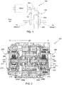
Fig. 1 provides a simplified side view of an electric vehicle powertrain in accordance with the prior art; -
Fig. 2 provides a cross-sectional view of a powertrain assembly in accordance with the invention; -
Fig. 3 provides a more detailed cross-sectional view of the stator shown inFig. 2 ; -
Fig. 4 provides a cross-sectional view of a portion of the stator, where the view provided byFig. 4 is orthogonal to the views shown inFigs. 2 and3 ; -
Fig. 5 illustrates the CV joint coupling to the planetary gear assembly in a conventional powertrain; -
Fig. 6 illustrates the means used to couple the CV joint to the planetary gear assembly in the powertrain of the invention; -
Fig. 7 provides a second cross-sectional view of the assembly illustrated inFig. 6 ; -
Fig. 8 illustrates a conventional rotor mounting configuration; and -
Fig. 9 provides a detailed perspective view of the rotor assembly of the powertrain shown inFig. 2 . - As used herein, the singular forms "a", "an" and "the" are intended to include the plural forms as well, unless the context clearly indicates otherwise. The terms "comprises", "comprising", "includes", and/or "including", as used herein, specify the presence of stated features, integers, steps, operations, elements, and/or components, but do not preclude the presence or addition of one or more other features, integers, steps, operations, elements, components, and/or groups thereof. As used herein, the term "and/or" and the symbol "/" are meant to include any and all combinations of one or more of the associated listed items. Additionally, while the terms first, second, etc. may be used herein to describe various steps or calculations, these steps or calculations should not be limited by these terms, rather these terms are only used to distinguish one step or calculation from another. For example, a first calculation could be termed a second calculation; similarly a first step could be termed a second step; similarly a first component could be termed a second component, all without departing from the scope of this disclosure.
-
Fig. 1 provides a side view of a commonly employedelectric vehicle powertrain 100. For purposes of clarity, this figure does not show gear teeth. As shown,input gear 101 is coupled todifferential gear 103 viaidler gear assembly 105. While this configuration is relatively straightforward to design and manufacture, it requires considerable volume. In order to reduce powertrain volume, a preferable configuration coaxially aligns the traction motor with the drive wheel axes. While this configuration is easily adapted to a rear wheel drive vehicle, its application to a front wheel drive vehicle is considerably more difficult given the volume constraints placed on the powertrain by the steering and suspension linkage assemblies. - While the powertrain configuration of a planetary-differential-planetary (i.e., a PDP configuration) is a known configuration, to date it has been used in low speed motor proportion designs. In this type of design there is a significant distance between the rotor lamination and the rotor shaft, resulting in a lower vehicle maximum speed. If one attempts to make up for the loss of top speed using a suitable gear reduction, then acceleration is reduced. The inventors of the present design have determined via extensive analyses that a high speed motor proportion design is preferable over a low speed motor proportion design in order to achieve a more favorable range of vehicle speeds while still maintaining adequate vehicle acceleration. Accordingly, the goal of the present invention is to configure a PDP powertrain assembly using a high speed motor proportion design, i.e., one in which the rotor lamination is directly connected to the rotor shaft, while still achieving a short overall width.
-
Fig. 2 provides a cross-sectional view of apowertrain assembly 200 designed in accordance with the invention,assembly 200 achieving a shortoverall width 201, wherewidth 201 is measured between thebottom surfaces 203 of the two constant velocity (i.e., CV)joint components 205. As shown, thehollow rotor shaft 207 is directly connected to the rotor lamination stack in order to achieve the high speed motor proportion configuration as desired. Although not a requirement of the invention, in the preferred embodiment illustrated inFig. 2 the lamination stack is comprised of fourlamination layers 209A-209D. Contained withinrotor shaft 207 is thedifferential gear assembly 211. - Surrounding the rotor lamination stack is
stator 213. Visible in this view are thestator windings 215 that extend from either end of the stator.Fig. 3 provides a more detailed cross-sectional view ofstator 213 than that provided byFig. 2 , whileFig. 4 provides an orthogonal cross-sectional view of a portion ofstator 213. As shown inFig. 4 , theslots 401 within thestator 213 are filled withstator wire 403. Preferably and as shown,stator wire 403 has a rectangular cross-section. The use of rectangular stator wire rather than round stator wire reduces manufacturing tolerance variations. As a result, the amount that the stator windings extend out from either end of the stator, i.e.,dimension 301, is less than that required when the stator wire has a circular cross-section. This, in turn, allows a further reduction in theoverall width 201 of the powertrain assembly to be achieved. - In a conventional PDP powertrain configuration such as the one illustrated in
Fig. 5 , the driven (i.e., powered)portion 501 of the CV joint includes the CVjoint housing 503 and a mountingcollar 505. Mountingcollar 505 is coupled to the planetarygear output shaft 507 of theplanetary gear assembly 509.CV mounting collar 505 is supported by acarrier bearing 511. - In contrast to the conventional means of supporting the CV joint, and as illustrated in
Figs. 2 and6 , the present invention utilizes a CVjoint component 601 that is integrated into theplanetary gear assembly 603. As shown, the CVjoint component 601 includes both a CVjoint housing member 605 that is integral to the CV joint component, and a plurality of planetarygear carrier members 607 that are integral to the CV Joint. By making the planetary gear carrier integral to the CV joint, theoverall width 201 of the powertrain assembly can be further decreased. Furthermore, as a result of this arrangement the CVjoint housing member 605 can be configured to fall within theplane 609 defined by CV jointcarrier bearing assembly 611 as shown. Thus this design decreases powertrain width while simultaneously providing improved CV joint support.Fig. 7 provides a second cross-sectional view of the assembly shown inFig. 6 , this view including a second CVjoint housing member 701, CVjoint boot 703, andoutput drive shaft 705. - In a conventional non-active core electric motor, such as that illustrated in
Fig. 8 , therotor shaft 801 is supported by a pair ofcarrier bearings 803. As shown, theinner race 805 of each bearing 803 is fixed to the rotor shaft while theouter race 807 is held stationary withinhousing members 809. Due to this arrangement, extra space is required to house the bearings, that additional space being axial, radial, or both. This arrangement can be especially problematic in an electric motor utilizing an active core, i.e., where the differential is constructed within the rotor shaft (see, for example, 2), since in this type of arrangement a relatively large, hollow rotor shaft is required. Additionally in an active core electric motor, this bearing arrangement limits the allowable rpm speed given the larger shaft size. To overcome these limitations and achieve a more compact powertrain, the present invention utilizes an inside-out bearing arrangement. - Referring to
Fig. 2 ,assembly 200 mounts therotor carrier bearings 217 inside therotor shaft 207, rather than mounting the bearings to the exterior of the rotor shaft as in a conventional active core powertrain. This eliminates the need for additional volume to house the bearings where that volumeimpacts powertrain width 201. In this configuration it is theouter race 219 that is fixed to the rotor shaft and theinner race 221 that is stationary and fixed tohousing member 223. In addition to minimizing, if not altogether eliminating, the impact of the rotor bearings on the powertrain width, this configuration also reduces the overall size of the bearings resulting in an increase in the allowable rpm speed. - As an electric motor operates, and regardless of whether the motor has an active or non-active core, a variety of forces act on the rotor (e.g., centripetal force, reactive centrifugal force). These forces can be especially problematic in an active-core motor due to the size of the hollow rotor shaft within which is mounted the differential. To help minimize the effects of these forces on the rotor, and as illustrated in
Fig. 9 , preferably lamination layers 209A-209D are held between a pair of rotorassembly end plates 901. The entire rotor assembly, i.e., lamination layers 209A-209D andend plates 901, are clamped together using a plurality of axially mounted rivets 903. In addition, the preferred rotor assembly bonds therotor magnets 905 to the corresponding lamination layers using a thermoset bonding agent.Rivets 903, especially when used in combination with the process of bonding the rotor magnets to the lamination layers, results in a very robust and rigid rotor assembly capable of handling the rotational speeds, temperatures and loads required of a high performance powertrain. - Systems and methods have been described in general terms as an aid to understanding details of the invention. In some instances, well-known structures, materials, and/or operations have not been specifically shown or described in detail to avoid obscuring aspects of the invention. In other instances, specific details have been given in order to provide a thorough understanding of the invention. One skilled in the relevant art will recognize that the invention may be embodied in other specific forms, for example to adapt to a particular system or apparatus or situation or material or component, without departing from the scope of the appended claims.
Claims (7)
- A powertrain assembly, comprising:an electric motor, said electric motor comprising:a hollow rotor shaft (207); anda rotor lamination stack containing a plurality of permanent magnets, wherein said rotor lamination stack encircles said hollow rotor shaft (207), and wherein said rotor lamination stack is attached directly to said hollow rotor shaft (207);a differential gear assembly (211) mounted within said hollow rotor shaft (207), wherein a first output shaft coupled to said differential gear assembly exits said hollow rotor shaft from a first end of said hollow rotor shaft, wherein a second output shaft coupled to said differential gear assembly exits said hollow rotor shaft from a second end of said hollow rotor shaft, and wherein said second end of said hollow rotor shaft is distal from said first end of said hollow rotor shaft;a first planetary gear assembly (603) coupled to said first output shaft, wherein said first planetary gear assembly (603) is coaxially aligned with said hollow rotor shaft (207), said first planetary gear assembly (603) comprising a first planetary gear carrier (607); anda second planetary gear assembly coupled to said second output shaft, wherein said second planetary gear assembly is coaxially aligned with said hollow rotor shaft (207), said second planetary gear assembly comprising a second planetary gear carrier;characterized bya first constant velocity (CV) joint component (205; 601), said first CV joint component (205; 601) further comprising a first CV joint housing member (605), wherein said first planetary gear carrier (607) is integral to said first CV joint component (205; 601); anda second CV joint component (205), said second CV joint component (205) further comprising a second CV joint housing member, wherein said second planetary gear carrier is integral to said second CV joint component.
- The powertrain assembly of claim 1, further comprising:a first CV joint carrier bearing assembly (611), wherein said first CV joint housing member (605) is located within the plane (609) defined by said first CV joint carrier bearing assembly (611); anda second CV joint carrier bearing assembly, wherein said second CV joint housing member is located within the plane defined by said second CV joint carrier bearing assembly.
- The powertrain assembly of claim 1, said first planetary gear carrier comprising a first plurality of planetary gear carrier members (607) extending from a rear surface of said first CV joint housing member (605), and said second planetary gear carrier comprising a second plurality of planetary gear carrier members extending from a rear surface of said second CV joint housing member.
- The powertrain assembly of claim 1, further comprising:a first rotor carrier bearing mounted within a first portion of said hollow rotor shaft (207), wherein an outer bearing race (219) of said first rotor carrier bearing is mounted to an inner rotor surface, wherein an inner bearing race (217) of said first rotor carrier bearing is mounted to a first powertrain assembly housing member, and wherein said first powertrain assembly housing member extends into said hollow rotor shaft (207); anda second rotor carrier bearing mounted within a second portion of said hollow rotor shaft (207), wherein an outer bearing race (219) of said second rotor carrier bearing is mounted to said inner rotor surface, wherein an inner bearing race (217) of said second rotor carrier bearing is mounted to a second powertrain assembly housing member, and wherein said second powertrain assembly housing member extends into said hollow rotor shaft (207).
- The powertrain assembly of any one of claims 1-4, said electric motor further comprising a stator (213) with a plurality of slots (401), wherein a plurality of windings occupy said plurality of slots (401), said plurality of windings comprised of stator wire (403) with a rectangular cross-section.
- The powertrain assembly of any one of claims 1-4, said rotor lamination stack further comprising:a plurality of lamination layers (209A-209D); anda plurality of rivets, said plurality of lamination layers clamped together with said plurality of rivets (903).
- The powertrain assembly of claim 6, said rotor lamination stack further comprising a first rotor assembly end plate (901) and a second rotor assembly end plate (901), said plurality of lamination layers (209A-209D) interposed between said first and second rotor assembly end plates (901), and wherein said plurality of rivets (903) clamp together said first rotor assembly end plate (901), said plurality of lamination layers (209A-209D), and said second rotor assembly end plate (901).
Applications Claiming Priority (2)
| Application Number | Priority Date | Filing Date | Title |
|---|---|---|---|
| US201862766523P | 2018-10-23 | 2018-10-23 | |
| US16/181,612 US10797562B2 (en) | 2018-10-23 | 2018-11-06 | High torque and power density drive system with shortened overall width |
Publications (2)
| Publication Number | Publication Date |
|---|---|
| EP3644479A1 EP3644479A1 (en) | 2020-04-29 |
| EP3644479B1 true EP3644479B1 (en) | 2021-09-15 |
Family
ID=68084677
Family Applications (1)
| Application Number | Title | Priority Date | Filing Date |
|---|---|---|---|
| EP19200232.7A Active EP3644479B1 (en) | 2018-10-23 | 2019-09-27 | High torque and power density drive system with shortened overall width |
Country Status (5)
| Country | Link |
|---|---|
| US (1) | US10797562B2 (en) |
| EP (1) | EP3644479B1 (en) |
| JP (1) | JP7056845B2 (en) |
| KR (1) | KR102278302B1 (en) |
| CN (2) | CN111086376B (en) |
Families Citing this family (19)
| Publication number | Priority date | Publication date | Assignee | Title |
|---|---|---|---|---|
| US10797562B2 (en) * | 2018-10-23 | 2020-10-06 | Atieva, Inc. | High torque and power density drive system with shortened overall width |
| US11735988B2 (en) * | 2019-01-31 | 2023-08-22 | General Electric Company | Dual rotor electric machine |
| US11025113B2 (en) * | 2019-06-26 | 2021-06-01 | Atieva, Inc. | Hybrid rotor assembly |
| SK289114B6 (en) * | 2020-07-20 | 2023-09-13 | Roman Procházka | Propulsion with three electric motors, two planetary gears and a differential |
| DE102021127341A1 (en) | 2021-10-21 | 2023-04-27 | Schaeffler Technologies AG & Co. KG | Electric final drive with a differential lock |
| DE102021127349A1 (en) | 2021-10-21 | 2023-04-27 | Schaeffler Technologies AG & Co. KG | Electric final drive with a power transfer case |
| WO2023074806A1 (en) * | 2021-10-29 | 2023-05-04 | 株式会社アイシン | Drive transmission device for vehicle |
| EP4577755A1 (en) | 2022-08-26 | 2025-07-02 | Atieva, Inc. | Rotation direction driven two-speed transmission |
| US12456893B2 (en) | 2022-08-29 | 2025-10-28 | Atieva, Inc. | Electric motor with unvarnished end winding for stator |
| US11890930B1 (en) | 2022-09-07 | 2024-02-06 | Dana Automotive Systems Group, Llc | Systems for electric powertrain differential |
| EP4387060A1 (en) * | 2022-12-16 | 2024-06-19 | Rimac Technology LLC | Drive unit |
| US12104657B2 (en) | 2022-12-19 | 2024-10-01 | Atieva, Inc. | Axle decoupler system with mechanical synchronizer |
| US12549068B2 (en) | 2023-03-27 | 2026-02-10 | Garrett Transportation I Inc. | E-machine system with rotor arrangement in fluid circuit for cooling and lubrication |
| WO2025049666A1 (en) | 2023-08-30 | 2025-03-06 | Borgwarner Inc. | Drive module assembly |
| WO2025049723A1 (en) | 2023-08-30 | 2025-03-06 | Borgwarner Inc. | Drive module assembly |
| US12592591B2 (en) | 2023-09-14 | 2026-03-31 | Atieva, Inc. | Electric motor with insulated permanent magnet |
| US12337664B2 (en) | 2023-09-27 | 2025-06-24 | Atieva, Inc. | Seal retention clip for vehicle window assembly |
| FR3155384B1 (en) | 2023-11-11 | 2025-09-26 | Michel Raoul | Electric powertrain with differential integrated into the wound rotor of the electric machine. |
| US12110950B1 (en) | 2023-12-01 | 2024-10-08 | Atieva, Inc. | Compact two-speed transmission with compound planetary stage |
Family Cites Families (19)
| Publication number | Priority date | Publication date | Assignee | Title |
|---|---|---|---|---|
| JPH04339024A (en) * | 1991-02-01 | 1992-11-26 | Mazda Motor Corp | Power transmission device for vehicle |
| DE4421428C1 (en) * | 1994-06-18 | 1995-07-27 | Fichtel & Sachs Ag | Planetary gearing esp. for electric drive of road vehicle wheel |
| JP2003127682A (en) * | 2001-10-22 | 2003-05-08 | Fuji Heavy Ind Ltd | Vehicle drive system |
| US8860278B2 (en) | 2007-07-27 | 2014-10-14 | GM Global Technology Operations LLC | Stator assembly for belt alternator starter motor generator for hybrid vehicles |
| JP2010263761A (en) | 2009-05-07 | 2010-11-18 | Planet Techno:Kk | Motor apparatus with built-in transmission |
| CN102612614B (en) * | 2009-11-16 | 2015-05-13 | 雷米技术有限公司 | Electric motor with planetary gear set |
| SE534296C2 (en) * | 2009-11-24 | 2011-07-05 | Bae Systems Haegglunds Ab | Electric drive system |
| US20120129644A1 (en) | 2010-11-19 | 2012-05-24 | Remy Technologies, L.L.C. | Transmission member including an electric motor having an integrated differential |
| DE102011100816A1 (en) * | 2011-05-06 | 2012-11-08 | Audi Ag | Drive assembly used for driving electric machine e.g. electric motor of e.g. electrically-driven vehicle, has translation mechanism and differential that are integrated in annular rotor |
| JP2012240599A (en) * | 2011-05-23 | 2012-12-10 | Honda Motor Co Ltd | Drive device of vehicle with motor |
| US8967004B2 (en) * | 2012-06-11 | 2015-03-03 | Remy Technologies Llc | Armature with torque limiter for engine starter |
| CN202716729U (en) * | 2012-06-21 | 2013-02-06 | 联合汽车电子有限公司 | Integrated type power driving device of motor and speed changing box for electric vehicle |
| KR101437546B1 (en) * | 2012-09-13 | 2014-09-04 | 현대모비스 주식회사 | Stator assembly, axial flux permanent magnet motor and method for manufacturing stator |
| JP5728038B2 (en) | 2013-01-29 | 2015-06-03 | 株式会社豊田自動織機 | Rotor for rotating electrical machine and method for manufacturing the same |
| CA2907359C (en) * | 2013-03-15 | 2021-08-17 | Linamar Corporation | Hybrid axle assembly for a motor vehicle |
| CN205945295U (en) * | 2014-02-20 | 2017-02-08 | 三菱电机株式会社 | Rotor, permanent magnet motor including the same, fluid machine including permanent magnet motor |
| JP6540038B2 (en) * | 2015-01-22 | 2019-07-10 | 株式会社デンソー | Outer rotor type rotating electric machine |
| PL3465889T3 (en) * | 2016-06-07 | 2021-10-25 | Tesla, Inc. | Electric motor rotor discharge protection |
| US10797562B2 (en) * | 2018-10-23 | 2020-10-06 | Atieva, Inc. | High torque and power density drive system with shortened overall width |
-
2018
- 2018-11-06 US US16/181,612 patent/US10797562B2/en active Active
-
2019
- 2019-09-27 EP EP19200232.7A patent/EP3644479B1/en active Active
- 2019-10-07 JP JP2019184764A patent/JP7056845B2/en active Active
- 2019-10-16 KR KR1020190128358A patent/KR102278302B1/en not_active Expired - Fee Related
- 2019-10-23 CN CN201911010323.8A patent/CN111086376B/en not_active Expired - Fee Related
- 2019-10-23 CN CN201921786135.XU patent/CN211054902U/en not_active Expired - Fee Related
Also Published As
| Publication number | Publication date |
|---|---|
| CN211054902U (en) | 2020-07-21 |
| US10797562B2 (en) | 2020-10-06 |
| JP7056845B2 (en) | 2022-04-19 |
| CN111086376B (en) | 2023-06-20 |
| EP3644479A1 (en) | 2020-04-29 |
| KR102278302B1 (en) | 2021-07-20 |
| JP2020066426A (en) | 2020-04-30 |
| KR20200047339A (en) | 2020-05-07 |
| US20200127532A1 (en) | 2020-04-23 |
| CN111086376A (en) | 2020-05-01 |
Similar Documents
| Publication | Publication Date | Title |
|---|---|---|
| EP3644479B1 (en) | High torque and power density drive system with shortened overall width | |
| US11394270B2 (en) | Differential for an active core electric motor having pin with friction fit | |
| AU2007219849B2 (en) | Securing structure of stator and electric vehicle | |
| CN204451974U (en) | The integrated driving assembly of battery-driven car | |
| US10581306B2 (en) | Power system having two motors | |
| WO2018090485A1 (en) | Coaxial multi-motor drive system and vehicle provided with same | |
| US20200127508A1 (en) | Low Cogging Torque, High Torque Density Traction Motor | |
| US20080061525A1 (en) | Vehicular wheel assembly | |
| CN103158527A (en) | Power delivery device for vehicle | |
| WO2010095610A1 (en) | Hybrid electric vehicle | |
| US20240399851A1 (en) | Electrically driven axle | |
| KR20140131522A (en) | Electrically driven vehicle drive axle arrangement | |
| US8534162B2 (en) | Drive unit for hybrid vehicle | |
| JP3007471B2 (en) | Electric vehicle parking device | |
| CN118355211A (en) | Drive device | |
| CN101277043B (en) | Frequency control motor and generating set for hybrid vehicle | |
| US20140302958A1 (en) | Drive device having an electrical drive machine | |
| KR102930007B1 (en) | Power transmission device | |
| CN219236735U (en) | Distributed power unit, electric vehicle and aircraft | |
| CN102545470A (en) | Variable-frequency speed control motor for hybrid electric vehicle | |
| US20260078814A1 (en) | E-beam with stepped and simple planetary gearsets | |
| CN202435188U (en) | Variable-frequency and variable-speed motor for hybrid vehicle | |
| KR20120059164A (en) | Vehicle wheel drive apparatus of shaft separate type |
Legal Events
| Date | Code | Title | Description |
|---|---|---|---|
| PUAI | Public reference made under article 153(3) epc to a published international application that has entered the european phase |
Free format text: ORIGINAL CODE: 0009012 |
|
| STAA | Information on the status of an ep patent application or granted ep patent |
Free format text: STATUS: REQUEST FOR EXAMINATION WAS MADE |
|
| 17P | Request for examination filed |
Effective date: 20190927 |
|
| AK | Designated contracting states |
Kind code of ref document: A1 Designated state(s): AL AT BE BG CH CY CZ DE DK EE ES FI FR GB GR HR HU IE IS IT LI LT LU LV MC MK MT NL NO PL PT RO RS SE SI SK SM TR |
|
| AX | Request for extension of the european patent |
Extension state: BA ME |
|
| RBV | Designated contracting states (corrected) |
Designated state(s): AL AT BE BG CH CY CZ DE DK EE ES FI FR GB GR HR HU IE IS IT LI LT LU LV MC MK MT NL NO PL PT RO RS SE SI SK SM TR |
|
| GRAP | Despatch of communication of intention to grant a patent |
Free format text: ORIGINAL CODE: EPIDOSNIGR1 |
|
| STAA | Information on the status of an ep patent application or granted ep patent |
Free format text: STATUS: GRANT OF PATENT IS INTENDED |
|
| INTG | Intention to grant announced |
Effective date: 20210429 |
|
| GRAS | Grant fee paid |
Free format text: ORIGINAL CODE: EPIDOSNIGR3 |
|
| GRAA | (expected) grant |
Free format text: ORIGINAL CODE: 0009210 |
|
| STAA | Information on the status of an ep patent application or granted ep patent |
Free format text: STATUS: THE PATENT HAS BEEN GRANTED |
|
| AK | Designated contracting states |
Kind code of ref document: B1 Designated state(s): AL AT BE BG CH CY CZ DE DK EE ES FI FR GB GR HR HU IE IS IT LI LT LU LV MC MK MT NL NO PL PT RO RS SE SI SK SM TR |
|
| REG | Reference to a national code |
Ref country code: CH Ref legal event code: EP |
|
| REG | Reference to a national code |
Ref country code: DE Ref legal event code: R096 Ref document number: 602019007688 Country of ref document: DE |
|
| REG | Reference to a national code |
Ref country code: IE Ref legal event code: FG4D |
|
| REG | Reference to a national code |
Ref country code: AT Ref legal event code: REF Ref document number: 1431290 Country of ref document: AT Kind code of ref document: T Effective date: 20211015 |
|
| REG | Reference to a national code |
Ref country code: NL Ref legal event code: FP |
|
| REG | Reference to a national code |
Ref country code: LT Ref legal event code: MG9D |
|
| PG25 | Lapsed in a contracting state [announced via postgrant information from national office to epo] |
Ref country code: FI Free format text: LAPSE BECAUSE OF FAILURE TO SUBMIT A TRANSLATION OF THE DESCRIPTION OR TO PAY THE FEE WITHIN THE PRESCRIBED TIME-LIMIT Effective date: 20210915 Ref country code: RS Free format text: LAPSE BECAUSE OF FAILURE TO SUBMIT A TRANSLATION OF THE DESCRIPTION OR TO PAY THE FEE WITHIN THE PRESCRIBED TIME-LIMIT Effective date: 20210915 Ref country code: SE Free format text: LAPSE BECAUSE OF FAILURE TO SUBMIT A TRANSLATION OF THE DESCRIPTION OR TO PAY THE FEE WITHIN THE PRESCRIBED TIME-LIMIT Effective date: 20210915 Ref country code: HR Free format text: LAPSE BECAUSE OF FAILURE TO SUBMIT A TRANSLATION OF THE DESCRIPTION OR TO PAY THE FEE WITHIN THE PRESCRIBED TIME-LIMIT Effective date: 20210915 Ref country code: NO Free format text: LAPSE BECAUSE OF FAILURE TO SUBMIT A TRANSLATION OF THE DESCRIPTION OR TO PAY THE FEE WITHIN THE PRESCRIBED TIME-LIMIT Effective date: 20211215 Ref country code: LT Free format text: LAPSE BECAUSE OF FAILURE TO SUBMIT A TRANSLATION OF THE DESCRIPTION OR TO PAY THE FEE WITHIN THE PRESCRIBED TIME-LIMIT Effective date: 20210915 Ref country code: BG Free format text: LAPSE BECAUSE OF FAILURE TO SUBMIT A TRANSLATION OF THE DESCRIPTION OR TO PAY THE FEE WITHIN THE PRESCRIBED TIME-LIMIT Effective date: 20211215 |
|
| REG | Reference to a national code |
Ref country code: AT Ref legal event code: MK05 Ref document number: 1431290 Country of ref document: AT Kind code of ref document: T Effective date: 20210915 |
|
| PG25 | Lapsed in a contracting state [announced via postgrant information from national office to epo] |
Ref country code: LV Free format text: LAPSE BECAUSE OF FAILURE TO SUBMIT A TRANSLATION OF THE DESCRIPTION OR TO PAY THE FEE WITHIN THE PRESCRIBED TIME-LIMIT Effective date: 20210915 Ref country code: GR Free format text: LAPSE BECAUSE OF FAILURE TO SUBMIT A TRANSLATION OF THE DESCRIPTION OR TO PAY THE FEE WITHIN THE PRESCRIBED TIME-LIMIT Effective date: 20211216 |
|
| PG25 | Lapsed in a contracting state [announced via postgrant information from national office to epo] |
Ref country code: AT Free format text: LAPSE BECAUSE OF FAILURE TO SUBMIT A TRANSLATION OF THE DESCRIPTION OR TO PAY THE FEE WITHIN THE PRESCRIBED TIME-LIMIT Effective date: 20210915 |
|
| REG | Reference to a national code |
Ref country code: BE Ref legal event code: MM Effective date: 20210930 |
|
| PG25 | Lapsed in a contracting state [announced via postgrant information from national office to epo] |
Ref country code: IS Free format text: LAPSE BECAUSE OF FAILURE TO SUBMIT A TRANSLATION OF THE DESCRIPTION OR TO PAY THE FEE WITHIN THE PRESCRIBED TIME-LIMIT Effective date: 20220115 Ref country code: SM Free format text: LAPSE BECAUSE OF FAILURE TO SUBMIT A TRANSLATION OF THE DESCRIPTION OR TO PAY THE FEE WITHIN THE PRESCRIBED TIME-LIMIT Effective date: 20210915 Ref country code: SK Free format text: LAPSE BECAUSE OF FAILURE TO SUBMIT A TRANSLATION OF THE DESCRIPTION OR TO PAY THE FEE WITHIN THE PRESCRIBED TIME-LIMIT Effective date: 20210915 Ref country code: RO Free format text: LAPSE BECAUSE OF FAILURE TO SUBMIT A TRANSLATION OF THE DESCRIPTION OR TO PAY THE FEE WITHIN THE PRESCRIBED TIME-LIMIT Effective date: 20210915 Ref country code: PT Free format text: LAPSE BECAUSE OF FAILURE TO SUBMIT A TRANSLATION OF THE DESCRIPTION OR TO PAY THE FEE WITHIN THE PRESCRIBED TIME-LIMIT Effective date: 20220117 Ref country code: PL Free format text: LAPSE BECAUSE OF FAILURE TO SUBMIT A TRANSLATION OF THE DESCRIPTION OR TO PAY THE FEE WITHIN THE PRESCRIBED TIME-LIMIT Effective date: 20210915 Ref country code: ES Free format text: LAPSE BECAUSE OF FAILURE TO SUBMIT A TRANSLATION OF THE DESCRIPTION OR TO PAY THE FEE WITHIN THE PRESCRIBED TIME-LIMIT Effective date: 20210915 Ref country code: EE Free format text: LAPSE BECAUSE OF FAILURE TO SUBMIT A TRANSLATION OF THE DESCRIPTION OR TO PAY THE FEE WITHIN THE PRESCRIBED TIME-LIMIT Effective date: 20210915 Ref country code: CZ Free format text: LAPSE BECAUSE OF FAILURE TO SUBMIT A TRANSLATION OF THE DESCRIPTION OR TO PAY THE FEE WITHIN THE PRESCRIBED TIME-LIMIT Effective date: 20210915 Ref country code: AL Free format text: LAPSE BECAUSE OF FAILURE TO SUBMIT A TRANSLATION OF THE DESCRIPTION OR TO PAY THE FEE WITHIN THE PRESCRIBED TIME-LIMIT Effective date: 20210915 |
|
| REG | Reference to a national code |
Ref country code: DE Ref legal event code: R097 Ref document number: 602019007688 Country of ref document: DE |
|
| PG25 | Lapsed in a contracting state [announced via postgrant information from national office to epo] |
Ref country code: MC Free format text: LAPSE BECAUSE OF FAILURE TO SUBMIT A TRANSLATION OF THE DESCRIPTION OR TO PAY THE FEE WITHIN THE PRESCRIBED TIME-LIMIT Effective date: 20210915 |
|
| PLBE | No opposition filed within time limit |
Free format text: ORIGINAL CODE: 0009261 |
|
| STAA | Information on the status of an ep patent application or granted ep patent |
Free format text: STATUS: NO OPPOSITION FILED WITHIN TIME LIMIT |
|
| PG25 | Lapsed in a contracting state [announced via postgrant information from national office to epo] |
Ref country code: LU Free format text: LAPSE BECAUSE OF NON-PAYMENT OF DUE FEES Effective date: 20210927 Ref country code: IE Free format text: LAPSE BECAUSE OF NON-PAYMENT OF DUE FEES Effective date: 20210927 Ref country code: DK Free format text: LAPSE BECAUSE OF FAILURE TO SUBMIT A TRANSLATION OF THE DESCRIPTION OR TO PAY THE FEE WITHIN THE PRESCRIBED TIME-LIMIT Effective date: 20210915 Ref country code: BE Free format text: LAPSE BECAUSE OF NON-PAYMENT OF DUE FEES Effective date: 20210930 |
|
| 26N | No opposition filed |
Effective date: 20220616 |
|
| PG25 | Lapsed in a contracting state [announced via postgrant information from national office to epo] |
Ref country code: SI Free format text: LAPSE BECAUSE OF FAILURE TO SUBMIT A TRANSLATION OF THE DESCRIPTION OR TO PAY THE FEE WITHIN THE PRESCRIBED TIME-LIMIT Effective date: 20210915 |
|
| PG25 | Lapsed in a contracting state [announced via postgrant information from national office to epo] |
Ref country code: IT Free format text: LAPSE BECAUSE OF FAILURE TO SUBMIT A TRANSLATION OF THE DESCRIPTION OR TO PAY THE FEE WITHIN THE PRESCRIBED TIME-LIMIT Effective date: 20210915 |
|
| REG | Reference to a national code |
Ref country code: CH Ref legal event code: PL |
|
| PG25 | Lapsed in a contracting state [announced via postgrant information from national office to epo] |
Ref country code: CY Free format text: LAPSE BECAUSE OF FAILURE TO SUBMIT A TRANSLATION OF THE DESCRIPTION OR TO PAY THE FEE WITHIN THE PRESCRIBED TIME-LIMIT Effective date: 20210915 |
|
| PG25 | Lapsed in a contracting state [announced via postgrant information from national office to epo] |
Ref country code: LI Free format text: LAPSE BECAUSE OF NON-PAYMENT OF DUE FEES Effective date: 20220930 Ref country code: HU Free format text: LAPSE BECAUSE OF FAILURE TO SUBMIT A TRANSLATION OF THE DESCRIPTION OR TO PAY THE FEE WITHIN THE PRESCRIBED TIME-LIMIT; INVALID AB INITIO Effective date: 20190927 Ref country code: CH Free format text: LAPSE BECAUSE OF NON-PAYMENT OF DUE FEES Effective date: 20220930 |
|
| P01 | Opt-out of the competence of the unified patent court (upc) registered |
Effective date: 20230707 |
|
| PGFP | Annual fee paid to national office [announced via postgrant information from national office to epo] |
Ref country code: NL Payment date: 20230921 Year of fee payment: 5 |
|
| PGFP | Annual fee paid to national office [announced via postgrant information from national office to epo] |
Ref country code: FR Payment date: 20230928 Year of fee payment: 5 |
|
| PG25 | Lapsed in a contracting state [announced via postgrant information from national office to epo] |
Ref country code: MK Free format text: LAPSE BECAUSE OF FAILURE TO SUBMIT A TRANSLATION OF THE DESCRIPTION OR TO PAY THE FEE WITHIN THE PRESCRIBED TIME-LIMIT Effective date: 20210915 |
|
| PG25 | Lapsed in a contracting state [announced via postgrant information from national office to epo] |
Ref country code: TR Free format text: LAPSE BECAUSE OF FAILURE TO SUBMIT A TRANSLATION OF THE DESCRIPTION OR TO PAY THE FEE WITHIN THE PRESCRIBED TIME-LIMIT Effective date: 20210915 |
|
| PG25 | Lapsed in a contracting state [announced via postgrant information from national office to epo] |
Ref country code: MT Free format text: LAPSE BECAUSE OF FAILURE TO SUBMIT A TRANSLATION OF THE DESCRIPTION OR TO PAY THE FEE WITHIN THE PRESCRIBED TIME-LIMIT Effective date: 20210915 |
|
| REG | Reference to a national code |
Ref country code: NL Ref legal event code: MM Effective date: 20241001 |
|
| PG25 | Lapsed in a contracting state [announced via postgrant information from national office to epo] |
Ref country code: NL Free format text: LAPSE BECAUSE OF NON-PAYMENT OF DUE FEES Effective date: 20241001 |
|
| PG25 | Lapsed in a contracting state [announced via postgrant information from national office to epo] |
Ref country code: FR Free format text: LAPSE BECAUSE OF NON-PAYMENT OF DUE FEES Effective date: 20240930 |
|
| PGFP | Annual fee paid to national office [announced via postgrant information from national office to epo] |
Ref country code: DE Payment date: 20250919 Year of fee payment: 7 |
|
| PGFP | Annual fee paid to national office [announced via postgrant information from national office to epo] |
Ref country code: GB Payment date: 20250923 Year of fee payment: 7 |
|
| REG | Reference to a national code |
Ref country code: DE Ref legal event code: R082 Ref document number: 602019007688 Country of ref document: DE Representative=s name: GULDE & PARTNER PATENT- UND RECHTSANWALTSKANZL, DE |