EP3644446A1 - Conductive terminal and connector assembly - Google Patents
Conductive terminal and connector assembly Download PDFInfo
- Publication number
- EP3644446A1 EP3644446A1 EP19204553.2A EP19204553A EP3644446A1 EP 3644446 A1 EP3644446 A1 EP 3644446A1 EP 19204553 A EP19204553 A EP 19204553A EP 3644446 A1 EP3644446 A1 EP 3644446A1
- Authority
- EP
- European Patent Office
- Prior art keywords
- conductive terminal
- insertion direction
- wire
- terminal according
- conductor
- Prior art date
- Legal status (The legal status is an assumption and is not a legal conclusion. Google has not performed a legal analysis and makes no representation as to the accuracy of the status listed.)
- Granted
Links
Images





Classifications
-
- H—ELECTRICITY
- H01—ELECTRIC ELEMENTS
- H01R—ELECTRICALLY-CONDUCTIVE CONNECTIONS; STRUCTURAL ASSOCIATIONS OF A PLURALITY OF MUTUALLY-INSULATED ELECTRICAL CONNECTING ELEMENTS; COUPLING DEVICES; CURRENT COLLECTORS
- H01R4/00—Electrically-conductive connections between two or more conductive members in direct contact, i.e. touching one another; Means for effecting or maintaining such contact; Electrically-conductive connections having two or more spaced connecting locations for conductors and using contact members penetrating insulation
- H01R4/28—Clamped connections, spring connections
-
- H—ELECTRICITY
- H01—ELECTRIC ELEMENTS
- H01R—ELECTRICALLY-CONDUCTIVE CONNECTIONS; STRUCTURAL ASSOCIATIONS OF A PLURALITY OF MUTUALLY-INSULATED ELECTRICAL CONNECTING ELEMENTS; COUPLING DEVICES; CURRENT COLLECTORS
- H01R13/00—Details of coupling devices of the kinds covered by groups H01R12/70 or H01R24/00 - H01R33/00
- H01R13/02—Contact members
- H01R13/20—Pins, blades, or sockets shaped, or provided with separate member, to retain co-operating parts together
-
- H—ELECTRICITY
- H01—ELECTRIC ELEMENTS
- H01R—ELECTRICALLY-CONDUCTIVE CONNECTIONS; STRUCTURAL ASSOCIATIONS OF A PLURALITY OF MUTUALLY-INSULATED ELECTRICAL CONNECTING ELEMENTS; COUPLING DEVICES; CURRENT COLLECTORS
- H01R12/00—Structural associations of a plurality of mutually-insulated electrical connecting elements, specially adapted for printed circuits, e.g. printed circuit boards [PCB], flat or ribbon cables, or like generally planar structures, e.g. terminal strips, terminal blocks; Coupling devices specially adapted for printed circuits, flat or ribbon cables, or like generally planar structures; Terminals specially adapted for contact with, or insertion into, printed circuits, flat or ribbon cables, or like generally planar structures
- H01R12/50—Fixed connections
- H01R12/51—Fixed connections for rigid printed circuits or like structures
- H01R12/515—Terminal blocks providing connections to wires or cables
-
- H—ELECTRICITY
- H01—ELECTRIC ELEMENTS
- H01R—ELECTRICALLY-CONDUCTIVE CONNECTIONS; STRUCTURAL ASSOCIATIONS OF A PLURALITY OF MUTUALLY-INSULATED ELECTRICAL CONNECTING ELEMENTS; COUPLING DEVICES; CURRENT COLLECTORS
- H01R12/00—Structural associations of a plurality of mutually-insulated electrical connecting elements, specially adapted for printed circuits, e.g. printed circuit boards [PCB], flat or ribbon cables, or like generally planar structures, e.g. terminal strips, terminal blocks; Coupling devices specially adapted for printed circuits, flat or ribbon cables, or like generally planar structures; Terminals specially adapted for contact with, or insertion into, printed circuits, flat or ribbon cables, or like generally planar structures
- H01R12/50—Fixed connections
- H01R12/51—Fixed connections for rigid printed circuits or like structures
- H01R12/55—Fixed connections for rigid printed circuits or like structures characterised by the terminals
- H01R12/57—Fixed connections for rigid printed circuits or like structures characterised by the terminals surface mounting terminals
-
- H—ELECTRICITY
- H01—ELECTRIC ELEMENTS
- H01R—ELECTRICALLY-CONDUCTIVE CONNECTIONS; STRUCTURAL ASSOCIATIONS OF A PLURALITY OF MUTUALLY-INSULATED ELECTRICAL CONNECTING ELEMENTS; COUPLING DEVICES; CURRENT COLLECTORS
- H01R12/00—Structural associations of a plurality of mutually-insulated electrical connecting elements, specially adapted for printed circuits, e.g. printed circuit boards [PCB], flat or ribbon cables, or like generally planar structures, e.g. terminal strips, terminal blocks; Coupling devices specially adapted for printed circuits, flat or ribbon cables, or like generally planar structures; Terminals specially adapted for contact with, or insertion into, printed circuits, flat or ribbon cables, or like generally planar structures
- H01R12/50—Fixed connections
- H01R12/51—Fixed connections for rigid printed circuits or like structures
- H01R12/55—Fixed connections for rigid printed circuits or like structures characterised by the terminals
- H01R12/58—Fixed connections for rigid printed circuits or like structures characterised by the terminals terminals for insertion into holes
-
- H—ELECTRICITY
- H01—ELECTRIC ELEMENTS
- H01R—ELECTRICALLY-CONDUCTIVE CONNECTIONS; STRUCTURAL ASSOCIATIONS OF A PLURALITY OF MUTUALLY-INSULATED ELECTRICAL CONNECTING ELEMENTS; COUPLING DEVICES; CURRENT COLLECTORS
- H01R12/00—Structural associations of a plurality of mutually-insulated electrical connecting elements, specially adapted for printed circuits, e.g. printed circuit boards [PCB], flat or ribbon cables, or like generally planar structures, e.g. terminal strips, terminal blocks; Coupling devices specially adapted for printed circuits, flat or ribbon cables, or like generally planar structures; Terminals specially adapted for contact with, or insertion into, printed circuits, flat or ribbon cables, or like generally planar structures
- H01R12/70—Coupling devices
- H01R12/7005—Guiding, mounting, polarizing or locking means; Extractors
-
- H—ELECTRICITY
- H01—ELECTRIC ELEMENTS
- H01R—ELECTRICALLY-CONDUCTIVE CONNECTIONS; STRUCTURAL ASSOCIATIONS OF A PLURALITY OF MUTUALLY-INSULATED ELECTRICAL CONNECTING ELEMENTS; COUPLING DEVICES; CURRENT COLLECTORS
- H01R12/00—Structural associations of a plurality of mutually-insulated electrical connecting elements, specially adapted for printed circuits, e.g. printed circuit boards [PCB], flat or ribbon cables, or like generally planar structures, e.g. terminal strips, terminal blocks; Coupling devices specially adapted for printed circuits, flat or ribbon cables, or like generally planar structures; Terminals specially adapted for contact with, or insertion into, printed circuits, flat or ribbon cables, or like generally planar structures
- H01R12/70—Coupling devices
- H01R12/71—Coupling devices for rigid printing circuits or like structures
- H01R12/712—Coupling devices for rigid printing circuits or like structures co-operating with the surface of the printed circuit or with a coupling device exclusively provided on the surface of the printed circuit
- H01R12/716—Coupling device provided on the PCB
-
- H—ELECTRICITY
- H01—ELECTRIC ELEMENTS
- H01R—ELECTRICALLY-CONDUCTIVE CONNECTIONS; STRUCTURAL ASSOCIATIONS OF A PLURALITY OF MUTUALLY-INSULATED ELECTRICAL CONNECTING ELEMENTS; COUPLING DEVICES; CURRENT COLLECTORS
- H01R13/00—Details of coupling devices of the kinds covered by groups H01R12/70 or H01R24/00 - H01R33/00
- H01R13/02—Contact members
- H01R13/15—Pins, blades or sockets having separate spring member for producing or increasing contact pressure
-
- H—ELECTRICITY
- H01—ELECTRIC ELEMENTS
- H01R—ELECTRICALLY-CONDUCTIVE CONNECTIONS; STRUCTURAL ASSOCIATIONS OF A PLURALITY OF MUTUALLY-INSULATED ELECTRICAL CONNECTING ELEMENTS; COUPLING DEVICES; CURRENT COLLECTORS
- H01R13/00—Details of coupling devices of the kinds covered by groups H01R12/70 or H01R24/00 - H01R33/00
- H01R13/62—Means for facilitating engagement or disengagement of coupling parts or for holding them in engagement
- H01R13/629—Additional means for facilitating engagement or disengagement of coupling parts, e.g. aligning or guiding means, levers, gas pressure electrical locking indicators, manufacturing tolerances
-
- H—ELECTRICITY
- H01—ELECTRIC ELEMENTS
- H01R—ELECTRICALLY-CONDUCTIVE CONNECTIONS; STRUCTURAL ASSOCIATIONS OF A PLURALITY OF MUTUALLY-INSULATED ELECTRICAL CONNECTING ELEMENTS; COUPLING DEVICES; CURRENT COLLECTORS
- H01R4/00—Electrically-conductive connections between two or more conductive members in direct contact, i.e. touching one another; Means for effecting or maintaining such contact; Electrically-conductive connections having two or more spaced connecting locations for conductors and using contact members penetrating insulation
- H01R4/28—Clamped connections, spring connections
- H01R4/48—Clamped connections, spring connections utilising a spring, clip, or other resilient member
- H01R4/4809—Clamped connections, spring connections utilising a spring, clip, or other resilient member using a leaf spring to bias the conductor toward the busbar
- H01R4/48185—Clamped connections, spring connections utilising a spring, clip, or other resilient member using a leaf spring to bias the conductor toward the busbar adapted for axial insertion of a wire end
- H01R4/4819—Clamped connections, spring connections utilising a spring, clip, or other resilient member using a leaf spring to bias the conductor toward the busbar adapted for axial insertion of a wire end the spring shape allowing insertion of the conductor end when the spring is unbiased
- H01R4/4823—Multiblade spring
-
- H—ELECTRICITY
- H01—ELECTRIC ELEMENTS
- H01R—ELECTRICALLY-CONDUCTIVE CONNECTIONS; STRUCTURAL ASSOCIATIONS OF A PLURALITY OF MUTUALLY-INSULATED ELECTRICAL CONNECTING ELEMENTS; COUPLING DEVICES; CURRENT COLLECTORS
- H01R4/00—Electrically-conductive connections between two or more conductive members in direct contact, i.e. touching one another; Means for effecting or maintaining such contact; Electrically-conductive connections having two or more spaced connecting locations for conductors and using contact members penetrating insulation
- H01R4/28—Clamped connections, spring connections
- H01R4/48—Clamped connections, spring connections utilising a spring, clip, or other resilient member
- H01R4/4809—Clamped connections, spring connections utilising a spring, clip, or other resilient member using a leaf spring to bias the conductor toward the busbar
- H01R4/48185—Clamped connections, spring connections utilising a spring, clip, or other resilient member using a leaf spring to bias the conductor toward the busbar adapted for axial insertion of a wire end
- H01R4/4819—Clamped connections, spring connections utilising a spring, clip, or other resilient member using a leaf spring to bias the conductor toward the busbar adapted for axial insertion of a wire end the spring shape allowing insertion of the conductor end when the spring is unbiased
- H01R4/4826—Clamped connections, spring connections utilising a spring, clip, or other resilient member using a leaf spring to bias the conductor toward the busbar adapted for axial insertion of a wire end the spring shape allowing insertion of the conductor end when the spring is unbiased and having a hole for the conductor, e.g. a wire, passing through
-
- H—ELECTRICITY
- H05—ELECTRIC TECHNIQUES NOT OTHERWISE PROVIDED FOR
- H05K—PRINTED CIRCUITS; CASINGS OR CONSTRUCTIONAL DETAILS OF ELECTRIC APPARATUS; MANUFACTURE OF ASSEMBLAGES OF ELECTRICAL COMPONENTS
- H05K1/00—Printed circuits
- H05K1/18—Printed circuits structurally associated with non-printed electric components
-
- H—ELECTRICITY
- H01—ELECTRIC ELEMENTS
- H01R—ELECTRICALLY-CONDUCTIVE CONNECTIONS; STRUCTURAL ASSOCIATIONS OF A PLURALITY OF MUTUALLY-INSULATED ELECTRICAL CONNECTING ELEMENTS; COUPLING DEVICES; CURRENT COLLECTORS
- H01R2101/00—One pole
-
- H—ELECTRICITY
- H01—ELECTRIC ELEMENTS
- H01R—ELECTRICALLY-CONDUCTIVE CONNECTIONS; STRUCTURAL ASSOCIATIONS OF A PLURALITY OF MUTUALLY-INSULATED ELECTRICAL CONNECTING ELEMENTS; COUPLING DEVICES; CURRENT COLLECTORS
- H01R4/00—Electrically-conductive connections between two or more conductive members in direct contact, i.e. touching one another; Means for effecting or maintaining such contact; Electrically-conductive connections having two or more spaced connecting locations for conductors and using contact members penetrating insulation
- H01R4/28—Clamped connections, spring connections
- H01R4/48—Clamped connections, spring connections utilising a spring, clip, or other resilient member
- H01R4/4809—Clamped connections, spring connections utilising a spring, clip, or other resilient member using a leaf spring to bias the conductor toward the busbar
- H01R4/4846—Busbar details
- H01R4/4848—Busbar integrally formed with the spring
-
- H—ELECTRICITY
- H05—ELECTRIC TECHNIQUES NOT OTHERWISE PROVIDED FOR
- H05K—PRINTED CIRCUITS; CASINGS OR CONSTRUCTIONAL DETAILS OF ELECTRIC APPARATUS; MANUFACTURE OF ASSEMBLAGES OF ELECTRICAL COMPONENTS
- H05K2201/00—Indexing scheme relating to printed circuits covered by H05K1/00
- H05K2201/09—Shape and layout
- H05K2201/09009—Substrate related
- H05K2201/09072—Hole or recess under component or special relationship between hole and component
Definitions
- Embodiments of the present disclosure relate to a conductive terminal and a connector assembly comprising the same, in particular to a wire-to-board conductive terminal without a housing and a connector assembly comprising the same, and in more particular to a conductive terminal adapted to be electrically connected with a wire selectively inserted from a first or second direction and a connector assembly comprising the same.
- a wire is electrically connected to an electrical board generally by an electrical connector.
- an electrical connector When being electrically connected to the electrical board, generally, a conductive terminal of the electrical connector is fixed in an insulating housing in advance, and then electrically connected to and fixed to the electrical board.
- a connecting means is not only costly, but also causes the insulating housing occupying a larger space of the electrical board.
- an improved conductive terminal which may electrically connect the wire to the electrical board without housing covered. Nevertheless, an insertion direction of the wire is unchanged for the conductive terminal.
- the conductive terminal only allows the wire to be inserted horizontally or vertically. With an increase in demand of customer, it is desired for a conductive terminal to allow the wire to be inserted therein both horizontally and vertically.
- a current conductive terminal without housing has low locating and holding performance for the wire inserted therein, and thus the wire is easily disconnected therefrom.
- An objective of the present disclosure is to solve at least one aspect of the above mentioned problems and disadvantages occurred in the prior art.
- a conductive terminal adapted to electrically connect a wire to a circuit board, comprising: a support frame adapted to define a receiving space therein; a pair of first clamping arms arranged in the receiving space, first clamping portions being formed at ends of the first clamping arms and adapted to selectively clamp a conductor of the wire inserted in a first insertion direction, so that the wire is electrically connected with the conductive terminal; and a pair of second clamping arms arranged in the receiving space, second clamping portions being formed at ends of the second clamping arms and adapted to selectively clamp the conductor of the wire inserted in a second insertion direction different from the first insertion direction, so that the wire is electrically connected with the conductive terminal.
- the first insertion direction is perpendicular to the second insertion direction.
- the support frame comprises a bottom wall and two side walls perpendicular to the bottom wall, the first insertion direction being parallel to a plane where the bottom wall is located, and the second insertion direction being perpendicular to the plane where the bottom wall is located.
- the support frame, the first clamping arm, and the second clamping arm are integrally formed from a single piece of sheet metal.
- the support frame further comprises a pair of cantilevers that are formed by bending inwardly from first ends of the two side walls, the pair of first clamping arms extending downstream in the first insertion direction and obliquely toward each other respectively from free ends of the cantilevers away from the first ends.
- the pair of second clamping arms extend downstream in the second insertion direction and obliquely toward each other respectively from sides of the cantilevers away from the bottom wall.
- the support frame further comprises a first end wall located at an upstream side in the first insertion direction and provided with a first insertion hole adapted to allow the conductor of the wire to be inserted therethrough in the first insertion direction.
- the bottom wall comprises a second insertion hole adapted to allow the conductor of the wire to be inserted therethrough in the second insertion direction.
- the support frame further a top wall, the two side walls being formed by bending perpendicularly downward from both sides of the top wall, the bottom wall being formed by bending perpendicularly from a lower side of at least one of the two side walls toward the other opposite to the side wall where the lower side is located, and the first end wall being formed by bending perpendicularly from one end of the top wall toward the bottom wall.
- the support frame further comprises a second end wall opposite to the first end wall and adapted to block the conductor of the wire inserted in the first insertion direction.
- the top wall is provided with a through hole to allow the conductor of the wire inserted in the second insertion direction to extend out of the conductive terminal.
- the first clamping arm and/or the second clamping arm further comprise a pair of release portions adapted to move in directions away from each other by an external force to spread the clamping portion.
- the top wall is provided with a release hole communicated with the release portion.
- the first and second clamping portions are provided with wire-penetrating portions adapted to clamp and penetrate an insulation layer of the wire to be electrically connected with the conductor.
- a connector assembly comprising: the conductive terminal according to any one of above embodiments; and a circuit board to which the conductive terminal is electrically connected, the circuit board being provided with a through hole, the second clamping arms of the conductive terminal being adapted to selectively clamp the conductor of the wire inserted through the through hole of the circuit board in the second insertion direction.
- a conductive terminal adapted to electrically connect a wire to a circuit board, comprising: a support frame adapted to define a receiving space therein; a pair of first clamping arms arranged in the receiving space, first clamping portions being formed at ends of the first clamping arms and adapted to selectively clamp a conductor of the wire inserted in a first insertion direction, so that the wire is electrically connected with the conductive terminal; and a pair of second clamping arms arranged in the receiving space, second clamping portions being formed at ends of the second clamping arms and adapted to selectively clamp the conductor of the wire inserted in a second insertion direction different from the first insertion direction, so that the wire is electrically connected with the conductive terminal.
- Fig. 1 is a perspective view of a connector assembly comprising a conductive terminal and an electrical board according to an exemplary embodiment of the present disclosure
- Fig. 2 is a perspective view of the conductive terminal of Fig. 1 , wherein, for the sake of observation, a top wall of the conductive terminal is not shown
- Fig. 3 is a top view of the conductive terminal of Fig. 1 , wherein, for the sake of observation, a top wall of the conductive terminal is not shown
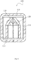
- Fig. 4 is a cross-sectional view of the conductive terminal of Fig. 1 taken along a plane A-A of Fig. 3
- Fig. 5 is a perspective view of the conductive terminal of Fig. 1 .
- a conductive terminal 100 adapted to electrically connect a wire 200 to a circuit board 300.
- the conductive terminal 100 comprises a support frame 110, a pair of first clamping arms 120 and a pair of second clamping arms 130.
- the support frame 110 defines a receiving space therein where the pair of first clamping arms 120 and the pair of second clamping arms 130 are arranged.
- a pair of first clamping portions 121 are formed at ends of the pair of first clamping arms 120 and adapted to selectively clamp a conductor 210 of the wire 200 inserted in a first insertion direction, so that the wire 200 is electrically connected with the conductive terminal 100.
- a pair of second clamping portions 131 are formed at ends of the pair of second clamping arms 130 and adapted to selectively clamp the conductor 210 of the wire 200 inserted in a second insertion direction different from the first insertion direction, so that the wire is electrically connected with the conductive terminal.
- the support frame 110 comprises: a bottom wall 111; two side walls 112; a first end wall 113 at a first end (a right end in Figs. 1 and 2 ) of the support frame; a second end wall 117 at a second end (a left end in Figs. 1 and 2 ) of the support frame and opposite to the first end wall 113; and a top wall 116.
- the side wall 112 is perpendicular to the bottom wall 111.
- the two side walls 112 are formed by bending perpendicularly downward from both sides of the top wall 116.
- the bottom wall 111 is formed by bending perpendicularly from a lower side of at least one of the two side walls toward the other opposite to the side wall where the lower side is located.
- the first end wall 113 is formed by perpendicularly bending from one end of the top wall 116 toward the bottom wall.
- the second end wall 117 is formed by bending perpendicularly from the other end of the top wall 116 toward the bottom wall.
- the second end wall 117 is formed by bending from one end of the two side walls 112 towards each other in a direction perpendicular to a plane where the side walls 112 are located.
- the support frame 110, the first clamping arm 120, and the second clamping arm 130 are integrally formed from a single piece of sheet metal.
- the conductive terminal 100 is formed from a single metal sheet such as a copper sheet by shearing, stamping, and bending processes.
- the first insertion direction is perpendicular to the second insertion direction (as shown in Figs. 6-9 ). Specifically, the first insertion direction is parallel to the plane where the bottom wall 111 is located, and the second insertion direction is perpendicular to the plane where the bottom wall 111 is located. In an embodiment, the first insertion direction is a horizontal direction and the second insertion direction is a vertical direction. In a further embodiment, the first insertion direction and the second insertion direction may be non-perpendicular, for example, the first insertion direction is a direction intersecting the plane where the bottom wall 111 is located at an angle other than 90 degrees.
- the support frame 110 further includes a pair of cantilevers 1121 that are formed by bending inwardly from the first ends of the two side walls 112.
- the pair of first clamping arms 120 extend downstream in the first insertion direction and obliquely toward each other respectively from free ends of the cantilevers away from the first ends of the side wall 112.
- the pair of second clamping arms 130 extend downstream in the second insertion direction and obliquely toward each other respectively from sides of the cantilevers away from the bottom wall 111.
- the pair of first clamping arms 120 extend obliquely toward each other respectively from the free ends of the cantilevers 1121 away from the first end of the side wall 112 toward second ends of the side walls 112 opposite to the first end; and the pair of second clamping arms 130 extend obliquely upwardly toward each other respectively from sides of the cantilevers 1121 away from the bottom wall.
- the support frame 110 includes two pairs of cantilevers 1121 that are respectively formed by bending inwardly from the first ends of the two side walls.
- the pair of first clamping arms 120 extend downstream in the first insertion direction and obliquely toward each other respectively from the free ends of one of one pair of the cantilevers away from the first end of the side wall; and the pair of second clamping arms extend downstream in the second insertion direction obliquely toward each other respectively from the sides of one of the other pair of the cantilevers away from the bottom wall.
- the first end wall 113 is located at the first end of the support frame, and is provided with a first insertion hole 114 adapted to allow the conductor 210 of the wire 200 to be inserted therethrough in the first insertion direction.
- the bottom wall 111 is provided with a second insertion hole 115 adapted to allow the conductor 210 of the wire 200 to be inserted therethrough in the second insertion direction.
- the second insertion hole 115 is aligned with the second clamping arm 130.
- the second insertion hole 115 may be not aligned with the second clamping arm 130.
- the top wall 116 is provided with a through hole 118 to allow the conductor 210 of the wire 200 inserted in the second insertion direction to extend out of the conductive terminal 100.
- the second insertion hole 115 is aligned with the second clamping arm 130 and the through hole 118.
- the second insertion hole 115 may be not aligned with the second clamping arm 130 and the through hole 118.
- the top wall 116 may not be provided with the through hole, in this case, the conductor of the wire inserted in the second insertion direction is received in the receiving space of the support frame. In this way, the top wall may block a further movement in the second insertion direction of the conductor that has been inserted into the conductive terminal in the second insertion direction.
- the second end wall 117 may block a further movement in the first insertion direction of the conductor 210 that has been inserted into the conductive terminal in the first insertion direction.
- the second end wall may be provided with a through hole, so that the conductor of the wire inserted in the first insertion direction may extend out of the through hole.
- the first clamping portions 121 are provided with wire-penetrating portions 1211
- the second clamping portions 131 are provided with wire-penetrating portions 1311.
- the wire-penetrating portions are adapted to clamp and penetrate an insulation layer of the wire 200 to be electrically connected with the conductor 210, and prevent the conductor from being pulled from the first insertion hole 114 or the second insertion hole 115. With this arrangement, the conductor 210 of the wire 200 may be reliably held in the conductive terminal 100.
- the first clamping arm 120 and/or the second clamping arm 130 further comprise a release portion.
- the release portion is adapted to move in a direction away from each other by an external force to spread the clamping portions 121 or 131, thereby releasing the wire.
- the release portion of the first clamping arm 120 includes an arc portion formed on a side of at least one of the pair of the first clamping arms 120 away from the bottom wall 111.
- a release portion 122 of the first clamping arm 120 includes two arc portions 1221 respectively formed on the sides of the pair of the first clamping arms 120.
- the arc portions 1221 are deflected outwardly away from each other.
- the release portion of the second clamping arm 130 includes an arc portion formed on at least one of the two ends of the second clamping portion 131. In a further embodiment, the release portion of the second clamping arm 130 includes two arc portions respectively formed on the two ends of the second clamping portion 131. The arc portions are deflected outwardly away from each other.
- the top wall 116 is provided with a release hole, and an external release tool is adapted to drive the release portion through the release hole and cause the release portion to move in directions away from each other to release the wire.
- the top wall 116 is provided with a release hole 119 that is aligned with the release portion 121 of the first clamp arm 120.
- the release hole 119 may be not aligned with the release portion 121 of the first clamp arm 120.
- the top wall is further provided with a release hole that is aligned with the release portion of the second clamp arm 130.
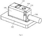
- Fig. 6 is a schematic view of the connector assembly of Fig. 1 , wherein a conductor of a wire is inserted into the connector assembly in a first insertion direction
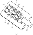
- Fig. 7 is a schematic view of connector assembly of Fig. 6 , wherein, for the sake of observation, the top wall of the conductive terminal is not shown
- Fig. 8 is a schematic view of the connector assembly of Fig. 1 , wherein the conductor of the wire is inserted into the connector assembly in a second insertion direction
- Fig. 9 is a cross-sectional perspective view of the connector assembly of Fig. 8 taken along the plane A-A of Fig. 3 .
- a connector assembly 1 comprising the conductive terminal 100 and the circuit board 300, the conductive terminal 100 being electrically connected to the circuit board 300.
- the conductive terminal is the one of any of the embodiments.
- the circuit board 300 is provided with a through hole.
- the second clamping arm 130 of the conductive terminal 100 is adapted to selectively clamp the conductor 210 of the wire 200 inserted through the through hole of the circuit board 300 from the second insertion direction.
- the bottom wall 11 of the support frame 110 is fitted with a surface of the circuit board 300, the second insertion hole 115 of the conductive terminal 100 is aligned with the through hole of the circuit board 300, and then the conductive terminal 100 is soldered to solder pads of the circuit board 300 by surface mount technology (SMT). Therefore, a reliable electrical connection between the conductive terminals 100 and the circuit board 300 is achieved.
- SMT surface mount technology
- the conductor 210 of the wire is inserted into the conductive terminal 100 from the insertion hole 114 and clamped by the pair of first clamping arms 120. And, the wire-penetrating portion 1211 of the first clamping portion 121 of the first clamping arm 120 penetrates an insulation layer of the wire 200, such that the wire 200 is reliably held and electrically connected with the conductive terminal.
- the external release tool passes through the release hole 119 to drive the release portion 122, so that the release portion 122 moves towards the directions away from each other, the clamp portion 121 clamping the wire 200 is spread, and thus the wire 200 is released.
- an end of the external release tool is a plate member.
- the external release tool may comprise a screwdriver.
- the conductor 210 of the wire passes through the through hole of the circuit board, and is inserted into the conductive terminal 100 from the second insertion hole 115 in the second insertion direction and clamped by the pair of second clamping arms 130.
- the wire-penetrating portion 1311 of the second clamping portion 131 of the second clamping arm 130 penetrates an insulation layer of the wire 200, such that the wire 200 is reliably held and electrically connected with the conductive terminal.
- the conductive terminal of the present disclosure allows the wire to be inserted selectively from the first or second insertion direction, so as to meet the requirement of inserting the wire from two directions.
Landscapes
- Engineering & Computer Science (AREA)
- Microelectronics & Electronic Packaging (AREA)
- Coupling Device And Connection With Printed Circuit (AREA)
- Multi-Conductor Connections (AREA)
Abstract
Description
- This application claims the benefit of Chinese Patent Application No.
201811258797.X filed on October 26, 2018 - Embodiments of the present disclosure relate to a conductive terminal and a connector assembly comprising the same, in particular to a wire-to-board conductive terminal without a housing and a connector assembly comprising the same, and in more particular to a conductive terminal adapted to be electrically connected with a wire selectively inserted from a first or second direction and a connector assembly comprising the same.
- In a relevant art, a wire is electrically connected to an electrical board generally by an electrical connector. When being electrically connected to the electrical board, generally, a conductive terminal of the electrical connector is fixed in an insulating housing in advance, and then electrically connected to and fixed to the electrical board. However, such a connecting means is not only costly, but also causes the insulating housing occupying a larger space of the electrical board.
- In order to overcome the deficiency, there is proposed, in the relevant art, an improved conductive terminal which may electrically connect the wire to the electrical board without housing covered. Nevertheless, an insertion direction of the wire is unchanged for the conductive terminal. For example, the conductive terminal only allows the wire to be inserted horizontally or vertically. With an increase in demand of customer, it is desired for a conductive terminal to allow the wire to be inserted therein both horizontally and vertically.
- In addition, a current conductive terminal without housing has low locating and holding performance for the wire inserted therein, and thus the wire is easily disconnected therefrom.
- Therefore, there is a need to a conductive terminal and connector assembly comprising the same that may solve the above problems.
- An objective of the present disclosure is to solve at least one aspect of the above mentioned problems and disadvantages occurred in the prior art.
- According to an exemplary embodiment of an aspect of the present disclosure, there is provided a conductive terminal adapted to electrically connect a wire to a circuit board, comprising: a support frame adapted to define a receiving space therein; a pair of first clamping arms arranged in the receiving space, first clamping portions being formed at ends of the first clamping arms and adapted to selectively clamp a conductor of the wire inserted in a first insertion direction, so that the wire is electrically connected with the conductive terminal; and a pair of second clamping arms arranged in the receiving space, second clamping portions being formed at ends of the second clamping arms and adapted to selectively clamp the conductor of the wire inserted in a second insertion direction different from the first insertion direction, so that the wire is electrically connected with the conductive terminal.
- According to an exemplary embodiment of the present disclosure, the first insertion direction is perpendicular to the second insertion direction.
- According to an exemplary embodiment of the present disclosure, the support frame comprises a bottom wall and two side walls perpendicular to the bottom wall, the first insertion direction being parallel to a plane where the bottom wall is located, and the second insertion direction being perpendicular to the plane where the bottom wall is located.
- According to an exemplary embodiment of the present disclosure, the support frame, the first clamping arm, and the second clamping arm are integrally formed from a single piece of sheet metal.
- According to an exemplary embodiment of the present disclosure, the support frame further comprises a pair of cantilevers that are formed by bending inwardly from first ends of the two side walls, the pair of first clamping arms extending downstream in the first insertion direction and obliquely toward each other respectively from free ends of the cantilevers away from the first ends.
- According to an exemplary embodiment of the present disclosure, the pair of second clamping arms extend downstream in the second insertion direction and obliquely toward each other respectively from sides of the cantilevers away from the bottom wall.
- According to an exemplary embodiment of the present disclosure, the support frame further comprises a first end wall located at an upstream side in the first insertion direction and provided with a first insertion hole adapted to allow the conductor of the wire to be inserted therethrough in the first insertion direction.
- According to an exemplary embodiment of the present disclosure, the bottom wall comprises a second insertion hole adapted to allow the conductor of the wire to be inserted therethrough in the second insertion direction.
- According to an exemplary embodiment of the present disclosure, the support frame further a top wall, the two side walls being formed by bending perpendicularly downward from both sides of the top wall, the bottom wall being formed by bending perpendicularly from a lower side of at least one of the two side walls toward the other opposite to the side wall where the lower side is located, and the first end wall being formed by bending perpendicularly from one end of the top wall toward the bottom wall.
- According to an exemplary embodiment of the present disclosure, the support frame further comprises a second end wall opposite to the first end wall and adapted to block the conductor of the wire inserted in the first insertion direction.
- According to an exemplary embodiment of the present disclosure, the top wall is provided with a through hole to allow the conductor of the wire inserted in the second insertion direction to extend out of the conductive terminal.
- According to an exemplary embodiment of the present disclosure, the first clamping arm and/or the second clamping arm further comprise a pair of release portions adapted to move in directions away from each other by an external force to spread the clamping portion.
- According to an exemplary embodiment of the present disclosure, the top wall is provided with a release hole communicated with the release portion.
- According to an exemplary embodiment of the present disclosure, the first and second clamping portions are provided with wire-penetrating portions adapted to clamp and penetrate an insulation layer of the wire to be electrically connected with the conductor.
- According to an exemplary embodiment of another aspect of the present disclosure, there is provided a connector assembly, comprising: the conductive terminal according to any one of above embodiments; and a circuit board to which the conductive terminal is electrically connected, the circuit board being provided with a through hole, the second clamping arms of the conductive terminal being adapted to selectively clamp the conductor of the wire inserted through the through hole of the circuit board in the second insertion direction.
- Other objectives and advantages of the present disclosure will become apparent from the following description of the present disclosure when taken in conjunction with the accompanying drawings, and may give a comprehensive understanding of the present disclosure.
- The above and other features of the present disclosure will become more apparent by describing in detail exemplary embodiments thereof with reference to the accompanying drawings, in which:
-
Fig. 1 is a perspective view of a connector assembly comprising a conductive terminal and an electrical board according to an exemplary embodiment of the present disclosure; -
Fig. 2 is a perspective view of the conductive terminal ofFig. 1 , wherein, for the sake of observation, a top wall of the conductive terminal is not shown; -
Fig. 3 is a top view of the conductive terminal ofFig. 1 , wherein, for the sake of observation, a top wall of the conductive terminal is not shown; -
Fig. 4 is a cross-sectional view of the conductive terminal ofFig. 1 taken along a plane A-A ofFig. 3 ; -
Fig. 5 is a perspective view of the conductive terminal ofFig. 1 ; -
Fig. 6 is a schematic view of the connector assembly ofFig. 1 , wherein a conductor of a wire is inserted into the connector assembly in a first insertion direction; -
Fig. 7 is a schematic view of the connector assembly ofFig. 6 , wherein, for the sake of observation, the top wall of the conductive terminal is not shown; -
Fig. 8 is a schematic view of the connector assembly ofFig. 1 , wherein the conductor of the wire is inserted into the connector assembly in a second insertion direction; and -
Fig. 9 is a cross-sectional perspective view of the connector assembly ofFig. 8 taken along the plane A-A ofFig. 3 . - The technical solution of the present disclosure will be described hereinafter in further detail with reference to the following embodiments, taken in conjunction with the accompanying drawings. In the specification, the same or similar reference numerals indicate the same or similar parts. The description of the embodiments of the present disclosure hereinafter with reference to the accompanying drawings is intended to explain the general inventive concept of the present disclosure, and should not be constructed as a limitation to the present disclosure.
- In addition, in the following detailed description, for the sake of explanation, numerous specific details are set forth in order to provide a thorough understanding of the disclosed embodiments. It will be apparent, however, one or more embodiments may also be practiced without these specific details. In other instances, well-known structures and devices are illustrated schematically in order to simplify the drawing.
- According to a general technical concept of the present disclosure, there is provided a conductive terminal adapted to electrically connect a wire to a circuit board, comprising: a support frame adapted to define a receiving space therein; a pair of first clamping arms arranged in the receiving space, first clamping portions being formed at ends of the first clamping arms and adapted to selectively clamp a conductor of the wire inserted in a first insertion direction, so that the wire is electrically connected with the conductive terminal; and a pair of second clamping arms arranged in the receiving space, second clamping portions being formed at ends of the second clamping arms and adapted to selectively clamp the conductor of the wire inserted in a second insertion direction different from the first insertion direction, so that the wire is electrically connected with the conductive terminal.
-
Fig. 1 is a perspective view of a connector assembly comprising a conductive terminal and an electrical board according to an exemplary embodiment of the present disclosure;Fig. 2 is a perspective view of the conductive terminal ofFig. 1 , wherein, for the sake of observation, a top wall of the conductive terminal is not shown;Fig. 3 is a top view of the conductive terminal ofFig. 1 , wherein, for the sake of observation, a top wall of the conductive terminal is not shown;Fig. 4 is a cross-sectional view of the conductive terminal ofFig. 1 taken along a plane A-A ofFig. 3 ; andFig. 5 is a perspective view of the conductive terminal ofFig. 1 . - As shown in
Figs. 1-5 , in an exemplary embodiment of the present disclosure, there is provided aconductive terminal 100 adapted to electrically connect awire 200 to acircuit board 300. Theconductive terminal 100 comprises asupport frame 110, a pair of first clampingarms 120 and a pair of second clampingarms 130. Thesupport frame 110 defines a receiving space therein where the pair of first clampingarms 120 and the pair of second clampingarms 130 are arranged. A pair offirst clamping portions 121 are formed at ends of the pair of first clampingarms 120 and adapted to selectively clamp aconductor 210 of thewire 200 inserted in a first insertion direction, so that thewire 200 is electrically connected with theconductive terminal 100. A pair ofsecond clamping portions 131 are formed at ends of the pair of second clampingarms 130 and adapted to selectively clamp theconductor 210 of thewire 200 inserted in a second insertion direction different from the first insertion direction, so that the wire is electrically connected with the conductive terminal. - As shown in
Figs. 1-5 , in an exemplary embodiment of the present disclosure, thesupport frame 110 comprises: abottom wall 111; twoside walls 112; afirst end wall 113 at a first end (a right end inFigs. 1 and2 ) of the support frame; asecond end wall 117 at a second end (a left end inFigs. 1 and2 ) of the support frame and opposite to thefirst end wall 113; and atop wall 116. In an embodiment, theside wall 112 is perpendicular to thebottom wall 111. In an illustrated embodiment, the twoside walls 112 are formed by bending perpendicularly downward from both sides of thetop wall 116. Thebottom wall 111 is formed by bending perpendicularly from a lower side of at least one of the two side walls toward the other opposite to the side wall where the lower side is located. Thefirst end wall 113 is formed by perpendicularly bending from one end of thetop wall 116 toward the bottom wall. In an embodiment, thesecond end wall 117 is formed by bending perpendicularly from the other end of thetop wall 116 toward the bottom wall. In an alternative embodiment, thesecond end wall 117 is formed by bending from one end of the twoside walls 112 towards each other in a direction perpendicular to a plane where theside walls 112 are located. - In an embodiment, the
support frame 110, thefirst clamping arm 120, and thesecond clamping arm 130 are integrally formed from a single piece of sheet metal. Theconductive terminal 100 is formed from a single metal sheet such as a copper sheet by shearing, stamping, and bending processes. - In the illustrated embodiment, the first insertion direction is perpendicular to the second insertion direction (as shown in
Figs. 6-9 ). Specifically, the first insertion direction is parallel to the plane where thebottom wall 111 is located, and the second insertion direction is perpendicular to the plane where thebottom wall 111 is located. In an embodiment, the first insertion direction is a horizontal direction and the second insertion direction is a vertical direction. In a further embodiment, the first insertion direction and the second insertion direction may be non-perpendicular, for example, the first insertion direction is a direction intersecting the plane where thebottom wall 111 is located at an angle other than 90 degrees. - As shown in
Figs. 1-5 , in an exemplary embodiment of the present disclosure, thesupport frame 110 further includes a pair ofcantilevers 1121 that are formed by bending inwardly from the first ends of the twoside walls 112. In an embodiment, the pair of first clampingarms 120 extend downstream in the first insertion direction and obliquely toward each other respectively from free ends of the cantilevers away from the first ends of theside wall 112. - In an embodiment, the pair of second clamping
arms 130 extend downstream in the second insertion direction and obliquely toward each other respectively from sides of the cantilevers away from thebottom wall 111. In the illustrated embodiment, the pair of first clampingarms 120 extend obliquely toward each other respectively from the free ends of thecantilevers 1121 away from the first end of theside wall 112 toward second ends of theside walls 112 opposite to the first end; and the pair of second clampingarms 130 extend obliquely upwardly toward each other respectively from sides of thecantilevers 1121 away from the bottom wall. - In an alternative embodiment, the
support frame 110 includes two pairs ofcantilevers 1121 that are respectively formed by bending inwardly from the first ends of the two side walls. In this case, the pair of first clampingarms 120 extend downstream in the first insertion direction and obliquely toward each other respectively from the free ends of one of one pair of the cantilevers away from the first end of the side wall; and the pair of second clamping arms extend downstream in the second insertion direction obliquely toward each other respectively from the sides of one of the other pair of the cantilevers away from the bottom wall. - As shown in
Figs. 1-5 , in an exemplary embodiment of the present disclosure, thefirst end wall 113 is located at the first end of the support frame, and is provided with afirst insertion hole 114 adapted to allow theconductor 210 of thewire 200 to be inserted therethrough in the first insertion direction. - As shown in
Figs. 1-5 , in an exemplary embodiment of the present disclosure, thebottom wall 111 is provided with asecond insertion hole 115 adapted to allow theconductor 210 of thewire 200 to be inserted therethrough in the second insertion direction. In the illustrated embodiment, thesecond insertion hole 115 is aligned with thesecond clamping arm 130. In an alternative embodiment, thesecond insertion hole 115 may be not aligned with thesecond clamping arm 130. - As shown in
Figs. 1-5 , in an exemplary embodiment of the present disclosure, thetop wall 116 is provided with a throughhole 118 to allow theconductor 210 of thewire 200 inserted in the second insertion direction to extend out of theconductive terminal 100. In the illustrated embodiment, thesecond insertion hole 115 is aligned with thesecond clamping arm 130 and the throughhole 118. In an alternative embodiment, thesecond insertion hole 115 may be not aligned with thesecond clamping arm 130 and the throughhole 118. - In an embodiment, the
top wall 116 may not be provided with the through hole, in this case, the conductor of the wire inserted in the second insertion direction is received in the receiving space of the support frame. In this way, the top wall may block a further movement in the second insertion direction of the conductor that has been inserted into the conductive terminal in the second insertion direction. - As shown in
Figs. 1-5 , in an exemplary embodiment of the present disclosure, thesecond end wall 117 may block a further movement in the first insertion direction of theconductor 210 that has been inserted into the conductive terminal in the first insertion direction. In an embodiment, the second end wall may be provided with a through hole, so that the conductor of the wire inserted in the first insertion direction may extend out of the through hole. - As shown in
Figs. 1-5 , in an exemplary embodiment of the present disclosure, thefirst clamping portions 121 are provided with wire-penetratingportions 1211, and thesecond clamping portions 131 are provided with wire-penetratingportions 1311. The wire-penetrating portions are adapted to clamp and penetrate an insulation layer of thewire 200 to be electrically connected with theconductor 210, and prevent the conductor from being pulled from thefirst insertion hole 114 or thesecond insertion hole 115. With this arrangement, theconductor 210 of thewire 200 may be reliably held in theconductive terminal 100. - As shown in
Figs. 1-5 , in an exemplary embodiment of the present disclosure, thefirst clamping arm 120 and/or thesecond clamping arm 130 further comprise a release portion. The release portion is adapted to move in a direction away from each other by an external force to spread the clampingportions first clamping arm 120 includes an arc portion formed on a side of at least one of the pair of the first clampingarms 120 away from thebottom wall 111. - In the illustrated embodiment, a
release portion 122 of thefirst clamping arm 120 includes twoarc portions 1221 respectively formed on the sides of the pair of the first clampingarms 120. Thearc portions 1221 are deflected outwardly away from each other. - In a further embodiment, the release portion of the
second clamping arm 130 includes an arc portion formed on at least one of the two ends of thesecond clamping portion 131. In a further embodiment, the release portion of thesecond clamping arm 130 includes two arc portions respectively formed on the two ends of thesecond clamping portion 131. The arc portions are deflected outwardly away from each other. - As shown in
Figs. 1-5 , in an exemplary embodiment of the present invention, thetop wall 116 is provided with a release hole, and an external release tool is adapted to drive the release portion through the release hole and cause the release portion to move in directions away from each other to release the wire. In the illustrated embodiment, thetop wall 116 is provided with arelease hole 119 that is aligned with therelease portion 121 of thefirst clamp arm 120. In an alternative embodiment, therelease hole 119 may be not aligned with therelease portion 121 of thefirst clamp arm 120. In a further embodiment, the top wall is further provided with a release hole that is aligned with the release portion of thesecond clamp arm 130. -
Fig. 6 is a schematic view of the connector assembly ofFig. 1 , wherein a conductor of a wire is inserted into the connector assembly in a first insertion direction;Fig. 7 is a schematic view of connector assembly ofFig. 6 , wherein, for the sake of observation, the top wall of the conductive terminal is not shown;Fig. 8 is a schematic view of the connector assembly ofFig. 1 , wherein the conductor of the wire is inserted into the connector assembly in a second insertion direction; andFig. 9 is a cross-sectional perspective view of the connector assembly ofFig. 8 taken along the plane A-A ofFig. 3 . - As shown in
Figs. 1 and6-9 , in an exemplary embodiment of the present disclosure, there is provided a connector assembly 1 comprising theconductive terminal 100 and thecircuit board 300, theconductive terminal 100 being electrically connected to thecircuit board 300. The conductive terminal is the one of any of the embodiments. Thecircuit board 300 is provided with a through hole. Thesecond clamping arm 130 of theconductive terminal 100 is adapted to selectively clamp theconductor 210 of thewire 200 inserted through the through hole of thecircuit board 300 from the second insertion direction. - In an exemplary embodiment, with suction nozzles of the vacuum adsorption apparatus sucking the
top wall 116 of thesupport frame 110 of theconductive terminal 100, the bottom wall 11 of thesupport frame 110 is fitted with a surface of thecircuit board 300, thesecond insertion hole 115 of theconductive terminal 100 is aligned with the through hole of thecircuit board 300, and then theconductive terminal 100 is soldered to solder pads of thecircuit board 300 by surface mount technology (SMT). Therefore, a reliable electrical connection between theconductive terminals 100 and thecircuit board 300 is achieved. - As shown in
Figs. 6 and7 , in an exemplary embodiment, during inserting thewire 200 into theconductive terminal 100 in the first insertion direction (in a horizontal direction in the illustrated embodiment), theconductor 210 of the wire is inserted into the conductive terminal 100 from theinsertion hole 114 and clamped by the pair of first clampingarms 120. And, the wire-penetratingportion 1211 of thefirst clamping portion 121 of thefirst clamping arm 120 penetrates an insulation layer of thewire 200, such that thewire 200 is reliably held and electrically connected with the conductive terminal. In an embodiment, during releasing thewire 200 from the conductive terminal, the external release tool passes through therelease hole 119 to drive therelease portion 122, so that therelease portion 122 moves towards the directions away from each other, theclamp portion 121 clamping thewire 200 is spread, and thus thewire 200 is released. In an embodiment, an end of the external release tool is a plate member. In an embodiment, the external release tool may comprise a screwdriver. - As shown in
Figs. 8 and9 , in an exemplary embodiment, during inserting thewire 200 into theconductive terminal 100 in the second insertion direction (in a vertical direction in the illustrated embodiment), theconductor 210 of the wire passes through the through hole of the circuit board, and is inserted into the conductive terminal 100 from thesecond insertion hole 115 in the second insertion direction and clamped by the pair of second clampingarms 130. And, the wire-penetratingportion 1311 of thesecond clamping portion 131 of thesecond clamping arm 130 penetrates an insulation layer of thewire 200, such that thewire 200 is reliably held and electrically connected with the conductive terminal. - In such a way, the conductive terminal of the present disclosure allows the wire to be inserted selectively from the first or second insertion direction, so as to meet the requirement of inserting the wire from two directions.
- Although the present disclosure has been described with reference to the attached drawings, the embodiments disclosed in the drawings are intended to illustrate the preferred embodiments of the present disclosure, but should not be constructed as a limitation to the present disclosure.
- Although several exemplary embodiments have been shown and described, it would be appreciated by those skilled in the art that various changes or modifications may be made in these embodiments without departing from the principles and spirit of the disclosure, the scope of which is not defined by the exemplary embodiments of the present disclosure, but defined in the claims and their equivalents.
- It should be noted that term "comprising" or "including" should be understood as not excluding other elements or steps, and term "a" or "an" should be understood as not excluding plural elements or steps. Further, any reference numerals in claims should not be understood as a limitation to the present disclosure.
Claims (15)
- A conductive terminal adapted to electrically connect a wire to a circuit board, comprising:a support frame adapted to define a receiving space therein;a pair of first clamping arms arranged in the receiving space, first clamping portions being formed at ends of the first clamping arms and adapted to selectively clamp a conductor of the wire inserted in a first insertion direction, so that the wire is electrically connected with the conductive terminal; anda pair of second clamping arms arranged in the receiving space, second clamping portions being formed at ends of the second clamping arms and adapted to selectively clamp the conductor of the wire inserted in a second insertion direction different from the first insertion direction, so that the wire is electrically connected with the conductive terminal.
- The conductive terminal according to claim 1, wherein, the first insertion direction is perpendicular to the second insertion direction.
- The conductive terminal according to claim 2, wherein, the support frame comprises a bottom wall and two side walls perpendicular to the bottom wall, the first insertion direction being parallel to a plane where the bottom wall is located, and the second insertion direction being perpendicular to the plane where the bottom wall is located.
- The conductive terminal according to claim 1, wherein, the support frame, the first clamping arm and the second clamping arm are integrally formed from a single piece of sheet metal.
- The conductive terminal according to claim 3, wherein, the support frame further comprises a pair of cantilevers that are formed by bending inwardly from first ends of the two side walls, the pair of first clamping arms extending downstream in the first insertion direction and obliquely toward each other from free ends of the cantilevers away from the first ends.
- The conductive terminal according to claim 5, wherein, the pair of second clamping arms extend downstream in the second insertion direction and obliquely toward each other from sides of the cantilevers away from the bottom wall.
- The conductive terminal according to claim 3, wherein, the support frame further comprises a first end wall located at an upstream side in the first insertion direction and provided with a first insertion hole adapted to allow the conductor of the wire to be inserted therethrough in the first insertion direction.
- The conductive terminal according to claim 3, wherein, the bottom wall comprises a second insertion hole adapted to allow the conductor of the wire to be inserted therethrough in the second insertion direction.
- The conductive terminal according to claim 7, wherein, the support frame further a top wall, the two side walls being formed by bending perpendicularly downward from both sides of the top wall, the bottom wall being formed by bending perpendicularly from a lower side of at least one of the two side walls toward the other opposite to the side wall where the lower side is located, and the first end wall being formed by bending perpendicularly from one end of the top wall toward the bottom wall.
- The conductive terminal according to claim 7, wherein, the support frame further comprises a second end wall opposite to the first end wall and adapted to block the conductor of the wire inserted in the first insertion direction.
- The conductive terminal according to claim 9, wherein, the top wall is provided with a through hole to allow the conductor of the wire inserted in the second insertion direction to extend out of the conductive terminal.
- The conductive terminal according to claim 9, wherein, the first clamping arm and/or the second clamping arm further comprise a pair of release portions adapted to move in directions away from each other by an external force to spread the clamping portions.
- The conductive terminal according to claim 12, wherein, the top wall is provided with a release hole communicated with the release portion.
- The conductive terminal according to claim 1, wherein, the first and second clamping portions are provided with wire-penetrating portions adapted to clamp and penetrate an insulation layer of the wire to be electrically connected with the conductor.
- A connector assembly, comprising:the conductive terminal according to claim 1; anda circuit board to which the conductive terminal is electrically connected, the circuit board being provided with a through hole, the second clamping arms of the conductive terminal being adapted to selectively clamp the conductor of the wire inserted through the through hole of the circuit board in the second insertion direction.
Priority Applications (1)
| Application Number | Priority Date | Filing Date | Title |
|---|---|---|---|
| PL19204553T PL3644446T3 (en) | 2018-10-26 | 2019-10-22 | CONDUCTIVE CLAMP AND CONNECTION UNIT |
Applications Claiming Priority (1)
| Application Number | Priority Date | Filing Date | Title |
|---|---|---|---|
| CN201811258797.XA CN111106471B (en) | 2018-10-26 | 2018-10-26 | Conductive terminal and connector assembly |
Publications (2)
| Publication Number | Publication Date |
|---|---|
| EP3644446A1 true EP3644446A1 (en) | 2020-04-29 |
| EP3644446B1 EP3644446B1 (en) | 2021-08-04 |
Family
ID=68296381
Family Applications (1)
| Application Number | Title | Priority Date | Filing Date |
|---|---|---|---|
| EP19204553.2A Active EP3644446B1 (en) | 2018-10-26 | 2019-10-22 | Conductive terminal and connector assembly |
Country Status (4)
| Country | Link |
|---|---|
| US (1) | US10833429B2 (en) |
| EP (1) | EP3644446B1 (en) |
| CN (1) | CN111106471B (en) |
| PL (1) | PL3644446T3 (en) |
Families Citing this family (3)
| Publication number | Priority date | Publication date | Assignee | Title |
|---|---|---|---|---|
| CN114334558B (en) * | 2020-09-30 | 2024-06-18 | 上海良信电器股份有限公司 | breaker |
| CN114007027B (en) * | 2021-10-12 | 2023-12-05 | 惠州视维新技术有限公司 | Television with automatic signal wire insertion |
| CN115173124A (en) * | 2022-07-27 | 2022-10-11 | 东莞市林积为实业投资有限公司 | Floating radio frequency connector |
Citations (2)
| Publication number | Priority date | Publication date | Assignee | Title |
|---|---|---|---|---|
| US20140120783A1 (en) * | 2012-11-01 | 2014-05-01 | Avx Corporation | Single element wire to board connector |
| EP3179566A1 (en) * | 2015-12-11 | 2017-06-14 | Continental Automotive GmbH | Cable harness connection assembly |
Family Cites Families (23)
| Publication number | Priority date | Publication date | Assignee | Title |
|---|---|---|---|---|
| FR2708385B1 (en) * | 1993-07-28 | 1995-09-01 | Entrelec Sa | Electric terminal block. |
| TW472962U (en) * | 2000-12-21 | 2002-01-11 | Hon Hai Prec Ind Co Ltd | Connector terminal with no insertion force |
| JP2003332014A (en) * | 2002-05-16 | 2003-11-21 | Mitsumi Electric Co Ltd | AC-DC power adapter |
| US7513793B2 (en) * | 2006-12-22 | 2009-04-07 | Tyco Electronics Corporation | Surface mount poke in connector |
| US7448873B2 (en) * | 2007-01-08 | 2008-11-11 | Tyco Electronics Corporation | Connector assembly for end mounting panel members |
| DE102010024155B4 (en) * | 2009-06-17 | 2015-06-03 | Lear Corp. | Automobile fuse for connection to a power distribution box and combination of a power distribution box with such automotive fuse |
| DE102010014143B4 (en) * | 2010-04-07 | 2016-07-07 | Wago Verwaltungsgesellschaft Mbh | Actuation device for an electrical connection terminal |
| CN103367955A (en) * | 2012-04-17 | 2013-10-23 | 苏州方林科技股份有限公司 | Battery connector terminal and battery assembly using battery connector terminal |
| CN102709729B (en) * | 2012-06-12 | 2015-12-09 | 昆山科信成电子有限公司 | Splicing ear, coaxial electric coupler and wiring construction thereof |
| USD745459S1 (en) * | 2013-06-17 | 2015-12-15 | Wago Verwaltungsgesellschaft Mbh | Electrical plug-in connector |
| GB2516555B (en) * | 2013-06-26 | 2015-07-29 | Avx Corp | Single element wire to board connector |
| JP6123690B2 (en) * | 2014-01-31 | 2017-05-10 | 株式会社オートネットワーク技術研究所 | Earth terminal unit |
| CN204966753U (en) * | 2015-07-31 | 2016-01-13 | 泰科电子(上海)有限公司 | Connector and connector assembly |
| CN205039288U (en) * | 2015-08-27 | 2016-02-17 | 泰科电子(上海)有限公司 | Connector |
| CN205051062U (en) * | 2015-09-14 | 2016-02-24 | 泰科电子(上海)有限公司 | Connector and connector assembly |
| TWM517439U (en) * | 2015-10-16 | 2016-02-11 | 唐虞企業股份有限公司 | Single component wire-to-board connection terminal |
| DE102015121638B4 (en) * | 2015-12-11 | 2017-10-05 | Wago Verwaltungsgesellschaft Mbh | Conductor terminal and set of conductor terminal and operating tool |
| TWI575826B (en) * | 2016-01-18 | 2017-03-21 | Excel Cell Electronic Co Ltd | Terminal block |
| CN107516782B (en) * | 2016-06-16 | 2019-08-09 | 美国莫列斯有限公司 | Card edge attachment device |
| CN205960252U (en) * | 2016-07-12 | 2017-02-15 | 泰科电子(上海)有限公司 | Connecting device and connecting device assembly |
| CN207338716U (en) * | 2017-07-05 | 2018-05-08 | 泰科电子(上海)有限公司 | Connector |
| CN207977486U (en) * | 2018-01-23 | 2018-10-16 | 泰科电子(上海)有限公司 | Conducting terminal and connector assembly |
| CN209104428U (en) * | 2018-10-26 | 2019-07-12 | 泰科电子(上海)有限公司 | Conductive Terminal and Connector Assemblies |
-
2018
- 2018-10-26 CN CN201811258797.XA patent/CN111106471B/en active Active
-
2019
- 2019-10-22 PL PL19204553T patent/PL3644446T3/en unknown
- 2019-10-22 EP EP19204553.2A patent/EP3644446B1/en active Active
- 2019-10-28 US US16/665,600 patent/US10833429B2/en active Active
Patent Citations (2)
| Publication number | Priority date | Publication date | Assignee | Title |
|---|---|---|---|---|
| US20140120783A1 (en) * | 2012-11-01 | 2014-05-01 | Avx Corporation | Single element wire to board connector |
| EP3179566A1 (en) * | 2015-12-11 | 2017-06-14 | Continental Automotive GmbH | Cable harness connection assembly |
Also Published As
| Publication number | Publication date |
|---|---|
| CN111106471B (en) | 2025-08-19 |
| CN111106471A (en) | 2020-05-05 |
| PL3644446T3 (en) | 2022-02-14 |
| US10833429B2 (en) | 2020-11-10 |
| US20200136274A1 (en) | 2020-04-30 |
| EP3644446B1 (en) | 2021-08-04 |
Similar Documents
| Publication | Publication Date | Title |
|---|---|---|
| US10707598B2 (en) | Conductive terminal and connector assembly | |
| US9444159B2 (en) | Terminal for contacting an electrical conductor | |
| US9768527B2 (en) | Single element wire to board connector | |
| US7993156B2 (en) | Connecting terminal for printed circuit boards | |
| US11336040B2 (en) | Conductive terminal with clamping portion and connector assembly using the same | |
| CN107069262B (en) | Electrical connector | |
| EP3644446B1 (en) | Conductive terminal and connector assembly | |
| KR102316920B1 (en) | Printed circuit board with side access termination pads | |
| CN108879137B (en) | Terminal block | |
| US10985481B2 (en) | Electric contacting device | |
| CN111384614B (en) | Terminal assembly and power connector | |
| CN208045739U (en) | Conductive Terminals and Connector Assemblies | |
| US9673541B2 (en) | Spring clip and connection box | |
| EP3474382A1 (en) | Socket | |
| CN209104428U (en) | Conductive Terminal and Connector Assemblies | |
| WO2015068907A1 (en) | Connecter | |
| KR20160135882A (en) | Electric connector for a power cable | |
| CN218300341U (en) | Connector for cable | |
| JPH0963667A (en) | Coaxial cable connection structure | |
| CN210806040U (en) | Wire connector capable of being connected in parallel | |
| JP3033134B2 (en) | Printed circuit board connection device | |
| JP2009283338A (en) | Connector terminal, and connector provided with same connector terminal | |
| CN119209072A (en) | Connector | |
| JPH08190952A (en) | Orthogonal connection type relay terminal | |
| JP2017027740A (en) | connector |
Legal Events
| Date | Code | Title | Description |
|---|---|---|---|
| PUAI | Public reference made under article 153(3) epc to a published international application that has entered the european phase |
Free format text: ORIGINAL CODE: 0009012 |
|
| STAA | Information on the status of an ep patent application or granted ep patent |
Free format text: STATUS: THE APPLICATION HAS BEEN PUBLISHED |
|
| AK | Designated contracting states |
Kind code of ref document: A1 Designated state(s): AL AT BE BG CH CY CZ DE DK EE ES FI FR GB GR HR HU IE IS IT LI LT LU LV MC MK MT NL NO PL PT RO RS SE SI SK SM TR |
|
| AX | Request for extension of the european patent |
Extension state: BA ME |
|
| STAA | Information on the status of an ep patent application or granted ep patent |
Free format text: STATUS: REQUEST FOR EXAMINATION WAS MADE |
|
| 17P | Request for examination filed |
Effective date: 20200527 |
|
| RBV | Designated contracting states (corrected) |
Designated state(s): AL AT BE BG CH CY CZ DE DK EE ES FI FR GB GR HR HU IE IS IT LI LT LU LV MC MK MT NL NO PL PT RO RS SE SI SK SM TR |
|
| GRAP | Despatch of communication of intention to grant a patent |
Free format text: ORIGINAL CODE: EPIDOSNIGR1 |
|
| STAA | Information on the status of an ep patent application or granted ep patent |
Free format text: STATUS: GRANT OF PATENT IS INTENDED |
|
| INTG | Intention to grant announced |
Effective date: 20210401 |
|
| GRAS | Grant fee paid |
Free format text: ORIGINAL CODE: EPIDOSNIGR3 |
|
| GRAA | (expected) grant |
Free format text: ORIGINAL CODE: 0009210 |
|
| STAA | Information on the status of an ep patent application or granted ep patent |
Free format text: STATUS: THE PATENT HAS BEEN GRANTED |
|
| AK | Designated contracting states |
Kind code of ref document: B1 Designated state(s): AL AT BE BG CH CY CZ DE DK EE ES FI FR GB GR HR HU IE IS IT LI LT LU LV MC MK MT NL NO PL PT RO RS SE SI SK SM TR |
|
| REG | Reference to a national code |
Ref country code: GB Ref legal event code: FG4D |
|
| REG | Reference to a national code |
Ref country code: AT Ref legal event code: REF Ref document number: 1417958 Country of ref document: AT Kind code of ref document: T Effective date: 20210815 |
|
| REG | Reference to a national code |
Ref country code: CH Ref legal event code: EP |
|
| REG | Reference to a national code |
Ref country code: DE Ref legal event code: R096 Ref document number: 602019006622 Country of ref document: DE |
|
| REG | Reference to a national code |
Ref country code: IE Ref legal event code: FG4D |
|
| REG | Reference to a national code |
Ref country code: LT Ref legal event code: MG9D |
|
| REG | Reference to a national code |
Ref country code: NL Ref legal event code: MP Effective date: 20210804 |
|
| REG | Reference to a national code |
Ref country code: AT Ref legal event code: MK05 Ref document number: 1417958 Country of ref document: AT Kind code of ref document: T Effective date: 20210804 |
|
| PG25 | Lapsed in a contracting state [announced via postgrant information from national office to epo] |
Ref country code: RS Free format text: LAPSE BECAUSE OF FAILURE TO SUBMIT A TRANSLATION OF THE DESCRIPTION OR TO PAY THE FEE WITHIN THE PRESCRIBED TIME-LIMIT Effective date: 20210804 Ref country code: SE Free format text: LAPSE BECAUSE OF FAILURE TO SUBMIT A TRANSLATION OF THE DESCRIPTION OR TO PAY THE FEE WITHIN THE PRESCRIBED TIME-LIMIT Effective date: 20210804 Ref country code: ES Free format text: LAPSE BECAUSE OF FAILURE TO SUBMIT A TRANSLATION OF THE DESCRIPTION OR TO PAY THE FEE WITHIN THE PRESCRIBED TIME-LIMIT Effective date: 20210804 Ref country code: LT Free format text: LAPSE BECAUSE OF FAILURE TO SUBMIT A TRANSLATION OF THE DESCRIPTION OR TO PAY THE FEE WITHIN THE PRESCRIBED TIME-LIMIT Effective date: 20210804 Ref country code: AT Free format text: LAPSE BECAUSE OF FAILURE TO SUBMIT A TRANSLATION OF THE DESCRIPTION OR TO PAY THE FEE WITHIN THE PRESCRIBED TIME-LIMIT Effective date: 20210804 Ref country code: BG Free format text: LAPSE BECAUSE OF FAILURE TO SUBMIT A TRANSLATION OF THE DESCRIPTION OR TO PAY THE FEE WITHIN THE PRESCRIBED TIME-LIMIT Effective date: 20211104 Ref country code: HR Free format text: LAPSE BECAUSE OF FAILURE TO SUBMIT A TRANSLATION OF THE DESCRIPTION OR TO PAY THE FEE WITHIN THE PRESCRIBED TIME-LIMIT Effective date: 20210804 Ref country code: FI Free format text: LAPSE BECAUSE OF FAILURE TO SUBMIT A TRANSLATION OF THE DESCRIPTION OR TO PAY THE FEE WITHIN THE PRESCRIBED TIME-LIMIT Effective date: 20210804 Ref country code: NO Free format text: LAPSE BECAUSE OF FAILURE TO SUBMIT A TRANSLATION OF THE DESCRIPTION OR TO PAY THE FEE WITHIN THE PRESCRIBED TIME-LIMIT Effective date: 20211104 Ref country code: PT Free format text: LAPSE BECAUSE OF FAILURE TO SUBMIT A TRANSLATION OF THE DESCRIPTION OR TO PAY THE FEE WITHIN THE PRESCRIBED TIME-LIMIT Effective date: 20211206 |
|
| PG25 | Lapsed in a contracting state [announced via postgrant information from national office to epo] |
Ref country code: LV Free format text: LAPSE BECAUSE OF FAILURE TO SUBMIT A TRANSLATION OF THE DESCRIPTION OR TO PAY THE FEE WITHIN THE PRESCRIBED TIME-LIMIT Effective date: 20210804 Ref country code: GR Free format text: LAPSE BECAUSE OF FAILURE TO SUBMIT A TRANSLATION OF THE DESCRIPTION OR TO PAY THE FEE WITHIN THE PRESCRIBED TIME-LIMIT Effective date: 20211105 |
|
| PG25 | Lapsed in a contracting state [announced via postgrant information from national office to epo] |
Ref country code: NL Free format text: LAPSE BECAUSE OF FAILURE TO SUBMIT A TRANSLATION OF THE DESCRIPTION OR TO PAY THE FEE WITHIN THE PRESCRIBED TIME-LIMIT Effective date: 20210804 |
|
| PG25 | Lapsed in a contracting state [announced via postgrant information from national office to epo] |
Ref country code: DK Free format text: LAPSE BECAUSE OF FAILURE TO SUBMIT A TRANSLATION OF THE DESCRIPTION OR TO PAY THE FEE WITHIN THE PRESCRIBED TIME-LIMIT Effective date: 20210804 |
|
| REG | Reference to a national code |
Ref country code: DE Ref legal event code: R097 Ref document number: 602019006622 Country of ref document: DE |
|
| PG25 | Lapsed in a contracting state [announced via postgrant information from national office to epo] |
Ref country code: SM Free format text: LAPSE BECAUSE OF FAILURE TO SUBMIT A TRANSLATION OF THE DESCRIPTION OR TO PAY THE FEE WITHIN THE PRESCRIBED TIME-LIMIT Effective date: 20210804 Ref country code: SK Free format text: LAPSE BECAUSE OF FAILURE TO SUBMIT A TRANSLATION OF THE DESCRIPTION OR TO PAY THE FEE WITHIN THE PRESCRIBED TIME-LIMIT Effective date: 20210804 Ref country code: RO Free format text: LAPSE BECAUSE OF FAILURE TO SUBMIT A TRANSLATION OF THE DESCRIPTION OR TO PAY THE FEE WITHIN THE PRESCRIBED TIME-LIMIT Effective date: 20210804 Ref country code: EE Free format text: LAPSE BECAUSE OF FAILURE TO SUBMIT A TRANSLATION OF THE DESCRIPTION OR TO PAY THE FEE WITHIN THE PRESCRIBED TIME-LIMIT Effective date: 20210804 Ref country code: CZ Free format text: LAPSE BECAUSE OF FAILURE TO SUBMIT A TRANSLATION OF THE DESCRIPTION OR TO PAY THE FEE WITHIN THE PRESCRIBED TIME-LIMIT Effective date: 20210804 Ref country code: AL Free format text: LAPSE BECAUSE OF FAILURE TO SUBMIT A TRANSLATION OF THE DESCRIPTION OR TO PAY THE FEE WITHIN THE PRESCRIBED TIME-LIMIT Effective date: 20210804 |
|
| PLBE | No opposition filed within time limit |
Free format text: ORIGINAL CODE: 0009261 |
|
| STAA | Information on the status of an ep patent application or granted ep patent |
Free format text: STATUS: NO OPPOSITION FILED WITHIN TIME LIMIT |
|
| REG | Reference to a national code |
Ref country code: BE Ref legal event code: MM Effective date: 20211031 |
|
| PG25 | Lapsed in a contracting state [announced via postgrant information from national office to epo] |
Ref country code: MC Free format text: LAPSE BECAUSE OF FAILURE TO SUBMIT A TRANSLATION OF THE DESCRIPTION OR TO PAY THE FEE WITHIN THE PRESCRIBED TIME-LIMIT Effective date: 20210804 |
|
| 26N | No opposition filed |
Effective date: 20220506 |
|
| PG25 | Lapsed in a contracting state [announced via postgrant information from national office to epo] |
Ref country code: LU Free format text: LAPSE BECAUSE OF NON-PAYMENT OF DUE FEES Effective date: 20211022 Ref country code: BE Free format text: LAPSE BECAUSE OF NON-PAYMENT OF DUE FEES Effective date: 20211031 |
|
| PG25 | Lapsed in a contracting state [announced via postgrant information from national office to epo] |
Ref country code: SI Free format text: LAPSE BECAUSE OF FAILURE TO SUBMIT A TRANSLATION OF THE DESCRIPTION OR TO PAY THE FEE WITHIN THE PRESCRIBED TIME-LIMIT Effective date: 20210804 |
|
| PG25 | Lapsed in a contracting state [announced via postgrant information from national office to epo] |
Ref country code: FR Free format text: LAPSE BECAUSE OF NON-PAYMENT OF DUE FEES Effective date: 20211031 |
|
| PG25 | Lapsed in a contracting state [announced via postgrant information from national office to epo] |
Ref country code: IE Free format text: LAPSE BECAUSE OF NON-PAYMENT OF DUE FEES Effective date: 20211022 |
|
| REG | Reference to a national code |
Ref country code: CH Ref legal event code: PL |
|
| PG25 | Lapsed in a contracting state [announced via postgrant information from national office to epo] |
Ref country code: CY Free format text: LAPSE BECAUSE OF FAILURE TO SUBMIT A TRANSLATION OF THE DESCRIPTION OR TO PAY THE FEE WITHIN THE PRESCRIBED TIME-LIMIT Effective date: 20210804 |
|
| PG25 | Lapsed in a contracting state [announced via postgrant information from national office to epo] |
Ref country code: LI Free format text: LAPSE BECAUSE OF NON-PAYMENT OF DUE FEES Effective date: 20221031 Ref country code: HU Free format text: LAPSE BECAUSE OF FAILURE TO SUBMIT A TRANSLATION OF THE DESCRIPTION OR TO PAY THE FEE WITHIN THE PRESCRIBED TIME-LIMIT; INVALID AB INITIO Effective date: 20191022 Ref country code: CH Free format text: LAPSE BECAUSE OF NON-PAYMENT OF DUE FEES Effective date: 20221031 |
|
| PG25 | Lapsed in a contracting state [announced via postgrant information from national office to epo] |
Ref country code: MK Free format text: LAPSE BECAUSE OF FAILURE TO SUBMIT A TRANSLATION OF THE DESCRIPTION OR TO PAY THE FEE WITHIN THE PRESCRIBED TIME-LIMIT Effective date: 20210804 |
|
| GBPC | Gb: european patent ceased through non-payment of renewal fee |
Effective date: 20231022 |
|
| PG25 | Lapsed in a contracting state [announced via postgrant information from national office to epo] |
Ref country code: GB Free format text: LAPSE BECAUSE OF NON-PAYMENT OF DUE FEES Effective date: 20231022 |
|
| PG25 | Lapsed in a contracting state [announced via postgrant information from national office to epo] |
Ref country code: GB Free format text: LAPSE BECAUSE OF NON-PAYMENT OF DUE FEES Effective date: 20231022 |
|
| PG25 | Lapsed in a contracting state [announced via postgrant information from national office to epo] |
Ref country code: MT Free format text: LAPSE BECAUSE OF FAILURE TO SUBMIT A TRANSLATION OF THE DESCRIPTION OR TO PAY THE FEE WITHIN THE PRESCRIBED TIME-LIMIT Effective date: 20210804 |
|
| PGFP | Annual fee paid to national office [announced via postgrant information from national office to epo] |
Ref country code: PL Payment date: 20240916 Year of fee payment: 6 |
|
| PGFP | Annual fee paid to national office [announced via postgrant information from national office to epo] |
Ref country code: IT Payment date: 20240910 Year of fee payment: 6 |
|
| PG25 | Lapsed in a contracting state [announced via postgrant information from national office to epo] |
Ref country code: TR Free format text: LAPSE BECAUSE OF FAILURE TO SUBMIT A TRANSLATION OF THE DESCRIPTION OR TO PAY THE FEE WITHIN THE PRESCRIBED TIME-LIMIT Effective date: 20210804 |
|
| PGFP | Annual fee paid to national office [announced via postgrant information from national office to epo] |
Ref country code: DE Payment date: 20250902 Year of fee payment: 7 |