EP3644443A1 - Wire connection structure - Google Patents
Wire connection structure Download PDFInfo
- Publication number
- EP3644443A1 EP3644443A1 EP18819724.8A EP18819724A EP3644443A1 EP 3644443 A1 EP3644443 A1 EP 3644443A1 EP 18819724 A EP18819724 A EP 18819724A EP 3644443 A1 EP3644443 A1 EP 3644443A1
- Authority
- EP
- European Patent Office
- Prior art keywords
- based conductor
- copper
- aluminum
- exposed part
- covered
- Prior art date
- Legal status (The legal status is an assumption and is not a legal conclusion. Google has not performed a legal analysis and makes no representation as to the accuracy of the status listed.)
- Granted
Links
Images




Classifications
-
- H—ELECTRICITY
- H01—ELECTRIC ELEMENTS
- H01R—ELECTRICALLY-CONDUCTIVE CONNECTIONS; STRUCTURAL ASSOCIATIONS OF A PLURALITY OF MUTUALLY-INSULATED ELECTRICAL CONNECTING ELEMENTS; COUPLING DEVICES; CURRENT COLLECTORS
- H01R4/00—Electrically-conductive connections between two or more conductive members in direct contact, i.e. touching one another; Means for effecting or maintaining such contact; Electrically-conductive connections having two or more spaced connecting locations for conductors and using contact members penetrating insulation
- H01R4/02—Soldered or welded connections
-
- H—ELECTRICITY
- H01—ELECTRIC ELEMENTS
- H01R—ELECTRICALLY-CONDUCTIVE CONNECTIONS; STRUCTURAL ASSOCIATIONS OF A PLURALITY OF MUTUALLY-INSULATED ELECTRICAL CONNECTING ELEMENTS; COUPLING DEVICES; CURRENT COLLECTORS
- H01R4/00—Electrically-conductive connections between two or more conductive members in direct contact, i.e. touching one another; Means for effecting or maintaining such contact; Electrically-conductive connections having two or more spaced connecting locations for conductors and using contact members penetrating insulation
- H01R4/58—Electrically-conductive connections between two or more conductive members in direct contact, i.e. touching one another; Means for effecting or maintaining such contact; Electrically-conductive connections having two or more spaced connecting locations for conductors and using contact members penetrating insulation characterised by the form or material of the contacting members
- H01R4/62—Connections between conductors of different materials; Connections between or with aluminium or steel-core aluminium conductors
- H01R4/625—Soldered or welded connections
-
- B—PERFORMING OPERATIONS; TRANSPORTING
- B23—MACHINE TOOLS; METAL-WORKING NOT OTHERWISE PROVIDED FOR
- B23K—SOLDERING OR UNSOLDERING; WELDING; CLADDING OR PLATING BY SOLDERING OR WELDING; CUTTING BY APPLYING HEAT LOCALLY, e.g. FLAME CUTTING; WORKING BY LASER BEAM
- B23K1/00—Soldering, e.g. brazing, or unsoldering
- B23K1/06—Soldering, e.g. brazing, or unsoldering making use of vibrations, e.g. supersonic vibrations
-
- H—ELECTRICITY
- H01—ELECTRIC ELEMENTS
- H01B—CABLES; CONDUCTORS; INSULATORS; SELECTION OF MATERIALS FOR THEIR CONDUCTIVE, INSULATING OR DIELECTRIC PROPERTIES
- H01B7/00—Insulated conductors or cables characterised by their form
-
- H—ELECTRICITY
- H01—ELECTRIC ELEMENTS
- H01R—ELECTRICALLY-CONDUCTIVE CONNECTIONS; STRUCTURAL ASSOCIATIONS OF A PLURALITY OF MUTUALLY-INSULATED ELECTRICAL CONNECTING ELEMENTS; COUPLING DEVICES; CURRENT COLLECTORS
- H01R43/00—Apparatus or processes specially adapted for manufacturing, assembling, maintaining, or repairing of line connectors or current collectors or for joining electric conductors
- H01R43/02—Apparatus or processes specially adapted for manufacturing, assembling, maintaining, or repairing of line connectors or current collectors or for joining electric conductors for soldered or welded connections
- H01R43/0207—Ultrasonic-, H.F.-, cold- or impact welding
-
- H—ELECTRICITY
- H01—ELECTRIC ELEMENTS
- H01R—ELECTRICALLY-CONDUCTIVE CONNECTIONS; STRUCTURAL ASSOCIATIONS OF A PLURALITY OF MUTUALLY-INSULATED ELECTRICAL CONNECTING ELEMENTS; COUPLING DEVICES; CURRENT COLLECTORS
- H01R43/00—Apparatus or processes specially adapted for manufacturing, assembling, maintaining, or repairing of line connectors or current collectors or for joining electric conductors
- H01R43/04—Apparatus or processes specially adapted for manufacturing, assembling, maintaining, or repairing of line connectors or current collectors or for joining electric conductors for forming connections by deformation, e.g. crimping tool
-
- B—PERFORMING OPERATIONS; TRANSPORTING
- B23—MACHINE TOOLS; METAL-WORKING NOT OTHERWISE PROVIDED FOR
- B23K—SOLDERING OR UNSOLDERING; WELDING; CLADDING OR PLATING BY SOLDERING OR WELDING; CUTTING BY APPLYING HEAT LOCALLY, e.g. FLAME CUTTING; WORKING BY LASER BEAM
- B23K2101/00—Articles made by soldering, welding or cutting
- B23K2101/32—Wires
-
- H—ELECTRICITY
- H01—ELECTRIC ELEMENTS
- H01R—ELECTRICALLY-CONDUCTIVE CONNECTIONS; STRUCTURAL ASSOCIATIONS OF A PLURALITY OF MUTUALLY-INSULATED ELECTRICAL CONNECTING ELEMENTS; COUPLING DEVICES; CURRENT COLLECTORS
- H01R4/00—Electrically-conductive connections between two or more conductive members in direct contact, i.e. touching one another; Means for effecting or maintaining such contact; Electrically-conductive connections having two or more spaced connecting locations for conductors and using contact members penetrating insulation
- H01R4/70—Insulation of connections
- H01R4/72—Insulation of connections using a heat shrinking insulating sleeve
Definitions
- the present invention provides an electric wire connection structure having an ultrasonic joint part formed by a copper-based conductor exposed part and an aluminum-based conductor exposed part.
- an electric wire connection structure formed by interconnecting electric wires to each other for electrical connection there is a wire harness being routed in an automobile, for example, for power supply and signal transmission.
- Some wire harnesses are quite long, and when power is fed to each device from one power source, for example, if wiring from one power source is provided on a one-by-one basis, the number of wires increases to cause an increase in weight. Therefore, an electric wire routed is usually formed by one thick wire in a part from a connecting position with a power source to a position close to (a position in front of) each device and is branched to plural thin wires using a joint in the vicinity of each device from the viewpoint of weight reduction. Further, it is useful to use an aluminum-based material having a light weight as a conductor forming an electric wire instead of a copper-based material.
- a so-called resistant welding method in which a part to be welded is sandwiched by two electrodes, current is supplied thereto, and metals are joined to each other utilizing heat generated by electric resistance and pressurizing force may be used, for example.
- the resistant welding method can relatively easily form a sound joint part when conductor metals of electric wires to be joined are both copper-based materials.
- a sound joint part cannot be formed, because only the Al conductor having a lower melting point melts and the Cu conductor having a higher melting point does not melt. Therefore, in order to join metals of different kinds with different melting points by the resistant welding method, the metals should be heated to a high temperature not less than any of melting points of respective metals to be joined in a short time, and joining conditions are difficult to be controlled. In addition, there is a problem in safety because of the high temperature heating.
- Patent Literature 1 describes a wire harness in which strands forming a conductor of an insulated electric wire are joined with each other and a strand and a metal sleeve (or metal foil, etc.) are joined.
- Patent Literature 1 Japanese Patent Application Publication No. 2010-44887
- An object of the present invention is to provide an electric wire connection structure in which an increase in electric resistance and a decrease in joining strength (pull-out strength) caused by crevice corrosion are effectively suppressed by optimizing characteristics of a joint interface of an ultrasonic joint part formed by a copper-based conductor exposed part and an aluminum-based conductor exposed part.
- one conductor exposed part out of the copper-based conductor exposed part and the aluminum-based conductor exposed part is made of a material more deformable than the other conductor exposed part, and preferably, conductors made of materials with a difference in tensile strength therebetween being 100 MPa or more are used in combination for a copper-based conductor and an aluminum-based conductor.
- Resulting configuration allows one conductor exposed part to be relatively significantly collapsed and easily plastically fluidized by pressurizing force during ultrasonic joining, and therefore, one conductor exposed part enters to a space unjoined (not in contact), which is likely to be formed between the copper-based conductor exposed part and the aluminum-based conductor exposed part forming a joint interface, through plastic flow to fill the space.
- a space unjoined not in contact
- formation of an ultrasonic joint part having a sound joint interface is made possible.
- the present invention has been completed thereby.
- an electric wire connection structure including one or more copper-based conductor covered electric wires having a copper-based conductor covered part in which a copper-based conductor made of copper or a copper alloy is covered with an insulating cover and a copper-based conductor exposed part in which a part of the insulating cover is stripped by a predetermined length to expose the copper-based conductor; and one or more aluminum-based conductor covered electric wires having an aluminum-based conductor covered part in which an aluminum-based conductor made of aluminum or an aluminum alloy is covered with an insulating cover and an aluminum-based conductor exposed part in which a part of the insulating cover is stripped by a predetermined length to expose the aluminum-based conductor, the electric wire connection structure including a joint part provide at a conductor stacked part in which the copper-based conductor exposed part and the aluminum-
- an electric wire connection structure including one or more copper-based conductor covered electric wires having a copper-based conductor covered part in which a copper-based conductor made of copper or a copper alloy is covered with an insulating cover and a copper-based conductor exposed part in which a part of the insulating cover is stripped by a predetermined length to expose the copper-based conductor; and one or more aluminum-based conductor covered electric wires having an aluminum-based conductor covered part in which an aluminum-based conductor made of aluminum or an aluminum alloy is covered with an insulating cover and an aluminum-based conductor exposed part in which a part of the insulating cover is stripped by a predetermined length to expose the aluminum-based conductor, the electric wire connection structure including an ultrasonic joint part provided at a conductor stacked part in which the copper-based conductor exposed
- Fig. 1 is a perspective diagram of an electric wire connection structure of one embodiment according to the present invention.
- the shown electric wire connection structure 1 includes one or more copper-based conductor covered electric wires 10 having a copper-based conductor covered part 11 and a copper-based conductor exposed part 12 and one or more aluminum-based conductor covered electric wires 20 having an aluminum-based conductor covered part 21 and an aluminum-based conductor exposed part 22.
- the electric wire connection structure 1 has an ultrasonic joint part 30 provided at a conductor stacked part in which the copper-based conductor exposed part 12 and the aluminum-based conductor exposed part 22 are superposed.
- the electric wire connection structure 1 of the present invention includes one or more copper-based conductor covered electric wires 10 having the copper-based conductor covered part 11 in which a copper-based conductor made of copper or a copper alloy is covered with an insulating cover and the copper-based conductor exposed part 12 in which a part of the insulating cover is stripped by a predetermined length to expose the copper-based conductor; and one or more aluminum-based conductor covered electric wires 20 having the aluminum-based conductor covered part 21 in which an aluminum-based conductor made of aluminum or an aluminum alloy is covered with an insulating cover and the aluminum-based conductor exposed part 22 in which a part of the insulating cover is stripped by a predetermined length to expose the aluminum-based conductor, and the electric wire connection structure 1 includes a joint part provided at a conductor stacked part in which the copper-based conductor exposed part and the aluminum-based conductor exposed part are superposed, with a joint interface of the joint part being provided by the aluminum-based conductor covered electric wire being melted so as to fill
- the electric wire connection structure 1 of the present invention includes one or more copper-based conductor covered electric wires 10 having the copper-based conductor covered part 11 in which a copper-based conductor made of copper or a copper alloy is covered with an insulating cover and the copper-based conductor exposed part 12 in which a part of the insulating cover is stripped by a predetermined length to expose the copper-based conductor; and one or more aluminum-based conductor covered electric wires 20 having the aluminum-based conductor covered part 21 in which an aluminum-based conductor made of aluminum or an aluminum alloy is covered with an insulating cover and the aluminum-based conductor exposed part 22 in which a part of the insulating cover is stripped by a predetermined length to expose the aluminum-based conductor, and the electric wire connection structure 1 includes an ultrasonic joint part provided at a conductor stacked part in which the copper-based conductor exposed part and the aluminum-based conductor exposed part are superposed, with a joint interface of the ultrasonic joint part satisfying a relational expression of (x/L)
- the copper-based conductor covered electric wire 10 used in the present invention has the copper-based conductor covered part 11 in which a copper-based conductor made of copper or a copper alloy is covered with an insulating cover and the copper-based conductor exposed part 12 in which a part of the insulating cover is stripped by a predetermined length to expose the copper-based conductor.
- the copper-based conductor covered electric wire 10 may be one covered electric wire in which a copper-based conductor formed by bundling plural strands made of a copper-based material is covered with an insulating cover or may be plural covered electric wires formed by bundling such covered electric wires, for example.
- the copper-based conductor is formed by twisting strands to have a predetermined cross-sectional area
- the copper-based conductor is not limited to this form and may be formed by a single wire.
- a strand diameter and the number of strands forming the copper-based conductor are not particularly limited, but it is preferable that the diameter of a strand is within a range of 0.05 to 1 mm and the number of strands is within a range of 7 to 90, for example.
- the copper-based conductor is not particularly limited, but pure copper such as tough pitch copper, oxygen-free copper, and phosphorous-deoxidized copper, brass, phosphor bronze, a corson-type copper alloy (Cu-NiSi-based alloy), and the like may be used, for example.
- pure copper of alloy number C1000 series, a Cu-Zn-based alloy of alloy number C2000 series, a Cu-Sn-based alloy of alloy number C5000 series, and a Cu-Al-based alloy of alloy number C6000 series according to the standard of JIS H 3100:2012 can be used, for example.
- the insulating cover is not particularly limited as long as it is a material having insulation properties, but a halogen-based resin containing polyvinyl chloride, crosslinked polyvinyl chloride, chloroprene rubber, or the like as a main component or a halogen-free resin containing polyethylene, crosslinked polyethylene, ethylene propylene rubber, silicone rubber, polyester, or the like as a main component, and the like can be used as a resin material forming the insulating cover, for example, and a polyvinyl chloride resin is especially used.
- an additive such as a plasticizer, a flame retardant, and the like may be included in these resin materials as needed.
- the copper-based conductor covered part 11 represents a part of the copper-based conductor where the copper-based conductor is not exposed and covered with the insulating cover in the copper-based conductor covered electric wire 10 in which the copper-based conductor is covered with the insulating cover.
- the copper-based conductor covered part 11 is a part of the original copper-based conductor free from an influence from ultrasonic waves described later.
- the copper-based conductor exposed part 12 represents a part where the copper-based conductor is exposed by stripping a part of the insulating cover by a predetermined length.
- the copper-based conductor exposed part 12 is a part of the copper-based conductor to which ultrasonic waves are applied as described later, and forms the ultrasonic joint part 30 together with the aluminum-based conductor exposed part 22 responding to ultrasonic waves.
- the length of the insulating cover to be stripped is not particularly limited as long as the copper-based conductor exposed part 12 has a length enough to be ultrasonically joined with the aluminum-based conductor exposed part 22, and the length of the insulating cover to be stripped can be appropriately set according to the range of a region to be joined with the corresponding aluminum-based conductor exposed part 22.
- the length of the copper-based conductor exposed part 12, that is, the length of the insulating cover to be stripped is preferably 5 to 25 mm and more preferably 10 to 20 mm, for example.
- the aluminum-based covered electric wire 20 used in the present invention has the aluminum-based conductor covered part 21 in which an aluminum-based conductor is covered with an insulating cover and the aluminum-based conductor exposed part 22 in which a part of the insulating cover is stripped by a predetermined length to expose the aluminum-based conductor.
- the aluminum-based covered electric wire 20 may be one covered electric wire in which an aluminum-based conductor formed by bundling plural strands made of an aluminum-based material is covered with an insulating cover or may be plural covered electric wires formed by bundling such covered electric wires, for example.
- the aluminum-based conductor is formed by twisting strands to have a predetermined cross-sectional area
- the aluminum-based conductor is not limited to this form and may be formed by a single wire.
- a strand diameter and the number of strands forming the aluminum-based conductor are not particularly limited, but it is preferable that the diameter of a strand is within a range of 0.05 to 1 mm and the number of strands is within a range of 7 to 90, for example.
- the aluminum-based conductor is not particularly limited, but pure aluminum (Al) and aluminum alloys such as an aluminum-manganese-based alloy (Al-Mn-based alloy), an aluminum-magnesium-based alloy (Al-Mg-based alloy), an aluminum-magnesium-silicon-based alloy (Al-Mg-Si-based alloy), an aluminum-zinc-magnesium-based alloy (Al-Zn-Mg-based alloy), and an aluminum-copper-magnesium-based alloy (Al-Cu-Mg alloy) can be used, for example.
- An aluminum alloy is preferable from the viewpoint of imparting higher strength.
- pure aluminum of alloy number 1050, 1060, 1070, 1100, or 1200, an Al-Mn-based alloy of alloy number 3003 or 3203, an Al-Mg-based alloy of alloy number 5052, 5454, 5083, or 5086, an Al-Mg-Si-based alloy of alloy number 6101, 6N01, 6005A, 6060, 6061, 6063, or 6082, an Al-Zn-Mg-based alloy of alloy number 7003, 7N01, 7005, 7020, 7050, or 7075, and an Al-Cu-Mg alloy of alloy number 2014, 2014A, 2017, 2017A, or 2024 according to the standard of JIS H 4100:2015 can be used, for example.
- the insulating cover is not particularly limited as long as it is a material having insulation properties, but a halogen-based resin containing polyvinyl chloride, crosslinked polyvinyl chloride, chloroprene rubber, or the like as a main component or a halogen-free resin containing polyethylene, crosslinked polyethylene, ethylene propylene rubber, silicone rubber, polyester, or the like as a main component, and the like can be used as a resin material forming the insulating cover, for example, and a polyvinyl chloride resin is especially used.
- an additive such as a plasticizer, a flame retardant, and the like may be included in these resin materials as needed.
- the aluminum-based conductor covered part 21 represents a part of the aluminum-based conductor where the aluminum-based conductor is not exposed and covered with the insulating cover in the covered electric wire 1 in which the aluminum-based conductor is covered with the insulating cover.
- the aluminum-based conductor covered part 21 is a part of the original aluminum-based conductor free from an influence from ultrasonic waves described later.
- the aluminum-based conductor exposed part 22 represents a part where the aluminum-based conductor is exposed by stripping a part of the insulating cover by a predetermined length.
- the aluminum-based conductor exposed part 22 is a part of the aluminum-based conductor to which ultrasonic waves are applied as described later, and forms the ultrasonic joint part 30 together with the copper-based conductor exposed part 12 responding to ultrasonic waves.
- the length of the insulating cover to be stripped is not particularly limited as long as the aluminum-based conductor exposed part 22 has a length enough to be joined with the copper-based conductor exposed part 12, and the length of the insulating cover to be stripped can be appropriately set according to the range of a region to be joined with the corresponding copper-based conductor exposed part 12.
- the length of the aluminum-based conductor exposed part 22, that is, the length of the insulating cover to be stripped is preferably 5 to 25 mm and more preferably 10 to 20 mm, for example.
- the electric wire connection structure 10 of the present invention has the ultrasonic joint part 30 formed by the copper-based conductor exposed part 12 and the aluminum-based conductor exposed part 22.
- the ultrasonic joint part 30 can be integrally formed by further including a joint tube 50 at an outer peripheral side of the conductor stacked part at which the copper-based conductor exposed part 12 and the aluminum-based conductor exposed part 22 are superposed.
- Fig. 2 shows a sectional photograph of an electric wire connection structure having an ultrasonic joint part 30 provided with a joint tube 50 at the outer peripheral side of the conductor stacked part.
- a major constitutional feature of the present invention is to optimize characteristics of the joint interface of the ultrasonic joint part 30 provided by ultrasonic joining, and in particular to satisfy the relational expression of (x/L) ⁇ 100 ⁇ 10% where a total contacting length which is a summed length of a part at which the copper-based conductor exposed part 12 and the aluminum-based conductor exposed part 22 contact (join) is L and a summed length of a contour line of a space S formed at a part at which the copper-based conductor exposed part 12 and the aluminum-based conductor exposed part 22 are separate is x based on cross-section observation of the ultrasonic joint part 30, and an increase in electric resistance and a decrease in joining strength (tensile strength) caused by crevice corrosion are effectively suppressed thereby.
- the reason why the total contacting length L and the summed length x of the contour line of the space are made to satisfy the relational expression of (x/L) ⁇ 100 ⁇ 10% is that when a value of (x/L) ⁇ 100 is larger than 10%, the part which is present at the joint interface of the ultrasonic joint part 30 and at which the copper-based conductor exposed part 12 and the aluminum-based conductor exposed part 22 are separate increases, the space which causes generation of crevice corrosion increases in its number or volume, and an increase in electric resistance and a decrease in joining strength (pull-out strength) become remarkable.
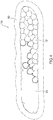
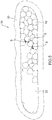
- Fig.3 is a diagram diagrammatically illustrating the ultrasonic joint part of Fig. 2
- Fig. 4 is an enlarged diagram illustrating the ultrasonic joint part of Fig. 3 with dashed-two dotted lines and representing with solid lines the part which is present at the joint interface between the aluminum-based conductor exposed part and the copper-based conductor exposed part and at which both exposed parts contact (join)
- Fig. 5 is an enlarged diagram illustrating the ultrasonic joint part of Fig. 3 with dashed-two dotted lines and representing with solid lines spaces S (three spaces in Fig.
- Fig.6 is a diagram for describing a measurement method of the total contacting length L of the contacting part shown in Fig. 4 and the summed length x of the contour lines of the spaces S shown in Fig. 5 .
- total contacting length L is a summed length of the part which is present at the joint interface between the aluminum-based conductor exposed part 22 and the copper-based conductor exposed part 12 and at which the copper-based conductor exposed part 12 and the aluminum-based conductor exposed part 22 contact (join) based on cross-section observation of the ultrasonic joint part 30, and specifically means the total sum of the lengths of the solid lines shown in Fig. 4 .
- the "summed length x of a contour line of a space” is a summed length of a contour line of a space S formed at a part which is present at the joint interface between the aluminum-based conductor exposed part 22 and the copper-based conductor exposed part 12 and at which the copper-based conductor exposed part 12 and the aluminum-based conductor exposed part 22 are separate based on cross-section observation of the ultrasonic joint part 30, and specifically means, when the space S is present at only one location, a contour line length measured for the space S, and when the space S is present at plural locations (three locations in Fig. 5 ) as shown by the solid lines in Fig. 5 , the total sum of the contour lengths measured for spaces S at the respective plural locations.
- measurements on the total contacting length L and the summed length x of the contour line of the space were conducted by a method in which a cross-section of the ultrasonic joint part 30 is captured by using an optical microscope or an electron microscope and an extending shape of the joint interface (illustrated by the solid line in Fig 6 ) can be approximated as much as possible from the captured image or photograph, for example, by a method in which plural straight lines each having a length of 10 ⁇ m or less (for example, 10 ⁇ m) are used and connected in a line graph as illustrated in Fig. 6 .
- a difference in tensile strength between the copper-based conductor and the aluminum-based conductor is 100 MPa or more. Consequently, a material of one conductor exposed part (for example, the aluminum-based conductor exposed part 22) out of the copper-based conductor exposed part 12 and the aluminum-based conductor exposed part 22 can be made deformable compared with the other conductor exposed part (for example, the copper-based conductor exposed part 12), and therefore, by combining these conductors with each other, resulting configuration allows one conductor exposed part to be relatively significantly collapsed by pressurizing force during ultrasonic joining, and the one conductor exposed part is preferentially plastically deformed or melted in the space S unjoined (not in contact) which is likely to be formed between the copper-based conductor exposed part 12 and the aluminum-based conductor exposed part 22 forming the joint interface to fill the space S (gap). As a result, formation of an ultrasonic joint part having a sound joint
- tensile strength may be higher in the aluminum-based conductor than in the copper-based conductor or may be higher in the copper-based conductor than in the aluminum-based conductor to the contrary as long as the difference in tensile strength between the copper-based conductor and the aluminum-based conductor is 100 MPa or more, and therefore, a combination of the copper-based conductor and the aluminum-based conductor can be appropriately selected according to application.
- the manufacturing method of the electric wire connection structure 1 in the present invention at least includes a step of mainly preparing a copper-based conductor covered electric wire 10 and an aluminum-based conductor covered electric wire 20, a step of forming a copper-based conductor exposed part and an aluminum-based conductor exposed part, and a step of ultrasonically joining the copper-based conductor exposed part and the aluminum-based conductor exposed part to form an ultrasonic joint part.
- the copper-based conductor covered electric wire 10 having a copper-based conductor covered part 11 in which a copper-based conductor is covered with an insulating cover and an aluminum-based conductor covered electric wire 20 having an aluminum-based conductor covered part 21 in which an aluminum-based conductor is covered with an insulating cover are prepared.
- the materials described above can be respectively used, and it is preferable that the insulating cover is a polyvinyl chloride resin.
- the copper-based conductor is not particularly limited, but a copper-based conductor formed by twisting and bundling plural strands made of a copper-based material is preferable.
- a copper-based conductor formed by twisting and bundling seven copper-based strands and having a size (thickness) of 0.13 sq (0.13 mm 2 ) can be used.
- the aluminum-based conductor is not particularly limited, but an aluminum-based conductor formed by twisting and bundling plural strands made of an aluminum-based material is preferable.
- an aluminum-based conductor formed by twisting and bundling seven aluminum-based strands and having a size (thickness) of 0.75 sq (0.75 mm 2 ) can be used.
- the copper-based conductor covered electric wire and the aluminum-based conductor covered electric wire respectively form a copper-based conductor exposed part 12 and an aluminum-based conductor exposed part 22 each of which is exposed by stripping a part of the insulating cover in a predetermined length.
- a method for stripping the insulating cover is not particularly limited, but a tool or an instrument such as a wire stripper can be used, for example.
- the length of the insulating cover to be stripped in each of the covered electric wires 10 and 20 is appropriately designed according to the range of a region of each of the conductor exposed parts 12 and 22 to be ultrasonically joined, and the length of the insulating cover to be stripped is preferably 5 to 25 mm and more preferably 10 to 25 mm, for example.
- the ultrasonic joint part 30 is formed by ultrasonically joining the formed copper-based conductor exposed part 12 and aluminum-based conductor exposed part 22 in a state of being superposed.
- the ultrasonic joint part 30 may be formed by inserting an outer peripheral side of a conductor stacked part in which the copper-based conductor exposed part 12 and the aluminum-based conductor exposed part 22 are superposed to the inside of a joint tube 50 and subsequently ultrasonically joining these while applying pressure from an outer surface side of the joint tube 50.
- superposition of the copper-based conductor exposed part 12 and the aluminum-based conductor exposed part 22 may be achieved by preliminarily joining a bundle of strands forming the copper-based conductor exposed part 12 and a bundle of strands forming the aluminum-based conductor exposed part 22 and superposing the joined conductor exposed parts 12 and 22 with each other.
- the ultrasonic joining is conducted by applying parallel ultrasonic vibration to a joint surface 33 between the copper-based conductor exposed part 12 and the aluminum-based conductor exposed part 22 while applying pressurizing force in a vertical direction in a state in which the copper-based conductor exposed part 12 and the aluminum-based conductor exposed part 22 are superposed.
- aluminum is known to form a tough oxide coating on its surface once being exposed to oxygen in the air.
- dirt derived from a substance such as oil or dust adheres to a metal surface in some cases.
- motion of metal atoms becomes active due to heating with frictional heat to cause movement of metal atoms caused by diffusion.
- strong attracting force is mutually generated between the metal parts, and copper-based metal in the copper-based conductor exposed part 12 and aluminum-based metal in the aluminum-based conductor exposed part 22 are joined in a solid state.
- Fig. 7 is a schematic diagram for describing steps of superposing the copper-based conductor covered electric wire 10 and the aluminum-based conductor covered electric wire 22 and subsequently ultrasonically joining an interface of the copper-based conductor exposed part 22 and the aluminum-based conductor exposed part 12 in that state using an ultrasonic joining apparatus 40 to form the ultrasonic joint part 30 having the joint surface 33.
- shape retention by the ultrasonic joining apparatus 40 is performed by placing the copper-based conductor exposed part 12 and the aluminum-based conductor exposed part 22 in a state of being superposed between a pressurizing surface of a horn 41 and a pressurizing surface of an anvil 42, clipping the superposed copper-based conductor exposed part 12 and aluminum-based conductor exposed part 22 with the horn 41 and the anvil 42 from a vertical direction, and disposing work holding jigs (grinding jaws) 43 at both right and left sides so that the superposed state does not collapse.
- the ultrasonic joining apparatus 40 can conduct ultrasonic joining by allowing the horn 41 to oscillate ultrasonic vibration oscillating in a longitudinal direction X (arrow A1 in Fig. 5 ) while applying pressure to press in a pressurizing direction Z (arrow A2 in Fig. 7 ) with the anvil 42.
- Energy of the ultrasonic waves to be applied is not particularly limited but is preferably 100 to 800 Ws (J) and more preferably 200 to 700 Ws.
- a compression rate of the ultrasonic joint part is preferably in a range of 20 to 80%.
- the "compression rate" herein means a value obtained by dividing a decreased amount from a cross-sectional area before crimping by the cross-sectional area before crimping and multiplying it by 100.
- the ultrasonic vibration oscillated from the horn 41 propagates through the inside of one conductor exposed part (the copper-based conductor exposed part 12 in Fig. 7 ) in the pressurizing direction Z (arrow A31 in Fig. 2 ) and consequently propagates through the inside of the other conductor exposed part (the aluminum-based conductor exposed part 22 in Fig. 7 ) in the pressurizing direction Z (arrow A32 in Fig. 2 ) from the copper-based conductor exposed part 12 via an interface to be the joint surface 33 to form the joint surface 33 around the interface.
- the ultrasonic joint part 30 is formed.
- the joint interface of the ultrasonic joint part can effectively suppress an increase in electric resistance and a decrease in joining strength (pull-out strength) caused by crevice corrosion by a total contacting length L and a summed length x of a contour line of a space S satisfying the relational expression of (x/L) ⁇ 100 ⁇ 10%.
- a copper-based conductor covered electric wire 10 and an aluminum-based conductor covered electric wire 20 were prepared by covering a copper-based conductor having the composition, tensile strength, and the like shown in Table 1 with an insulating cover of polyvinyl chloride and by covering an aluminum-based conductor having the composition, tensile strength, and the like shown in Table 1 with an insulating cover of polyvinyl chloride, respectively. Thereafter, the tip side of each of the covered electric wires 10, 20 was stripped by about 1.5 cm by a wire stripper to form a copper-based conductor exposed part 12 in which the copper-based conductor was exposed and an aluminum-based conductor exposed part 22 in which the aluminum-based conductor was exposed.
- the copper-based conductor exposed part 12 of the copper-based conductor covered electric wire 10 and the aluminum-based conductor exposed part 22 of the aluminum-based conductor covered electric wire 20 thus formed were superposed and subsequently placed on a pedestal (horn side) of an ultrasonic joining apparatus (manufactured by Schunk GmbH) in a state of being superposed.
- the copper-based conductor exposed part 12 and the aluminum-based conductor exposed part 22 were placed on the pedestal (horn side) of the ultrasonic joining apparatus with a joint tube disposed at an outer peripheral side of the conductor stacked part in which the copper-based conductor exposed part 12 and the aluminum-based conductor exposed part 22 of the aluminum-based conductor covered electric wire 20 were superposed.
- ultrasonic waves were applied to the outer surface of the placed conductor stacked part or the outer surface of the joint tube in a state of being sandwiched by the horn and the anvil under the joining conditions shown in Table 1 while applying pressurizing force in the vertical direction to form an ultrasonic joint part integrated by ultrasonic joining.
- a corrosion test was conducted on each of the ultrasonic joint part thus obtained, electric resistance and pull-out strength were measured before and after the corrosion test, an increasing ratio of electric resistance and a decreasing ratio of pull-out strength after the corrosion test were calculated, and corrosion resistance was comprehensively evaluated from these calculated values.
- a total contacting length L and a summed length of a contour line of a space were measured by a method in which a cross-section of the ultrasonic joint part 30 is captured by using an optical microscope or an electron microscope and an extending shape of the joint interface (illustrated by the solid line in Fig 6 ) can be approximated as much as possible from the captured image or photograph, for example, by a method in which plural straight lines each having a length of 10 ⁇ m or less (for example, 10 ⁇ m) are used and connected in a line graph as illustrated in Fig. 6 .
- Corrosion tests were conducted by methods of salt spray testing specified in JIS Z2371:2015. Test conditions are as follows.
- the copper-based conductor of the copper-based conductor covered electric wire was attached to one electrode and the aluminum-based conductor of the aluminum-based conductor covered electric wire was attached to another electrode, and electric resistance was measured using a circuit element measuring device manufactured by HIOKI E. E. CORPORATION (product name: 3560 AC m ⁇ HiTESTER) to obtain a ratio (increasing ratio (%)) of the electric resistance of the test piece after the corrosion test increased compared with the electric resistance of the test piece before the corrosion test.
- the ultrasonic joint part and an electric wire part were fixed to a chuck, and pull-out strength was measured.
- a ratio (decreasing ratio (%)) of the pull-out strength of the test piece after the corrosion test decreased compared with the pull-out strength of the test piece before the corrosion test was obtained.
- each of the electric wire connection structures of Examples 1 to 10 had an increase ratio of electric resistance suppressed as low as 19% or less, had a decreasing ratio of pull-out strength suppressed as low as 15% or less after the corrosion test, and was excellent in corrosion resistant.
- the electric connection structures of Comparative Examples 1 and 2 were imperfectly joined and breakage of the joint part occurred in the electric connection structure of Comparative Example 4, and a sound ultrasonic joint part could not be formed in all of these cases.
- each of the electric connection structures of Comparative Examples 3 and 5 had an increasing ratio of electric resistance of 320% or more, had a decreasing ratio of pull-out strength of 50% or more after the corrosion test, and was poor in corrosion resistant.
- the electrical wire connection structure of the present invention allows an increase in electric resistance and a decrease in joining strength (pull-out strength) caused by crevice corrosion to be suppressed, is excellent in corrosion resistant, and can stably form a sound ultrasonic joint part, and therefore, the electrical wire connection structure of the present invention is not only suitably used as a connector of a wire harness for an automobile, and the like but also capable of being used for wiring between electronic devices, various mechanical apparatuses requiring a lot of electric wiring, and the like and can be expected to be applied to various fields.
Landscapes
- Engineering & Computer Science (AREA)
- Manufacturing & Machinery (AREA)
- Mechanical Engineering (AREA)
- Connections Effected By Soldering, Adhesion, Or Permanent Deformation (AREA)
- Manufacturing Of Electrical Connectors (AREA)
- Insulated Conductors (AREA)
Abstract
Description
- The present invention provides an electric wire connection structure having an ultrasonic joint part formed by a copper-based conductor exposed part and an aluminum-based conductor exposed part.
- As an electric wire connection structure formed by interconnecting electric wires to each other for electrical connection, there is a wire harness being routed in an automobile, for example, for power supply and signal transmission. Some wire harnesses are quite long, and when power is fed to each device from one power source, for example, if wiring from one power source is provided on a one-by-one basis, the number of wires increases to cause an increase in weight. Therefore, an electric wire routed is usually formed by one thick wire in a part from a connecting position with a power source to a position close to (a position in front of) each device and is branched to plural thin wires using a joint in the vicinity of each device from the viewpoint of weight reduction. Further, it is useful to use an aluminum-based material having a light weight as a conductor forming an electric wire instead of a copper-based material.
- As a joining method, a so-called resistant welding method in which a part to be welded is sandwiched by two electrodes, current is supplied thereto, and metals are joined to each other utilizing heat generated by electric resistance and pressurizing force may be used, for example.
- The resistant welding method can relatively easily form a sound joint part when conductor metals of electric wires to be joined are both copper-based materials. However, in a case where metals of different kinds like an Al-based conductor and a Cu-based conductor, for example, are joined with each other, a sound joint part cannot be formed, because only the Al conductor having a lower melting point melts and the Cu conductor having a higher melting point does not melt. Therefore, in order to join metals of different kinds with different melting points by the resistant welding method, the metals should be heated to a high temperature not less than any of melting points of respective metals to be joined in a short time, and joining conditions are difficult to be controlled. In addition, there is a problem in safety because of the high temperature heating.
- Therefore, an ultrasonic joining method capable of joining at normal temperature is usually used for joining different kinds of metals with each other. For example,
Patent Literature 1 describes a wire harness in which strands forming a conductor of an insulated electric wire are joined with each other and a strand and a metal sleeve (or metal foil, etc.) are joined. - In addition, a case where a copper-based conductor and an aluminum-based conductor are directly ultrasonically joined in a state of being superposed without using a metal sleeve is also supposed from the viewpoint of reducing the number of parts forming a wire harness.
- However, when a copper-based conductor and an aluminum-based conductor are superposed and ultrasonically joined, depending on a combination of conductor materials different from one other for the copper-based conductor and the aluminum-based conductor or according to change of joining conditions or the like, a defect part (a space) at which the conductors are not joined (not in contact) may become prone to be present at a joint interface between the copper-based conductor and the aluminum-based conductor forming an ultrasonic joint part. In such a case, there is a problem that a part of the aluminum-based conductor is anodically dissolved due to crevice corrosion, and an increase in electric resistance and a decrease in joining strength (pull-out strength) are easily caused.
- Patent Literature 1: Japanese Patent Application Publication No.
2010-44887 - An object of the present invention is to provide an electric wire connection structure in which an increase in electric resistance and a decrease in joining strength (pull-out strength) caused by crevice corrosion are effectively suppressed by optimizing characteristics of a joint interface of an ultrasonic joint part formed by a copper-based conductor exposed part and an aluminum-based conductor exposed part.
- As a result of intensively studying on the above problem, the present inventors have found that an increase in electric resistance and a decrease in joining strength (tensile strength) caused by crevice corrosion can be effectively suppressed in the following manner. In order to form an ultrasonic joint part with a copper-based conductor exposed part and an aluminum based conductor exposed part, one conductor exposed part out of the copper-based conductor exposed part and the aluminum-based conductor exposed part is made of a material more deformable than the other conductor exposed part, and preferably, conductors made of materials with a difference in tensile strength therebetween being 100 MPa or more are used in combination for a copper-based conductor and an aluminum-based conductor. Resulting configuration allows one conductor exposed part to be relatively significantly collapsed and easily plastically fluidized by pressurizing force during ultrasonic joining, and therefore, one conductor exposed part enters to a space unjoined (not in contact), which is likely to be formed between the copper-based conductor exposed part and the aluminum-based conductor exposed part forming a joint interface, through plastic flow to fill the space. As a result, formation of an ultrasonic joint part having a sound joint interface is made possible. The present invention has been completed thereby.
- That is, subject matters of the present invention are as follows.
- (1) An electric wire connection structure including one or more copper-based conductor covered electric wires having a copper-based conductor covered part in which a copper-based conductor made of copper or a copper alloy is covered with an insulating cover and a copper-based conductor exposed part in which a part of the insulating cover is stripped by a predetermined length to expose the copper-based conductor; and one or more aluminum-based conductor covered electric wires having an aluminum-based conductor covered part in which an aluminum-based conductor made of aluminum or an aluminum alloy is covered with an insulating cover and an aluminum-based conductor exposed part in which a part of the insulating cover is stripped by a predetermined length to expose the aluminum-based conductor, the electric wire connection structure including a joint part provided at a conductor stacked part in which the copper-based conductor exposed part and the aluminum-based conductor exposed part are superposed, the electric wire connection structure being characterized in that a joint interface of the joint part is provided by the aluminum-based conductor covered electric wire being melted so as to fill a gap of the copper-based conductor covered electric wire based on cross-section observation.
- (2) An electric wire connection structure including one or more copper-based conductor covered electric wires having a copper-based conductor covered part in which a copper-based conductor made of copper or a copper alloy is covered with an insulating cover and a copper-based conductor exposed part in which a part of the insulating cover is stripped by a predetermined length to expose the copper-based conductor; and one or more aluminum-based conductor covered electric wires having an aluminum-based conductor covered part in which an aluminum-based conductor made of aluminum or an aluminum alloy is covered with an insulating cover and an aluminum-based conductor exposed part in which a part of the insulating cover is stripped by a predetermined length to expose the aluminum-based conductor, the electric wire connection structure including an ultrasonic joint part provided at a conductor stacked part in which the copper-based conductor exposed part and the aluminum-based conductor exposed part are superposed, the electric wire connection structure being characterized in that a joint interface of the ultrasonic joint part satisfies a relational expression of (x/L) × 100 ≤ 10% where a total contacting length which is a summed length of a part at which the copper-based conductor exposed part and the aluminum-based conductor exposed part contact is L and a summed length of a contour line of a space formed at a part at which the copper-based conductor exposed part and the aluminum-based conductor exposed part are separate is x based on cross-section observation.
- (3) The electric wire connection structure described in (1) or (2) above, wherein a difference in tensile strength between the copper-based conductor and the aluminum-based conductor is 100 MPa or more.
- (4) The electric wire connection structure described in any one of (1) to (3) above, characterized in that the electric wire connection structure further includes a joint tube in which an ultrasonic joint part is provided at an outer peripheral side of the conductor stacked part.
- According to the present invention, provision of an electric wire connection structure in which an increase in electric resistance and a decrease in joining strength (pull-out strength) caused by crevice corrosion are effectively suppressed has become possible by an electric wire connection structure including one or more copper-based conductor covered electric wires having a copper-based conductor covered part in which a copper-based conductor made of copper or a copper alloy is covered with an insulating cover and a copper-based conductor exposed part in which a part of the insulating cover is stripped by a predetermined length to expose the copper-based conductor; and one or more aluminum-based conductor covered electric wires having an aluminum-based conductor covered part in which an aluminum-based conductor made of aluminum or an aluminum alloy is covered with an insulating cover and an aluminum-based conductor exposed part in which a part of the insulating cover is stripped by a predetermined length to expose the aluminum-based conductor, the electric wire connection structure including a joint part provide at a conductor stacked part in which the copper-based conductor exposed part and the aluminum-based conductor exposed part are superposed, with a joint interface of the joint part being provided by the aluminum-based conductor covered electric wire being melted so as to fill a gap of the copper-based conductor covered electric wire based on cross-section observation.
- In addition, according to the present invention, provision of an electric wire connection structure in which an increase in electric resistance and a decrease in joining strength (pull-out strength) caused by crevice corrosion are effectively suppressed has become possible by an electric wire connection structure including one or more copper-based conductor covered electric wires having a copper-based conductor covered part in which a copper-based conductor made of copper or a copper alloy is covered with an insulating cover and a copper-based conductor exposed part in which a part of the insulating cover is stripped by a predetermined length to expose the copper-based conductor; and one or more aluminum-based conductor covered electric wires having an aluminum-based conductor covered part in which an aluminum-based conductor made of aluminum or an aluminum alloy is covered with an insulating cover and an aluminum-based conductor exposed part in which a part of the insulating cover is stripped by a predetermined length to expose the aluminum-based conductor, the electric wire connection structure including an ultrasonic joint part provided at a conductor stacked part in which the copper-based conductor exposed part and the aluminum-based conductor exposed part are superposed, with a joint interface of the ultrasonic joint part satisfying a relational expression of (x/L) × 100 ≤ 10% where a total contacting length which is a summed length of a part at which the copper-based conductor exposed part and the aluminum-based conductor exposed part contact is L and a summed length of a contour line of a space formed at a part at which the copper-based conductor exposed part and the aluminum-based conductor exposed part are separate is x based on cross-section observation.
-
- [
Fig. 1 ] A perspective diagram of an electric wire connection structure of one embodiment according to the present invention. - [
Fig. 2 ] A sectional photograph of an ultrasonic joint part forming an electric wire connection structure of another embodiment according to the present invention. - [
Fig. 3 ] A diagram diagrammatically illustrating the ultrasonic joint part ofFig. 2 . - [
Fig. 4 ] A diagram illustrating with solid lines a part which is present at a joint interface between an aluminum-based conductor exposed part and a copper-based conductor exposed part forming the ultrasonic joint part ofFig. 3 and at which both exposed parts contact (join). - [
Fig. 5 ] A diagram illustrating with solid lines spaces which are present at the joint interface between the aluminum-based conductor exposed part and the copper-based conductor exposed part forming the ultrasonic joint part ofFig. 3 and which are formed at a part at which the exposed parts are separate. - [
Fig. 6 ] A diagram for describing a measurement method of a total contacting length L of the contacting part shown inFig. 4 and a sum x of contour line lengths of the spaces shown inFig. 5 . - [
Fig. 7 ] A schematic diagram for describing steps for superposing and ultrasonically joining a copper-based conductor exposed part and an aluminum-based conductor exposed part using an ultrasonic joining apparatus. - Hereinafter, embodiments according to the present invention will be described with reference to drawings below.
Fig. 1 is a perspective diagram of an electric wire connection structure of one embodiment according to the present invention. The shown electricwire connection structure 1 includes one or more copper-based conductor coveredelectric wires 10 having a copper-based conductor coveredpart 11 and a copper-based conductor exposedpart 12 and one or more aluminum-based conductor coveredelectric wires 20 having an aluminum-based conductor coveredpart 21 and an aluminum-based conductor exposedpart 22. In addition, the electricwire connection structure 1 has an ultrasonicjoint part 30 provided at a conductor stacked part in which the copper-based conductor exposedpart 12 and the aluminum-based conductor exposedpart 22 are superposed. - The electric
wire connection structure 1 of the present invention includes one or more copper-based conductor coveredelectric wires 10 having the copper-based conductor coveredpart 11 in which a copper-based conductor made of copper or a copper alloy is covered with an insulating cover and the copper-based conductor exposedpart 12 in which a part of the insulating cover is stripped by a predetermined length to expose the copper-based conductor; and one or more aluminum-based conductor coveredelectric wires 20 having the aluminum-based conductor coveredpart 21 in which an aluminum-based conductor made of aluminum or an aluminum alloy is covered with an insulating cover and the aluminum-based conductor exposedpart 22 in which a part of the insulating cover is stripped by a predetermined length to expose the aluminum-based conductor, and the electricwire connection structure 1 includes a joint part provided at a conductor stacked part in which the copper-based conductor exposed part and the aluminum-based conductor exposed part are superposed, with a joint interface of the joint part being provided by the aluminum-based conductor covered electric wire being melted so as to fill a gap of the copper-based conductor covered electric wire based on cross-section observation. - In addition, the electric
wire connection structure 1 of the present invention includes one or more copper-based conductor coveredelectric wires 10 having the copper-based conductor coveredpart 11 in which a copper-based conductor made of copper or a copper alloy is covered with an insulating cover and the copper-based conductor exposedpart 12 in which a part of the insulating cover is stripped by a predetermined length to expose the copper-based conductor; and one or more aluminum-based conductor coveredelectric wires 20 having the aluminum-based conductor coveredpart 21 in which an aluminum-based conductor made of aluminum or an aluminum alloy is covered with an insulating cover and the aluminum-based conductor exposedpart 22 in which a part of the insulating cover is stripped by a predetermined length to expose the aluminum-based conductor, and the electricwire connection structure 1 includes an ultrasonic joint part provided at a conductor stacked part in which the copper-based conductor exposed part and the aluminum-based conductor exposed part are superposed, with a joint interface of the ultrasonic joint part satisfying a relational expression of (x/L) × 100 ≤ 10% where a total contacting length which is a summed length of a part at which the copper-based conductor exposed part and the aluminum-based conductor exposed part contact is L and a summed length of a contour line of a space formed at a part at which the copper-based conductor exposed part and the aluminum-based conductor exposed part are separate is x based on cross-section observation. Each element forming the electricwire connection structure 1 is as follows, and the electricwire connection structure 10 like this can effectively suppress an increase in electric resistance and a decrease in joining strength (pull-out strength) caused by crevice corrosion. - The copper-based conductor covered
electric wire 10 used in the present invention has the copper-based conductor coveredpart 11 in which a copper-based conductor made of copper or a copper alloy is covered with an insulating cover and the copper-based conductor exposedpart 12 in which a part of the insulating cover is stripped by a predetermined length to expose the copper-based conductor. The copper-based conductor coveredelectric wire 10 may be one covered electric wire in which a copper-based conductor formed by bundling plural strands made of a copper-based material is covered with an insulating cover or may be plural covered electric wires formed by bundling such covered electric wires, for example. In addition, while it is preferable that the copper-based conductor is formed by twisting strands to have a predetermined cross-sectional area, the copper-based conductor is not limited to this form and may be formed by a single wire. A strand diameter and the number of strands forming the copper-based conductor are not particularly limited, but it is preferable that the diameter of a strand is within a range of 0.05 to 1 mm and the number of strands is within a range of 7 to 90, for example. - The copper-based conductor is not particularly limited, but pure copper such as tough pitch copper, oxygen-free copper, and phosphorous-deoxidized copper, brass, phosphor bronze, a corson-type copper alloy (Cu-NiSi-based alloy), and the like may be used, for example.
- As such copper or a copper alloy, pure copper of alloy number C1000 series, a Cu-Zn-based alloy of alloy number C2000 series, a Cu-Sn-based alloy of alloy number C5000 series, and a Cu-Al-based alloy of alloy number C6000 series according to the standard of JIS H 3100:2012 can be used, for example.
- The insulating cover is not particularly limited as long as it is a material having insulation properties, but a halogen-based resin containing polyvinyl chloride, crosslinked polyvinyl chloride, chloroprene rubber, or the like as a main component or a halogen-free resin containing polyethylene, crosslinked polyethylene, ethylene propylene rubber, silicone rubber, polyester, or the like as a main component, and the like can be used as a resin material forming the insulating cover, for example, and a polyvinyl chloride resin is especially used. In addition, an additive such as a plasticizer, a flame retardant, and the like may be included in these resin materials as needed.
- The copper-based conductor covered
part 11 represents a part of the copper-based conductor where the copper-based conductor is not exposed and covered with the insulating cover in the copper-based conductor coveredelectric wire 10 in which the copper-based conductor is covered with the insulating cover. The copper-based conductor coveredpart 11 is a part of the original copper-based conductor free from an influence from ultrasonic waves described later. - The copper-based conductor exposed
part 12 represents a part where the copper-based conductor is exposed by stripping a part of the insulating cover by a predetermined length. The copper-based conductor exposedpart 12 is a part of the copper-based conductor to which ultrasonic waves are applied as described later, and forms theultrasonic joint part 30 together with the aluminum-based conductor exposedpart 22 responding to ultrasonic waves. The length of the insulating cover to be stripped is not particularly limited as long as the copper-based conductor exposedpart 12 has a length enough to be ultrasonically joined with the aluminum-based conductor exposedpart 22, and the length of the insulating cover to be stripped can be appropriately set according to the range of a region to be joined with the corresponding aluminum-based conductor exposedpart 22. The length of the copper-based conductor exposedpart 12, that is, the length of the insulating cover to be stripped is preferably 5 to 25 mm and more preferably 10 to 20 mm, for example. - The aluminum-based covered
electric wire 20 used in the present invention has the aluminum-based conductor coveredpart 21 in which an aluminum-based conductor is covered with an insulating cover and the aluminum-based conductor exposedpart 22 in which a part of the insulating cover is stripped by a predetermined length to expose the aluminum-based conductor. The aluminum-based coveredelectric wire 20 may be one covered electric wire in which an aluminum-based conductor formed by bundling plural strands made of an aluminum-based material is covered with an insulating cover or may be plural covered electric wires formed by bundling such covered electric wires, for example. In addition, while it is preferable that the aluminum-based conductor is formed by twisting strands to have a predetermined cross-sectional area, the aluminum-based conductor is not limited to this form and may be formed by a single wire. A strand diameter and the number of strands forming the aluminum-based conductor are not particularly limited, but it is preferable that the diameter of a strand is within a range of 0.05 to 1 mm and the number of strands is within a range of 7 to 90, for example. - The aluminum-based conductor is not particularly limited, but pure aluminum (Al) and aluminum alloys such as an aluminum-manganese-based alloy (Al-Mn-based alloy), an aluminum-magnesium-based alloy (Al-Mg-based alloy), an aluminum-magnesium-silicon-based alloy (Al-Mg-Si-based alloy), an aluminum-zinc-magnesium-based alloy (Al-Zn-Mg-based alloy), and an aluminum-copper-magnesium-based alloy (Al-Cu-Mg alloy) can be used, for example. An aluminum alloy is preferable from the viewpoint of imparting higher strength.
- As such aluminum or an aluminum alloy, pure aluminum of alloy number 1050, 1060, 1070, 1100, or 1200, an Al-Mn-based alloy of alloy number 3003 or 3203, an Al-Mg-based alloy of alloy number 5052, 5454, 5083, or 5086, an Al-Mg-Si-based alloy of alloy number 6101, 6N01, 6005A, 6060, 6061, 6063, or 6082, an Al-Zn-Mg-based alloy of alloy number 7003, 7N01, 7005, 7020, 7050, or 7075, and an Al-Cu-Mg alloy of alloy number 2014, 2014A, 2017, 2017A, or 2024 according to the standard of JIS H 4100:2015 can be used, for example.
- The insulating cover is not particularly limited as long as it is a material having insulation properties, but a halogen-based resin containing polyvinyl chloride, crosslinked polyvinyl chloride, chloroprene rubber, or the like as a main component or a halogen-free resin containing polyethylene, crosslinked polyethylene, ethylene propylene rubber, silicone rubber, polyester, or the like as a main component, and the like can be used as a resin material forming the insulating cover, for example, and a polyvinyl chloride resin is especially used. In addition, an additive such as a plasticizer, a flame retardant, and the like may be included in these resin materials as needed.
- The aluminum-based conductor covered
part 21 represents a part of the aluminum-based conductor where the aluminum-based conductor is not exposed and covered with the insulating cover in the coveredelectric wire 1 in which the aluminum-based conductor is covered with the insulating cover. The aluminum-based conductor coveredpart 21 is a part of the original aluminum-based conductor free from an influence from ultrasonic waves described later. - The aluminum-based conductor exposed
part 22 represents a part where the aluminum-based conductor is exposed by stripping a part of the insulating cover by a predetermined length. The aluminum-based conductor exposedpart 22 is a part of the aluminum-based conductor to which ultrasonic waves are applied as described later, and forms the ultrasonicjoint part 30 together with the copper-based conductor exposedpart 12 responding to ultrasonic waves. The length of the insulating cover to be stripped is not particularly limited as long as the aluminum-based conductor exposedpart 22 has a length enough to be joined with the copper-based conductor exposedpart 12, and the length of the insulating cover to be stripped can be appropriately set according to the range of a region to be joined with the corresponding copper-based conductor exposedpart 12. The length of the aluminum-based conductor exposedpart 22, that is, the length of the insulating cover to be stripped is preferably 5 to 25 mm and more preferably 10 to 20 mm, for example. - The electric
wire connection structure 10 of the present invention has the ultrasonicjoint part 30 formed by the copper-based conductor exposedpart 12 and the aluminum-based conductor exposedpart 22. In addition, the ultrasonicjoint part 30 can be integrally formed by further including ajoint tube 50 at an outer peripheral side of the conductor stacked part at which the copper-based conductor exposedpart 12 and the aluminum-based conductor exposedpart 22 are superposed.Fig. 2 shows a sectional photograph of an electric wire connection structure having an ultrasonicjoint part 30 provided with ajoint tube 50 at the outer peripheral side of the conductor stacked part. - Then, a major constitutional feature of the present invention is to optimize characteristics of the joint interface of the ultrasonic
joint part 30 provided by ultrasonic joining, and in particular to satisfy the relational expression of (x/L) × 100 ≤ 10% where a total contacting length which is a summed length of a part at which the copper-based conductor exposedpart 12 and the aluminum-based conductor exposedpart 22 contact (join) is L and a summed length of a contour line of a space S formed at a part at which the copper-based conductor exposedpart 12 and the aluminum-based conductor exposedpart 22 are separate is x based on cross-section observation of the ultrasonicjoint part 30, and an increase in electric resistance and a decrease in joining strength (tensile strength) caused by crevice corrosion are effectively suppressed thereby. - Here, the reason why the total contacting length L and the summed length x of the contour line of the space are made to satisfy the relational expression of (x/L) × 100 ≤ 10% is that when a value of (x/L) × 100 is larger than 10%, the part which is present at the joint interface of the ultrasonic
joint part 30 and at which the copper-based conductor exposedpart 12 and the aluminum-based conductor exposedpart 22 are separate increases, the space which causes generation of crevice corrosion increases in its number or volume, and an increase in electric resistance and a decrease in joining strength (pull-out strength) become remarkable. -
Fig.3 is a diagram diagrammatically illustrating the ultrasonic joint part ofFig. 2 ,Fig. 4 is an enlarged diagram illustrating the ultrasonic joint part ofFig. 3 with dashed-two dotted lines and representing with solid lines the part which is present at the joint interface between the aluminum-based conductor exposed part and the copper-based conductor exposed part and at which both exposed parts contact (join),Fig. 5 is an enlarged diagram illustrating the ultrasonic joint part ofFig. 3 with dashed-two dotted lines and representing with solid lines spaces S (three spaces inFig. 5 ) which are present at the joint interface between the aluminum-based conductor exposed part and the copper-based conductor exposed part and which are formed at the part at which the exposed parts are separate from each other, andFig.6 is a diagram for describing a measurement method of the total contacting length L of the contacting part shown inFig. 4 and the summed length x of the contour lines of the spaces S shown inFig. 5 . - Here, the "total contacting length L" is a summed length of the part which is present at the joint interface between the aluminum-based conductor exposed
part 22 and the copper-based conductor exposedpart 12 and at which the copper-based conductor exposedpart 12 and the aluminum-based conductor exposedpart 22 contact (join) based on cross-section observation of the ultrasonicjoint part 30, and specifically means the total sum of the lengths of the solid lines shown inFig. 4 . - In addition, the "summed length x of a contour line of a space" is a summed length of a contour line of a space S formed at a part which is present at the joint interface between the aluminum-based conductor exposed
part 22 and the copper-based conductor exposedpart 12 and at which the copper-based conductor exposedpart 12 and the aluminum-based conductor exposedpart 22 are separate based on cross-section observation of the ultrasonicjoint part 30, and specifically means, when the space S is present at only one location, a contour line length measured for the space S, and when the space S is present at plural locations (three locations inFig. 5 ) as shown by the solid lines inFig. 5 , the total sum of the contour lengths measured for spaces S at the respective plural locations. - Incidentally, measurements on the total contacting length L and the summed length x of the contour line of the space were conducted by a method in which a cross-section of the ultrasonic
joint part 30 is captured by using an optical microscope or an electron microscope and an extending shape of the joint interface (illustrated by the solid line inFig 6 ) can be approximated as much as possible from the captured image or photograph, for example, by a method in which plural straight lines each having a length of 10 µm or less (for example, 10 µm) are used and connected in a line graph as illustrated inFig. 6 . - In addition, in the electric wire connection structure of the present invention, it is preferable that a difference in tensile strength between the copper-based conductor and the aluminum-based conductor is 100 MPa or more. Consequently, a material of one conductor exposed part (for example, the aluminum-based conductor exposed part 22) out of the copper-based conductor exposed
part 12 and the aluminum-based conductor exposedpart 22 can be made deformable compared with the other conductor exposed part (for example, the copper-based conductor exposed part 12), and therefore, by combining these conductors with each other, resulting configuration allows one conductor exposed part to be relatively significantly collapsed by pressurizing force during ultrasonic joining, and the one conductor exposed part is preferentially plastically deformed or melted in the space S unjoined (not in contact) which is likely to be formed between the copper-based conductor exposedpart 12 and the aluminum-based conductor exposedpart 22 forming the joint interface to fill the space S (gap). As a result, formation of an ultrasonic joint part having a sound joint interface is made possible, and an increase in electric resistance and a decrease in joining strength (pull-out strength) caused by crevice corrosion can be more effectively suppressed. - Incidentally, measurements of tensile strength were conducted three times, and an average value thereof was obtained according to JIS Z 2241.
- Incidentally, in the electric wire connection structure of the present invention, tensile strength may be higher in the aluminum-based conductor than in the copper-based conductor or may be higher in the copper-based conductor than in the aluminum-based conductor to the contrary as long as the difference in tensile strength between the copper-based conductor and the aluminum-based conductor is 100 MPa or more, and therefore, a combination of the copper-based conductor and the aluminum-based conductor can be appropriately selected according to application.
- Next, a manufacturing method of the electric
wire connection structure 1 according to the present invention will be described. The manufacturing method of the electricwire connection structure 1 in the present invention at least includes a step of mainly preparing a copper-based conductor coveredelectric wire 10 and an aluminum-based conductor coveredelectric wire 20, a step of forming a copper-based conductor exposed part and an aluminum-based conductor exposed part, and a step of ultrasonically joining the copper-based conductor exposed part and the aluminum-based conductor exposed part to form an ultrasonic joint part. - First, the copper-based conductor covered
electric wire 10 having a copper-based conductor coveredpart 11 in which a copper-based conductor is covered with an insulating cover and an aluminum-based conductor coveredelectric wire 20 having an aluminum-based conductor coveredpart 21 in which an aluminum-based conductor is covered with an insulating cover are prepared. For the copper-based conductor and the insulating cover forming the copper-based conductor coveredelectric wire 10 and for the aluminum-based conductor and the insulating cover forming the aluminum-based conductor coveredelectric wire 20, the materials described above can be respectively used, and it is preferable that the insulating cover is a polyvinyl chloride resin. In addition, the copper-based conductor is not particularly limited, but a copper-based conductor formed by twisting and bundling plural strands made of a copper-based material is preferable. For example, a copper-based conductor formed by twisting and bundling seven copper-based strands and having a size (thickness) of 0.13 sq (0.13 mm2) can be used. In addition, the aluminum-based conductor is not particularly limited, but an aluminum-based conductor formed by twisting and bundling plural strands made of an aluminum-based material is preferable. For example, an aluminum-based conductor formed by twisting and bundling seven aluminum-based strands and having a size (thickness) of 0.75 sq (0.75 mm2) can be used. - Thereafter, the copper-based conductor covered electric wire and the aluminum-based conductor covered electric wire respectively form a copper-based conductor exposed
part 12 and an aluminum-based conductor exposedpart 22 each of which is exposed by stripping a part of the insulating cover in a predetermined length. A method for stripping the insulating cover is not particularly limited, but a tool or an instrument such as a wire stripper can be used, for example. The length of the insulating cover to be stripped in each of the coveredelectric wires parts - Further, the ultrasonic
joint part 30 is formed by ultrasonically joining the formed copper-based conductor exposedpart 12 and aluminum-based conductor exposedpart 22 in a state of being superposed. In addition, the ultrasonicjoint part 30 may be formed by inserting an outer peripheral side of a conductor stacked part in which the copper-based conductor exposedpart 12 and the aluminum-based conductor exposedpart 22 are superposed to the inside of ajoint tube 50 and subsequently ultrasonically joining these while applying pressure from an outer surface side of thejoint tube 50. - Incidentally, superposition of the copper-based conductor exposed
part 12 and the aluminum-based conductor exposedpart 22 may be achieved by preliminarily joining a bundle of strands forming the copper-based conductor exposedpart 12 and a bundle of strands forming the aluminum-based conductor exposedpart 22 and superposing the joined conductor exposedparts - The ultrasonic joining is conducted by applying parallel ultrasonic vibration to a
joint surface 33 between the copper-based conductor exposedpart 12 and the aluminum-based conductor exposedpart 22 while applying pressurizing force in a vertical direction in a state in which the copper-based conductor exposedpart 12 and the aluminum-based conductor exposedpart 22 are superposed. Generally, aluminum is known to form a tough oxide coating on its surface once being exposed to oxygen in the air. In addition, dirt derived from a substance such as oil or dust adheres to a metal surface in some cases. Interfaces between the copper-based conductor exposedpart 12 and the aluminum-based conductor exposedpart 22 rub against each other by friction caused by ultrasonic vibration to remove an oxide coating and an adhered substance on thejoint surface 33, and activated metal molecules appear on a clean joint surface. On further applying ultrasonic vibration, motion of metal atoms becomes active due to heating with frictional heat to cause movement of metal atoms caused by diffusion. Thereafter, strong attracting force is mutually generated between the metal parts, and copper-based metal in the copper-based conductor exposedpart 12 and aluminum-based metal in the aluminum-based conductor exposedpart 22 are joined in a solid state. - Since copper-based metal in the copper-based conductor exposed
part 12 and aluminum-based metal in the aluminum-based conductor exposedpart 22 are joined in a solid state, temperature rises not so high as to cause both metals to melt, and such ultrasonic joining can be conducted at a relatively low temperature (usually, about 35 to 50% of melting points of mother materials). Meanwhile, when parallel ultrasonic vibration is applied to thejoint surface 33 between the copper-based conductor exposedpart 12 and the aluminum-based conductor exposedpart 22, microscopic shear deformation due to ultrasonic vibration is generated, and consequently, the ultrasonicjoint part 30 formed by the copper-based conductor exposedpart 12 and the aluminum-based conductor exposedpart 22 is formed. -
Fig. 7 is a schematic diagram for describing steps of superposing the copper-based conductor coveredelectric wire 10 and the aluminum-based conductor coveredelectric wire 22 and subsequently ultrasonically joining an interface of the copper-based conductor exposedpart 22 and the aluminum-based conductor exposedpart 12 in that state using an ultrasonic joiningapparatus 40 to form the ultrasonicjoint part 30 having thejoint surface 33. - As illustrated in
Fig. 7 , for example, shape retention by the ultrasonic joiningapparatus 40 is performed by placing the copper-based conductor exposedpart 12 and the aluminum-based conductor exposedpart 22 in a state of being superposed between a pressurizing surface of ahorn 41 and a pressurizing surface of ananvil 42, clipping the superposed copper-based conductor exposedpart 12 and aluminum-based conductor exposedpart 22 with thehorn 41 and theanvil 42 from a vertical direction, and disposing work holding jigs (grinding jaws) 43 at both right and left sides so that the superposed state does not collapse. Thereafter, the ultrasonic joiningapparatus 40 can conduct ultrasonic joining by allowing thehorn 41 to oscillate ultrasonic vibration oscillating in a longitudinal direction X (arrow A1 inFig. 5 ) while applying pressure to press in a pressurizing direction Z (arrow A2 inFig. 7 ) with theanvil 42. Energy of the ultrasonic waves to be applied is not particularly limited but is preferably 100 to 800 Ws (J) and more preferably 200 to 700 Ws. In addition, a compression rate of the ultrasonic joint part is preferably in a range of 20 to 80%. Incidentally, the "compression rate" herein means a value obtained by dividing a decreased amount from a cross-sectional area before crimping by the cross-sectional area before crimping and multiplying it by 100. - As the ultrasonic joining
apparatus 40 operates in this way, the ultrasonic vibration oscillated from thehorn 41 propagates through the inside of one conductor exposed part (the copper-based conductor exposedpart 12 inFig. 7 ) in the pressurizing direction Z (arrow A31 inFig. 2 ) and consequently propagates through the inside of the other conductor exposed part (the aluminum-based conductor exposedpart 22 inFig. 7 ) in the pressurizing direction Z (arrow A32 inFig. 2 ) from the copper-based conductor exposedpart 12 via an interface to be thejoint surface 33 to form thejoint surface 33 around the interface. As a result, the ultrasonicjoint part 30 is formed. At this time, the joint interface of the ultrasonic joint part can effectively suppress an increase in electric resistance and a decrease in joining strength (pull-out strength) caused by crevice corrosion by a total contacting length L and a summed length x of a contour line of a space S satisfying the relational expression of (x/L) × 100 ≤ 10%. - Incidentally, the embodiments described above only exemplify several exemplary embodiments of the present invention, and various modifications can be made within the scope of the present invention.
- The present invention will be described in more detail based on the following examples, but the present invention is not limited to these examples.
- A copper-based conductor covered
electric wire 10 and an aluminum-based conductor coveredelectric wire 20 were prepared by covering a copper-based conductor having the composition, tensile strength, and the like shown in Table 1 with an insulating cover of polyvinyl chloride and by covering an aluminum-based conductor having the composition, tensile strength, and the like shown in Table 1 with an insulating cover of polyvinyl chloride, respectively. Thereafter, the tip side of each of the coveredelectric wires part 12 in which the copper-based conductor was exposed and an aluminum-based conductor exposedpart 22 in which the aluminum-based conductor was exposed. The copper-based conductor exposedpart 12 of the copper-based conductor coveredelectric wire 10 and the aluminum-based conductor exposedpart 22 of the aluminum-based conductor coveredelectric wire 20 thus formed were superposed and subsequently placed on a pedestal (horn side) of an ultrasonic joining apparatus (manufactured by Schunk GmbH) in a state of being superposed. Incidentally, with respect to Examples 1 to 3, the copper-based conductor exposedpart 12 and the aluminum-based conductor exposedpart 22 were placed on the pedestal (horn side) of the ultrasonic joining apparatus with a joint tube disposed at an outer peripheral side of the conductor stacked part in which the copper-based conductor exposedpart 12 and the aluminum-based conductor exposedpart 22 of the aluminum-based conductor coveredelectric wire 20 were superposed. Thereafter, ultrasonic waves were applied to the outer surface of the placed conductor stacked part or the outer surface of the joint tube in a state of being sandwiched by the horn and the anvil under the joining conditions shown in Table 1 while applying pressurizing force in the vertical direction to form an ultrasonic joint part integrated by ultrasonic joining. A corrosion test was conducted on each of the ultrasonic joint part thus obtained, electric resistance and pull-out strength were measured before and after the corrosion test, an increasing ratio of electric resistance and a decreasing ratio of pull-out strength after the corrosion test were calculated, and corrosion resistance was comprehensively evaluated from these calculated values. - A total contacting length L and a summed length of a contour line of a space were measured by a method in which a cross-section of the ultrasonic
joint part 30 is captured by using an optical microscope or an electron microscope and an extending shape of the joint interface (illustrated by the solid line inFig 6 ) can be approximated as much as possible from the captured image or photograph, for example, by a method in which plural straight lines each having a length of 10 µm or less (for example, 10 µm) are used and connected in a line graph as illustrated inFig. 6 . - Corrosion tests were conducted by methods of salt spray testing specified in JIS Z2371:2015. Test conditions are as follows.
-
- Test piece size: 200 mm (ultrasonic joint part + electric wire)
- Salt solution: neutral salt water
- Test temperature: 35°C
- pH: 7
- Pressure of compressed air: 0.1 MPa
- Test time: 96 h
- With respect to a test piece before being subjected to the above corrosion test and a test piece after being subjected to the above corrosion test, the copper-based conductor of the copper-based conductor covered electric wire was attached to one electrode and the aluminum-based conductor of the aluminum-based conductor covered electric wire was attached to another electrode, and electric resistance was measured using a circuit element measuring device manufactured by HIOKI E. E. CORPORATION (product name: 3560 AC mΩ HiTESTER) to obtain a ratio (increasing ratio (%)) of the electric resistance of the test piece after the corrosion test increased compared with the electric resistance of the test piece before the corrosion test.
- With respect to a test piece before being subjected to the above corrosion test and a test piece after being subjected to the above corrosion test, the ultrasonic joint part and an electric wire part were fixed to a chuck, and pull-out strength was measured. A ratio (decreasing ratio (%)) of the pull-out strength of the test piece after the corrosion test decreased compared with the pull-out strength of the test piece before the corrosion test was obtained.
- These evaluation results are shown in Table 2.
- Comprehensive evaluation was performed considering the results of the increasing ratio of electric resistance and the decreasing ratio of pull-out strength obtained after the above corrosion test. In comprehensive evaluation, the case where both of the increasing ratio in the electric resistance value and the decreasing ratio of pull-out strength were less than 10% was rated as "good," the case where both of the increasing ratio in the electric resistance value and the decreasing ratio of pull-out strength were less than 50% and at least one thereof was 10% or more was rated as "fair," the case where at least one of the increasing ratio in the electric resistance value and the decreasing ratio of pull-out strength was 50% or more was rated as "poor," and "good" and "fair" were regarded as acceptable levels in the present examples.
[Table 1] Conditions for manufacturing electric wire connection structure Conditions before ultrasonic joining Ultrasonic joining conditions Cu-based conductor covered electric wire Al-based conductor covered electric wire Difference in tensile strength |T1-T2| Presence or absence of arrangement of joint tube Compression rate Energy for joining Cu-based conductor Al-based conductor Type Number of strands Diameter of strand Tensile strength T1 Type Number of strands Diameter of strand Tensile strength T2 (mm) (MPa) (mm) (MPa) (MPa) (%) (Ws) Example 1 C1100-O 7 0.3 232 A1070-O 14 0.3 72 160 Present 80 200 Example 2 C1100-H 14 0.3 365 A1070-H18 14 0.3 131 234 Present 60 600 Example 3 C1020-O 14 0.3 270 A1060-O 11 0.1 70 200 Present 50 400 Example 4 C2700-O 14 0.3 360 A2011-T8 11 0.3 414 54 Absent 50 450 Example 5 C6140-F 57 0.1 577 A6061-T4 11 0.3 240 337 Absent 40 700 Example 6 C1100-O 21 0.3 232 A6061-T6 7 0.3 320 88 Absent 40 550 Example 7 C1100-O 14 0.8 232 A6070-T6 7 0.3 388 156 Absent 40 300 Example 8 C1201-O 38 0.8 220 A1070-O 7 0.3 72 148 Absent 40 400 Example 9 C1100-O 11 0.3 232 A1070-O 57 0.1 72 160 Absent 30 200 Example 10 0.7Sn-O 38 0.3 280 A1070-O 21 0.8 72 208 Absent 20 550 Comparative Example 1 C1100-O 7 0.3 232 A1070-O 7 0.3 72 160 Absent 40 50 Comparative Example 2 C1100-O 7 0.3 232 A6061-T4 7 0.3 240 8 Absent 10 300 Comparative Example 3 C1100-O 7 0.3 232 A6061-T4 11 0.3 240 8 Absent 40 300 Comparative Example 4 C1201-O 11 0.3 220 A6061-T4 11 0.3 240 20 Absent 90 300 Comparative Example 5 C1100-H 11 0.1 365 11 0.1 388 23 Absent 40 900 [Table 2] Total contacting length L Contour line Length of space x (x/L) × 100 Evaluation after corrosion test Comprehensive evaluation Increasing ratio of electric resistance Decreasing ratio of pull-out strength (mm) (mm) (%) (%) (%) Example 1 2.64 0.04 1.42% 7 7 Good Example 2 8.43 0.10 1.23% 5 4 Good Example 3 4.02 0.20 5.03% 12 9 Fair Example 4 1.18 0.10 8.18% 19 15 Fair Example 5 9.37 0.10 1.08% 3 5 Good Example 6 1.92 0.10 5.20% 13 7 Fair Example 7 1.89 0.10 5.32% 11 12 Fair Example 8 2.37 0.20 8.41% 12 10 Fair Example 9 3.12 0.30 9.74% 10 10 Fair Example 10 2.30 0.10 4.36% 6 3 Good Comparative Example 1 Imperfect joining Unmeasurable Unmeasurable Poor Comparative Example 2 Imperfect joining Unmeasurable Unmeasurable Poor Comparative Example 3 0.93 0.31 33.01% 320 50 Poor Comparative Example 4 Breakage of joint part Unmeasurable Unmeasurable Poor Comparative Example 5 1.32 0.82 62.00% 500 80 Poor - From the evaluation results shown in Table 2, each of the electric wire connection structures of Examples 1 to 10 had an increase ratio of electric resistance suppressed as low as 19% or less, had a decreasing ratio of pull-out strength suppressed as low as 15% or less after the corrosion test, and was excellent in corrosion resistant. On the other hand, the electric connection structures of Comparative Examples 1 and 2 were imperfectly joined and breakage of the joint part occurred in the electric connection structure of Comparative Example 4, and a sound ultrasonic joint part could not be formed in all of these cases. Further, each of the electric connection structures of Comparative Examples 3 and 5 had an increasing ratio of electric resistance of 320% or more, had a decreasing ratio of pull-out strength of 50% or more after the corrosion test, and was poor in corrosion resistant.
- The electrical wire connection structure of the present invention allows an increase in electric resistance and a decrease in joining strength (pull-out strength) caused by crevice corrosion to be suppressed, is excellent in corrosion resistant, and can stably form a sound ultrasonic joint part, and therefore, the electrical wire connection structure of the present invention is not only suitably used as a connector of a wire harness for an automobile, and the like but also capable of being used for wiring between electronic devices, various mechanical apparatuses requiring a lot of electric wiring, and the like and can be expected to be applied to various fields.
-
- 1
- electric wire connection structure
- 10
- copper-based conductor covered electric wire
- 11
- copper-based conductor covered part
- 12
- copper-based conductor exposed part
- 20
- aluminum-based conductor covered electric wire
- 21
- aluminum-based conductor covered part
- 22
- aluminum-based conductor exposed part
- 30
- ultrasonic joint part
- 33
- joint surface
- 40
- ultrasonic joining apparatus
- 41
- horn (or sonotrode)
- 42
- anvil
- 43
- work holding jig (grinding jaw)
- 50
- joint tube
Claims (4)
- An electric wire connection structure comprising:one or more copper-based conductor covered electric wires having a copper-based conductor covered part in which a copper-based conductor made of copper or a copper alloy is covered with an insulating cover and a copper-based conductor exposed part in which a part of the insulating cover is stripped by a predetermined length to expose the copper-based conductor; andone or more aluminum-based conductor covered electric wires having an aluminum-based conductor covered part in which an aluminum-based conductor made of aluminum or an aluminum alloy is covered with an insulating cover and an aluminum-based conductor exposed part in which a part of the insulating cover is stripped by a predetermined length to expose the aluminum-based conductor, whereina joint part is provided at a conductor stacked part in which the copper-based conductor exposed part and the aluminum-based conductor exposed part are superposed,the electric wire connection structure being characterized in thata joint interface of the joint part is provided by the aluminum-based conductor covered electric wire being melted so as to fill a gap of the copper-based conductor covered electric wire based on cross-section observation.
- An electric wire connection structure comprising:one or more copper-based conductor covered electric wires having a copper-based conductor covered part in which a copper-based conductor made of copper or a copper alloy is covered with an insulating cover and a copper-based conductor exposed part in which a part of the insulating cover is stripped by a predetermined length to expose the copper-based conductor; andone or more aluminum-based conductor covered electric wires having an aluminum-based conductor covered part in which an aluminum-based conductor made of aluminum or an aluminum alloy is covered with an insulating cover and an aluminum-based conductor exposed part in which a part of the insulating cover is stripped by a predetermined length to expose the aluminum-based conductor, whereinan ultrasonic joint part is provided at a conductor stacked part in which the copper-based conductor exposed part and the aluminum-based conductor exposed part are superposed,the electric wire connection structure being characterized in thata joint interface of the ultrasonic joint part satisfies a relational expression of

- The electric wire connection structure according to claim 1 or 2, wherein a difference in tensile strength between the copper-based conductor and the aluminum-based conductor is 100 MPa or more.
- The electric wire connection structure according to any one of claims 1 to 3, characterized in that the electric wire connection structure further comprises a joint tube in which an ultrasonic joint part is provided at an outer peripheral side of the conductor stacked part.
Applications Claiming Priority (2)
| Application Number | Priority Date | Filing Date | Title |
|---|---|---|---|
| JP2017121107 | 2017-06-21 | ||
| PCT/JP2018/022056 WO2018235637A1 (en) | 2017-06-21 | 2018-06-08 | Wire connection structure |
Publications (3)
| Publication Number | Publication Date |
|---|---|
| EP3644443A1 true EP3644443A1 (en) | 2020-04-29 |
| EP3644443A4 EP3644443A4 (en) | 2021-04-07 |
| EP3644443B1 EP3644443B1 (en) | 2025-04-02 |
Family
ID=64737621
Family Applications (1)
| Application Number | Title | Priority Date | Filing Date |
|---|---|---|---|
| EP18819724.8A Active EP3644443B1 (en) | 2017-06-21 | 2018-06-08 | Wire connection structure |
Country Status (5)
| Country | Link |
|---|---|
| US (1) | US11387581B2 (en) |
| EP (1) | EP3644443B1 (en) |
| JP (1) | JP6989605B2 (en) |
| CN (1) | CN110785894B (en) |
| WO (1) | WO2018235637A1 (en) |
Families Citing this family (4)
| Publication number | Priority date | Publication date | Assignee | Title |
|---|---|---|---|---|
| JP7044958B2 (en) * | 2018-10-25 | 2022-03-31 | 株式会社オートネットワーク技術研究所 | Wire connection structure and wire connection method |
| JP7435338B2 (en) * | 2020-07-27 | 2024-02-21 | 住友電装株式会社 | Terminal structure and sleeve of shielded wire |
| WO2022215826A1 (en) * | 2021-04-05 | 2022-10-13 | 엘에스전선 주식회사 | Power cable system having different-type conductor junction, and power cable connection method using different-type conductors |
| CN113593748B (en) * | 2021-05-27 | 2023-10-10 | 福建明锐新材料科技有限公司 | Alloy copper wire and preparation method thereof |
Family Cites Families (32)
| Publication number | Priority date | Publication date | Assignee | Title |
|---|---|---|---|---|
| US2946119A (en) * | 1956-04-23 | 1960-07-26 | Aeroprojects Inc | Method and apparatus employing vibratory energy for bonding metals |
| US3002270A (en) * | 1957-04-03 | 1961-10-03 | Sonobond Corp | Method and apparatus for bonding metals |
| US3056192A (en) * | 1957-12-30 | 1962-10-02 | Sonobond Corp | Vibratory welding process and apparatus |
| US3039333A (en) * | 1958-06-03 | 1962-06-19 | Aeroprojects Inc | Apparatus for introducing high levels of vibratory energy to a work area |
| US3648014A (en) * | 1969-07-15 | 1972-03-07 | Gen Electric | Method of joining copper braid to aluminum and the joint formed thereby |
| US4038743A (en) * | 1972-05-18 | 1977-08-02 | Essex International, Inc. | Terminating and splicing electrical conductors |
| US4224499A (en) * | 1978-10-20 | 1980-09-23 | General Electric Company | Laser welding aluminum to copper |
| FR2555084B1 (en) * | 1983-11-23 | 1987-05-22 | Paris & Du Rhone | METHOD OF WELDING AT LEAST ONE ALUMINUM WIRE ON A COPPER WORKPIECE |
| JPH0721843U (en) | 1993-09-22 | 1995-04-21 | ヤマハ株式会社 | Wall panels |
| DE19908031B4 (en) * | 1999-02-24 | 2009-08-13 | Auto-Kabel Management Gmbh | Connection of an electrical aluminum cable with a connector made of copper or the like metal |
| JP3578142B2 (en) * | 2002-01-15 | 2004-10-20 | 株式会社日立製作所 | Connection structure, connection method thereof, rotating electric machine and AC generator using the same |
| JP3918724B2 (en) | 2002-11-28 | 2007-05-23 | トヨタ自動車株式会社 | Manufacturing method of semiconductor device in which wires are bonded |
| JP4550791B2 (en) * | 2005-11-24 | 2010-09-22 | 古河電気工業株式会社 | Aluminum stranded wire crimp terminal and aluminum stranded wire terminal structure to which the crimp terminal is connected |
| JP2007305314A (en) | 2006-05-08 | 2007-11-22 | Hitachi Cable Ltd | CABLE WITH CONNECTION TERMINAL AND METHOD FOR MANUFACTURING THE SAME, AND ULTRASONIC WELDING METHOD AND ULTRASONIC WELDER FOR CONNECTION TERMINAL AND CABLE |
| JP2009009736A (en) * | 2007-06-26 | 2009-01-15 | Auto Network Gijutsu Kenkyusho:Kk | Terminal connection structure to aluminum wire |
| JP2010044887A (en) | 2008-08-11 | 2010-02-25 | Autonetworks Technologies Ltd | Wire harness and method of manufacturing the same, and method of connecting insulation wire |
| JP5196562B2 (en) * | 2008-11-06 | 2013-05-15 | 矢崎総業株式会社 | Connection method of aluminum wire and copper wire and connection body thereof |
| JP5223798B2 (en) * | 2009-07-03 | 2013-06-26 | 日立電線株式会社 | Electric wire connection structure and vehicle conductive path having the electric wire connection structure |
| JP5660458B2 (en) * | 2010-02-16 | 2015-01-28 | 日立金属株式会社 | Electric wire with terminal and manufacturing method thereof |
| US8522471B2 (en) * | 2010-06-25 | 2013-09-03 | Pacific Aerospace & Electronics, Inc. | Firearms and firearm components comprising bonded multi-metallic materials; methods of manufacture |
| JP5820153B2 (en) * | 2011-06-17 | 2015-11-24 | 矢崎総業株式会社 | Inter-wire connection structure and manufacturing method thereof |
| JP2013004406A (en) | 2011-06-20 | 2013-01-07 | Hitachi Cable Ltd | Manufacturing method of wire with terminal |
| JP5860618B2 (en) * | 2011-06-20 | 2016-02-16 | 矢崎総業株式会社 | Wire connection method |
| JP5913851B2 (en) * | 2011-07-20 | 2016-04-27 | 矢崎総業株式会社 | Wire connection method |
| JP5892046B2 (en) * | 2012-11-15 | 2016-03-23 | 株式会社オートネットワーク技術研究所 | Connection structure and connection structure |
| JP5659274B1 (en) | 2013-07-18 | 2015-01-28 | 大電株式会社 | Connection method of metal conductor and metal terminal |
| DE102014006244A1 (en) * | 2014-04-28 | 2015-10-29 | Rosenberger Hochfrequenztechnik Gmbh & Co. Kg | Crimp weld |
| JP6622961B2 (en) | 2014-05-19 | 2019-12-18 | 古河電気工業株式会社 | Wire connection structure and wire connection method |
| DE112014006851T5 (en) * | 2014-07-31 | 2017-05-04 | Tabuchi Electric Co., Ltd. | Terminal connection structure and method for manufacturing the same |
| US10038292B2 (en) * | 2014-09-03 | 2018-07-31 | Yazaki Corporation | Method for connecting insulated wires |
| KR20210134087A (en) * | 2016-04-29 | 2021-11-08 | 누부루 인크. | Visible laser welding of electronic packaging, automotive electrics, battery and other components |
| EP3336859B1 (en) * | 2016-12-15 | 2019-10-09 | Aptiv Technologies Limited | Method to predict a strength of an ultrasonic weld-joint |
-
2018
- 2018-06-08 CN CN201880042148.8A patent/CN110785894B/en active Active
- 2018-06-08 WO PCT/JP2018/022056 patent/WO2018235637A1/en not_active Ceased
- 2018-06-08 JP JP2019525388A patent/JP6989605B2/en active Active
- 2018-06-08 EP EP18819724.8A patent/EP3644443B1/en active Active
-
2019
- 2019-12-19 US US16/721,535 patent/US11387581B2/en active Active
Also Published As
| Publication number | Publication date |
|---|---|
| CN110785894B (en) | 2020-12-29 |
| JP6989605B2 (en) | 2022-01-05 |
| JPWO2018235637A1 (en) | 2020-04-23 |
| US20200136277A1 (en) | 2020-04-30 |
| US11387581B2 (en) | 2022-07-12 |
| WO2018235637A1 (en) | 2018-12-27 |
| EP3644443B1 (en) | 2025-04-02 |
| EP3644443A4 (en) | 2021-04-07 |
| CN110785894A (en) | 2020-02-11 |
Similar Documents
| Publication | Publication Date | Title |
|---|---|---|
| US11387581B2 (en) | Electric wire connection structure | |
| JP5235369B2 (en) | Wire harness, method for manufacturing the same, and method for connecting insulated wires | |
| JP5660458B2 (en) | Electric wire with terminal and manufacturing method thereof | |
| CN104094472B (en) | The compression bonding method of crimp type terminal, connection tectosome, connector and crimp type terminal | |
| US8627996B2 (en) | System and method for terminating aluminum conductors | |
| WO2014129217A1 (en) | Method for manufacturing electrical wiring connection structure body, and electrical wiring connection structure body | |
| CN109861010A (en) | Terminal connection method and terminal | |
| US9793625B2 (en) | Electric wire with connecting terminal and method for manufacturing such electric wire | |
| JP2013004406A (en) | Manufacturing method of wire with terminal | |
| JP5369637B2 (en) | Electric wire with terminal fitting and method for manufacturing the same | |
| JP2014032819A (en) | Aluminum electric wire | |
| US20140262501A1 (en) | Durable copper to aluminum welded connection | |
| CN112074993B (en) | Wire connection structure and wire connection method | |
| JP2016001590A (en) | Wire connection structure and wire connection method | |
| JP2016001551A (en) | Cable and wire with crimped terminal | |
| JP7132699B2 (en) | Wire connection structure and manufacturing method thereof | |
| JP6316230B2 (en) | Electric wire with connection terminal and method of manufacturing the electric wire | |
| JP2011258468A (en) | Terminal, electric wire with terminal and method for producing the same | |
| JP5786590B2 (en) | Electric wire, electric wire with terminal fittings, and method of manufacturing electric wire with terminal fittings | |
| KR102000372B1 (en) | Electrical wire-connecting structure and method for manufacturing electrical wire-connecting structure | |
| JP5223798B2 (en) | Electric wire connection structure and vehicle conductive path having the electric wire connection structure | |
| WO2019181633A1 (en) | Connection structure of electric wires, and method for producing harness | |
| JP2021034287A (en) | Connection structure | |
| JP2023170102A (en) | Wire welding method | |
| JP2025170464A (en) | Manufacturing method of electric wire with terminal |
Legal Events
| Date | Code | Title | Description |
|---|---|---|---|
| STAA | Information on the status of an ep patent application or granted ep patent |
Free format text: STATUS: THE INTERNATIONAL PUBLICATION HAS BEEN MADE |
|
| PUAI | Public reference made under article 153(3) epc to a published international application that has entered the european phase |
Free format text: ORIGINAL CODE: 0009012 |
|
| STAA | Information on the status of an ep patent application or granted ep patent |
Free format text: STATUS: REQUEST FOR EXAMINATION WAS MADE |
|
| 17P | Request for examination filed |
Effective date: 20191230 |
|
| AK | Designated contracting states |
Kind code of ref document: A1 Designated state(s): AL AT BE BG CH CY CZ DE DK EE ES FI FR GB GR HR HU IE IS IT LI LT LU LV MC MK MT NL NO PL PT RO RS SE SI SK SM TR |
|
| AX | Request for extension of the european patent |
Extension state: BA ME |
|
| DAV | Request for validation of the european patent (deleted) | ||
| DAX | Request for extension of the european patent (deleted) | ||
| RIC1 | Information provided on ipc code assigned before grant |
Ipc: H01R 4/02 20060101ALI20201126BHEP Ipc: H01B 7/00 20060101ALI20201126BHEP Ipc: H01R 43/02 20060101ALI20201126BHEP Ipc: H01R 4/72 20060101ALN20201126BHEP Ipc: H01R 4/62 20060101AFI20201126BHEP |
|
| A4 | Supplementary search report drawn up and despatched |
Effective date: 20210305 |
|
| RIC1 | Information provided on ipc code assigned before grant |
Ipc: H01R 4/02 20060101ALI20210301BHEP Ipc: H01R 4/72 20060101ALN20210301BHEP Ipc: H01B 7/00 20060101ALI20210301BHEP Ipc: H01R 4/62 20060101AFI20210301BHEP Ipc: H01R 43/02 20060101ALI20210301BHEP |
|
| STAA | Information on the status of an ep patent application or granted ep patent |
Free format text: STATUS: EXAMINATION IS IN PROGRESS |
|
| 17Q | First examination report despatched |
Effective date: 20230103 |
|
| GRAP | Despatch of communication of intention to grant a patent |
Free format text: ORIGINAL CODE: EPIDOSNIGR1 |
|
| STAA | Information on the status of an ep patent application or granted ep patent |
Free format text: STATUS: GRANT OF PATENT IS INTENDED |
|
| RIC1 | Information provided on ipc code assigned before grant |
Ipc: H01R 4/72 20060101ALN20241001BHEP Ipc: H01R 43/02 20060101ALI20241001BHEP Ipc: H01R 4/02 20060101ALI20241001BHEP Ipc: H01B 7/00 20060101ALI20241001BHEP Ipc: H01R 4/62 20060101AFI20241001BHEP |
|
| RIC1 | Information provided on ipc code assigned before grant |
Ipc: H01R 4/72 20060101ALN20241016BHEP Ipc: H01R 43/02 20060101ALI20241016BHEP Ipc: H01R 4/02 20060101ALI20241016BHEP Ipc: H01B 7/00 20060101ALI20241016BHEP Ipc: H01R 4/62 20060101AFI20241016BHEP |
|
| INTG | Intention to grant announced |
Effective date: 20241028 |
|
| RIN1 | Information on inventor provided before grant (corrected) |
Inventor name: MITOSE, KENGO Inventor name: TACHIBANA, AKIRA Inventor name: YOSHIDA, SHO |
|
| GRAS | Grant fee paid |
Free format text: ORIGINAL CODE: EPIDOSNIGR3 |
|
| GRAA | (expected) grant |
Free format text: ORIGINAL CODE: 0009210 |
|
| STAA | Information on the status of an ep patent application or granted ep patent |
Free format text: STATUS: THE PATENT HAS BEEN GRANTED |
|
| P01 | Opt-out of the competence of the unified patent court (upc) registered |
Free format text: CASE NUMBER: APP_6119/2025 Effective date: 20250205 |
|
| AK | Designated contracting states |
Kind code of ref document: B1 Designated state(s): AL AT BE BG CH CY CZ DE DK EE ES FI FR GB GR HR HU IE IS IT LI LT LU LV MC MK MT NL NO PL PT RO RS SE SI SK SM TR |
|
| REG | Reference to a national code |
Ref country code: GB Ref legal event code: FG4D |
|
| REG | Reference to a national code |
Ref country code: CH Ref legal event code: EP |
|
| REG | Reference to a national code |
Ref country code: IE Ref legal event code: FG4D |
|
| REG | Reference to a national code |
Ref country code: DE Ref legal event code: R096 Ref document number: 602018080760 Country of ref document: DE |
|
| PGFP | Annual fee paid to national office [announced via postgrant information from national office to epo] |
Ref country code: DE Payment date: 20250626 Year of fee payment: 8 |
|
| REG | Reference to a national code |
Ref country code: NL Ref legal event code: MP Effective date: 20250402 |
|
| PG25 | Lapsed in a contracting state [announced via postgrant information from national office to epo] |
Ref country code: NL Free format text: LAPSE BECAUSE OF FAILURE TO SUBMIT A TRANSLATION OF THE DESCRIPTION OR TO PAY THE FEE WITHIN THE PRESCRIBED TIME-LIMIT Effective date: 20250402 |
|
| REG | Reference to a national code |
Ref country code: AT Ref legal event code: MK05 Ref document number: 1782258 Country of ref document: AT Kind code of ref document: T Effective date: 20250402 |
|
| PG25 | Lapsed in a contracting state [announced via postgrant information from national office to epo] |
Ref country code: PT Free format text: LAPSE BECAUSE OF FAILURE TO SUBMIT A TRANSLATION OF THE DESCRIPTION OR TO PAY THE FEE WITHIN THE PRESCRIBED TIME-LIMIT Effective date: 20250804 Ref country code: ES Free format text: LAPSE BECAUSE OF FAILURE TO SUBMIT A TRANSLATION OF THE DESCRIPTION OR TO PAY THE FEE WITHIN THE PRESCRIBED TIME-LIMIT Effective date: 20250402 Ref country code: FI Free format text: LAPSE BECAUSE OF FAILURE TO SUBMIT A TRANSLATION OF THE DESCRIPTION OR TO PAY THE FEE WITHIN THE PRESCRIBED TIME-LIMIT Effective date: 20250402 |
|
| REG | Reference to a national code |
Ref country code: LT Ref legal event code: MG9D |
|
| PG25 | Lapsed in a contracting state [announced via postgrant information from national office to epo] |
Ref country code: GR Free format text: LAPSE BECAUSE OF FAILURE TO SUBMIT A TRANSLATION OF THE DESCRIPTION OR TO PAY THE FEE WITHIN THE PRESCRIBED TIME-LIMIT Effective date: 20250703 Ref country code: NO Free format text: LAPSE BECAUSE OF FAILURE TO SUBMIT A TRANSLATION OF THE DESCRIPTION OR TO PAY THE FEE WITHIN THE PRESCRIBED TIME-LIMIT Effective date: 20250702 |
|
| PG25 | Lapsed in a contracting state [announced via postgrant information from national office to epo] |
Ref country code: PL Free format text: LAPSE BECAUSE OF FAILURE TO SUBMIT A TRANSLATION OF THE DESCRIPTION OR TO PAY THE FEE WITHIN THE PRESCRIBED TIME-LIMIT Effective date: 20250402 |
|
| PG25 | Lapsed in a contracting state [announced via postgrant information from national office to epo] |
Ref country code: BG Free format text: LAPSE BECAUSE OF FAILURE TO SUBMIT A TRANSLATION OF THE DESCRIPTION OR TO PAY THE FEE WITHIN THE PRESCRIBED TIME-LIMIT Effective date: 20250402 |
|
| PG25 | Lapsed in a contracting state [announced via postgrant information from national office to epo] |
Ref country code: HR Free format text: LAPSE BECAUSE OF FAILURE TO SUBMIT A TRANSLATION OF THE DESCRIPTION OR TO PAY THE FEE WITHIN THE PRESCRIBED TIME-LIMIT Effective date: 20250402 |
|
| PG25 | Lapsed in a contracting state [announced via postgrant information from national office to epo] |
Ref country code: AT Free format text: LAPSE BECAUSE OF FAILURE TO SUBMIT A TRANSLATION OF THE DESCRIPTION OR TO PAY THE FEE WITHIN THE PRESCRIBED TIME-LIMIT Effective date: 20250402 |
|
| PG25 | Lapsed in a contracting state [announced via postgrant information from national office to epo] |
Ref country code: RS Free format text: LAPSE BECAUSE OF FAILURE TO SUBMIT A TRANSLATION OF THE DESCRIPTION OR TO PAY THE FEE WITHIN THE PRESCRIBED TIME-LIMIT Effective date: 20250702 |
|
| PG25 | Lapsed in a contracting state [announced via postgrant information from national office to epo] |
Ref country code: IS Free format text: LAPSE BECAUSE OF FAILURE TO SUBMIT A TRANSLATION OF THE DESCRIPTION OR TO PAY THE FEE WITHIN THE PRESCRIBED TIME-LIMIT Effective date: 20250802 |
|
| PG25 | Lapsed in a contracting state [announced via postgrant information from national office to epo] |
Ref country code: LV Free format text: LAPSE BECAUSE OF FAILURE TO SUBMIT A TRANSLATION OF THE DESCRIPTION OR TO PAY THE FEE WITHIN THE PRESCRIBED TIME-LIMIT Effective date: 20250402 |
|
| REG | Reference to a national code |
Ref country code: DE Ref legal event code: R097 Ref document number: 602018080760 Country of ref document: DE |
|
| PG25 | Lapsed in a contracting state [announced via postgrant information from national office to epo] |
Ref country code: DK Free format text: LAPSE BECAUSE OF FAILURE TO SUBMIT A TRANSLATION OF THE DESCRIPTION OR TO PAY THE FEE WITHIN THE PRESCRIBED TIME-LIMIT Effective date: 20250402 Ref country code: SM Free format text: LAPSE BECAUSE OF FAILURE TO SUBMIT A TRANSLATION OF THE DESCRIPTION OR TO PAY THE FEE WITHIN THE PRESCRIBED TIME-LIMIT Effective date: 20250402 |
|
| PG25 | Lapsed in a contracting state [announced via postgrant information from national office to epo] |
Ref country code: CZ Free format text: LAPSE BECAUSE OF FAILURE TO SUBMIT A TRANSLATION OF THE DESCRIPTION OR TO PAY THE FEE WITHIN THE PRESCRIBED TIME-LIMIT Effective date: 20250402 |
|
| PG25 | Lapsed in a contracting state [announced via postgrant information from national office to epo] |
Ref country code: EE Free format text: LAPSE BECAUSE OF FAILURE TO SUBMIT A TRANSLATION OF THE DESCRIPTION OR TO PAY THE FEE WITHIN THE PRESCRIBED TIME-LIMIT Effective date: 20250402 |
|
| PG25 | Lapsed in a contracting state [announced via postgrant information from national office to epo] |
Ref country code: RO Free format text: LAPSE BECAUSE OF FAILURE TO SUBMIT A TRANSLATION OF THE DESCRIPTION OR TO PAY THE FEE WITHIN THE PRESCRIBED TIME-LIMIT Effective date: 20250402 Ref country code: SK Free format text: LAPSE BECAUSE OF FAILURE TO SUBMIT A TRANSLATION OF THE DESCRIPTION OR TO PAY THE FEE WITHIN THE PRESCRIBED TIME-LIMIT Effective date: 20250402 |
|
| REG | Reference to a national code |
Ref country code: CH Ref legal event code: H13 Free format text: ST27 STATUS EVENT CODE: U-0-0-H10-H13 (AS PROVIDED BY THE NATIONAL OFFICE) Effective date: 20260127 |
|
| PG25 | Lapsed in a contracting state [announced via postgrant information from national office to epo] |
Ref country code: IT Free format text: LAPSE BECAUSE OF FAILURE TO SUBMIT A TRANSLATION OF THE DESCRIPTION OR TO PAY THE FEE WITHIN THE PRESCRIBED TIME-LIMIT Effective date: 20250402 |
|
| PG25 | Lapsed in a contracting state [announced via postgrant information from national office to epo] |
Ref country code: MC Free format text: LAPSE BECAUSE OF FAILURE TO SUBMIT A TRANSLATION OF THE DESCRIPTION OR TO PAY THE FEE WITHIN THE PRESCRIBED TIME-LIMIT Effective date: 20250402 |
|
| PLBE | No opposition filed within time limit |
Free format text: ORIGINAL CODE: 0009261 |
|
| STAA | Information on the status of an ep patent application or granted ep patent |
Free format text: STATUS: NO OPPOSITION FILED WITHIN TIME LIMIT |
|
| REG | Reference to a national code |
Ref country code: CH Ref legal event code: L10 Free format text: ST27 STATUS EVENT CODE: U-0-0-L10-L00 (AS PROVIDED BY THE NATIONAL OFFICE) Effective date: 20260211 |
|
| PG25 | Lapsed in a contracting state [announced via postgrant information from national office to epo] |
Ref country code: LU Free format text: LAPSE BECAUSE OF NON-PAYMENT OF DUE FEES Effective date: 20250608 |
|
| REG | Reference to a national code |
Ref country code: BE Ref legal event code: MM Effective date: 20250630 |
|
| 26N | No opposition filed |
Effective date: 20260105 |
|
| GBPC | Gb: european patent ceased through non-payment of renewal fee |
Effective date: 20250702 |
|
| PG25 | Lapsed in a contracting state [announced via postgrant information from national office to epo] |
Ref country code: GB Free format text: LAPSE BECAUSE OF NON-PAYMENT OF DUE FEES Effective date: 20250702 |
|
| PG25 | Lapsed in a contracting state [announced via postgrant information from national office to epo] |
Ref country code: IE Free format text: LAPSE BECAUSE OF NON-PAYMENT OF DUE FEES Effective date: 20250608 |
|
| PG25 | Lapsed in a contracting state [announced via postgrant information from national office to epo] |
Ref country code: BE Free format text: LAPSE BECAUSE OF NON-PAYMENT OF DUE FEES Effective date: 20250630 |
|
| PG25 | Lapsed in a contracting state [announced via postgrant information from national office to epo] |
Ref country code: FR Free format text: LAPSE BECAUSE OF NON-PAYMENT OF DUE FEES Effective date: 20250630 |
|
| PG25 | Lapsed in a contracting state [announced via postgrant information from national office to epo] |
Ref country code: CH Free format text: LAPSE BECAUSE OF NON-PAYMENT OF DUE FEES Effective date: 20250630 |