EP3644411A1 - Charging/discharging device, having reduced temperature difference, for secondary battery formation process - Google Patents
Charging/discharging device, having reduced temperature difference, for secondary battery formation process Download PDFInfo
- Publication number
- EP3644411A1 EP3644411A1 EP19765079.9A EP19765079A EP3644411A1 EP 3644411 A1 EP3644411 A1 EP 3644411A1 EP 19765079 A EP19765079 A EP 19765079A EP 3644411 A1 EP3644411 A1 EP 3644411A1
- Authority
- EP
- European Patent Office
- Prior art keywords
- charge
- wiring duct
- discharge
- exhaust fan
- wall
- Prior art date
- Legal status (The legal status is an assumption and is not a legal conclusion. Google has not performed a legal analysis and makes no representation as to the accuracy of the status listed.)
- Granted
Links
Images





Classifications
-
- H—ELECTRICITY
- H01—ELECTRIC ELEMENTS
- H01M—PROCESSES OR MEANS, e.g. BATTERIES, FOR THE DIRECT CONVERSION OF CHEMICAL ENERGY INTO ELECTRICAL ENERGY
- H01M10/00—Secondary cells; Manufacture thereof
- H01M10/42—Methods or arrangements for servicing or maintenance of secondary cells or secondary half-cells
- H01M10/44—Methods for charging or discharging
- H01M10/446—Initial charging measures
-
- H—ELECTRICITY
- H01—ELECTRIC ELEMENTS
- H01M—PROCESSES OR MEANS, e.g. BATTERIES, FOR THE DIRECT CONVERSION OF CHEMICAL ENERGY INTO ELECTRICAL ENERGY
- H01M4/00—Electrodes
- H01M4/02—Electrodes composed of, or comprising, active material
- H01M4/04—Processes of manufacture in general
- H01M4/0438—Processes of manufacture in general by electrochemical processing
- H01M4/044—Activating, forming or electrochemical attack of the supporting material
- H01M4/0445—Forming after manufacture of the electrode, e.g. first charge, cycling
- H01M4/0447—Forming after manufacture of the electrode, e.g. first charge, cycling of complete cells or cells stacks
-
- H—ELECTRICITY
- H01—ELECTRIC ELEMENTS
- H01M—PROCESSES OR MEANS, e.g. BATTERIES, FOR THE DIRECT CONVERSION OF CHEMICAL ENERGY INTO ELECTRICAL ENERGY
- H01M10/00—Secondary cells; Manufacture thereof
- H01M10/04—Construction or manufacture in general
- H01M10/049—Processes for forming or storing electrodes in the battery container
-
- H—ELECTRICITY
- H01—ELECTRIC ELEMENTS
- H01M—PROCESSES OR MEANS, e.g. BATTERIES, FOR THE DIRECT CONVERSION OF CHEMICAL ENERGY INTO ELECTRICAL ENERGY
- H01M10/00—Secondary cells; Manufacture thereof
- H01M10/05—Accumulators with non-aqueous electrolyte
- H01M10/052—Li-accumulators
-
- H—ELECTRICITY
- H01—ELECTRIC ELEMENTS
- H01M—PROCESSES OR MEANS, e.g. BATTERIES, FOR THE DIRECT CONVERSION OF CHEMICAL ENERGY INTO ELECTRICAL ENERGY
- H01M10/00—Secondary cells; Manufacture thereof
- H01M10/42—Methods or arrangements for servicing or maintenance of secondary cells or secondary half-cells
- H01M10/44—Methods for charging or discharging
-
- H—ELECTRICITY
- H01—ELECTRIC ELEMENTS
- H01M—PROCESSES OR MEANS, e.g. BATTERIES, FOR THE DIRECT CONVERSION OF CHEMICAL ENERGY INTO ELECTRICAL ENERGY
- H01M10/00—Secondary cells; Manufacture thereof
- H01M10/60—Heating or cooling; Temperature control
- H01M10/61—Types of temperature control
- H01M10/613—Cooling or keeping cold
-
- H—ELECTRICITY
- H01—ELECTRIC ELEMENTS
- H01M—PROCESSES OR MEANS, e.g. BATTERIES, FOR THE DIRECT CONVERSION OF CHEMICAL ENERGY INTO ELECTRICAL ENERGY
- H01M10/00—Secondary cells; Manufacture thereof
- H01M10/60—Heating or cooling; Temperature control
- H01M10/61—Types of temperature control
- H01M10/617—Types of temperature control for achieving uniformity or desired distribution of temperature
-
- H—ELECTRICITY
- H01—ELECTRIC ELEMENTS
- H01M—PROCESSES OR MEANS, e.g. BATTERIES, FOR THE DIRECT CONVERSION OF CHEMICAL ENERGY INTO ELECTRICAL ENERGY
- H01M10/00—Secondary cells; Manufacture thereof
- H01M10/60—Heating or cooling; Temperature control
- H01M10/65—Means for temperature control structurally associated with the cells
- H01M10/656—Means for temperature control structurally associated with the cells characterised by the type of heat-exchange fluid
- H01M10/6561—Gases
- H01M10/6563—Gases with forced flow, e.g. by blowers
-
- H—ELECTRICITY
- H01—ELECTRIC ELEMENTS
- H01M—PROCESSES OR MEANS, e.g. BATTERIES, FOR THE DIRECT CONVERSION OF CHEMICAL ENERGY INTO ELECTRICAL ENERGY
- H01M10/00—Secondary cells; Manufacture thereof
- H01M10/60—Heating or cooling; Temperature control
- H01M10/65—Means for temperature control structurally associated with the cells
- H01M10/658—Means for temperature control structurally associated with the cells by thermal insulation or shielding
-
- H—ELECTRICITY
- H02—GENERATION; CONVERSION OR DISTRIBUTION OF ELECTRIC POWER
- H02J—ELECTRIC POWER NETWORKS; CIRCUIT ARRANGEMENTS OR SYSTEMS FOR SUPPLYING OR DISTRIBUTING ELECTRIC POWER; SYSTEMS FOR STORING ELECTRIC ENERGY
- H02J7/00—Circuit arrangements for charging or discharging batteries or for supplying loads from batteries
- H02J7/60—Circuit arrangements for charging or discharging batteries or for supplying loads from batteries including safety or protection arrangements
- H02J7/65—Circuit arrangements for charging or discharging batteries or for supplying loads from batteries including safety or protection arrangements against overtemperature
-
- H—ELECTRICITY
- H02—GENERATION; CONVERSION OR DISTRIBUTION OF ELECTRIC POWER
- H02J—ELECTRIC POWER NETWORKS; CIRCUIT ARRANGEMENTS OR SYSTEMS FOR SUPPLYING OR DISTRIBUTING ELECTRIC POWER; SYSTEMS FOR STORING ELECTRIC ENERGY
- H02J7/00—Circuit arrangements for charging or discharging batteries or for supplying loads from batteries
- H02J7/70—Circuit arrangements for charging or discharging batteries or for supplying loads from batteries characterised by the mechanical construction
-
- H—ELECTRICITY
- H02—GENERATION; CONVERSION OR DISTRIBUTION OF ELECTRIC POWER
- H02J—ELECTRIC POWER NETWORKS; CIRCUIT ARRANGEMENTS OR SYSTEMS FOR SUPPLYING OR DISTRIBUTING ELECTRIC POWER; SYSTEMS FOR STORING ELECTRIC ENERGY
- H02J7/00—Circuit arrangements for charging or discharging batteries or for supplying loads from batteries
- H02J7/875—Charging or discharging for charge maintenance, battery initiation or rejuvenation
-
- H—ELECTRICITY
- H01—ELECTRIC ELEMENTS
- H01M—PROCESSES OR MEANS, e.g. BATTERIES, FOR THE DIRECT CONVERSION OF CHEMICAL ENERGY INTO ELECTRICAL ENERGY
- H01M10/00—Secondary cells; Manufacture thereof
- H01M10/05—Accumulators with non-aqueous electrolyte
- H01M10/058—Construction or manufacture
-
- Y—GENERAL TAGGING OF NEW TECHNOLOGICAL DEVELOPMENTS; GENERAL TAGGING OF CROSS-SECTIONAL TECHNOLOGIES SPANNING OVER SEVERAL SECTIONS OF THE IPC; TECHNICAL SUBJECTS COVERED BY FORMER USPC CROSS-REFERENCE ART COLLECTIONS [XRACs] AND DIGESTS
- Y02—TECHNOLOGIES OR APPLICATIONS FOR MITIGATION OR ADAPTATION AGAINST CLIMATE CHANGE
- Y02E—REDUCTION OF GREENHOUSE GAS [GHG] EMISSIONS, RELATED TO ENERGY GENERATION, TRANSMISSION OR DISTRIBUTION
- Y02E60/00—Enabling technologies; Technologies with a potential or indirect contribution to GHG emissions mitigation
- Y02E60/10—Energy storage using batteries
-
- Y—GENERAL TAGGING OF NEW TECHNOLOGICAL DEVELOPMENTS; GENERAL TAGGING OF CROSS-SECTIONAL TECHNOLOGIES SPANNING OVER SEVERAL SECTIONS OF THE IPC; TECHNICAL SUBJECTS COVERED BY FORMER USPC CROSS-REFERENCE ART COLLECTIONS [XRACs] AND DIGESTS
- Y02—TECHNOLOGIES OR APPLICATIONS FOR MITIGATION OR ADAPTATION AGAINST CLIMATE CHANGE
- Y02P—CLIMATE CHANGE MITIGATION TECHNOLOGIES IN THE PRODUCTION OR PROCESSING OF GOODS
- Y02P70/00—Climate change mitigation technologies in the production process for final industrial or consumer products
- Y02P70/50—Manufacturing or production processes characterised by the final manufactured product
Definitions
- the present invention relates to a charge/discharge device for an activation process of a secondary battery, and more particularly, to a charge/discharge device for an activation process of a secondary battery capable of controlling the internal temperature of a charge/discharge box to be uniform by not allowing the external heat generation and temperature difference, at the time of performing the activation process after manufacturing a secondary battery, to influence the inside of the charge/discharge box.
- a lithium secondary battery is manufactured by containing in an electrode assembly consisting of a negative electrode, a positive electrode, and a separator into a pouch-shaped case of a cylindrical or rectangular metal can or an aluminum laminate sheet, and injecting electrolyte into the electrode assembly.
- the lithium secondary battery manufactured as described above can function as a battery only by activating the battery by performing a predetermined charge/discharge. Such a process is called a formation process or an activation process. In this activation process, a charge/discharge device is used. In the mass production process of secondary batteries, the charge/discharge device is generally set to be capable of simultaneously charging and discharging a plurality of cells in order to increase productivity.
- FIG. 1 is a plan view schematically showing an example of an arrangement state of a conventional charge/discharge device for performing a large amount of activation processes of a secondary battery
- FIG. 2 is a side view of a part thereof.
- an accommodation structure 20 in which the plurality of accommodation spaces 21 and the wiring duct 22 are provided so that a plurality of charge/discharge boxes can be piled up in the horizontal direction and the vertical direction, is arranged in an activation process chamber 10. And each of the accommodation spaces 21 is provided with a charge/discharge box 30.
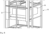
- FIG. 3 is an enlarged perspective view of an accommodation space 21 portion of one charge/discharge box 30 in FIG. 2
- FIG. 4 is a side view thereof.
- the wiring duct 22 is provided at one side of the accommodation space 21 provided in the accommodation structure 20, and a wire bundle made up of a plurality of wires 23 for supplying electricity to the charge/discharge box passes through the empty space of the wiring duct 22, and an exhaust fan 24 is installed at the external side of the wiring so as to discharge heat generated during charge/discharge from the charge/discharge box to the outside.
- the performance of the lithium secondary battery may vary greatly depending on the temperature, and the activation process of the secondary battery is simultaneously performed by placing a plurality of charge/discharge boxes in layers in the process chamber and accommodating a plurality of battery cells in another charge/discharge box. As such, since there may be a temperature deviation between the charge/discharge boxes or between various battery cells in the charge/discharge box, it is important to maintain a uniform temperature distribution.
- the accommodation space 21 of the charge/discharge box 30 is open, so that external heat generation, temperature deviation, and the like are affected internally, and temperature variations occur between charge/discharge boxes according to such external influences.
- the charge/discharge process of the secondary battery in addition to the heat generated in the battery cell, a considerable amount of heat is generated in the wiring itself for supplying power to the plurality of charge/discharge boxes.
- the wiring is made inside the wiring duct 22 which contacts the accommodation space 21 of the charge/discharge box 30, and an exhaust fan 24 of the wiring duct 22 is installed outside the wiring to suck air in the wiring duct 22 to induce air flow to the outside of the charger/discharger.
- the heat generated from the electric wire 23 was not discharged to the outside by the exhaust fan 24 smoothly, thereby lowering the heat discharge efficiency.
- the temperature inside the wiring duct 22 increases due to the heat generated by the wires arranged, and the temperature inside the wiring duct 22 affects the adjacent charge/discharge box 30.
- there has been a problem that a temperature deviation occurs and due to such a temperature deviation, a battery capacity or the like has been incorrectly measured or a measurement deviation has occurred, thereby lowering the reliability of the measurement.
- the present invention is to solve the problems of the prior art as described above, and an object of the present invention is to provide a charge/discharge device for the activation process of a secondary battery that can uniformly control the internal temperature by preventing heat generated by wiring, etc. from affecting the inside of the charge/discharge box when the activation process is performed after manufacturing the secondary battery.
- a charge/discharge device for an activation process of a secondary battery includes an accommodation structure having a plurality of accommodation spaces and provided with a wiring duct at one side of each of the accommodation spaces, each of a plurality of charge/discharge boxes installed in each of the plurality of accommodation spaces, wires wired in a space inside the wiring duct, and an exhaust fan installed on an inner wall of the wiring duct
- the exhaust fan is installed on the inner wall of the wiring duct adjacent to one side of the accommodation space, and the wires are wired to pass an external side of the exhaust fan.
- a heat insulation panel may be additionally installed together with the exhaust fan in the wiring duct.
- the internal temperature may be uniformly controlled by allowing the heat generated by the wiring, etc. at the time of performing the activation process of the secondary battery not to influence the inside of the charge/discharge box.
- the exhaust fan blows wind from the inner wall of the wiring duct provided with the exhaust fan in the direction of the inner wall of the other wiring duct facing it, blows directly to the electric wire that generates heat, and forcibly circulates the air inside the wiring duct to thereby be discharged.
- cooling efficiency is very excellent.
- an exhaust port may be further provided on the inner wall of the other wiring duct facing the inner wall of the wiring duct on which the exhaust fan is installed.
- the exhaust fan may be provided in plurality, and the cooling efficiency may be further increased by a method of arranging the exhaust fans to be spaced apart from each other along the length direction or the width direction of the inner wall of the wiring duct.
- the secondary battery charging and discharging device may further include a heat insulation panel on the inner wall of the wiring duct, and the insulation panel prevents heat generated from the wiring from moving to the charge/discharge box, thereby improving temperature variation, which is an effect of the present invention.
- the heat insulation panel is preferably installed on the inner wall of the wiring duct adjacent to one side of the accommodation space in which the charge/discharge box is accommodated.
- the exhaust fan when the exhaust fan and the heat insulation panel are installed together, the exhaust fan may be installed on the upper portion of the heat insulation panel, and may form a through-hole penetrating through the heat insulation panel and the inner wall of the wiring duct together, and then may be inserted into and installed in the through-hole.
- the cooling efficiency inside the wiring duct can be increased intensively.
- the through-hole is formed in the inner wall of the heat insulation panel and the wiring duct, and the exhaust fan is inserted into the formed through-hole, the heat generated from the charge/discharge box as well as the heat generated from the wiring are absorbed and discharged together.
- the charge/discharge device of a secondary battery according to the present invention is electrically connected and operated by charge/discharge boxes and exhaust fan wired wires, and each charge/discharge box is accommodated in an accommodation structure having an accommodation space of the charge/discharge box.
- the accommodation structure is preferably a structure having a plurality of accommodation spaces for accommodating a plurality of charge/discharge boxes stacked in both horizontal and vertical directions to allow mass production of secondary batteries.
- the temperature deviation between the charge/discharge boxes can be significantly reduced, thereby improving the process deviation of the capacity and resistance which are very sensitive to temperature.
- the effect on the internal charge/discharge box is significantly reduced, and the process deviation problem is improved, and when a heat insulation panel is additionally installed, the external temperature difference may be blocked by the heat insulation panel, thereby further reducing the temperature variation. Accordingly, since the temperature rise and the temperature deviation in the charge/discharge box are prevented or minimized, there is an effect that can solve the problem that the battery capacity is incorrectly measured or measurement deviation occurs.
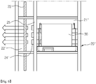
- FIG. 5 is a perspective view illustrating one charge/discharge box part as one embodiment of a charge/discharge device according to the present invention
- FIG. 6 is a side view thereof.
- the charge/discharge device of the present invention includes an accommodation structure 20' for accommodating and arranging a plurality of charge/discharge boxes.
- the accommodation structure 20' is provided with a plurality of accommodation spaces 21' to accommodate and install the charge/discharge boxes 30 therein.
- a wiring duct 22' is provided at one side of each of the accommodation spaces 21', and many wires 23' are wired to supply electricity to the charge/discharge boxes 30.
- an exhaust fan 24' is provided to discharge heat generated during charging and discharging to the outside.
- the accommodation structure 20' has a structure including a plurality of accommodation spaces 21' so as to accommodate a plurality of charge/discharge boxes 30 stacked in both horizontal and vertical directions, to thereby respond suitably to the mass production of secondary batteries.
- an exhaust fan 24' is mounted on the inner wall 25, and a plurality of exhaust fans may be disposed in a state spaced apart from each other along a length direction or a width direction of the inner wall 25 of the wiring duct ( FIG. 5 shows some of the plurality of exhaust fans that can be installed).
- a heat insulation panel 26 may be additionally installed on the inner wall 25 of the wiring duct 22'.
- the heat insulation panel when the secondary battery is activated, heat generated by wiring or the like and an external temperature difference can be prevented from affecting the inside of the charge/discharge box, thereby controlling the temperature inside the charge/discharge box to be uniform.
- an exhaust fan may be installed on the heat insulation panel, and according to another embodiment of the present invention (see FIG. 8 ), after forming a through-hole penetrating the heat insulation panel and the inner wall 25 together, the exhaust fan may be inserted into the formed through-hole to be installed.
- the cooling efficiency of the inside of the wiring duct 22' can be increased intensively. Further, in the case where the through-hole is formed and the exhaust fan is inserted into the inner wall 25, it is preferable in that heat generated from the charge/discharge box 30 can be absorbed and discharged.
- the electric wire 23' for supplying electricity to the charge/discharge box 30 is arranged in the wiring duct 22', but is wired outside the exhaust fan 24'.
- the structure of such a device makes it possible to efficiently discharge heat by directly blowing wind generated by the exhaust fan from the electric wires 23' generating heat.
- the heat insulation panel can be used without particular limitation as long as it can be installed on the inner wall 25 of the wiring duct and can allow the exhaust fan 24' to be installed and supported. Further, since any appropriate material among those known to one of ordinary skill in the art can be used as a material of such a heat insulation panel, a detailed description thereof will be omitted here.
- FIG. 9 is a perspective view schematically showing an example of a charge/discharge box that can be used in a charge/discharge device according to the present invention.
- the charge/discharge box 30 has a form in which charge/discharge terminals 32 are provided on the left and right sidewalls of a box-shaped body 31, and these charge/discharge terminals 32 are configured to be able to contact the electrode leads of a plurality of battery cells mounted in a battery tray (not shown) to apply electric current.
- a blowing fan 33 may be installed at the ceiling of the body to cool the heat generated during the activation process.
- the box-shaped body has a structure in which at least one side of the four sides is open, and the tray is put into the inside or discharged by a stacker crane (not shown) through the opening.
- a battery tray is used to easily and safely handle a plurality of battery cells, and a plurality of battery cells are stored therein and are put into the charge/discharge box to perform a charge/discharge process.
- the battery tray can be properly selected and used by those skilled in the art from those known in the art, a detailed description thereof is also omitted here.
- the charge/discharge device does not affect the inside of the charge/discharge box by heat generation due to wiring or the like, external temperature difference, etc. when the secondary battery is activated. Further, the charge/discharge device can allow the heat generated from the wires connected to the wiring duct to be smoothly discharged to the outside, thereby preventing or minimizing the temperature rise and temperature variation in the charge/discharge box, which is very useful industrially.
Landscapes
- Engineering & Computer Science (AREA)
- Manufacturing & Machinery (AREA)
- Chemical & Material Sciences (AREA)
- Chemical Kinetics & Catalysis (AREA)
- Electrochemistry (AREA)
- General Chemical & Material Sciences (AREA)
- Power Engineering (AREA)
- Secondary Cells (AREA)
- Battery Mounting, Suspending (AREA)
Abstract
Description
- This application claims the benefit of priority based on Korean Patent Application No.
10-2018-0027427, filed on March 8, 2018 - The present invention relates to a charge/discharge device for an activation process of a secondary battery, and more particularly, to a charge/discharge device for an activation process of a secondary battery capable of controlling the internal temperature of a charge/discharge box to be uniform by not allowing the external heat generation and temperature difference, at the time of performing the activation process after manufacturing a secondary battery, to influence the inside of the charge/discharge box.
- As technology development and demand for mobile devices are increasing and the spread of electric vehicles is expanding, demand for secondary batteries as energy sources is rapidly increasing. Among them, demand for lithium secondary batteries having high capacity and energy density is especially high.
- In general, a lithium secondary battery is manufactured by containing in an electrode assembly consisting of a negative electrode, a positive electrode, and a separator into a pouch-shaped case of a cylindrical or rectangular metal can or an aluminum laminate sheet, and injecting electrolyte into the electrode assembly. The lithium secondary battery manufactured as described above can function as a battery only by activating the battery by performing a predetermined charge/discharge. Such a process is called a formation process or an activation process. In this activation process, a charge/discharge device is used. In the mass production process of secondary batteries, the charge/discharge device is generally set to be capable of simultaneously charging and discharging a plurality of cells in order to increase productivity.
-
FIG. 1 is a plan view schematically showing an example of an arrangement state of a conventional charge/discharge device for performing a large amount of activation processes of a secondary battery, andFIG. 2 is a side view of a part thereof. Referring to these drawings, anaccommodation structure 20, in which the plurality ofaccommodation spaces 21 and thewiring duct 22 are provided so that a plurality of charge/discharge boxes can be piled up in the horizontal direction and the vertical direction, is arranged in anactivation process chamber 10. And each of theaccommodation spaces 21 is provided with a charge/discharge box 30. -
FIG. 3 is an enlarged perspective view of anaccommodation space 21 portion of one charge/discharge box 30 inFIG. 2 , andFIG. 4 is a side view thereof. Referring to these drawings, thewiring duct 22 is provided at one side of theaccommodation space 21 provided in theaccommodation structure 20, and a wire bundle made up of a plurality ofwires 23 for supplying electricity to the charge/discharge box passes through the empty space of thewiring duct 22, and anexhaust fan 24 is installed at the external side of the wiring so as to discharge heat generated during charge/discharge from the charge/discharge box to the outside. - The performance of the lithium secondary battery may vary greatly depending on the temperature, and the activation process of the secondary battery is simultaneously performed by placing a plurality of charge/discharge boxes in layers in the process chamber and accommodating a plurality of battery cells in another charge/discharge box. As such, since there may be a temperature deviation between the charge/discharge boxes or between various battery cells in the charge/discharge box, it is important to maintain a uniform temperature distribution.
- However, in the conventional charge/discharge device, as shown in
FIGS. 3 and4 , theaccommodation space 21 of the charge/discharge box 30 is open, so that external heat generation, temperature deviation, and the like are affected internally, and temperature variations occur between charge/discharge boxes according to such external influences. In addition, in the charge/discharge process of the secondary battery, in addition to the heat generated in the battery cell, a considerable amount of heat is generated in the wiring itself for supplying power to the plurality of charge/discharge boxes. Referring to the structure of a conventional charge/discharge device, the wiring is made inside thewiring duct 22 which contacts theaccommodation space 21 of the charge/discharge box 30, and anexhaust fan 24 of thewiring duct 22 is installed outside the wiring to suck air in thewiring duct 22 to induce air flow to the outside of the charger/discharger. As such, the heat generated from theelectric wire 23 was not discharged to the outside by theexhaust fan 24 smoothly, thereby lowering the heat discharge efficiency. As a result, the temperature inside thewiring duct 22 increases due to the heat generated by the wires arranged, and the temperature inside thewiring duct 22 affects the adjacent charge/discharge box 30. As such, there has been a problem that a temperature deviation occurs, and due to such a temperature deviation, a battery capacity or the like has been incorrectly measured or a measurement deviation has occurred, thereby lowering the reliability of the measurement. - Accordingly, the present invention is to solve the problems of the prior art as described above, and an object of the present invention is to provide a charge/discharge device for the activation process of a secondary battery that can uniformly control the internal temperature by preventing heat generated by wiring, etc. from affecting the inside of the charge/discharge box when the activation process is performed after manufacturing the secondary battery.
- A charge/discharge device for an activation process of a secondary battery according to the present invention includes an accommodation structure having a plurality of accommodation spaces and provided with a wiring duct at one side of each of the accommodation spaces, each of a plurality of charge/discharge boxes installed in each of the plurality of accommodation spaces, wires wired in a space inside the wiring duct, and an exhaust fan installed on an inner wall of the wiring duct
- Herein, the exhaust fan is installed on the inner wall of the wiring duct adjacent to one side of the accommodation space, and the wires are wired to pass an external side of the exhaust fan.
- Further, a heat insulation panel may be additionally installed together with the exhaust fan in the wiring duct. Through this configuration, the internal temperature may be uniformly controlled by allowing the heat generated by the wiring, etc. at the time of performing the activation process of the secondary battery not to influence the inside of the charge/discharge box.
- On the other hand, the exhaust fan blows wind from the inner wall of the wiring duct provided with the exhaust fan in the direction of the inner wall of the other wiring duct facing it, blows directly to the electric wire that generates heat, and forcibly circulates the air inside the wiring duct to thereby be discharged. Hence, cooling efficiency is very excellent.
- In addition, in order to further increase the cooling efficiency, an exhaust port may be further provided on the inner wall of the other wiring duct facing the inner wall of the wiring duct on which the exhaust fan is installed.
- The exhaust fan may be provided in plurality, and the cooling efficiency may be further increased by a method of arranging the exhaust fans to be spaced apart from each other along the length direction or the width direction of the inner wall of the wiring duct.
- The secondary battery charging and discharging device may further include a heat insulation panel on the inner wall of the wiring duct, and the insulation panel prevents heat generated from the wiring from moving to the charge/discharge box, thereby improving temperature variation, which is an effect of the present invention. In order to block heat flowing into the charge/discharge box from the wiring, the heat insulation panel is preferably installed on the inner wall of the wiring duct adjacent to one side of the accommodation space in which the charge/discharge box is accommodated. In addition, when the exhaust fan and the heat insulation panel are installed together, the exhaust fan may be installed on the upper portion of the heat insulation panel, and may form a through-hole penetrating through the heat insulation panel and the inner wall of the wiring duct together, and then may be inserted into and installed in the through-hole.
- When the exhaust fan is installed on the heat insulation panel, there is an advantage that the cooling efficiency inside the wiring duct can be increased intensively. When the through-hole is formed in the inner wall of the heat insulation panel and the wiring duct, and the exhaust fan is inserted into the formed through-hole, the heat generated from the charge/discharge box as well as the heat generated from the wiring are absorbed and discharged together.
- The charge/discharge device of a secondary battery according to the present invention is electrically connected and operated by charge/discharge boxes and exhaust fan wired wires, and each charge/discharge box is accommodated in an accommodation structure having an accommodation space of the charge/discharge box.
- The accommodation structure is preferably a structure having a plurality of accommodation spaces for accommodating a plurality of charge/discharge boxes stacked in both horizontal and vertical directions to allow mass production of secondary batteries.
- Further, when the secondary battery is activated by the charge/discharge device according to the present invention, the temperature deviation between the charge/discharge boxes can be significantly reduced, thereby improving the process deviation of the capacity and resistance which are very sensitive to temperature.
- According to the present invention, as the heat generated from the wires wired in the wiring duct to perform the activation process of the secondary battery is smoothly discharged to the outside by the exhaust fan, the effect on the internal charge/discharge box is significantly reduced, and the process deviation problem is improved, and when a heat insulation panel is additionally installed, the external temperature difference may be blocked by the heat insulation panel, thereby further reducing the temperature variation. Accordingly, since the temperature rise and the temperature deviation in the charge/discharge box are prevented or minimized, there is an effect that can solve the problem that the battery capacity is incorrectly measured or measurement deviation occurs.
-
-
FIG. 1 is a plan view schematically showing an example of an arrangement state of a conventional charge/discharge device for performing a large amount of activation processes of a secondary battery, andFIG. 2 is a side view of a part thereof. -
FIG. 3 is an enlarged perspective view of an accommodation space portion of one charge/discharge box inFIG. 2 , andFIG. 4 is a side view thereof. -
FIG. 5 is a perspective view illustrating one charge/discharge box part as one embodiment of a charge/discharge device according to the present invention, andFIG. 6 is a side view thereof. -
FIG. 7 is a side view of an embodiment of a charge/discharge device according to the present invention, in which a heat insulation panel is installed on an inner wall of a wiring duct of the charge/discharge device, and an exhaust fan is installed thereon. -
FIG. 8 is a side view of an embodiment of a charge/discharge device according to the present invention, in which an insulation panel is installed on an inner wall of a wiring duct of the charge/discharge device, and an exhaust fan is inserted through an inner wall of the wiring duct and a heat insulation panel. -
FIG. 9 is a perspective view showing an example of a charge/discharge box of a charge/discharge device according to the present invention. - Hereinafter, the present invention will be described more specifically with reference to the accompanying drawings about exemplary embodiments of the present invention. It is to be understood that the following detailed description and drawings are merely illustrative of the embodiments of the present invention, and therefore the present invention should not be construed as being limited to the description and contents.
- Meanwhile, in the present invention, terms indicating direction, such as 'upper' and 'lower' are used, but these terms are used on the basis of the drawings shown for ease of explanation and easy understanding. It is to be understood that they are used in the sense of relative relationship and not in the sense of absolute relationship, and these terms should not be unduly construed to limit the scope of the present invention.
-
FIG. 5 is a perspective view illustrating one charge/discharge box part as one embodiment of a charge/discharge device according to the present invention, andFIG. 6 is a side view thereof. Referring to these drawings, the charge/discharge device of the present invention includes an accommodation structure 20' for accommodating and arranging a plurality of charge/discharge boxes. The accommodation structure 20' is provided with a plurality of accommodation spaces 21' to accommodate and install the charge/discharge boxes 30 therein. A wiring duct 22' is provided at one side of each of the accommodation spaces 21', and many wires 23' are wired to supply electricity to the charge/discharge boxes 30. Further, an exhaust fan 24' is provided to discharge heat generated during charging and discharging to the outside. - The accommodation structure 20' has a structure including a plurality of accommodation spaces 21' so as to accommodate a plurality of charge/
discharge boxes 30 stacked in both horizontal and vertical directions, to thereby respond suitably to the mass production of secondary batteries. - In addition, an exhaust fan 24' is mounted on the
inner wall 25, and a plurality of exhaust fans may be disposed in a state spaced apart from each other along a length direction or a width direction of theinner wall 25 of the wiring duct (FIG. 5 shows some of the plurality of exhaust fans that can be installed). - Meanwhile, in the charge/discharge device of the present invention, a
heat insulation panel 26 may be additionally installed on theinner wall 25 of the wiring duct 22'. By the heat insulation panel, when the secondary battery is activated, heat generated by wiring or the like and an external temperature difference can be prevented from affecting the inside of the charge/discharge box, thereby controlling the temperature inside the charge/discharge box to be uniform. - When the insulation panel is additionally installed on the
inner wall 25, according to an embodiment of the present invention (seeFIG. 7 ), an exhaust fan may be installed on the heat insulation panel, and according to another embodiment of the present invention (seeFIG. 8 ), after forming a through-hole penetrating the heat insulation panel and theinner wall 25 together, the exhaust fan may be inserted into the formed through-hole to be installed. - When the exhaust fan is installed on the heat insulation panel, the cooling efficiency of the inside of the wiring duct 22' can be increased intensively. Further, in the case where the through-hole is formed and the exhaust fan is inserted into the
inner wall 25, it is preferable in that heat generated from the charge/discharge box 30 can be absorbed and discharged. - On the other hand, the electric wire 23' for supplying electricity to the charge/
discharge box 30 is arranged in the wiring duct 22', but is wired outside the exhaust fan 24'. The structure of such a device makes it possible to efficiently discharge heat by directly blowing wind generated by the exhaust fan from the electric wires 23' generating heat. - The heat insulation panel can be used without particular limitation as long as it can be installed on the
inner wall 25 of the wiring duct and can allow the exhaust fan 24' to be installed and supported. Further, since any appropriate material among those known to one of ordinary skill in the art can be used as a material of such a heat insulation panel, a detailed description thereof will be omitted here. - Any change/discharge box known to one of ordinary skill in the art may be used as the charge/
discharge box 30 in the present invention.FIG. 9 is a perspective view schematically showing an example of a charge/discharge box that can be used in a charge/discharge device according to the present invention. Referring toFIG. 9 , the charge/discharge box 30 has a form in which charge/discharge terminals 32 are provided on the left and right sidewalls of a box-shapedbody 31, and these charge/discharge terminals 32 are configured to be able to contact the electrode leads of a plurality of battery cells mounted in a battery tray (not shown) to apply electric current. Meanwhile, a blowingfan 33 may be installed at the ceiling of the body to cool the heat generated during the activation process. The box-shaped body has a structure in which at least one side of the four sides is open, and the tray is put into the inside or discharged by a stacker crane (not shown) through the opening. - In the charge/discharge box of the present invention, a battery tray is used to easily and safely handle a plurality of battery cells, and a plurality of battery cells are stored therein and are put into the charge/discharge box to perform a charge/discharge process. As the battery tray can be properly selected and used by those skilled in the art from those known in the art, a detailed description thereof is also omitted here.
- As described above in detail, the charge/discharge device according to the present invention does not affect the inside of the charge/discharge box by heat generation due to wiring or the like, external temperature difference, etc. when the secondary battery is activated. Further, the charge/discharge device can allow the heat generated from the wires connected to the wiring duct to be smoothly discharged to the outside, thereby preventing or minimizing the temperature rise and temperature variation in the charge/discharge box, which is very useful industrially.
- While the present invention has been particularly shown and described with reference to exemplary embodiments thereof, it is to be understood that the invention is not to be limited to the details thereof, and it will be apparent to those skilled in the art that various modifications such as the above description, substitutions of components and the like, addition of additional components, and the like may be made without departing from the scope of the present invention based on the above description.
-
- 10: activation process chamber
- 20, 20': accommodation structure
- 21, 21': accommodation space
- 22, 22': wiring duct
- 23, 23': wire
- 24, 24': exhaust fan
- 25: inner wall of wiring duct
- 26: heat insulation panel
- 30: charge/discharge box
- 31: body
- 32: charge/discharge terminal
- 33: blowing fan
Claims (10)
- A charge/discharge device for an activation process of a secondary battery, the charge/discharge device comprising:an accommodation structure having a plurality of accommodation spaces and provided with a wiring duct at one side of each of the accommodation spaces;each of a plurality of charge/discharge boxes installed in each of the plurality of accommodation spaces;wires wired in a space inside the wiring duct; andan exhaust fan installed on an inner wall of the wiring duct,wherein the exhaust fan is installed on the inner wall of the wiring duct adjacent to one side of the accommodation space, andwherein the wires are wired to pass an external side of the exhaust fan.
- The charge/discharge device of claim 1, wherein an exhaust port blows air from the inner wall of the wiring duct provided with the exhaust fan in a direction of the inner wall of the other wiring duct facing the exhaust fan.
- The charge/discharge device of claim 1, wherein an exhaust port is additionally installed on the inner wall of the other wiring duct facing the inner wall of the wiring duct in which the exhaust fan is installed.
- The charge/discharge of claim 1, wherein the exhaust fan is provided in plurality to thereby be arranged to be spaced apart from each other along a longitudinal direction or a width direction of the inner wall of the wiring duct.
- The charge/discharge device of claim 1, wherein the charge/discharge device of the secondary battery further includes a heat insulation panel installed on the inner wall of the wiring duct.
- The charge/discharge device of claim 5, wherein the heat insulation panel is installed on the inner wall of the wiring duct adjacent to one side of the accommodation space, and
wherein the exhaust fan is installed on the heat insulation panel. - The charge/discharge device of claim 5, wherein the heat insulation panel is installed on the inner wall of the wiring duct adjacent to one side of the accommodation space,
wherein at least one through-hole, which penetrates the heat insulation panel and the inner wall of the wiring duct at which the heat insulation panel in installed, is formed, and
wherein the exhaust fan is inserted into the through-hole. - The charge/discharge box of claim 1, wherein the plurality of charge and discharge boxes and the exhaust fan are electrically connected by the wires.
- The charge/discharge device of claim 1, further comprising a plurality of accommodation spaces for accommodating a plurality of charge/discharge boxes such that the charge/discharge boxes are stacked in both horizontal and vertical directions.
- A secondary battery activation method for charging/discharging for secondary battery activation using the charge/discharge device of the secondary battery according to claim 1.
Applications Claiming Priority (2)
| Application Number | Priority Date | Filing Date | Title |
|---|---|---|---|
| KR1020180027427A KR102351291B1 (en) | 2018-03-08 | 2018-03-08 | Charging-Recharging Equipment for Activation Process of Secondary Battery with Improved Temperature Deviation |
| PCT/KR2019/000122 WO2019172515A1 (en) | 2018-03-08 | 2019-01-04 | Charging/discharging device, having reduced temperature difference, for secondary battery formation process |
Publications (3)
| Publication Number | Publication Date |
|---|---|
| EP3644411A1 true EP3644411A1 (en) | 2020-04-29 |
| EP3644411A4 EP3644411A4 (en) | 2020-12-23 |
| EP3644411B1 EP3644411B1 (en) | 2023-03-01 |
Family
ID=67846725
Family Applications (1)
| Application Number | Title | Priority Date | Filing Date |
|---|---|---|---|
| EP19765079.9A Active EP3644411B1 (en) | 2018-03-08 | 2019-01-04 | Charging/discharging device, having reduced temperature difference, for secondary battery formation process |
Country Status (6)
| Country | Link |
|---|---|
| US (1) | US11621445B2 (en) |
| EP (1) | EP3644411B1 (en) |
| KR (1) | KR102351291B1 (en) |
| CN (1) | CN110915029B (en) |
| PL (1) | PL3644411T3 (en) |
| WO (1) | WO2019172515A1 (en) |
Cited By (1)
| Publication number | Priority date | Publication date | Assignee | Title |
|---|---|---|---|---|
| EP4250521A4 (en) * | 2021-11-19 | 2024-07-10 | LG Energy Solution, Ltd. | BATTERY CELL CHARGING AND DISCHARGE DEVICE INCLUDING LOWER FANS |
Families Citing this family (2)
| Publication number | Priority date | Publication date | Assignee | Title |
|---|---|---|---|---|
| CN113270928A (en) * | 2021-06-18 | 2021-08-17 | 新乡北方车辆仪表有限公司 | Multifunctional clamp type low-temperature charging device |
| KR102498020B1 (en) | 2022-07-18 | 2023-02-08 | 류남용 | fireproof screen for formation apparatus of secondary battery |
Family Cites Families (19)
| Publication number | Priority date | Publication date | Assignee | Title |
|---|---|---|---|---|
| KR19980075556A (en) * | 1997-03-31 | 1998-11-16 | 손욱 | Cooling device for charge / discharge facility of storage battery |
| JP2004179009A (en) * | 2002-11-27 | 2004-06-24 | Sony Corp | Battery aging method and aging device |
| US8084154B2 (en) * | 2007-02-08 | 2011-12-27 | Karl Frederick Scheucher | Battery pack safety and thermal management apparatus and method |
| JP5127426B2 (en) | 2007-12-18 | 2013-01-23 | トヨタ自動車株式会社 | Electric vehicle charging system |
| KR101051446B1 (en) | 2009-07-07 | 2011-07-22 | 주식회사 프로파워 | Battery case |
| JP5765061B2 (en) | 2011-06-03 | 2015-08-19 | 株式会社Ihi | Combined battery cell combination system |
| JP5558504B2 (en) * | 2012-02-13 | 2014-07-23 | エスペック株式会社 | Charge / discharge test apparatus and manufacturing method thereof |
| JP2013168214A (en) * | 2012-02-14 | 2013-08-29 | Hitachi Ltd | Battery module |
| KR101319862B1 (en) | 2012-06-07 | 2013-10-18 | 주식회사 피앤이솔루션 | Charge and discharge system for battery |
| KR101371739B1 (en) | 2012-09-07 | 2014-03-12 | 기아자동차(주) | Battery system |
| KR101606961B1 (en) * | 2013-08-30 | 2016-03-28 | 주식회사 엘지화학 | Device for charge and discharge of secondary battery and activation method of secondary battery using the same |
| KR101625716B1 (en) | 2013-09-27 | 2016-05-30 | 주식회사 엘지화학 | Device for charge and discharge og secondary battery |
| KR101760402B1 (en) | 2015-01-05 | 2017-07-21 | 주식회사 엘지화학 | Battery module and battery pack including the same |
| KR101760403B1 (en) * | 2015-01-05 | 2017-07-31 | 주식회사 엘지화학 | Battery module and battery pack including the same |
| JP6463974B2 (en) | 2015-01-16 | 2019-02-06 | 株式会社Subaru | Automotive battery |
| KR101779187B1 (en) | 2015-04-23 | 2017-09-18 | 주식회사 뉴피에스 | Enhanced safety battery storage |
| CN107848681B (en) | 2015-07-09 | 2022-07-05 | 蒙诺苏尔有限公司 | Food product and method of making the same |
| KR102089264B1 (en) * | 2016-02-25 | 2020-03-16 | 주식회사 엘지화학 | Device for Charge and Discharge of Secondary Battery |
| KR101816843B1 (en) * | 2016-12-19 | 2018-01-09 | (주)에이프로 | Cooling Device for Battery Charge/Discharge Device |
-
2018
- 2018-03-08 KR KR1020180027427A patent/KR102351291B1/en active Active
-
2019
- 2019-01-04 PL PL19765079.9T patent/PL3644411T3/en unknown
- 2019-01-04 EP EP19765079.9A patent/EP3644411B1/en active Active
- 2019-01-04 US US16/633,498 patent/US11621445B2/en active Active
- 2019-01-04 CN CN201980003556.7A patent/CN110915029B/en active Active
- 2019-01-04 WO PCT/KR2019/000122 patent/WO2019172515A1/en not_active Ceased
Cited By (1)
| Publication number | Priority date | Publication date | Assignee | Title |
|---|---|---|---|---|
| EP4250521A4 (en) * | 2021-11-19 | 2024-07-10 | LG Energy Solution, Ltd. | BATTERY CELL CHARGING AND DISCHARGE DEVICE INCLUDING LOWER FANS |
Also Published As
| Publication number | Publication date |
|---|---|
| US20210135299A1 (en) | 2021-05-06 |
| CN110915029B (en) | 2023-04-04 |
| KR20190106239A (en) | 2019-09-18 |
| CN110915029A (en) | 2020-03-24 |
| US11621445B2 (en) | 2023-04-04 |
| KR102351291B1 (en) | 2022-01-13 |
| PL3644411T3 (en) | 2023-05-08 |
| EP3644411B1 (en) | 2023-03-01 |
| EP3644411A4 (en) | 2020-12-23 |
| WO2019172515A1 (en) | 2019-09-12 |
Similar Documents
| Publication | Publication Date | Title |
|---|---|---|
| JP6296360B2 (en) | Battery unit | |
| WO2022134055A1 (en) | Battery box body, battery, electric device, and method and device for manufacturing box body | |
| CN109478621A (en) | Battery module, battery pack including the same, and vehicle including the battery pack | |
| CN219017811U (en) | Batteries and Electrical Devices | |
| EP3644411B1 (en) | Charging/discharging device, having reduced temperature difference, for secondary battery formation process | |
| KR101816843B1 (en) | Cooling Device for Battery Charge/Discharge Device | |
| JPWO2014068922A1 (en) | In-vehicle power supply device and vehicle equipped with power supply device | |
| CN116097499A (en) | Battery module, battery pack including the same, and vehicle | |
| KR20160015853A (en) | Lithium-air battery | |
| CN116802889B (en) | Battery, electric device, method and equipment for preparing battery | |
| KR102848029B1 (en) | Battery case body, battery, electrical equipment, battery manufacturing method and manufacturing equipment | |
| EP4152485A1 (en) | Battery box, battery, electrical device, battery manufacturing method, and device | |
| CN210956793U (en) | Battery pack with low-temperature heating function and communication standby power system | |
| KR20140081940A (en) | Battery Module Assembly | |
| KR20060064854A (en) | Battery case for thermal control and battery pack structure using the same | |
| US20240282999A1 (en) | Battery tray and method for manufacturing battery using same | |
| KR101640886B1 (en) | Pack housing and battery pack including the same | |
| KR102724246B1 (en) | Long width secondary battery | |
| US12446183B2 (en) | Charge-and-discharge test apparatus and control method thereof | |
| EP4481917A1 (en) | Energy storage apparatus | |
| US20260081261A1 (en) | Battery pack | |
| EP4654365A1 (en) | Battery pack and vehicle including same | |
| KR20260058595A (en) | Apparatus for drying coated electrode and method for drying coated electrode using thereof | |
| KR20260027428A (en) | Precharger system for secondary battery | |
| CN120345120A (en) | Battery module, battery pack including the battery module, and vehicle |
Legal Events
| Date | Code | Title | Description |
|---|---|---|---|
| STAA | Information on the status of an ep patent application or granted ep patent |
Free format text: STATUS: THE INTERNATIONAL PUBLICATION HAS BEEN MADE |
|
| PUAI | Public reference made under article 153(3) epc to a published international application that has entered the european phase |
Free format text: ORIGINAL CODE: 0009012 |
|
| STAA | Information on the status of an ep patent application or granted ep patent |
Free format text: STATUS: REQUEST FOR EXAMINATION WAS MADE |
|
| 17P | Request for examination filed |
Effective date: 20200124 |
|
| AK | Designated contracting states |
Kind code of ref document: A1 Designated state(s): AL AT BE BG CH CY CZ DE DK EE ES FI FR GB GR HR HU IE IS IT LI LT LU LV MC MK MT NL NO PL PT RO RS SE SI SK SM TR |
|
| AX | Request for extension of the european patent |
Extension state: BA ME |
|
| A4 | Supplementary search report drawn up and despatched |
Effective date: 20201120 |
|
| RIC1 | Information provided on ipc code assigned before grant |
Ipc: H01M 10/052 20100101ALN20201116BHEP Ipc: H01M 10/617 20140101ALI20201116BHEP Ipc: H01M 4/04 20060101AFI20201116BHEP Ipc: H02J 7/00 20060101ALI20201116BHEP Ipc: H01M 10/04 20060101ALI20201116BHEP Ipc: H01M 10/613 20140101ALI20201116BHEP Ipc: H01M 10/658 20140101ALI20201116BHEP Ipc: H01M 10/6563 20140101ALI20201116BHEP Ipc: H01M 10/058 20100101ALN20201116BHEP Ipc: H01M 10/44 20060101ALI20201116BHEP |
|
| DAV | Request for validation of the european patent (deleted) | ||
| DAX | Request for extension of the european patent (deleted) | ||
| RAP1 | Party data changed (applicant data changed or rights of an application transferred) |
Owner name: LG ENERGY SOLUTION LTD. |
|
| RAP3 | Party data changed (applicant data changed or rights of an application transferred) |
Owner name: LG ENERGY SOLUTION, LTD. |
|
| GRAP | Despatch of communication of intention to grant a patent |
Free format text: ORIGINAL CODE: EPIDOSNIGR1 |
|
| STAA | Information on the status of an ep patent application or granted ep patent |
Free format text: STATUS: GRANT OF PATENT IS INTENDED |
|
| RIC1 | Information provided on ipc code assigned before grant |
Ipc: H01M 10/058 20100101ALN20221026BHEP Ipc: H01M 10/052 20100101ALN20221026BHEP Ipc: H01M 10/658 20140101ALI20221026BHEP Ipc: H01M 10/6563 20140101ALI20221026BHEP Ipc: H01M 10/617 20140101ALI20221026BHEP Ipc: H01M 10/613 20140101ALI20221026BHEP Ipc: H01M 10/04 20060101ALI20221026BHEP Ipc: H01M 10/44 20060101ALI20221026BHEP Ipc: H02J 7/00 20060101ALI20221026BHEP Ipc: H01M 4/04 20060101AFI20221026BHEP |
|
| INTG | Intention to grant announced |
Effective date: 20221115 |
|
| GRAS | Grant fee paid |
Free format text: ORIGINAL CODE: EPIDOSNIGR3 |
|
| GRAA | (expected) grant |
Free format text: ORIGINAL CODE: 0009210 |
|
| STAA | Information on the status of an ep patent application or granted ep patent |
Free format text: STATUS: THE PATENT HAS BEEN GRANTED |
|
| AK | Designated contracting states |
Kind code of ref document: B1 Designated state(s): AL AT BE BG CH CY CZ DE DK EE ES FI FR GB GR HR HU IE IS IT LI LT LU LV MC MK MT NL NO PL PT RO RS SE SI SK SM TR |
|
| REG | Reference to a national code |
Ref country code: GB Ref legal event code: FG4D |
|
| REG | Reference to a national code |
Ref country code: CH Ref legal event code: EP Ref country code: AT Ref legal event code: REF Ref document number: 1551614 Country of ref document: AT Kind code of ref document: T Effective date: 20230315 |
|
| REG | Reference to a national code |
Ref country code: DE Ref legal event code: R096 Ref document number: 602019025892 Country of ref document: DE |
|
| REG | Reference to a national code |
Ref country code: IE Ref legal event code: FG4D |
|
| REG | Reference to a national code |
Ref country code: LT Ref legal event code: MG9D |
|
| P01 | Opt-out of the competence of the unified patent court (upc) registered |
Effective date: 20230525 |
|
| REG | Reference to a national code |
Ref country code: NL Ref legal event code: MP Effective date: 20230301 |
|
| PG25 | Lapsed in a contracting state [announced via postgrant information from national office to epo] |
Ref country code: RS Free format text: LAPSE BECAUSE OF FAILURE TO SUBMIT A TRANSLATION OF THE DESCRIPTION OR TO PAY THE FEE WITHIN THE PRESCRIBED TIME-LIMIT Effective date: 20230301 Ref country code: NO Free format text: LAPSE BECAUSE OF FAILURE TO SUBMIT A TRANSLATION OF THE DESCRIPTION OR TO PAY THE FEE WITHIN THE PRESCRIBED TIME-LIMIT Effective date: 20230601 Ref country code: LV Free format text: LAPSE BECAUSE OF FAILURE TO SUBMIT A TRANSLATION OF THE DESCRIPTION OR TO PAY THE FEE WITHIN THE PRESCRIBED TIME-LIMIT Effective date: 20230301 Ref country code: LT Free format text: LAPSE BECAUSE OF FAILURE TO SUBMIT A TRANSLATION OF THE DESCRIPTION OR TO PAY THE FEE WITHIN THE PRESCRIBED TIME-LIMIT Effective date: 20230301 Ref country code: HR Free format text: LAPSE BECAUSE OF FAILURE TO SUBMIT A TRANSLATION OF THE DESCRIPTION OR TO PAY THE FEE WITHIN THE PRESCRIBED TIME-LIMIT Effective date: 20230301 Ref country code: ES Free format text: LAPSE BECAUSE OF FAILURE TO SUBMIT A TRANSLATION OF THE DESCRIPTION OR TO PAY THE FEE WITHIN THE PRESCRIBED TIME-LIMIT Effective date: 20230301 |
|
| REG | Reference to a national code |
Ref country code: AT Ref legal event code: MK05 Ref document number: 1551614 Country of ref document: AT Kind code of ref document: T Effective date: 20230301 |
|
| PG25 | Lapsed in a contracting state [announced via postgrant information from national office to epo] |
Ref country code: SE Free format text: LAPSE BECAUSE OF FAILURE TO SUBMIT A TRANSLATION OF THE DESCRIPTION OR TO PAY THE FEE WITHIN THE PRESCRIBED TIME-LIMIT Effective date: 20230301 Ref country code: NL Free format text: LAPSE BECAUSE OF FAILURE TO SUBMIT A TRANSLATION OF THE DESCRIPTION OR TO PAY THE FEE WITHIN THE PRESCRIBED TIME-LIMIT Effective date: 20230301 Ref country code: GR Free format text: LAPSE BECAUSE OF FAILURE TO SUBMIT A TRANSLATION OF THE DESCRIPTION OR TO PAY THE FEE WITHIN THE PRESCRIBED TIME-LIMIT Effective date: 20230602 Ref country code: FI Free format text: LAPSE BECAUSE OF FAILURE TO SUBMIT A TRANSLATION OF THE DESCRIPTION OR TO PAY THE FEE WITHIN THE PRESCRIBED TIME-LIMIT Effective date: 20230301 |
|
| PG25 | Lapsed in a contracting state [announced via postgrant information from national office to epo] |
Ref country code: SM Free format text: LAPSE BECAUSE OF FAILURE TO SUBMIT A TRANSLATION OF THE DESCRIPTION OR TO PAY THE FEE WITHIN THE PRESCRIBED TIME-LIMIT Effective date: 20230301 Ref country code: RO Free format text: LAPSE BECAUSE OF FAILURE TO SUBMIT A TRANSLATION OF THE DESCRIPTION OR TO PAY THE FEE WITHIN THE PRESCRIBED TIME-LIMIT Effective date: 20230301 Ref country code: PT Free format text: LAPSE BECAUSE OF FAILURE TO SUBMIT A TRANSLATION OF THE DESCRIPTION OR TO PAY THE FEE WITHIN THE PRESCRIBED TIME-LIMIT Effective date: 20230703 Ref country code: EE Free format text: LAPSE BECAUSE OF FAILURE TO SUBMIT A TRANSLATION OF THE DESCRIPTION OR TO PAY THE FEE WITHIN THE PRESCRIBED TIME-LIMIT Effective date: 20230301 Ref country code: CZ Free format text: LAPSE BECAUSE OF FAILURE TO SUBMIT A TRANSLATION OF THE DESCRIPTION OR TO PAY THE FEE WITHIN THE PRESCRIBED TIME-LIMIT Effective date: 20230301 Ref country code: AT Free format text: LAPSE BECAUSE OF FAILURE TO SUBMIT A TRANSLATION OF THE DESCRIPTION OR TO PAY THE FEE WITHIN THE PRESCRIBED TIME-LIMIT Effective date: 20230301 |
|
| PG25 | Lapsed in a contracting state [announced via postgrant information from national office to epo] |
Ref country code: SK Free format text: LAPSE BECAUSE OF FAILURE TO SUBMIT A TRANSLATION OF THE DESCRIPTION OR TO PAY THE FEE WITHIN THE PRESCRIBED TIME-LIMIT Effective date: 20230301 Ref country code: IS Free format text: LAPSE BECAUSE OF FAILURE TO SUBMIT A TRANSLATION OF THE DESCRIPTION OR TO PAY THE FEE WITHIN THE PRESCRIBED TIME-LIMIT Effective date: 20230701 |
|
| REG | Reference to a national code |
Ref country code: DE Ref legal event code: R097 Ref document number: 602019025892 Country of ref document: DE |
|
| PLBE | No opposition filed within time limit |
Free format text: ORIGINAL CODE: 0009261 |
|
| STAA | Information on the status of an ep patent application or granted ep patent |
Free format text: STATUS: NO OPPOSITION FILED WITHIN TIME LIMIT |
|
| PG25 | Lapsed in a contracting state [announced via postgrant information from national office to epo] |
Ref country code: SI Free format text: LAPSE BECAUSE OF FAILURE TO SUBMIT A TRANSLATION OF THE DESCRIPTION OR TO PAY THE FEE WITHIN THE PRESCRIBED TIME-LIMIT Effective date: 20230301 Ref country code: DK Free format text: LAPSE BECAUSE OF FAILURE TO SUBMIT A TRANSLATION OF THE DESCRIPTION OR TO PAY THE FEE WITHIN THE PRESCRIBED TIME-LIMIT Effective date: 20230301 |
|
| 26N | No opposition filed |
Effective date: 20231204 |
|
| PG25 | Lapsed in a contracting state [announced via postgrant information from national office to epo] |
Ref country code: IT Free format text: LAPSE BECAUSE OF FAILURE TO SUBMIT A TRANSLATION OF THE DESCRIPTION OR TO PAY THE FEE WITHIN THE PRESCRIBED TIME-LIMIT Effective date: 20230301 |
|
| PG25 | Lapsed in a contracting state [announced via postgrant information from national office to epo] |
Ref country code: MC Free format text: LAPSE BECAUSE OF FAILURE TO SUBMIT A TRANSLATION OF THE DESCRIPTION OR TO PAY THE FEE WITHIN THE PRESCRIBED TIME-LIMIT Effective date: 20230301 |
|
| PG25 | Lapsed in a contracting state [announced via postgrant information from national office to epo] |
Ref country code: MC Free format text: LAPSE BECAUSE OF FAILURE TO SUBMIT A TRANSLATION OF THE DESCRIPTION OR TO PAY THE FEE WITHIN THE PRESCRIBED TIME-LIMIT Effective date: 20230301 |
|
| REG | Reference to a national code |
Ref country code: CH Ref legal event code: PL |
|
| PG25 | Lapsed in a contracting state [announced via postgrant information from national office to epo] |
Ref country code: LU Free format text: LAPSE BECAUSE OF NON-PAYMENT OF DUE FEES Effective date: 20240104 |
|
| PG25 | Lapsed in a contracting state [announced via postgrant information from national office to epo] |
Ref country code: LU Free format text: LAPSE BECAUSE OF NON-PAYMENT OF DUE FEES Effective date: 20240104 |
|
| PG25 | Lapsed in a contracting state [announced via postgrant information from national office to epo] |
Ref country code: BE Free format text: LAPSE BECAUSE OF NON-PAYMENT OF DUE FEES Effective date: 20240131 |
|
| PG25 | Lapsed in a contracting state [announced via postgrant information from national office to epo] |
Ref country code: CH Free format text: LAPSE BECAUSE OF NON-PAYMENT OF DUE FEES Effective date: 20240131 |
|
| PG25 | Lapsed in a contracting state [announced via postgrant information from national office to epo] |
Ref country code: CH Free format text: LAPSE BECAUSE OF NON-PAYMENT OF DUE FEES Effective date: 20240131 Ref country code: BE Free format text: LAPSE BECAUSE OF NON-PAYMENT OF DUE FEES Effective date: 20240131 |
|
| REG | Reference to a national code |
Ref country code: BE Ref legal event code: MM Effective date: 20240131 |
|
| PG25 | Lapsed in a contracting state [announced via postgrant information from national office to epo] |
Ref country code: BG Free format text: LAPSE BECAUSE OF FAILURE TO SUBMIT A TRANSLATION OF THE DESCRIPTION OR TO PAY THE FEE WITHIN THE PRESCRIBED TIME-LIMIT Effective date: 20230301 |
|
| PG25 | Lapsed in a contracting state [announced via postgrant information from national office to epo] |
Ref country code: BG Free format text: LAPSE BECAUSE OF FAILURE TO SUBMIT A TRANSLATION OF THE DESCRIPTION OR TO PAY THE FEE WITHIN THE PRESCRIBED TIME-LIMIT Effective date: 20230301 |
|
| PG25 | Lapsed in a contracting state [announced via postgrant information from national office to epo] |
Ref country code: IE Free format text: LAPSE BECAUSE OF NON-PAYMENT OF DUE FEES Effective date: 20240104 |
|
| PG25 | Lapsed in a contracting state [announced via postgrant information from national office to epo] |
Ref country code: IE Free format text: LAPSE BECAUSE OF NON-PAYMENT OF DUE FEES Effective date: 20240104 |
|
| PG25 | Lapsed in a contracting state [announced via postgrant information from national office to epo] |
Ref country code: CY Free format text: LAPSE BECAUSE OF FAILURE TO SUBMIT A TRANSLATION OF THE DESCRIPTION OR TO PAY THE FEE WITHIN THE PRESCRIBED TIME-LIMIT; INVALID AB INITIO Effective date: 20190104 |
|
| PG25 | Lapsed in a contracting state [announced via postgrant information from national office to epo] |
Ref country code: HU Free format text: LAPSE BECAUSE OF FAILURE TO SUBMIT A TRANSLATION OF THE DESCRIPTION OR TO PAY THE FEE WITHIN THE PRESCRIBED TIME-LIMIT; INVALID AB INITIO Effective date: 20190104 |
|
| PG25 | Lapsed in a contracting state [announced via postgrant information from national office to epo] |
Ref country code: TR Free format text: LAPSE BECAUSE OF FAILURE TO SUBMIT A TRANSLATION OF THE DESCRIPTION OR TO PAY THE FEE WITHIN THE PRESCRIBED TIME-LIMIT Effective date: 20230301 |
|
| PGFP | Annual fee paid to national office [announced via postgrant information from national office to epo] |
Ref country code: GB Payment date: 20251222 Year of fee payment: 8 |
|
| PGFP | Annual fee paid to national office [announced via postgrant information from national office to epo] |
Ref country code: FR Payment date: 20251223 Year of fee payment: 8 |
|
| PGFP | Annual fee paid to national office [announced via postgrant information from national office to epo] |
Ref country code: PL Payment date: 20251223 Year of fee payment: 8 |
|
| PGFP | Annual fee paid to national office [announced via postgrant information from national office to epo] |
Ref country code: DE Payment date: 20251222 Year of fee payment: 8 |