EP3644409B1 - Current interrupt device and battery module including same current interrupt device - Google Patents
Current interrupt device and battery module including same current interrupt device Download PDFInfo
- Publication number
- EP3644409B1 EP3644409B1 EP18904864.8A EP18904864A EP3644409B1 EP 3644409 B1 EP3644409 B1 EP 3644409B1 EP 18904864 A EP18904864 A EP 18904864A EP 3644409 B1 EP3644409 B1 EP 3644409B1
- Authority
- EP
- European Patent Office
- Prior art keywords
- connection part
- current interrupt
- interrupt device
- battery module
- battery
- Prior art date
- Legal status (The legal status is an assumption and is not a legal conclusion. Google has not performed a legal analysis and makes no representation as to the accuracy of the status listed.)
- Active
Links
Images




Classifications
-
- H—ELECTRICITY
- H01—ELECTRIC ELEMENTS
- H01M—PROCESSES OR MEANS, e.g. BATTERIES, FOR THE DIRECT CONVERSION OF CHEMICAL ENERGY INTO ELECTRICAL ENERGY
- H01M10/00—Secondary cells; Manufacture thereof
- H01M10/04—Construction or manufacture in general
- H01M10/0481—Compression means other than compression means for stacks of electrodes and separators
-
- H—ELECTRICITY
- H01—ELECTRIC ELEMENTS
- H01M—PROCESSES OR MEANS, e.g. BATTERIES, FOR THE DIRECT CONVERSION OF CHEMICAL ENERGY INTO ELECTRICAL ENERGY
- H01M10/00—Secondary cells; Manufacture thereof
- H01M10/05—Accumulators with non-aqueous electrolyte
- H01M10/052—Li-accumulators
- H01M10/0525—Rocking-chair batteries, i.e. batteries with lithium insertion or intercalation in both electrodes; Lithium-ion batteries
-
- H—ELECTRICITY
- H01—ELECTRIC ELEMENTS
- H01M—PROCESSES OR MEANS, e.g. BATTERIES, FOR THE DIRECT CONVERSION OF CHEMICAL ENERGY INTO ELECTRICAL ENERGY
- H01M50/00—Constructional details or processes of manufacture of the non-active parts of electrochemical cells other than fuel cells, e.g. hybrid cells
- H01M50/50—Current conducting connections for cells or batteries
- H01M50/502—Interconnectors for connecting terminals of adjacent batteries; Interconnectors for connecting cells outside a battery casing
-
- H—ELECTRICITY
- H01—ELECTRIC ELEMENTS
- H01M—PROCESSES OR MEANS, e.g. BATTERIES, FOR THE DIRECT CONVERSION OF CHEMICAL ENERGY INTO ELECTRICAL ENERGY
- H01M50/00—Constructional details or processes of manufacture of the non-active parts of electrochemical cells other than fuel cells, e.g. hybrid cells
- H01M50/50—Current conducting connections for cells or batteries
- H01M50/572—Means for preventing undesired use or discharge
- H01M50/574—Devices or arrangements for the interruption of current
- H01M50/578—Devices or arrangements for the interruption of current in response to pressure
-
- H—ELECTRICITY
- H01—ELECTRIC ELEMENTS
- H01M—PROCESSES OR MEANS, e.g. BATTERIES, FOR THE DIRECT CONVERSION OF CHEMICAL ENERGY INTO ELECTRICAL ENERGY
- H01M50/00—Constructional details or processes of manufacture of the non-active parts of electrochemical cells other than fuel cells, e.g. hybrid cells
- H01M50/50—Current conducting connections for cells or batteries
- H01M50/572—Means for preventing undesired use or discharge
- H01M50/574—Devices or arrangements for the interruption of current
- H01M50/579—Devices or arrangements for the interruption of current in response to shock
-
- H—ELECTRICITY
- H01—ELECTRIC ELEMENTS
- H01M—PROCESSES OR MEANS, e.g. BATTERIES, FOR THE DIRECT CONVERSION OF CHEMICAL ENERGY INTO ELECTRICAL ENERGY
- H01M50/00—Constructional details or processes of manufacture of the non-active parts of electrochemical cells other than fuel cells, e.g. hybrid cells
- H01M50/50—Current conducting connections for cells or batteries
- H01M50/572—Means for preventing undesired use or discharge
- H01M50/574—Devices or arrangements for the interruption of current
- H01M50/581—Devices or arrangements for the interruption of current in response to temperature
-
- H—ELECTRICITY
- H01—ELECTRIC ELEMENTS
- H01M—PROCESSES OR MEANS, e.g. BATTERIES, FOR THE DIRECT CONVERSION OF CHEMICAL ENERGY INTO ELECTRICAL ENERGY
- H01M2200/00—Safety devices for primary or secondary batteries
- H01M2200/20—Pressure-sensitive devices
-
- H—ELECTRICITY
- H01—ELECTRIC ELEMENTS
- H01M—PROCESSES OR MEANS, e.g. BATTERIES, FOR THE DIRECT CONVERSION OF CHEMICAL ENERGY INTO ELECTRICAL ENERGY
- H01M50/00—Constructional details or processes of manufacture of the non-active parts of electrochemical cells other than fuel cells, e.g. hybrid cells
- H01M50/50—Current conducting connections for cells or batteries
- H01M50/502—Interconnectors for connecting terminals of adjacent batteries; Interconnectors for connecting cells outside a battery casing
- H01M50/509—Interconnectors for connecting terminals of adjacent batteries; Interconnectors for connecting cells outside a battery casing characterised by the type of connection, e.g. mixed connections
- H01M50/51—Connection only in series
-
- H—ELECTRICITY
- H01—ELECTRIC ELEMENTS
- H01M—PROCESSES OR MEANS, e.g. BATTERIES, FOR THE DIRECT CONVERSION OF CHEMICAL ENERGY INTO ELECTRICAL ENERGY
- H01M50/00—Constructional details or processes of manufacture of the non-active parts of electrochemical cells other than fuel cells, e.g. hybrid cells
- H01M50/50—Current conducting connections for cells or batteries
- H01M50/543—Terminals
- H01M50/552—Terminals characterised by their shape
- H01M50/553—Terminals adapted for prismatic, pouch or rectangular cells
-
- H—ELECTRICITY
- H01—ELECTRIC ELEMENTS
- H01M—PROCESSES OR MEANS, e.g. BATTERIES, FOR THE DIRECT CONVERSION OF CHEMICAL ENERGY INTO ELECTRICAL ENERGY
- H01M50/00—Constructional details or processes of manufacture of the non-active parts of electrochemical cells other than fuel cells, e.g. hybrid cells
- H01M50/50—Current conducting connections for cells or batteries
- H01M50/543—Terminals
- H01M50/552—Terminals characterised by their shape
- H01M50/553—Terminals adapted for prismatic, pouch or rectangular cells
- H01M50/557—Plate-shaped terminals
-
- Y—GENERAL TAGGING OF NEW TECHNOLOGICAL DEVELOPMENTS; GENERAL TAGGING OF CROSS-SECTIONAL TECHNOLOGIES SPANNING OVER SEVERAL SECTIONS OF THE IPC; TECHNICAL SUBJECTS COVERED BY FORMER USPC CROSS-REFERENCE ART COLLECTIONS [XRACs] AND DIGESTS
- Y02—TECHNOLOGIES OR APPLICATIONS FOR MITIGATION OR ADAPTATION AGAINST CLIMATE CHANGE
- Y02E—REDUCTION OF GREENHOUSE GAS [GHG] EMISSIONS, RELATED TO ENERGY GENERATION, TRANSMISSION OR DISTRIBUTION
- Y02E60/00—Enabling technologies; Technologies with a potential or indirect contribution to GHG emissions mitigation
- Y02E60/10—Energy storage using batteries
-
- Y—GENERAL TAGGING OF NEW TECHNOLOGICAL DEVELOPMENTS; GENERAL TAGGING OF CROSS-SECTIONAL TECHNOLOGIES SPANNING OVER SEVERAL SECTIONS OF THE IPC; TECHNICAL SUBJECTS COVERED BY FORMER USPC CROSS-REFERENCE ART COLLECTIONS [XRACs] AND DIGESTS
- Y02—TECHNOLOGIES OR APPLICATIONS FOR MITIGATION OR ADAPTATION AGAINST CLIMATE CHANGE
- Y02P—CLIMATE CHANGE MITIGATION TECHNOLOGIES IN THE PRODUCTION OR PROCESSING OF GOODS
- Y02P70/00—Climate change mitigation technologies in the production process for final industrial or consumer products
- Y02P70/50—Manufacturing or production processes characterised by the final manufactured product
Definitions
- the present invention relates to a current interrupt device and a battery module including the same, and more particularly, to a current interrupt device that is capable of improving safety of a battery module and a battery module including the same.
- a technique of adding an anti-ignition material or the like to an electrolyte that is charged in the secondary battery is being used, or a technique of mounting a device such as a current interrupt device (CID) within the secondary battery is being used.
- CID current interrupt device
- the safety devices of the secondary battery according to the related art are constituents for securing the safety of one secondary battery.
- the safety of the battery module is limited by only the safety device according to the related art.
- an object of the present invention is to improve safety of a battery module by preventing ignition that may occur due to electrical interaction between secondary batteries in the battery module from occurring.
- a current interrupt device is defined in the appended set of claims.
- the current interrupt device includes: a first connection part having one surface on which an inclined surface is formed; and a second connection part having one surface on which an inclined surface having a shape corresponding to the inclined surface of the first connection part is formed, wherein the inclined surface of the first connection part and the inclined surface of the second connection part contact each other to form a contact surface, the first connection part and the second connection part are electrically connected to each other, and when external force equal to or greater than predetermined force is applied to the inclined surface of the first connection part or the inclined surface of the second connection part, the inclined surface of the first connection part and the inclined surface of the second connection part are dislocated with respect to each other on the contact surface to interrupt electrical connection between the first connection part and the second connection.
- the current interrupt device may further include an adhesion part disposed on the contact surface so that the inclined surface of the first connection part and the inclined surface of the second connection part adhere to each other.
- the current interrupt device further includes a pressing part disposed above or below the first connection part and the second connection part to press the first connection part and the second connection part downward or upward.
- the current interrupt device may further include a support part supporting the pressing part so that the pressing part presses the first connection part and the second connection part.
- the pressing part is disposed above and below the first connection part and the second connection part, and the pressing part presses the first connection part and the second connection part downward and upward.
- the current interrupt device may further include a fixing part disposed on an outer portion of the first connection part and the outer portion of the second connection part so that the first connection part and the second connection part are coupled to a portion of a circumferential portion of the secondary battery.
- the current interrupt device may further include a pressing part disposed above or below the first connection part and the second connection part to press the first connection part and the second connection part upward or downward, wherein the sum of adhesion strength (kgf/cm) of the adhesion part and an elastic modulus (kgf/cm) of the pressing part may be 2 kgf/cm to 5 kgf/cm.
- a battery module is defined in the appended set of claims.
- the battery module includes: a first battery; a second battery spaced apart from the first battery; and a current interrupt device disposed between the first battery and the second battery, wherein the current interrupt device includes: a first connection part having one surface on which an inclined surface is formed; and a second connection part having one surface on which an inclined surface having a shape corresponding to the inclined surface of the first connection part is formed, wherein the inclined surface of the first connection part and the inclined surface of the second connection part contact each other to form a contact surface, the first connection part and the second connection part are electrically connected to each other, and when external force equal to or greater than predetermined force is applied to the inclined surface of the first connection part or the inclined surface of the second connection part, the inclined surface of the first connection part and the inclined surface of the second connection part are dislocated with respect to each other on the contact surface to interrupt electrical connection between the first connection part and the second connection.
- the ignition that may occur due to the electrical interaction between the secondary batteries in the battery module may be prevented to improve the safety of the battery module.
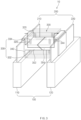
- FIG. 1 is a perspective view illustrating a first example of a structure of a current interrupt device in a state in which a battery module normally operates, which forms not part of the present invention.
- a battery module 10 may include a plurality of batteries 100.
- the plurality of batteries 100 may be secondary batteries, for example, lithium secondary batteries.
- a first battery 110 and a second battery 120 are illustrated as constituents of the plurality of batteries 100.
- the battery module 10 may include three or more batteries.
- a lead 200 may be provided in each of the plurality of batteries constituting the battery module according to the present invention.
- FIG. 1 illustrates a case in which a first lead 210 and a second lead 220 are respectively provided in the first battery 110 and a second battery 120.
- a current interrupt device 300 may be provided between the first battery 110 and the second battery 120.
- the current interrupt device 300 according to the first example may include a plurality of connection parts including an inclined surface. That is, as illustrated in FIG. 1 , the current interrupt device 300 according to the first example may include a first connection part 302 having one surface on which an inclined surface SL (see FIG. 2 ) is formed and a second connection part 304 having an inclined surface corresponding to the inclined surface of the first connection part 302.
- the inclined surfaces correspond to each other may mean that the inclined surfaces face each other.
- the inclined surface of the first connection part 302 and the inclined surface of the second connection part 304 may have the same shape and size.
- first connection part 302 may be connected and fixed to the first battery 110
- second connection part 304 may be connected and fixed to the second battery 120
- a first fixing part 342 coupled to a portion of a circumferential portion of the first battery 110 may be provided on an outer portion of the first connection part 302
- a second fixing part 344 coupled to a portion of a circumferential portion of the second battery 120 may be provided on an outer portion of the second connection part 304.
- the first fixing part 342 may be provided on one surface, on which the first connection part 302 is provided, of both surfaces of the first battery 110
- the second fixing part 344 may be provided on one surface on which the second connection part 304 is provided.
- first fixing part 342 may be coupled to the first lead 210 of the first battery 110
- second fixing part 344 may be coupled to the second lead 220 of the second battery 120.
- an adhesion material may be applied to at least a portion of the surface on which the first fixing part 342 and the circumferential portion of the first battery 110 are coupled to each other.
- the adhesion material may be applied to at least a portion of the surface on which the second fixing part 344 and the circumferential portion of the second battery 120 are coupled to each other.
- the first connection part 302 and the second connection part 304 may be respectively connected to the first battery 110 and the second battery 120.
- the inclined surfaces of the first connection part 302 and the second connection part 304 may contact each other to form a contact surface.
- an adhesion part 310 having adhesion force so that the inclined surface of the first connection part 302 and the inclined surface of the second connection part 304 adhere to each other may be formed between the first connection part 302 and the second connection part 304.
- the first connection part 302 and the second connection part 304 may be electrically connected to each other.
- the electrical connection may mean that current flows between the first connection part 302 and the second connection part 304.
- the adhesion part 310 may include a material having electrical conductivity.
- the current interrupt device 300 may be generally provided between the first battery 110 and the second battery 120 to electrically connect the first battery 110 and the second battery 120 to each other.
- the overcharged battery is swollen due to vaporization of the electrolyte and an increase in thickness of the electrode assembly.
- FIG. 2 is a perspective view illustrating a principle of interrupting current by the current interrupt device according to the first example when the battery module is overcharged.
- the first battery 110 when the first battery 110 is swollen, the first battery 110 may apply external force from the first connection part 302 toward the inclined surface of the first connection part 302.
- the second battery 120 when the second battery 120 is swollen, the second battery may apply external force from the second connection part 304 toward the inclined surface of the second connection part 304.
- the current interrupt device 300 in addition to the first connection part 302 and the second connection part 304 may not be deformed. This is done because the adhesion force due to the adhesion part 310 exists between the inclined surface of the first connection part 302 and the inclined surface of the second connection part 304.
- the external force acting on the first connection 302 or the second connection part 304 is equal to or greater than predetermined force, it may be difficult to maintain the adhesion between the first connection part 302 and the second connection part 304 through only the adhesion force between the inclined surface of the first connection part 302 and the inclined surface of the second connection part 304.
- the inclined surface of the first connection part 302 and the inclined surface of the second connection part 304 are dislocated with respect to each other, and thus, the first connection part 302 and the second connection part 304 are electrically interrupted with respect to each other.
- the first battery 110 and the second battery 120 may be electrically interrupted with respect to each other to stop an operation of the battery module 10.
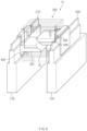
- FIG. 3 is a perspective view illustrating a second example of a structure of the current interrupt device in a state in which the battery module normally operates according to the present invention.
- a current interrupt device According to a current interrupt device according to a second example of the present invention, if external force equal to or greater than predetermined force is applied to a first connection part 302 and a second connection part 304, the inclined surface SL (see FIG. 4 ) of the first connection part 302 and the inclined surface of the second connection part 304 may be dislocated with respect to each other, and thus, the first connection part 302 and the second connection part 304 may be electrically interrupted.
- the current interrupt devices according to the first and second examples of the present invention may be similar to each other.
- the current interrupt device according to the second example of the present invention is different from the current interrupt device according to the first example of the present invention in terms of a detailed configuration for realizing the above principle.
- the current interrupt device according to the second example of the present invention will be described with a focus on differences from the current interrupt device according to the first example of the present invention.
- the current interrupt device 300 includes a pressing part 320 disposed above or below the first connection part 302 and the second connection part 304 to press the first connection part 302 and the second connection part 304 upward or downward.
- the pressing part is provided above and below the first connection part 302 and the second connection part 304.
- the pressing part 320 disposed above the first connection part 302 and the second connection part 304 presses the first connection part 302 and the second connection part 304 downward
- the pressing part 320 disposed below the first connection part 302 and the second connection part 304 presses the first connection part 302 and the second connection part 304 upward.
- the pressing part 320 may be a constituent having elasticity.
- the pressing part 320 may have a spring structure.
- the pressing part may be supported by a different constituent.
- the current interrupt device 300 may include a support part 330 supporting the pressing part 320 so that the pressing part 320 presses the first connection part 302 and the second connection part 304.
- the support part 330 may include a first support part 332 provided below the pressing part 320 to support the pressing part 320 provided below the first connection part 302 and the second connection part 304 and a second support part 334 provided above the pressing part 320 to support the pressing part 320 disposed above the first connection part 302 and the second connection part 304.
- FIG. 4 is a perspective view illustrating a principle of interrupting current by the current interrupt device according to the second example when the battery module is overcharged.
- the first battery 110 when the first battery 110 is swollen, the first battery 110 may apply external force from the first connection part 302 toward the inclined surface of the first connection part 302.
- the second battery 120 when the second battery 120 is swollen, the second battery may apply external force from the second connection part 304 toward the inclined surface of the second connection part 304.
- the current interrupt device 300 in addition to the first connection part 302 and the second connection part 304 may not be deformed. This is done because the pressing part 320 presses the first connection part 302 and the second connection part 304 upward or downward so that static frictional force acts between the inclined surface of the first connection part 302 and the inclined surface of the second connection part 304.
- the external force acting on the first connection 302 or the second connection part 304 is equal to or greater than predetermined force, it may be difficult to maintain the contact between the first connection part 302 and the second connection part 304 through only the static frictional force between the inclined surface of the first connection part 302 and the inclined surface of the second connection part 304.
- the inclined surface of the first connection part 302 and the inclined surface of the second connection part 304 are dislocated with respect to each other, and thus, the first connection part 302 and the second connection part 304 are electrically interrupted.
- the first battery 110 and the second battery 120 may be electrically cut off to stop an operation of the battery module 10.
- FIG. 5 is a perspective view illustrating a third example of a structure of a current interrupt device in a state in which a battery module normally operates according to the present invention
- FIG. 6 is a perspective view illustrating a principle of interrupting current by the current interrupt device according to the third example when the battery module is overcharged.
- a current interrupt device 300 according to a third example of the present invention may have a structure in which the adhesion part 310 of the current interrupt device according to the first example of the present invention and the pressing parts 320 and the support part 330 of the current interrupt device according to the second example of the present invention are coupled to each other.
- the current interrupt device 300 according to the third example of the present invention descriptions of an adhesion part 310, a pressing part 320, and a support part 330 are substituted for those of the current interrupt devices according to the first and second examples of the present invention.
- the inclined surface of the first connection part and the inclined surface of the second connection part may be dislocated with respect to each other to interrupt the electrical connection between the first connection part and the second connection part.
- the magnitude of the external force when the electrical connection between the first connection part and the second connection part is interrupted may depend on the adhesion strength of the adhesion part or the strength at which the pressing part presses the first connection part and the second connection part.
- the strength at which the pressing part presses the first connection part and the second connection part may depend on an elastic modulus of the entire pressing part.
- the elastic modulus of the entire pressing part may be defined as magnitude of force required to deform the entire pressing part provided in the current interrupt device by a unit length.
- the adhesion strength of the adhesion part or the elastic modulus of the entire pressing part is too large in the current interrupt device according to the present invention, the external force at which the electrical interruption occurs may be too large. As a result, there is a problem in that safety of the battery module is not ensured due to the fact that the electrical interruption does not occur even though the electrical interruption has to occur.
- the swelling of the battery may occur not only in an overcharged state but also a state in which the battery is stored at a high temperature.
- the battery is simply stored at the high temperature, possibility of ignition of the battery is low, and thus, the interruption of the current may be unnecessary.
- the adhesion strength of the adhesion part or the elastic modulus of the entire pressing part is too small in the current interrupt device according to the present invention, even when the battery or the battery module is merely stored at the high temperature, the current interruption may occur, and a defective rate of the battery module may increase.
- the adhesion strength of the adhesion part or the elastic modulus with respect to the entire pressing part is properly set within a predetermined range when manufacturing the current interrupt device and manufacturing the battery module.
- Embodiments and Experimental Examples are merely examples as illustrative purpose, and thus, the technical scope of the present invention is not limited thereto.
- Embodiment 1 of the present invention a pressing part was used in a current interrupt device.
- An elastic modulus with respect to the entire pressing part was 3 kgf/cm.
- the current interrupt device according to Embodiment 1 was mounted in a battery module to manufacture the battery module. Then, the battery module was overcharged or stored at a high temperature to measure whether the current interrupt device operates.
- Embodiment 2 of the present invention a pressing part was used in a current interrupt device.
- An elastic modulus with respect to the entire pressing part was 5 kgf/cm.
- the current interrupt device according to Embodiment 2 was mounted in a battery module to manufacture the battery module. Then, the battery module was overcharged or stored at a high temperature to measure whether the current interrupt device operates.
- the overcharging condition of the battery module and the high-temperature storage condition of the battery module in Embodiment 2 are the same as those in Embodiment 1.
- an adhesion part and a pressing part were used together in a current interrupt device.
- Adhesion strength of the adhesion part was 1 kgf/cm
- an elastic modulus with respect to the entire pressing part was 1 kgf/cm.
- the adhesion strength of the adhesion part is defined as force required when each of both constituents are stretched by a unit length on an adhesion surface when both the constituents are stretched after both the constituents adhere to each other.
- the current interrupt device according to Embodiment 3 was mounted in a battery module to manufacture the battery module. Then, the battery module was overcharged or stored at a high temperature to measure whether the current interrupt device operates.
- the overcharging condition of the battery module and the high-temperature storage condition of the battery module in Embodiment 3 are the same as those in Embodiment 1.
- Embodiment 4 of the present invention an adhesion part and a pressing part were used together in a current interrupt device.
- Adhesion strength of the adhesion part was 1 kgf/cm
- an elastic modulus with respect to the entire pressing part was 3 kgf/cm.
- the current interrupt device according to Embodiment 4 was mounted in a battery module to manufacture the battery module. Then, the battery module was overcharged or stored at a high temperature to measure whether the current interrupt device operates.
- the overcharging condition of the battery module and the high-temperature storage condition of the battery module in Embodiment 4 are the same as those in Embodiment 1.
- an adhesion part was used in a current interrupt device.
- Adhesion strength of the adhesion part was 2 kgf/cm.
- the current interrupt device according to Embodiment 5 was mounted in a battery module to manufacture the battery module. Then, the battery module was overcharged or stored at a high temperature to measure whether the current interrupt device operates.
- the overcharging condition of the battery module and the high-temperature storage condition of the battery module in Embodiment 5 are the same as those in Embodiment 1.
- Embodiment 6 of the present invention an adhesion part and a pressing part were used together in a current interrupt device.
- Adhesion strength of the adhesion part was 2 kgf/cm
- an elastic modulus with respect to the entire pressing part was 2 kgf/cm.
- the current interrupt device according to Embodiment 6 was mounted in a battery module to manufacture the battery module. Then, the battery module was overcharged or stored at a high temperature to measure whether the current interrupt device operates.
- the overcharging condition of the battery module and the high-temperature storage condition of the battery module in Embodiment 6 are the same as those in Embodiment 1.
- Comparative Example 1 of the present invention a pressing part was used in a current interrupt device.
- An elastic modulus with respect to the entire pressing part was 1 kgf/cm.
- the current interrupt device according to Comparative Example 1 was mounted in a battery module to manufacture the battery module. Then, the battery module was overcharged or stored at a high temperature to measure whether the current interrupt device operates.
- the overcharging condition of the battery module and the high-temperature storage condition of the battery module in Comparative Example 1 are the same as those in Embodiment 1.
- Comparative Example 2 of the present invention a pressing part was used in a current interrupt device.
- An elastic modulus with respect to the entire pressing part was 7 kgf/cm.
- the current interrupt device according to Comparative Example 2 was mounted in a battery module to manufacture the battery module. Then, the battery module was overcharged or stored at a high temperature to measure whether the current interrupt device operates.
- the overcharging condition of the battery module and the high-temperature storage condition of the battery module in Comparative Example 2 are the same as those in Embodiment 1.
- the current interrupt device according to Comparative Example 3 was mounted in a battery module to manufacture the battery module. Then, the battery module was overcharged or stored at a high temperature to measure whether the current interrupt device operates.
- the overcharging condition of the battery module and the high-temperature storage condition of the battery module in Comparative Example 3 are the same as those in Embodiment 1.
- Comparative Example 4 of the present invention an adhesion part and a pressing part were used together in a current interrupt device.
- Adhesion strength of the adhesion part was 1 kgf/cm
- an elastic modulus with respect to the entire pressing part was 5 kgf/cm.
- the current interrupt device according to Comparative Example 4 was mounted in a battery module to manufacture the battery module. Then, the battery module was overcharged or stored at a high temperature to measure whether the current interrupt device operates.
- the overcharging condition of the battery module and the high-temperature storage condition of the battery module in Comparative Example 4 are the same as those in Embodiment 1.
- Comparative Example 5 of the present invention an adhesion part and a pressing part were used together in a current interrupt device.
- Adhesion strength of the adhesion part was 2 kgf/cm
- an elastic modulus with respect to the entire pressing part was 5 kgf/cm.
- the current interrupt device according to Comparative Example 5 was mounted in a battery module to manufacture the battery module. Then, the battery module was overcharged or stored at a high temperature to measure whether the current interrupt device operates.
- the overcharging condition of the battery module and the high-temperature storage condition of the battery module in Comparative Example 5 are the same as those in Embodiment 1.
- the overcharging conditions of the battery module are as follows.
- the battery module in which five batteries, each of which has a voltage of 4.2 V when a state of charge (SOC) is 100%, are connected in series to each other were overcharged by 50% so that the entire battery module has a voltage of 31.5 V (4.2V * 5 * 1.5).
- SOC state of charge
- the high-temperature storage conditions of the battery module are as follows. In Embodiment 2, the battery module was charged so that the state of charge (SOC) of the battery module is 100% and then was stored for 8 weeks in a chamber at 60 degrees Celsius.
- SOC state of charge
- the sum of the adhesion strength of the adhesion part and the elastic strength of the entire pressing part was 3 kgf/cm, 5 kgf/cm, 2 kgf/cm, 4 kgf/cm, 2 kgf/cm, and 4 kgf/cm.
- the current interruption occurred, and in the current interruption device of Experimental Example 2, the current interruption did not occur.
- the adhesion strength of the adhesion part or the elastic modulus with respect to the entire pressing part is too large, the external force causing the electrical interception becomes too large. As a result, the electrical interception does not occur even though the electrical interception had to occur, and thus, the safety of the battery module may not be secured.
- the adhesion strength of the adhesion part or the elastic modulus of the entire pressing part is too small, even when the battery or the battery module is merely stored at the high temperature, the current interruption may occur, and thus, the defective rate of the battery module may increase.
- Embodiments 1 to 6 as shown in Table 1, it was confirmed that when the electrical interruption is required, the electrical interception is performed to secure the safety of the battery module, and when the battery module is in the high-temperature storage state, no failure occurs in the battery module because the electrical interruption does not occur.
- each of the adhesion strength of the adhesion part or the elastic strength with respect to the entire pressing part was 7 kgf/cm, 6 kfg/cm, and 7 kfg/cm.
- Experimental Example 2 it was confirmed that when the battery module is in the high-temperature storage state, the battery module isn't defective due to no electrical interruption, but in Experimental Example 1, the safety of the battery module is not ensured due to no electrical interruption in the overcharged state.
Landscapes
- Chemical & Material Sciences (AREA)
- Chemical Kinetics & Catalysis (AREA)
- Electrochemistry (AREA)
- General Chemical & Material Sciences (AREA)
- Engineering & Computer Science (AREA)
- Manufacturing & Machinery (AREA)
- Materials Engineering (AREA)
- Battery Mounting, Suspending (AREA)
- Connection Of Batteries Or Terminals (AREA)
Description
- The present application claims the benefit of the priority of
Korean Patent Application No. 10-2018-0017174, filed on February 12, 2018 - The present invention relates to a current interrupt device and a battery module including the same, and more particularly, to a current interrupt device that is capable of improving safety of a battery module and a battery module including the same.
- As demands of secondary batteries, which are repeatedly chargeable and dischargeable, increase, the importance of safety of secondary batteries is also increasing. For example, an increase of a capacity per unit volume of a secondary battery is required. As the capacity per unit volume of the secondary battery increases, safety of the secondary battery tends to be more vulnerable. Thus, the safety of the secondary battery needs to be improved as well as the capacity of the secondary battery. Particularly, when a lithium secondary battery is overcharged, a risk of ignition of the lithium secondary battery increases. Thus, it is essential to secure the safety in the lithium secondary battery.
- According to the related art, in order to solve the problem of the ignition within the secondary battery, a technique of adding an anti-ignition material or the like to an electrolyte that is charged in the secondary battery is being used, or a technique of mounting a device such as a current interrupt device (CID) within the secondary battery is being used.
- However, the safety devices of the secondary battery according to the related art are constituents for securing the safety of one secondary battery. Thus, in the case of a battery module in which a plurality of secondary batteries is assembled, there is a problem that the safety of the battery module is limited by only the safety device according to the related art.
- For example, in the case of the battery module, since the secondary batteries are electrically connected to each other, a temperature of the entire battery module rapidly increases due to electrical interaction between the secondary batteries. Thus, it is necessary to secure safety in an aspect of the battery module separately from the individual safety of the secondary battery.
- An example of current interrupt device for safely connecting to secondary batteries is disclosed in document
US 2016/268584 A1 , which forms the basis for the preamble of claim 1. However, such a device can be further improved. - To solve the above problem, an object of the present invention is to improve safety of a battery module by preventing ignition that may occur due to electrical interaction between secondary batteries in the battery module from occurring.
- According to one aspect of the present invention, a current interrupt device is defined in the appended set of claims. The current interrupt device includes: a first connection part having one surface on which an inclined surface is formed; and a second connection part having one surface on which an inclined surface having a shape corresponding to the inclined surface of the first connection part is formed, wherein the inclined surface of the first connection part and the inclined surface of the second connection part contact each other to form a contact surface, the first connection part and the second connection part are electrically connected to each other, and when external force equal to or greater than predetermined force is applied to the inclined surface of the first connection part or the inclined surface of the second connection part, the inclined surface of the first connection part and the inclined surface of the second connection part are dislocated with respect to each other on the contact surface to interrupt electrical connection between the first connection part and the second connection.
- The current interrupt device may further include an adhesion part disposed on the contact surface so that the inclined surface of the first connection part and the inclined surface of the second connection part adhere to each other.
- The current interrupt device further includes a pressing part disposed above or below the first connection part and the second connection part to press the first connection part and the second connection part downward or upward.
- The current interrupt device may further include a support part supporting the pressing part so that the pressing part presses the first connection part and the second connection part.
- The pressing part is disposed above and below the first connection part and the second connection part, and the pressing part presses the first connection part and the second connection part downward and upward.
- The current interrupt device may further include a fixing part disposed on an outer portion of the first connection part and the outer portion of the second connection part so that the first connection part and the second connection part are coupled to a portion of a circumferential portion of the secondary battery.
- The current interrupt device may further include a pressing part disposed above or below the first connection part and the second connection part to press the first connection part and the second connection part upward or downward, wherein the sum of adhesion strength (kgf/cm) of the adhesion part and an elastic modulus (kgf/cm) of the pressing part may be 2 kgf/cm to 5 kgf/cm.
- According to another aspect of the present invention, a battery module is defined in the appended set of claims. The battery module includes: a first battery; a second battery spaced apart from the first battery; and a current interrupt device disposed between the first battery and the second battery, wherein the current interrupt device includes: a first connection part having one surface on which an inclined surface is formed; and a second connection part having one surface on which an inclined surface having a shape corresponding to the inclined surface of the first connection part is formed, wherein the inclined surface of the first connection part and the inclined surface of the second connection part contact each other to form a contact surface, the first connection part and the second connection part are electrically connected to each other, and when external force equal to or greater than predetermined force is applied to the inclined surface of the first connection part or the inclined surface of the second connection part, the inclined surface of the first connection part and the inclined surface of the second connection part are dislocated with respect to each other on the contact surface to interrupt electrical connection between the first connection part and the second connection.
- According to the present invention, the ignition that may occur due to the electrical interaction between the secondary batteries in the battery module may be prevented to improve the safety of the battery module.
-
-
FIG. 1 is a perspective view illustrating a first example of a structure of a current interrupt device in a state in which a battery module normally operates, which forms not part of the present invention. -
FIG. 2 is a perspective view illustrating a principle of interrupting current by the current interrupt device according to the first example when the battery module is overcharged. -
FIG. 3 is a perspective view illustrating a second example of a structure of a current interrupt device in a state in which a battery module normally operates according to the present invention. -
FIG. 4 is a perspective view illustrating a principle of interrupting current by the current interrupt device according to the second example when the battery module is overcharged. -
FIG. 5 is a perspective view illustrating a third example of a structure of a current interrupt device in a state in which a battery module normally operates according to the present invention. -
FIG. 6 is a perspective view illustrating a principle of interrupting current by the current interrupt device according to the third example when the battery module is overcharged. - Hereinafter, a structure of a current interrupt device according to the present invention will be described with reference to the accompanying drawings in
Fig.3 - Fig.6 . -
FIG. 1 is a perspective view illustrating a first example of a structure of a current interrupt device in a state in which a battery module normally operates, which forms not part of the present invention. - As illustrated in
FIG. 1 , abattery module 10 may include a plurality ofbatteries 100. The plurality ofbatteries 100 may be secondary batteries, for example, lithium secondary batteries. InFIG. 1 , afirst battery 110 and asecond battery 120 are illustrated as constituents of the plurality ofbatteries 100. However, thebattery module 10 may include three or more batteries. Alead 200 may be provided in each of the plurality of batteries constituting the battery module according to the present invention.FIG. 1 illustrates a case in which afirst lead 210 and asecond lead 220 are respectively provided in thefirst battery 110 and asecond battery 120. - A
current interrupt device 300 may be provided between thefirst battery 110 and thesecond battery 120. - As illustrated in
FIG. 1 , thecurrent interrupt device 300 according to the first example, not forming part of the present invention, may include a plurality of connection parts including an inclined surface. That is, as illustrated inFIG. 1 , thecurrent interrupt device 300 according to the first example may include afirst connection part 302 having one surface on which an inclined surface SL (seeFIG. 2 ) is formed and asecond connection part 304 having an inclined surface corresponding to the inclined surface of thefirst connection part 302. Here, that the inclined surfaces correspond to each other may mean that the inclined surfaces face each other. Also, the inclined surface of thefirst connection part 302 and the inclined surface of thesecond connection part 304 may have the same shape and size. - Also, the
first connection part 302 may be connected and fixed to thefirst battery 110, and thesecond connection part 304 may be connected and fixed to thesecond battery 120. For this, afirst fixing part 342 coupled to a portion of a circumferential portion of thefirst battery 110 may be provided on an outer portion of thefirst connection part 302, and asecond fixing part 344 coupled to a portion of a circumferential portion of thesecond battery 120 may be provided on an outer portion of thesecond connection part 304. As illustrated inFIG. 1 , thefirst fixing part 342 may be provided on one surface, on which thefirst connection part 302 is provided, of both surfaces of thefirst battery 110, and thesecond fixing part 344 may be provided on one surface on which thesecond connection part 304 is provided. Also, thefirst fixing part 342 may be coupled to thefirst lead 210 of thefirst battery 110, and thesecond fixing part 344 may be coupled to thesecond lead 220 of thesecond battery 120. Also, although not shown in the drawings, an adhesion material may be applied to at least a portion of the surface on which thefirst fixing part 342 and the circumferential portion of thefirst battery 110 are coupled to each other. Also, the adhesion material may be applied to at least a portion of the surface on which thesecond fixing part 344 and the circumferential portion of thesecond battery 120 are coupled to each other. - The
first connection part 302 and thesecond connection part 304 may be respectively connected to thefirst battery 110 and thesecond battery 120. The inclined surfaces of thefirst connection part 302 and thesecond connection part 304 may contact each other to form a contact surface. Also, anadhesion part 310 having adhesion force so that the inclined surface of thefirst connection part 302 and the inclined surface of thesecond connection part 304 adhere to each other may be formed between thefirst connection part 302 and thesecond connection part 304. In this specification and attached claims, even when the adhesion part is provided between thefirst connection part 302 and thesecond connection part 304, it should be interpreted that the inclined surfaces of thefirst connection part 302 and thesecond connection part 304 may contact each other. - The
first connection part 302 and thesecond connection part 304 may be electrically connected to each other. Here, the electrical connection may mean that current flows between thefirst connection part 302 and thesecond connection part 304. To electrically connect thefirst connection part 302 to thesecond connection part 304, theadhesion part 310 may include a material having electrical conductivity. - As illustrated in
FIG. 1 , the current interruptdevice 300 according to the first example may be generally provided between thefirst battery 110 and thesecond battery 120 to electrically connect thefirst battery 110 and thesecond battery 120 to each other. - When a portion or whole of the plurality of batteries constituting the battery module is overcharged, the overcharged battery is swollen due to vaporization of the electrolyte and an increase in thickness of the electrode assembly.
-
FIG. 2 is a perspective view illustrating a principle of interrupting current by the current interrupt device according to the first example when the battery module is overcharged. - Referring to
FIG. 2 , when thefirst battery 110 is swollen, thefirst battery 110 may apply external force from thefirst connection part 302 toward the inclined surface of thefirst connection part 302. When thesecond battery 120 is swollen, the second battery may apply external force from thesecond connection part 304 toward the inclined surface of thesecond connection part 304. - When the external forces are applied toward the inclined surface of the
first connection part 302 or thesecond connection part 304 by thefirst connection part 302 or thesecond connection part 304, if the applied external force is less than predetermined force, the current interruptdevice 300 in addition to thefirst connection part 302 and thesecond connection part 304 may not be deformed. This is done because the adhesion force due to theadhesion part 310 exists between the inclined surface of thefirst connection part 302 and the inclined surface of thesecond connection part 304. - However, if the external force acting on the
first connection 302 or thesecond connection part 304 is equal to or greater than predetermined force, it may be difficult to maintain the adhesion between thefirst connection part 302 and thesecond connection part 304 through only the adhesion force between the inclined surface of thefirst connection part 302 and the inclined surface of thesecond connection part 304. Thus, as illustrated inFIG. 2 , the inclined surface of thefirst connection part 302 and the inclined surface of thesecond connection part 304 are dislocated with respect to each other, and thus, thefirst connection part 302 and thesecond connection part 304 are electrically interrupted with respect to each other. Thus, thefirst battery 110 and thesecond battery 120 may be electrically interrupted with respect to each other to stop an operation of thebattery module 10. -
FIG. 3 is a perspective view illustrating a second example of a structure of the current interrupt device in a state in which the battery module normally operates according to the present invention. - According to a current interrupt device according to a second example of the present invention, if external force equal to or greater than predetermined force is applied to a
first connection part 302 and asecond connection part 304, the inclined surface SL (seeFIG. 4 ) of thefirst connection part 302 and the inclined surface of thesecond connection part 304 may be dislocated with respect to each other, and thus, thefirst connection part 302 and thesecond connection part 304 may be electrically interrupted. In this point, the current interrupt devices according to the first and second examples of the present invention may be similar to each other. However, the current interrupt device according to the second example of the present invention is different from the current interrupt device according to the first example of the present invention in terms of a detailed configuration for realizing the above principle. Hereinafter, the current interrupt device according to the second example of the present invention will be described with a focus on differences from the current interrupt device according to the first example of the present invention. - As illustrated in
FIG. 3 , the current interruptdevice 300 according to the second example of the present invention includes apressing part 320 disposed above or below thefirst connection part 302 and thesecond connection part 304 to press thefirst connection part 302 and thesecond connection part 304 upward or downward. For example, as illustrated inFIG. 3 , the pressing part is provided above and below thefirst connection part 302 and thesecond connection part 304. Thepressing part 320 disposed above thefirst connection part 302 and thesecond connection part 304 presses thefirst connection part 302 and thesecond connection part 304 downward, and thepressing part 320 disposed below thefirst connection part 302 and thesecond connection part 304 presses thefirst connection part 302 and thesecond connection part 304 upward. Here, thepressing part 320 may be a constituent having elasticity. For example, thepressing part 320 may have a spring structure. - To press the
first connection part 302 or thesecond connection part 304, the pressing part may be supported by a different constituent. For this, the current interruptdevice 300 according to the second example of the present invention may include asupport part 330 supporting thepressing part 320 so that thepressing part 320 presses thefirst connection part 302 and thesecond connection part 304. - Here, as illustrated n
FIG. 3 , when thepressing part 320 is provided above and below thefirst connection part 302 and thesecond connection part 304, thesupport part 330 may include a first support part 332 provided below thepressing part 320 to support thepressing part 320 provided below thefirst connection part 302 and thesecond connection part 304 and asecond support part 334 provided above thepressing part 320 to support thepressing part 320 disposed above thefirst connection part 302 and thesecond connection part 304. -
FIG. 4 is a perspective view illustrating a principle of interrupting current by the current interrupt device according to the second example when the battery module is overcharged. - Referring to
FIG. 4 , when thefirst battery 110 is swollen, thefirst battery 110 may apply external force from thefirst connection part 302 toward the inclined surface of thefirst connection part 302. When thesecond battery 120 is swollen, the second battery may apply external force from thesecond connection part 304 toward the inclined surface of thesecond connection part 304. - When the external forces are applied toward the inclined surface of the
first connection part 302 or thesecond connection part 304 by thefirst connection part 302 or thesecond connection part 304, if the applied external force is less than predetermined force, the current interruptdevice 300 in addition to thefirst connection part 302 and thesecond connection part 304 may not be deformed. This is done because thepressing part 320 presses thefirst connection part 302 and thesecond connection part 304 upward or downward so that static frictional force acts between the inclined surface of thefirst connection part 302 and the inclined surface of thesecond connection part 304. - However, if the external force acting on the
first connection 302 or thesecond connection part 304 is equal to or greater than predetermined force, it may be difficult to maintain the contact between thefirst connection part 302 and thesecond connection part 304 through only the static frictional force between the inclined surface of thefirst connection part 302 and the inclined surface of thesecond connection part 304. Thus, as illustrated inFIG. 4 , the inclined surface of thefirst connection part 302 and the inclined surface of thesecond connection part 304 are dislocated with respect to each other, and thus, thefirst connection part 302 and thesecond connection part 304 are electrically interrupted. Thus, thefirst battery 110 and thesecond battery 120 may be electrically cut off to stop an operation of thebattery module 10. -
FIG. 5 is a perspective view illustrating a third example of a structure of a current interrupt device in a state in which a battery module normally operates according to the present invention, andFIG. 6 is a perspective view illustrating a principle of interrupting current by the current interrupt device according to the third example when the battery module is overcharged. - A current interrupt
device 300 according to a third example of the present invention may have a structure in which theadhesion part 310 of the current interrupt device according to the first example of the present invention and thepressing parts 320 and thesupport part 330 of the current interrupt device according to the second example of the present invention are coupled to each other. In the current interruptdevice 300 according to the third example of the present invention, descriptions of anadhesion part 310, apressing part 320, and asupport part 330 are substituted for those of the current interrupt devices according to the first and second examples of the present invention. - in the current interrupt devices according to the first to third examples of the present invention, when the external force equal to or greater than the predetermined force is applied, the inclined surface of the first connection part and the inclined surface of the second connection part may be dislocated with respect to each other to interrupt the electrical connection between the first connection part and the second connection part. Thus, the magnitude of the external force when the electrical connection between the first connection part and the second connection part is interrupted may depend on the adhesion strength of the adhesion part or the strength at which the pressing part presses the first connection part and the second connection part. Particularly, when the pressing part has elasticity, the strength at which the pressing part presses the first connection part and the second connection part may depend on an elastic modulus of the entire pressing part. Here, when the pressing part is provided in plurality, the elastic modulus of the entire pressing part may be defined as magnitude of force required to deform the entire pressing part provided in the current interrupt device by a unit length.
- However, when the adhesion strength of the adhesion part or the elastic modulus of the entire pressing part is too large in the current interrupt device according to the present invention, the external force at which the electrical interruption occurs may be too large. As a result, there is a problem in that safety of the battery module is not ensured due to the fact that the electrical interruption does not occur even though the electrical interruption has to occur.
- The swelling of the battery may occur not only in an overcharged state but also a state in which the battery is stored at a high temperature. However, the battery is simply stored at the high temperature, possibility of ignition of the battery is low, and thus, the interruption of the current may be unnecessary. However, if the adhesion strength of the adhesion part or the elastic modulus of the entire pressing part is too small in the current interrupt device according to the present invention, even when the battery or the battery module is merely stored at the high temperature, the current interruption may occur, and a defective rate of the battery module may increase. Thus, to secure the safety of the battery module and simultaneously minimize the defective rate of the battery module, it is necessary that the adhesion strength of the adhesion part or the elastic modulus with respect to the entire pressing part is properly set within a predetermined range when manufacturing the current interrupt device and manufacturing the battery module.
- Hereinafter, the contents of the present invention will be described in more detail through Embodiments and Experimental Examples. However, Embodiments and Experimental Examples are merely examples as illustrative purpose, and thus, the technical scope of the present invention is not limited thereto.
- In Embodiment 1 of the present invention, a pressing part was used in a current interrupt device. An elastic modulus with respect to the entire pressing part was 3 kgf/cm.
- The current interrupt device according to Embodiment 1 was mounted in a battery module to manufacture the battery module. Then, the battery module was overcharged or stored at a high temperature to measure whether the current interrupt device operates.
- In Embodiment 2 of the present invention, a pressing part was used in a current interrupt device. An elastic modulus with respect to the entire pressing part was 5 kgf/cm.
- The current interrupt device according to Embodiment 2 was mounted in a battery module to manufacture the battery module. Then, the battery module was overcharged or stored at a high temperature to measure whether the current interrupt device operates. The overcharging condition of the battery module and the high-temperature storage condition of the battery module in Embodiment 2 are the same as those in Embodiment 1.
- In Embodiment 3 of the present invention, an adhesion part and a pressing part were used together in a current interrupt device. Adhesion strength of the adhesion part was 1 kgf/cm, and an elastic modulus with respect to the entire pressing part was 1 kgf/cm. The adhesion strength of the adhesion part is defined as force required when each of both constituents are stretched by a unit length on an adhesion surface when both the constituents are stretched after both the constituents adhere to each other.
- The current interrupt device according to Embodiment 3 was mounted in a battery module to manufacture the battery module. Then, the battery module was overcharged or stored at a high temperature to measure whether the current interrupt device operates. The overcharging condition of the battery module and the high-temperature storage condition of the battery module in Embodiment 3 are the same as those in Embodiment 1.
- In Embodiment 4 of the present invention, an adhesion part and a pressing part were used together in a current interrupt device. Adhesion strength of the adhesion part was 1 kgf/cm, and an elastic modulus with respect to the entire pressing part was 3 kgf/cm.
- The current interrupt device according to Embodiment 4 was mounted in a battery module to manufacture the battery module. Then, the battery module was overcharged or stored at a high temperature to measure whether the current interrupt device operates. The overcharging condition of the battery module and the high-temperature storage condition of the battery module in Embodiment 4 are the same as those in Embodiment 1.
- In Embodiment 5 of the present invention, an adhesion part was used in a current interrupt device. Adhesion strength of the adhesion part was 2 kgf/cm.
- The current interrupt device according to Embodiment 5 was mounted in a battery module to manufacture the battery module. Then, the battery module was overcharged or stored at a high temperature to measure whether the current interrupt device operates. The overcharging condition of the battery module and the high-temperature storage condition of the battery module in Embodiment 5 are the same as those in Embodiment 1.
- In Embodiment 6 of the present invention, an adhesion part and a pressing part were used together in a current interrupt device. Adhesion strength of the adhesion part was 2 kgf/cm, and an elastic modulus with respect to the entire pressing part was 2 kgf/cm.
- The current interrupt device according to Embodiment 6 was mounted in a battery module to manufacture the battery module. Then, the battery module was overcharged or stored at a high temperature to measure whether the current interrupt device operates. The overcharging condition of the battery module and the high-temperature storage condition of the battery module in Embodiment 6 are the same as those in Embodiment 1.
- In Comparative Example 1 of the present invention, a pressing part was used in a current interrupt device. An elastic modulus with respect to the entire pressing part was 1 kgf/cm.
- The current interrupt device according to Comparative Example 1 was mounted in a battery module to manufacture the battery module. Then, the battery module was overcharged or stored at a high temperature to measure whether the current interrupt device operates. The overcharging condition of the battery module and the high-temperature storage condition of the battery module in Comparative Example 1 are the same as those in Embodiment 1.
- In Comparative Example 2 of the present invention, a pressing part was used in a current interrupt device. An elastic modulus with respect to the entire pressing part was 7 kgf/cm.
- The current interrupt device according to Comparative Example 2 was mounted in a battery module to manufacture the battery module. Then, the battery module was overcharged or stored at a high temperature to measure whether the current interrupt device operates. The overcharging condition of the battery module and the high-temperature storage condition of the battery module in Comparative Example 2 are the same as those in Embodiment 1.
- In Comparative Example 3 of the present invention, an adhesion part was used in a current interrupt device. Adhesion strength of the adhesion part was 1 kgf/cm.
- The current interrupt device according to Comparative Example 3 was mounted in a battery module to manufacture the battery module. Then, the battery module was overcharged or stored at a high temperature to measure whether the current interrupt device operates. The overcharging condition of the battery module and the high-temperature storage condition of the battery module in Comparative Example 3 are the same as those in Embodiment 1.
- In Comparative Example 4 of the present invention, an adhesion part and a pressing part were used together in a current interrupt device. Adhesion strength of the adhesion part was 1 kgf/cm, and an elastic modulus with respect to the entire pressing part was 5 kgf/cm.
- The current interrupt device according to Comparative Example 4 was mounted in a battery module to manufacture the battery module. Then, the battery module was overcharged or stored at a high temperature to measure whether the current interrupt device operates. The overcharging condition of the battery module and the high-temperature storage condition of the battery module in Comparative Example 4 are the same as those in Embodiment 1.
- In Comparative Example 5 of the present invention, an adhesion part and a pressing part were used together in a current interrupt device. Adhesion strength of the adhesion part was 2 kgf/cm, and an elastic modulus with respect to the entire pressing part was 5 kgf/cm.
- The current interrupt device according to Comparative Example 5 was mounted in a battery module to manufacture the battery module. Then, the battery module was overcharged or stored at a high temperature to measure whether the current interrupt device operates. The overcharging condition of the battery module and the high-temperature storage condition of the battery module in Comparative Example 5 are the same as those in Embodiment 1.
- In Experimental Example 1, the battery modules manufactured according to Embodiments 1 to 6 and Comparative Examples 1 to 5 were overcharged to measure whether the current interrupt devices interrupt current.
- The overcharging conditions of the battery module are as follows. The battery module in which five batteries, each of which has a voltage of 4.2 V when a state of charge (SOC) is 100%, are connected in series to each other were overcharged by 50% so that the entire battery module has a voltage of 31.5 V (4.2V * 5 * 1.5). In a state in which constant current flows when the battery module is overcharged, charging was performed for one hour.
- In Experimental Example 2, the battery modules manufactured according to Embodiments 1 to 6 and Comparative Examples 1 to 5 were stored at a high temperature to measure whether the current interrupt devices interrupt current.
- The high-temperature storage conditions of the battery module are as follows. In Embodiment 2, the battery module was charged so that the state of charge (SOC) of the battery module is 100% and then was stored for 8 weeks in a chamber at 60 degrees Celsius.
- Experimental Example 1 and Experimental Example 2 were conducted on the battery modules according to Examples and Comparative Examples, and the results are shown in Table 1 below.
[Table 1] Classificat ion Embodiment Comparative Example 1 2 3 4 5 6 1 2 3 4 5 Experime ntal Example 1 Interr upt Interr upt Interr upt Interr upt Interr upt Interr upt Interr upt Not interr upt Interr upt Not interr upt Not interr upt Experime ntal Example 2 Not interr upt Not interr upt Not interr upt Not interr upt Not interr upt Not interr upt interr upt Not interr upt Interr upt Not interr upt Not interr upt - Referring to Table 1 above, the sum of the adhesion strength of the adhesion part and the elastic strength of the entire pressing part was 3 kgf/cm, 5 kgf/cm, 2 kgf/cm, 4 kgf/cm, 2 kgf/cm, and 4 kgf/cm. Here, in the current interrupt device according to Experimental Example 1, the current interruption occurred, and in the current interruption device of Experimental Example 2, the current interruption did not occur.
- As described above, in the current interrupt device according to an embodiment, if the adhesion strength of the adhesion part or the elastic modulus with respect to the entire pressing part is too large, the external force causing the electrical interception becomes too large. As a result, the electrical interception does not occur even though the electrical interception had to occur, and thus, the safety of the battery module may not be secured. In the current interrupt device according to the present invention, if the adhesion strength of the adhesion part or the elastic modulus of the entire pressing part is too small, even when the battery or the battery module is merely stored at the high temperature, the current interruption may occur, and thus, the defective rate of the battery module may increase. However, in the case of Embodiments 1 to 6, as shown in Table 1, it was confirmed that when the electrical interruption is required, the electrical interception is performed to secure the safety of the battery module, and when the battery module is in the high-temperature storage state, no failure occurs in the battery module because the electrical interruption does not occur.
- On the other hand, in the case of Comparative Examples 1 and 3, the adhesion strength of the adhesion part or the elastic strength with respect to the entire pressing part was 1 kgf/cm. In this case, in Experimental Example 1, it was confirmed that although the safety of the battery module is ensured by the occurrence of the electrical interruption, even if the battery module is in the high-temperature storage state, the battery module is defective by the occurrence of the electrical interruption.
- Also, in the case of Comparative Examples 2, 4, and 5, each of the adhesion strength of the adhesion part or the elastic strength with respect to the entire pressing part was 7 kgf/cm, 6 kfg/cm, and 7 kfg/cm. In this case, in Experimental Example 2, it was confirmed that when the battery module is in the high-temperature storage state, the battery module isn't defective due to no electrical interruption, but in Experimental Example 1, the safety of the battery module is not ensured due to no electrical interruption in the overcharged state.
- Thus, in the current interrupt device according to the present invention, it is confirmed that when the sum of the adhesion strength of the adhesion part and the elastic strength of the entire pressing part is 2 kgf/cm to 5 kgf/cm, the safety of the battery module is ensured, and the problem of the failure of the battery module is solved.
- While the embodiments of the present invention have been described with reference to the specific embodiments, it will be apparent to those skilled in the art that various changes and modifications may be made without departing from the scope of the invention as defined in the following claims.
Claims (6)
- A current interrupt device comprising:a first connection part (302) having one surface on which an inclined surface is formed; anda second connection part (304) having one surface on which an inclined surface having a shape corresponding to the inclined surface of the first connection part (302) is formed, wherein the inclined surface of the first connection part (302) and the inclined surface of the second connection part (304) contact each other to form a contact surface,wherein the first connection part (302) and the second connection part (302) are electrically connected to each other; andwherein, when external force equal to or greater than predetermined force is applied to the inclined surface of the first connection part (302) or the inclined surface of the second connection part (304), the inclined surface of the first connection part (302) and the inclined surface of the second connection part (304) are dislocated with respect to each other on the contact surface to interrupt electrical connection between the first connection part (302) and the second connection part (304),characterized in that the current interrupt device further comprises:a pressing part (320) disposed above the first connection part (302) and the second connection part (304) to press the first connection part and the second connection part downward, anda pressing part (320) disposed below the first connection part (302) and the second connection part (304) to press the first connection part and the second connection part upward.
- The current interrupt device of claim 1, further comprising an adhesion part (310) disposed on the contact surface so that the inclined surface of the first connection part (302) and the inclined surface of the second connection part (304) adhere to each other.
- The current interrupt device of claim 1, further comprising a support part (330) including a first support part (332) provided below the pressing part (320) to support the pressing part (320) provided below the first connection part (302) and the second connection part (304), and a second support part (334) provided above the pressing part (320) to support the pressing part (320) disposed above the first connection part (302) and the second connection part (304).
- The current interrupt device of claim 1, further comprising:a first fixing part (342) disposed on an outer portion of the first connection part (302) and configured to be coupled to a portion of a circumference of a first secondary battery, anda second fixing part (344) disposed on an outer portion of the second connection part (304) and configured to be coupled to a portion of a circumference of a second secondary battery.
- The current interrupt device of claim 2, further comprising a pressing part disposed above or below the first connection part and the second connection part to press the first connection part and the second connection part upward or downward,
wherein the sum of adhesion strength (kgf/cm) of the adhesion part and an elastic modulus (kgf/cm) of the pressing part is 2 kgf/cm to 5 kgf/cm. - A battery module comprising:a first battery;a second battery spaced apart from the first battery; anda current interrupt device according to claim 1, disposed between the first battery and the second battery.
Applications Claiming Priority (2)
| Application Number | Priority Date | Filing Date | Title |
|---|---|---|---|
| KR1020180017174A KR102242249B1 (en) | 2018-02-12 | 2018-02-12 | Current interrupt device and battery module including the same |
| PCT/KR2018/015200 WO2019156322A1 (en) | 2018-02-12 | 2018-12-03 | Current interrupt device and battery module including same current interrupt device |
Publications (3)
| Publication Number | Publication Date |
|---|---|
| EP3644409A1 EP3644409A1 (en) | 2020-04-29 |
| EP3644409A4 EP3644409A4 (en) | 2020-11-04 |
| EP3644409B1 true EP3644409B1 (en) | 2025-02-19 |
Family
ID=67549677
Family Applications (1)
| Application Number | Title | Priority Date | Filing Date |
|---|---|---|---|
| EP18904864.8A Active EP3644409B1 (en) | 2018-02-12 | 2018-12-03 | Current interrupt device and battery module including same current interrupt device |
Country Status (9)
| Country | Link |
|---|---|
| US (2) | US11189892B2 (en) |
| EP (1) | EP3644409B1 (en) |
| JP (1) | JP7090967B2 (en) |
| KR (1) | KR102242249B1 (en) |
| CN (2) | CN110165136B (en) |
| ES (1) | ES3015737T3 (en) |
| HU (1) | HUE070558T2 (en) |
| PL (1) | PL3644409T3 (en) |
| WO (1) | WO2019156322A1 (en) |
Families Citing this family (4)
| Publication number | Priority date | Publication date | Assignee | Title |
|---|---|---|---|---|
| KR102242249B1 (en) | 2018-02-12 | 2021-04-20 | 주식회사 엘지화학 | Current interrupt device and battery module including the same |
| DE102018205629A1 (en) * | 2018-04-13 | 2019-10-17 | Ford Global Technologies, Llc | High-voltage battery for a motor vehicle |
| KR102820774B1 (en) * | 2020-02-10 | 2025-06-13 | 주식회사 엘지에너지솔루션 | Electrode Assembly Comprising Electrode Lead Coupled Part Bonded by Adhesive Portion and Spot Welding, and Pouch-Type Battery Cell Comprising the Same |
| FR3116659B1 (en) * | 2020-11-25 | 2022-11-18 | Commissariat Energie Atomique | Improved connection system for at least one electrical energy storage unit, storage unit and associated power supply device |
Family Cites Families (26)
| Publication number | Priority date | Publication date | Assignee | Title |
|---|---|---|---|---|
| US1438609A (en) * | 1918-03-14 | 1922-12-12 | Westinghouse Electric & Mfg Co | Fuse |
| KR100237801B1 (en) * | 1997-10-31 | 2000-01-15 | 김태구 | Structure of battery connection cable |
| KR100741058B1 (en) | 2001-11-30 | 2007-07-20 | 삼성에스디아이 주식회사 | Secondary battery |
| KR101252869B1 (en) * | 2007-05-31 | 2013-04-09 | 주식회사 엘지화학 | Battery pack ensuring a good safety |
| KR100882912B1 (en) | 2007-10-15 | 2009-02-10 | 삼성에스디아이 주식회사 | Cap assembly, a secondary battery having the same, a manufacturing method of the cap assembly and a manufacturing method of the secondary battery |
| CN101752601B (en) | 2008-12-08 | 2012-09-05 | 比亚迪股份有限公司 | Battery pack |
| KR101094039B1 (en) | 2009-10-01 | 2011-12-19 | 삼성에스디아이 주식회사 | Current blocking device and secondary battery having same |
| KR20130014250A (en) | 2011-07-29 | 2013-02-07 | 주식회사 엘지화학 | Secondary battery having improved safety, and battery pack using the same |
| WO2013103244A1 (en) | 2012-01-03 | 2013-07-11 | 주식회사 엘지화학 | Battery pack and connecting bar applied to same |
| CN104067416B (en) | 2012-01-27 | 2016-08-17 | 丰田自动车株式会社 | Enclosed-type battery |
| KR101716884B1 (en) * | 2012-08-01 | 2017-03-27 | 주식회사 엘지화학 | Battery module |
| KR101401477B1 (en) | 2012-08-02 | 2014-05-29 | 주식회사 엘지화학 | Connecting element for secondary battery, Battery module and Battery pack comprising the same |
| JP5930344B2 (en) | 2012-08-27 | 2016-06-08 | トヨタ自動車株式会社 | Sealed secondary battery |
| US9799872B2 (en) * | 2013-01-18 | 2017-10-24 | Samsung Sdi Co., Ltd. | Battery module |
| WO2014119095A1 (en) * | 2013-02-04 | 2014-08-07 | シャープ株式会社 | Secondary battery |
| DE102013013662A1 (en) | 2013-08-16 | 2015-02-19 | Audi Ag | safety device |
| JP2015056380A (en) * | 2013-09-13 | 2015-03-23 | 株式会社豊田自動織機 | Current interrupting device and power storage device using the same |
| KR101500222B1 (en) | 2013-12-18 | 2015-03-06 | 현대자동차주식회사 | Apparatus for preventing over charging of battery |
| KR101772266B1 (en) * | 2014-09-19 | 2017-08-30 | 신흥에스이씨주식회사 | Cap assembly with heat-controlled circuit breaker for a secondary battery and the battery |
| US10128486B2 (en) * | 2015-03-13 | 2018-11-13 | Purdue Research Foundation | Current interrupt devices, methods thereof, and battery assemblies manufactured therewith |
| US10361422B2 (en) | 2015-05-29 | 2019-07-23 | Kabushiki Kaisha Toyota Jidoshokki | Current interruption device and electricity storage device including the same |
| KR101720931B1 (en) | 2015-07-01 | 2017-04-10 | (주)청앤생 | Circuit Breaker Device of Electric Vehicle |
| CN107123779B (en) | 2016-02-25 | 2020-07-10 | 比亚迪股份有限公司 | Single cells, battery modules, power batteries and electric vehicles |
| CN205790098U (en) | 2016-02-25 | 2016-12-07 | 比亚迪股份有限公司 | Current interrupt device, cell, battery modules, electrokinetic cell and electric automobile |
| KR101812273B1 (en) * | 2016-06-03 | 2017-12-26 | 주식회사 엘지화학 | Battery module including bus bar for cutting off current flowing |
| KR102242249B1 (en) | 2018-02-12 | 2021-04-20 | 주식회사 엘지화학 | Current interrupt device and battery module including the same |
-
2018
- 2018-02-12 KR KR1020180017174A patent/KR102242249B1/en active Active
- 2018-12-03 ES ES18904864T patent/ES3015737T3/en active Active
- 2018-12-03 WO PCT/KR2018/015200 patent/WO2019156322A1/en not_active Ceased
- 2018-12-03 HU HUE18904864A patent/HUE070558T2/en unknown
- 2018-12-03 JP JP2020507018A patent/JP7090967B2/en active Active
- 2018-12-03 US US16/626,418 patent/US11189892B2/en active Active
- 2018-12-03 EP EP18904864.8A patent/EP3644409B1/en active Active
- 2018-12-03 PL PL18904864.8T patent/PL3644409T3/en unknown
-
2019
- 2019-02-12 CN CN201910111399.3A patent/CN110165136B/en active Active
- 2019-02-12 CN CN201920191767.5U patent/CN209461565U/en active Active
-
2021
- 2021-10-28 US US17/513,387 patent/US11881599B2/en active Active
Also Published As
| Publication number | Publication date |
|---|---|
| US20200144587A1 (en) | 2020-05-07 |
| WO2019156322A1 (en) | 2019-08-15 |
| CN110165136B (en) | 2021-02-26 |
| HUE070558T2 (en) | 2025-06-28 |
| EP3644409A4 (en) | 2020-11-04 |
| US20220052428A1 (en) | 2022-02-17 |
| CN110165136A (en) | 2019-08-23 |
| US11881599B2 (en) | 2024-01-23 |
| JP7090967B2 (en) | 2022-06-27 |
| ES3015737T3 (en) | 2025-05-07 |
| CN209461565U (en) | 2019-10-01 |
| KR102242249B1 (en) | 2021-04-20 |
| JP2020530191A (en) | 2020-10-15 |
| PL3644409T3 (en) | 2025-04-14 |
| US11189892B2 (en) | 2021-11-30 |
| EP3644409A1 (en) | 2020-04-29 |
| KR20190097579A (en) | 2019-08-21 |
Similar Documents
| Publication | Publication Date | Title |
|---|---|---|
| US11881599B2 (en) | Current interrupt device having connection parts with contacting inclined surfaces and battery module including the same | |
| KR101106999B1 (en) | Secondary battery | |
| JP7239733B2 (en) | secondary battery | |
| US8168317B2 (en) | Battery module of improved safety and middle or large-sized battery pack containing the same | |
| US20200044213A1 (en) | Battery pack | |
| EP2429018B1 (en) | Secondary battery | |
| US20140134464A1 (en) | Battery pack including overcurrent protector | |
| US11404753B2 (en) | Overcharge protection systems having dual spiral disk features for prismatic lithium ion battery cells | |
| EP3389114B1 (en) | Battery module, and battery pack comprising same | |
| KR20180113809A (en) | Battery module and battery pack including the same | |
| CN101897059A (en) | secondary battery | |
| US20140377633A1 (en) | Secondary Battery and Secondary Battery Pack Having the Same | |
| EP3726638B1 (en) | Secondary battery capacity recovery method and secondary battery capacity recovery apparatus | |
| US20150044543A1 (en) | Battery Module | |
| CN115461920A (en) | Battery module including swelling relief unit | |
| KR20230033628A (en) | Battery cell, battery module, battery pack and vehicle including the same | |
| US20140272492A1 (en) | Safety device for a galvanic cell | |
| US20200044228A1 (en) | Battery module and battery pack including same | |
| US20230085522A1 (en) | Battery cell transfer apparatus | |
| EP3493315B1 (en) | Electrode assembly, secondary battery including the electrode assembly, and method for manufacturing the electrode assembly | |
| KR20210127508A (en) | Battery pack with auto disconnect bus bar | |
| US20250266562A1 (en) | Battery cell for a traction battery, battery cell stack for an electric vehicle, electric vehicle, and methods for manufacturing a battery cell and a battery cell stack | |
| US10784494B2 (en) | Secondary battery | |
| KR20250148341A (en) | Electrode assembly and battery cell including the same | |
| JP2004014429A (en) | Cylindrical storage battery |
Legal Events
| Date | Code | Title | Description |
|---|---|---|---|
| STAA | Information on the status of an ep patent application or granted ep patent |
Free format text: STATUS: THE INTERNATIONAL PUBLICATION HAS BEEN MADE |
|
| PUAI | Public reference made under article 153(3) epc to a published international application that has entered the european phase |
Free format text: ORIGINAL CODE: 0009012 |
|
| STAA | Information on the status of an ep patent application or granted ep patent |
Free format text: STATUS: REQUEST FOR EXAMINATION WAS MADE |
|
| 17P | Request for examination filed |
Effective date: 20200124 |
|
| AK | Designated contracting states |
Kind code of ref document: A1 Designated state(s): AL AT BE BG CH CY CZ DE DK EE ES FI FR GB GR HR HU IE IS IT LI LT LU LV MC MK MT NL NO PL PT RO RS SE SI SK SM TR |
|
| AX | Request for extension of the european patent |
Extension state: BA ME |
|
| A4 | Supplementary search report drawn up and despatched |
Effective date: 20201007 |
|
| RIC1 | Information provided on ipc code assigned before grant |
Ipc: H01M 2/20 20060101ALI20201001BHEP Ipc: H01M 10/04 20060101ALI20201001BHEP Ipc: H01M 2/30 20060101ALN20201001BHEP Ipc: H01M 2/02 20060101ALN20201001BHEP Ipc: H01M 10/0525 20100101ALN20201001BHEP Ipc: H01M 2/34 20060101AFI20201001BHEP |
|
| DAV | Request for validation of the european patent (deleted) | ||
| DAX | Request for extension of the european patent (deleted) | ||
| RAP1 | Party data changed (applicant data changed or rights of an application transferred) |
Owner name: LG ENERGY SOLUTION LTD. |
|
| RAP3 | Party data changed (applicant data changed or rights of an application transferred) |
Owner name: LG ENERGY SOLUTION, LTD. |
|
| STAA | Information on the status of an ep patent application or granted ep patent |
Free format text: STATUS: EXAMINATION IS IN PROGRESS |
|
| 17Q | First examination report despatched |
Effective date: 20240425 |
|
| REG | Reference to a national code |
Ref country code: DE Ref legal event code: R079 Ipc: H01M0010040000 Ref country code: DE Ref legal event code: R079 Ref document number: 602018079455 Country of ref document: DE Free format text: PREVIOUS MAIN CLASS: H01M0002340000 Ipc: H01M0010040000 |
|
| GRAP | Despatch of communication of intention to grant a patent |
Free format text: ORIGINAL CODE: EPIDOSNIGR1 |
|
| STAA | Information on the status of an ep patent application or granted ep patent |
Free format text: STATUS: GRANT OF PATENT IS INTENDED |
|
| RIC1 | Information provided on ipc code assigned before grant |
Ipc: H01M 50/579 20210101ALI20240925BHEP Ipc: H01M 50/578 20210101ALI20240925BHEP Ipc: H01M 10/04 20060101AFI20240925BHEP |
|
| INTG | Intention to grant announced |
Effective date: 20241016 |
|
| P01 | Opt-out of the competence of the unified patent court (upc) registered |
Free format text: CASE NUMBER: APP_59646/2024 Effective date: 20241104 |
|
| GRAS | Grant fee paid |
Free format text: ORIGINAL CODE: EPIDOSNIGR3 |
|
| GRAA | (expected) grant |
Free format text: ORIGINAL CODE: 0009210 |
|
| STAA | Information on the status of an ep patent application or granted ep patent |
Free format text: STATUS: THE PATENT HAS BEEN GRANTED |
|
| AK | Designated contracting states |
Kind code of ref document: B1 Designated state(s): AL AT BE BG CH CY CZ DE DK EE ES FI FR GB GR HR HU IE IS IT LI LT LU LV MC MK MT NL NO PL PT RO RS SE SI SK SM TR |
|
| REG | Reference to a national code |
Ref country code: GB Ref legal event code: FG4D |
|
| REG | Reference to a national code |
Ref country code: CH Ref legal event code: EP |
|
| REG | Reference to a national code |
Ref country code: IE Ref legal event code: FG4D |
|
| REG | Reference to a national code |
Ref country code: DE Ref legal event code: R096 Ref document number: 602018079455 Country of ref document: DE |
|
| REG | Reference to a national code |
Ref country code: NL Ref legal event code: FP |
|
| REG | Reference to a national code |
Ref country code: SE Ref legal event code: TRGR |
|
| REG | Reference to a national code |
Ref country code: HU Ref legal event code: AG4A Ref document number: E070558 Country of ref document: HU |
|
| PG25 | Lapsed in a contracting state [announced via postgrant information from national office to epo] |
Ref country code: RS Free format text: LAPSE BECAUSE OF FAILURE TO SUBMIT A TRANSLATION OF THE DESCRIPTION OR TO PAY THE FEE WITHIN THE PRESCRIBED TIME-LIMIT Effective date: 20250519 |
|
| PG25 | Lapsed in a contracting state [announced via postgrant information from national office to epo] |
Ref country code: FI Free format text: LAPSE BECAUSE OF FAILURE TO SUBMIT A TRANSLATION OF THE DESCRIPTION OR TO PAY THE FEE WITHIN THE PRESCRIBED TIME-LIMIT Effective date: 20250219 |
|
| REG | Reference to a national code |
Ref country code: LT Ref legal event code: MG9D |
|
| PG25 | Lapsed in a contracting state [announced via postgrant information from national office to epo] |
Ref country code: IS Free format text: LAPSE BECAUSE OF FAILURE TO SUBMIT A TRANSLATION OF THE DESCRIPTION OR TO PAY THE FEE WITHIN THE PRESCRIBED TIME-LIMIT Effective date: 20250619 Ref country code: NO Free format text: LAPSE BECAUSE OF FAILURE TO SUBMIT A TRANSLATION OF THE DESCRIPTION OR TO PAY THE FEE WITHIN THE PRESCRIBED TIME-LIMIT Effective date: 20250519 |
|
| PG25 | Lapsed in a contracting state [announced via postgrant information from national office to epo] |
Ref country code: HR Free format text: LAPSE BECAUSE OF FAILURE TO SUBMIT A TRANSLATION OF THE DESCRIPTION OR TO PAY THE FEE WITHIN THE PRESCRIBED TIME-LIMIT Effective date: 20250219 |
|
| PG25 | Lapsed in a contracting state [announced via postgrant information from national office to epo] |
Ref country code: PT Free format text: LAPSE BECAUSE OF FAILURE TO SUBMIT A TRANSLATION OF THE DESCRIPTION OR TO PAY THE FEE WITHIN THE PRESCRIBED TIME-LIMIT Effective date: 20250620 Ref country code: LV Free format text: LAPSE BECAUSE OF FAILURE TO SUBMIT A TRANSLATION OF THE DESCRIPTION OR TO PAY THE FEE WITHIN THE PRESCRIBED TIME-LIMIT Effective date: 20250219 |
|
| PG25 | Lapsed in a contracting state [announced via postgrant information from national office to epo] |
Ref country code: BG Free format text: LAPSE BECAUSE OF FAILURE TO SUBMIT A TRANSLATION OF THE DESCRIPTION OR TO PAY THE FEE WITHIN THE PRESCRIBED TIME-LIMIT Effective date: 20250219 Ref country code: GR Free format text: LAPSE BECAUSE OF FAILURE TO SUBMIT A TRANSLATION OF THE DESCRIPTION OR TO PAY THE FEE WITHIN THE PRESCRIBED TIME-LIMIT Effective date: 20250520 |
|
| REG | Reference to a national code |
Ref country code: AT Ref legal event code: MK05 Ref document number: 1769220 Country of ref document: AT Kind code of ref document: T Effective date: 20250219 |
|
| PG25 | Lapsed in a contracting state [announced via postgrant information from national office to epo] |
Ref country code: SM Free format text: LAPSE BECAUSE OF FAILURE TO SUBMIT A TRANSLATION OF THE DESCRIPTION OR TO PAY THE FEE WITHIN THE PRESCRIBED TIME-LIMIT Effective date: 20250219 |
|
| PG25 | Lapsed in a contracting state [announced via postgrant information from national office to epo] |
Ref country code: DK Free format text: LAPSE BECAUSE OF FAILURE TO SUBMIT A TRANSLATION OF THE DESCRIPTION OR TO PAY THE FEE WITHIN THE PRESCRIBED TIME-LIMIT Effective date: 20250219 |
|
| PG25 | Lapsed in a contracting state [announced via postgrant information from national office to epo] |
Ref country code: AT Free format text: LAPSE BECAUSE OF FAILURE TO SUBMIT A TRANSLATION OF THE DESCRIPTION OR TO PAY THE FEE WITHIN THE PRESCRIBED TIME-LIMIT Effective date: 20250219 |
|
| PG25 | Lapsed in a contracting state [announced via postgrant information from national office to epo] |
Ref country code: EE Free format text: LAPSE BECAUSE OF FAILURE TO SUBMIT A TRANSLATION OF THE DESCRIPTION OR TO PAY THE FEE WITHIN THE PRESCRIBED TIME-LIMIT Effective date: 20250219 Ref country code: CZ Free format text: LAPSE BECAUSE OF FAILURE TO SUBMIT A TRANSLATION OF THE DESCRIPTION OR TO PAY THE FEE WITHIN THE PRESCRIBED TIME-LIMIT Effective date: 20250219 |
|
| PG25 | Lapsed in a contracting state [announced via postgrant information from national office to epo] |
Ref country code: RO Free format text: LAPSE BECAUSE OF FAILURE TO SUBMIT A TRANSLATION OF THE DESCRIPTION OR TO PAY THE FEE WITHIN THE PRESCRIBED TIME-LIMIT Effective date: 20250219 |
|
| PG25 | Lapsed in a contracting state [announced via postgrant information from national office to epo] |
Ref country code: SK Free format text: LAPSE BECAUSE OF FAILURE TO SUBMIT A TRANSLATION OF THE DESCRIPTION OR TO PAY THE FEE WITHIN THE PRESCRIBED TIME-LIMIT Effective date: 20250219 |
|
| REG | Reference to a national code |
Ref country code: DE Ref legal event code: R097 Ref document number: 602018079455 Country of ref document: DE |
|
| PGFP | Annual fee paid to national office [announced via postgrant information from national office to epo] |
Ref country code: NL Payment date: 20251120 Year of fee payment: 8 |
|
| PLBE | No opposition filed within time limit |
Free format text: ORIGINAL CODE: 0009261 |
|
| STAA | Information on the status of an ep patent application or granted ep patent |
Free format text: STATUS: NO OPPOSITION FILED WITHIN TIME LIMIT |
|
| PGFP | Annual fee paid to national office [announced via postgrant information from national office to epo] |
Ref country code: DE Payment date: 20251120 Year of fee payment: 8 |
|
| PGFP | Annual fee paid to national office [announced via postgrant information from national office to epo] |
Ref country code: GB Payment date: 20251120 Year of fee payment: 8 |
|
| PGFP | Annual fee paid to national office [announced via postgrant information from national office to epo] |
Ref country code: IT Payment date: 20251121 Year of fee payment: 8 |
|
| PGFP | Annual fee paid to national office [announced via postgrant information from national office to epo] |
Ref country code: HU Payment date: 20251216 Year of fee payment: 8 Ref country code: FR Payment date: 20251125 Year of fee payment: 8 |
|
| PGFP | Annual fee paid to national office [announced via postgrant information from national office to epo] |
Ref country code: TR Payment date: 20251125 Year of fee payment: 8 Ref country code: BE Payment date: 20251120 Year of fee payment: 8 |
|
| PGFP | Annual fee paid to national office [announced via postgrant information from national office to epo] |
Ref country code: SE Payment date: 20251121 Year of fee payment: 8 |
|
| PGFP | Annual fee paid to national office [announced via postgrant information from national office to epo] |
Ref country code: PL Payment date: 20251124 Year of fee payment: 8 |
|
| 26N | No opposition filed |
Effective date: 20251120 |
|
| PGFP | Annual fee paid to national office [announced via postgrant information from national office to epo] |
Ref country code: ES Payment date: 20260122 Year of fee payment: 8 |