EP3644222A1 - Backlight module, below-screen fingerprint recognition method and apparatus, and electronic device - Google Patents
Backlight module, below-screen fingerprint recognition method and apparatus, and electronic device Download PDFInfo
- Publication number
- EP3644222A1 EP3644222A1 EP18922080.9A EP18922080A EP3644222A1 EP 3644222 A1 EP3644222 A1 EP 3644222A1 EP 18922080 A EP18922080 A EP 18922080A EP 3644222 A1 EP3644222 A1 EP 3644222A1
- Authority
- EP
- European Patent Office
- Prior art keywords
- fingerprint identification
- under
- screen
- identification apparatus
- infrared light
- Prior art date
- Legal status (The legal status is an assumption and is not a legal conclusion. Google has not performed a legal analysis and makes no representation as to the accuracy of the status listed.)
- Withdrawn
Links
Images






Classifications
-
- G—PHYSICS
- G02—OPTICS
- G02B—OPTICAL ELEMENTS, SYSTEMS OR APPARATUS
- G02B5/00—Optical elements other than lenses
- G02B5/20—Filters
- G02B5/208—Filters for use with infrared or ultraviolet radiation, e.g. for separating visible light from infrared and/or ultraviolet radiation
-
- G—PHYSICS
- G06—COMPUTING OR CALCULATING; COUNTING
- G06V—IMAGE OR VIDEO RECOGNITION OR UNDERSTANDING
- G06V10/00—Arrangements for image or video recognition or understanding
- G06V10/10—Image acquisition
- G06V10/12—Details of acquisition arrangements; Constructional details thereof
- G06V10/14—Optical characteristics of the device performing the acquisition or on the illumination arrangements
- G06V10/141—Control of illumination
-
- G—PHYSICS
- G06—COMPUTING OR CALCULATING; COUNTING
- G06V—IMAGE OR VIDEO RECOGNITION OR UNDERSTANDING
- G06V10/00—Arrangements for image or video recognition or understanding
- G06V10/10—Image acquisition
- G06V10/12—Details of acquisition arrangements; Constructional details thereof
- G06V10/14—Optical characteristics of the device performing the acquisition or on the illumination arrangements
- G06V10/143—Sensing or illuminating at different wavelengths
-
- G—PHYSICS
- G06—COMPUTING OR CALCULATING; COUNTING
- G06V—IMAGE OR VIDEO RECOGNITION OR UNDERSTANDING
- G06V40/00—Recognition of biometric, human-related or animal-related patterns in image or video data
- G06V40/10—Human or animal bodies, e.g. vehicle occupants or pedestrians; Body parts, e.g. hands
- G06V40/12—Fingerprints or palmprints
- G06V40/13—Sensors therefor
- G06V40/1318—Sensors therefor using electro-optical elements or layers, e.g. electroluminescent sensing
-
- G—PHYSICS
- G06—COMPUTING OR CALCULATING; COUNTING
- G06V—IMAGE OR VIDEO RECOGNITION OR UNDERSTANDING
- G06V40/00—Recognition of biometric, human-related or animal-related patterns in image or video data
- G06V40/10—Human or animal bodies, e.g. vehicle occupants or pedestrians; Body parts, e.g. hands
- G06V40/12—Fingerprints or palmprints
- G06V40/13—Sensors therefor
- G06V40/1324—Sensors therefor by using geometrical optics, e.g. using prisms
-
- G—PHYSICS
- G06—COMPUTING OR CALCULATING; COUNTING
- G06V—IMAGE OR VIDEO RECOGNITION OR UNDERSTANDING
- G06V40/00—Recognition of biometric, human-related or animal-related patterns in image or video data
- G06V40/10—Human or animal bodies, e.g. vehicle occupants or pedestrians; Body parts, e.g. hands
- G06V40/12—Fingerprints or palmprints
- G06V40/1382—Detecting the live character of the finger, i.e. distinguishing from a fake or cadaver finger
- G06V40/1394—Detecting the live character of the finger, i.e. distinguishing from a fake or cadaver finger using acquisition arrangements
-
- G—PHYSICS
- G09—EDUCATION; CRYPTOGRAPHY; DISPLAY; ADVERTISING; SEALS
- G09F—DISPLAYING; ADVERTISING; SIGNS; LABELS OR NAME-PLATES; SEALS
- G09F9/00—Indicating arrangements for variable information in which the information is built-up on a support by selection or combination of individual elements
Definitions
- Embodiments of the present application relate to the field of under-screen fingerprint identification, and more particularly, to a backlight module, an under-screen fingerprint identification method, an apparatus and an electronic device.
- under-screen fingerprint identification is mainly applied to an Organic Light-Emitting Diode (Organic Light-Emitting Diode, OLED) screen, and the principle is that an under-OLED screen fingerprint identification module receives reflected light formed by reflection by a finger that is emitted from the OLED screen itself to detect a fingerprint by using light transmission characteristics the OLED screen possesses.
- OLED Organic Light-Emitting Diode
- a backlight module an under-screen fingerprint identification method, apparatus and an electronic device
- the backlight module, the under-screen fingerprint identification method, apparatus and the electronic device could effectively implement under-screen fingerprint identification of a passive light-emitting display screen.
- an under-screen fingerprint identification apparatus where the under-screen fingerprint identification apparatus is applied to an electronic device having a backlight module, and includes:
- light transmittance of the infrared light signal passes through the backlight module is greater than light transmittance of the visible light passes through the backlight module.
- reflectivity of the infrared light signal passes through the backlight module is less than reflectivity of the visible light passes through the backlight module.
- the under-screen fingerprint identification apparatus further includes: a visible light filter disposed between the backlight module and the fingerprint identification module.
- the under-screen fingerprint identification apparatus includes: at least one infrared light source, where each infrared light source is disposed under a display screen.
- the under-screen fingerprint identification apparatus includes a plurality of infrared light sources
- the plurality of infrared light sources are symmetrically arranged with the fingerprint identification module as a center, or the plurality of infrared light sources are symmetrically arranged based on an axis of symmetry, and the axis of symmetry is a line that passes through the fingerprint identification module and is parallel to the display screen.
- the infrared light source is flatly attached to a lower surface of the display screen, or the infrared light source is obliquely attached to a lower surface of the display screen.
- the at least one infrared light source is integrated in the backlight module.
- the at least one infrared light source and a light source in the backlight module for displaying an image are integrally disposed.
- the under-screen fingerprint identification apparatus further includes:
- a capturing area of the fingerprint identification module is located in a display screen, and the capturing area includes a plurality of capturing blocks; the fingerprint identification module specifically includes: an acquisition unit and a fingerprint identification unit; the acquisition unit is configured to:
- the acquisition unit is specifically configured to: acquire the fingerprint information when a variation of the light intensity is greater than or equal to a preset threshold.
- the acquisition unit is specifically configured to: acquire the light intensity through a photoelectric sensor.
- the under-screen fingerprint identification apparatus further includes: a range adjustment unit configured to: acquire, before the acquisition unit acquires the light intensity, an infrared light signal reflected by the human finger; and adjust a detection range of the photoelectric sensor when the infrared light signal is not within the detection range of the photoelectric sensor.
- a range adjustment unit configured to: acquire, before the acquisition unit acquires the light intensity, an infrared light signal reflected by the human finger; and adjust a detection range of the photoelectric sensor when the infrared light signal is not within the detection range of the photoelectric sensor.
- the photoelectric sensor is further configured to detect fingerprint information or heart rate information.
- the acquisition unit is specifically configured to: acquire the fingerprint information when the light intensity satisfies the preset condition and a press force with which the human finger is pressed against the capturing blocks is greater than or equal to a pressure threshold.
- the under-screen fingerprint identification apparatus further includes: a pressure sensor configured to acquire, before the acquisition unit acquires the fingerprint information, the press force with which the human finger is pressed against the capturing blocks.
- the acquisition unit is specifically configured to: acquire the fingerprint information when the light intensity satisfies the preset condition and it is determined that the display screen is not shielded.
- the under-screen fingerprint identification apparatus further includes: an illuminance sensor configured to determine, before the acquisition unit acquires the fingerprint information, whether the display screen is shielded.
- the acquisition unit is specifically configured to: acquire the fingerprint information when the light intensity satisfies the preset condition and an object pressed against the capturing blocks is a living body.
- the under-screen fingerprint identification apparatus further includes: a living body detection unit configured to:
- the capturing blocks include a plurality of blocks.
- the under-screen fingerprint identification apparatus further includes: an execution unit configured to execute a target application corresponding to a first press order according to the first press order in which the human finger is pressed against the plurality of blocks and mapping relationship information, where the mapping relationship information includes a correspondence between at least one press order and at least one application, and the at least one press order includes the first press order.
- the acquisition unit is specifically configured to: acquire the light intensity when it is determined that a display interface of the display screen is switched to a fingerprint verification interface, where the fingerprint verification interface includes an identification of the capturing area.
- the under-screen fingerprint identification apparatus further includes: a switching unit configured to switch, after a user presses a power button, the display interface of the display screen to the fingerprint verification interface.
- the under-screen fingerprint identification apparatus further includes: a switching unit configured to switch, after a user touches the display screen, the display interface of the display screen to the fingerprint verification interface.
- an electronic device in a second aspect, provided is an electronic device, and the electronic device includes:
- the backlight module includes: a diffusion layer, where a haze of an infrared light signal passes through the diffusion layer is less than a haze of visible light passes through the diffusion layer.
- light transmittance of an infrared light signal passes through the diffusion layer is greater than light transmittance of visible light passes through the diffusion layer.
- the backlight module includes: a reflection layer, where light transmittance of an infrared light signal passes through the reflection layer is greater than light transmittance of visible light passes through the reflection layer.
- the backlight module includes: a steel plate provided with a hole, where the fingerprint identification module is disposed under the hole and configured to receive an infrared light signal passing through the hole that is emitted by an infrared light source and illuminates a human finger.
- the electronic device further includes: a display screen, where the under-screen fingerprint identification apparatus is disposed under the display screen.
- a backlight module for under-screen fingerprint identification, where the backlight module is configured to transmit an infrared light signal that is emitted by an infrared light source and illuminates a human finger to a fingerprint identification module, and the infrared light signal is used to detect fingerprint information of the finger; where the backlight module has a smaller haze with regard to the infrared light signal than with regard to visible light for image display.
- the backlight module includes: a diffusion layer, where a haze of the infrared light signal passes through the diffusion layer is less than a haze of the visible light passes through the diffusion layer.
- light transmittance of the infrared light signal passes through the diffusion layer is greater than light transmittance of the visible light passes through the diffusion layer.
- the backlight module includes: a reflection layer, where light transmittance of the infrared light signal passes through the reflection layer is greater than light transmittance of the visible light passes through the reflection layer.
- the backlight module includes: a steel plate provided with a hole, where the fingerprint identification module is disposed under the hole and configured to receive the infrared light signal passing through the hole that is emitted by the infrared light source and illuminates the human finger.
- an electronic device in a fourth aspect, includes: the backlight module according to the third aspect and any one of possible implementation manners of the third aspect.
- the electronic device further includes:
- a method for identifying a fingerprint includes:
- the acquiring the fingerprint information of the capturing area when the light intensity satisfies the preset condition includes: acquiring the fingerprint information when a variation of the light intensity is greater than or equal to a preset threshold.
- the acquiring the light intensity of the capturing blocks in the capturing area located in the display screen includes: acquiring the light intensity through a photoelectric sensor.
- the method before the acquiring the light intensity of the capturing blocks in the capturing area located in the display screen, the method further includes:
- the photoelectric sensor is further configured to detect fingerprint information or heart rate information.
- the acquiring the fingerprint information of the capturing area when the light intensity satisfies the preset condition includes: acquiring the fingerprint information when the light intensity satisfies the preset condition and a press force with which a human finger is pressed against the capturing blocks is greater than or equal to a pressure threshold.
- the method before the acquiring the fingerprint information, further includes: acquiring the press force with which the human finger is pressed against the capturing blocks through a pressure sensor.
- the acquiring the fingerprint information of the capturing area when the light intensity satisfies the preset condition includes: acquiring the fingerprint information when the light intensity satisfies the preset condition and it is determined that the display screen is not shielded.
- the method before the acquiring the fingerprint information, the method further includes: determining whether the display screen is shielded through an illuminance sensor.
- the acquiring the fingerprint information of the capturing area when the light intensity satisfies the preset condition includes: acquiring the fingerprint information when the light intensity satisfies the preset condition and an object pressed against the capturing blocks is a living body.
- the method before the acquiring the fingerprint information, the method further includes:
- the capturing blocks include a plurality of blocks.
- the method further includes: executing a target application corresponding to a first press order according to the first press order in which a human finger is pressed against the plurality of blocks and mapping relationship information, where the mapping relationship information includes a correspondence between at least one press order and at least one application, and the at least one press order includes the first press order.
- the acquiring the light intensity of the capturing blocks in the capturing area located in the display screen includes: acquiring the light intensity when it is determined that a display interface of the display screen is a fingerprint verification interface, where the fingerprint verification interface includes an identification of the capturing area.
- the method further includes: switching, after a user presses a power button, the display interface of the display screen to the fingerprint verification interface.
- the method further includes: switching, after a user touches the display screen, the display interface of the display screen to the fingerprint verification interface.
- an acquisition unit configured to:
- the acquisition unit is specifically configured to: acquire the fingerprint information when a variation of the light intensity is greater than or equal to a preset threshold.
- the acquisition unit is specifically configured to: acquire the light intensity through a photoelectric sensor.
- the under-screen fingerprint identification apparatus further includes: a range adjustment unit configured to: acquire, before the acquisition unit acquires the light intensity, an infrared light signal reflected by a human finger; and adjust a detection range of the photoelectric sensor when the infrared light signal is not within the detection range of the photoelectric sensor.
- a range adjustment unit configured to: acquire, before the acquisition unit acquires the light intensity, an infrared light signal reflected by a human finger; and adjust a detection range of the photoelectric sensor when the infrared light signal is not within the detection range of the photoelectric sensor.
- the photoelectric sensor is further configured to detect fingerprint information or heart rate information.
- the acquisition unit is specifically configured to: acquire the fingerprint information when the light intensity satisfies the preset condition and a press force with which a human finger is pressed against the capturing blocks is greater than or equal to a pressure threshold.
- the under-screen fingerprint identification apparatus further includes: a pressure sensor configured to acquire, before the acquisition unit acquires the fingerprint information, the press force with which the human finger is pressed against the capturing blocks.
- the acquisition unit is specifically configured to: acquire the fingerprint information when the light intensity satisfies the preset condition and it is determined that the display screen is not shielded.
- the under-screen fingerprint identification apparatus further includes: an illuminance sensor configured to determine, before the acquisition unit acquires the fingerprint information, whether the display screen is shielded.
- the acquisition unit is specifically configured to: acquire the fingerprint information when the light intensity satisfies the preset condition and an object pressed against the capturing blocks is a living body.
- the under-screen fingerprint identification apparatus further includes: a living body detection unit configured to:
- the capturing blocks include a plurality of blocks.
- the under-screen fingerprint identification apparatus further includes: an execution unit configured to execute a target application corresponding to a first press order according to the first press order in which a human finger is pressed against the plurality of blocks and mapping relationship information, where the mapping relationship information includes a correspondence between at least one press order and at least one application, and the at least one press order includes the first press order.
- the acquisition unit is specifically configured to: acquire the light intensity when it is determined that a display interface of the display screen is switched to a fingerprint verification interface, where the fingerprint verification interface includes an identification of the capturing area.
- the under-screen fingerprint identification apparatus further includes: a switching unit configured to switch, after a user presses a power button, the display interface of the display screen to the fingerprint verification interface.
- the under-screen fingerprint identification apparatus further includes: a switching unit configured to switch, after a user touches the display screen, the display interface of the display screen to the fingerprint verification interface.
- an electronic device in a seventh aspect, provided is an electronic device, and the electronic device includes: the under-screen fingerprint identification apparatus according to the sixth aspect and any one of possible implementation manners of the sixth aspect.
- the electronic device further includes: a display screen, where the under-screen fingerprint identification apparatus is disposed under the display screen.
- an optical signal for fingerprint identification is an infrared light signal emitted by an infrared light source
- an optical signal for displaying an image is a visible light signal emitted by a visible light source.
- An under-screen identification apparatus of the embodiments of the present application could not only avoid interference of visible light to fingerprint identification, but also have no influence on a displayed image since the infrared light signal is invisible light.
- a haze of the infrared light signal passes through the backlight module is less than a haze of the visible light for displaying an image passes through the backlight module, not only could the modulation of the visible light signal be implemented, but also the loss of the infrared light signal in light path transmission could be effectively reduced.
- the energy loss of the infrared light signal used for fingerprint identification when passing through the backlight module could be effectively reduced, thereby improving the efficiency of the under-screen fingerprint identification.
- the under-screen fingerprint identification apparatus determines whether to trigger a fingerprint identification module to capture fingerprint information of a capturing area according to light intensity of a part of an area in capturing blocks located in a display screen, which could effectively improve response speed of fingerprint identification.
- the under-screen fingerprint identification technology refers to mounting an under-screen fingerprint identification apparatus (for example, a fingerprint identification module) under a display screen, so as to realize a fingerprint identification operation in a display area of the display screen without setting a fingerprint capturing area in an area other than the display area on the front of an electronic device.
- an under-screen fingerprint identification apparatus for example, a fingerprint identification module
- the under-screen fingerprint identification technology may include an under-screen optical fingerprint identification technology, an under-screen ultrasonic fingerprint identification technology, or other types of under-screen fingerprint identification technologies.
- the under-screen optical fingerprint identification technology uses light returned from a top surface of a display component of a device for fingerprint sensing and other sensing operations.
- the returned light carries information of an object (e.g., a finger) in contact with the top surface, and a particular optical sensor module located under a display screen is implemented by capturing and detecting the returned light.
- the particular optical sensor module may be designed to achieve desired optical imaging by properly configuring an optical element for capturing and detecting returned light.
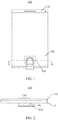
- FIG. 1 and FIG. 2 are schematic views showing a mobile terminal 100 to which an under-screen fingerprint identification apparatus is applicable.
- FIG. 1 is a schematic front view of a mobile terminal 100 to which an under-screen fingerprint identification apparatus is applicable
- FIG. 2 is a partial schematic cross-sectional structural view of the mobile terminal 100 shown in FIG. 1 taken along A'-A'.
- the mobile terminal 100 may include a display screen 11 and an under-screen fingerprint identification apparatus 10; and the display screen 11 has a display area 102, and the under-screen fingerprint identification apparatus 10 is disposed under the display screen 11.
- the display screen 11 may be a self-emitting display screen that employs a self-emitting display unit as a display pixel.
- the display screen 11 may be an organic light-emitting diode (Organic Light-Emitting Diode, OLED) display screen or a micro light-emitting diode (micro -LED) display screen.
- OLED Organic Light-Emitting Diode
- micro -LED micro light-emitting diode
- the display screen 11 may also be a liquid crystal display (Liquid Crystal Display, LCD) screen or other passive light-emitting display screens, which is not limited in the embodiments of the present application.
- the display screen 11 may be specifically a touch display screen, which may not only display a screen but also detect a touch or press operation of a user, thereby providing the user with a human-machine interaction interface.
- the mobile terminal 100 may include a touch sensor, and the touch sensor may be specifically a touch panel (Touch Panel, TP), which may be disposed on a surface of the display screen 11, or may be partially integrated or entirely integrated into an interior of the display screen 11 to form a touch display screen.
- Touch Panel Touch Panel
- the under-screen fingerprint identification apparatus 10 may be an optical under-screen fingerprint identification apparatus, which may include an optical fingerprint sensor with an optical sensing array, such as an optical fingerprint sensor; and the optical sensing array includes a plurality of optical sensing units, and an area where the optical sensing array is located is a fingerprint capturing area of the under-screen fingerprint identification apparatus 10, and the optical sensing units are used for capturing fingerprint characteristic information (such as fingerprint image information) of a user.
- an optical under-screen fingerprint identification apparatus which may include an optical fingerprint sensor with an optical sensing array, such as an optical fingerprint sensor; and the optical sensing array includes a plurality of optical sensing units, and an area where the optical sensing array is located is a fingerprint capturing area of the under-screen fingerprint identification apparatus 10, and the optical sensing units are used for capturing fingerprint characteristic information (such as fingerprint image information) of a user.
- the optical sensing array of the under-screen fingerprint identification apparatus 10 may be specifically a photo detector array (or referred to as a photodetector array) including a plurality of photo detectors or photodetectors distributed in an array, and the photo detectors or photodetectors may server as the optical sensing units as described above.
- a photo detector array or referred to as a photodetector array
- the photo detectors or photodetectors may server as the optical sensing units as described above.
- the under-screen fingerprint identification apparatus 10 may be disposed at least in a partial area under the display screen 11 such that the fingerprint capturing area (or sensing area) of the under-screen fingerprint identification apparatus 10 is at least partially located in the display area 102 of the display screen 11.
- the fingerprint capturing area 130 is located in the display area 102 of the display screen 11. Therefore, when a user needs to unlock the electronic device or perform other fingerprint verification, a fingerprint input operation can be implemented merely by pressing a finger on the fingerprint capturing area 130 in the display screen 11.
- the fingerprint capturing area 130 when a finger touches, is pressed against or approaches (collectively referred to as pressing for convenience of description) the fingerprint capturing area 130, light emitted by the display unit of the fingerprint capturing area 130 is reflected by the finger to form reflected light.
- the reflected light may carry fingerprint characteristic information of the finger of the user. For example, after the light is reflected by a fingerprint of a surface of the finger of the user, since the reflected light of a ridge of the fingerprint of the finger is different from that of a valley, the reflected light carries fingerprint information of the user.
- the reflected light is returned to the display screen 11, received by the photo detector array of the under-screen fingerprint identification apparatus 10 under the display screen 11, and converted into a corresponding electrical signal, i.e., a fingerprint detection signal.
- the mobile terminal 100 can acquire fingerprint information of the user based on the fingerprint detection signal, and can further perform fingerprint matching verification, thereby completing identity verification of the current user so as to confirm whether the user has permission to perform a corresponding operation
- a front surface of the mobile terminal 100 in the above structure does not need to reserve space to set a fingerprint button (such as a Home button), so that a full screen solution can be adopted. That is, the display area 102 of the display screen 11 can be substantially extended to the entire front surface of the mobile terminal 100.
- the fingerprint capturing area 130 shown in FIG. 1 is merely an example, and the embodiment of the present application is not limited thereto.
- the under-screen fingerprint identification apparatus 10 may also be disposed in an entire area under the display screen 11, so as to extend the fingerprint capturing area 130 to the entire display area 102 of the entire display screen 11, thereby implementing full screen fingerprint identification.
- the mobile terminal 100 may further include a protective cover 110, the protective cover 110 may be specifically a transparent cover such as a glass cover or a sapphire cover which is located on the display screen 11 and covers a front surface of the mobile terminal 100, and the surface of the protective cover 110 may also be provided with a protective layer. Therefore, in an embodiment of the present application, the so-called finger pressing the display screen 11 may actually refer to the finger pressing the cover 110 on the display screen 11 or covering a surface of the protective layer of the cover 110.
- a circuit board 150 may further be provided under the fingerprint identification apparatus 10, for example, a flexible circuit board (Flexible Printed Circuit, FPC).
- the fingerprint identification apparatus 10 may be soldered to the circuit board 150 through a pad, and achieve electrical interconnection and signal transmission with other peripheral circuits or other elements of the mobile terminal 100 through the circuit board 150.
- the fingerprint identification apparatus 10 may receive a control signal of a processing unit of the terminal device 100 through the circuit board 150, and may also output a fingerprint inspection signal to the processing unit, a control unit and the like of the terminal device 100 through the circuit board 150.
- the display screen 11 adopting the OLED display screen is taken as an example, the display screen 11 has OLED display units distributed in an array, and the under-screen fingerprint identification apparatus 10 can utilize an OLED display unit (i.e., an OLED light source) of the OLED display 11 located in the fingerprint capturing area 130 as an excitation light source for fingerprint detection and identification.
- an OLED display unit i.e., an OLED light source
- a backlight module is required as a light source of the display screen 11.
- an optical signal reflected by a human finger is very weak after image display of visible light emitted by the backlight module due to optical characteristics of the backlight module, the optical signal received by the fingerprint identification apparatus 10 could not realize fingerprint identification.
- An embodiment of the present application provides an under-screen fingerprint identification apparatus, which could achieve under-LED screen optical fingerprint identification.
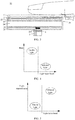
- FIG. 3 is a schematic structural view of an under-screen fingerprint identification apparatus according to an embodiment of the present application.
- the under-screen fingerprint identification apparatus 10 may be applied to an electronic device having a backlight module 20 and a display screen 11, and the under-screen fingerprint identification apparatus 10 may include: a fingerprint identification module 3, where the backlight module 20 is disposed under the display screen 11; the fingerprint identification module 3 is disposed under the backlight module 20; and the fingerprint identification module 3 is configured to receive an infrared light signal passing through the backlight module 20 that is emitted by an infrared light source 5 and illuminates a human finger, and the infrared light signal is used to detect fingerprint information of the finger; where a haze of the infrared light signal passes through the backlight module 20 is less than a haze of visible light for displaying an image passes through the backlight module 20.
- the infrared light signal for fingerprint identification received by the fingerprint identification module 3 may be an optical signal that the human finger performs optical processing on an infrared light signal emitted by the infrared light source.
- the optical signal received by the fingerprint identification module 3 may be either an infrared light signal that is reflected by the human finger and passes through the backlight module 20, or an infrared light signal that is diffused by the human finger and passes through the backlight module 20. This is not limited in the embodiment of the present application.
- the infrared light signal emitted by the infrared light source 5 may be used for fingerprint identification, and the infrared light signal is invisible light.
- an optical signal used for image display by the display screen 11 is a visible light source
- the visible light source may be any light source located behind a liquid crystal display (LCD).
- the visible light source may be an electroluminescent (EL) backlight source, a minitype cold cathode fluorescent lamp (CCFL) or an LED backlight source.
- EL electroluminescent
- CCFL minitype cold cathode fluorescent lamp
- the optical signal for fingerprint identification is the infrared light signal emitted by the infrared light source 5
- the optical signal for displaying an image is a visible light signal emitted by the visible light source. Therefore, the under-screen identification apparatus 10 of the embodiment of the present application could not only avoid interference of the visible light to fingerprint identification, but also have no influence on a displayed image since the infrared light signal is invisible light.
- a haze of the infrared light signal passes through the backlight module 20 is less than a haze of visible light for displaying an image passes through the backlight module 20, not only the modulation of a visible light signal could be implemented, but also the loss of the infrared light signal in light path transmission could be effectively reduced.
- light transmittance of the infrared light signal passes through the backlight module is greater than light transmittance of the visible light passes through the backlight module.
- reflectivity of the infrared light signal passes through the backlight module is less than reflectivity of the visible light passes through the backlight module.
- the infrared light source 5 may be fixed under the display screen 11, and the fingerprint identification module 3 may also be fixed under the display screen 11.
- the infrared light source 5 may be pasted under the display screen 11 by an optical adhesive 4.
- the fingerprint identification module 3 may also be mechanically fixed under the display screen 11.
- the fingerprint identification module 3 may be fixed under the display screen 11 by means of threaded connection.
- the optical adhesive 4 may be any one of optical liquid glue and an optical solid adhesive.
- the optical adhesive 4 and the display screen 11 have the same or similar optical reflective indexes, and thus a utilization ratio of the infrared light signal emitted by the infrared light source 5 could be increased as much as possible.
- the at least one infrared light source 5 is integrated in the backlight module 20.
- the at least one infrared light source 5 and a light source in the backlight module 20 for displaying an image are integrally disposed.
- the at least one infrared light source 5 and a light source in the backlight module 20 for displaying an image are integrally disposed in parallel.
- the at least one infrared light source 5 and a light source in the backlight module 20 for displaying an image may are integrally disposed in a non-parallel manner. This is not limited in the embodiment of the present application.
- the backlight module 20 may include a composite film 21, a brightness enhancement film 22, a diffusion film 23, a light guide plate24, and a reflection film 25 and a steel plate 26.
- the visible light emitted by the visible light source is transmitted to the diffusion film 23 after passing through the light guide plate 24, light diffused by the diffusion film 23 is transmitted to the brightness enhancement film 22, the brightness enhancement film 22 is used to gain the received optical signal, and transmit the gained optical signal to the composite film 21, and the composite film 21 receives the optical signal for further gaining the received optical signal and transmits the gained optical signal to the display screen 11 for image display.
- the backlight module 20 shown in FIG. 3 is merely an example, and the embodiment of the present application is not limited thereto.
- the backlight module 20 may not include the steel sheet 26 and/or the reflection film 25.
- the light guide plate 24 may use a high-tech material with extremely high reflectivity and no light absorption, and light guide points are printed on the bottom of an optical-level acrylic plate by technologies such as laser engraving technology or ultra-violet ray (Ultra-Violet Ray, UV) screen printing technology.
- the optical-level acrylic plate is used to absorb light emitted from a lamp to stay on a surface of the optical-level acrylic plate, when the light illuminates the respective light guide points, reflected light may be diffused at various angles, then break a reflection condition, and be out of the front surface of the light guide plate.
- the function of the light guide plate 24 is to guide a scattering direction of light to increase brightness of a panel and ensure uniformity of the brightness of the panel.
- the visible light source may be located at a side of the light guide plate 24, and light emitted by the visible light source is introduced into an interior of the light guide plate 24 by reflection. When the light is incident on a diffusion point, reflected light may be diffused at various angles, and then be out of the front surface of the light guide plate 24.
- diffusion points with various dense and different size may be used to cause the light guide plate 24 to uniformly emit light.
- a haze of the infrared light signal passes through the diffusion layer 23 is less than a haze of the visible light for displaying an image passes through the diffusion layer 23.
- light transmittance of the infrared light signal passes through the diffusion layer 23 is greater than light transmittance of the visible light passes through the diffusion layer 23.
- the diffusion plate 23 can not only improve brightness of the front surface of the display screen 11 such that distribution of visible light is more uniform, but also ensure that a user would not see reflection points from the front side. Moreover, since the haze of the infrared light signal passes through the diffusion layer 23 is less than the haze of the visible light for displaying an image passes through the diffusion layer 23, and the light transmittance of the infrared light signal passes through the diffusion layer 23 is greater than the light transmittance of the visible light passes through the diffusion layer 23, the loss of the infrared light signal in optical transmission could be effectively reduced.
- the direction of the visible light signal could be effectively corrected by the brightness enhancement film 22 to achieve an effect of converging light and improve the brightness of the front surface of the display screen 11.
- the brightness enhancement film 22 may be placed between the diffusion layer 23 and the display screen 11.
- the brightness enhancement film 22 may be implemented by a prismatic film.
- the prism film may converge the light that is out of the diffusion sheet 23 and diffused uniformly at various angles onto an axial angle by improving angular distribution of the visible light signal for displaying an image, that is, a front view angle, that is, axial brightness is increased without increasing the total outgoing light flux.
- the prism film may select incident light to pass light that meets a convergence light angle, and unqualified light is reflected back to the diffusion sheet 23, diffused in the diffusion sheet 23 and then returned to the prism film until it meets an emergence condition.
- the brightness enhancement film 22 may be implemented by a reflective polarizer.
- the reflective polarizer is different from the prism, the reflective polarizer may perform selective cyclic brightening according to different polarization directions of visible light signal, the reflective polarizer could accurately reflect 100% of polarized light parallel to the optical axis direction thereof, and polarized light in another orthogonal direction may normally penetrate the reflective polarizer.
- the function of the reflection plate 25 in the embodiment of the present application in image display is to reflect light leaking from the bottom surface of the light guide plate 24 back into the light guide plate to improve efficiency of use of light.
- light transmittance of the infrared light signal passes through the reflection layer 25 is greater than light transmittance of the visible light passes through the reflection layer 25.
- the reflection layer 25 since the light transmittance of the infrared light signal passes through the reflection layer 25 is greater than the light transmittance of the visible light passes through the reflection layer 25, the reflection layer 25 could not only improve efficiency of use of light, but also reduce the loss of the infrared light signal in a transmission path caused by the reflection layer 25 and improve fingerprint identification quality.
- the steel plate 26 is provided with a hole 261, and the fingerprint identification module 3 is disposed under the hole 261 and configured to receive an infrared light signal passing through the hole 261 that is emitted by the infrared light source 5 and illuminates the human finger.
- the visible light signal may be prevented from being transmitted in a direction opposite to the display screen 11 as much as possible, the damage of the backlight module 20 due to an external impact is avoided, and the energy loss of the infrared light signal for fingerprint identification as it passes through the steel plate 26 could be effectively reduced.
- the under-screen fingerprint identification apparatus 10 further includes a visible light filter 6, and the visible light filter 6 may be disposed between the backlight module 20 and the fingerprint identification module 3. Thereby, visible light transmitted to the visible light filter 6 may be filtered, and the identification quality of the fingerprint identification module 3 could be further improved.
- the visible light filter 6 may be specifically configured to filter out visible light wavelengths, for example, visible light for image display.
- the filter 109 may specifically include one or more optical filters, the one or more optical filters may be configured as, for example, bandpass filters to filter out light emitted by a visible light source while not filtering out an infrared light signal.
- the one or more optical filters can be implemented as, for example, optical filter coatings formed on one or more continuous interfaces or one or more discrete interfaces.
- the visible light filter 6 can be fabricated on a surface of any optical component or along an optical path to the fingerprint identification module 3 from reflected light formed by reflection of a finger.
- FIG. 3 is only an example in which the visible light filter 6 is disposed between the steel plate 26 and the fingerprint identification module 3, and the present application is not limited thereto.
- the visible light filter 6 may be attached to a bottom surface of the display screen 11, an upper surface of the steel plate 26, an interior of the fingerprint identification module 3, or the like.
- the under-screen fingerprint identification apparatus 10 includes: at least one infrared light source 5, where each infrared light source 5 is disposed under the display screen.
- the under-screen fingerprint identification apparatus 10 includes a plurality of infrared light sources 5, the plurality of infrared light sources 5 are symmetrically arranged with the fingerprint identification module 3 as a center, or the plurality of infrared light sources are symmetrically arranged based on an axis of symmetry, and the axis of symmetry is a line that passes through the fingerprint identification module 3 and is parallel to the display screen 11.
- the under-screen fingerprint identification apparatus 10 may include two infrared light sources 5, and projection formed by the two infrared light sources 5 and the fingerprint identification module 3 on the display screen 11 is an isosceles triangle.
- the under-screen fingerprint identification apparatus 10 may include three infrared light sources 5, and projection formed by the three infrared light sources 5 and the fingerprint identification module 3 on the display screen 11 is an isosceles triangle, where the three infrared light sources 5 are arranged on a base of the isosceles triangle and symmetrically arranged.
- the under-screen fingerprint identification apparatus 10 may include four infrared light sources 5, and projection formed by the four infrared light sources 5 on the display screen 11 is a rectangle, and the fingerprint identification module 3 is located at a center of the rectangle.
- the under-screen fingerprint identification apparatus 10 may include a strip-like light source
- the strip-like light source may include a plurality of infrared light sources 5
- projection formed by the plurality of infrared light sources 5 and the fingerprint identification module 3 on the display screen 11 is an isosceles triangle, where the plurality of infrared light sources 5 are arranged on a base of the isosceles triangle and symmetrically arranged.
- the infrared light source 5 is obliquely attached to a lower surface of the display screen 11.
- a utilization ratio of the infrared light signal emitted by the infrared light source 5 in a fingerprint identification process could be effectively improved.
- the infrared light source 5 is flatly attached to a lower surface of the display screen 11.
- an attaching process could be effectively simplified, thereby improving a yield in a product assembly process.
- the infrared light signal emitted by the infrared light source 5 is used for fingerprint identification.
- the infrared light in the environment may be transmitted to the fingerprint identification module 3 such that a part of an infrared light signal received by the fingerprint identification module 3 may not carry fingerprint information, thereby reducing identification efficiency of the fingerprint identification module 3.
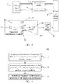
- FIG. 13 is another schematic block diagram of an under-screen fingerprint identification apparatus according to an embodiment of the present application.
- the under-screen fingerprint identification apparatus 10 may further include:
- the infrared light signal emitted by the infrared light source 5 is distinguished from the an infrared light signal in the environment.
- the infrared light source 5 may perform a turnon or turnoff operation by using a certain specific modulation frequency. Since most of light in the environment may be regarded as an optical signal with a very small frequency or a very slow frequency change, the influence of strong light in the environment may be well shielded by using a method of modulation.
- the signal captured by the fingerprint identification module 3 also includes the relevant modulation frequency.
- the signal may be restored by the demodulation circuit 9 and then transmitted to the control processing unit 8 to facilitate fingerprint identification by the control processing unit 8.
- a capturing area of the fingerprint identification module 3 is located in the display screen 11, and the capturing area may include a plurality of capturing blocks.
- the capturing area may include a capturing block 31, a capturing block 32, a capturing block 33, a capturing block34 and a capturing block 35.
- an embodiment of the present application further provides a backlight module for under-screen fingerprint identification, for example, the backlight module 20 shown in FIG. 3 .
- the backlight module 20 is configured to transmit an infrared light signal that is emitted by an infrared light source 5 and illuminates a human finger to a fingerprint identification module 3, and the infrared light signal is used to detect fingerprint information of the finger; where the backlight module 20 has a smaller haze for the infrared light signal than for visible light for image display.
- the backlight module 20 may include a diffusion layer 23, where a haze of the infrared light signal passes through the diffusion layer 23 is less than a haze of the visible light passes through the diffusion layer 23.
- light transmittance of the infrared light signal passes through the diffusion layer 23 is greater than light transmittance of the visible light passes through the diffusion layer 23.
- the backlight module may include a reflection layer 25, where light transmittance of the infrared light signal passes through the reflection layer 25 is greater than light transmittance of the visible light passes through the reflection layer 25.
- the backlight module 20 may include a steel plate 26, where the steel plate 26 is provided with a hole 261, and the fingerprint identification module 3 is disposed under the hole 261 and configured to receive an infrared light signal passing through the hole 261 that is emitted by the infrared light source 5 and illuminates the human finger.
- An embodiment of the present application further provides an electronic device, and the electronic device may include the under-screen fingerprint identification apparatus described above, for example, the under-screen fingerprint identification apparatus 10 shown in FIG. 10 .
- the under-screen fingerprint identification apparatus 10 may further include a fingerprint identification module 3
- the electronic device may further include: the backlight module described above, for example, the backlight module 20 shown in FIG. 3 , and the fingerprint identification module 3 is disposed under the backlight module 20.
- An embodiment of the present application further provides an electronic device, and the electronic device may include the backlight module described above, for example, the backlight module 20 shown in FIG. 3 .
- the electronic device may further include: a fingerprint identification module 3, an infrared light source 5 and a display screen 11.
- the backlight module 20 and the infrared light source are disposed under the display screen 11, and the fingerprint identification module 3 is disposed under the backlight module 20; and the fingerprint identification module 3 is configured to receive an infrared light signal passing through the backlight module 20 that is emitted by the infrared light source 5 and illuminates a human finger, and the infrared light signal is used to detect fingerprint information of the finger.
- the under-screen fingerprint identification apparatus 10 and the backlight module 20 of the embodiment of the present application are described in detail above, and a specific fingerprint identification method based on a case that the capturing area of the fingerprint identification module includes a plurality of capturing blocks will be described below.
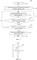
- FIG. 14 is a schematic flowchart of a method 200 for fingerprint identification according to an embodiment of the present application.
- the method 200 may be performed by the mobile terminal 100 described in FIG. 1 or FIG. 2 , the fingerprint identification apparatus 10 shown in FIG. 3 , or the fingerprint identification module 3 in the fingerprint identification apparatus 10.
- the fingerprint identification apparatus 10 or the terminal device 100 is triggered to perform the method 200 after the fingerprint identification module 3 is initialized by a user, and the method 200 includes some or all of the following contents:
- a capturing area of the fingerprint identification module 3 that is located in the display screen 11 may include a plurality of capturing blocks.
- the capturing area may include a capturing block 31, a capturing block 32, a capturing block 33, a capturing block34 and a capturing block 35.
- the fingerprint identification apparatus 10 may determine whether to trigger the fingerprint identification module 3 to perform a fingerprint capturing operation based on whether the light intensity of the capturing block 31, the capturing block 32, the capturing block 33, the capturing block34 and the capturing block 35 satisfies a preset condition.
- the fingerprint identification apparatus 10 acquires the fingerprint information when a variation of the light intensity is greater than or equal to a preset threshold.
- the preset threshold may be a preset light intensity change threshold.
- the fingerprint identification apparatus 10 acquires the fingerprint information when an intensity value of the light intensity is greater than or equal to a preset intensity threshold.
- intensity thresholds may be set in different scenes. For example, a greater intensity threshold may be set in a scene with strong ambient light (such as day). For another example, a less intensity threshold may be set in a scene with weak ambient light (such as night or cloudy day). Accuracy of the fingerprint information acquired by the fingerprint identification apparatus 10 triggered by the intensity value of the light intensity could by effectively improved by the foregoing technical solution.
- the fingerprint identification apparatus 10 acquires the fingerprint information when the intensity value or the variation of the light intensity is within a preset range.
- the preset threshold of the embodiment of the present application is a triggering threshold of the fingerprint identification apparatus 10 for performing a fingerprint identification operation.
- the preset threshold is merely an example, and the embodiment of the present application is not limited thereto.
- the triggering threshold of the fingerprint identification apparatus may also be a threshold dynamically adjusted based on the preset threshold.
- the light intensity is acquired through a photoelectric sensor.
- the photoelectric sensor may be a photodiode (PD).
- the fingerprint identification apparatus 10 before the fingerprint identification apparatus 10 acquires the light intensity of the capturing blocks in the capturing area located in the display screen, the fingerprint identification apparatus 10 acquires an infrared light signal reflected by a human finger; and the fingerprint identification apparatus 10 adjusts a detection range of the photoelectric sensor when the infrared light signal is not within the detection range of the photoelectric sensor.
- an output signal of the photoelectric sensor ranges from 0 to 1 A.
- the fingerprint identification apparatus 10 may adjust the range of the output signal of the photoelectric sensor to 0 ⁇ 100mA. In the embodiment of the present application, by adjusting the detection range of the photoelectric sensor, detection accuracy of the photoelectric sensor could be effectively improved.
- the photoelectric sensor is further configured to detect fingerprint information or heart rate information.
- the embodiment of the present application is described by an example that when the light intensity of the capturing blocks satisfies the present condition, the fingerprint identification apparatus 10 is triggered to acquire the fingerprint information of the capturing area, and the embodiment of the present is not limited thereto.
- whether to trigger the fingerprint identification apparatus 10 to acquire the fingerprint information of the capturing area may be determined in combination with other conditions.
- the following describes an implementation manner in which the fingerprint identification apparatus 10 triggers a capturing operation of fingerprint data in combination with other conditions.
- the fingerprint identification apparatus 10 acquires the fingerprint information when the light intensity satisfies the preset condition and it is determined that the display screen is not shielded.
- the fingerprint identification apparatus 10 determines whether the display screen is shielded through an illuminance sensor.
- FIG. 15 is a schematic flowchart of a method 300 for fingerprint identification according to an embodiment of the present application.
- the method 300 may be performed by the mobile terminal 100 described in FIG. 1 or FIG. 2 , the under-screen fingerprint identification apparatus 10 shown in FIG. 3 , or the fingerprint identification module 3 in the fingerprint identification apparatus 10.
- the method 300 includes some or all of the following contents:
- the fingerprint identification apparatus 10 acquires the fingerprint information when the light intensity satisfies the preset condition and a press force with which a human finger is pressed against the capturing blocks is greater than or equal to a pressure threshold.
- a pressure value may be generated by pressing the display screen of a fingerprint capturing area 130 by a user, a capturing operation of fingerprint data is triggered when the pressure value is greater than or equal to the pressure threshold, and in contrast, the capturing operation of fingerprint data is not triggered when the pressure value is less than the triggering threshold.
- the pressure threshold may be a preset threshold, or may be a threshold determined before the fingerprint identification apparatus 10 captures the fingerprint data.
- the fingerprint identification apparatus 10 may acquire the press force with which the human finger is pressed against the capturing blocks through a pressure sensor.
- the pressure sensor includes, but is not limited to, a capacitive pressure sensor or a resistive pressure sensor.
- the capacitive pressure sensor may also be referred to as a "pressure-capacitance" sensor, the principle of which is shown in FIG 16 .
- pressure-capacitance sensor
- the pressure When pressure is applied to a polar plate 312, the pressure causes spacing of a capacitors 321 between the two polar plates 311 and 312 to change, thereby changing a capacitance value. Different pressures produce different capacitance value changes, a variation of the capacitance value is converted into an electrical signal, and the corresponding pressure may be detected by detecting the change of the signal by the detecting chip.
- the resistive pressure sensor may also be referred to as a "piezoresistive" sensor, the principle of which is shown in FIG. 17 .
- the resistive pressure sensor 332 is disposed on a certain force receiving surface to be detected, and the force bearing body 331 is deformed by force to squeeze or stretch the resistive pressure sensor 332 so that its resistance value changes accordingly. Different pressures produce different resistance value changes, and the corresponding force could be detected by detecting the change of the resistance value by the detecting chip.
- a bridge resistance pressure sensor which is capable of suppressing hardware-level temperature drift.
- IN+ represents a positive input of a data signal
- IN- represents a negative input of the data signal
- VDD represents an input voltage.
- the fingerprint identification apparatus 10 acquires the fingerprint information when the light intensity satisfies the preset condition and an object pressed against the capturing blocks is a living body.
- heart rate information may be acquired by a living body detection unit; and whether the object pressed against the capturing blocks is a living body is determined according to the heart rate information.
- FIG. 19 is a schematic diagram of an under-screen fingerprint identification apparatus having a living body detection unit according to an embodiment of the present application.
- the under-screen fingerprint identification apparatus may include: a fingerprint identification module 3, where the fingerprint identification module 3 may include a living body detection unit 36.
- the living body detection unit 36 is configured to acquire heart rate information, and determine whether the object pressed against the capturing blocks is a living body according to the heart rate information.
- the living body detection unit 36 may include at least one photoelectric sensor.
- the under-screen fingerprint identification apparatus may further include: a range adjustment unit 93 configured to adjust the detection range of the photoelectric sensor.
- the under-screen fingerprint identification apparatus may further include: an amplification filter circuit 91 and an analog to digital converter circuit 92.
- the biometric detection unit 36 converts the optical signal into an electrical signal and transmits the electrical signal to the demodulation circuit 9, the demodulation circuit demodulates the electric signal and transmits the demodulated electrical signal to the amplification filter circuit 91, the demodulated electrical signal is transmitted to the analog to digital converter circuit 92 via the amplification filter circuit 91 so that the analog to digital converter circuit 92 transmits a converted digital signal to the control processing unit 8 for fingerprint identification by the control processing unit 8.
- FIG. 20 is a schematic flowchart of a method 400 for fingerprint identification according to an embodiment of the present application.
- the method 400 may be performed by the mobile terminal 100 described in FIG. 1 or FIG. 2 , the under-screen fingerprint identification apparatus 10 shown in FIG. 3 , or the fingerprint identification module 3 in the fingerprint identification apparatus 10.
- the method 400 includes some or all of the following contents: as shown in FIG. 20 , the method 400 for identifying a fingerprint may include:
- the process that the under-screen fingerprint identification apparatus 10 acquires the infrared light signal reflected by the human finger may be specifically performed by the living body detection unit 36 shown in the drawing. Further, the living body detection unit 36 is further configured to determine whether the object pressed against the display screen is a living body.
- the embodiment of the present invention is not limited thereto.
- the principle of triggering the under-screen fingerprint identification apparatus 10 to acquire the fingerprint information of the capturing area in combination with the photoelectric sensor, the pressure sensor, the illuminance sensor and the living body detection unit is described in detail above.
- the under-screen fingerprint identification apparatus 10 when a certain condition is satisfied, the under-screen fingerprint identification apparatus 10 is triggered to acquire the fingerprint information of the capturing area in combination with the photoelectric sensor, the pressure sensor, the illuminance sensor and the living body detection unit.
- the under-screen fingerprint identification apparatus 10 is triggered to acquire the light intensity.
- the under-screen fingerprint identification apparatus 10 acquires the light intensity when it is determined that a display interface of the display screen is a fingerprint verification interface.
- the under-screen fingerprint identification apparatus 10 needs to determine whether the display interface of the display screen is a fingerprint verification interface, and the under-screen fingerprint identification apparatus 10 acquires the light intensity of the capturing blocks in the capturing area located in the display screen when it is determined that the display interface of the display screen is a fingerprint verification interface.
- the fingerprint verification interface includes an identification of the capturing area so that the user presses the capturing area in the display screen according to the identification.
- the identification may be a fingerprint image or an another form of an image formed at the capturing position within the display screen.
- the display interface of the display screen is the fingerprint verification interface, the user may be guided to perform fingerprint capturing.
- the display interface of the display screen is switched to the fingerprint verification interface.
- the display interface of the display screen is switched to the fingerprint verification interface.
- the process of switching the display interface to the fingerprint verification interface in the embodiment of the present application may be performed by the terminal device 100, may be performed by the fingerprint identification apparatus 10, or may be performed by the fingerprint identification module 3 in the fingerprint identification apparatus 10, which is not specifically limited in this embodiment of the present application.
- the living body detection unit 36 is only configured to determine whether a finger is pressed by acquiring an infrared light signal reflected by the human finger, that is, whether light intensity of the infrared light signal satisfies a preset condition. That is, the living body detection unit 36 may not be used for living body identification after 443.
- the under-screen fingerprint identification apparatus may further executes a target application corresponding to a first press order according to the first press order in which the human finger is pressed against the plurality of blocks and mapping relationship information, where the mapping relationship information includes a correspondence between at least one press order and at least one application, and the at least one press order includes the first press order.
- the first press order of the embodiment of the present application may be an order in which the human finger is pressed against the plurality of blocks, or may be an order in which another object (such as a stylus) is pressed against the plurality of blocks. This is not limited in the embodiment of the present application.
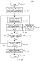
- FIG. 22 is a schematic flowchart of a method 500 of executing an application by a fingerprint identification apparatus according to a first press order according to an embodiment of the present application.
- the method 500 may be performed by the mobile terminal 100 described in FIG. 1 or FIG. 2 , or may be performed by the control processing unit 8 shown in FIG. 13 or FIG. 19 .
- the method 500 includes some or all of the following contents:
- any combination may be made between various embodiments of the present application without departing from the idea of the present application, and it should also be regarded as the disclosure of the present application.
- FIG. 23 is a schematic block diagram of an under-screen fingerprint identification apparatus 600 according to an embodiment of the present application.
- the under-screen fingerprint identification apparatus 600 may include: an acquisition unit 610 configured to:
- the acquisition unit 610 is specifically configured to: acquire the fingerprint information when a variation of the light intensity is greater than or equal to a preset threshold.
- the acquisition unit 610 is specifically configured to: acquire the light intensity through a photoelectric sensor.
- the under-screen fingerprint identification apparatus further includes: a range adjustment unit configured to: acquire, before the acquisition unit 610 acquires the light intensity, an infrared light signal reflected by a human finger; and adjust a detection range of the photoelectric sensor when the infrared light signal is not within the detection range of the photoelectric sensor.
- a range adjustment unit configured to: acquire, before the acquisition unit 610 acquires the light intensity, an infrared light signal reflected by a human finger; and adjust a detection range of the photoelectric sensor when the infrared light signal is not within the detection range of the photoelectric sensor.
- the photoelectric sensor is further configured to detect fingerprint information or heart rate information.
- the acquisition unit 610 is specifically configured to: acquire the fingerprint information when the light intensity satisfies the preset condition and a press force with which a human finger is pressed against the capturing blocks is greater than or equal to a pressure threshold.
- the under-screen fingerprint identification apparatus further includes: a pressure sensor configured to acquire, before the acquisition unit 610 acquires the fingerprint information, the press force with which the human finger is pressed against the capturing blocks.
- the acquisition unit 610 is further configured to: acquire the fingerprint information when the light intensity satisfies the preset condition and it is determined that the display screen is not shielded.
- the under-screen fingerprint identification apparatus further includes: an illuminance sensor configured to determine, before the acquisition unit 610 acquires the fingerprint information, whether the display screen is shielded.
- the acquisition unit 610 is specifically configured to: acquire the fingerprint information when the light intensity satisfies the preset condition and an object pressed against the capturing blocks is a living body.
- the under-screen fingerprint identification apparatus further includes: a living body detection unit configured to: acquire heart rate information before the acquisition unit 610 acquires the fingerprint information; and determine whether the object pressed against the capturing blocks is a living body according to the heart rate information.
- a living body detection unit configured to: acquire heart rate information before the acquisition unit 610 acquires the fingerprint information; and determine whether the object pressed against the capturing blocks is a living body according to the heart rate information.
- the capturing blocks include a plurality of blocks.
- the under-screen fingerprint identification apparatus 600 may further include: an execution unit configured to execute a target application corresponding to a first press order according to the first press order in which a human finger is pressed against the plurality of blocks and mapping relationship information, where the mapping relationship information includes a correspondence between at least one press order and at least one application, and the at least one press order includes the first press order.
- the acquisition unit 610 is specifically configured to: acquire the light intensity when it is determined that a display interface of the display screen is switched to a fingerprint verification interface, where the fingerprint verification interface includes an identification of the capturing area.
- the under-screen fingerprint identification apparatus 600 may further include: a switching unit configured to switch, after a user presses a power button, the display interface of the display screen to the fingerprint verification interface.
- the under-screen fingerprint identification apparatus 600 may further include: a switching unit configured to switch, after a user touches the display screen, the display interface of the display screen to the fingerprint verification interface.
- the under-screen fingerprint identification apparatus 600 shown in FIS. 23 may correspond to a corresponding subject for executing the method of the embodiment of the present application, the foregoing and other operations and/or functions of the respective units in the under-screen fingerprint identification apparatus 600 are receptively to implement the corresponding flow of the various methods in FIG. 14 , FIG. 15 , FIG. 20 to FIG. 22 , which is not repeatedly described here for brevity.
- the apparatus for fingerprint identification according to the embodiment of the present application is described above with reference to FIG. 23 from the perspective of a functional module. It should be understood that the functional module may be implemented by hardware, by an instruction in a form of software, or by a combination of hardware and software modules.
- steps of the method embodiments in the embodiments of the present application may be completed by using an integrated logical circuit of hardware in the processor and/or an instruction in a form of software. Steps of the methods disclosed in the embodiments of the present application may be directly executed and completed by using a hardware decoding processor, or may be executed and completed by using a combination of hardware and software modules in the decoding processor.
- the software module may be located in a mature storage medium in the art, such as a random access memory, a flash memory, a read-only memory, a programmable read-only memory, an electrically-erasable programmable memory, or a register.
- the storage medium is located in the memory, and the processor reads information in the memory and completes the steps of the foregoing method embodiments in combination with hardware of the processor.
- the acquisition unit 610 shown in FIG. 23 may be implemented by a fingerprint identification module, and the fingerprint identification unit 620 shown in FIG. 23 may be implemented by a processor.
- FIG. 24 is a schematic structural diagram of an under-screen fingerprint identification apparatus 700 according to an embodiment of the present application.
- the under-screen fingerprint identification apparatus 700 shown in FIG. 24 may include a processor 710, the processor 710 may call a computer program from a memory and run it to implement the method in the embodiment of the present application.
- the under-screen fingerprint identification apparatus 700 may further include a memory 720.
- the memory 720 may be configured to store indication information, and may further be configured to store codes and instructions executed by the processor 710.
- the processor 710 may call a computer program from the memory 720 and run it to implement the method in the embodiment of the present application.
- the memory 720 may be a separate device independent of the processor 710 or may be integrated in the processor 710.
- the under-screen fingerprint identification apparatus 700 may further include a display screen 740 for displaying information to a user.
- the under-screen fingerprint identification apparatus 700 may further include a fingerprint identification module 730, where the fingerprint identification module 730 may be configured to acquire light intensity of capturing blocks, and when the light intensity is greater than a preset condition, the fingerprint identification module 730 acquires fingerprint information of a capturing area so that the processor 710 performs fingerprint identification according to the fingerprint information.
- the fingerprint identification module 730 may be configured to acquire light intensity of capturing blocks, and when the light intensity is greater than a preset condition, the fingerprint identification module 730 acquires fingerprint information of a capturing area so that the processor 710 performs fingerprint identification according to the fingerprint information.
- the under-screen fingerprint identification apparatus 700 may correspond to the under-screen fingerprint identification apparatus 600 in the embodiment of the present application, and may correspond to a corresponding subject for executing the methods according to the various method embodiments in FIG. 14 , FIG. 15 , FIG. 20 to FIG. 22 of the present application, which is not repeatedly described here for brevity.
- the various components in the under-screen fingerprinting identification apparatus 700 are connected by a bus system, where the bus system includes a power bus, a control bus and a status signal bus in addition to a data bus.
- processor described in the embodiment of the present application may be an integrated circuit chip with signal processing capability, and can implement and execute the methods, the steps, and the logical block diagrams disclosed in the embodiments of the present application.
- the foregoing processor may be a general purpose processor, a digital signal processor (digital signal processor, DSP), an application specific integrated circuit (application specific integrated circuit, ASIC), a field programmable gate array (field programmable gate array, FPGA) or another programmable logic device, a transistor logic device, a discrete hardware component, or the like.
- DSP digital signal processor
- ASIC application specific integrated circuit
- FPGA field programmable gate array
- the general purpose processor may be a microprocessor or the processor may be any conventional processor or the like.
- the memory described in the embodiments of the present application may be a volatile memory or a nonvolatile memory, or may include both volatile and nonvolatile memory.
- the non-volatile memory may be a read-only memory (read-only memory, ROM), a programmable read-only memory (programmable ROM, PROM), an erasable programmable read-only memory (erasable PROM, EPROM), an electrically erasable programmable read-only memory (electrically EPROM, EEPROM), or a flash memory.
- the volatile memory may be a random access memory (random access memory, RAM) and used as an external cache.
- the memory in the embodiment of the present application may further be a static random access memory (static RAM, SRAM), a dynamic random access memory (dynamic RAM, DRAM), a synchronous dynamic random access memory (synchronous DRAM, SDRAM), a double data rate synchronous dynamic random access memory (double data rate SDRAM, DDR SDRAM), an enhanced synchronous dynamic random access memory (enhanced SDRAM, ESDRAM), a synch link dynamic random access memory (synch link DRAM, SLDRAM), a direct rambus random access memory (Direct Rambus RAM, DR RAM), and the like.
- static random access memory static random access memory
- DRAM dynamic random access memory
- DRAM dynamic random access memory
- SDRAM synchronous dynamic random access memory
- double data rate SDRAM double data rate SDRAM
- DDR SDRAM double data rate SDRAM
- ESDRAM enhanced synchronous dynamic random access memory
- synch link dynamic random access memory synch link dynamic random access memory
- SLDRAM direct rambus random access memory
- Direct Rambus RAM Direct Rambus RAM, DR RAM
- FIG. 25 is a schematic structural diagram of an electronic device (for example, a touch screen cell phone) 800 to which an embodiment of the present application is applied.
- the electronic device 800 may include: a processor 810, a memory 820 and a touch display screen 830.
- the touch display screen 830 includes a pressure sensor 831 for sensing a magnitude of pressure of a touch input signal on the touch display screen 830.
- the processor 810 is configured to receive a pressure signal sensed by the pressure sensor 831 and to process the pressure signal, for example, trigger a certain application in the mobile terminal 100 based on the pressure signal.
- the electronic device 800 may further include a fingerprint identification module 880, where the fingerprint identification module 880 is configured to acquire light intensity of capturing blocks, and acquire fingerprint information of a capturing area when the light intensity satisfies a preset condition.
- the fingerprint identification module 880 is configured to acquire light intensity of capturing blocks, and acquire fingerprint information of a capturing area when the light intensity satisfies a preset condition.
- the electronic device 800 may further include an illuminance sensor 890 configured to determine whether the touch display screen 830 is shielded.
- the electronic device may further include other components, such as an audio circuit 840, a power supply 850, a WiFi module 860, a radio frequency circuit 870 and the like as shown in FIG. 1
- the power source 850 may include a visible light source and an infrared light source, where visible light emitted by the visible light source is used to display an image, and infrared light emitted by the infrared light source is used for fingerprint identification.
- the integrated unit is implemented in the form of the software functional unit and is sold or used as an independent product, it may be stored in a computer readable storage medium.
- the technical solutions of the embodiments of the present application substantially, or the part of the present disclosure making contribution to the prior art, or a part of the technical solutions may be embodied in the form of a software product, and the computer software product is stored in a storage medium, which includes multiple instructions enabling computer equipment (which may be a personal computer, a server, network equipment or the like) to execute all of or part of the steps in the methods of the embodiments of the present application.
- the storage medium includes: various media that may store program codes, such as a U-disk, a removable hard disk, a read-only memory, a random access memory, a magnetic disk, a compact disk, and so on.
- the division of the units or modules or components in the apparatus embodiments described above is only a logic function division, other division modes may be adopted in practice, e.g., multiple units or modules or components may be combined or integrated in another system, or some units or modules or components may be omitted or be not executed.
- the units/modules/components described as separate/display components may be or may not be physically separated, namely, may be located in one place, or may be distributed on a plurality of network units. Part of or all of the units/modules/components here may be selected according to a practical need to achieve the objectives of the embodiments of the present application.
Landscapes
- Engineering & Computer Science (AREA)
- Physics & Mathematics (AREA)
- General Physics & Mathematics (AREA)
- Theoretical Computer Science (AREA)
- Multimedia (AREA)
- Human Computer Interaction (AREA)
- Optics & Photonics (AREA)
- Health & Medical Sciences (AREA)
- Toxicology (AREA)
- Image Input (AREA)
- Measurement Of The Respiration, Hearing Ability, Form, And Blood Characteristics Of Living Organisms (AREA)
Abstract
Description
- Embodiments of the present application relate to the field of under-screen fingerprint identification, and more particularly, to a backlight module, an under-screen fingerprint identification method, an apparatus and an electronic device.
- At present, under-screen fingerprint identification is mainly applied to an Organic Light-Emitting Diode (Organic Light-Emitting Diode, OLED) screen, and the principle is that an under-OLED screen fingerprint identification module receives reflected light formed by reflection by a finger that is emitted from the OLED screen itself to detect a fingerprint by using light transmission characteristics the OLED screen possesses.
- However, since a light emitting principle and a specific structure of a liquid crystal display (Liquid Crystal Display, LCD) screen are different from those of the OLED screen, an under-OLED screen fingerprint identification solution is not applicable to the LCD screen.
- Therefore, how to implement under-LCD screen optical fingerprint identification is a technical problem urgent to be solved in the field.
- Provided are a backlight module, an under-screen fingerprint identification method, apparatus and an electronic device, and the backlight module, the under-screen fingerprint identification method, apparatus and the electronic device could effectively implement under-screen fingerprint identification of a passive light-emitting display screen.
- In a first aspect, provided is an under-screen fingerprint identification apparatus, where the under-screen fingerprint identification apparatus is applied to an electronic device having a backlight module, and includes:
- a fingerprint identification module disposed under the backlight module and configured to receive an infrared light signal passing through the backlight module that is emitted by an infrared light source and illuminates a human finger, where the infrared light signal is used to detect fingerprint information of the finger;
- where a haze of the infrared light signal passes through the backlight module is less than a haze of visible light for displaying an image passes through the backlight module.
- In some possible implementation manners, light transmittance of the infrared light signal passes through the backlight module is greater than light transmittance of the visible light passes through the backlight module.
- In some possible implementation manners, reflectivity of the infrared light signal passes through the backlight module is less than reflectivity of the visible light passes through the backlight module.
- In some possible implementation manners, the under-screen fingerprint identification apparatus further includes: a visible light filter disposed between the backlight module and the fingerprint identification module.
- In some possible implementation manners, the under-screen fingerprint identification apparatus includes:
at least one infrared light source, where each infrared light source is disposed under a display screen. - In some possible implementation manners, when the under-screen fingerprint identification apparatus includes a plurality of infrared light sources, the plurality of infrared light sources are symmetrically arranged with the fingerprint identification module as a center, or the plurality of infrared light sources are symmetrically arranged based on an axis of symmetry, and the axis of symmetry is a line that passes through the fingerprint identification module and is parallel to the display screen.
- In some possible implementation manners, the infrared light source is flatly attached to a lower surface of the display screen, or the infrared light source is obliquely attached to a lower surface of the display screen.
- In some possible implementation manners, the at least one infrared light source is integrated in the backlight module.
- In some possible implementation manners, the at least one infrared light source and a light source in the backlight module for displaying an image are integrally disposed.
- In some possible implementation manners, the under-screen fingerprint identification apparatus further includes:
- a control processing unit, a modulation circuit, a drive circuit and a demodulation circuit;
- the control processing unit is connected to the infrared light source through the modulation circuit, the control processing unit is connected to the infrared light source through the drive circuit, and the fingerprint identification module is connected to the control processing unit through the demodulation circuit; and
- the processing control unit is configured to control the modulation circuit to modulate the infrared light signal, the processing control unit is further configured to control the drive circuit to drive the infrared light source to emit the infrared light signal, and the demodulation circuit is configured to demodulate the infrared light signal received by the fingerprint identification module and transmit the demodulated infrared light signal to the control processing unit.
- In some possible implementation manners, a capturing area of the fingerprint identification module is located in a display screen, and the capturing area includes a plurality of capturing blocks;
the fingerprint identification module specifically includes: an acquisition unit and a fingerprint identification unit;
the acquisition unit is configured to: - acquire light intensity of the capturing blocks in the capturing area located in the display screen; and
- acquire fingerprint information of the capturing area when the light intensity satisfies a preset condition; and
- the fingerprint identification unit is configured to perform fingerprint identification according to the fingerprint information.
- In some possible implementation manners, the acquisition unit is specifically configured to: acquire the fingerprint information when a variation of the light intensity is greater than or equal to a preset threshold.
- In some possible implementation manners, the acquisition unit is specifically configured to: acquire the light intensity through a photoelectric sensor.
- In some possible implementation manners, the under-screen fingerprint identification apparatus further includes: a range adjustment unit configured to:
acquire, before the acquisition unit acquires the light intensity, an infrared light signal reflected by the human finger; and adjust a detection range of the photoelectric sensor when the infrared light signal is not within the detection range of the photoelectric sensor. - In some possible implementation manners, the photoelectric sensor is further configured to detect fingerprint information or heart rate information.
- In some possible implementation manners, the acquisition unit is specifically configured to: acquire the fingerprint information when the light intensity satisfies the preset condition and a press force with which the human finger is pressed against the capturing blocks is greater than or equal to a pressure threshold.
- In some possible implementation manners, the under-screen fingerprint identification apparatus further includes: a pressure sensor configured to acquire, before the acquisition unit acquires the fingerprint information, the press force with which the human finger is pressed against the capturing blocks.
- In some possible implementation manners, the acquisition unit is specifically configured to: acquire the fingerprint information when the light intensity satisfies the preset condition and it is determined that the display screen is not shielded.
- In some possible implementation manners, the under-screen fingerprint identification apparatus further includes: an illuminance sensor configured to determine, before the acquisition unit acquires the fingerprint information, whether the display screen is shielded.
- In some possible implementation manners, the acquisition unit is specifically configured to: acquire the fingerprint information when the light intensity satisfies the preset condition and an object pressed against the capturing blocks is a living body.
- In some possible implementation manners, the under-screen fingerprint identification apparatus further includes: a living body detection unit configured to:
- acquire heart rate information before the acquisition unit acquires the fingerprint information; and
- determine whether the object pressed against the capturing blocks is a living body according to the heart rate information.
- In some possible implementation manners, the capturing blocks include a plurality of blocks.
- In some possible implementation manners, the under-screen fingerprint identification apparatus further includes:
an execution unit configured to execute a target application corresponding to a first press order according to the first press order in which the human finger is pressed against the plurality of blocks and mapping relationship information, where the mapping relationship information includes a correspondence between at least one press order and at least one application, and the at least one press order includes the first press order. - In some possible implementation manners, the acquisition unit is specifically configured to:
acquire the light intensity when it is determined that a display interface of the display screen is switched to a fingerprint verification interface, where the fingerprint verification interface includes an identification of the capturing area. - In some possible implementation manners, the under-screen fingerprint identification apparatus further includes:
a switching unit configured to switch, after a user presses a power button, the display interface of the display screen to the fingerprint verification interface. - In some possible implementation manners, the under-screen fingerprint identification apparatus further includes:
a switching unit configured to switch, after a user touches the display screen, the display interface of the display screen to the fingerprint verification interface. - In a second aspect, provided is an electronic device, and the electronic device includes:
- the under-screen fingerprint identification apparatus according to the first aspect and any one of possible implementation manners of the first aspect, where the under-screen fingerprint identification apparatus includes: a fingerprint identification module; and
- a backlight module, where the fingerprint identification module is disposed under the backlight module.
- In some possible implementation manners, the backlight module includes:
a diffusion layer, where a haze of an infrared light signal passes through the diffusion layer is less than a haze of visible light passes through the diffusion layer. - In some possible implementation manners, light transmittance of an infrared light signal passes through the diffusion layer is greater than light transmittance of visible light passes through the diffusion layer.
- In some possible implementation manners, the backlight module includes:
a reflection layer, where light transmittance of an infrared light signal passes through the reflection layer is greater than light transmittance of visible light passes through the reflection layer. - In some possible implementation manners, the backlight module includes:
a steel plate provided with a hole, where the fingerprint identification module is disposed under the hole and configured to receive an infrared light signal passing through the hole that is emitted by an infrared light source and illuminates a human finger. - In some possible implementation manners, the electronic device further includes: a display screen, where the under-screen fingerprint identification apparatus is disposed under the display screen.
- In a third aspect, provided is a backlight module for under-screen fingerprint identification, where the backlight module is configured to transmit an infrared light signal that is emitted by an infrared light source and illuminates a human finger to a fingerprint identification module, and the infrared light signal is used to detect fingerprint information of the finger;
where the backlight module has a smaller haze with regard to the infrared light signal than with regard to visible light for image display. - In some possible implementation manners, the backlight module includes:
a diffusion layer, where a haze of the infrared light signal passes through the diffusion layer is less than a haze of the visible light passes through the diffusion layer. - In some possible implementation manners, light transmittance of the infrared light signal passes through the diffusion layer is greater than light transmittance of the visible light passes through the diffusion layer.
- In some possible implementation manners, the backlight module includes: a reflection layer, where light transmittance of the infrared light signal passes through the reflection layer is greater than light transmittance of the visible light passes through the reflection layer.
- In some possible implementation manners, the backlight module includes: a steel plate provided with a hole, where the fingerprint identification module is disposed under the hole and configured to receive the infrared light signal passing through the hole that is emitted by the infrared light source and illuminates the human finger.
- In a fourth aspect, provided is an electronic device, and the electronic device includes:
the backlight module according to the third aspect and any one of possible implementation manners of the third aspect. - In some possible implementation manners, the electronic device further includes:
- a fingerprint identification module, an infrared light source and a display screen;
- the backlight module and the infrared light source are disposed under the display screen, and the fingerprint identification module is disposed under the backlight module; and
- the fingerprint identification module is configured to receive an infrared light signal passing through the backlight module that is emitted by the infrared light source and illuminates a human finger, and the infrared light signal is used to detect fingerprint information of the finger.
- In a fifth aspect, provided is a method for identifying a fingerprint, and the method includes:
- acquiring light intensity of capturing blocks in a capturing area located in a display screen;
- acquiring fingerprint information of the capturing area when the light intensity satisfies a preset condition; and
- performing fingerprint identification according to the fingerprint information.
- In some possible implementation manners, the acquiring the fingerprint information of the capturing area when the light intensity satisfies the preset condition includes:
acquiring the fingerprint information when a variation of the light intensity is greater than or equal to a preset threshold. - In some possible implementation manners, the acquiring the light intensity of the capturing blocks in the capturing area located in the display screen includes:
acquiring the light intensity through a photoelectric sensor. - In some possible implementation manners, before the acquiring the light intensity of the capturing blocks in the capturing area located in the display screen, the method further includes:
- acquiring an infrared light signal reflected by a human finger; and
- adjusting a detection range of the photoelectric sensor when the infrared light signal is not within the detection range of the photoelectric sensor.
- In some possible implementation manners, the photoelectric sensor is further configured to detect fingerprint information or heart rate information.
- In some possible implementation manners, the acquiring the fingerprint information of the capturing area when the light intensity satisfies the preset condition includes:
acquiring the fingerprint information when the light intensity satisfies the preset condition and a press force with which a human finger is pressed against the capturing blocks is greater than or equal to a pressure threshold. - In some possible implementation manners, before the acquiring the fingerprint information, the method further includes:
acquiring the press force with which the human finger is pressed against the capturing blocks through a pressure sensor. - In some possible implementation manners, the acquiring the fingerprint information of the capturing area when the light intensity satisfies the preset condition includes:
acquiring the fingerprint information when the light intensity satisfies the preset condition and it is determined that the display screen is not shielded. - In some possible implementation manners, before the acquiring the fingerprint information, the method further includes:
determining whether the display screen is shielded through an illuminance sensor. - In some possible implementation manners, the acquiring the fingerprint information of the capturing area when the light intensity satisfies the preset condition includes:
acquiring the fingerprint information when the light intensity satisfies the preset condition and an object pressed against the capturing blocks is a living body. - In some possible implementation manners, before the acquiring the fingerprint information, the method further includes:
- acquiring heart rate information by a living body detection unit; and
- determining whether the object pressed against the capturing blocks is a living body according to the heart rate information.
- In some possible implementation manners, the capturing blocks include a plurality of blocks.
- In some possible implementation manners, the method further includes:
executing a target application corresponding to a first press order according to the first press order in which a human finger is pressed against the plurality of blocks and mapping relationship information, where the mapping relationship information includes a correspondence between at least one press order and at least one application, and the at least one press order includes the first press order. - In some possible implementation manners, the acquiring the light intensity of the capturing blocks in the capturing area located in the display screen includes:
acquiring the light intensity when it is determined that a display interface of the display screen is a fingerprint verification interface, where the fingerprint verification interface includes an identification of the capturing area. - In some possible implementation manners, the method further includes:
switching, after a user presses a power button, the display interface of the display screen to the fingerprint verification interface. - In some possible implementation manners, the method further includes:
switching, after a user touches the display screen, the display interface of the display screen to the fingerprint verification interface. - In a sixth aspect, provided is an under-screen fingerprint identification apparatus, and the under-screen fingerprint identification apparatus includes:
an acquisition unit configured to: - acquire light intensity of capturing blocks in a capturing area located in a display screen; and
- acquire fingerprint information of the capturing area when the light intensity satisfies a preset condition; and
- a fingerprint identification unit configured to perform fingerprint identification according to the fingerprint information.
- In some possible implementation manners, the acquisition unit is specifically configured to: acquire the fingerprint information when a variation of the light intensity is greater than or equal to a preset threshold.
- In some possible implementation manners, the acquisition unit is specifically configured to: acquire the light intensity through a photoelectric sensor.
- In some possible implementation manners, the under-screen fingerprint identification apparatus further includes: a range adjustment unit configured to:
acquire, before the acquisition unit acquires the light intensity, an infrared light signal reflected by a human finger; and adjust a detection range of the photoelectric sensor when the infrared light signal is not within the detection range of the photoelectric sensor. - In some possible implementation manners, the photoelectric sensor is further configured to detect fingerprint information or heart rate information.
- In some possible implementation manners, the acquisition unit is specifically configured to: acquire the fingerprint information when the light intensity satisfies the preset condition and a press force with which a human finger is pressed against the capturing blocks is greater than or equal to a pressure threshold.
- In some possible implementation manners, the under-screen fingerprint identification apparatus further includes: a pressure sensor configured to acquire, before the acquisition unit acquires the fingerprint information, the press force with which the human finger is pressed against the capturing blocks.
- In some possible implementation manners, the acquisition unit is specifically configured to: acquire the fingerprint information when the light intensity satisfies the preset condition and it is determined that the display screen is not shielded.
- In some possible implementation manners, the under-screen fingerprint identification apparatus further includes: an illuminance sensor configured to determine, before the acquisition unit acquires the fingerprint information, whether the display screen is shielded.
- In some possible implementation manners, the acquisition unit is specifically configured to: acquire the fingerprint information when the light intensity satisfies the preset condition and an object pressed against the capturing blocks is a living body.
- In some possible implementation manners, the under-screen fingerprint identification apparatus further includes: a living body detection unit configured to:
- acquire heart rate information before the acquisition unit acquires the fingerprint information; and
- determine whether the object pressed against the capturing blocks is a living body according to the heart rate information.
- In some possible implementation manners, the capturing blocks include a plurality of blocks.
- In some possible implementation manners, the under-screen fingerprint identification apparatus further includes:
an execution unit configured to execute a target application corresponding to a first press order according to the first press order in which a human finger is pressed against the plurality of blocks and mapping relationship information, where the mapping relationship information includes a correspondence between at least one press order and at least one application, and the at least one press order includes the first press order. - In some possible implementation manners, the acquisition unit is specifically configured to:
acquire the light intensity when it is determined that a display interface of the display screen is switched to a fingerprint verification interface, where the fingerprint verification interface includes an identification of the capturing area. - In some possible implementation manners, the under-screen fingerprint identification apparatus further includes:
a switching unit configured to switch, after a user presses a power button, the display interface of the display screen to the fingerprint verification interface. - In some possible implementation manners, the under-screen fingerprint identification apparatus further includes:
a switching unit configured to switch, after a user touches the display screen, the display interface of the display screen to the fingerprint verification interface. - In a seventh aspect, provided is an electronic device, and the electronic device includes:
the under-screen fingerprint identification apparatus according to the sixth aspect and any one of possible implementation manners of the sixth aspect. - In some possible implementation manners, the electronic device further includes: a display screen, where the under-screen fingerprint identification apparatus is disposed under the display screen.
- Based on the foregoing technical solutions, embodiments of the present application could implement under-screen fingerprint identification of a passive display screen. Specifically, thus, in the embodiments of the preset application, an optical signal for fingerprint identification is an infrared light signal emitted by an infrared light source, and an optical signal for displaying an image is a visible light signal emitted by a visible light source. An under-screen identification apparatus of the embodiments of the present application could not only avoid interference of visible light to fingerprint identification, but also have no influence on a displayed image since the infrared light signal is invisible light. In addition, since a haze of the infrared light signal passes through the backlight module is less than a haze of the visible light for displaying an image passes through the backlight module, not only could the modulation of the visible light signal be implemented, but also the loss of the infrared light signal in light path transmission could be effectively reduced.
- Further, in the embodiments of the present application, by designing optical characteristics of a diffusion film, a reflection film and a steel plate in the backlight module, the energy loss of the infrared light signal used for fingerprint identification when passing through the backlight module could be effectively reduced, thereby improving the efficiency of the under-screen fingerprint identification.
- Further, in the embodiments of the present application, the under-screen fingerprint identification apparatus determines whether to trigger a fingerprint identification module to capture fingerprint information of a capturing area according to light intensity of a part of an area in capturing blocks located in a display screen, which could effectively improve response speed of fingerprint identification.
-
-
FIG. 1 is a schematic plan view of a mobile terminal to which the present application is applicable. -
FIG. 2 is a partial schematic cross-sectional view of the mobile terminal shown inFIG. 1 taken along A'-A'. -
FIG. 3 is a schematic structural view of an under-screen fingerprint identification apparatus according to an embodiment of the present application. -
FIG. 4 is a schematic diagram of an optical characteristic of a haze of a diffusion plate according to an embodiment of the present application. -
FIG. 5 is a schematic diagram of an optical characteristic of light transmittance of a diffusion plate according to an embodiment of the present application. -
FIG. 6 is a schematic diagram of an optical characteristic of a reflection plate according to an embodiment of the present application. -
FIG. 7 to FIG. 10 are schematic views of arrangements of an infrared light source according to embodiments of the present application. -
FIG. 11 and FIG. 12 are schematic views of attaching manners of an infrared light source and a display screen according to embodiments of the present application. -
FIG. 13 is another schematic structural diagram of an under-screen fingerprint identification apparatus according to an embodiment of the present application. -
FIG. 14 andFIG. 15 are schematic flowcharts of an under-screen fingerprint identification method according to embodiments of the present application. -
FIG. 16 to FIG. 18 are schematic diagrams of a pressure sensor according to embodiments of the present application. -
FIG. 19 is another schematic structural diagram of an under-screen fingerprint identification apparatus according to an embodiment of the present application. -
FIG. 20 andFIG. 21 are other schematic flowcharts of an under-screen fingerprint identification method according to embodiments of the present application. -
FIG. 22 is a schematic flowchart of an application operation method according to an embodiment of the present application. -
FIG. 23 is another schematic structural diagram of an under-screen fingerprint identification apparatus according to an embodiment of the present application. -
FIG. 24 is another schematic structural diagram of an under-screen fingerprint identification apparatus according to an embodiment of the present application. -
FIG. 25 is a schematic structural diagram of an electronic device according to an embodiment of the present application. - As a smart terminal enters an era of full screen, a fingerprint capturing area on the front of an electronic device is squeezed by the full screen, and therefore, an under-screen fingerprint identification technology has gained an increasing attention. The under-screen fingerprint identification technology refers to mounting an under-screen fingerprint identification apparatus (for example, a fingerprint identification module) under a display screen, so as to realize a fingerprint identification operation in a display area of the display screen without setting a fingerprint capturing area in an area other than the display area on the front of an electronic device.
- The under-screen fingerprint identification technology may include an under-screen optical fingerprint identification technology, an under-screen ultrasonic fingerprint identification technology, or other types of under-screen fingerprint identification technologies.
- In an example of the under-screen optical fingerprint identification technology, the under-screen optical fingerprint identification technology uses light returned from a top surface of a display component of a device for fingerprint sensing and other sensing operations. The returned light carries information of an object (e.g., a finger) in contact with the top surface, and a particular optical sensor module located under a display screen is implemented by capturing and detecting the returned light. The particular optical sensor module may be designed to achieve desired optical imaging by properly configuring an optical element for capturing and detecting returned light.
- It should be understood that technical solutions of embodiments of the present application can be applied to various electronic devices, and more specifically, can be applied to an electronic device having a display screen. For example, portable or mobile computing devices such as smartphones, laptops, tablets and gaming devices, and other electronic devices such as electronic databases, automobiles and bank automated teller machines (Automated Teller Machine, ATM), which are not limited in the embodiments of the present application.
- It should also be understood that the technical solutions of the embodiments of the present application can perform other fingerprint identification in addition to fingerprint identification, for example, living body identification and the like, which is not limited in the embodiments of the present application.
- The technical solutions in the embodiments of the present application will be described below with reference to accompanying drawings.
- It should be noted that, in the embodiments of the present application, the same reference numerals represent the same components, and detailed description of the like components is omitted in different embodiments for the sake of brevity.
- It should be understood that dimensions such as the thicknesses, lengths and widths of various components in embodiments of the present application shown in the drawings, as well as dimensions of the overall thickness, length and width of an under-screen fingerprint identification apparatus are merely illustrative, and should not constitute any limitation to the present application.
-
FIG. 1 and FIG. 2 are schematic views showing amobile terminal 100 to which an under-screen fingerprint identification apparatus is applicable.FIG. 1 is a schematic front view of amobile terminal 100 to which an under-screen fingerprint identification apparatus is applicable, andFIG. 2 is a partial schematic cross-sectional structural view of themobile terminal 100 shown inFIG. 1 taken along A'-A'. - As shown in
FIGS. 1 and 2 , themobile terminal 100 may include adisplay screen 11 and an under-screenfingerprint identification apparatus 10; and thedisplay screen 11 has adisplay area 102, and the under-screenfingerprint identification apparatus 10 is disposed under thedisplay screen 11. - Optionally, in some embodiments of the present application, the
display screen 11 may be a self-emitting display screen that employs a self-emitting display unit as a display pixel. For example, thedisplay screen 11 may be an organic light-emitting diode (Organic Light-Emitting Diode, OLED) display screen or a micro light-emitting diode (micro -LED) display screen. In other alternative embodiments, thedisplay screen 11 may also be a liquid crystal display (Liquid Crystal Display, LCD) screen or other passive light-emitting display screens, which is not limited in the embodiments of the present application. - Optionally, in some embodiments of the present application, the
display screen 11 may be specifically a touch display screen, which may not only display a screen but also detect a touch or press operation of a user, thereby providing the user with a human-machine interaction interface. For example, in an embodiment, themobile terminal 100 may include a touch sensor, and the touch sensor may be specifically a touch panel (Touch Panel, TP), which may be disposed on a surface of thedisplay screen 11, or may be partially integrated or entirely integrated into an interior of thedisplay screen 11 to form a touch display screen. - Optionally, in some embodiments of the present application, the under-screen
fingerprint identification apparatus 10 may be an optical under-screen fingerprint identification apparatus, which may include an optical fingerprint sensor with an optical sensing array, such as an optical fingerprint sensor; and the optical sensing array includes a plurality of optical sensing units, and an area where the optical sensing array is located is a fingerprint capturing area of the under-screenfingerprint identification apparatus 10, and the optical sensing units are used for capturing fingerprint characteristic information (such as fingerprint image information) of a user. - Optionally, in some embodiments of the present application, the optical sensing array of the under-screen
fingerprint identification apparatus 10 may be specifically a photo detector array (or referred to as a photodetector array) including a plurality of photo detectors or photodetectors distributed in an array, and the photo detectors or photodetectors may server as the optical sensing units as described above. - Optionally, in some embodiments of the present application, the under-screen
fingerprint identification apparatus 10 may be disposed at least in a partial area under thedisplay screen 11 such that the fingerprint capturing area (or sensing area) of the under-screenfingerprint identification apparatus 10 is at least partially located in thedisplay area 102 of thedisplay screen 11. - As shown in
FIG. 1 , thefingerprint capturing area 130 is located in thedisplay area 102 of thedisplay screen 11. Therefore, when a user needs to unlock the electronic device or perform other fingerprint verification, a fingerprint input operation can be implemented merely by pressing a finger on thefingerprint capturing area 130 in thedisplay screen 11. - Specifically, when a finger touches, is pressed against or approaches (collectively referred to as pressing for convenience of description) the
fingerprint capturing area 130, light emitted by the display unit of thefingerprint capturing area 130 is reflected by the finger to form reflected light. The reflected light may carry fingerprint characteristic information of the finger of the user. For example, after the light is reflected by a fingerprint of a surface of the finger of the user, since the reflected light of a ridge of the fingerprint of the finger is different from that of a valley, the reflected light carries fingerprint information of the user. The reflected light is returned to thedisplay screen 11, received by the photo detector array of the under-screenfingerprint identification apparatus 10 under thedisplay screen 11, and converted into a corresponding electrical signal, i.e., a fingerprint detection signal. Themobile terminal 100 can acquire fingerprint information of the user based on the fingerprint detection signal, and can further perform fingerprint matching verification, thereby completing identity verification of the current user so as to confirm whether the user has permission to perform a corresponding operation on themobile terminal 100. - Since fingerprint capturing can be implemented inside the
display area 102 of thedisplay screen 11, a front surface of themobile terminal 100 in the above structure does not need to reserve space to set a fingerprint button (such as a Home button), so that a full screen solution can be adopted. That is, thedisplay area 102 of thedisplay screen 11 can be substantially extended to the entire front surface of themobile terminal 100. - It should be understood that the
fingerprint capturing area 130 shown inFIG. 1 is merely an example, and the embodiment of the present application is not limited thereto. For example, in other alternative embodiments, the under-screenfingerprint identification apparatus 10 may also be disposed in an entire area under thedisplay screen 11, so as to extend thefingerprint capturing area 130 to theentire display area 102 of theentire display screen 11, thereby implementing full screen fingerprint identification. - It should also be understood that in a specific implementation, the
mobile terminal 100 may further include aprotective cover 110, theprotective cover 110 may be specifically a transparent cover such as a glass cover or a sapphire cover which is located on thedisplay screen 11 and covers a front surface of themobile terminal 100, and the surface of theprotective cover 110 may also be provided with a protective layer. Therefore, in an embodiment of the present application, the so-called finger pressing thedisplay screen 11 may actually refer to the finger pressing thecover 110 on thedisplay screen 11 or covering a surface of the protective layer of thecover 110. - Further, a
circuit board 150 may further be provided under thefingerprint identification apparatus 10, for example, a flexible circuit board (Flexible Printed Circuit, FPC). Thefingerprint identification apparatus 10 may be soldered to thecircuit board 150 through a pad, and achieve electrical interconnection and signal transmission with other peripheral circuits or other elements of themobile terminal 100 through thecircuit board 150. For example, thefingerprint identification apparatus 10 may receive a control signal of a processing unit of theterminal device 100 through thecircuit board 150, and may also output a fingerprint inspection signal to the processing unit, a control unit and the like of theterminal device 100 through thecircuit board 150. - It should be noted that in the under-screen fingerprint identification process, the
display screen 11 adopting the OLED display screen is taken as an example, thedisplay screen 11 has OLED display units distributed in an array, and the under-screenfingerprint identification apparatus 10 can utilize an OLED display unit (i.e., an OLED light source) of theOLED display 11 located in thefingerprint capturing area 130 as an excitation light source for fingerprint detection and identification. - When the
display screen 11 adopts a non-self-emitting display screen, such as a liquid crystal display screen or another passive light-emitting display screen, a backlight module is required as a light source of thedisplay screen 11. However, since an optical signal reflected by a human finger is very weak after image display of visible light emitted by the backlight module due to optical characteristics of the backlight module, the optical signal received by thefingerprint identification apparatus 10 could not realize fingerprint identification. - In addition, due to the optical characteristics of the backlight module, in a process of transmitting the optical signal reflected by the human finger to the
fingerprint identification apparatus 10, the energy loss is very great, and thus the fingerprint identification could not be realized. That is, an under-OLED screen fingerprint identification scheme is not applicable to an LCD screen. - An embodiment of the present application provides an under-screen fingerprint identification apparatus, which could achieve under-LED screen optical fingerprint identification.
-
FIG. 3 is a schematic structural view of an under-screen fingerprint identification apparatus according to an embodiment of the present application. - As shown in
FIG. 3 , the under-screenfingerprint identification apparatus 10 may be applied to an electronic device having abacklight module 20 and adisplay screen 11, and the under-screenfingerprint identification apparatus 10 may include:
afingerprint identification module 3, where thebacklight module 20 is disposed under thedisplay screen 11; thefingerprint identification module 3 is disposed under thebacklight module 20; and thefingerprint identification module 3 is configured to receive an infrared light signal passing through thebacklight module 20 that is emitted by an infraredlight source 5 and illuminates a human finger, and the infrared light signal is used to detect fingerprint information of the finger; where a haze of the infrared light signal passes through thebacklight module 20 is less than a haze of visible light for displaying an image passes through thebacklight module 20. - It should be understood that, in the embodiment of the present application, the infrared light signal for fingerprint identification received by the
fingerprint identification module 3 may be an optical signal that the human finger performs optical processing on an infrared light signal emitted by the infrared light source. For example, the optical signal received by thefingerprint identification module 3 may be either an infrared light signal that is reflected by the human finger and passes through thebacklight module 20, or an infrared light signal that is diffused by the human finger and passes through thebacklight module 20. This is not limited in the embodiment of the present application. - It should be noted that, in the embodiment of the present application, the infrared light signal emitted by the infrared
light source 5 may be used for fingerprint identification, and the infrared light signal is invisible light. - An optical signal used for image display by the
display screen 11 is a visible light source, and specifically, the visible light source may be any light source located behind a liquid crystal display (LCD). For example, the visible light source may be an electroluminescent (EL) backlight source, a minitype cold cathode fluorescent lamp (CCFL) or an LED backlight source. - In summary, according to the under-screen
fingerprint identification apparatus 10 of the embodiment of the present application, the optical signal for fingerprint identification is the infrared light signal emitted by the infraredlight source 5, and the optical signal for displaying an image is a visible light signal emitted by the visible light source. Therefore, the under-screen identification apparatus 10 of the embodiment of the present application could not only avoid interference of the visible light to fingerprint identification, but also have no influence on a displayed image since the infrared light signal is invisible light. - In addition, since a haze of the infrared light signal passes through the
backlight module 20 is less than a haze of visible light for displaying an image passes through thebacklight module 20, not only the modulation of a visible light signal could be implemented, but also the loss of the infrared light signal in light path transmission could be effectively reduced. - Optically, in some embodiments of the present application, light transmittance of the infrared light signal passes through the backlight module is greater than light transmittance of the visible light passes through the backlight module.
- Optically, in some embodiments of the present application, reflectivity of the infrared light signal passes through the backlight module is less than reflectivity of the visible light passes through the backlight module.
- Optically, in some embodiments of the present application, the infrared
light source 5 may be fixed under thedisplay screen 11, and thefingerprint identification module 3 may also be fixed under thedisplay screen 11. - For example, as shown in
FIG. 3 , the infraredlight source 5 may be pasted under thedisplay screen 11 by anoptical adhesive 4. Similarly, thefingerprint identification module 3 may also be mechanically fixed under thedisplay screen 11. For example, thefingerprint identification module 3 may be fixed under thedisplay screen 11 by means of threaded connection. - Optically, in some embodiments of the present application, the
optical adhesive 4 may be any one of optical liquid glue and an optical solid adhesive. - Optically, in some embodiments of the present application, the
optical adhesive 4 and thedisplay screen 11 have the same or similar optical reflective indexes, and thus a utilization ratio of the infrared light signal emitted by the infraredlight source 5 could be increased as much as possible. - Optically, in some embodiments of the present application, the at least one infrared
light source 5 is integrated in thebacklight module 20. - Optically, in some embodiments of the present application, the at least one infrared
light source 5 and a light source in thebacklight module 20 for displaying an image are integrally disposed. For example, the at least one infraredlight source 5 and a light source in thebacklight module 20 for displaying an image are integrally disposed in parallel. - In other alternative embodiments, the at least one infrared
light source 5 and a light source in thebacklight module 20 for displaying an image may are integrally disposed in a non-parallel manner. This is not limited in the embodiment of the present application. - Optionally, in some embodiments of the present application, as shown in
FIG. 3 , thebacklight module 20 may include acomposite film 21, abrightness enhancement film 22, adiffusion film 23, a light guide plate24, and a reflection film 25 and asteel plate 26. - Specifically, the visible light emitted by the visible light source is transmitted to the
diffusion film 23 after passing through thelight guide plate 24, light diffused by thediffusion film 23 is transmitted to thebrightness enhancement film 22, thebrightness enhancement film 22 is used to gain the received optical signal, and transmit the gained optical signal to thecomposite film 21, and thecomposite film 21 receives the optical signal for further gaining the received optical signal and transmits the gained optical signal to thedisplay screen 11 for image display. - It should be understood that the
backlight module 20 shown inFIG. 3 is merely an example, and the embodiment of the present application is not limited thereto. For example, in other alternative embodiments, thebacklight module 20 may not include thesteel sheet 26 and/or the reflection film 25. - In the embodiment of the present application, the
light guide plate 24 may use a high-tech material with extremely high reflectivity and no light absorption, and light guide points are printed on the bottom of an optical-level acrylic plate by technologies such as laser engraving technology or ultra-violet ray (Ultra-Violet Ray, UV) screen printing technology. The optical-level acrylic plate is used to absorb light emitted from a lamp to stay on a surface of the optical-level acrylic plate, when the light illuminates the respective light guide points, reflected light may be diffused at various angles, then break a reflection condition, and be out of the front surface of the light guide plate. - The function of the
light guide plate 24 is to guide a scattering direction of light to increase brightness of a panel and ensure uniformity of the brightness of the panel. Specifically, the visible light source may be located at a side of thelight guide plate 24, and light emitted by the visible light source is introduced into an interior of thelight guide plate 24 by reflection. When the light is incident on a diffusion point, reflected light may be diffused at various angles, and then be out of the front surface of thelight guide plate 24. - Optionally, in some embodiments of the present application, diffusion points with various dense and different size may be used to cause the
light guide plate 24 to uniformly emit light. - Optically, in some embodiments of the present application, as shown in
FIG. 4 , a haze of the infrared light signal passes through thediffusion layer 23 is less than a haze of the visible light for displaying an image passes through thediffusion layer 23. - Optically, in some embodiments of the present application, as shown in
FIG. 5 , light transmittance of the infrared light signal passes through thediffusion layer 23 is greater than light transmittance of the visible light passes through thediffusion layer 23. - In the embodiment of the present application, the
diffusion plate 23 can not only improve brightness of the front surface of thedisplay screen 11 such that distribution of visible light is more uniform, but also ensure that a user would not see reflection points from the front side. Moreover, since the haze of the infrared light signal passes through thediffusion layer 23 is less than the haze of the visible light for displaying an image passes through thediffusion layer 23, and the light transmittance of the infrared light signal passes through thediffusion layer 23 is greater than the light transmittance of the visible light passes through thediffusion layer 23, the loss of the infrared light signal in optical transmission could be effectively reduced. - Further, since directivity of the optical signal out of the
diffusion plate 23 is very poor, in the embodiment of the present application, the direction of the visible light signal could be effectively corrected by thebrightness enhancement film 22 to achieve an effect of converging light and improve the brightness of the front surface of thedisplay screen 11. - Optionally, in some embodiments of the present application, the
brightness enhancement film 22 may be placed between thediffusion layer 23 and thedisplay screen 11. - Optionally, in some embodiments of the present application, the
brightness enhancement film 22 may be implemented by a prismatic film. - The prism film may converge the light that is out of the
diffusion sheet 23 and diffused uniformly at various angles onto an axial angle by improving angular distribution of the visible light signal for displaying an image, that is, a front view angle, that is, axial brightness is increased without increasing the total outgoing light flux. - In other words, the prism film may select incident light to pass light that meets a convergence light angle, and unqualified light is reflected back to the
diffusion sheet 23, diffused in thediffusion sheet 23 and then returned to the prism film until it meets an emergence condition. - Optionally, in some embodiments of the present application, the
brightness enhancement film 22 may be implemented by a reflective polarizer. - The reflective polarizer is different from the prism, the reflective polarizer may perform selective cyclic brightening according to different polarization directions of visible light signal, the reflective polarizer could accurately reflect 100% of polarized light parallel to the optical axis direction thereof, and polarized light in another orthogonal direction may normally penetrate the reflective polarizer.
- The function of the reflection plate 25 in the embodiment of the present application in image display is to reflect light leaking from the bottom surface of the
light guide plate 24 back into the light guide plate to improve efficiency of use of light. - Optically, in some embodiments of the present application, as shown in
FIG. 6 , light transmittance of the infrared light signal passes through the reflection layer 25 is greater than light transmittance of the visible light passes through the reflection layer 25. - In the embodiment of the present application, since the light transmittance of the infrared light signal passes through the reflection layer 25 is greater than the light transmittance of the visible light passes through the reflection layer 25, the reflection layer 25 could not only improve efficiency of use of light, but also reduce the loss of the infrared light signal in a transmission path caused by the reflection layer 25 and improve fingerprint identification quality.
- Optionally, in some embodiments of the present application, as shown in
FIG. 3 , thesteel plate 26 is provided with ahole 261, and thefingerprint identification module 3 is disposed under thehole 261 and configured to receive an infrared light signal passing through thehole 261 that is emitted by the infraredlight source 5 and illuminates the human finger. - It can be found that, in the embodiment of the present application, by providing the
opening 261 on thesteel plate 26, the visible light signal may be prevented from being transmitted in a direction opposite to thedisplay screen 11 as much as possible, the damage of thebacklight module 20 due to an external impact is avoided, and the energy loss of the infrared light signal for fingerprint identification as it passes through thesteel plate 26 could be effectively reduced. - Further, as shown in
FIG. 3 , the under-screenfingerprint identification apparatus 10 further includes a visiblelight filter 6, and the visiblelight filter 6 may be disposed between thebacklight module 20 and thefingerprint identification module 3. Thereby, visible light transmitted to the visiblelight filter 6 may be filtered, and the identification quality of thefingerprint identification module 3 could be further improved. - In the embodiment of the present application, the visible
light filter 6 may be specifically configured to filter out visible light wavelengths, for example, visible light for image display. The filter 109 may specifically include one or more optical filters, the one or more optical filters may be configured as, for example, bandpass filters to filter out light emitted by a visible light source while not filtering out an infrared light signal. The one or more optical filters can be implemented as, for example, optical filter coatings formed on one or more continuous interfaces or one or more discrete interfaces. - It should be understood that the visible
light filter 6 can be fabricated on a surface of any optical component or along an optical path to thefingerprint identification module 3 from reflected light formed by reflection of a finger.FIG. 3 is only an example in which the visiblelight filter 6 is disposed between thesteel plate 26 and thefingerprint identification module 3, and the present application is not limited thereto. For example, the visiblelight filter 6 may be attached to a bottom surface of thedisplay screen 11, an upper surface of thesteel plate 26, an interior of thefingerprint identification module 3, or the like. - Optionally, in some embodiments of the present application, the under-screen
fingerprint identification apparatus 10 includes:
at least one infraredlight source 5, where each infraredlight source 5 is disposed under the display screen. - Optionally, in some embodiments of the present application, when the under-screen
fingerprint identification apparatus 10 includes a plurality of infraredlight sources 5, the plurality of infraredlight sources 5 are symmetrically arranged with thefingerprint identification module 3 as a center, or the plurality of infrared light sources are symmetrically arranged based on an axis of symmetry, and the axis of symmetry is a line that passes through thefingerprint identification module 3 and is parallel to thedisplay screen 11. - For example, as shown in
FIG. 7 , the under-screenfingerprint identification apparatus 10 may include twoinfrared light sources 5, and projection formed by the twoinfrared light sources 5 and thefingerprint identification module 3 on thedisplay screen 11 is an isosceles triangle. - For another example, as shown in
FIG. 8 , the under-screenfingerprint identification apparatus 10 may include threeinfrared light sources 5, and projection formed by the threeinfrared light sources 5 and thefingerprint identification module 3 on thedisplay screen 11 is an isosceles triangle, where the threeinfrared light sources 5 are arranged on a base of the isosceles triangle and symmetrically arranged. - For another example, as shown in
FIG. 9 , the under-screenfingerprint identification apparatus 10 may include fourinfrared light sources 5, and projection formed by the fourinfrared light sources 5 on thedisplay screen 11 is a rectangle, and thefingerprint identification module 3 is located at a center of the rectangle. - For another example, as shown in
FIG. 10 , the under-screenfingerprint identification apparatus 10 may include a strip-like light source, the strip-like light source may include a plurality of infraredlight sources 5, and projection formed by the plurality of infraredlight sources 5 and thefingerprint identification module 3 on thedisplay screen 11 is an isosceles triangle, where the plurality of infraredlight sources 5 are arranged on a base of the isosceles triangle and symmetrically arranged.. - Optionally, in some embodiments of the present application, as shown in
FIG. 11 , the infraredlight source 5 is obliquely attached to a lower surface of thedisplay screen 11. In the embodiment of the present application, by obliquely attaching the infraredlight source 5 to the lower surface of thedisplay screen 11, a utilization ratio of the infrared light signal emitted by the infraredlight source 5 in a fingerprint identification process could be effectively improved. - Optionally, in some embodiments of the present application, as shown in
FIG. 11 , the infraredlight source 5 is flatly attached to a lower surface of thedisplay screen 11. In the embodiment of the present application, by flatly attaching the infraredlight source 5 to the lower surface of thedisplay screen 11, an attaching process could be effectively simplified, thereby improving a yield in a product assembly process. - In the embodiment of the present application, the infrared light signal emitted by the infrared
light source 5 is used for fingerprint identification. However, since there is infrared light in natural light in the environment, it is very likely that the infrared light in the environment may be transmitted to thefingerprint identification module 3 such that a part of an infrared light signal received by thefingerprint identification module 3 may not carry fingerprint information, thereby reducing identification efficiency of thefingerprint identification module 3. -
FIG. 13 is another schematic block diagram of an under-screen fingerprint identification apparatus according to an embodiment of the present application. - As shown in
FIG. 13 , the under-screenfingerprint identification apparatus 10 may further include: - a
control processing unit 8, amodulation circuit 7, adrive circuit 6 and ademodulation circuit 9; - specifically, the
control processing unit 8 is connected to the infraredlight source 5 through themodulation circuit 7, thecontrol processing unit 8 is connected to the infraredlight source 5 through thedrive circuit 6, and thefingerprint identification module 3 is connected to thecontrol processing unit 8 through thedemodulation circuit 9; and theprocessing control unit 8 is configured to control themodulation circuit 7 to modulate the infrared light signal, theprocessing control unit 8 is further configured to control thedrive circuit 6 to drive the infraredlight source 5 to emit the infrared light signal, and thedemodulation circuit 9 is configured to demodulate the infrared light signal received by thefingerprint identification module 3 and transmit the demodulated infrared light signal to thecontrol processing unit 8. - In the embodiment of the present application, by modulating the infrared
light source 5 by themodulation circuit 7, the infrared light signal emitted by the infraredlight source 5 is distinguished from the an infrared light signal in the environment. Specifically, the infraredlight source 5 may perform a turnon or turnoff operation by using a certain specific modulation frequency. Since most of light in the environment may be regarded as an optical signal with a very small frequency or a very slow frequency change, the influence of strong light in the environment may be well shielded by using a method of modulation. Correspondingly, since light emitted by the infraredlight source 5 has a specific frequency, the signal captured by thefingerprint identification module 3 also includes the relevant modulation frequency. In the embodiment of the present application, the signal may be restored by thedemodulation circuit 9 and then transmitted to thecontrol processing unit 8 to facilitate fingerprint identification by thecontrol processing unit 8. - Optionally, in some embodiments of the present application, a capturing area of the
fingerprint identification module 3 is located in thedisplay screen 11, and the capturing area may include a plurality of capturing blocks. - For example, as shown in
FIG. 13 , the capturing area may include a capturingblock 31, a capturingblock 32, a capturingblock 33, a capturing block34 and a capturingblock 35. - Based on the foregoing description, an embodiment of the present application further provides a backlight module for under-screen fingerprint identification, for example, the
backlight module 20 shown inFIG. 3 . Thebacklight module 20 is configured to transmit an infrared light signal that is emitted by an infraredlight source 5 and illuminates a human finger to afingerprint identification module 3, and the infrared light signal is used to detect fingerprint information of the finger; where thebacklight module 20 has a smaller haze for the infrared light signal than for visible light for image display. - Optically, in some embodiments of the present application, the
backlight module 20 may include adiffusion layer 23, where a haze of the infrared light signal passes through thediffusion layer 23 is less than a haze of the visible light passes through thediffusion layer 23. - Optically, in some embodiments of the present application, light transmittance of the infrared light signal passes through the
diffusion layer 23 is greater than light transmittance of the visible light passes through thediffusion layer 23. - Optically, in some embodiments of the present application, the backlight module may include a reflection layer 25, where light transmittance of the infrared light signal passes through the reflection layer 25 is greater than light transmittance of the visible light passes through the reflection layer 25.
- Optionally, in some embodiments of the present application, the
backlight module 20 may include asteel plate 26, where thesteel plate 26 is provided with ahole 261, and thefingerprint identification module 3 is disposed under thehole 261 and configured to receive an infrared light signal passing through thehole 261 that is emitted by the infraredlight source 5 and illuminates the human finger. - It should be understood that the specific optical characteristics of the
backlight module 20 in the embodiment of the present application may refer to the corresponding description inFIG. 3 , and no further details are provided herein for brevity. - An embodiment of the present application further provides an electronic device, and the electronic device may include the under-screen fingerprint identification apparatus described above, for example, the under-screen
fingerprint identification apparatus 10 shown inFIG. 10 . Optionally, in some embodiments of the present application, the under-screenfingerprint identification apparatus 10 may further include afingerprint identification module 3, the electronic device may further include: the backlight module described above, for example, thebacklight module 20 shown inFIG. 3 , and thefingerprint identification module 3 is disposed under thebacklight module 20. - An embodiment of the present application further provides an electronic device, and the electronic device may include the backlight module described above, for example, the
backlight module 20 shown inFIG. 3 . Further, as shown inFIG. 3 , the electronic device may further include: afingerprint identification module 3, an infraredlight source 5 and adisplay screen 11. thebacklight module 20 and the infrared light source are disposed under thedisplay screen 11, and thefingerprint identification module 3 is disposed under thebacklight module 20; and thefingerprint identification module 3 is configured to receive an infrared light signal passing through thebacklight module 20 that is emitted by the infraredlight source 5 and illuminates a human finger, and the infrared light signal is used to detect fingerprint information of the finger. - The under-screen
fingerprint identification apparatus 10 and thebacklight module 20 of the embodiment of the present application are described in detail above, and a specific fingerprint identification method based on a case that the capturing area of the fingerprint identification module includes a plurality of capturing blocks will be described below. -
FIG. 14 is a schematic flowchart of amethod 200 for fingerprint identification according to an embodiment of the present application. Themethod 200 may be performed by themobile terminal 100 described inFIG. 1 or FIG. 2 , thefingerprint identification apparatus 10 shown inFIG. 3 , or thefingerprint identification module 3 in thefingerprint identification apparatus 10. For convenience of description, the following will be described by an example of thefingerprint identification apparatus 10. Optionally, thefingerprint identification apparatus 10 or theterminal device 100 is triggered to perform themethod 200 after thefingerprint identification module 3 is initialized by a user, and themethod 200 includes some or all of the following contents: - 210, acquiring light intensity of capturing blocks in a capturing area located in a display screen;
- 220, acquiring fingerprint information of the capturing area when the light intensity satisfies a preset condition; and
- 230, performing fingerprint identification according to the fingerprint information.
- Specifically, in the process of initializing the
fingerprint identification module 3 by the user, a capturing area of thefingerprint identification module 3 that is located in thedisplay screen 11 may include a plurality of capturing blocks. For example, as shown inFIG. 13 , the capturing area may include a capturingblock 31, a capturingblock 32, a capturingblock 33, a capturing block34 and a capturingblock 35. Thefingerprint identification apparatus 10 may determine whether to trigger thefingerprint identification module 3 to perform a fingerprint capturing operation based on whether the light intensity of the capturingblock 31, the capturingblock 32, the capturingblock 33, the capturing block34 and the capturingblock 35 satisfies a preset condition. - In the embodiment of the present application, since whether to trigger the
fingerprint identification apparatus 10 to perform capturing of fingerprint data is determined according to only the light intensity of a part of the capturing area, workloads of data processing could be effectively reduced, and a speed of response is improved. - Optionally, in some embodiments of the present application, the
fingerprint identification apparatus 10 acquires the fingerprint information when a variation of the light intensity is greater than or equal to a preset threshold. For example, the preset threshold may be a preset light intensity change threshold. - Optionally, in some embodiments of the present application, the
fingerprint identification apparatus 10 acquires the fingerprint information when an intensity value of the light intensity is greater than or equal to a preset intensity threshold. - Further, different intensity thresholds may be set in different scenes. For example, a greater intensity threshold may be set in a scene with strong ambient light (such as day). For another example, a less intensity threshold may be set in a scene with weak ambient light (such as night or cloudy day). Accuracy of the fingerprint information acquired by the
fingerprint identification apparatus 10 triggered by the intensity value of the light intensity could by effectively improved by the foregoing technical solution. - Optionally, in some embodiments of the present application, the
fingerprint identification apparatus 10 acquires the fingerprint information when the intensity value or the variation of the light intensity is within a preset range. - It should be understood that the preset threshold of the embodiment of the present application is a triggering threshold of the
fingerprint identification apparatus 10 for performing a fingerprint identification operation. The preset threshold is merely an example, and the embodiment of the present application is not limited thereto. For example, in other alternative embodiments, the triggering threshold of the fingerprint identification apparatus may also be a threshold dynamically adjusted based on the preset threshold. - Optionally, in some embodiments of the present application, the light intensity is acquired through a photoelectric sensor. For example, the photoelectric sensor may be a photodiode (PD).
- Optionally, in some embodiments of the present application, before the
fingerprint identification apparatus 10 acquires the light intensity of the capturing blocks in the capturing area located in the display screen, thefingerprint identification apparatus 10 acquires an infrared light signal reflected by a human finger; and thefingerprint identification apparatus 10 adjusts a detection range of the photoelectric sensor when the infrared light signal is not within the detection range of the photoelectric sensor. - For example, an output signal of the photoelectric sensor ranges from 0 to 1 A. When an optical signal received by the photoelectric sensor is weak, the
fingerprint identification apparatus 10 may adjust the range of the output signal of the photoelectric sensor to 0∼100mA. In the embodiment of the present application, by adjusting the detection range of the photoelectric sensor, detection accuracy of the photoelectric sensor could be effectively improved. - Optionally, in some embodiments of the present application, the photoelectric sensor is further configured to detect fingerprint information or heart rate information.
- It should be understood that the embodiment of the present application is described by an example that when the light intensity of the capturing blocks satisfies the present condition, the
fingerprint identification apparatus 10 is triggered to acquire the fingerprint information of the capturing area, and the embodiment of the present is not limited thereto. For example, whether to trigger thefingerprint identification apparatus 10 to acquire the fingerprint information of the capturing area may be determined in combination with other conditions. The following describes an implementation manner in which thefingerprint identification apparatus 10 triggers a capturing operation of fingerprint data in combination with other conditions. - Optionally, in some embodiments of the present application, the
fingerprint identification apparatus 10 acquires the fingerprint information when the light intensity satisfies the preset condition and it is determined that the display screen is not shielded. - Optionally, in some embodiments of the present application, before the
fingerprint identification apparatus 10 acquires the fingerprint information, thefingerprint identification apparatus 10 determines whether the display screen is shielded through an illuminance sensor. -
FIG. 15 is a schematic flowchart of amethod 300 for fingerprint identification according to an embodiment of the present application. Themethod 300 may be performed by themobile terminal 100 described inFIG. 1 or FIG. 2 , the under-screenfingerprint identification apparatus 10 shown inFIG. 3 , or thefingerprint identification module 3 in thefingerprint identification apparatus 10. For convenience of description, the following will be described by an example of thefingerprint identification apparatus 10. As shown inFIG. 15 , themethod 300 includes some or all of the following contents: - 310, start;
- 320, the under-screen
fingerprint identification apparatus 10 initializes afingerprint identification module 20 to configure capturing blocks; specifically, as shown inFIG. 13 , thefingerprint identification module 20 is initialized, and a capturingblock 31, a capturingblock 32, a capturingblock 33, a capturing block34 and a capturingblock 35 are configured. - 330, the under-screen
fingerprint identification apparatus 10 detects light intensity of the capturing blocks; - 340, the under-screen
fingerprint identification apparatus 10 determines whether a finger is pressed against the capturing blocks; - 350, the under-screen
fingerprint identification apparatus 10 determines whether a display screen is shielded when it is determined that the finger is pressed against the capturing blocks; in contrast, the under-screenfingerprinting identification apparatus 10 performs 330 when it is determined that the finger is not pressed against the capturing blocks; - 360, the under-screen
fingerprinting identification apparatus 10 starts performing a fingerprint detection operation when the display screen is not shielded; in contrast, the under-screenfingerprinting identification apparatus 10 performs 330 when the display screen is shielded; and - 370, end.
- Optionally, in some embodiments of the present application, the
fingerprint identification apparatus 10 acquires the fingerprint information when the light intensity satisfies the preset condition and a press force with which a human finger is pressed against the capturing blocks is greater than or equal to a pressure threshold. - Specifically, in a case that the light intensity satisfies the present condition, a pressure value may be generated by pressing the display screen of a
fingerprint capturing area 130 by a user, a capturing operation of fingerprint data is triggered when the pressure value is greater than or equal to the pressure threshold, and in contrast, the capturing operation of fingerprint data is not triggered when the pressure value is less than the triggering threshold. - In other words, when the user needs to unlock or perform other fingerprint verification on the
terminal device 100, in order to ensure quality of the acquired fingerprint data, it is necessary to control whether to trigger the capturing operation of fingerprint data through a pressure threshold. - Further, the pressure threshold may be a preset threshold, or may be a threshold determined before the
fingerprint identification apparatus 10 captures the fingerprint data. - Optionally, in some embodiments of the present application, before the
fingerprint identification apparatus 10 acquires the fingerprint information, thefingerprint identification apparatus 10 may acquire the press force with which the human finger is pressed against the capturing blocks through a pressure sensor. The pressure sensor includes, but is not limited to, a capacitive pressure sensor or a resistive pressure sensor. - The capacitive pressure sensor may also be referred to as a "pressure-capacitance" sensor, the principle of which is shown in
FIG 16 . When pressure is applied to apolar plate 312, the pressure causes spacing of acapacitors 321 between the twopolar plates - The resistive pressure sensor may also be referred to as a "piezoresistive" sensor, the principle of which is shown in
FIG. 17 . Theresistive pressure sensor 332 is disposed on a certain force receiving surface to be detected, and theforce bearing body 331 is deformed by force to squeeze or stretch theresistive pressure sensor 332 so that its resistance value changes accordingly. Different pressures produce different resistance value changes, and the corresponding force could be detected by detecting the change of the resistance value by the detecting chip. - As shown in
FIG.18 , four independent resistive pressure sensors are combined into a bridge topology to form a bridge resistance pressure sensor, which is capable of suppressing hardware-level temperature drift. IN+ represents a positive input of a data signal, IN- represents a negative input of the data signal, and VDD represents an input voltage. - In practical applications, since a single pressure sensor is usually small, in order to sense the pressure from various positions of the touch display screen as accurately as possible, it is usually necessary to place a plurality of pressure sensors in a form of an array, and the plurality of pressure sensors constitute a pressure sensor array.
- Optionally, in some embodiments of the present application, the
fingerprint identification apparatus 10 acquires the fingerprint information when the light intensity satisfies the preset condition and an object pressed against the capturing blocks is a living body. - Optionally, in some embodiments of the present application, before the
fingerprint identification apparatus 10 acquires the fingerprint information, heart rate information may be acquired by a living body detection unit; and whether the object pressed against the capturing blocks is a living body is determined according to the heart rate information. -
FIG. 19 is a schematic diagram of an under-screen fingerprint identification apparatus having a living body detection unit according to an embodiment of the present application. As shown inFIG. 19 , the under-screen fingerprint identification apparatus may include:
afingerprint identification module 3, where thefingerprint identification module 3 may include a livingbody detection unit 36. The livingbody detection unit 36 is configured to acquire heart rate information, and determine whether the object pressed against the capturing blocks is a living body according to the heart rate information. - Specifically, the living
body detection unit 36 may include at least one photoelectric sensor. - Further, as shown in
FIG. 19 , the under-screen fingerprint identification apparatus may further include:
arange adjustment unit 93 configured to adjust the detection range of the photoelectric sensor. - Further, as shown in
FIG. 19 , the under-screen fingerprint identification apparatus may further include:
anamplification filter circuit 91 and an analog todigital converter circuit 92. - After an optical signal for carrying the heart rate information is acquired, the
biometric detection unit 36 converts the optical signal into an electrical signal and transmits the electrical signal to thedemodulation circuit 9, the demodulation circuit demodulates the electric signal and transmits the demodulated electrical signal to theamplification filter circuit 91, the demodulated electrical signal is transmitted to the analog todigital converter circuit 92 via theamplification filter circuit 91 so that the analog todigital converter circuit 92 transmits a converted digital signal to thecontrol processing unit 8 for fingerprint identification by thecontrol processing unit 8. -
FIG. 20 is a schematic flowchart of amethod 400 for fingerprint identification according to an embodiment of the present application. Themethod 400 may be performed by themobile terminal 100 described inFIG. 1 or FIG. 2 , the under-screenfingerprint identification apparatus 10 shown inFIG. 3 , or thefingerprint identification module 3 in thefingerprint identification apparatus 10. For convenience of description, the following will be described by an example of thefingerprint identification apparatus 10. As shown inFIG. 20 , themethod 400 includes some or all of the following contents:
as shown inFIG. 20 , themethod 400 for identifying a fingerprint may include: - 410, start;
- 420, the under-screen
fingerprint identification apparatus 10 initializes a fingerprint identification module and a loving body detection unit; - 430, the under-screen
fingerprint identification apparatus 10 acquires an infrared light signal reflected by a human finger; - 440, the under-screen
fingerprint identification apparatus 10 determines whether the infrared light signal is within a detection range of a photodiode (PD); - 441, the under-screen
fingerprint identification apparatus 10 adjusts the detection range of the PD when it is determined that the infrared light signal is not within the detection range of the PD; - 442, the under-screen
fingerprint identification apparatus 10 determines whether the finger is pressed when the under-screenfingerprint identification apparatus 10 determines that the infrared light signal is within the detection range of the PD; In 430 of the embodiment of the present application, when the light intensity of the infrared light signal acquired by the under-screenfingerprint identification apparatus 10 satisfies a preset condition, it may be determined that a finger is pressed in the capturing area of the display screen; otherwise, it is determined that no finger is pressed in the capturing area of the display screen; - 443, the under-screen
fingerprint identification apparatus 10 determines whether the display screen is shielded; - 444, the heart rate information is acquired by the living body detection unit when the under-screen
fingerprint identification apparatus 10 determines that the display screen is not shielded; in contrast, the under-screenfingerprint identification apparatus 10 performs 430 when it is determined that the display screen is shielded; - 445, the under-screen
fingerprint identification apparatus 10 determines whether an object pressed against the display screen is a living body; - 446, the under-screen
fingerprinting identification apparatus 10 starts performing a fingerprint detection operation when it is determined that the object pressed against the display screen is a living body; in contrast, the under-screenfingerprint identification apparatus 10 performs 430 when it is determined that the object pressed against the display screen is not a living body; and - 447, end.
- It should be understood that in the
method 400 for identifying a fingerprint shown inFIG. 20 , the process that the under-screenfingerprint identification apparatus 10 acquires the infrared light signal reflected by the human finger may be specifically performed by the livingbody detection unit 36 shown in the drawing. Further, the livingbody detection unit 36 is further configured to determine whether the object pressed against the display screen is a living body. The embodiment of the present invention is not limited thereto. - It should be noted that the principle of triggering the under-screen
fingerprint identification apparatus 10 to acquire the fingerprint information of the capturing area in combination with the photoelectric sensor, the pressure sensor, the illuminance sensor and the living body detection unit is described in detail above. Optionally, in some embodiments of the present application, when a certain condition is satisfied, the under-screenfingerprint identification apparatus 10 is triggered to acquire the fingerprint information of the capturing area in combination with the photoelectric sensor, the pressure sensor, the illuminance sensor and the living body detection unit. In other words, in the embodiment of the present application, when a certain condition is satisfied, the under-screenfingerprint identification apparatus 10 is triggered to acquire the light intensity. - Optionally, in some embodiments of the present application, the under-screen
fingerprint identification apparatus 10 acquires the light intensity when it is determined that a display interface of the display screen is a fingerprint verification interface. - Specifically, before the under-screen
fingerprint identification apparatus 10 acquires the light intensity of the capturing blocks in the capturing area located in the display screen, the under-screenfingerprint identification apparatus 10 needs to determine whether the display interface of the display screen is a fingerprint verification interface, and the under-screenfingerprint identification apparatus 10 acquires the light intensity of the capturing blocks in the capturing area located in the display screen when it is determined that the display interface of the display screen is a fingerprint verification interface. - The fingerprint verification interface includes an identification of the capturing area so that the user presses the capturing area in the display screen according to the identification. For example, the identification may be a fingerprint image or an another form of an image formed at the capturing position within the display screen. When the display interface of the display screen is the fingerprint verification interface, the user may be guided to perform fingerprint capturing.
- Optionally, in some embodiments of the present application, after the user presses a power button, the display interface of the display screen is switched to the fingerprint verification interface.
- Optionally, in some embodiments of the present application, after the user touches the display screen, the display interface of the display screen is switched to the fingerprint verification interface.
- It should be understood that the process of switching the display interface to the fingerprint verification interface in the embodiment of the present application may be performed by the
terminal device 100, may be performed by thefingerprint identification apparatus 10, or may be performed by thefingerprint identification module 3 in thefingerprint identification apparatus 10, which is not specifically limited in this embodiment of the present application. - For example, as shown in
FIG. 21 , the livingbody detection unit 36 is only configured to determine whether a finger is pressed by acquiring an infrared light signal reflected by the human finger, that is, whether light intensity of the infrared light signal satisfies a preset condition. That is, the livingbody detection unit 36 may not be used for living body identification after 443. - Optionally, in some embodiments of the present application, the under-screen fingerprint identification apparatus may further executes a target application corresponding to a first press order according to the first press order in which the human finger is pressed against the plurality of blocks and mapping relationship information, where the mapping relationship information includes a correspondence between at least one press order and at least one application, and the at least one press order includes the first press order. It should be understood that the first press order of the embodiment of the present application may be an order in which the human finger is pressed against the plurality of blocks, or may be an order in which another object (such as a stylus) is pressed against the plurality of blocks. This is not limited in the embodiment of the present application.
-
FIG. 22 is a schematic flowchart of amethod 500 of executing an application by a fingerprint identification apparatus according to a first press order according to an embodiment of the present application. Themethod 500 may be performed by themobile terminal 100 described inFIG. 1 or FIG. 2 , or may be performed by thecontrol processing unit 8 shown inFIG. 13 orFIG. 19 . For convenience of description, the following is described by an example of themobile terminal 100. As shown inFIG. 22 , themethod 500 includes some or all of the following contents: - 510, start;
- 520, the
mobile terminal 100 initializes a fingerprint identification module to configure a plurality of capturing blocks; - 530, the
mobile terminal 100 determines a first press order in which a human finger is pressed against the plurality of blocks; - 540, the
mobile terminal 100 determines whether data is valid; in the embodiment of the present application, themobile terminal 100 may determine whether the data is valid according to whether light intensity of each capturing block satisfies a preset condition; specifically, if the light intensity of the capturing block satisfies the preset condition, the data in the capturing block is valid; if the light intensity of the capturing block does not satisfy the preset condition, the data in the capturing block is invalid; - 550, the
mobile terminal 100 determines a sliding direction according to the first press order; - 560, the mobile terminal 100 starts executing a target application defined by the sliding direction; in the embodiment of the present application, a correspondence between a sliding direction and an application may be preset; after determining the sliding direction, the
mobile terminal 100 may directly execute the application corresponding to the sliding direction; and - 570, end.
- The preferred embodiments of the present application are described in detail above with reference to the accompanying drawings. However, the present application is not limited to specific details in the foregoing embodiments. Within the technical concept of the present application, a variety of simple variants may be carried out on the technical solution of the present application, and all of the simple variants are within the protection scope of the present application.
- For example, various specific technical features described in the foregoing specific embodiments may be combined in any suitable manner under the condition of no contradiction. In order to avoid unnecessary repetition, various possible combination ways will not be separately described in the present application.
- For another example, any combination may be made between various embodiments of the present application without departing from the idea of the present application, and it should also be regarded as the disclosure of the present application.
- It should be further understood that, in various method embodiments of the present application, values of sequence numbers of the above-mentioned various processes do not mean an order of execution which should be determined based upon functionalities and internal logics thereof, rather than setting any limitation to implementation of the embodiment of the present application.
- Method embodiments of the present application are described in detail above, and apparatus embodiments of the present application will be described in detail with reference to
FIGs. 23 to 25 below. -
FIG. 23 is a schematic block diagram of an under-screenfingerprint identification apparatus 600 according to an embodiment of the present application. As shown inFIG. 23 , the under-screenfingerprint identification apparatus 600 may include:
anacquisition unit 610 configured to: - acquire light intensity of capturing blocks in a capturing area located in a display screen; and acquire fingerprint information of the capturing area when the light intensity satisfies a preset condition; and
- a
fingerprint identification unit 620 configured to perform fingerprint identification according to the fingerprint information. - Optionally, in some embodiments of the present application, the
acquisition unit 610 is specifically configured to: acquire the fingerprint information when a variation of the light intensity is greater than or equal to a preset threshold. - Optionally, in some embodiments of the present application, the
acquisition unit 610 is specifically configured to: acquire the light intensity through a photoelectric sensor. - Optionally, in an embodiment of the present application, the under-screen fingerprint identification apparatus further includes: a range adjustment unit configured to:
acquire, before theacquisition unit 610 acquires the light intensity, an infrared light signal reflected by a human finger; and adjust a detection range of the photoelectric sensor when the infrared light signal is not within the detection range of the photoelectric sensor. - Optionally, in some embodiments of the present application, the photoelectric sensor is further configured to detect fingerprint information or heart rate information.
- Optionally, in some embodiments of the present application, the
acquisition unit 610 is specifically configured to: acquire the fingerprint information when the light intensity satisfies the preset condition and a press force with which a human finger is pressed against the capturing blocks is greater than or equal to a pressure threshold. - Optionally, in some embodiments of the present application, the under-screen fingerprint identification apparatus further includes: a pressure sensor configured to acquire, before the
acquisition unit 610 acquires the fingerprint information, the press force with which the human finger is pressed against the capturing blocks. - Optionally, in some embodiments of the present application, the
acquisition unit 610 is further configured to: acquire the fingerprint information when the light intensity satisfies the preset condition and it is determined that the display screen is not shielded. - Optionally, in some embodiments of the present application, the under-screen fingerprint identification apparatus further includes: an illuminance sensor configured to determine, before the
acquisition unit 610 acquires the fingerprint information, whether the display screen is shielded. - Optionally, in some embodiments of the present application, the
acquisition unit 610 is specifically configured to: acquire the fingerprint information when the light intensity satisfies the preset condition and an object pressed against the capturing blocks is a living body. - Optionally, in some embodiments of the present application, the under-screen fingerprint identification apparatus further includes: a living body detection unit configured to: acquire heart rate information before the
acquisition unit 610 acquires the fingerprint information; and
determine whether the object pressed against the capturing blocks is a living body according to the heart rate information. - Optionally, in some embodiments of the present application, the capturing blocks include a plurality of blocks.
- Optionally, in some embodiments of the present application, the under-screen
fingerprint identification apparatus 600 may further include:
an execution unit configured to execute a target application corresponding to a first press order according to the first press order in which a human finger is pressed against the plurality of blocks and mapping relationship information, where the mapping relationship information includes a correspondence between at least one press order and at least one application, and the at least one press order includes the first press order. - Optionally, in some embodiments of the present application, the
acquisition unit 610 is specifically configured to:
acquire the light intensity when it is determined that a display interface of the display screen is switched to a fingerprint verification interface, where the fingerprint verification interface includes an identification of the capturing area. - Optionally, in some embodiments of the present application, the under-screen
fingerprint identification apparatus 600 may further include:
a switching unit configured to switch, after a user presses a power button, the display interface of the display screen to the fingerprint verification interface. - Optionally, in some embodiments of the present application, the under-screen
fingerprint identification apparatus 600 may further include:
a switching unit configured to switch, after a user touches the display screen, the display interface of the display screen to the fingerprint verification interface. - It should be understood that apparatus embodiments and method embodiments may correspond to each other, and similar descriptions may refer to the method embodiments. Specifically, the under-screen
fingerprint identification apparatus 600 shown in FIS. 23 may correspond to a corresponding subject for executing the method of the embodiment of the present application, the foregoing and other operations and/or functions of the respective units in the under-screenfingerprint identification apparatus 600 are receptively to implement the corresponding flow of the various methods inFIG. 14 ,FIG. 15 ,FIG. 20 to FIG. 22 , which is not repeatedly described here for brevity. - The apparatus for fingerprint identification according to the embodiment of the present application is described above with reference to
FIG. 23 from the perspective of a functional module. It should be understood that the functional module may be implemented by hardware, by an instruction in a form of software, or by a combination of hardware and software modules. - Specifically, steps of the method embodiments in the embodiments of the present application may be completed by using an integrated logical circuit of hardware in the processor and/or an instruction in a form of software. Steps of the methods disclosed in the embodiments of the present application may be directly executed and completed by using a hardware decoding processor, or may be executed and completed by using a combination of hardware and software modules in the decoding processor.
- Optionally, the software module may be located in a mature storage medium in the art, such as a random access memory, a flash memory, a read-only memory, a programmable read-only memory, an electrically-erasable programmable memory, or a register. The storage medium is located in the memory, and the processor reads information in the memory and completes the steps of the foregoing method embodiments in combination with hardware of the processor.
- For example, in the embodiment of the present application, the
acquisition unit 610 shown inFIG. 23 may be implemented by a fingerprint identification module, and thefingerprint identification unit 620 shown inFIG. 23 may be implemented by a processor. -
FIG. 24 is a schematic structural diagram of an under-screenfingerprint identification apparatus 700 according to an embodiment of the present application. The under-screenfingerprint identification apparatus 700 shown inFIG. 24 may include aprocessor 710, theprocessor 710 may call a computer program from a memory and run it to implement the method in the embodiment of the present application. - Optionally, as shown in
FIG. 24 , the under-screenfingerprint identification apparatus 700 may further include amemory 720. Thememory 720 may be configured to store indication information, and may further be configured to store codes and instructions executed by theprocessor 710. Theprocessor 710 may call a computer program from thememory 720 and run it to implement the method in the embodiment of the present application. - The
memory 720 may be a separate device independent of theprocessor 710 or may be integrated in theprocessor 710. - Optionally, as shown in
FIG. 24 , the under-screenfingerprint identification apparatus 700 may further include adisplay screen 740 for displaying information to a user. - Optionally, as shown in
FIG. 24 , the under-screenfingerprint identification apparatus 700 may further include afingerprint identification module 730, where thefingerprint identification module 730 may be configured to acquire light intensity of capturing blocks, and when the light intensity is greater than a preset condition, thefingerprint identification module 730 acquires fingerprint information of a capturing area so that theprocessor 710 performs fingerprint identification according to the fingerprint information. - Optionally, the under-screen
fingerprint identification apparatus 700 may correspond to the under-screenfingerprint identification apparatus 600 in the embodiment of the present application, and may correspond to a corresponding subject for executing the methods according to the various method embodiments inFIG. 14 ,FIG. 15 ,FIG. 20 to FIG. 22 of the present application, which is not repeatedly described here for brevity. - It should be understood that the various components in the under-screen
fingerprinting identification apparatus 700 are connected by a bus system, where the bus system includes a power bus, a control bus and a status signal bus in addition to a data bus. - It should be understood that the processor described in the embodiment of the present application may be an integrated circuit chip with signal processing capability, and can implement and execute the methods, the steps, and the logical block diagrams disclosed in the embodiments of the present application.
- For example, the foregoing processor may be a general purpose processor, a digital signal processor (digital signal processor, DSP), an application specific integrated circuit (application specific integrated circuit, ASIC), a field programmable gate array (field programmable gate array, FPGA) or another programmable logic device, a transistor logic device, a discrete hardware component, or the like. In addition, the general purpose processor may be a microprocessor or the processor may be any conventional processor or the like.
- In addition, the memory described in the embodiments of the present application may be a volatile memory or a nonvolatile memory, or may include both volatile and nonvolatile memory.
- The non-volatile memory may be a read-only memory (read-only memory, ROM), a programmable read-only memory (programmable ROM, PROM), an erasable programmable read-only memory (erasable PROM, EPROM), an electrically erasable programmable read-only memory (electrically EPROM, EEPROM), or a flash memory. The volatile memory may be a random access memory (random access memory, RAM) and used as an external cache.
- It should be understood that the foregoing memory is an example and not limitation. For example, the memory in the embodiment of the present application may further be a static random access memory (static RAM, SRAM), a dynamic random access memory (dynamic RAM, DRAM), a synchronous dynamic random access memory (synchronous DRAM, SDRAM), a double data rate synchronous dynamic random access memory (double data rate SDRAM, DDR SDRAM), an enhanced synchronous dynamic random access memory (enhanced SDRAM, ESDRAM), a synch link dynamic random access memory (synch link DRAM, SLDRAM), a direct rambus random access memory (Direct Rambus RAM, DR RAM), and the like.
-
FIG. 25 is a schematic structural diagram of an electronic device (for example, a touch screen cell phone) 800 to which an embodiment of the present application is applied. As shown inFIG. 25 , theelectronic device 800 may include:
aprocessor 810, amemory 820 and atouch display screen 830. - The
touch display screen 830 includes apressure sensor 831 for sensing a magnitude of pressure of a touch input signal on thetouch display screen 830. Theprocessor 810 is configured to receive a pressure signal sensed by thepressure sensor 831 and to process the pressure signal, for example, trigger a certain application in themobile terminal 100 based on the pressure signal. - Optionally, as shown in
FIG. 25 , theelectronic device 800 may further include afingerprint identification module 880, where thefingerprint identification module 880 is configured to acquire light intensity of capturing blocks, and acquire fingerprint information of a capturing area when the light intensity satisfies a preset condition. - Optionally, as shown in
FIG. 25 , theelectronic device 800 may further include anilluminance sensor 890 configured to determine whether thetouch display screen 830 is shielded. - Optionally, the electronic device may further include other components, such as an
audio circuit 840, apower supply 850, aWiFi module 860, aradio frequency circuit 870 and the like as shown inFIG. 1 It should be understood that thepower source 850 may include a visible light source and an infrared light source, where visible light emitted by the visible light source is used to display an image, and infrared light emitted by the infrared light source is used for fingerprint identification. - It should be noted that terms used in embodiments of the present application and the claims appended hereto are merely for the purpose of describing particular embodiments, and are not intended to limit the embodiments of the present application.
- For example, the use of a singular form of "a", "said", "the above" and "the" in the embodiments of the present application and the claims appended hereto are also intended to include a plural form, unless otherwise clearly indicated herein by context.
- Those skilled in the art may be aware that, units and algorithm steps of the examples described in the embodiments disclosed in this paper may be implemented by electronic hardware, computer software, or a combination of the two. Whether these functions are executed in hardware or software mode depends on a particular application and a design constraint condition of the technical solutions. Persons skilled in the art may use different methods to implement the described functions for every particular application, but it should not be considered that such implementation goes beyond the scope of the embodiments of the present application.
- If the integrated unit is implemented in the form of the software functional unit and is sold or used as an independent product, it may be stored in a computer readable storage medium. Based on such understanding, the technical solutions of the embodiments of the present application substantially, or the part of the present disclosure making contribution to the prior art, or a part of the technical solutions may be embodied in the form of a software product, and the computer software product is stored in a storage medium, which includes multiple instructions enabling computer equipment (which may be a personal computer, a server, network equipment or the like) to execute all of or part of the steps in the methods of the embodiments of the present application. The storage medium includes: various media that may store program codes, such as a U-disk, a removable hard disk, a read-only memory, a random access memory, a magnetic disk, a compact disk, and so on.
- It may be clearly understood by a person skilled in the art that, for the purpose of convenient and brief description, for a detailed working process of the foregoing device, apparatus, and unit, reference may be made to a corresponding process in the foregoing method embodiments, and details are not described herein again.
- In the several embodiments provided in the present application, it should be understood that the disclosed electronic device, apparatus and method may be implemented in other manners.
- For example, the division of the units or modules or components in the apparatus embodiments described above is only a logic function division, other division modes may be adopted in practice, e.g., multiple units or modules or components may be combined or integrated in another system, or some units or modules or components may be omitted or be not executed.
- For another example, the units/modules/components described as separate/display components may be or may not be physically separated, namely, may be located in one place, or may be distributed on a plurality of network units. Part of or all of the units/modules/components here may be selected according to a practical need to achieve the objectives of the embodiments of the present application.
- Finally, it should be noted that the above displayed or discussed mutual coupling or direct coupling or communication connection may be indirect coupling or communication connection via some interfaces, apparatuses or units, and may be in electrical, mechanical or other forms.
- The above contents are the specific embodiments of the present application only, but the protection scope of the embodiments of present application is not limited thereto, those skilled who are familiar with the art could readily think of variations or substitutions within the technical scope disclosed by the embodiments of the present application, and these variations or substitutions shall fall within the protection scope of the embodiments of the present application. Therefore, the protection scope of the embodiments of the present application should be determined with reference to the protection scope of the claims.
Claims (73)
- An under-screen fingerprint identification apparatus, wherein the under-screen fingerprint identification apparatus is applied to an electronic device having a backlight module, and comprises:a fingerprint identification module disposed under the backlight module and configured to receive an infrared light signal passing through the backlight module that is emitted by an infrared light source and illuminates a human finger, wherein the infrared light signal is used to detect fingerprint information of the finger;wherein a haze of the infrared light signal passes through the backlight module is less than a haze of visible light for displaying an image passes through the backlight module.
- The under-screen fingerprint identification apparatus according to claim 1, wherein light transmittance of the infrared light signal passes through the backlight module is greater than light transmittance of the visible light passes through the backlight module.
- The under-screen fingerprint identification apparatus according to claim 1 or 2, wherein reflectivity of the infrared light signal passes through the backlight module is less than reflectivity of the visible light passes through the backlight module.
- The under-screen fingerprint identification apparatus according to any one of claims 1 to 3, wherein the under-screen fingerprint identification apparatus further comprises: a visible light filter disposed between the backlight module and the fingerprint identification module.
- The under-screen fingerprint identification apparatus according to any one of claims 1 to 4, wherein the under-screen fingerprint identification apparatus comprises:
at least one infrared light source, wherein each infrared light source is disposed under a display screen. - The under-screen fingerprint identification apparatus according to claim 5, wherein the at least one infrared light source is integrated in the backlight module.
- The under-screen fingerprint identification apparatus according to claim 5, wherein the at least one infrared light source and a light source in the backlight module for displaying an image are integrally disposed.
- The under-screen fingerprint identification apparatus according to claim 5, wherein when the under-screen fingerprint identification apparatus comprises a plurality of infrared light sources, the plurality of infrared light sources are symmetrically arranged with the fingerprint identification module as a center, or the plurality of infrared light sources are symmetrically arranged based on an axis of symmetry, and the axis of symmetry is a line that passes through the fingerprint identification module and is parallel to the display screen.
- The under-screen fingerprint identification apparatus according to claim 5, wherein the infrared light source is flatly attached to a lower surface of the display screen, or the infrared light source is obliquely attached to a lower surface of the display screen.
- The under-screen fingerprint identification apparatus according to any one of claims 1 to 9, wherein the under-screen fingerprint identification apparatus further comprises:a control processing unit, a modulation circuit, a drive circuit and a demodulation circuit;the control processing unit is connected to the infrared light source through the modulation circuit, the control processing unit is connected to the infrared light source through the drive circuit, and the fingerprint identification module is connected to the control processing unit through the demodulation circuit; andthe processing control unit is configured to control the modulation circuit to modulate the infrared light signal, the processing control unit is further configured to control the drive circuit to drive the infrared light source to emit the infrared light signal, and the demodulation circuit is configured to demodulate the infrared light signal received by the fingerprint identification module and transmit the demodulated infrared light signal to the control processing unit.
- The under-screen fingerprint identification apparatus according to claim 10, wherein a capturing area of the fingerprint identification module is located in a display screen, and the capturing area comprises a plurality of capturing blocks;
the fingerprint identification module specifically comprises: an acquisition unit and a fingerprint identification unit;
the acquisition unit is configured to:acquire light intensity of the capturing blocks in the capturing area located in the display screen; andacquire fingerprint information of the capturing area when the light intensity satisfies a preset condition; andthe fingerprint identification unit is configured to perform fingerprint identification according to the fingerprint information. - The under-screen fingerprint identification apparatus according to claim 11, wherein the acquisition unit is specifically configured to: acquire the fingerprint information when a variation of the light intensity is greater than or equal to a preset threshold.
- The under-screen fingerprint identification apparatus according to claim 11 or 12, wherein the acquisition unit is specifically configured to: acquire the light intensity through a photoelectric sensor.
- The under-screen fingerprint identification apparatus according to claim 13, wherein the under-screen fingerprint identification apparatus further comprises: a range adjustment unit configured to:
acquire, before the acquisition unit acquires the light intensity, an infrared light signal reflected by the human finger; and adjust a detection range of the photoelectric sensor when the infrared light signal is not within the detection range of the photoelectric sensor. - The under-screen fingerprint identification apparatus according to claim 13, wherein the photoelectric sensor is further configured to detect fingerprint information or heart rate information.
- The under-screen fingerprint identification apparatus according to any one of claims 11 to 15, wherein the acquisition unit is specifically configured to: acquire the fingerprint information when the light intensity satisfies the preset condition and a press force with which the human finger is pressed against the capturing blocks is greater than or equal to a pressure threshold.
- The under-screen fingerprint identification apparatus according to claim 16, wherein the under-screen fingerprint identification apparatus further comprises: a pressure sensor configured to acquire, before the acquisition unit acquires the fingerprint information, the press force with which the human finger is pressed against the capturing blocks.
- The under-screen fingerprint identification apparatus according to any one of claims 11 to 15, wherein the acquisition unit is specifically configured to: acquire the fingerprint information when the light intensity satisfies the preset condition and it is determined that the display screen is not shielded.
- The under-screen fingerprint identification apparatus according to claim 18, wherein the under-screen fingerprint identification apparatus further comprises: an illuminance sensor configured to determine, before the acquisition unit acquires the fingerprint information, whether the display screen is shielded.
- The under-screen fingerprint identification apparatus according to any one of claims 11 to 15, wherein the acquisition unit is specifically configured to: acquire the fingerprint information when the light intensity satisfies the preset condition and an object pressed against the capturing blocks is a living body.
- The under-screen fingerprint identification apparatus according to claim 20, wherein the under-screen fingerprint identification apparatus further comprises: a living body detection unit configured to:acquire heart rate information before the acquisition unit acquires the fingerprint information; anddetermine whether the object pressed against the capturing blocks is a living body according to the heart rate information.
- The under-screen fingerprint identification apparatus according to any one of claims 11 to 21, wherein the capturing blocks comprise a plurality of blocks.
- The under-screen fingerprint identification apparatus according to claim 22, wherein the under-screen fingerprint identification apparatus further comprises:
an execution unit configured to execute a target application corresponding to a first press order according to the first press order in which the human finger is pressed against the plurality of blocks and mapping relationship information, wherein the mapping relationship information comprises a correspondence between at least one press order and at least one application, and the at least one press order comprises the first press order. - The under-screen fingerprint identification apparatus according to any one of claims 11 to 23, wherein the acquisition unit is specifically configured to:
acquire the light intensity when it is determined that a display interface of the display screen is switched to a fingerprint verification interface, wherein the fingerprint verification interface comprises an identification of the capturing area. - The under-screen fingerprint identification apparatus according to claim 24, wherein the under-screen fingerprint identification apparatus further comprises:
a switching unit configured to switch, after a user presses a power button, the display interface of the display screen to the fingerprint verification interface. - The under-screen fingerprint identification apparatus according to claim 24, wherein the under-screen fingerprint identification apparatus further comprises:
a switching unit configured to switch, after a user touches the display screen, the display interface of the display screen to the fingerprint verification interface. - An electronic device comprising:the under-screen fingerprint identification apparatus according to any one of claims 1 to 26, wherein the under-screen fingerprint identification apparatus comprises: a fingerprint identification module; anda backlight module, wherein the fingerprint identification module is disposed under the backlight module.
- The electronic device according to claim 27, wherein the backlight module comprises:
a diffusion layer, wherein a haze of an infrared light signal passes through the diffusion layer is less than a haze of visible light passes through the diffusion layer. - The electronic device according to claim 27 or 28, wherein light transmittance of an infrared light signal passes through the diffusion layer is greater than light transmittance of visible light passes through the diffusion layer.
- The electronic device according to any one of claims 27 to 29, wherein the backlight module comprises:
a reflection layer, wherein light transmittance of an infrared light signal passes through the reflection layer is greater than light transmittance of visible light passes through the reflection layer. - The electronic device according to any one of claims 27 to 30, wherein the backlight module comprises:
a steel plate provided with a hole, wherein the fingerprint identification module is disposed under the hole and configured to receive an infrared light signal passing through the hole that is emitted by an infrared light source and illuminates a human finger. - The electronic device according to any of claims 27 to 31, wherein the electronic device further comprises:
a display screen, wherein the under-screen fingerprint identification apparatus is disposed under the display screen. - A backlight module for under-screen fingerprint identification, wherein
the backlight module is configured to transmit an infrared light signal that is emitted by an infrared light source and illuminates a human finger to a fingerprint identification module, and the infrared light signal is used to detect fingerprint information of the finger;
wherein the backlight module has a smaller haze with regard to the infrared light signal than with regard to visible light for image display. - The backlight module according to claim 33, wherein the backlight module comprises:
a diffusion layer, wherein a haze of the infrared light signal passes through the diffusion layer is less than a haze of the visible light passes through the diffusion layer. - The backlight module according to claim 34, wherein light transmittance of the infrared light signal passes through the diffusion layer is greater than light transmittance of the visible light passes through the diffusion layer.
- The backlight module according to any one of claims 33 to 35, wherein the backlight module comprises:
a reflection layer, wherein light transmittance of the infrared light signal passes through the reflection layer is greater than light transmittance of the visible light passes through the reflection layer. - The backlight module according to any one of claims 33 to 36, wherein the backlight module comprises:
a steel plate provided with a hole, wherein the fingerprint identification module is disposed under the hole and configured to receive the infrared light signal passing through the hole that is emitted by the infrared light source and illuminates the human finger. - An electronic device comprising:
the backlight module according to any one of claims 33 to 37. - The electronic device according to claim 38, wherein the electronic device further comprises:a fingerprint identification module, an infrared light source and a display screen;the backlight module and the infrared light source are disposed under the display screen, and the fingerprint identification module is disposed under the backlight module; andthe fingerprint identification module is configured to receive an infrared light signal passing through the backlight module that is emitted by the infrared light source and illuminates a human finger, and the infrared light signal is used to detect fingerprint information of the finger.
- A method for identifying a fingerprint comprising:acquiring light intensity of capturing blocks in a capturing area located in a display screen;acquiring fingerprint information of the capturing area when the light intensity satisfies a preset condition; andperforming fingerprint identification according to the fingerprint information.
- The method according to claim 40, wherein the acquiring the fingerprint information of the capturing area when the light intensity satisfies the preset condition comprises:
acquiring the fingerprint information when a variation of the light intensity is greater than or equal to a preset threshold. - The method according to claim 40 or 41, wherein the acquiring the light intensity of the capturing blocks in the capturing area located in the display screen comprises:
acquiring the light intensity through a photoelectric sensor. - The method according to claim 42, wherein before the acquiring the light intensity of the capturing blocks in the capturing area located in the display screen, the method further comprises:acquiring an infrared light signal reflected by a human finger; andadjusting a detection range of the photoelectric sensor when the infrared light signal is not within the detection range of the photoelectric sensor.
- The method according to claim 42, wherein the photoelectric sensor is further configured to detect fingerprint information or heart rate information.
- The method according to any one of claims 40 to 44, wherein the acquiring the fingerprint information of the capturing area when the light intensity satisfies the preset condition comprises:
acquiring the fingerprint information when the light intensity satisfies the preset condition and a press force with which a human finger is pressed against the capturing blocks is greater than or equal to a pressure threshold. - The method according to claim 45, wherein before the acquiring the fingerprint information, the method further comprises:
acquiring the press force with which the human finger is pressed against the capturing blocks through a pressure sensor. - The method according to any one of claims 40 to 44, wherein the acquiring the fingerprint information of the capturing area when the light intensity satisfies the preset condition comprises:
acquiring the fingerprint information when the light intensity satisfies the preset condition and it is determined that the display screen is not shielded. - The method according to claim 47, wherein before the acquiring the fingerprint information, the method further comprises:
determining whether the display screen is shielded through an illuminance sensor. - The method according to any one of claims 40 to 44, wherein the acquiring the fingerprint information of the capturing area when the light intensity satisfies the preset condition comprises:
acquiring the fingerprint information when the light intensity satisfies the preset condition and an object pressed against the capturing blocks is a living body. - The method according to claim 49, wherein before the acquiring the fingerprint information, the method further comprises:acquiring heart rate information by a living body detection unit; anddetermining whether the object pressed against the capturing blocks is a living body according to the heart rate information.
- The method according to any one of claims 40 to 50, wherein the capturing blocks comprise a plurality of blocks.
- The method according to claim 51, wherein the method further comprises:
executing a target application corresponding to a first press order according to the first press order in which a human finger is pressed against the plurality of blocks and mapping relationship information, wherein the mapping relationship information comprises a correspondence between at least one press order and at least one application, and the at least one press order comprises the first press order. - The method according to any one of claims 40 to 52, wherein the acquiring the light intensity of the capturing blocks in the capturing area located in the display screen comprises:
acquiring the light intensity when it is determined that a display interface of the display screen is a fingerprint verification interface, wherein the fingerprint verification interface comprises an identification of the capturing area. - The method according to claim 53, wherein the method further comprises:
switching, after a user presses a power button, the display interface of the display screen to the fingerprint verification interface. - The method according to claim 53, wherein the method further comprises:
switching, after a user touches the display screen, the display interface of the display screen to the fingerprint verification interface. - An under-screen fingerprint identification apparatus comprising:
an acquisition unit configured to:acquire light intensity of capturing blocks in a capturing area located in a display screen; andacquire fingerprint information of the capturing area when the light intensity satisfies a preset condition; anda fingerprint identification unit configured to perform fingerprint identification according to the fingerprint information. - The under-screen fingerprint identification apparatus according to claim 56, wherein the acquisition unit is specifically configured to: acquire the fingerprint information when a variation of the light intensity is greater than or equal to a preset threshold.
- The under-screen fingerprint identification apparatus according to claim 56 or 57, wherein the acquisition unit is specifically configured to: acquire the light intensity through a photoelectric sensor.
- The under-screen fingerprint identification apparatus according to claim 58, wherein the under-screen fingerprint identification apparatus further comprises: a range adjustment unit configured to:
acquire, before the acquisition unit acquires the light intensity, an infrared light signal reflected by a human finger; and adjust a detection range of the photoelectric sensor when the infrared light signal is not within the detection range of the photoelectric sensor. - The under-screen fingerprint identification apparatus according to claim 58, wherein the photoelectric sensor is further configured to detect fingerprint information or heart rate information.
- The under-screen fingerprint identification apparatus according to any one of claims 56 to 60, wherein the acquisition unit is specifically configured to: acquire the fingerprint information when the light intensity satisfies the preset condition and a press force with which a human finger is pressed against the capturing blocks is greater than or equal to a pressure threshold.
- The under-screen fingerprint identification apparatus according to claim 61, wherein the under-screen fingerprint identification apparatus further comprises: a pressure sensor configured to acquire, before the acquisition unit acquires the fingerprint information, the press force with which the human finger is pressed against the capturing blocks.
- The under-screen fingerprint identification apparatus according to any one of claims 56 to 60, wherein the acquisition unit is specifically configured to: acquire the fingerprint information when the light intensity satisfies the preset condition and it is determined that the display screen is not shielded.
- The under-screen fingerprint identification apparatus according to claim 63, wherein the under-screen fingerprint identification apparatus further comprises: an illuminance sensor configured to determine, before the acquisition unit acquires the fingerprint information, whether the display screen is shielded.
- The under-screen fingerprint identification apparatus according to any one of claims 56 to 60, wherein the acquisition unit is specifically configured to: acquire the fingerprint information when the light intensity satisfies the preset condition and an object pressed against the capturing blocks is a living body.
- The under-screen fingerprint identification apparatus according to claim 65, wherein the under-screen fingerprint identification apparatus further comprises: a living body detection unit configured to:acquire heart rate information before the acquisition unit acquires the fingerprint information; anddetermine whether the object pressed against the capturing blocks is a living body according to the heart rate information.
- The under-screen fingerprint identification apparatus according to any one of claims 56 to 60, wherein the capturing blocks comprise a plurality of blocks.
- The under-screen fingerprint identification apparatus according to claim 67, wherein the under-screen fingerprint identification apparatus further comprises:
an execution unit configured to execute a target application corresponding to a first press order according to the first press order in which a human finger is pressed against the plurality of blocks and mapping relationship information, wherein the mapping relationship information comprises a correspondence between at least one press order and at least one application, and the at least one press order comprises the first press order. - The under-screen fingerprint identification apparatus according to any one of claims 56 to 68, wherein the acquisition unit is specifically configured to:
acquire the light intensity when it is determined that a display interface of the display screen is switched to a fingerprint verification interface, wherein the fingerprint verification interface comprises an identification of the capturing area. - The under-screen fingerprint identification apparatus according to claim 69, wherein the under-screen fingerprint identification apparatus further comprises:
a switching unit configured to switch, after a user presses a power button, the display interface of the display screen to the fingerprint verification interface. - The under-screen fingerprint identification apparatus according to claim 69, wherein the under-screen fingerprint identification apparatus further comprises:
a switching unit configured to switch, after a user touches the display screen, the display interface of the display screen to the fingerprint verification interface. - An electronic device comprising:
the under-screen fingerprint identification apparatus according to any one of claims 56 to 71. - The electronic device according to claim 72, wherein the electronic device further comprises: a display screen, wherein the under-screen fingerprint identification apparatus is disposed under the display screen.
Applications Claiming Priority (1)
| Application Number | Priority Date | Filing Date | Title |
|---|---|---|---|
| PCT/CN2018/102339 WO2020037683A1 (en) | 2018-08-24 | 2018-08-24 | Backlight module, below-screen fingerprint recognition method and apparatus, and electronic device |
Publications (2)
| Publication Number | Publication Date |
|---|---|
| EP3644222A1 true EP3644222A1 (en) | 2020-04-29 |
| EP3644222A4 EP3644222A4 (en) | 2020-08-26 |
Family
ID=64938507
Family Applications (1)
| Application Number | Title | Priority Date | Filing Date |
|---|---|---|---|
| EP18922080.9A Withdrawn EP3644222A4 (en) | 2018-08-24 | 2018-08-24 | Backlight module, below-screen fingerprint recognition method and apparatus, and electronic device |
Country Status (4)
| Country | Link |
|---|---|
| US (1) | US11144744B2 (en) |
| EP (1) | EP3644222A4 (en) |
| CN (4) | CN109196522B (en) |
| WO (2) | WO2020037683A1 (en) |
Families Citing this family (83)
| Publication number | Priority date | Publication date | Assignee | Title |
|---|---|---|---|---|
| CN109196522B (en) * | 2018-08-24 | 2022-07-19 | 深圳市汇顶科技股份有限公司 | Backlight module, method and device for identifying fingerprints under screen and electronic equipment |
| CN109844765B (en) * | 2019-01-14 | 2021-03-19 | 深圳市汇顶科技股份有限公司 | Fingerprint identification devices and electronic equipment |
| CN110785771B (en) * | 2019-01-22 | 2023-09-08 | 深圳市汇顶科技股份有限公司 | Under-screen optical fingerprint recognition system, fingerprint recognition display device and electronic equipment |
| CN109863508B (en) * | 2019-01-23 | 2023-05-26 | 深圳市汇顶科技股份有限公司 | Fingerprint identification module under LCD screen, LCD device and terminal equipment |
| CN113384255B (en) * | 2019-01-30 | 2024-03-15 | 深圳市汇顶科技股份有限公司 | Heart rate detection methods, devices and electronic equipment |
| CN109784307B (en) | 2019-01-31 | 2020-09-01 | 维沃移动通信有限公司 | Terminal Equipment |
| CN109937378A (en) * | 2019-01-31 | 2019-06-25 | 深圳市汇顶科技股份有限公司 | A kind of backlight module, display module shield lower optical fingerprint systems and electronic device |
| WO2020168540A1 (en) * | 2019-02-22 | 2020-08-27 | 深圳市汇顶科技股份有限公司 | Fingerprint recognition apparatus and electronic device |
| CN109934137B (en) * | 2019-02-28 | 2021-01-08 | 维沃移动通信有限公司 | Photoelectric fingerprint identification device, terminal and fingerprint identification method |
| TWI732186B (en) * | 2019-03-08 | 2021-07-01 | 聚積科技股份有限公司 | Under-screen sensing and display device |
| WO2020181443A1 (en) * | 2019-03-11 | 2020-09-17 | 深圳阜时科技有限公司 | Biometric detection module, backlight module and electronic device |
| CN110088767A (en) * | 2019-03-11 | 2019-08-02 | 深圳阜时科技有限公司 | Biological characteristic detects mould group and backlight module and electronic device |
| WO2020186481A1 (en) * | 2019-03-20 | 2020-09-24 | 深圳市汇顶科技股份有限公司 | Fingerprint collection method and system, and electronic device |
| CN110032950B (en) * | 2019-03-23 | 2024-03-29 | 深圳阜时科技有限公司 | Base and sensing module |
| CN110069999B (en) * | 2019-03-23 | 2022-03-11 | 深圳阜时科技有限公司 | Display device and electronic equipment |
| CN110009993A (en) * | 2019-03-28 | 2019-07-12 | 武汉华星光电半导体显示技术有限公司 | Display panel and display device |
| CN110799990B (en) * | 2019-04-22 | 2023-09-12 | 深圳市汇顶科技股份有限公司 | Fingerprint recognition devices and electronic equipment |
| CN111026295B (en) * | 2019-04-23 | 2023-08-18 | 深圳阜时科技有限公司 | Sensing module and electronic equipment |
| CN110187537A (en) * | 2019-05-09 | 2019-08-30 | 维沃移动通信有限公司 | A kind of terminal |
| EP3799785B1 (en) | 2019-05-22 | 2023-07-26 | Shenzhen Goodix Technology Co., Ltd. | Method for biometric recognition, fingerprint recognition apparatus, and electronic device |
| CN110320973B (en) * | 2019-06-20 | 2021-07-16 | 维沃移动通信有限公司 | Terminal Equipment |
| JP2021004911A (en) * | 2019-06-25 | 2021-01-14 | 恵和株式会社 | Diffusion sheet, backlight unit, liquid crystal display device, and information equipment |
| CN110398860A (en) * | 2019-07-08 | 2019-11-01 | 深圳市宝明科技股份有限公司 | A kind of backing structure with brightening effect and the display device with it |
| CN110376794A (en) * | 2019-07-23 | 2019-10-25 | 深圳市隆利科技股份有限公司 | Backlight module and electronic equipment for fingerprint recognition |
| CN110428736B (en) * | 2019-07-29 | 2021-04-30 | 厦门天马微电子有限公司 | Display device |
| CN112395925B (en) * | 2019-08-19 | 2024-03-26 | 深圳富泰宏精密工业有限公司 | Under-screen fingerprint registration method and electronic device |
| CN112417933A (en) * | 2019-08-23 | 2021-02-26 | 华为技术有限公司 | Backlight module and electronic equipment |
| CN110581910A (en) | 2019-09-17 | 2019-12-17 | Oppo广东移动通信有限公司 | Image acquisition method, device, terminal and storage medium |
| CN111095271B (en) * | 2019-09-20 | 2023-09-12 | 深圳市汇顶科技股份有限公司 | Fingerprint detection devices, displays and electronic equipment |
| CN110785770A (en) * | 2019-09-26 | 2020-02-11 | 深圳市汇顶科技股份有限公司 | Fingerprint identification method, device and electronic device |
| WO2021062673A1 (en) * | 2019-09-30 | 2021-04-08 | 深圳市汇顶科技股份有限公司 | Biometric recognition apparatus and electronic device |
| CN110781772B (en) * | 2019-10-08 | 2022-08-16 | Oppo广东移动通信有限公司 | Fingerprint identification module and method, LCD device, terminal and storage medium |
| WO2021072768A1 (en) * | 2019-10-18 | 2021-04-22 | 深圳市汇顶科技股份有限公司 | Fingerprint recognition device and electronic apparatus |
| CN110796070B (en) * | 2019-10-28 | 2021-05-04 | Oppo广东移动通信有限公司 | Display assembly and electronic device for fingerprint recognition under the screen |
| CN111476215A (en) * | 2020-05-25 | 2020-07-31 | 上海菲戈恩微电子科技有限公司 | Biological characteristic identification structure and method, display device and electronic equipment using biological characteristic identification structure and method |
| WO2021087951A1 (en) * | 2019-11-08 | 2021-05-14 | 深圳市汇顶科技股份有限公司 | Optical fingerprint recognition apparatus and electronic device |
| CN111095276B (en) * | 2019-11-19 | 2023-09-26 | 深圳市汇顶科技股份有限公司 | Under-screen fingerprint recognition devices, LCD fingerprint recognition systems, electronic equipment and light guide films |
| CN111095289B (en) * | 2019-11-20 | 2021-09-28 | 深圳市汇顶科技股份有限公司 | Fingerprint recognition device under screen and terminal equipment |
| CN111095058B (en) * | 2019-11-20 | 2022-02-08 | 深圳市汇顶科技股份有限公司 | Fingerprint recognition device under screen, fingerprint recognition system under screen, light guide plate assembly and liquid crystal display screen |
| CN110750007B (en) * | 2019-11-22 | 2025-05-23 | 纳晶科技股份有限公司 | Display screen with under-screen recognition function and display equipment |
| CN112860008A (en) * | 2019-11-28 | 2021-05-28 | 北京小米移动软件有限公司 | Display screen module, terminal equipment and fingerprint identification method |
| CN110908189A (en) * | 2019-11-29 | 2020-03-24 | 武汉华星光电技术有限公司 | Backlight module and display device |
| WO2021108968A1 (en) * | 2019-12-02 | 2021-06-10 | 深圳市汇顶科技股份有限公司 | Under-screen optical fingerprint recognition apparatus and system, and liquid crystal display screen |
| CN111108513B (en) * | 2019-12-04 | 2023-09-05 | 深圳市汇顶科技股份有限公司 | Under-screen fingerprint collection device, LCD touch screen, and electronic equipment |
| WO2021128025A1 (en) * | 2019-12-24 | 2021-07-01 | 深圳市汇顶科技股份有限公司 | Fingerprint recognition apparatus, backlight module, display screen, and electronic device |
| CN111160244B (en) * | 2019-12-27 | 2023-10-03 | 敦泰电子(深圳)有限公司 | Fingerprint identification method and device |
| WO2021147096A1 (en) * | 2020-01-23 | 2021-07-29 | 杭州芯格微电子有限公司 | Sensor under display |
| CN111837127A (en) * | 2020-01-22 | 2020-10-27 | 深圳市汇顶科技股份有限公司 | Fingerprint identification devices and electronic equipment |
| CN113296277A (en) * | 2020-02-24 | 2021-08-24 | 宁波激智科技股份有限公司 | Collimation film, interference reduction collimation film and preparation method thereof |
| CN111225091A (en) * | 2020-02-26 | 2020-06-02 | 励德光学科技(深圳)有限公司 | Infrared fingerprint module, liquid crystal display and electron device |
| CN111160324A (en) * | 2020-02-26 | 2020-05-15 | 武汉华星光电技术有限公司 | Liquid crystal display device having a plurality of pixel electrodes |
| CN113361298A (en) * | 2020-03-02 | 2021-09-07 | Oppo广东移动通信有限公司 | Electronic device |
| WO2021196034A1 (en) * | 2020-03-31 | 2021-10-07 | 深圳市汇顶科技股份有限公司 | Under-screen fingerprint identification apparatus, backlight module, liquid crystal display screen, and electronic device |
| CN111399271A (en) * | 2020-04-20 | 2020-07-10 | Oppo广东移动通信有限公司 | electronic device |
| CN111507280B (en) * | 2020-04-21 | 2024-04-16 | 京东方科技集团股份有限公司 | Display panel and display device |
| CN111487708B (en) * | 2020-04-24 | 2022-07-05 | 京东方科技集团股份有限公司 | Side-in backlight module and liquid crystal display device |
| US11885999B2 (en) | 2020-05-08 | 2024-01-30 | 3M Innovation Properties Company | Optical construction and display system |
| CN111553301B (en) | 2020-05-08 | 2022-10-14 | 深圳天德钰科技股份有限公司 | Display device |
| WO2021237524A1 (en) * | 2020-05-27 | 2021-12-02 | 深圳市汇顶科技股份有限公司 | Fingerprint recognition apparatus and electronic device |
| CN111860172B (en) * | 2020-06-19 | 2025-05-13 | 天津极豪科技有限公司 | Fingerprint recognition component, electronic device and fingerprint recognition method |
| CN111708223B (en) * | 2020-06-28 | 2022-11-01 | 厦门天马微电子有限公司 | Backlight module and display device |
| CN111596489B (en) * | 2020-06-30 | 2022-08-05 | 厦门天马微电子有限公司 | Backlight module, display module and electronic equipment |
| CN111752027B (en) * | 2020-07-08 | 2022-02-22 | 武汉华星光电技术有限公司 | Display panel and display device |
| CN111812900B (en) * | 2020-07-08 | 2021-10-08 | 深圳市华星光电半导体显示技术有限公司 | Display device and control method thereof |
| CN114167643A (en) * | 2020-08-19 | 2022-03-11 | 北京小米移动软件有限公司 | An LCD display screen, electronic equipment, fingerprint identification method, device and medium |
| CN111967411B (en) * | 2020-08-21 | 2024-02-02 | 合肥维信诺科技有限公司 | Display device |
| CN114361205A (en) * | 2020-09-28 | 2022-04-15 | 北京小米移动软件有限公司 | Display module and terminal equipment |
| CN112383728B (en) * | 2020-11-03 | 2024-04-30 | 广州长嘉电子有限公司 | Single-key optical control borderless television and control method thereof |
| CN112578948B (en) * | 2020-12-17 | 2023-12-01 | 武汉华星光电技术有限公司 | Display device and fingerprint identification method thereof |
| US12468016B2 (en) | 2020-12-18 | 2025-11-11 | Chengdu Boe Optoelectronics Technology Co., Ltd. | Display device and manufacturing method thereof |
| CN114680854B (en) * | 2020-12-25 | 2025-05-23 | 北京小米移动软件有限公司 | Heart rate detection prompting method and device, electronic equipment and storage medium |
| CN113377242B (en) * | 2021-06-22 | 2023-12-15 | 武汉华星光电技术有限公司 | display module |
| CN113467646B (en) * | 2021-06-30 | 2023-12-29 | 厦门天马微电子有限公司 | Display panel and display device |
| CN115705015A (en) * | 2021-08-09 | 2023-02-17 | 北京小米移动软件有限公司 | Electronic equipment control method, device, storage medium, earphone and electronic equipment |
| CN114398187B (en) * | 2021-12-24 | 2026-02-03 | 新浪技术(中国)有限公司 | Data storage method and device |
| CN114415411B (en) * | 2022-01-28 | 2024-03-26 | 武汉华星光电技术有限公司 | Under-screen monitoring display device |
| CN121121022A (en) * | 2022-01-29 | 2025-12-12 | 天津极豪科技有限公司 | An optical recognition module and electronic device |
| CN115661876A (en) * | 2022-11-10 | 2023-01-31 | 维沃移动通信有限公司 | Fingerprint identification device, fingerprint identification method, electronic equipment and readable storage medium |
| CN116959043B (en) * | 2023-08-01 | 2024-12-24 | 汇科(新加坡)控股私人有限公司 | Biological feature detection device and electronic device |
| CN117292621B (en) * | 2023-09-26 | 2026-05-26 | 厦门天马微电子有限公司 | Display device |
| US20250200923A1 (en) * | 2023-12-15 | 2025-06-19 | Hid Global Corp. | Switching plates in an optical system |
| US12674928B2 (en) * | 2024-02-21 | 2026-07-07 | Darfon Electronics Corp. | Backlit finger feature recognition structure |
| CN118210171B (en) * | 2024-04-03 | 2025-11-14 | 武汉华星光电技术有限公司 | Display module and display device |
Family Cites Families (63)
| Publication number | Priority date | Publication date | Assignee | Title |
|---|---|---|---|---|
| JP2002244127A (en) * | 2001-01-31 | 2002-08-28 | Internatl Business Mach Corp <Ibm> | Liquid crystal display device, sidelight type backlight unit, lamp reflector and reflection member |
| KR100500692B1 (en) * | 2002-03-12 | 2005-07-12 | 비오이 하이디스 테크놀로지 주식회사 | A liquid crystal display device which accomplishes both image display mode and fingerprint recognition mode |
| US20050122308A1 (en) * | 2002-05-28 | 2005-06-09 | Matthew Bell | Self-contained interactive video display system |
| US8416227B2 (en) | 2008-03-03 | 2013-04-09 | Sharp Kabushiki Kaisha | Display device having optical sensors |
| CN101349845A (en) * | 2008-09-05 | 2009-01-21 | 上海广电光电子有限公司 | Red, green, blue and white type thin-film transistor LCD device |
| US20120127084A1 (en) * | 2010-11-18 | 2012-05-24 | Microsoft Corporation | Variable light diffusion in interactive display device |
| US9535537B2 (en) | 2010-11-18 | 2017-01-03 | Microsoft Technology Licensing, Llc | Hover detection in an interactive display device |
| CA2829388C (en) * | 2011-03-09 | 2018-09-25 | Flex Lighting Ii, Llc | Light emitting device with adjustable light output profile |
| US20130335677A1 (en) | 2012-06-15 | 2013-12-19 | Apple Inc. | Quantum Dot-Enhanced Display Having Dichroic Filter |
| US9310843B2 (en) | 2013-01-02 | 2016-04-12 | Apple Inc. | Electronic devices with light sensors and displays |
| KR101441331B1 (en) | 2013-07-19 | 2014-09-17 | 주식회사 슈프리마 | Optical type fingerprint recognition apparatus |
| KR101407936B1 (en) * | 2013-09-27 | 2014-06-17 | 실리콘 디스플레이 (주) | Optical thin film transistor type fingerprint sensor |
| CN103942537A (en) * | 2014-04-04 | 2014-07-23 | 王曙光 | Liquid crystal terminal device, fingerprint image collection method and fingerprint collector |
| US10116868B2 (en) * | 2014-04-28 | 2018-10-30 | Qualcomm Incorporated | Display-integrated user-classification, security and fingerprint system |
| CN104182727B (en) * | 2014-05-16 | 2021-07-30 | 深圳印象认知技术有限公司 | Ultra-thin fingerprint and palm print collection device and fingerprint and palm print image collection method |
| JP6393127B2 (en) | 2014-09-10 | 2018-09-19 | 丸石産業株式会社 | Holding pad |
| CN104463107A (en) * | 2014-11-21 | 2015-03-25 | 上海箩箕技术有限公司 | Backlight plate, optical imaging device and identification equipment |
| JP6729396B2 (en) * | 2015-01-19 | 2020-07-22 | Agc株式会社 | Optical device and optical member |
| US9829614B2 (en) * | 2015-02-02 | 2017-11-28 | Synaptics Incorporated | Optical sensor using collimator |
| JP6578718B2 (en) * | 2015-04-14 | 2019-09-25 | Jsr株式会社 | Optical filter and device using optical filter |
| CN106325479B (en) * | 2015-06-30 | 2019-10-15 | 小米科技有限责任公司 | Touch-control response method and mobile terminal |
| CN105117697B (en) * | 2015-08-19 | 2019-10-18 | 南昌欧菲生物识别技术有限公司 | Fingerprint identification method, fingerprint identification device and terminal equipment thereof |
| US10539765B2 (en) | 2015-10-14 | 2020-01-21 | Novatek Microelectronics Corp. | Optical device for fingerprint collection |
| CN107251046B (en) | 2015-10-23 | 2021-02-12 | 深圳市汇顶科技股份有限公司 | Optical fingerprint sensor and package |
| US10635878B2 (en) | 2015-10-23 | 2020-04-28 | Shenzhen GOODIX Technology Co., Ltd. | Optical fingerprint sensor with force sensing capability |
| US20170124376A1 (en) | 2015-10-28 | 2017-05-04 | Qualcomm Incorporated | Infrared fluorescent backlight for optical touch and fingerprint |
| KR102401009B1 (en) | 2015-11-27 | 2022-05-24 | 엘지전자 주식회사 | Mobile terminal |
| WO2017124664A1 (en) * | 2016-01-21 | 2017-07-27 | 3M Innovative Properties Company | Optical camouflage filters |
| JP6951847B2 (en) | 2016-03-18 | 2021-10-20 | 日東電工株式会社 | An optical member, and a backlight unit and a liquid crystal display device using the optical member. |
| CN105807521A (en) * | 2016-05-24 | 2016-07-27 | 京东方科技集团股份有限公司 | Array substrate, display panel and display device |
| CN107422526A (en) * | 2016-05-24 | 2017-12-01 | 南昌欧菲生物识别技术有限公司 | Backlight module and electronic equipment |
| KR20180001055A (en) * | 2016-06-24 | 2018-01-04 | 삼성전자주식회사 | Electronic device including the fingerprint sensor and operating method thereof |
| US20180012069A1 (en) | 2016-07-06 | 2018-01-11 | Samsung Electronics Co., Ltd. | Fingerprint sensor, fingerprint sensor package, and fingerprint sensing system using light sources of display panel |
| CN106326855B (en) * | 2016-08-19 | 2020-01-14 | 京东方科技集团股份有限公司 | Fingerprint acquisition method and module, color film substrate and display device |
| CN106372587A (en) | 2016-08-29 | 2017-02-01 | 乐视控股(北京)有限公司 | Fingerprint identification method and device |
| CN106203408A (en) * | 2016-08-31 | 2016-12-07 | 上海箩箕技术有限公司 | Optical fingerprint sensor module |
| EP3479295A4 (en) * | 2016-09-17 | 2019-12-04 | Shenzhen Goodix Technology Co., Ltd. | OPTICAL SUB-SCREEN SENSOR MODULE FOR DETECTION OF DIGITAL SCREENS ON SCREEN |
| CN106462756B (en) * | 2016-09-17 | 2019-08-23 | 深圳市汇顶科技股份有限公司 | Device and method for collecting fingerprints, terminal equipment and control method for turning on and off of screen |
| CN107885361B (en) * | 2016-09-30 | 2022-02-08 | 北京小米移动软件有限公司 | Display device and electronic apparatus |
| CN108229241A (en) * | 2016-12-09 | 2018-06-29 | 上海箩箕技术有限公司 | Display module and its application method |
| CN206431645U (en) * | 2016-12-28 | 2017-08-22 | 南昌欧菲生物识别技术有限公司 | Touching display screen and electronic installation |
| CN106845451A (en) * | 2017-02-23 | 2017-06-13 | 上海理鑫光学科技有限公司 | A kind of optical system of fingerprint imaging |
| CN106773229B (en) * | 2017-03-10 | 2018-11-09 | 京东方科技集团股份有限公司 | A kind of fingerprint recognition display device and its driving method |
| CN106973156B (en) * | 2017-03-22 | 2020-06-02 | 陈中和 | Screen brightness adjusting method and device |
| CN106934384B (en) | 2017-03-24 | 2018-06-15 | 京东方科技集团股份有限公司 | Fingerprint recognition device and control method, touch display panel, touch display unit |
| CN107133581B (en) * | 2017-04-24 | 2020-10-27 | 珠海大横琴科技发展有限公司 | A fingerprint identification method, device and computer-readable storage medium |
| CN107170360B (en) | 2017-04-27 | 2020-03-24 | Oppo广东移动通信有限公司 | Display screen and preparation method thereof, and mobile terminal |
| CN107092311B (en) | 2017-04-27 | 2020-03-03 | Oppo广东移动通信有限公司 | Display screen, display device and mobile terminal |
| CN107103304A (en) * | 2017-04-28 | 2017-08-29 | 维沃移动通信有限公司 | The display methods and mobile terminal in a kind of fingerprint recognition region |
| CN107256391B (en) | 2017-05-31 | 2020-10-13 | 北京小米移动软件有限公司 | LCD panel, LCM, fingerprint identification method, fingerprint identification device and storage medium |
| CN107450839B (en) * | 2017-07-28 | 2019-12-10 | Oppo广东移动通信有限公司 | Control method and device based on black screen gesture, storage medium and mobile terminal |
| CN107644202B (en) | 2017-09-08 | 2021-01-08 | 维沃移动通信有限公司 | Optical fingerprint module and mobile terminal |
| CN207268815U (en) * | 2017-09-13 | 2018-04-24 | 信利光电股份有限公司 | A kind of display device |
| CN107767835B (en) * | 2017-11-22 | 2020-04-10 | Oppo广东移动通信有限公司 | Display screen assembly and electronic equipment |
| CN108196740B (en) * | 2017-11-28 | 2019-08-20 | 维沃移动通信有限公司 | A kind of icon display method, device and mobile terminal |
| CN207601817U (en) | 2017-11-30 | 2018-07-10 | 北京集创北方科技股份有限公司 | Biological characteristic detection device and terminal |
| US10914976B2 (en) | 2017-12-01 | 2021-02-09 | Innolux Corporation | Electronic device |
| CN108415188B (en) * | 2018-05-02 | 2021-11-16 | 上海中航光电子有限公司 | Liquid crystal display panel, display device and fingerprint unlocking method thereof |
| US10969877B2 (en) | 2018-05-08 | 2021-04-06 | Artilux, Inc. | Display apparatus |
| CN109074492B (en) | 2018-08-06 | 2022-08-26 | 深圳市汇顶科技股份有限公司 | Optical fingerprint identification device under screen and electronic equipment |
| CN109196522B (en) * | 2018-08-24 | 2022-07-19 | 深圳市汇顶科技股份有限公司 | Backlight module, method and device for identifying fingerprints under screen and electronic equipment |
| CN109863508B (en) | 2019-01-23 | 2023-05-26 | 深圳市汇顶科技股份有限公司 | Fingerprint identification module under LCD screen, LCD device and terminal equipment |
| JP2021004911A (en) | 2019-06-25 | 2021-01-14 | 恵和株式会社 | Diffusion sheet, backlight unit, liquid crystal display device, and information equipment |
-
2018
- 2018-08-24 CN CN201880001317.3A patent/CN109196522B/en active Active
- 2018-08-24 WO PCT/CN2018/102339 patent/WO2020037683A1/en not_active Ceased
- 2018-08-24 EP EP18922080.9A patent/EP3644222A4/en not_active Withdrawn
-
2019
- 2019-04-04 WO PCT/CN2019/081564 patent/WO2020037991A1/en not_active Ceased
- 2019-04-04 CN CN201920454526.5U patent/CN209625238U/en active Active
- 2019-04-04 CN CN201980002489.7A patent/CN110678874B/en active Active
- 2019-11-19 CN CN201922002568.8U patent/CN210895487U/en active Active
- 2019-12-16 US US16/716,456 patent/US11144744B2/en not_active Expired - Fee Related
Also Published As
| Publication number | Publication date |
|---|---|
| CN110678874A (en) | 2020-01-10 |
| CN109196522B (en) | 2022-07-19 |
| WO2020037991A1 (en) | 2020-02-27 |
| CN209625238U (en) | 2019-11-12 |
| US20200117877A1 (en) | 2020-04-16 |
| CN109196522A (en) | 2019-01-11 |
| CN210895487U (en) | 2020-06-30 |
| WO2020037683A1 (en) | 2020-02-27 |
| CN110678874B (en) | 2023-05-12 |
| US11144744B2 (en) | 2021-10-12 |
| EP3644222A4 (en) | 2020-08-26 |
Similar Documents
| Publication | Publication Date | Title |
|---|---|---|
| US11144744B2 (en) | Backlight module, under-screen fingerprint identification apparatus and electronic device | |
| US11295110B2 (en) | Under-screen biometric identification apparatus and electronic device | |
| CN208985184U (en) | Backlight module shields lower fingerprint identification device and electronic equipment | |
| KR102440709B1 (en) | Fingerprint identification devices and electronic devices | |
| US20200097699A1 (en) | Fingerprint identification apparatus and electronic device | |
| CN110235143B (en) | Under-screen fingerprint recognition device and electronic equipment | |
| CN210091189U (en) | Optical sensor devices and electronic equipment | |
| CN212135452U (en) | Fingerprint identification device and electronic equipment | |
| CN113343829B (en) | Fingerprint recognition device and electronic device | |
| KR102374723B1 (en) | Optical Fingerprint Devices and Electronic Devices | |
| EP3731136A1 (en) | Optical image collection unit, optical image collection system, and electronic device | |
| WO2018049944A1 (en) | Under-screen optical sensor module for on-screen fingerprint sensing | |
| CN108513666B (en) | Under-screen biological feature recognition device and electronic equipment | |
| CN109032420A (en) | The operating method of display device and display device | |
| CN110785770A (en) | Fingerprint identification method, device and electronic device | |
| CN210534801U (en) | Fingerprint identification device and electronic equipment | |
| CN111837127A (en) | Fingerprint identification devices and electronic equipment | |
| WO2020061734A1 (en) | Fingerprint registration method, fingerprint registration device and electronic device | |
| WO2020061748A1 (en) | Optical image capturing device and electronic apparatus | |
| CN211087267U (en) | Fingerprint identification device, backlight module, display screen and electronic equipment | |
| CN209911987U (en) | Fingerprint identification devices and electronic equipment | |
| CN111788576A (en) | Fingerprint detection device and electronic equipment | |
| CN211319245U (en) | Fingerprint identification devices and electronic equipment | |
| CN212749852U (en) | Optical fingerprint identification module and terminal equipment | |
| WO2021128025A1 (en) | Fingerprint recognition apparatus, backlight module, display screen, and electronic device |
Legal Events
| Date | Code | Title | Description |
|---|---|---|---|
| STAA | Information on the status of an ep patent application or granted ep patent |
Free format text: STATUS: UNKNOWN |
|
| STAA | Information on the status of an ep patent application or granted ep patent |
Free format text: STATUS: THE INTERNATIONAL PUBLICATION HAS BEEN MADE |
|
| PUAI | Public reference made under article 153(3) epc to a published international application that has entered the european phase |
Free format text: ORIGINAL CODE: 0009012 |
|
| STAA | Information on the status of an ep patent application or granted ep patent |
Free format text: STATUS: REQUEST FOR EXAMINATION WAS MADE |
|
| 17P | Request for examination filed |
Effective date: 20191216 |
|
| AK | Designated contracting states |
Kind code of ref document: A1 Designated state(s): AL AT BE BG CH CY CZ DE DK EE ES FI FR GB GR HR HU IE IS IT LI LT LU LV MC MK MT NL NO PL PT RO RS SE SI SK SM TR |
|
| AX | Request for extension of the european patent |
Extension state: BA ME |
|
| A4 | Supplementary search report drawn up and despatched |
Effective date: 20200727 |
|
| RIC1 | Information provided on ipc code assigned before grant |
Ipc: G02B 5/20 20060101ALI20200721BHEP Ipc: G06K 9/00 20060101AFI20200721BHEP Ipc: G06K 9/20 20060101ALI20200721BHEP |
|
| STAA | Information on the status of an ep patent application or granted ep patent |
Free format text: STATUS: EXAMINATION IS IN PROGRESS |
|
| 17Q | First examination report despatched |
Effective date: 20210507 |
|
| DAV | Request for validation of the european patent (deleted) | ||
| DAX | Request for extension of the european patent (deleted) | ||
| STAA | Information on the status of an ep patent application or granted ep patent |
Free format text: STATUS: THE APPLICATION IS DEEMED TO BE WITHDRAWN |
|
| 18D | Application deemed to be withdrawn |
Effective date: 20220322 |