EP3644087A1 - Onboard sensor cover - Google Patents
Onboard sensor cover Download PDFInfo
- Publication number
- EP3644087A1 EP3644087A1 EP19203133.4A EP19203133A EP3644087A1 EP 3644087 A1 EP3644087 A1 EP 3644087A1 EP 19203133 A EP19203133 A EP 19203133A EP 3644087 A1 EP3644087 A1 EP 3644087A1
- Authority
- EP
- European Patent Office
- Prior art keywords
- base
- millimeter wave
- vehicle
- decorative layer
- infrared ray
- Prior art date
- Legal status (The legal status is an assumption and is not a legal conclusion. Google has not performed a legal analysis and makes no representation as to the accuracy of the status listed.)
- Withdrawn
Links
- 229920003023 plastic Polymers 0.000 claims abstract description 47
- 239000004033 plastic Substances 0.000 claims abstract description 39
- 239000000463 material Substances 0.000 claims abstract description 37
- 230000005540 biological transmission Effects 0.000 claims abstract description 35
- XECAHXYUAAWDEL-UHFFFAOYSA-N acrylonitrile butadiene styrene Chemical compound C=CC=C.C=CC#N.C=CC1=CC=CC=C1 XECAHXYUAAWDEL-UHFFFAOYSA-N 0.000 claims description 8
- 229920000122 acrylonitrile butadiene styrene Polymers 0.000 claims description 8
- 239000004676 acrylonitrile butadiene styrene Substances 0.000 claims description 8
- 229920003229 poly(methyl methacrylate) Polymers 0.000 claims description 8
- 239000004926 polymethyl methacrylate Substances 0.000 claims description 8
- 229920001870 copolymer plastic Polymers 0.000 claims description 3
- 239000004417 polycarbonate Substances 0.000 claims description 2
- 229920000515 polycarbonate Polymers 0.000 claims description 2
- VYPSYNLAJGMNEJ-UHFFFAOYSA-N Silicium dioxide Chemical compound O=[Si]=O VYPSYNLAJGMNEJ-UHFFFAOYSA-N 0.000 description 8
- 238000000034 method Methods 0.000 description 7
- 230000007423 decrease Effects 0.000 description 6
- 238000002834 transmittance Methods 0.000 description 6
- 239000010408 film Substances 0.000 description 5
- 230000008569 process Effects 0.000 description 5
- 238000001514 detection method Methods 0.000 description 4
- 230000002093 peripheral effect Effects 0.000 description 4
- 239000000377 silicon dioxide Substances 0.000 description 4
- 239000010409 thin film Substances 0.000 description 4
- 238000005259 measurement Methods 0.000 description 3
- GWEVSGVZZGPLCZ-UHFFFAOYSA-N Titan oxide Chemical compound O=[Ti]=O GWEVSGVZZGPLCZ-UHFFFAOYSA-N 0.000 description 2
- 230000008859 change Effects 0.000 description 2
- DLINORNFHVEIFE-UHFFFAOYSA-N hydrogen peroxide;zinc Chemical compound [Zn].OO DLINORNFHVEIFE-UHFFFAOYSA-N 0.000 description 2
- 229910052751 metal Inorganic materials 0.000 description 2
- 239000002184 metal Substances 0.000 description 2
- TWNQGVIAIRXVLR-UHFFFAOYSA-N oxo(oxoalumanyloxy)alumane Chemical compound O=[Al]O[Al]=O TWNQGVIAIRXVLR-UHFFFAOYSA-N 0.000 description 2
- RVTZCBVAJQQJTK-UHFFFAOYSA-N oxygen(2-);zirconium(4+) Chemical compound [O-2].[O-2].[Zr+4] RVTZCBVAJQQJTK-UHFFFAOYSA-N 0.000 description 2
- 235000012239 silicon dioxide Nutrition 0.000 description 2
- 238000011144 upstream manufacturing Methods 0.000 description 2
- 229910001928 zirconium oxide Inorganic materials 0.000 description 2
- 239000004952 Polyamide Substances 0.000 description 1
- 239000004793 Polystyrene Substances 0.000 description 1
- 230000002411 adverse Effects 0.000 description 1
- 239000011248 coating agent Substances 0.000 description 1
- 238000000576 coating method Methods 0.000 description 1
- 239000003086 colorant Substances 0.000 description 1
- 238000010276 construction Methods 0.000 description 1
- 230000000694 effects Effects 0.000 description 1
- 230000003760 hair shine Effects 0.000 description 1
- 238000010030 laminating Methods 0.000 description 1
- ORUIBWPALBXDOA-UHFFFAOYSA-L magnesium fluoride Chemical compound [F-].[F-].[Mg+2] ORUIBWPALBXDOA-UHFFFAOYSA-L 0.000 description 1
- ADFPJHOAARPYLP-UHFFFAOYSA-N methyl 2-methylprop-2-enoate;styrene Chemical compound COC(=O)C(C)=C.C=CC1=CC=CC=C1 ADFPJHOAARPYLP-UHFFFAOYSA-N 0.000 description 1
- 238000012986 modification Methods 0.000 description 1
- 230000004048 modification Effects 0.000 description 1
- 230000003287 optical effect Effects 0.000 description 1
- 238000010422 painting Methods 0.000 description 1
- 230000000704 physical effect Effects 0.000 description 1
- 230000010287 polarization Effects 0.000 description 1
- 229920002647 polyamide Polymers 0.000 description 1
- 229920002223 polystyrene Polymers 0.000 description 1
- 238000007639 printing Methods 0.000 description 1
- 230000002787 reinforcement Effects 0.000 description 1
- 238000007650 screen-printing Methods 0.000 description 1
- 238000004544 sputter deposition Methods 0.000 description 1
- 238000007740 vapor deposition Methods 0.000 description 1
- 229940105296 zinc peroxide Drugs 0.000 description 1
Images


Classifications
-
- G—PHYSICS
- G01—MEASURING; TESTING
- G01S—RADIO DIRECTION-FINDING; RADIO NAVIGATION; DETERMINING DISTANCE OR VELOCITY BY USE OF RADIO WAVES; LOCATING OR PRESENCE-DETECTING BY USE OF THE REFLECTION OR RERADIATION OF RADIO WAVES; ANALOGOUS ARRANGEMENTS USING OTHER WAVES
- G01S13/00—Systems using the reflection or reradiation of radio waves, e.g. radar systems; Analogous systems using reflection or reradiation of waves whose nature or wavelength is irrelevant or unspecified
- G01S13/88—Radar or analogous systems specially adapted for specific applications
- G01S13/93—Radar or analogous systems specially adapted for specific applications for anti-collision purposes
- G01S13/931—Radar or analogous systems specially adapted for specific applications for anti-collision purposes of land vehicles
-
- B—PERFORMING OPERATIONS; TRANSPORTING
- B60—VEHICLES IN GENERAL
- B60R—VEHICLES, VEHICLE FITTINGS, OR VEHICLE PARTS, NOT OTHERWISE PROVIDED FOR
- B60R11/00—Arrangements for holding or mounting articles, not otherwise provided for
-
- G—PHYSICS
- G01—MEASURING; TESTING
- G01S—RADIO DIRECTION-FINDING; RADIO NAVIGATION; DETERMINING DISTANCE OR VELOCITY BY USE OF RADIO WAVES; LOCATING OR PRESENCE-DETECTING BY USE OF THE REFLECTION OR RERADIATION OF RADIO WAVES; ANALOGOUS ARRANGEMENTS USING OTHER WAVES
- G01S13/00—Systems using the reflection or reradiation of radio waves, e.g. radar systems; Analogous systems using reflection or reradiation of waves whose nature or wavelength is irrelevant or unspecified
- G01S13/86—Combinations of radar systems with non-radar systems, e.g. sonar, direction finder
- G01S13/865—Combination of radar systems with lidar systems
-
- G—PHYSICS
- G01—MEASURING; TESTING
- G01S—RADIO DIRECTION-FINDING; RADIO NAVIGATION; DETERMINING DISTANCE OR VELOCITY BY USE OF RADIO WAVES; LOCATING OR PRESENCE-DETECTING BY USE OF THE REFLECTION OR RERADIATION OF RADIO WAVES; ANALOGOUS ARRANGEMENTS USING OTHER WAVES
- G01S17/00—Systems using the reflection or reradiation of electromagnetic waves other than radio waves, e.g. lidar systems
- G01S17/88—Lidar systems specially adapted for specific applications
- G01S17/93—Lidar systems specially adapted for specific applications for anti-collision purposes
- G01S17/931—Lidar systems specially adapted for specific applications for anti-collision purposes of land vehicles
-
- G—PHYSICS
- G01—MEASURING; TESTING
- G01S—RADIO DIRECTION-FINDING; RADIO NAVIGATION; DETERMINING DISTANCE OR VELOCITY BY USE OF RADIO WAVES; LOCATING OR PRESENCE-DETECTING BY USE OF THE REFLECTION OR RERADIATION OF RADIO WAVES; ANALOGOUS ARRANGEMENTS USING OTHER WAVES
- G01S7/00—Details of systems according to groups G01S13/00, G01S15/00, G01S17/00
- G01S7/02—Details of systems according to groups G01S13/00, G01S15/00, G01S17/00 of systems according to group G01S13/00
-
- G—PHYSICS
- G01—MEASURING; TESTING
- G01S—RADIO DIRECTION-FINDING; RADIO NAVIGATION; DETERMINING DISTANCE OR VELOCITY BY USE OF RADIO WAVES; LOCATING OR PRESENCE-DETECTING BY USE OF THE REFLECTION OR RERADIATION OF RADIO WAVES; ANALOGOUS ARRANGEMENTS USING OTHER WAVES
- G01S7/00—Details of systems according to groups G01S13/00, G01S15/00, G01S17/00
- G01S7/02—Details of systems according to groups G01S13/00, G01S15/00, G01S17/00 of systems according to group G01S13/00
- G01S7/03—Details of HF subsystems specially adapted therefor, e.g. common to transmitter and receiver
-
- G—PHYSICS
- G01—MEASURING; TESTING
- G01S—RADIO DIRECTION-FINDING; RADIO NAVIGATION; DETERMINING DISTANCE OR VELOCITY BY USE OF RADIO WAVES; LOCATING OR PRESENCE-DETECTING BY USE OF THE REFLECTION OR RERADIATION OF RADIO WAVES; ANALOGOUS ARRANGEMENTS USING OTHER WAVES
- G01S7/00—Details of systems according to groups G01S13/00, G01S15/00, G01S17/00
- G01S7/48—Details of systems according to groups G01S13/00, G01S15/00, G01S17/00 of systems according to group G01S17/00
- G01S7/481—Constructional features, e.g. arrangements of optical elements
-
- H—ELECTRICITY
- H01—ELECTRIC ELEMENTS
- H01Q—ANTENNAS, i.e. RADIO AERIALS
- H01Q1/00—Details of, or arrangements associated with, antennas
- H01Q1/27—Adaptation for use in or on movable bodies
- H01Q1/32—Adaptation for use in or on road or rail vehicles
- H01Q1/3208—Adaptation for use in or on road or rail vehicles characterised by the application wherein the antenna is used
- H01Q1/3233—Adaptation for use in or on road or rail vehicles characterised by the application wherein the antenna is used particular used as part of a sensor or in a security system, e.g. for automotive radar, navigation systems
-
- H—ELECTRICITY
- H01—ELECTRIC ELEMENTS
- H01Q—ANTENNAS, i.e. RADIO AERIALS
- H01Q1/00—Details of, or arrangements associated with, antennas
- H01Q1/42—Housings not intimately mechanically associated with radiating elements, e.g. radome
-
- G—PHYSICS
- G01—MEASURING; TESTING
- G01S—RADIO DIRECTION-FINDING; RADIO NAVIGATION; DETERMINING DISTANCE OR VELOCITY BY USE OF RADIO WAVES; LOCATING OR PRESENCE-DETECTING BY USE OF THE REFLECTION OR RERADIATION OF RADIO WAVES; ANALOGOUS ARRANGEMENTS USING OTHER WAVES
- G01S13/00—Systems using the reflection or reradiation of radio waves, e.g. radar systems; Analogous systems using reflection or reradiation of waves whose nature or wavelength is irrelevant or unspecified
- G01S13/88—Radar or analogous systems specially adapted for specific applications
- G01S13/93—Radar or analogous systems specially adapted for specific applications for anti-collision purposes
- G01S13/931—Radar or analogous systems specially adapted for specific applications for anti-collision purposes of land vehicles
- G01S2013/9327—Sensor installation details
- G01S2013/93271—Sensor installation details in the front of the vehicles
-
- G—PHYSICS
- G01—MEASURING; TESTING
- G01S—RADIO DIRECTION-FINDING; RADIO NAVIGATION; DETERMINING DISTANCE OR VELOCITY BY USE OF RADIO WAVES; LOCATING OR PRESENCE-DETECTING BY USE OF THE REFLECTION OR RERADIATION OF RADIO WAVES; ANALOGOUS ARRANGEMENTS USING OTHER WAVES
- G01S7/00—Details of systems according to groups G01S13/00, G01S15/00, G01S17/00
- G01S7/02—Details of systems according to groups G01S13/00, G01S15/00, G01S17/00 of systems according to group G01S13/00
- G01S7/027—Constructional details of housings, e.g. form, type, material or ruggedness
Definitions
- the following description relates to an onboard sensor cover applied to a vehicle including an infrared sensor and a millimeter wave radar device as an onboard sensor that detects surrounding situations.
- the onboard sensor cover is configured to be arranged in front of the infrared sensor in a direction in which infrared rays are transmitted and in front of the millimeter wave radar device in a direction in which millimeter waves are transmitted.
- Infrared sensors and millimeter wave radar devices tend to be installed in a vehicle in order to detect surrounding situations.
- An infrared sensor transmits infrared rays toward the outside of the vehicle and receives the infrared rays that have struck and have been reflected by an object outside the vehicle including, for example, a leading vehicle and pedestrians.
- a millimeter wave radar device transmits millimeter waves toward the outside of the vehicle and receives the millimeter waves that have struck and have been reflected by the object outside the vehicle. The infrared rays and millimeter waves are used to recognize the object and detect the distance between the vehicle and the object and the relative speed.
- the infrared sensor and the millimeter wave radar device When exposed to the outside, the infrared sensor and the millimeter wave radar device are visible from the outer side of the vehicle, thereby adversely affecting the aesthetic appeal.
- a sensor cover is arranged in front of the infrared sensor in the transmission direction of the infrared rays to hide the infrared sensor and permit passage of the infrared rays.
- a sensor cover is arranged in front of the millimeter wave radar device in the transmission direction of the millimeter waves to hide the millimeter wave radar device and permit passage of the millimeter waves.
- a common onboard sensor cover permit passage of infrared rays and millimeter waves and hide the infrared sensor and the millimeter wave radar device.
- Fig. 8A shows a typical onboard sensor cover 80 for an infrared sensor.
- the onboard sensor cover 80 includes a base 81 and a decorative layer 91, which is provided on the rear surface of the base 81 in the transmission direction of infrared rays.
- the base 81 is made of a transparent plastic material that permits passage of infrared rays.
- the decorative layer 91 is made of a material that reflects visible light and permits passage of infrared rays.
- the decorative layer 91 is visible through the transparent base 81 from the front of the onboard sensor cover 80 in the transmission direction, and the onboard sensor cover 80 is decorated by the decorative layer 91. Further, the decorative layer 91, which is located frontward from the infrared sensor in the transmission direction, prevents the infrared sensor from being viewed. This improves the aesthetic appeal of the onboard sensor cover 80 and its surroundings.
- a front surface 82 of the base 81 in the transmission direction may be configured by a flat surface, and the rear surface of the base 81 in the transmission direction may be configured by an uneven surface 83.
- a general portion 84 and recesses 86 are provided on the rear part of the base 81 in the transmission direction.
- the general portion 84 includes a flat general wall surface 85, which is substantially orthogonal to the transmission direction.
- Each recess 86 is recessed frontward from the general portion 84 in the transmission direction and includes a pair of opposing inclined wall surfaces 87 and a bottom wall surface 88.
- the inclined wall surfaces 87 are inclined with respect to the transmission direction such that the distance between the inclined wall surfaces 87 decreases toward the front side in the transmission direction.
- the bottom wall surface 88 includes a flat surface that is substantially orthogonal to the transmission direction.
- the general wall surface 85, the inclined wall surfaces 87, the bottom wall surface 88, and the like configure the uneven surface 83.
- the refractive index of the base 81 greatly differs from the refractive index of the atmosphere.
- the infrared ray IR greatly refracts to change its travel direction.
- the angle when the infrared ray IR enters the base 81 from the front surface 82 greatly differs from the angle when the infrared ray IR is emitted from the inclined wall surface 87 of the base 81. Due to this difference, it is difficult for the infrared sensor to correctly recognize the object.
- the infrared ray IR is also refracted on the interface between the decorative layer 91 and the base 81 and the interface between the decorative layer 91 and the atmosphere.
- the thickness of the decorative layer 91 is significantly smaller than the thickness of the base 81.
- the refraction of the infrared ray IR on the decorative layer 91 has a negligible influence on the refraction of the infrared ray IR on the interface between the base 81 and the atmosphere.
- the onboard sensor cover 80 which configures the rear surface of the base 81 in the transmission direction by the uneven surface 83 and provides the decorative layer 91 on the uneven surface 83, is useless.
- the rear surface of the base 81 in the transmission direction is configured by a single flat surface 89, which is substantially orthogonal to the transmission direction.
- the decorative layer 91 is provided on the flat surface 89 (refer to, for example, Japanese Laid-Open Patent Publication No. 2004-198617 and Japanese Patent No. 3646930 ) and a patterned portion 92 of the decorative layer 91 is provided such that the decorative layer 91 looks three-dimensional. For example, as shown in Fig.
- the patterned portion 92 when the patterned portion 92 includes straight lines 93, which are arranged in parallel to one another, portions where the distance between adjacent ones of the straight lines 93 is long and portions where the distance between adjacent ones of the straight lines 93 is short are set such that the patterned portion 92 has rough and fine parts.
- the long-distance portions (rough portions 94) look as if they are located on the front side (upstream side) in the transmission direction
- the short-distance portions fine portions 95
- the patterned portion 92 of the decorative layer 91 looks three-dimensional when the onboard sensor cover 80 is viewed in a particular direction such as from the front side in the transmission direction (direction orthogonal to the front surface 82), the patterned portion 92 of the decorative layer 91 does not look three-dimensional when the onboard sensor cover 80 is viewed from the diagonally front side.
- an onboard sensor cover applied to a vehicle includes, as an onboard sensor that detects a surrounding situation, an infrared sensor that transmits an infrared ray toward an outside of the vehicle and receives the infrared ray that has struck and has been reflected by an object outside the vehicle and a millimeter wave radar device that transmits a millimeter wave toward the outside of the vehicle and receives the millimeter wave that has struck and has been reflected by the object outside the vehicle.
- the onboard sensor cover includes a cover body configured to be arranged in front of the infrared sensor in a transmission direction of the infrared ray and in front of the millimeter wave radar device in a transmission direction of the millimeter wave.
- the cover body includes a front base made of a transparent plastic material that permits passage of the infrared ray and the millimeter wave, the front base including a rear surface in the transmission directions of the infrared ray and the millimeter wave, the rear surface being configured by a first uneven surface, a rear base made of a plastic material that permits passage of the infrared ray and the millimeter wave and arranged on a rear side of the front base in the transmission directions, the rear base including a front surface in the transmission directions, the front surface being configured by a second uneven surface that corresponds to the first uneven surface of the front base, and a decorative layer made of a material that reflects visible light and permits passage of the infrared ray and the millimeter wave, the decorative layer being in contact
- transparent includes not only a colorless and transparent state, but also a colored and transparent state.
- Exemplary embodiments may have different forms, and are not limited to the examples described. However, the examples described are thorough and complete, and convey the full scope of the disclosure to one of ordinary skill in the art.
- Fig. 1 shows that a cover body 25 of the onboard sensor cover 24 is configured by a single member. However, as shown in Fig. 3A , the cover body 25 is configured by multiple members. The details will be described below.
- the vehicle 10 includes a radiator grille 11, a pair of headlights 12, and a pair of bumper-integrated fenders 13 as vehicle exterior parts, which are attached to the front end of the vehicle body of the vehicle 10.
- the headlights 12 and the bumper-integrated fenders 13 are arranged on the left and right sides of the radiator grille 11.
- the radiator grille 11 guides outside air such as relative wind to a radiator (not shown) to cool the radiator.
- a quadrilateral window 14 opens in the upper part of the radiator grille 11, and a vehicle sensor unit 20 is arranged between the window 14 and the radiator.
- the vehicle sensor unit 20 includes a millimeter wave radar device 21, an infrared sensor 22, a camera 23, and the onboard sensor cover 24.
- the millimeter wave radar device 21, the infrared sensor 22, and the camera 23 are onboard sensors that detect surrounding situations of the vehicle 10 and are laid out in the vertical direction.
- the onboard sensor cover 24 covers the millimeter wave radar device 21, the infrared sensor 22, and the camera 23 from the front of the vehicle 10.
- the millimeter wave radar device 21 transmits millimeter waves toward the outside of the vehicle, more specifically, toward a predetermined angular range in front of the vehicle 10 and receives millimeter waves that have struck and have been reflected by an object outside the vehicle including a leading vehicle, pedestrians, and the like.
- Millimeter waves are radio waves with wavelengths of 1 mm to 10 mm and frequencies of 30 GHz to 300 GHz.
- the millimeter wave radar device 21 recognizes the object outside the vehicle from the time difference between transmitted millimeter waves and received millimeter waves, the strength of received waves, and the like and detects the distance between the vehicle 10 and the object and the relative speed.
- the millimeter wave radar device 21 is characterized by being resistant to bad weather such as rain, fog, and snow, and having a longer detectable distance than other modes.
- the infrared sensor 22 is located below and adjacent to the millimeter wave radar device 21.
- the infrared sensor 22 transmits infrared rays toward the front of the vehicle 10 over a broader angular range than the millimeter wave radar device 21 and receives the infrared rays that have struck and have been reflected by the object outside the vehicle such as a leading vehicle, pedestrians, and the like.
- Infrared ray is a kind of electromagnetic wave and has a longer wavelength than the wavelength of visible light (0.36 ⁇ m to 0.83 ⁇ m).
- the infrared sensor 22 detects objects closer to the vehicle 10 than objects to be detected by the millimeter wave radar device 21. Based on the transmitted infrared rays and the received infrared rays, the infrared sensor 22 recognizes the object outside the vehicle and detects the distance between the vehicle 10 and the object and the relative speed.
- the camera 23 is located below and adjacent to the infrared sensor 22.
- the camera 23 is located at a position deviated both from a detection region of the millimeter wave radar device 21 and a detection region of the infrared sensor 22.
- the detection region of the millimeter wave radar device 21 refers to a region for passage of millimeter waves transmitted from the millimeter wave radar device 21 and millimeter waves that have struck and have been reflected by the object.
- the detection region of the infrared sensor 22 refers to a region for passage of infrared rays transmitted from the infrared sensor 22 and infrared rays that have struck and have been reflected by the object.
- the millimeter wave radar device 21 transmits millimeter waves toward the front of the vehicle 10, and the infrared sensor 22 transmits infrared rays toward the front of the vehicle 10.
- the millimeter wave radar device 21 transmits millimeter waves and the infrared sensor 22 transmits infrared rays in a direction from the rear to the front of the vehicle 10.
- the front in the transmission direction of millimeter waves and infrared rays matches the front of the vehicle 10, and the rear in the transmission direction matches the rear of the vehicle 10.
- the front in the transmission direction of millimeter waves and infrared rays is simply referred to as "frontward” or "front”
- the rear in the transmission direction is simply referred to as "rearward" or "rear.”
- the onboard sensor cover 24 includes the cover body 25 and an attachment portion 26.
- the cover body 25 has a shape corresponding to the window 14 of the radiator grille 11 (rectangular shape) and is arranged on the window 14.
- the attachment portion 26 is provided on the rear side of the cover body 25.
- the millimeter wave radar device 21, the infrared sensor 22, and the camera 23 are attached to the attachment portion 26 to configure the vehicle sensor unit 20 as a single unit.
- the cover body 25 includes mount portions 27 at least on its upper end and lower end. At the mount portions 27, the cover body 25 is attached to the radiator grille 11 or a peripheral portion of the window 14 in the vehicle body through, for example, engagement of clips, screws, or tabs.
- most of the cover body 25 except the mount portions 27 includes a front base 31, a decorative layer 52, and a rear base 41.
- the front base 31 is made of a transparent plastic material that permits passage of millimeter waves and infrared rays.
- transparent in this specification includes not only a colorless and transparent state, but also a colored and transparent state.
- the front base 31 includes a front surface 32, which is configured by a single flat surface that is substantially orthogonal to the front-rear direction.
- the front surface 32 includes a design surface of the onboard sensor cover 24.
- the rear surface of the front base 31 is configured by a first uneven surface 33.
- the rear part of the front base 31 is provided with a general portion 34, which includes a flat general wall surface 35 that is substantially orthogonal to the front-rear direction, and recesses 36, which are recessed frontward from the general portion 34.
- the recesses 36 each include a pair of inclined wall surfaces 37, which are opposed to each other in the vertical direction, and a bottom wall surface 38.
- the inclined wall surfaces 37 are inclined with respect to the front-rear direction such that the distance between the inclined wall surfaces 37 decreases toward the front side.
- the bottom wall surface 38 is configured by a flat surface that is substantially orthogonal to the front-rear direction.
- the general wall surface 35, the inclined wall surfaces 37, and the bottom wall surface 38 configure part of the first uneven surface 33.
- the rear base 41 is made of a plastic material that permits passage of millimeter waves and infrared rays and is arranged on the rear side of the front base 31.
- the rear base 41 includes a rear surface 42, which is configured by a single flat surface that is substantially orthogonal to the front-rear direction.
- the rear base 41 includes a front surface configured by a second uneven surface 43, which corresponds to the first uneven surface 33 of the front base 31.
- the portion serving as the front part of the rear base 41 and the rear part of the general portion 34 of the front base 31 is provided with a general portion 44, which includes a flat general wall surface 45, which is substantially orthogonal to the front-rear direction.
- the portion serving as the front part of the rear base 41 and the rear part of each recess 36 of the front base 31 is provided with a protrusion 46, which protrudes frontward from the general portion 44 and into the recess 36.
- the protrusion 46 includes a pair of inclined wall surfaces 47 and a top wall surface 48.
- the inclined wall surfaces 47 are inclined with respect to the front-rear direction such that the distance between the inclined wall surfaces 47 decreases toward the front side.
- the top wall surface 48 is configured by a flat surface that is substantially orthogonal to the front-rear direction.
- the general wall surface 45, the inclined wall surfaces 47, and the top wall surface 48 configure part of the second uneven surface 43.
- the front base 31 and the rear base 41 are made of plastic materials in which the difference in refractive index between the front base 31 and the rear base 41 is less than or equal to 7%.
- the plastic material mainly includes polycarbonate plastic (PC), poly methyl methacrylate plastic (PMMA), and transparent acrylonitrile-butadienestyrene copolymer plastic (ABS).
- PC polycarbonate plastic
- PMMA poly methyl methacrylate plastic
- ABS transparent acrylonitrile-butadienestyrene copolymer plastic
- the refractive index of PC is 1.59
- the refractive index of PMMA is 1.49
- the refractive index of transparent ABS is 1.57.
- MBS methyl methacrylate-styrene copolymer plastic
- PA polyamide plastic
- PS polystyrene plastic
- the front base 31 and the rear base 41 are made of any one of multiple types of plastic materials including PC, PMMA, and transparent ABS.
- the front base 31 and the rear base 41 may be made of the same type of plastic material or may be made of different types of plastic materials.
- the front base 31 and the rear base 41 are both made of PC.
- the front base 31 and the rear base 41 have the same refractive index.
- PC has a relative permittivity of 2.9 to 3.0.
- the relative permittivity refers to the ratio of the permittivity of the front base 31 (rear base 41) to the permittivity of a vacuum.
- the permittivity refers to a physical property indicating the degrees of characteristics that cause dielectric polarization to occur in the electric charges of matter.
- the decorative layer 52 decorates the onboard sensor cover 24 and has a thickness of several micrometers to several tens of micrometers.
- the decorative layer 52 is made of a material that reflects visible light and permits passage of infrared rays and millimeter waves.
- the decorative layer 52 is in close contact with the first uneven surface 33 and the second uneven surface 43 between the front base 31 and the rear base 41.
- the decorative layer 52 includes a bright decorative layer 53 and a colored decorative layer 54.
- the ornamental portion represented by the decorative layer 52 includes, for example, a background part and a patterned part such as characters and marks.
- the background part is configured by, for example, the colored decorative layer 54.
- the patterned part is configured by, for example, the bright decorative layer 53.
- the colored decorative layer 54 includes an infrared ray passage ink (IR ink) layer made of an infrared ray passage ink and is, for example, black, blue, or red.
- IR ink is known as a material having a high light transmittance of infrared rays and a low light transmittance of visible light.
- the colored decorative layer 54 may have a single color or may be patterned by multiple colors.
- the colored decorative layer 54 is formed by, for example, performing printing such as screen printing on the general wall surface 35 of the front base 31.
- the bright decorative layer 53 is formed by performing sputtering, vapor deposition, or coating on the inclined wall surface 37 and the bottom wall surface 38 of the front base 31 and on the entire rear surface of the colored decorative layer 54.
- the decorative layer 52 has a double-layer structure including the colored decorative layer 54 and the bright decorative layer 53 on the general wall surface 35 of the front base 31.
- the bright decorative layer 53 includes a dielectric multilayer film (i.e., cold mirror layer).
- the dielectric multilayer film is a film formed by alternately laminating a first dielectric thin film made of a high refractive-index material and a second dielectric thin film made of a low refractive-index material, which has a lower refractive index than the high refractive-index material.
- the high refractive-index material includes, for example, titanium dioxide (TiO 2 ), aluminum oxide (AL 2 O 3 ), and zirconium oxide (ZrO 2 ).
- the low refractive-index material includes, for example, silicon dioxide (SiO 2 ), zinc peroxide (ZnO 2 ), and magnesium fluoride (MgF 2 ).
- a dielectric multilayer film formed by alternately overlapping five first dielectric thin films made of titanium dioxide (TiO 2 ) and five second dielectric thin films made of silicon dioxide (SiO 2 ) with each other can be used as the bright decorative layer 53.
- the decorative layer 52 is not provided on a portion of the cover body 25 that serves as the front side in an image-capturing direction of the camera 23. This portion of the cover body 25 permits passage of visible light. Thus, the camera 23 can be used to capture the images of the surroundings of the vehicle 10 through outside light that passes through this portion of the cover body 25.
- the camera 23 have the same color as the colored decorative layer 54, which configures the background part of the ornamental portion by the decorative layer 52. In this case, while the camera 23 is visually recognizable from the front of the vehicle 10 through the cover body 25, the camera 23 is unnoticed.
- the cover body 25 is required to have a small amount of attenuation that occurs when millimeter waves pass through the cover body 25. It has been found that the attenuation amount of millimeter waves has a certain relationship with the thickness of the cover body 25. That is, it has been found that when thicknesses are set to satisfy a certain condition (refer to the following Equation 1), the attenuation amount is smaller in the thicknesses than in other thicknesses.
- the thickness of the portion of the cover body 25 excluding the mount portion 27 is set as T
- the wavelength of a millimeter wave is set as ⁇ e
- the relative permittivity of the bases is set as ⁇ p
- an integer is set as n
- the thickness T is set to a value that satisfies the following Equation 1.
- the thickness T of the cover body 25 is set to a value that is an integral multiple of a value obtained by dividing a half-wavelength by the square root of the average value of the relative permittivity.
- the thickness T is set to, for example, 2.4 mm or 3.6 mm.
- the attenuation amount of millimeter waves passing through the cover body 25 is limited to less than or equal to 2.0 dB, which is an allowable value.
- Fig. 5 illustrates the result of measuring the relationship between the distance (measurement distance) from the millimeter wave radar device 21 to the cover body 25 and the attenuation amount of a millimeter wave passing through the cover body 25.
- Fig. 5 reveals that the attenuation amount of the millimeter wave increases and decreases in accordance with the distance (measurement distance). The increase and decrease are caused by the interference between millimeter waves that have struck and have been reflected by the onboard sensor cover 24 with millimeter waves transmitted from the millimeter wave radar device 21 and by reinforcement and attenuation of the millimeter waves in accordance with the distance.
- Fig. 5 also reveals that the attenuation amount is limited to 2.0 dB or lower even at the maximum.
- the transmittance of infrared rays in the cover body 25 is greater than or equal to 70%, which is an allowable value.
- the onboard sensor cover 24, which is arranged on an optical path of infrared rays, is unlikely to obstruct a normal operation of the infrared sensor 22.
- Fig. 6 illustrates the result of measuring the relationship between the transmittance and wavelength of the infrared ray IR in the cover body 25, in which the bright decorative layer 53 is configured by a dielectric multilayer film (cold mirror layer).
- Fig. 6 reveals that the transmittance of the infrared ray IR is greater than or equal to 70% in a wavelength region of 850 nm or longer.
- the vehicle 10 is equipped with an electronic control unit (not shown).
- the millimeter wave radar device 21, the infrared sensor 22, and the camera 23 are connected to the electronic control unit.
- the electronic control unit executes various types of processes to support the driving of the vehicle 10 according to the surrounding situations of the vehicle 10, which are obtained from output signals of the millimeter wave radar device 21, the infrared sensor 22, and the camera 23.
- the processes include a process of warning that the vehicle 10 may deviate from the lane, a process of warning that the vehicle 10 may collide, and a process of automatically adjusting the distance between vehicles.
- the visible light When visible light enters the cover body 25 of the onboard sensor cover 24 from the front of the vehicle 10, the visible light passes through the front base 31 and reflects on the colored decorative layer 54 and the bright decorative layer 53 in the decorative layer 52.
- the reflection of the visible light on the bright decorative layer 53 which is configured by a cold mirror layer, shines like metal.
- the reflection of the visible light on the colored decorative layer 54 which is configured by an infrared ray passage ink, results in colored ornamentation.
- the decorative layer 52 looks as if it is located on the rear side (downstream side) of the front base 31 through the front base 31.
- the color of the colored decorative layer 54 is visible in the colored decorative layer 54 of the decorative layer 52.
- the bright decorative layer 53 of the decorative layer 52 looks shiny like metal. In this manner, the decorative layer 52 ornaments the onboard sensor cover 24, thereby increasing the aesthetic appeal of the onboard sensor cover 24 and its peripheral portions.
- the rear surface of the front base 31 is configured by the first uneven surface 33.
- the decorative layer 52 is provided on the first uneven surface 33 and is uneven.
- the recessed part of the decorative layer 52 i.e., the bright decorative layer 53 on the inclined wall surface 37 and the bottom wall surface 38
- the entire decorative layer 52 looks as if it is three-dimensional in the front-rear direction. This further increases the aesthetic appeal of the onboard sensor cover 24 and its peripheral portions.
- the reflection of visible light on the decorative layer 52 occurs in front of the infrared sensor 22 and in front of the millimeter wave radar device 21.
- the decorative layer 52 hides the infrared sensor 22 and the millimeter wave radar device 21. Thus, the infrared sensor 22 and the millimeter wave radar device 21 are difficult to see from the front of the onboard sensor cover 24.
- the aesthetic appeal of the onboard sensor cover 24 and its peripheral portions is improved.
- the infrared rays When infrared rays are transmitted from the infrared sensor 22 toward the outside of the vehicle, the infrared rays pass through the rear base 41, the decorative layer 52, and the front base 31 of the cover body 25 in this order.
- the infrared rays that have struck and have been reflected by an object outside the vehicle including a leading vehicle and pedestrians pass through the front base 31, the decorative layer 52, and the rear base 41 in this order and are then received by the infrared sensor 22.
- the infrared sensor 22 Based on the transmitted and received infrared rays, the infrared sensor 22 recognizes the object outside the vehicle and detects the distance between the vehicle 10 and the object and the relative speed.
- the millimeter waves When millimeter waves are transmitted from the millimeter wave radar device 21 toward the outside of the vehicle, the millimeter waves pass through the rear base 41, the decorative layer 52, and the front base 31 of the cover body 25 in this order.
- the millimeter waves that have struck and have been reflected by the object outside the vehicle including a leading vehicle and pedestrians pass through the front base 31, the decorative layer 52, and the rear base 41 in this order and are then received by the millimeter wave radar device 21. Based on the transmitted and received millimeter waves, the millimeter wave radar device 21 recognizes the object outside the vehicle and detects the distance between the vehicle 10 and the object and the relative speed.
- the thickness T of the cover body 25 of the onboard sensor cover 24 is set to a value that satisfies the above-described Equation 1.
- the attenuation amount of millimeter waves passing through the cover body 25 decreases. This allows the millimeter wave radar device 21 to recognize the object outside the vehicle and detect the distance between the vehicle 10 and the object and the relative speed as described above.
- the image of an external situation of the vehicle 10 is captured by the camera 23 through a part of the cover body 25 where the decorative layer 52 is not provided.
- the front base 31 and the rear base 41 are made of the same type of plastic material (PC), the front base 31 and the rear base 41 have the same refractive index.
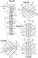
- the travel directions of the infrared rays IR shown by the arrows in Figs. 4A to 4E do not greatly change when passing through the interface of the front base 31 and the rear base 41.
- the infrared ray IR enters the front base 31 from the front substantially perpendicularly to pass through the inclined wall surfaces 37 and 47.
- the infrared ray IR enters the front base 31 from the front substantially perpendicularly to pass through the general wall surfaces 35 and 45. In either case, the infrared ray IR is emitted substantially perpendicularly from the rear surface 42 toward the rear after passing through the rear base 41.
- the infrared ray IR enters the front base 31 from the diagonally front lower side to pass through the inclined wall surfaces 37 and 47.
- the infrared ray IR enters the front base 31 from the diagonally front lower side to pass through the general wall surfaces 35 and 45. In either case, the infrared ray IR is emitted from the rear surface 42 toward the diagonally rear upper side after passing through the rear base 41.
- the front base 31 and the rear base 41 are made of the same type of plastic material.
- an angle a when the infrared ray IR enters the front base 31 from the atmosphere is the same as an angle b when the infrared ray IR is emitted from the rear base 41 to the atmosphere.
- the infrared ray IR is also refracted on the interface between the front base 31 and the decorative layer 52 (general wall surface 35, inclined wall surface 37, and bottom wall surface 38) and the interface between the decorative layer 52 and the rear base 41 (general wall surface 45, inclined wall surface 47, and top wall surface 48).
- the thickness of the decorative layer 52 is from several nanometers to several tens of nanometers, which is relatively small, both in the thin part of the decorative layer 52 configured only by the bright decorative layer 53 ( Figs. 4B and 4D ) and in the thick part of the decorative layer 52 configured by the bright decorative layer 53 and the colored decorative layer 54 ( Figs. 4C and 4E ).
- the thickness of the decorative layer 52 is significantly smaller than the thickness of the front base 31 and the thickness of the rear base 41, both of which are several millimeters. Thus, the refraction of the infrared ray IR on the decorative layer 52 is so small that the influence on the refraction of the infrared ray IR on the interface between the front base 31 and the rear base 41 can be ignored.
- the onboard sensor cover 24 is prevented from incorrectly recognizing the object due to a large refraction of the infrared ray IR on the interface.
- the front base 31 and the rear base 41 may be made of the same type of plastic material among multiple types of transparent plastic materials including PC, PMMA, and transparent ABS, which have been described above.
- the front base 31 and the rear base 41 have the same refractive index.
- the front base 31 and the rear base 41 may be made of different types of plastic materials.
- plastic materials in which the difference in the refractive index between the front base 31 and the rear base 41 is less than or equal to 7% are selected.
- Two of the multiple types of transparent plastic materials including PC, PMMA, and transparent ABS are selected.
- the refractive index of the front base 31 is approximate to the refractive index of the rear base 41.
- the bright decorative layer 53 may be provided on the general wall surface 35, and the colored decorative layer 54 may be provided on the inclined wall surface 37 and the bottom wall surface 38 in the recess 36.
- the decorative layer 52 may include only the bright decorative layer 53.
- the decorative layer 52 may include only the colored decorative layer 54.
- the colored decorative layer 54 may be formed by performing painting on the general wall surface 35 of the front base 31.
- the thickness T of the cover body 25 be set to a value that satisfies Equation 1 to reduce the attenuation amount of millimeter waves.
- the thickness T may be set to a value that does not satisfy Equation 1.
- the onboard sensor cover 24 is applicable to a vehicle 10 including, among the infrared sensor 22, the millimeter wave radar device 21, and the camera 23, only the infrared sensor 22 and the millimeter wave radar device 21 as an onboard sensor that detects surrounding situations of the vehicle 10.
- the onboard sensor cover 24 is also applicable to a vehicle 10 including the millimeter wave radar device 21, the infrared sensor 22, and the camera 23 such that they are arranged differently from the onboard sensor cover of the above-described embodiment.
- the millimeter wave radar device 21, the infrared sensor 22, and the camera 23 may be laid out in the left-right direction.
- the millimeter wave radar device 21, the infrared sensor 22, and the camera 23 may be arranged such that the positions thereof in the vertical direction are changed.
- the onboard sensor cover 24 is also applicable to a vehicle 10 in which an onboard sensor is arranged at a position in the radiator grille 11 that differs from the position of the radiator grille 11 of the above-described embodiment (i.e., at the upper part).
- the onboard sensor cover 24 is also applicable to a vehicle 10 in which an onboard sensor is arranged at a position that is located at the front end of the vehicle 10 and differs from the position of the radiator grille 11 (for example, located below the headlight 12 or incorporated in the bumper-integrated fender 13).
- the onboard sensor cover 24 is applicable to a vehicle 10 in which an onboard sensor is arranged at an outer end other than the front end, for example, the rear end or the side end.
Landscapes
- Engineering & Computer Science (AREA)
- Radar, Positioning & Navigation (AREA)
- Remote Sensing (AREA)
- Physics & Mathematics (AREA)
- Computer Networks & Wireless Communication (AREA)
- General Physics & Mathematics (AREA)
- Electromagnetism (AREA)
- Mechanical Engineering (AREA)
- Computer Security & Cryptography (AREA)
- Radar Systems Or Details Thereof (AREA)
- Optical Radar Systems And Details Thereof (AREA)
Abstract
An onboard sensor cover includes a cover body that includes front and rear bases and a decorative layer. The front base is made of a transparent plastic material that permits passage of an infrared ray and a millimeter wave and includes a rear surface in the transmission directions of the infrared ray and the millimeter wave that is configured by a first uneven surface. The rear base is made of a plastic material that permits passage of the infrared ray and the millimeter wave and includes a front surface in the transmission directions that is configured by a second uneven surface. The decorative layer is made of a material that reflects visible light and permits passage of the infrared ray and the millimeter wave and is in contact with the first and second uneven surfaces. The front base and the rear base are made of a plastic material in which a difference in a refractive index between the front base and the rear base is less than or equal to 7%.
Description
- The following description relates to an onboard sensor cover applied to a vehicle including an infrared sensor and a millimeter wave radar device as an onboard sensor that detects surrounding situations. The onboard sensor cover is configured to be arranged in front of the infrared sensor in a direction in which infrared rays are transmitted and in front of the millimeter wave radar device in a direction in which millimeter waves are transmitted.
- Infrared sensors and millimeter wave radar devices tend to be installed in a vehicle in order to detect surrounding situations. An infrared sensor transmits infrared rays toward the outside of the vehicle and receives the infrared rays that have struck and have been reflected by an object outside the vehicle including, for example, a leading vehicle and pedestrians. A millimeter wave radar device transmits millimeter waves toward the outside of the vehicle and receives the millimeter waves that have struck and have been reflected by the object outside the vehicle. The infrared rays and millimeter waves are used to recognize the object and detect the distance between the vehicle and the object and the relative speed. When exposed to the outside, the infrared sensor and the millimeter wave radar device are visible from the outer side of the vehicle, thereby adversely affecting the aesthetic appeal. Thus, when the infrared sensor is installed in the vehicle, a sensor cover is arranged in front of the infrared sensor in the transmission direction of the infrared rays to hide the infrared sensor and permit passage of the infrared rays. Further, when the millimeter wave radar device is installed in the vehicle, a sensor cover is arranged in front of the millimeter wave radar device in the transmission direction of the millimeter waves to hide the millimeter wave radar device and permit passage of the millimeter waves.
- Recently, there has been a need for installing both the infrared sensor and the millimeter wave radar device in the vehicle. Thus, it is desired that a common onboard sensor cover permit passage of infrared rays and millimeter waves and hide the infrared sensor and the millimeter wave radar device.
- However, there have been no onboard sensor covers that permit passage of infrared rays and millimeter waves mainly because an onboard sensor cover for an infrared sensor has the following problems.
-
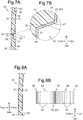
Fig. 8A shows a typicalonboard sensor cover 80 for an infrared sensor. Theonboard sensor cover 80 includes abase 81 and adecorative layer 91, which is provided on the rear surface of thebase 81 in the transmission direction of infrared rays. Thebase 81 is made of a transparent plastic material that permits passage of infrared rays. Thedecorative layer 91 is made of a material that reflects visible light and permits passage of infrared rays. - Thus, the
decorative layer 91 is visible through thetransparent base 81 from the front of theonboard sensor cover 80 in the transmission direction, and theonboard sensor cover 80 is decorated by thedecorative layer 91. Further, thedecorative layer 91, which is located frontward from the infrared sensor in the transmission direction, prevents the infrared sensor from being viewed. This improves the aesthetic appeal of theonboard sensor cover 80 and its surroundings. - To further improve the aesthetic appeal of the
onboard sensor cover 80, it is desired that thedecorative layer 91 look three-dimensional. For example, as shown inFigs. 7A and 7B , afront surface 82 of thebase 81 in the transmission direction may be configured by a flat surface, and the rear surface of thebase 81 in the transmission direction may be configured by anuneven surface 83. - More specifically, a
general portion 84 andrecesses 86 are provided on the rear part of thebase 81 in the transmission direction. Thegeneral portion 84 includes a flatgeneral wall surface 85, which is substantially orthogonal to the transmission direction. Eachrecess 86 is recessed frontward from thegeneral portion 84 in the transmission direction and includes a pair of opposinginclined wall surfaces 87 and abottom wall surface 88. Theinclined wall surfaces 87 are inclined with respect to the transmission direction such that the distance between theinclined wall surfaces 87 decreases toward the front side in the transmission direction. Thebottom wall surface 88 includes a flat surface that is substantially orthogonal to the transmission direction. Thegeneral wall surface 85, theinclined wall surfaces 87, thebottom wall surface 88, and the like configure theuneven surface 83. - However, the refractive index of the
base 81 greatly differs from the refractive index of the atmosphere. Thus, when an infrared ray IR passes through the interface between theinclined wall surface 87 of therecess 86 and the atmosphere, the infrared ray IR greatly refracts to change its travel direction. The angle when the infrared ray IR enters thebase 81 from thefront surface 82 greatly differs from the angle when the infrared ray IR is emitted from theinclined wall surface 87 of thebase 81. Due to this difference, it is difficult for the infrared sensor to correctly recognize the object. - The infrared ray IR is also refracted on the interface between the
decorative layer 91 and thebase 81 and the interface between thedecorative layer 91 and the atmosphere. However, the thickness of thedecorative layer 91 is significantly smaller than the thickness of thebase 81. Thus, the refraction of the infrared ray IR on thedecorative layer 91 has a negligible influence on the refraction of the infrared ray IR on the interface between thebase 81 and the atmosphere. - From such a circumstance, the
onboard sensor cover 80, which configures the rear surface of thebase 81 in the transmission direction by theuneven surface 83 and provides thedecorative layer 91 on theuneven surface 83, is useless. - Thus, typically, as shown in
Figs. 8A and 8B , the rear surface of thebase 81 in the transmission direction is configured by a singleflat surface 89, which is substantially orthogonal to the transmission direction. Thedecorative layer 91 is provided on the flat surface 89 (refer to, for example, Japanese Laid-Open Patent Publication No.2004-198617 3646930 patterned portion 92 of thedecorative layer 91 is provided such that thedecorative layer 91 looks three-dimensional. For example, as shown inFig. 8B , when the patternedportion 92 includesstraight lines 93, which are arranged in parallel to one another, portions where the distance between adjacent ones of thestraight lines 93 is long and portions where the distance between adjacent ones of thestraight lines 93 is short are set such that thepatterned portion 92 has rough and fine parts. In this case, the long-distance portions (rough portions 94) look as if they are located on the front side (upstream side) in the transmission direction, and the short-distance portions (fine portions 95) look as if they are located on the rear side (downstream side) in the transmission direction. - However, in the typical
onboard sensor cover 80 shown inFigs. 8A and 8B , whereas thepatterned portion 92 of thedecorative layer 91 looks three-dimensional when theonboard sensor cover 80 is viewed in a particular direction such as from the front side in the transmission direction (direction orthogonal to the front surface 82), thepatterned portion 92 of thedecorative layer 91 does not look three-dimensional when theonboard sensor cover 80 is viewed from the diagonally front side. Thus, there have been no onboard sensor covers that overcome this problem and permit passage of both infrared rays and millimeter waves. - It is an objective of the present disclosure to provide an onboard sensor cover that permits passage of millimeter waves without obstructing object recognition by an infrared sensor and makes a decorative layer look three-dimensional regardless of an angle from which the decorative layer is viewed.
- This Summary is provided to introduce a selection of concepts in a simplified form that are further described below in the Detailed Description. This Summary is not intended to identify key features or essential features of the claimed subject matter, nor is it intended to be used as an aid in determining the scope of the claimed subject matter.
- To solve the above-described problem, an onboard sensor cover applied to a vehicle according to one aspect of the present disclosure is provided. The vehicle includes, as an onboard sensor that detects a surrounding situation, an infrared sensor that transmits an infrared ray toward an outside of the vehicle and receives the infrared ray that has struck and has been reflected by an object outside the vehicle and a millimeter wave radar device that transmits a millimeter wave toward the outside of the vehicle and receives the millimeter wave that has struck and has been reflected by the object outside the vehicle. The onboard sensor cover includes a cover body configured to be arranged in front of the infrared sensor in a transmission direction of the infrared ray and in front of the millimeter wave radar device in a transmission direction of the millimeter wave. The cover body includes a front base made of a transparent plastic material that permits passage of the infrared ray and the millimeter wave, the front base including a rear surface in the transmission directions of the infrared ray and the millimeter wave, the rear surface being configured by a first uneven surface, a rear base made of a plastic material that permits passage of the infrared ray and the millimeter wave and arranged on a rear side of the front base in the transmission directions, the rear base including a front surface in the transmission directions, the front surface being configured by a second uneven surface that corresponds to the first uneven surface of the front base, and a decorative layer made of a material that reflects visible light and permits passage of the infrared ray and the millimeter wave, the decorative layer being in contact with the first uneven surface of the front base and the second uneven surface of the rear base between the front base and the rear base. The front base and the rear base are made of a plastic material in which a difference in a refractive index between the front base and the rear base is less than or equal to 7%.
- The above-described term "transparent" includes not only a colorless and transparent state, but also a colored and transparent state.
- Other features and aspects will be apparent from the following detailed description, the drawings, and the claims.
-
-
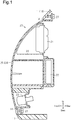
Fig. 1 is a partial side cross-sectional view of an onboard sensor cover according to an embodiment, showing the onboard sensor cover attached to the front end of a vehicle and the surrounding portion of the onboard sensor cover. -
Fig. 2A is a front view of the vehicle to which the onboard sensor cover of the embodiment is attached. -
Fig. 2B is an enlarged partial front view showing a part ofFig. 2A . -
Fig. 3A is a partial side cross-sectional view showing the cover body inFig. 1 . -
Fig. 3B is an enlarged partial side cross-sectional view showing a part ofFig. 3A . -
Fig. 4A is a partial side cross-sectional view showing the cover body of the embodiment and a path through which infrared rays pass. -
Figs. 4B to 4E are enlarged partial cross-sectional side views each showing a part ofFig. 4A . -
Fig. 5 is a graph illustrating the result of measuring the relationship between the attenuation amount of a millimeter wave and the distance (measurement distance) from the millimeter wave radar device to the cover body of the onboard sensor cover. -
Fig. 6 is a graph illustrating the result of measuring the relationship between the transmittance and wavelength of an infrared ray in the cover body of the onboard sensor cover. -
Fig. 7A is a partial side cross-sectional view of a typical onboard sensor cover, showing a hypothetical onboard sensor cover in which the rear surface of a base is configured by an uneven surface and a decorative layer is provided on the uneven surface. -
Fig. 7B is an enlarged side partial cross-sectional view illustrating a part ofFig. 7A . -
Fig. 8A is a partial side cross-sectional view of a typical onboard sensor cover in which the rear surface of a base is configured by a flat surface and a decorative layer is provided on the flat surface. -
Fig. 8B is a partial front view illustrating the patterned portion of the decorative layer inFig. 8A . - Throughout the drawings and the detailed description, the same reference numerals refer to the same elements. The drawings may not be to scale, and the relative size, proportions, and depiction of elements in the drawings may be exaggerated for clarity, illustration, and convenience.
- This description provides a comprehensive understanding of the methods, apparatuses, and/or systems described. Modifications and equivalents of the methods, apparatuses, and/or systems described are apparent to one of ordinary skill in the art. Sequences of operations are exemplary, and may be changed as apparent to one of ordinary skill in the art, with the exception of operations necessarily occurring in a certain order. Descriptions of functions and constructions that are well known to one of ordinary skill in the art may be omitted.
- Exemplary embodiments may have different forms, and are not limited to the examples described. However, the examples described are thorough and complete, and convey the full scope of the disclosure to one of ordinary skill in the art.
- An
onboard sensor cover 24 according to an embodiment will now be described with reference toFigs. 1 to 6 . - In the following description, the direction in which a
vehicle 10 travels forward will be referred to as the front, and the reverse direction will be referred to as the rear. The vertical direction refers to the vertical direction of thevehicle 10, and the left-right direction refers to the width direction of thevehicle 10 that matches with the left-right direction when thevehicle 10 is moving forward. InFigs. 3A to Fig. 4E , the dimensions of components of theonboard sensor cover 24 are changed such that the components are recognizable. The same applies toFigs. 7A to Fig. 8B , which illustrate the related art. To facilitate understanding,Fig. 1 shows that acover body 25 of theonboard sensor cover 24 is configured by a single member. However, as shown inFig. 3A , thecover body 25 is configured by multiple members. The details will be described below. - As shown in
Fig. 2A , thevehicle 10 includes aradiator grille 11, a pair ofheadlights 12, and a pair of bumper-integratedfenders 13 as vehicle exterior parts, which are attached to the front end of the vehicle body of thevehicle 10. Theheadlights 12 and the bumper-integratedfenders 13 are arranged on the left and right sides of theradiator grille 11. Theradiator grille 11 guides outside air such as relative wind to a radiator (not shown) to cool the radiator. - As shown in
Fig. 1 , aquadrilateral window 14 opens in the upper part of theradiator grille 11, and avehicle sensor unit 20 is arranged between thewindow 14 and the radiator. - As shown in
Figs. 1 and2B , thevehicle sensor unit 20 includes a millimeterwave radar device 21, aninfrared sensor 22, acamera 23, and theonboard sensor cover 24. The millimeterwave radar device 21, theinfrared sensor 22, and thecamera 23 are onboard sensors that detect surrounding situations of thevehicle 10 and are laid out in the vertical direction. Theonboard sensor cover 24 covers the millimeterwave radar device 21, theinfrared sensor 22, and thecamera 23 from the front of thevehicle 10. - The millimeter
wave radar device 21 transmits millimeter waves toward the outside of the vehicle, more specifically, toward a predetermined angular range in front of thevehicle 10 and receives millimeter waves that have struck and have been reflected by an object outside the vehicle including a leading vehicle, pedestrians, and the like. Millimeter waves are radio waves with wavelengths of 1 mm to 10 mm and frequencies of 30 GHz to 300 GHz. The millimeterwave radar device 21 recognizes the object outside the vehicle from the time difference between transmitted millimeter waves and received millimeter waves, the strength of received waves, and the like and detects the distance between thevehicle 10 and the object and the relative speed. The millimeterwave radar device 21 is characterized by being resistant to bad weather such as rain, fog, and snow, and having a longer detectable distance than other modes. - The
infrared sensor 22 is located below and adjacent to the millimeterwave radar device 21. Theinfrared sensor 22 transmits infrared rays toward the front of thevehicle 10 over a broader angular range than the millimeterwave radar device 21 and receives the infrared rays that have struck and have been reflected by the object outside the vehicle such as a leading vehicle, pedestrians, and the like. Infrared ray is a kind of electromagnetic wave and has a longer wavelength than the wavelength of visible light (0.36 µm to 0.83 µm). Theinfrared sensor 22 detects objects closer to thevehicle 10 than objects to be detected by the millimeterwave radar device 21. Based on the transmitted infrared rays and the received infrared rays, theinfrared sensor 22 recognizes the object outside the vehicle and detects the distance between thevehicle 10 and the object and the relative speed. - The
camera 23 is located below and adjacent to theinfrared sensor 22. Thecamera 23 is located at a position deviated both from a detection region of the millimeterwave radar device 21 and a detection region of theinfrared sensor 22. The detection region of the millimeterwave radar device 21 refers to a region for passage of millimeter waves transmitted from the millimeterwave radar device 21 and millimeter waves that have struck and have been reflected by the object. The detection region of theinfrared sensor 22 refers to a region for passage of infrared rays transmitted from theinfrared sensor 22 and infrared rays that have struck and have been reflected by the object. - As described above, the millimeter
wave radar device 21 transmits millimeter waves toward the front of thevehicle 10, and theinfrared sensor 22 transmits infrared rays toward the front of thevehicle 10. Thus, the millimeterwave radar device 21 transmits millimeter waves and theinfrared sensor 22 transmits infrared rays in a direction from the rear to the front of thevehicle 10. The front in the transmission direction of millimeter waves and infrared rays matches the front of thevehicle 10, and the rear in the transmission direction matches the rear of thevehicle 10. Thus, in the following description, the front in the transmission direction of millimeter waves and infrared rays is simply referred to as "frontward" or "front," and the rear in the transmission direction is simply referred to as "rearward" or "rear." - The
onboard sensor cover 24 includes thecover body 25 and anattachment portion 26. Thecover body 25 has a shape corresponding to thewindow 14 of the radiator grille 11 (rectangular shape) and is arranged on thewindow 14. Theattachment portion 26 is provided on the rear side of thecover body 25. The millimeterwave radar device 21, theinfrared sensor 22, and thecamera 23 are attached to theattachment portion 26 to configure thevehicle sensor unit 20 as a single unit. - The
cover body 25 includesmount portions 27 at least on its upper end and lower end. At themount portions 27, thecover body 25 is attached to theradiator grille 11 or a peripheral portion of thewindow 14 in the vehicle body through, for example, engagement of clips, screws, or tabs. - As shown in
Figs. 3A and 3B , most of thecover body 25 except themount portions 27 includes afront base 31, adecorative layer 52, and arear base 41. - The
front base 31 is made of a transparent plastic material that permits passage of millimeter waves and infrared rays. The term "transparent" in this specification includes not only a colorless and transparent state, but also a colored and transparent state. Thefront base 31 includes afront surface 32, which is configured by a single flat surface that is substantially orthogonal to the front-rear direction. Thefront surface 32 includes a design surface of theonboard sensor cover 24. The rear surface of thefront base 31 is configured by a firstuneven surface 33. - More specifically, the rear part of the
front base 31 is provided with ageneral portion 34, which includes a flatgeneral wall surface 35 that is substantially orthogonal to the front-rear direction, and recesses 36, which are recessed frontward from thegeneral portion 34. Therecesses 36 each include a pair of inclined wall surfaces 37, which are opposed to each other in the vertical direction, and abottom wall surface 38. The inclined wall surfaces 37 are inclined with respect to the front-rear direction such that the distance between the inclined wall surfaces 37 decreases toward the front side. Thebottom wall surface 38 is configured by a flat surface that is substantially orthogonal to the front-rear direction. Thegeneral wall surface 35, the inclined wall surfaces 37, and thebottom wall surface 38 configure part of the firstuneven surface 33. - The
rear base 41 is made of a plastic material that permits passage of millimeter waves and infrared rays and is arranged on the rear side of thefront base 31. Therear base 41 includes arear surface 42, which is configured by a single flat surface that is substantially orthogonal to the front-rear direction. Therear base 41 includes a front surface configured by a seconduneven surface 43, which corresponds to the firstuneven surface 33 of thefront base 31. - More specifically, the portion serving as the front part of the
rear base 41 and the rear part of thegeneral portion 34 of thefront base 31 is provided with ageneral portion 44, which includes a flatgeneral wall surface 45, which is substantially orthogonal to the front-rear direction. The portion serving as the front part of therear base 41 and the rear part of eachrecess 36 of thefront base 31 is provided with aprotrusion 46, which protrudes frontward from thegeneral portion 44 and into therecess 36. Theprotrusion 46 includes a pair of inclined wall surfaces 47 and atop wall surface 48. The inclined wall surfaces 47 are inclined with respect to the front-rear direction such that the distance between the inclined wall surfaces 47 decreases toward the front side. Thetop wall surface 48 is configured by a flat surface that is substantially orthogonal to the front-rear direction. Thegeneral wall surface 45, the inclined wall surfaces 47, and thetop wall surface 48 configure part of the seconduneven surface 43. - The
front base 31 and therear base 41 are made of plastic materials in which the difference in refractive index between thefront base 31 and therear base 41 is less than or equal to 7%. The plastic material mainly includes polycarbonate plastic (PC), poly methyl methacrylate plastic (PMMA), and transparent acrylonitrile-butadienestyrene copolymer plastic (ABS). The refractive index of PC is 1.59, the refractive index of PMMA is 1.49, and the refractive index of transparent ABS is 1.57. - Other transparent plastics such as methyl methacrylate-styrene copolymer plastic (MBS), polyamide plastic (PA), and polystyrene plastic (PS) may also be used. The refractive index of MBS is 1.50, the refractive index of PA is 1.51, and the refractive index of transparent PS is 1.60.
- The
front base 31 and therear base 41 are made of any one of multiple types of plastic materials including PC, PMMA, and transparent ABS. Thefront base 31 and therear base 41 may be made of the same type of plastic material or may be made of different types of plastic materials. In the present embodiment, thefront base 31 and therear base 41 are both made of PC. Thus, thefront base 31 and therear base 41 have the same refractive index. PC has a relative permittivity of 2.9 to 3.0. The relative permittivity refers to the ratio of the permittivity of the front base 31 (rear base 41) to the permittivity of a vacuum. The permittivity refers to a physical property indicating the degrees of characteristics that cause dielectric polarization to occur in the electric charges of matter. - The
decorative layer 52 decorates theonboard sensor cover 24 and has a thickness of several micrometers to several tens of micrometers. Thedecorative layer 52 is made of a material that reflects visible light and permits passage of infrared rays and millimeter waves. Thedecorative layer 52 is in close contact with the firstuneven surface 33 and the seconduneven surface 43 between thefront base 31 and therear base 41. Thedecorative layer 52 includes a brightdecorative layer 53 and a coloreddecorative layer 54. The ornamental portion represented by thedecorative layer 52 includes, for example, a background part and a patterned part such as characters and marks. The background part is configured by, for example, the coloreddecorative layer 54. The patterned part is configured by, for example, the brightdecorative layer 53. - The colored
decorative layer 54 includes an infrared ray passage ink (IR ink) layer made of an infrared ray passage ink and is, for example, black, blue, or red. IR ink is known as a material having a high light transmittance of infrared rays and a low light transmittance of visible light. The coloreddecorative layer 54 may have a single color or may be patterned by multiple colors. The coloreddecorative layer 54 is formed by, for example, performing printing such as screen printing on thegeneral wall surface 35 of thefront base 31. - The bright
decorative layer 53 is formed by performing sputtering, vapor deposition, or coating on theinclined wall surface 37 and thebottom wall surface 38 of thefront base 31 and on the entire rear surface of the coloreddecorative layer 54. Thus, thedecorative layer 52 has a double-layer structure including the coloreddecorative layer 54 and the brightdecorative layer 53 on thegeneral wall surface 35 of thefront base 31. In the present embodiment, the brightdecorative layer 53 includes a dielectric multilayer film (i.e., cold mirror layer). The dielectric multilayer film is a film formed by alternately laminating a first dielectric thin film made of a high refractive-index material and a second dielectric thin film made of a low refractive-index material, which has a lower refractive index than the high refractive-index material. The high refractive-index material includes, for example, titanium dioxide (TiO2), aluminum oxide (AL2O3), and zirconium oxide (ZrO2). The low refractive-index material includes, for example, silicon dioxide (SiO2), zinc peroxide (ZnO2), and magnesium fluoride (MgF2). - For example, a dielectric multilayer film formed by alternately overlapping five first dielectric thin films made of titanium dioxide (TiO2) and five second dielectric thin films made of silicon dioxide (SiO2) with each other can be used as the bright
decorative layer 53. - The
decorative layer 52 is not provided on a portion of thecover body 25 that serves as the front side in an image-capturing direction of thecamera 23. This portion of thecover body 25 permits passage of visible light. Thus, thecamera 23 can be used to capture the images of the surroundings of thevehicle 10 through outside light that passes through this portion of thecover body 25. - It is desired that the
camera 23 have the same color as the coloreddecorative layer 54, which configures the background part of the ornamental portion by thedecorative layer 52. In this case, while thecamera 23 is visually recognizable from the front of thevehicle 10 through thecover body 25, thecamera 23 is unnoticed. - The
cover body 25 is required to have a small amount of attenuation that occurs when millimeter waves pass through thecover body 25. It has been found that the attenuation amount of millimeter waves has a certain relationship with the thickness of thecover body 25. That is, it has been found that when thicknesses are set to satisfy a certain condition (refer to the following Equation 1), the attenuation amount is smaller in the thicknesses than in other thicknesses. - Thus, in the present embodiment, when the thickness of the portion of the
cover body 25 excluding themount portion 27 is set as T, the wavelength of a millimeter wave is set as λe, the relative permittivity of the bases (the average value of the relative permittivity of the front base and the rear base) is set as εp, and an integer is set as n, the thickness T is set to a value that satisfies the followingEquation 1.
- In this manner, the thickness T of the
cover body 25 is set to a value that is an integral multiple of a value obtained by dividing a half-wavelength by the square root of the average value of the relative permittivity. When thefront base 31 and therear base 41 are made of PC, the thickness T is set to, for example, 2.4 mm or 3.6 mm. In this setting, the attenuation amount of millimeter waves passing through thecover body 25 is limited to less than or equal to 2.0 dB, which is an allowable value. -
Fig. 5 illustrates the result of measuring the relationship between the distance (measurement distance) from the millimeterwave radar device 21 to thecover body 25 and the attenuation amount of a millimeter wave passing through thecover body 25.Fig. 5 reveals that the attenuation amount of the millimeter wave increases and decreases in accordance with the distance (measurement distance). The increase and decrease are caused by the interference between millimeter waves that have struck and have been reflected by theonboard sensor cover 24 with millimeter waves transmitted from the millimeterwave radar device 21 and by reinforcement and attenuation of the millimeter waves in accordance with the distance.Fig. 5 also reveals that the attenuation amount is limited to 2.0 dB or lower even at the maximum. - The transmittance of infrared rays in the
cover body 25 is greater than or equal to 70%, which is an allowable value. Thus, theonboard sensor cover 24, which is arranged on an optical path of infrared rays, is unlikely to obstruct a normal operation of theinfrared sensor 22. -
Fig. 6 illustrates the result of measuring the relationship between the transmittance and wavelength of the infrared ray IR in thecover body 25, in which the brightdecorative layer 53 is configured by a dielectric multilayer film (cold mirror layer).Fig. 6 reveals that the transmittance of the infrared ray IR is greater than or equal to 70% in a wavelength region of 850 nm or longer. - Further, the
vehicle 10 is equipped with an electronic control unit (not shown). The millimeterwave radar device 21, theinfrared sensor 22, and thecamera 23 are connected to the electronic control unit. The electronic control unit executes various types of processes to support the driving of thevehicle 10 according to the surrounding situations of thevehicle 10, which are obtained from output signals of the millimeterwave radar device 21, theinfrared sensor 22, and thecamera 23. The processes include a process of warning that thevehicle 10 may deviate from the lane, a process of warning that thevehicle 10 may collide, and a process of automatically adjusting the distance between vehicles. - The operation and advantages of the
onboard sensor cover 24 of the above-described embodiment will now be described. - When visible light enters the
cover body 25 of the onboard sensor cover 24 from the front of thevehicle 10, the visible light passes through thefront base 31 and reflects on the coloreddecorative layer 54 and the brightdecorative layer 53 in thedecorative layer 52. The reflection of the visible light on the brightdecorative layer 53, which is configured by a cold mirror layer, shines like metal. Further, the reflection of the visible light on the coloreddecorative layer 54, which is configured by an infrared ray passage ink, results in colored ornamentation. - When the
onboard sensor cover 24 is viewed from the front of thevehicle 10, thedecorative layer 52 looks as if it is located on the rear side (downstream side) of thefront base 31 through thefront base 31. The color of the coloreddecorative layer 54 is visible in the coloreddecorative layer 54 of thedecorative layer 52. The brightdecorative layer 53 of thedecorative layer 52 looks shiny like metal. In this manner, thedecorative layer 52 ornaments theonboard sensor cover 24, thereby increasing the aesthetic appeal of theonboard sensor cover 24 and its peripheral portions. - The rear surface of the
front base 31 is configured by the firstuneven surface 33. Thedecorative layer 52 is provided on the firstuneven surface 33 and is uneven. Thus, when theonboard sensor cover 24 is viewed from the front of thevehicle 10, the recessed part of the decorative layer 52 (i.e., the brightdecorative layer 53 on theinclined wall surface 37 and the bottom wall surface 38) looks as if it is located frontward from (located upstream of) the coloreddecorative layer 54 on thegeneral wall surface 35. In other words, the entiredecorative layer 52 looks as if it is three-dimensional in the front-rear direction. This further increases the aesthetic appeal of theonboard sensor cover 24 and its peripheral portions. Such an effect is not easily obtained from the typicalonboard sensor cover 80, in which the rear surface of thebase 81 is configured by the singleflat surface 89 and thedecorative layer 91 is provided on theflat surface 89, as shown inFigs. 8A and 8B . - The reflection of visible light on the
decorative layer 52 occurs in front of theinfrared sensor 22 and in front of the millimeterwave radar device 21. Thedecorative layer 52 hides theinfrared sensor 22 and the millimeterwave radar device 21. Thus, theinfrared sensor 22 and the millimeterwave radar device 21 are difficult to see from the front of theonboard sensor cover 24. - Thus, as compared to an onboard sensor cover in which the
infrared sensor 22 and the millimeterwave radar device 21 are incorporated into the vehicle body in an exposed state or an onboard sensor cover in which theinfrared sensor 22 and the millimeterwave radar device 21 look transparent through thecover body 25 of theonboard sensor cover 24, the aesthetic appeal of theonboard sensor cover 24 and its peripheral portions is improved. - When infrared rays are transmitted from the
infrared sensor 22 toward the outside of the vehicle, the infrared rays pass through therear base 41, thedecorative layer 52, and thefront base 31 of thecover body 25 in this order. The infrared rays that have struck and have been reflected by an object outside the vehicle including a leading vehicle and pedestrians pass through thefront base 31, thedecorative layer 52, and therear base 41 in this order and are then received by theinfrared sensor 22. Based on the transmitted and received infrared rays, theinfrared sensor 22 recognizes the object outside the vehicle and detects the distance between thevehicle 10 and the object and the relative speed. - When millimeter waves are transmitted from the millimeter
wave radar device 21 toward the outside of the vehicle, the millimeter waves pass through therear base 41, thedecorative layer 52, and thefront base 31 of thecover body 25 in this order. The millimeter waves that have struck and have been reflected by the object outside the vehicle including a leading vehicle and pedestrians pass through thefront base 31, thedecorative layer 52, and therear base 41 in this order and are then received by the millimeterwave radar device 21. Based on the transmitted and received millimeter waves, the millimeterwave radar device 21 recognizes the object outside the vehicle and detects the distance between thevehicle 10 and the object and the relative speed. - The thickness T of the
cover body 25 of theonboard sensor cover 24 is set to a value that satisfies the above-describedEquation 1. Thus, as compared to when the thickness T is set to a value that does not satisfyEquation 1, the attenuation amount of millimeter waves passing through thecover body 25 decreases. This allows the millimeterwave radar device 21 to recognize the object outside the vehicle and detect the distance between thevehicle 10 and the object and the relative speed as described above. - The image of an external situation of the
vehicle 10 is captured by thecamera 23 through a part of thecover body 25 where thedecorative layer 52 is not provided. - In the present embodiment, since the
front base 31 and therear base 41 are made of the same type of plastic material (PC), thefront base 31 and therear base 41 have the same refractive index. Thus, the travel directions of the infrared rays IR shown by the arrows inFigs. 4A to 4E do not greatly change when passing through the interface of thefront base 31 and therear base 41. - In
Fig. 4D , the infrared ray IR enters thefront base 31 from the front substantially perpendicularly to pass through the inclined wall surfaces 37 and 47. InFig. 4E , the infrared ray IR enters thefront base 31 from the front substantially perpendicularly to pass through the general wall surfaces 35 and 45. In either case, the infrared ray IR is emitted substantially perpendicularly from therear surface 42 toward the rear after passing through therear base 41. - In
Fig. 4B , the infrared ray IR enters thefront base 31 from the diagonally front lower side to pass through the inclined wall surfaces 37 and 47. InFig. 4C , the infrared ray IR enters thefront base 31 from the diagonally front lower side to pass through the general wall surfaces 35 and 45. In either case, the infrared ray IR is emitted from therear surface 42 toward the diagonally rear upper side after passing through therear base 41. - The
front base 31 and therear base 41 are made of the same type of plastic material. Thus, inFigs. 4A to 4E , an angle a when the infrared ray IR enters thefront base 31 from the atmosphere is the same as an angle b when the infrared ray IR is emitted from therear base 41 to the atmosphere. - The infrared ray IR is also refracted on the interface between the
front base 31 and the decorative layer 52 (general wall surface 35, inclinedwall surface 37, and bottom wall surface 38) and the interface between thedecorative layer 52 and the rear base 41 (general wall surface 45, inclinedwall surface 47, and top wall surface 48). However, the thickness of thedecorative layer 52 is from several nanometers to several tens of nanometers, which is relatively small, both in the thin part of thedecorative layer 52 configured only by the bright decorative layer 53 (Figs. 4B and 4D ) and in the thick part of thedecorative layer 52 configured by the brightdecorative layer 53 and the colored decorative layer 54 (Figs. 4C and 4E ). The thickness of thedecorative layer 52 is significantly smaller than the thickness of thefront base 31 and the thickness of therear base 41, both of which are several millimeters. Thus, the refraction of the infrared ray IR on thedecorative layer 52 is so small that the influence on the refraction of the infrared ray IR on the interface between thefront base 31 and therear base 41 can be ignored. - Accordingly, the
onboard sensor cover 24 is prevented from incorrectly recognizing the object due to a large refraction of the infrared ray IR on the interface. This differs from the typicalonboard sensor cover 80, which includes the base 81 having the rear surface configured by theuneven surface 83, and thedecorative layer 91 in close contact with theuneven surface 83 as shown inFigs. 7A and 7B . - The above-described embodiment may be modified as follows.
- The
front base 31 and therear base 41 may be made of the same type of plastic material among multiple types of transparent plastic materials including PC, PMMA, and transparent ABS, which have been described above. In this case, thefront base 31 and therear base 41 have the same refractive index. Thus, the same operation and advantages as the above-described embodiment can be gained. - The
front base 31 and therear base 41 may be made of different types of plastic materials. In this case, plastic materials in which the difference in the refractive index between thefront base 31 and therear base 41 is less than or equal to 7% are selected. Two of the multiple types of transparent plastic materials including PC, PMMA, and transparent ABS are selected. - In this case, the refractive index of the
front base 31 is approximate to the refractive index of therear base 41. Thus, the same operation and advantages as the above-described embodiment can be gained. - In a manner opposite to the above-described embodiment, the bright
decorative layer 53 may be provided on thegeneral wall surface 35, and the coloreddecorative layer 54 may be provided on theinclined wall surface 37 and thebottom wall surface 38 in therecess 36. - The
decorative layer 52 may include only the brightdecorative layer 53. Alternatively, thedecorative layer 52 may include only the coloreddecorative layer 54. - The colored
decorative layer 54 may be formed by performing painting on thegeneral wall surface 35 of thefront base 31. - In the
onboard sensor cover 24, it is desired that the thickness T of thecover body 25 be set to a value that satisfiesEquation 1 to reduce the attenuation amount of millimeter waves. Instead, when the attenuation of a larger amount of millimeter waves than the above-described embodiment is allowable, the thickness T may be set to a value that does not satisfyEquation 1. - The
onboard sensor cover 24 is applicable to avehicle 10 including, among theinfrared sensor 22, the millimeterwave radar device 21, and thecamera 23, only theinfrared sensor 22 and the millimeterwave radar device 21 as an onboard sensor that detects surrounding situations of thevehicle 10. - The
onboard sensor cover 24 is also applicable to avehicle 10 including the millimeterwave radar device 21, theinfrared sensor 22, and thecamera 23 such that they are arranged differently from the onboard sensor cover of the above-described embodiment. For example, the millimeterwave radar device 21, theinfrared sensor 22, and thecamera 23 may be laid out in the left-right direction. Alternatively, the millimeterwave radar device 21, theinfrared sensor 22, and thecamera 23 may be arranged such that the positions thereof in the vertical direction are changed. - The
onboard sensor cover 24 is also applicable to avehicle 10 in which an onboard sensor is arranged at a position in theradiator grille 11 that differs from the position of theradiator grille 11 of the above-described embodiment (i.e., at the upper part). - The
onboard sensor cover 24 is also applicable to avehicle 10 in which an onboard sensor is arranged at a position that is located at the front end of thevehicle 10 and differs from the position of the radiator grille 11 (for example, located below theheadlight 12 or incorporated in the bumper-integrated fender 13). - The
onboard sensor cover 24 is applicable to avehicle 10 in which an onboard sensor is arranged at an outer end other than the front end, for example, the rear end or the side end. - Various changes in form and details may be made to the examples above without departing from the spirit and scope of the claims and their equivalents. The examples are for the sake of description only, and not for purposes of limitation. Descriptions of features in each example are to be considered as being applicable to similar features or aspects in other examples. Suitable results may be achieved if sequences are performed in a different order, and/or if components in a described system, architecture, device, or circuit are combined differently, and/or replaced or supplemented by other components or their equivalents. The scope of the disclosure is not defined by the detailed description, but by the claims and their equivalents. All variations within the scope of the claims and their equivalents are included in the disclosure.
- It is explicitly stated that all features disclosed in the description and/or the claims are intended to be disclosed separately and independently from each other for the purpose of original disclosure as well as for the purpose of restricting the claimed invention independent of the composition of the features in the embodiments and/or the claims. It is explicitly stated that all value ranges or indications of groups of entities disclose every possible intermediate value or intermediate entity for the purpose of original disclosure as well as for the purpose of restricting the claimed invention, in particular as limits of value ranges.
Claims (5)
- An onboard sensor cover applied to a vehicle (10), the vehicle (10) including, as an onboard sensor that detects a surrounding situation, an infrared sensor (22) that transmits an infrared ray toward an outside of the vehicle and receives the infrared ray that has struck and has been reflected by an object outside the vehicle and a millimeter wave radar device (21) that transmits a millimeter wave toward the outside of the vehicle and receives the millimeter wave that has struck and has been reflected by the object outside the vehicle, characterized in that
the onboard sensor cover comprises a cover body (25) configured to be arranged in front of the infrared sensor (22) in a transmission direction of the infrared ray and in front of the millimeter wave radar device (21) in a transmission direction of the millimeter wave,
the cover body (25) includesa front base (31) made of a transparent plastic material that permits passage of the infrared ray and the millimeter wave, the front base (31) including a rear surface in the transmission directions of the infrared ray and the millimeter wave, the rear surface being configured by a first uneven surface (33),a rear base (41) made of a plastic material that permits passage of the infrared ray and the millimeter wave and arranged on a rear side of the front base (31) in the transmission directions, the rear base (41) including a front surface in the transmission directions, the front surface being configured by a second uneven surface (43) that corresponds to the first uneven surface (33) of the front base (31), anda decorative layer (52) made of a material that reflects visible light and permits passage of the infrared ray and the millimeter wave, the decorative layer (52) being in contact with the first uneven surface (33) of the front base (31) and the second uneven surface (43) of the rear base (41) between the front base (31) and the rear base (41), andthe front base (31) and the rear base (41) are made of a plastic material in which a difference in a refractive index between the front base (31) and the rear base (41) is less than or equal to 7%. - The onboard sensor cover according to claim 1, characterized in that the front base (31) and the rear base (41) are made of the same type of plastic material.
- The onboard sensor cover according to claim 1, characterized in that the front base (31) and the rear base (41) are each made of any one of plastic materials of polycarbonate plastic (PC), poly methyl methacrylate plastic (PMMA), and acrylonitrile-butadiene-styrene copolymer plastic (ABS).
- The onboard sensor cover according to any one of claims 1 to 3, characterized in that the decorative layer (52) includes at least one of a cold mirror layer or an infrared ray passage ink layer.
- The onboard sensor cover according to any one of claims 1 to 4, characterized in that when a thickness of the cover body (25) is set as T, a wavelength of the millimeter wave is set as λe, an average value of a relative permittivity of the front base (31) and the rear base (41) is set as εp, and an integer is set as n, the thickness T is set to a value that satisfies an equation, T = {(λe / 2) / √(εp)}n.
Applications Claiming Priority (1)
| Application Number | Priority Date | Filing Date | Title |
|---|---|---|---|
| JP2018198286A JP2020067291A (en) | 2018-10-22 | 2018-10-22 | On-vehicle sensor cover |
Publications (1)
| Publication Number | Publication Date |
|---|---|
| EP3644087A1 true EP3644087A1 (en) | 2020-04-29 |
Family
ID=68289850
Family Applications (1)
| Application Number | Title | Priority Date | Filing Date |
|---|---|---|---|
| EP19203133.4A Withdrawn EP3644087A1 (en) | 2018-10-22 | 2019-10-15 | Onboard sensor cover |
Country Status (4)
| Country | Link |
|---|---|
| US (1) | US11199610B2 (en) |
| EP (1) | EP3644087A1 (en) |
| JP (1) | JP2020067291A (en) |
| CN (1) | CN111158016A (en) |
Cited By (5)
| Publication number | Priority date | Publication date | Assignee | Title |
|---|---|---|---|---|
| FR3116908A1 (en) * | 2020-12-01 | 2022-06-03 | Valeo Vision | Vehicle assembly comprising a radar sensor and a signaling light module |
| FR3116910A1 (en) * | 2020-12-01 | 2022-06-03 | Valeo Vision | Vehicle assembly comprising a radar sensor and a gradient index lens |
| FR3116909A1 (en) * | 2020-12-01 | 2022-06-03 | Valeo Vision | Vehicle assembly comprising a radar sensor and an arrangement of layers forming a logo |
| FR3116907A1 (en) * | 2020-12-01 | 2022-06-03 | Valeo Vision | Vehicle assembly including radar sensor and layer arrangement |
| EP4163663A1 (en) * | 2021-10-11 | 2023-04-12 | Motherson Innovations Company Limited | Device for improving the transmission behavior of radar waves, external cladding component of a vehicle and vehicle comprising such an external cladding component |
Families Citing this family (12)
| Publication number | Priority date | Publication date | Assignee | Title |
|---|---|---|---|---|
| JP2021018262A (en) * | 2019-07-17 | 2021-02-15 | 豊田合成株式会社 | Display panel |
| EP4028790A1 (en) * | 2019-09-11 | 2022-07-20 | HELLA Saturnus Slovenija d.o.o. | A device for attachment to an opening of a vehicle and for covering an emitter and/or a receiver |
| JP7704744B2 (en) * | 2019-10-15 | 2025-07-08 | マザーソン・イノベーションズ・カンパニー・リミテッド | First surface decorative element |
| JP7447611B2 (en) * | 2020-03-27 | 2024-03-12 | 豊田合成株式会社 | Infrared sensor cover and method for manufacturing infrared sensor cover |
| JP7384113B2 (en) * | 2020-05-26 | 2023-11-21 | 豊田合成株式会社 | vehicle garnish |
| WO2022138947A1 (en) * | 2020-12-25 | 2022-06-30 | 日東電工株式会社 | Radio wave scattering body, and member for attenuating radio waves comprising radio wave scattering body |
| WO2023281296A1 (en) * | 2021-07-07 | 2023-01-12 | Hella Saturnus Slovenija d.o.o. | System for backlighting a radome and radar device |
| DE102021128982A1 (en) * | 2021-11-08 | 2023-05-11 | Marelli Automotive Lighting Reutlingen (Germany) GmbH | sensor device |
| JP2024044181A (en) * | 2022-09-20 | 2024-04-02 | 日本ペイント・オートモーティブコーティングス株式会社 | Method for improving radio wave transmittance of components |
| JP2025016118A (en) * | 2023-07-21 | 2025-01-31 | 豊田合成株式会社 | Exterior structure and vehicular exterior structure |
| CN119584456A (en) * | 2023-09-06 | 2025-03-07 | 北京小米移动软件有限公司 | Shell assembly and preparation method, electronic equipment |
| DE202023107571U1 (en) | 2023-12-21 | 2025-03-24 | Rehau Automotive Se & Co. Kg | Exterior trim assembly for a vehicle with an exterior trim part made of at least two plastic materials and with at least one optical sensor unit |
Citations (6)
| Publication number | Priority date | Publication date | Assignee | Title |
|---|---|---|---|---|
| JPS646930B2 (en) | 1983-09-02 | 1989-02-07 | Shoichi Teraoka | |
| JP2004198617A (en) | 2002-12-17 | 2004-07-15 | Nissan Motor Co Ltd | Infrared transmitting film, infrared sensor cover and infrared sensor unit using the same |
| DE102011115829A1 (en) * | 2011-10-13 | 2013-04-18 | Conti Temic Microelectronic Gmbh | Radar apparatus for vehicle e.g. motor car, has transmitting-receiving units for emitting radar beam as transmission signal, and receiving signal of target object within radiation area such that the radar beam is reflected |
| DE102013007378A1 (en) * | 2013-04-27 | 2014-03-20 | Daimler Ag | Method for manufacturing emblem for motor vehicle, involves inlaying semi-finished material into injection molding tools, punching ranges of semi-finished material and carrying out back molding of semi-finished material with plastic |
| US20150029487A1 (en) * | 2013-07-29 | 2015-01-29 | Mitsuru Nakajima | Detection apparatus and vehicle |
| EP3252494A1 (en) * | 2016-06-01 | 2017-12-06 | Toyoda Gosei Co., Ltd. | Decorative component for vehicle |
Family Cites Families (42)
| Publication number | Priority date | Publication date | Assignee | Title |
|---|---|---|---|---|
| US4797683A (en) * | 1986-10-01 | 1989-01-10 | United Technologies Corporation | Multi-spectral radome |
| US5200851A (en) * | 1992-02-13 | 1993-04-06 | Minnesota Mining And Manufacturing Company | Infrared reflecting cube-cornered sheeting |
| JP3612702B2 (en) | 2000-10-05 | 2005-01-19 | 日産自動車株式会社 | Infrared transmitting film and infrared sensor cover using the same |
| JP3646930B2 (en) | 2001-07-30 | 2005-05-11 | 日産自動車株式会社 | Infrared sensor cover and infrared sensor unit using the same |
| JP4022819B2 (en) * | 2002-12-26 | 2007-12-19 | 豊田合成株式会社 | Radio wave transmission cover |
| US6897819B2 (en) * | 2003-09-23 | 2005-05-24 | Delphi Technologies, Inc. | Apparatus for shaping the radiation pattern of a planar antenna near-field radar system |
| JP2005212745A (en) * | 2004-02-02 | 2005-08-11 | Toyota Motor Corp | Molded product for beam path of radar equipment |
| JP2007142780A (en) * | 2005-11-17 | 2007-06-07 | Toyoda Gosei Co Ltd | Decorative component for vehicle |
| JP4732147B2 (en) * | 2005-11-21 | 2011-07-27 | 豊田合成株式会社 | Resin product, method for producing the same, and method for forming metal film |
| JP5061539B2 (en) * | 2005-11-21 | 2012-10-31 | 豊田合成株式会社 | Resin product, method for producing the same, and method for forming metal film |
| US7352335B2 (en) * | 2005-12-20 | 2008-04-01 | Honda Elesys Co., Ltd. | Radar apparatus having arrayed horn antenna parts communicated with waveguide |
| JP2007240358A (en) * | 2006-03-09 | 2007-09-20 | Honda Motor Co Ltd | Exterior parts for vehicles |
| EP1972504B8 (en) * | 2007-03-22 | 2018-03-21 | Toyoda Gosei Co., Ltd. | Radio wave transmission cover and method of manufacturing the same |
| US7990334B2 (en) * | 2007-06-13 | 2011-08-02 | Toyoda Gosei Co., Ltd. | Radio wave transmission cover and method of manufacturing radio wave transmission cover |
| US8248691B2 (en) * | 2008-05-30 | 2012-08-21 | Avery Dennison Corporation | Infrared light transmission film |
| JP4720866B2 (en) * | 2008-07-30 | 2011-07-13 | 豊田合成株式会社 | Decorative member and manufacturing method thereof |
| JP5401132B2 (en) * | 2009-01-20 | 2014-01-29 | 信越ポリマー株式会社 | Radio wave transmitting decorative member and manufacturing method thereof |
| JP4881984B2 (en) * | 2009-08-28 | 2012-02-22 | 株式会社ファルテック | Manufacturing method of radome |
| IT1396079B1 (en) * | 2009-10-16 | 2012-11-09 | Zanini Holding S P A | PROCESS OF MANUFACTURE OF A DECORATIVE ELEMENT, PARTICULARLY INTENDED FOR USE AS AN EMBLEM ON A MOTOR VEHICLE. |
| US9114760B2 (en) * | 2010-11-15 | 2015-08-25 | Zanini Auto Grup, Sa | Decorative radome for automotive vehicular applications |
| US9257743B2 (en) * | 2012-02-16 | 2016-02-09 | Lockheed Martin Corporation | System and method for providing a frequency selective radome |
| JP2014069634A (en) * | 2012-09-28 | 2014-04-21 | Toyoda Gosei Co Ltd | Vehicle decorative member |
| JP6108173B2 (en) * | 2013-09-26 | 2017-04-05 | 豊田合成株式会社 | Decorative materials for vehicles |
| JP2015099081A (en) * | 2013-11-19 | 2015-05-28 | 豊田合成株式会社 | Electric wave transparent cover, and method of manufacturing the same |
| IL233924B (en) * | 2014-08-03 | 2019-08-29 | Israel Aerospace Ind Ltd | Protective dome for a dual mode electromagnetic detection system |
| JP2016080479A (en) * | 2014-10-15 | 2016-05-16 | 豊田合成株式会社 | Radio wave transmissive cover |
| JP6467985B2 (en) * | 2015-02-25 | 2019-02-13 | 豊田合成株式会社 | Manufacturing method of electromagnetic wave transmission cover |
| US10351077B2 (en) * | 2015-08-25 | 2019-07-16 | Mazda Motor Corporation | Vehicle member |
| JP2017044527A (en) * | 2015-08-25 | 2017-03-02 | 株式会社日本自動車部品総合研究所 | Radar device |
| DE102015217744A1 (en) * | 2015-09-16 | 2017-03-16 | Nanogate PD Systems GmbH | Radom |
| JP6450671B2 (en) * | 2015-11-16 | 2019-01-09 | 豊田合成株式会社 | Decorative body and manufacturing method thereof |
| WO2017158696A1 (en) * | 2016-03-14 | 2017-09-21 | パイオニア株式会社 | Horn antenna array |
| JP6431864B2 (en) * | 2016-03-25 | 2018-11-28 | 株式会社ファルテック | Radar cover |
| JP6665691B2 (en) * | 2016-06-01 | 2020-03-13 | 豊田合成株式会社 | Decorative parts for vehicles |
| WO2017211419A1 (en) * | 2016-06-09 | 2017-12-14 | Zanini Auto Grup, S.A. | Radome for vehicles |
| CN109565103B (en) * | 2016-07-11 | 2022-03-01 | 桑尼尼汽车集团股份公司 | Antenna cover for vehicle |
| KR101887753B1 (en) * | 2016-08-29 | 2018-08-13 | 현대자동차주식회사 | Cover for smart cruise control radar |
| WO2018051909A1 (en) * | 2016-09-15 | 2018-03-22 | 株式会社小糸製作所 | Sensor system |
| JP6872336B2 (en) * | 2016-09-27 | 2021-05-19 | 株式会社ファルテック | Radar cover |
| JP6968527B2 (en) | 2016-10-24 | 2021-11-17 | 豊田合成株式会社 | Radio wave transmission cover |
| US20180159207A1 (en) * | 2016-12-02 | 2018-06-07 | Srg Global Inc. | Multi-piece vehicle radome having non-uniform back piece |
| US10627092B2 (en) * | 2018-03-05 | 2020-04-21 | Ford Global Technologies, Llc | Vehicle grille assembly |
-
2018
- 2018-10-22 JP JP2018198286A patent/JP2020067291A/en active Pending
-
2019
- 2019-10-15 EP EP19203133.4A patent/EP3644087A1/en not_active Withdrawn
- 2019-10-16 US US16/654,486 patent/US11199610B2/en active Active
- 2019-10-18 CN CN201910992590.3A patent/CN111158016A/en active Pending
Patent Citations (6)
| Publication number | Priority date | Publication date | Assignee | Title |
|---|---|---|---|---|
| JPS646930B2 (en) | 1983-09-02 | 1989-02-07 | Shoichi Teraoka | |
| JP2004198617A (en) | 2002-12-17 | 2004-07-15 | Nissan Motor Co Ltd | Infrared transmitting film, infrared sensor cover and infrared sensor unit using the same |
| DE102011115829A1 (en) * | 2011-10-13 | 2013-04-18 | Conti Temic Microelectronic Gmbh | Radar apparatus for vehicle e.g. motor car, has transmitting-receiving units for emitting radar beam as transmission signal, and receiving signal of target object within radiation area such that the radar beam is reflected |
| DE102013007378A1 (en) * | 2013-04-27 | 2014-03-20 | Daimler Ag | Method for manufacturing emblem for motor vehicle, involves inlaying semi-finished material into injection molding tools, punching ranges of semi-finished material and carrying out back molding of semi-finished material with plastic |
| US20150029487A1 (en) * | 2013-07-29 | 2015-01-29 | Mitsuru Nakajima | Detection apparatus and vehicle |
| EP3252494A1 (en) * | 2016-06-01 | 2017-12-06 | Toyoda Gosei Co., Ltd. | Decorative component for vehicle |
Cited By (13)
| Publication number | Priority date | Publication date | Assignee | Title |
|---|---|---|---|---|
| WO2022117348A1 (en) * | 2020-12-01 | 2022-06-09 | Valeo Vision | Vehicle assembly comprising a radar sensor and an arrangement of layers forming a logo |
| FR3116910A1 (en) * | 2020-12-01 | 2022-06-03 | Valeo Vision | Vehicle assembly comprising a radar sensor and a gradient index lens |
| FR3116909A1 (en) * | 2020-12-01 | 2022-06-03 | Valeo Vision | Vehicle assembly comprising a radar sensor and an arrangement of layers forming a logo |
| FR3116907A1 (en) * | 2020-12-01 | 2022-06-03 | Valeo Vision | Vehicle assembly including radar sensor and layer arrangement |
| WO2022117351A1 (en) * | 2020-12-01 | 2022-06-09 | Valeo Vision | Vehicle assembly comprising a radar sensor and a light-emitting signalling module |
| WO2022117349A1 (en) * | 2020-12-01 | 2022-06-09 | Valeo Vision | Vehicle assembly comprising a radar sensor and a gradient-index lens |
| FR3116908A1 (en) * | 2020-12-01 | 2022-06-03 | Valeo Vision | Vehicle assembly comprising a radar sensor and a signaling light module |
| WO2022117350A1 (en) * | 2020-12-01 | 2022-06-09 | Valeo Vision | Vehicle assembly comprising a radar sensor and an arrangement of layers |
| KR20230113772A (en) * | 2020-12-01 | 2023-08-01 | 발레오 비젼 | Vehicle assembly including radar sensor and light signal module |
| US12455343B2 (en) | 2020-12-01 | 2025-10-28 | Valeo Vision | Vehicle assembly comprising a radar sensor and an arrangement of layers forming a logo |
| US12517215B2 (en) | 2020-12-01 | 2026-01-06 | Valeo Vision | Vehicle assembly comprising a radar sensor and an arrangement of layers |
| US12566262B2 (en) | 2020-12-01 | 2026-03-03 | Valeo Vision | Vehicle assembly comprising a radar sensor and a gradient-index lens |
| EP4163663A1 (en) * | 2021-10-11 | 2023-04-12 | Motherson Innovations Company Limited | Device for improving the transmission behavior of radar waves, external cladding component of a vehicle and vehicle comprising such an external cladding component |
Also Published As
| Publication number | Publication date |
|---|---|
| US20200124701A1 (en) | 2020-04-23 |
| US11199610B2 (en) | 2021-12-14 |
| CN111158016A (en) | 2020-05-15 |
| JP2020067291A (en) | 2020-04-30 |
Similar Documents
| Publication | Publication Date | Title |
|---|---|---|
| US11199610B2 (en) | Onboard sensor cover | |
| EP3594063B1 (en) | Vehicle sensor unit | |
| EP1627773B1 (en) | Refractive block and imaging systems | |
| CN114040845B (en) | Glass element, device with glass element and related thermal imager | |
| US11186069B2 (en) | Glass for autonomous car | |
| WO2023274854A1 (en) | Optical wedge element for glazing equipped with optical sensor | |
| CN113382857B (en) | Device with window glass and associated thermal imager and method of optimizing the same | |
| US10969080B2 (en) | Light efficiency methods for vehicular HTL systems | |
| US11312370B2 (en) | Movable carrier auxiliary system and processing method thereof | |
| CN109414911B (en) | Vehicle window assembly with variable thickness distribution associated with forward facing camera | |
| JP2021500625A (en) | Add-on parts with integrated camera module | |
| KR20250067175A (en) | Car window glass and its manufacturing method, vehicle | |
| US11752927B2 (en) | External cladding component of or for a vehicle and vehicle comprising such an external cladding component | |
| EP2390141B1 (en) | Optical sensor interface | |
| US20200025978A1 (en) | Optical device cover | |
| US12539808B2 (en) | Vehicle exterior component and exterior structure of vehicle | |
| WO2025218648A1 (en) | Vehicle window glass, design method therefor, and vehicle window assembly | |
| US20230141051A1 (en) | Sensor Device | |
| JP5882847B2 (en) | Automotive fixed window | |
| US20260063766A1 (en) | Infrared sensor cover | |
| WO2010010986A1 (en) | Blind spot lens for vehicle | |
| US20240345297A1 (en) | Device for a vehicle, comprising a camera and a masking zone opposite said camera | |
| US20170240102A1 (en) | Multifunction lamp unit and rear view device therewith | |
| WO2026079272A1 (en) | Image processing system for vehicle, image processing method for vehicle, and image processing program for vehicle | |
| CN120390689A (en) | Laminate with a reflective layer applied in areas |
Legal Events
| Date | Code | Title | Description |
|---|---|---|---|
| PUAI | Public reference made under article 153(3) epc to a published international application that has entered the european phase |
Free format text: ORIGINAL CODE: 0009012 |
|
| STAA | Information on the status of an ep patent application or granted ep patent |
Free format text: STATUS: THE APPLICATION HAS BEEN PUBLISHED |
|
| AK | Designated contracting states |
Kind code of ref document: A1 Designated state(s): AL AT BE BG CH CY CZ DE DK EE ES FI FR GB GR HR HU IE IS IT LI LT LU LV MC MK MT NL NO PL PT RO RS SE SI SK SM TR |
|
| AX | Request for extension of the european patent |
Extension state: BA ME |
|
| 18D | Application deemed to be withdrawn |
Effective date: 20201030 |