EP3644057A1 - Blood collecting instrument - Google Patents
Blood collecting instrument Download PDFInfo
- Publication number
- EP3644057A1 EP3644057A1 EP19797976.8A EP19797976A EP3644057A1 EP 3644057 A1 EP3644057 A1 EP 3644057A1 EP 19797976 A EP19797976 A EP 19797976A EP 3644057 A1 EP3644057 A1 EP 3644057A1
- Authority
- EP
- European Patent Office
- Prior art keywords
- blood
- container
- sampler
- sealing cap
- sampling device
- Prior art date
- Legal status (The legal status is an assumption and is not a legal conclusion. Google has not performed a legal analysis and makes no representation as to the accuracy of the status listed.)
- Granted
Links
Images


Classifications
-
- B—PERFORMING OPERATIONS; TRANSPORTING
- B01—PHYSICAL OR CHEMICAL PROCESSES OR APPARATUS IN GENERAL
- B01L—CHEMICAL OR PHYSICAL LABORATORY APPARATUS FOR GENERAL USE
- B01L3/00—Containers or dishes for laboratory use, e.g. laboratory glassware; Droppers
- B01L3/50—Containers for the purpose of retaining a material to be analysed, e.g. test tubes
- B01L3/508—Rigid containers without fluid transport within
- B01L3/5082—Test tubes per se
- B01L3/50825—Closing or opening means, corks, bungs
-
- B—PERFORMING OPERATIONS; TRANSPORTING
- B01—PHYSICAL OR CHEMICAL PROCESSES OR APPARATUS IN GENERAL
- B01L—CHEMICAL OR PHYSICAL LABORATORY APPARATUS FOR GENERAL USE
- B01L3/00—Containers or dishes for laboratory use, e.g. laboratory glassware; Droppers
- B01L3/02—Burettes; Pipettes
- B01L3/021—Pipettes, i.e. with only one conduit for withdrawing and redistributing liquids
-
- A—HUMAN NECESSITIES
- A61—MEDICAL OR VETERINARY SCIENCE; HYGIENE
- A61B—DIAGNOSIS; SURGERY; IDENTIFICATION
- A61B5/00—Measuring for diagnostic purposes; Identification of persons
- A61B5/15—Devices for taking samples of blood
- A61B5/150007—Details
- A61B5/150015—Source of blood
- A61B5/150022—Source of blood for capillary blood or interstitial fluid
-
- A—HUMAN NECESSITIES
- A61—MEDICAL OR VETERINARY SCIENCE; HYGIENE
- A61B—DIAGNOSIS; SURGERY; IDENTIFICATION
- A61B5/00—Measuring for diagnostic purposes; Identification of persons
- A61B5/15—Devices for taking samples of blood
- A61B5/150007—Details
- A61B5/150206—Construction or design features not otherwise provided for; manufacturing or production; packages; sterilisation of piercing element, piercing device or sampling device
- A61B5/150251—Collection chamber divided into at least two compartments, e.g. for division of samples
-
- A—HUMAN NECESSITIES
- A61—MEDICAL OR VETERINARY SCIENCE; HYGIENE
- A61B—DIAGNOSIS; SURGERY; IDENTIFICATION
- A61B5/00—Measuring for diagnostic purposes; Identification of persons
- A61B5/15—Devices for taking samples of blood
- A61B5/150007—Details
- A61B5/150206—Construction or design features not otherwise provided for; manufacturing or production; packages; sterilisation of piercing element, piercing device or sampling device
- A61B5/150267—Modular design or construction, i.e. subunits are assembled separately before being joined together or the device comprises interchangeable or detachable modules
-
- A—HUMAN NECESSITIES
- A61—MEDICAL OR VETERINARY SCIENCE; HYGIENE
- A61B—DIAGNOSIS; SURGERY; IDENTIFICATION
- A61B5/00—Measuring for diagnostic purposes; Identification of persons
- A61B5/15—Devices for taking samples of blood
- A61B5/150007—Details
- A61B5/150343—Collection vessels for collecting blood samples from the skin surface, e.g. test tubes, cuvettes
-
- A—HUMAN NECESSITIES
- A61—MEDICAL OR VETERINARY SCIENCE; HYGIENE
- A61B—DIAGNOSIS; SURGERY; IDENTIFICATION
- A61B5/00—Measuring for diagnostic purposes; Identification of persons
- A61B5/15—Devices for taking samples of blood
- A61B5/150007—Details
- A61B5/150351—Caps, stoppers or lids for sealing or closing a blood collection vessel or container, e.g. a test-tube or syringe barrel
-
- A—HUMAN NECESSITIES
- A61—MEDICAL OR VETERINARY SCIENCE; HYGIENE
- A61B—DIAGNOSIS; SURGERY; IDENTIFICATION
- A61B5/00—Measuring for diagnostic purposes; Identification of persons
- A61B5/15—Devices for taking samples of blood
- A61B5/150007—Details
- A61B5/150755—Blood sample preparation for further analysis, e.g. by separating blood components or by mixing
-
- B—PERFORMING OPERATIONS; TRANSPORTING
- B01—PHYSICAL OR CHEMICAL PROCESSES OR APPARATUS IN GENERAL
- B01L—CHEMICAL OR PHYSICAL LABORATORY APPARATUS FOR GENERAL USE
- B01L2200/00—Solutions for specific problems relating to chemical or physical laboratory apparatus
- B01L2200/06—Fluid handling related problems
- B01L2200/0689—Sealing
-
- B—PERFORMING OPERATIONS; TRANSPORTING
- B01—PHYSICAL OR CHEMICAL PROCESSES OR APPARATUS IN GENERAL
- B01L—CHEMICAL OR PHYSICAL LABORATORY APPARATUS FOR GENERAL USE
- B01L2300/00—Additional constructional details
- B01L2300/04—Closures and closing means
-
- B—PERFORMING OPERATIONS; TRANSPORTING
- B01—PHYSICAL OR CHEMICAL PROCESSES OR APPARATUS IN GENERAL
- B01L—CHEMICAL OR PHYSICAL LABORATORY APPARATUS FOR GENERAL USE
- B01L2300/00—Additional constructional details
- B01L2300/04—Closures and closing means
- B01L2300/041—Connecting closures to device or container
- B01L2300/042—Caps; Plugs
-
- B—PERFORMING OPERATIONS; TRANSPORTING
- B01—PHYSICAL OR CHEMICAL PROCESSES OR APPARATUS IN GENERAL
- B01L—CHEMICAL OR PHYSICAL LABORATORY APPARATUS FOR GENERAL USE
- B01L2300/00—Additional constructional details
- B01L2300/04—Closures and closing means
- B01L2300/046—Function or devices integrated in the closure
- B01L2300/047—Additional chamber, reservoir
-
- B—PERFORMING OPERATIONS; TRANSPORTING
- B01—PHYSICAL OR CHEMICAL PROCESSES OR APPARATUS IN GENERAL
- B01L—CHEMICAL OR PHYSICAL LABORATORY APPARATUS FOR GENERAL USE
- B01L2300/00—Additional constructional details
- B01L2300/08—Geometry, shape and general structure
- B01L2300/0832—Geometry, shape and general structure cylindrical, tube shaped
-
- B—PERFORMING OPERATIONS; TRANSPORTING
- B01—PHYSICAL OR CHEMICAL PROCESSES OR APPARATUS IN GENERAL
- B01L—CHEMICAL OR PHYSICAL LABORATORY APPARATUS FOR GENERAL USE
- B01L2300/00—Additional constructional details
- B01L2300/08—Geometry, shape and general structure
- B01L2300/0848—Specific forms of parts of containers
- B01L2300/0851—Bottom walls
-
- B—PERFORMING OPERATIONS; TRANSPORTING
- B01—PHYSICAL OR CHEMICAL PROCESSES OR APPARATUS IN GENERAL
- B01L—CHEMICAL OR PHYSICAL LABORATORY APPARATUS FOR GENERAL USE
- B01L2300/00—Additional constructional details
- B01L2300/16—Surface properties and coatings
- B01L2300/161—Control and use of surface tension forces, e.g. hydrophobic, hydrophilic
-
- B—PERFORMING OPERATIONS; TRANSPORTING
- B01—PHYSICAL OR CHEMICAL PROCESSES OR APPARATUS IN GENERAL
- B01L—CHEMICAL OR PHYSICAL LABORATORY APPARATUS FOR GENERAL USE
- B01L2400/00—Moving or stopping fluids
- B01L2400/04—Moving fluids with specific forces or mechanical means
- B01L2400/0403—Moving fluids with specific forces or mechanical means specific forces
- B01L2400/0406—Moving fluids with specific forces or mechanical means specific forces capillary forces
-
- B—PERFORMING OPERATIONS; TRANSPORTING
- B01—PHYSICAL OR CHEMICAL PROCESSES OR APPARATUS IN GENERAL
- B01L—CHEMICAL OR PHYSICAL LABORATORY APPARATUS FOR GENERAL USE
- B01L3/00—Containers or dishes for laboratory use, e.g. laboratory glassware; Droppers
- B01L3/02—Burettes; Pipettes
- B01L3/0275—Interchangeable or disposable dispensing tips
-
- G—PHYSICS
- G01—MEASURING; TESTING
- G01N—INVESTIGATING OR ANALYSING MATERIALS BY DETERMINING THEIR CHEMICAL OR PHYSICAL PROPERTIES
- G01N1/00—Sampling; Preparing specimens for investigation
- G01N1/02—Devices for withdrawing samples
- G01N1/10—Devices for withdrawing samples in the liquid or fluent state
- G01N1/14—Suction devices, e.g. pumps; Ejector devices
- G01N2001/1472—Devices not actuated by pressure difference
- G01N2001/149—Capillaries; Sponges
Definitions
- two locking parts and two screw parts are provided on the upper part of the container and two projections and two screw parts are provided on the sealing cap, respectively. It is more preferable that two locking parts, two projections and two screw parts each are disposed at opposite positions across the center line.
- a step is provided on the outer periphery near the upper part of the blood holding part of the blood sampling device, and the step on the outer periphery and the inner periphery of the upper end of the receiving part of the container are configured so as to be closely fitted.
- the outer periphery 15 of the lower part of the blood sampler 10 corresponding to the part in contact with the vicinity of the upper end of the receiving part 21 of the container has a shape with no slope. However, it is not necessary to have the outer peripheral part 15 with no slope.
- the amount of blood collection by the blood sampler is not limited, and the amount of blood collected can be changed according to the device used, the agent, the purpose of the test item, and the like.
- the blood sampling device of the present invention it is possible to collect an arbitrary small amount of blood, for example, an arbitrary amount from 10 ⁇ L to 300 ⁇ L.
- the blood sampling device of the present invention can be stored and/or transported with a blood sampler containing blood inserted in the container. Moreover, the blood sampling device of the present invention can be subjected to a centrifugal separation operation in a state where the blood sampler is inserted into the container. Thereby, the blood can be centrifuged in a state where the blood is held in the blood sampling device of the present invention, and separated into serum or plasma and blood cells, and the device can be stored and/or transported as it is. Furthermore, with the blood sampling device of the present invention, a centrifugal separation operation is conducted, then, the sealing cap is opened, and the resultant supernatant (serum or plasma) can be collected by a collecting means (for example, a micropipette).
- a collecting means for example, a micropipette
- the blood sampling device 100 of the present invention has a configuration in which the blood sampler 10 that has collected blood is inserted into the container 20 and the sealing cap 30 is fitted and screwed, so that the blood is sealed and sufficient sealing is attained not only under atmospheric pressure but also under negative pressure. Further, in this state, it can be stored or transported, and further, it can also be centrifuged.
- glycolytic inhinbitor that can be used in this invention is not particularly limited, and examples thereof include sodium fluoride and the like.
Landscapes
- Health & Medical Sciences (AREA)
- Life Sciences & Earth Sciences (AREA)
- Engineering & Computer Science (AREA)
- General Health & Medical Sciences (AREA)
- Hematology (AREA)
- Pathology (AREA)
- Physics & Mathematics (AREA)
- Veterinary Medicine (AREA)
- Biomedical Technology (AREA)
- Heart & Thoracic Surgery (AREA)
- Medical Informatics (AREA)
- Molecular Biology (AREA)
- Surgery (AREA)
- Animal Behavior & Ethology (AREA)
- Biophysics (AREA)
- Public Health (AREA)
- Chemical & Material Sciences (AREA)
- Clinical Laboratory Science (AREA)
- Dermatology (AREA)
- Manufacturing & Machinery (AREA)
- Chemical Kinetics & Catalysis (AREA)
- Analytical Chemistry (AREA)
- Investigating Or Analysing Biological Materials (AREA)
- Sampling And Sample Adjustment (AREA)
- Measurement Of The Respiration, Hearing Ability, Form, And Blood Characteristics Of Living Organisms (AREA)
- Hydrology & Water Resources (AREA)
- Biochemistry (AREA)
- General Physics & Mathematics (AREA)
- Immunology (AREA)
Abstract
Description
- The present invention relates to a blood sampling device for collecting a small amount of blood.
- It is known that modulations and diseases in a living body appear as changes in components of body fluids such as blood, urine, saliva and the like as biological reactions. Thus, by measuring and analyzing components contained in body fluids, changes in physical conditions are monitored and diseases are detected. In particular, blood tests for measuring blood components are widely performed as an effective means for examining a medical condition and as a means for health care.
- As a device for collecting a small amount of peripheral blood, a blood collection tube composed of a capillary tube has been conventionally known. In addition, a capillary tube having a cylindrical structure with a capillary tube-like nozzle part has been proposed as a structure for easily taking out the blood held in the capillary tube without transferring the blood collected in the capillary tube to the reservoir (Patent Document 1). Here, a cap is prepared to plug the nozzle part of the capillary tube, and after blood is collected, the nozzle of the capillary tube is plugged using the cap and placed in a cylindrical external container. Alternatively, a nozzle cap structure is prepared in the external container, and the nozzle is plugged when the capillary tube is placed in the external container. Under that state, it can be centrifuged and moved.
- In addition, the present inventors have proposed a sample collection/separation device composed of a pipette tip-shaped sample collecting device, a test sample storage device and a test sample sealing cap (Patent Document 2). There, a sample collection/separation device is disclosed in which a sample collecting device holding blood collected using the capillary action is inserted into a test sample storage device and then a test sample sealing cap is attached. Furthermore, it is also disclosed that a projection that is in close contact with the bottom opening is provided on the bottom cap that seals the bottom opening of the sample collecting device.
- In addition, the present inventors have proposed a blood sampling device composed of a pipette tip-shaped blood sampler, a blood container and a sealing cap (Patent Document 3). There, a blood sampling device is disclosed in which blood is collected into a blood sampler by using the capillary action, and then blood is transferred from the blood sampler to the blood container and a sealing cap is attached.
- The sample collection/separation device by the present inventors is excellent as a device for collecting a small amount of blood. Before blood collection, the sample collecting device is placed in the test sample storage device and the test sample sealing cap is closed, and the sample is transported to the user. Thereafter, at the time of blood collection, the user opens the test sample sealing cap, removes the sample collecting device from the test sample storage device, collects blood, and then inserts the blood sampling device into the test sample storage device again, and closes the test sample sealing cap to make it sealed. Thereafter, the sample collection/separation device containing blood is transported for blood examination.
- In the above-described sample collection/separation device, even before blood collection, since the sample collecting device is placed in the test sample storage device and the test sample sealing cap is closed, the bottom opening (tip) of the sample collecting device is in a state of being pressed to the bottom of the test sample storage device (the bottom cap that seals the bottom opening). For this reason, the tip of the sample collecting device may be deformed during transportation, and in such a case, after collecting blood, even if the sample collecting device is again inserted into the test sample storage device and the test sample sealing cap is closed, there is a risk of incomplete sealing state. Such incomplete sealing can cause blood leakage in some cases. In particular, if the bottom cap that seals the bottom opening of the sample collecting device is provided with a projection that is in close contact with the bottom opening, the projection is likely to deform, and after collecting blood, even if the blood sampling device is again inserted into the test sample storage device and the test sample sealing cap is closed, the projection does not fit well into the bottom opening of the sample collecting device, and blood leakage is likely to occur.
- Blood is transported in various environments. In some cases, it is performed not only under atmospheric pressure but also under negative pressure. Further, depending on the type of blood and the purpose of the test, there is a case where it is required that blood does not leak even under negative pressure in addition to atmospheric pressure.
-
- [Patent Document 1]
US Patent No. 4,007,639 - [Patent Document 2]
WO2016/147748 - [Patent Document 3]
WO2018/034032 - In view of the above problems, an object of the present invention is to provide a blood sampling device that can prevent blood leakage.
- One embodiment of the blood sampling device of the present invention comprises a pipette tip-shaped blood sampler having an internal space for aspirating and holding blood and having openings at the top and bottom, a cylindrical container capable of accommodating the blood sampler and a cap piston-shaped sealing cap for sealing the container.
- In the internal space of the blood sampler, the bottom opening and the top opening communicate, and the lower part of the internal space constituting the blood holding part has a tapered shape from the bottom opening toward the top opening. The blood sampler is configured so that blood is aspirated into the internal space by the capillary action when the bottom opening is brought into contact with blood.
- The container has an internal space into which the above-described blood sampler can be inserted and a receiving part at the bottom into which the tip of the blood sampler can be inserted. A locking part having a claw-like projection and a screw part are provided on the upper outer side of the container. The locking part and the screw part are arranged to be offset from each other in the vertical direction in that order from the top of the container.
- The sealing cap has a mandrel extending from the inner upper surface of the sealing cap, and the mandrel is inserted into the internal space of the blood sampler in a state wherein the blood sampler is inserted into the container. A projection that engages with the projection of the locking part of the container and a screw part that can be screwed into the screw part of the container are provided on the inner side surface of the sealing cap. The projection and the screw part are arranged to be offset from each other in the vertical direction in that order from the top of the sealing cap.
- The blood sampling device of the present invention can also be stored and transported as a set of the blood sampler, the container and the sealing cap in a separate state before blood collection, but it is preferable that the blood sampling device is stored and transported in a state wherein the blood sampler is housed in the container and the sealing cap is attached to the upper part of the container. When the sealing cap is attached to the upper end of the container in a state wherein the blood sampler is inserted, the screw part of the sealing cap and the screw part of the container come into contact with each other and serve as a stopper by which the container cannot be inserted into the sealing cap any more, and while, the projection of the locking part of the container and the projection of the sealing cap engage with each other to prevent the sealing cap from coming off, and the sealing cap is loosely fitted to the upper end of the container. Under such a state, storage and transportation can be performed.
- In the blood sampling device of the present invention, when blood is collected using a blood sampler, then the blood sampler which is holding blood is inserted into the container and then the sealing cap is attached and rotated, as a result, the screw part of the container and the screw part of the sealing cap are screwed together, and the blood sampler is further inserted into the receiving part of the container and further the mandrel on the inner side of the sealing cap is inserted into the upper part of the blood sampler. In this state, the top opening and the bottom opening of the blood sampler are closed, and the container is sealed, and sufficient sealing is achieved. Thereby, the collected blood can be stored and/or transported more safely and easily. Before the blood collection, if the sealing cap is attached in a state wherein the blood sampler is accommodated in the container in the blood sampling device of the present invention, blood collection and accommodation can be carried out by performing the same step as described above after opening the loosely fitted sealing cap, taking the blood sampler out of the container and collecting blood.
- In another embodiment of the blood sampling device of the present invention, it is preferable that two locking parts and two screw parts are provided on the upper part of the container and two projections and two screw parts are provided on the sealing cap, respectively. It is more preferable that two locking parts, two projections and two screw parts each are disposed at opposite positions across the center line.
- In another embodiment of the blood sampling device of the present invention, a projection fitting into the bottom opening of the blood sampler is provided at the bottom surface of the receiving part of the container. By providing the projection, sealing of the bottom opening of the blood sampler becomes better.
- In another embodiment of the blood sampling device of the present invention, the receiving part of the container is so configured that an agent is held in a part of the receiving part and if the blood sampler holding blood is inserted strongly into the container, at least a part of the agent enters the blood sampler.
- In another embodiment of the blood sampling device of the present invention, the inner wall of the lower part of the internal space of the blood sampler constituting the blood holding part for holding collected blood is hydrophilically treated.
- In another embodiment of the blood sampling device of the present invention, an agent is applied to the inner wall of the lower part of the internal space of the blood sampler constituting the blood holding part for holding collected blood.
- In another embodiment of the blood sampling device of the present invention, the blood sampler has U-shaped projection(s) at the upper part, and the container has U-shaped notch(es) that fits to the U-shaped projection(s) at the upper part.
- In another embodiment of the blood sampling device of the present invention, a step is provided on the outer periphery near the upper part of the blood holding part of the blood sampling device, and the step on the outer periphery and the inner periphery of the upper end of the receiving part of the container are configured so as to be closely fitted.
- Even if the blood sampling device of the present invention is in a state where the blood sampler is inserted into the container and the sealing cap is attached before blood collection, the bottom opening (tip) of the blood sampler is not in a state of being pressed to the bottom of the container (the bottom of the receiving part sealing the bottom opening), there is no fear that the tip (the bottom opening) of the blood sampler is deformed. Even if the bottom of the container (the bottom of the receiving part) is provided with a projection that is in close contact with the bottom opening of the blood sampler, the projection is not in a state of being pressed, so there is no fear that the projection is deformed. As a result, there is no fear of leakage of blood even if blood is collected and then the blood sampler is placed in the container and the sealing cap is screwed to close the cap, and then blood is stored and transported.
-
-
FIG. 1 is a cross-sectional view showing a blood sampling device before blood collection of the present invention. -
FIG. 2 is a cross-sectional view showing a blood sampling device after blood collection of the present invention. -
FIG. 3 provides a side view and an A-A cross-sectional view, showing a blood sampler of a blood sampling device of the present invention. -
FIG. 4 provides a side view and a B-B cross-sectional view, showing a container of a blood sampling device of the present invention. -
FIG. 5 provides a side view, a C-C cross-sectional view and a cross-sectional view at a position 90° to the C-C plane, showing a sealing cap of a blood sampling device of the present invention. -
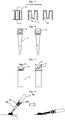
FIG. 6 provides a front view and a side view, showing a blood sampler of a blood sampling device according to the second embodiment of the present invention. A U-shaped projection is disposed on the upper part of the blood sampler. -
FIG. 7 provides a front view and a side view, showing a container of a blood sampling device according to the second embodiment of the present invention. A U-shaped notch is disposed on the upper part of the container. -
FIG. 8 is an explanatory view showing a state in which blood is collected using a blood collection tool in which a blood sampler and a container are combined, using a blood sampling device according to the second embodiment of the present invention. -
FIG. 9 is a cross-sectional view showing a blood sampling device according to the third embodiment of the present invention. -
FIG. 10 shows an embodiment in which an agent is added to a receiving part of a container using a blood sampling device of the present invention. - Hereinafter, a blood sampling device and a blood collection method according to embodiments of the present invention will be described with reference to the drawings.
- The present invention will now be described by way of exemplary embodiments, together with preferred methods and materials that can be used in the practice of the invention. Unless otherwise noted in the text, all technical and scientific terms used in the present specification have the same meaning as commonly understood by one of ordinary skill in the art to which this invention belongs. In addition, any materials and methods equivalent or similar to those described in the present specification can be used as well in the practice of the invention. In addition, all publications and patents cited in this specification in relation to the invention described herein constitute a part of the present specification, for example, as methods, materials and the like that can be used with the invention.
- In blood tests, blood is prepared by centrifugation according to the purpose, and in this specification, the supernatant component obtained by centrifuging a whole blood sample is defined as serum, and the supernatant component obtained in the anticoagulant-added state is defined as plasma. Furthermore, the precipitated component produced by centrifugation performed to obtain serum or plasma is defined as blood cell.
- Hereinafter, a
blood sampling device 100 according to the first embodiment of the present invention will be described with reference toFIGS 1 to 5 . - As shown in
FIG. 1 , theblood sampling device 100 of the present invention is constituted of ablood sampler 10, acontainer 20 and a sealingcap 30. The three parts may constitute a blood sampling device as a set in a separate state, but it is preferable that theblood sampler 10 is accommodated in thecontainer 20 and the sealingcap 30 is set in a state of unity as shown inFIG. 1. FIG. 1 shows the state of theblood sampling device 100 before blood collection according to the present invention. Theblood sampler 10 is inserted into thecontainer 20 and is loosely fixed, and thecontainer 20 and the sealingcap 30 are loosely fitted. The tip of theblood sampler 10 is not in close contact with the bottom surface of the receivingpart 21 of thecontainer 20. Therefore, no load is applied to the bottom opening of theblood sampler 10, and deformation of the bottom opening can be prevented. Further, the projection of the lockingpart 22 of thecontainer 20 and theprojection 32 of the sealing cap are engaged with each other to prevent the sealingcap 30 from coming off. In addition, themandrel 31 of the sealing cap is inserted into the top opening of the blood sampler, and contributes to stability during transportation. -
FIG. 2 shows the state of theblood sampling device 100 of the present invention after blood collection. In this state, theblood sampler 10 after blood collection is placed in thecontainer 20, the sealingcap 30 is fitted, and thecontainer 20 and the sealingcap 30 are screwed together. The bottom opening of theblood sampler 10 is sealed by the close contact between the tip of theblood sampler 10 and the bottom surface of the receivingpart 21 of thecontainer 20. Further, in this state, themandrel 31 of the sealingcap 30 is strongly inserted into the top opening of theblood sampler 10, and the upper inner side of theblood sampler 10 and themandrel 31 come in close contact with each other to seal the top opening of theblood sampler 10. In addition, thecontainer 20 and the sealingcap 30 are screwed together so that the sealed state is sufficient. -
FIG. 3 shows theblood sampler 10. Theblood sampler 10 has a pipette tip shape and is narrowed toward the tip. The internal space of theblood sampler 10 has a bottom opening and a top opening, which are in communication. The lower part of the internal space constitutes ablood holding part 11 that holds blood, and theblood holding part 11 is tapered from the bottom opening toward the top opening. The ratio of the blood holding part in the internal space is not particularly limited as long as it can hold the target amount of blood, but is preferably about 1/30 to 4/5 of the whole, more preferably about 1/10 to 3/5 of the whole, further preferably about 1/5 to 1/2 of the whole. It is preferable that theupper part 12 close to the upper end of theblood sampler 10 has a cylindrical shape so that its inner side can be in close contact with the root part of themandrel 31 of the sealing cap, in addition, its outer side can be easily fitted with the container. In addition, the cylindrical shape can facilitate access to the collected blood from the top opening. On the outer side of theupper part 12 of the blood sampler, aconvex part 13 and aconcave part 14 can be further provided in that order from the tip. Theconvex part 13 and theconcave part 14 are preferably arranged so as to be in opposite positions across the center line. In the side view ofFIG. 3 , theouter periphery 15 of the lower part of theblood sampler 10 corresponding to the part in contact with the vicinity of the upper end of the receivingpart 21 of the container has a shape with no slope. However, it is not necessary to have the outerperipheral part 15 with no slope. - The material of the
blood sampler 10 is not limited, but a hard material with high transparency is preferable in consideration of operability and gripping property during blood collecting, and transportability and the like. The blood sampler is preferably made of a material of a polymer compound such as polyvinyl chloride, polyethylene, polypropylene, acrylonitrile butadiene styrene (ABS), polycarbonate, polyethylene terephthalate and the like from the viewpoint of processability, operability and the like. - The volume of the
blood holding part 11 of theblood sampler 10 is preferably 200 µL or less, more preferably 150 µL or less, and further preferably 100 µL or less. The inner diameter of the bottom opening of theblood sampler 10 and the inner diameter of the body part that is a blood holding part can be arbitrarily determined as long as the effect of the capillary action can be obtained. The inner diameter of the bottom opening of theblood sampler 10 is, for example, but not limited to, 0.1 mm or more and less than 2.0 mm, preferably 0.3 mm or more and less than 1.5 mm, more preferably 0.5 mm or more and less than 1.0 mm, further preferably 0.7 mm or more and less than 0.9 mm. Thereby, blood can be easily collected from the bottom opening by the capillary action. - The
blood holding part 11 has an inner wall preferably subjected to a hydrophilic treatment. When the inner wall is hydrophilically treated, there is an advantage that blood can flow smoothly when blood is collected, and a target amount of blood can be collected easily by combination of the capillary action and the effect of the hydrophilic treatment of the inner wall. The hydrophilic treatment of the inner wall of the blood holding part can be performed using a known method, and hydrophilicity can be imparted by a method including, for example, but not limited to, surface etching, fluorine treatment and introduction of a hydrophilic functional group to the surface via a catalyst. A treatment for imparting hydrophilicity to the surface of a material made of a polymer compound, for example, polypropylene or polycarbonate, is known, and these methods can be used. Although not limited, for example, a method using a mixed gas of a fluorine gas and an oxygen gas or a technique described in Hidehiko Enomoto, Toshiya Murata, Surface Technology, Vol. 59, No. 5, pp. 282-287 (2008) can be used. - An agent can be applied to the inner wall of the
blood sampler 10, preferably to the inner wall of theblood holding part 11, as necessary. By collecting blood in theblood sampler 10 in which an agent has been applied to the inner wall, it is possible to add the agent to blood without separately performing an agent addition operation. - Using the
blood sampler 10, blood can be collected from the bottom opening of the blood sampler by utilizing the capillary action or the weight of the liquid itself. For example, when collecting peripheral blood from a fingertip or earlobe, the fingertip or earlobe is punctured, then, the bottom opening of the blood sampler is brought into contact with the blood that has come out, as a result, the blood is introduced into the blood sampler due to the capillary action or the weight of the liquid itself, thus, blood collection is possible. - In the collection of blood, the amount of blood collection by the blood sampler is not limited, and the amount of blood collected can be changed according to the device used, the agent, the purpose of the test item, and the like. When the blood sampling device of the present invention is used, it is possible to collect an arbitrary small amount of blood, for example, an arbitrary amount from 10 µL to 300 µL.
-
FIG. 4 shows thecontainer 20. Thecontainer 20 has a cylindrical internal space into which theblood sampler 10 can be inserted. The bottom part has a receivingpart 21 into which the lower part of theblood sampler 10 can be inserted. The receivingpart 21 may have a cylindrical shape having substantially the same upper end inner diameter and lower end inner diameter, or may have a shape in which the inner diameter decreases from the upper end to the lower end in accordance with the tip portion of theblood sampler 10. Thecontainer 20 has a lockingpart 22 having a claw-like projection and ascrew part 23 on the upper outer side. The locking part and the screw part are arranged so as to be offset from each other in the vertical direction in that order from the upper end of thecontainer 20. Aconvex part 24 may be further provided on the upper inner side of thecontainer 20. Twoconvex parts 24 are preferably arranged at opposing positions. Thecontainer 20 may further have astopper 25 on the outer side for preventing excessive screwing when the sealing cap and the container are screwed together. Thestopper 25 may be arranged so as to cover the outer peripheral part, or twostoppers 25 may be arranged so as to be in opposite positions across the center line as shown in the drawing. The length or size of the stopper is not particularly limited, and may be as small as a projection as long as it functions as a stopper. - The material of the
container 20 is not limited, but it is preferable that thecontainer 20 is a hard material with high transparency in consideration of operability and gripping property when accommodating the blood sampler, and transportability and the like in accommodation of the blood sampler. The container is preferably made of a material of a polymer compound such as polyvinyl chloride, polyethylene, polypropylene, acrylonitrile butadiene styrene (ABS), polycarbonate, polyethylene terephthalate and the like from the viewpoint of processability, operability and the like. -
FIG. 5 shows the sealingcap 30. The sealingcap 30 has a cap piston shape. Amandrel 31 extends from the inner upper surface of the sealing cap. The upper end of the mandrel may be opened or closed. The shape of the mandrel is not particularly limited, and may be a cylindrical shape in which the diameter of the root part extending from the inside of the sealing cap and the diameter at the tip are approximately the same or may be a stepped shape in which the diameter of the root part is larger than the diameter of the tip, and the latter is preferable. In the latter case, when the blood sampler is accommodated in the container after blood collection, the root part of the mandrel can be brought into closely contact with the upper inner side of the blood sampler and the tip of the mandrel can be strongly pushed into the blood sampler, to improve sealing performance. Aprojection 32 and ascrew part 33 are provided on the inner side surface of the sealing cap. Theprojection 32 and thescrew part 33 are arranged so as to be offset from each other in the vertical direction in that order from the upper end of the sealing cap. - The material of the sealing cap is not limited, but it is preferable that the sealing cap is a hard material with high transparency in consideration of gripping property by the operator, transportability and the like. The sealing cap is preferably made of a material of a polymer compound such as polyvinyl chloride, polyethylene, polypropylene, acrylonitrile butadiene styrene (ABS), polycarbonate, polyethylene terephthalate and the like from the viewpoint of processability, operability and the like.
- The assembly of the
blood sampling device 100 of the present invention before blood collection in a state of unity wherein theblood sampler 10 is accommodated in thecontainer 20 and the sealingcap 30 is set will be described. - As shown in
FIG. 1 , theblood sampling device 100 before blood collection is so constituted that theblood sampler 10 is inserted into thecontainer 20, theblood sampler 10 is loosely fixed in thecontainer 20, and further, the sealingcap 30 is loosely fitted to thecontainer 20. Aconvex part 13 and aconcave part 14 may be provided on the upper outer side of the blood sampler, and aconvex part 24 may be provided on the upper inner side of the container. In such a case, when theblood sampler 10 is inserted into thecontainer 20, theconvex part 13 of the blood sampler collides with theconvex part 14 of the container, thereby preventing the blood sampler from being excessively inserted into the container, and the blood sampler can be easily loosely fitted into the container. After inserting theblood sampler 10 into thecontainer 20, if thescrew part 23 of thecontainer 20 and thescrew part 33 of the sealingcap 30 or the lockingpart 22 and theprojection 32 are aligned and the sealingcap 30 is fitted in thecontainer 20, theprojection 32 on the inner side of the sealing cap collides with the lockingpart 22 on the outer side of the container. When the sealing cap is further pushed in, thescrew part 33 on the inner side of the sealing cap collides with thescrew part 23 on the outer side of the container to serve as a stopper, thereby preventing the sealing cap from being pushed further. In this state, theprojection 32 and the lockingpart 22 are engaged with each other, thus, it serves to prevent the sealing cap from coming off, and thecontainer 20 and the sealingcap 30 are loosely fixed to each other. Further, themandrel 31 extending from the inner upper surface of the sealing cap is located in the upper part of the internal space of theblood sampler 10. As described above, theblood sampling device 100 before blood collection can be configured in a state in which the sealing cap is not dropped off and the blood sampler, the container and the sealing cap are loosely fitted, thus, since they are grouped together, the handling of the device is easy. - For the
blood sampling device 100 of the present invention, three parts: theblood sampler 10, thecontainer 20 and the sealingcap 30 may be placed in a separate state before blood collection, and this configuration is also included in the blood sampling device of the present invention. In such a case, it is preferable that those parts are stored in a case or the like that can fix those parts. - Next, blood collection will be described. For blood collection, the
blood sampler 10 is taken out from theblood sampling device 100 before blood collection, alternatively, when parts are stored in a separate state in a case, theblood sampler 10 is taken out from the case, and the tip can be brought into contact with blood, to carry out blood collection. The blood collection with theblood sampler 10 will be described with reference toFIG 8 . Although the drawing shows blood collection when theblood sampler 10 and thecontainer 20 are combined, the same shall apply to the case where only theblood sampler 10 is used. - Blood collection using the
blood sampler 10 can be performed by picking the outer periphery of the top opening of the blood sampler with fingers and bringing the bottom opening into contact with blood. Alternatively, as shown inFIG. 8 , by fitting the upper end of the blood sampler to the upper end of the container while the blood sampler is turned upside down, a blood collection tool for collecting blood consisting of theblood sampler 10 and thecontainer 20 is provided. In such a blood collection tool, blood can be collected by picking the outer periphery of the container with fingers and bringing the bottom opening into contact with blood, so it is easier to handle. - When blood is collected, by bringing the tip of the
blood sampler 10 into contact withblood 1, blood suction is started by the capillary action and/or the weight of the liquid itself, and the blood is aspirated and filled in theblood holding part 11, as shown inFIG. 8 . In the figure, theblood sampler 10 is tilted horizontally, this makes it possible to collect a larger amount of blood more easily. However, if a target amount of blood can be collected, it does not have to be tilted. The blood collected using the blood sampling device of the present invention is preferably peripheral blood. - The amount of blood to be collected can be changed according to the intended examination and measurement, and the length and diameter of the
blood holding part 11 can be adjusted accordingly. For example, the amount of blood to be collected can be adjusted, but not limited thereto, in the range of 10 µL to 300 µL, preferably 10 µL to 200 µL, more preferably 50 µL to 100 µL. Further, by providing the blood sampler with a guide line indicating that a specific amount of blood has been collected, it is possible to accurately collect a specific amount of blood. - The collected blood is held in the
blood holding part 11. The hollow structure inside theblood holding part 11 has a taper shape, and this taper shape improves the suction of blood by inducing the weight of the liquid itself in addition to the capillary action when blood is collected from the lower part. Theblood holding part 11 has a capillary action and a function of the weight of the liquid itself, and may have any outer shape, inner shape and material as long as the blood can be collected from the upper part, and by using a hydrophilic material or a hydrophilically-treated material on the inner surface, a better capillary action can be achieved. - After collecting blood, the
blood sampler 10 is inserted into thecontainer 20. After blood collection, by strongly pushing the blood sampler into the container, the lower part of the blood sampler is fitted into the receivingpart 21 of the container and the upper part of the blood sampler is fitted to the upper inner side of the container. If the receivingpart 21 has a cylindrical shape having approximately the same upper end inner diameter and lower end inner diameter, the vicinity of the upper end of the receivingpart 21 and a part of the lower part of theblood sampler 10 may come into close contact and may be fitted with each other. In such a case, theouter periphery 15 at the lower part of theblood sampler 10 corresponding to the part in contact with the vicinity of the upper end of the receivingpart 21 can be formed into a shape having no slope in order to ensure the close contact. When theconvex part 13 and theconcave part 14 are provided on the upper outer side of the blood sampler and theconvex part 24 is provided on the upper inner side of the container, theconcave part 14 and theconvex part 24 are fitted together by inserting theblood sampler 10 into thecontainer 20 and pressing it strongly. Next, the sealingcap 30 is fitted and further screwed. In this state, the bottom opening of the blood sampler is completely closed by the receivingpart 21, while the top opening is completely closed by themandrel 31 of the sealing cap, and the blood sampler holding blood in the blood holding part is completely sealed.FIG. 2 shows the blood sampling device in this mode. - Even if the
blood sampler 10 after blood collection is not pushed strongly into thecontainer 20, by fitting and further screwing the sealingcap 30, the lower part of the blood sampler is fitted into the receivingpart 21 of the container and the upper part of the blood sampler is fitted to the upper inner side of the container, and the bottom opening of the blood sampler is closed completely by the receivingpart 21 and the top opening is closed completely by the mandrel of the sealing cap, to completely seal the blood sampler holding blood in the blood holding part. -
FIG. 6 and FIG. 7 are views showing theblood sampler 10 and thecontainer 20 of the second embodiment of theblood sampling device 100 according to the present invention. In the second embodiment, theblood sampler 10 has aU-shaped projection 16 at the top thereof, while thecontainer 20 has aU-shaped notch 26 that fits with theprojection 16 at the top thereof. Preferably, twoU-shaped projections 16 and twoU-shaped notches 26 are arranged, respectively. With this configuration, in theblood sampling device 100 before blood collection, a part of theU-shaped projection 16 and a part of theU-shaped notch 26 are engaged, to help loose fixation of the blood sampler and the container. Then, in theblood sampling device 100 after blood collection, theU-shaped projection 16 and theU-shaped notch 26 are engaged to help the blood sampler and the container to be firmly fixed. - In blood collection in the blood sampling device according to the second embodiment, by taking the
blood sampler 10 out of thecontainer 20 and turning it upside down and inserting the U-shaped projection of theblood sampler 10 into the U-shaped notch of thecontainer 20, a blood collection tool in which a part of the U-shaped projection and a part of the U-shaped notch are fitted to each other can be produced. A blood collection tool in which theblood sampler 10 and thecontainer 20 are combined can be easily grasped and can collect blood by an easier operation. However, in theblood sampling device 100 of the second embodiment, blood can also be collected using only theblood sampler 10. -
FIG. 9 is a view showing the third embodiment of theblood sampling device 100 according to the present invention. In the third embodiment, the bottom surface of the receivingpart 21 of thecontainer 20 is provided with aprojection 27 that matches the diameter of the bottom opening of theblood sampler 10. The blood sampling device of the present invention before blood collection is in a state where theblood sampler 10 is inserted into thecontainer 20 and is loosely fixed and thecontainer 20 and the sealingcap 30 are loosely fitted, thus, the bottom opening of theblood sampler 10 is not in close contact with the projection. Therefore, even if it is stored and transported in a unit state before blood collection, the deformation of the projection can be prevented. After blood collection, in a state where theblood sampler 10 is inserted into thecontainer 20 and the sealingcap 30 is fitted and screwed together, theprojection 27 is inserted into the bottom opening of theblood sampler 10 and the bottom opening comes into close contact with theprojection 27. As a result, better sealing can be achieved. - The blood sampling device of the present invention can be stored and/or transported with a blood sampler containing blood inserted in the container. Moreover, the blood sampling device of the present invention can be subjected to a centrifugal separation operation in a state where the blood sampler is inserted into the container. Thereby, the blood can be centrifuged in a state where the blood is held in the blood sampling device of the present invention, and separated into serum or plasma and blood cells, and the device can be stored and/or transported as it is. Furthermore, with the blood sampling device of the present invention, a centrifugal separation operation is conducted, then, the sealing cap is opened, and the resultant supernatant (serum or plasma) can be collected by a collecting means (for example, a micropipette).
- The
blood sampling device 100 of the present invention has a configuration in which theblood sampler 10 that has collected blood is inserted into thecontainer 20 and the sealingcap 30 is fitted and screwed, so that the blood is sealed and sufficient sealing is attained not only under atmospheric pressure but also under negative pressure. Further, in this state, it can be stored or transported, and further, it can also be centrifuged. - In the
blood sampling device 100 of the present invention, an agent can be added to the receivingpart 21 in advance according to the blood collecting conditions. When theblood sampler 10 that has collected blood is inserted into thecontainer 20 and pushed in, or when theblood sampler 10 that has collected blood is inserted into thecontainer 20 and the sealing cap is fitted and screwed, theagent 29 flows in the blood sampler, then, the tip of the blood sampler is sealed. Thereby, the blood to which the agent is added can be prepared without separately performing an agent addition operation. As shown inFIG. 10 , when theagent 29 is held in the receivingpart 21, it is preferable to provide alock mechanism 28 in the receiving part. By providing the lock mechanism, when the tip of theblood sampler 10 is inserted into the receivingpart 21 of thecontainer 20, the leakage of the agent into the container can be prevented and the inflow of the agent into the blood sampler can be sufficient. - The agent is appropriately selected according to the purpose, and includes, for example, but not limited to, a separating agent. The type of the separating agent that can be used in the present invention is not particularly limited, and includes those composed mainly of, for example, silicon, α-olefin-maleic acid ester, polyester polymer, acrylic polymer, chlorinated polybutene and cyclopentadiene resins, or modified cyclopentadiene resins obtained by introducing a hydroxyl group, an ester group, an ether group, an epoxy group and the like into cyclopentadiene resins, and the like.
- In the
blood sampling device 100 of the present invention, it is possible that an agent is applied in advance to the inner wall of theblood sampler 10, preferably to the inner wall of theblood holding part 11 in accordance with the blood collecting conditions. The agent that can be applied is appropriately selected according to the purpose and includes, for example, but not limited to, an anticoagulant, a procoagulant and a glycolytic inhibitor. For example, the anticoagulant may be added for the purpose of collecting plasma, the procoagulant may be added for the purpose of shortening the clotting time when collecting serum, and the glycolytic inhibitor may be added to consume glucose in blood when cells such as red blood cells are present, and to inhibit glycolysis thereof. - When blood is collected using the
blood sampler 10, the blood comes into contact with the agent applied to the inner wall, and the agent diffuses into the blood. In order to promote mixing of the agent and blood, it is preferable to insert theblood sampler 10 into thecontainer 20 and screw the sealingcap 30, then, to invert the device to mix them. The number of times of inversion mixing is not particularly limited as long as mixing can be sufficiently achieved, and it is usually performed several times, preferably 5 times or more. By applying the agent to the inner wall, it is possible to prepare blood to which the agent has been added without separately performing an agent addition operation after blood collection. - In the embodiment added with the anticoagulant in the present invention, the coagulation of blood is inhibited by the anticoagulant, so it can be stored or transported immediately after blood collection without separating plasma and blood cells by centrifugation. It is also possible to separate the plasma and blood cells by centrifugation. The type of the anticoagulant that can be used in the present invention is not particularly limited, and examples thereof include ethylenediaminetetraacetic acid (EDTA) alkali metal salts, heparin alkali metal salts, or sodium citrate and the like.
- The type of the procoagulant that can be used in the present invention is not particularly limited, and examples thereof include silica fine particles, thrombin and the like.
- The type of the glycolytic inhinbitor that can be used in this invention is not particularly limited, and examples thereof include sodium fluoride and the like.
- In the
blood sampling device 100 of the present invention, information for identifying theblood sampling device 100 may be added to thecontainer 20 or the sealingcap 30 as long as the collected blood is not affected. For example, information can be added to theblood sampling device 100 after blood collection or before blood collection, by attaching a sticker printed with an ID or a one-dimensional bar-code produced based on the ID to thecontainer 20 or the sealingcap 30, for identifying eachblood sampling device 100. - When the blood sampling device of the present invention is used, good blood suitable for blood analysis can be prepared even with a small amount of peripheral blood collected from a fingertip or earlobe and the like. Such a blood can be diluted and analyzed by a conventional protocol used for analysis of brachial venous blood collected with a conventional blood collection tube or the like, a method reported by the inventors (see, e.g., Hajime Iwasawa et al., Correlation of the blood test results obtained between assays using microliter-scale fingertip blood samples collected with a novel blood collection device and conventional venous blood assays, Clinical Pathology 2017; 65 (3): 252-259. and Shihoko Namba et al., A New Hepatitis Virus Test with Microliter-scale Fingertip Blood Collection in Japan, Acta Med. Okayama 208; 72 (3): 283-287) and the like, or with an existing analyzer. That is, blood analysis similar to the conventional one can be performed using a small amount of peripheral blood collected from a fingertip or earlobe. Although not limited thereto, for example, when 60 µL of whole blood is collected from a fingertip and serum or plasma is prepared using the blood sampling device of the present invention, about 30 µL of serum or plasma can be obtained. When this is diluted 10-fold with a dilution buffer (for example, physiological saline), a 300 µL blood sample can be prepared. Using this, normal biochemical analysis of blood can be performed. That is, the present invention is also a blood sampling device which can be used for conducting blood analysis using a small amount (for example, 300 µL or less, preferably 100 µL or less, more preferably 60 µL or less) of peripheral blood collected from a fingertip or earlobe. For example, blood collected using the blood sampling device of the present invention can also be used for special test items such as cancer markers and allergies, in addition to general biochemical item and/or immune item tests commonly used in blood tests, so-called blood biochemical tests.
- The above detailed description is merely illustrative of the objects and subjects of the present invention and is not intended to limit the scope of the appended claims. Various changes and substitutions to the described embodiments will be apparent to those skilled in the art from the teachings set forth in the present specification without departing from the scope of the appended claims.
-
- 1.
- blood
- 10.
- blood sampler
- 11.
- blood holding part
- 12.
- blood sampler upper part
- 13.
- blood sampler convex part
- 14.
- blood sampler concave part
- 15.
- blood sampler lower periphery
- 16.
- U-shaped projection
- 20.
- container
- 21.
- receiving part
- 22.
- locking part
- 23.
- screw part
- 26.
- U-shaped notch
- 27.
- projection
- 28.
- lock mechanism
- 29.
- agent
- 30.
- sealing cap
- 31.
- mandrel
- 32.
- projection
- 33.
- screw part
- 100.
- blood sampling device
Claims (13)
- A blood sampling device comprising a pipette tip-shaped blood sampler having an internal space for holding blood after aspirating the blood and having openings at the top and bottom, a cylindrical container capable of accommodating the blood sampler and a cap piston-shaped sealing cap for sealing the container, wherein
the internal space of the blood sampler is so configured that the bottom opening and the top opening communicate, the lower part of the internal space constituting the blood holding part has a tapered shape from the bottom opening toward the top opening, and blood is aspirated into the internal space by the capillary action when the bottom opening is brought into contact with blood,
the container has an internal space into which the blood sampler can be inserted and a receiving part at the bottom into which the tip of the blood sampler can be inserted, and a locking part having a claw-like projection and a screw part are provided on the upper outer side of the container and the locking part and the screw part are arranged to be offset from each other in the vertical direction in that order from the top of the container, and
the sealing cap has a mandrel extending from the inner upper surface of the sealing cap to the internal space of the blood sampler, and a projection that engages with the projection of the locking part of the container and a screw part that can be screwed into the screw part of the container are provided on the inner side surface of the sealing cap and the projection and the screw part are arranged to be offset from each other in the vertical direction in that order from the top of the sealing cap. - The blood sampling device according to Claim 1, wherein the locking part and the screw part of the container and the projection and the screw part of the sealing cap are configured so that when the sealing cap is attached to the upper end of the container, the screw part of the sealing cap and the screw part of the container come into contact with each other and serve as a stopper by which the container cannot be inserted into the sealing cap any more, and the projection of the locking part engages with the projection of the sealing cap to prevent the sealing cap from coming off, and the sealing cap is loosely fitted to the upper end of the container.
- The blood sampling device according to Claim 1, configured so that, when the sealing cap is fitted into the upper part of the container and then the screw part of the sealing cap and the screw part of the container are screwed together under condition where the blood sampler that has collected blood is inserted into the container, the tip of the blood sampler is further fitted into the receiving part of the container and the mandrel of the sealing cap is inserted into the top opening of the blood sampler to close the top opening and the bottom opening of the blood sampler and to seal the container into which the blood sampler holding blood is inserted.
- The blood sampling device according to any one of Claims 1 to 3, wherein two locking parts and two screw parts are arranged at the upper part of the container and two projections and two screw parts are arranged on the sealing cap, respectively.
- The blood sampling device according to any one of Claims 1 to 4, wherein the blood sampler has a U-shaped projection at the upper part, and the container has a U-shaped notch that fits to the U-shaped projection at the upper part.
- The blood sampling device according to any one of Claims 1 to 5, wherein the inner wall of the lower part of the internal space of the blood sampler constituting the blood holding part is hydrophilically treated.
- The blood sampling device according to Claim 6, wherein the hydrophilic treatment of the blood sampler is performed by etching or fluorine treatment.
- The blood sampling device according to any one of Claims 1 to 7, wherein the bottom opening of the blood sampler is an opening having an inner diameter of 0.5 mm or more and less than 1.0 mm.
- The blood sampling device according to any one of Claims 1 to 8, wherein the bottom surface of the receiving part of the container has a projection that fits into the bottom opening of the blood sampler.
- The blood sampling device according to any one of Claims 1 to 9, wherein an agent is added in the receiving part of the container.
- The blood sampling device according to Claim 10, wherein the agent is a separating agent.
- The blood sampling device according to any one of Claims 1 to 9, wherein an agent is applied to the inner wall of the blood holding part of the blood sampler.
- The blood sampling device according to Claim 12, wherein the agent is selected from the group consisting of anticoagulants, procoagulants and glycolytic inhibitors.
Applications Claiming Priority (2)
| Application Number | Priority Date | Filing Date | Title |
|---|---|---|---|
| JP2018161403A JP6444560B1 (en) | 2018-08-30 | 2018-08-30 | Blood collection device |
| PCT/JP2019/023139 WO2020044722A1 (en) | 2018-08-30 | 2019-06-11 | Blood collecting instrument |
Publications (3)
| Publication Number | Publication Date |
|---|---|
| EP3644057A1 true EP3644057A1 (en) | 2020-04-29 |
| EP3644057A4 EP3644057A4 (en) | 2021-01-27 |
| EP3644057B1 EP3644057B1 (en) | 2021-08-11 |
Family
ID=64899454
Family Applications (1)
| Application Number | Title | Priority Date | Filing Date |
|---|---|---|---|
| EP19797976.8A Active EP3644057B1 (en) | 2018-08-30 | 2019-06-11 | Blood collecting instrument |
Country Status (7)
| Country | Link |
|---|---|
| US (1) | US11622706B2 (en) |
| EP (1) | EP3644057B1 (en) |
| JP (1) | JP6444560B1 (en) |
| KR (1) | KR102289674B1 (en) |
| CN (1) | CN111133311B (en) |
| SG (1) | SG11201910487QA (en) |
| WO (1) | WO2020044722A1 (en) |
Families Citing this family (9)
| Publication number | Priority date | Publication date | Assignee | Title |
|---|---|---|---|---|
| US12059675B2 (en) | 2019-11-26 | 2024-08-13 | Yokogawa Electric Corporation | Tip device, tip container set, tip electrode apparatus, and tip electrode set |
| JP7230854B2 (en) * | 2020-02-28 | 2023-03-03 | 株式会社三洋物産 | game machine |
| JP7230859B2 (en) * | 2020-02-28 | 2023-03-06 | 株式会社三洋物産 | game machine |
| JP7230858B2 (en) * | 2020-02-28 | 2023-03-06 | 株式会社三洋物産 | game machine |
| JP7230855B2 (en) * | 2020-02-28 | 2023-03-03 | 株式会社三洋物産 | game machine |
| JP7230856B2 (en) * | 2020-02-28 | 2023-03-03 | 株式会社三洋物産 | game machine |
| CN116851052B (en) * | 2023-08-31 | 2025-07-22 | 江苏科华医疗器械科技有限公司 | Closed type dropper device for detection and application method thereof |
| JP2025128682A (en) * | 2024-02-22 | 2025-09-03 | 株式会社Provigate | Fingertip blood sampling kit |
| CN118225510B (en) * | 2024-05-27 | 2024-07-30 | 济南原子高科医药有限公司 | Radiopharmaceutical sampling device |
Family Cites Families (11)
| Publication number | Priority date | Publication date | Assignee | Title |
|---|---|---|---|---|
| NL179870C (en) * | 1974-08-16 | 1986-12-01 | Sarstedt Kunststoff | BARREL FOR TAKING BLOOD WITH A CAPILLARY MOUTH. |
| JP4007639B2 (en) | 1997-05-19 | 2007-11-14 | 株式会社荏原製作所 | Sewage return water treatment method and equipment |
| EP1909089A1 (en) * | 2005-06-08 | 2008-04-09 | Nipro Corporation | Specimen sampling liquid container |
| JP4943269B2 (en) * | 2007-08-09 | 2012-05-30 | 株式会社ミズホメディー | Sample extraction container |
| EP2364218B1 (en) * | 2008-10-31 | 2020-04-15 | Biomerieux, Inc | Container for the isolation and identification of microorganisms |
| JP6704851B2 (en) * | 2014-01-20 | 2020-06-03 | アボゲン,インコーポレイティド | Devices, solutions, and methods for sample collection |
| WO2016073832A1 (en) * | 2014-11-07 | 2016-05-12 | Theranos, Inc. | Improved methods, devices, and systems for mixing fluids |
| JP6104480B2 (en) * | 2015-03-17 | 2017-04-05 | 株式会社エム・ビー・エス | Sampling separation device |
| DE102016002588A1 (en) * | 2016-03-03 | 2017-09-07 | Kathrein-Werke Kg | cellular antenna |
| ITUA20161845A1 (en) * | 2016-03-21 | 2017-09-21 | Kaltek S R L | CONTAINMENT DEVICE FOR BIOLOGICAL SAMPLES |
| JP6104440B1 (en) | 2016-08-17 | 2017-03-29 | 株式会社エム・ビー・エス | Blood collection device including blood collection device and blood container |
-
2018
- 2018-08-30 JP JP2018161403A patent/JP6444560B1/en active Active
-
2019
- 2019-06-11 WO PCT/JP2019/023139 patent/WO2020044722A1/en not_active Ceased
- 2019-06-11 KR KR1020197033683A patent/KR102289674B1/en active Active
- 2019-06-11 CN CN201980002394.5A patent/CN111133311B/en active Active
- 2019-06-11 EP EP19797976.8A patent/EP3644057B1/en active Active
- 2019-06-11 US US16/610,402 patent/US11622706B2/en active Active
- 2019-06-11 SG SG11201910487QA patent/SG11201910487QA/en unknown
Also Published As
| Publication number | Publication date |
|---|---|
| KR102289674B1 (en) | 2021-08-13 |
| SG11201910487QA (en) | 2020-04-29 |
| US20220257156A1 (en) | 2022-08-18 |
| WO2020044722A1 (en) | 2020-03-05 |
| KR20200026181A (en) | 2020-03-10 |
| EP3644057B1 (en) | 2021-08-11 |
| CN111133311A (en) | 2020-05-08 |
| EP3644057A4 (en) | 2021-01-27 |
| CN111133311B (en) | 2023-10-13 |
| JP2020034427A (en) | 2020-03-05 |
| JP6444560B1 (en) | 2018-12-26 |
| US11622706B2 (en) | 2023-04-11 |
Similar Documents
| Publication | Publication Date | Title |
|---|---|---|
| EP3644057B1 (en) | Blood collecting instrument | |
| US10730043B2 (en) | Sample collection and separation device | |
| CN106456075B (en) | Sampling and assay kits, sample holders and methods | |
| EP2986218B1 (en) | Biological fluid collection device and biological fluid separation and testing system | |
| CA3005826C (en) | Biological fluid collection device and biological fluid separation and testing system | |
| EP1012560B1 (en) | Method for collecting samples of liquid specimens for analytical testing | |
| US5924594A (en) | Collection container assembly | |
| JP6104440B1 (en) | Blood collection device including blood collection device and blood container | |
| JP2011502623A (en) | Transdermal body fluid sampling and pretreatment apparatus and method | |
| CA2909231C (en) | Biological fluid collection device and biological fluid separation system | |
| WO1999008095A1 (en) | Analytical cartridge | |
| US20020156439A1 (en) | Collection container assembly | |
| US20100172797A1 (en) | Extraction method and apparatus for high-sensitivity body fluid testing device | |
| RU2744488C1 (en) | Analyzer cartridge with capillary cleaner | |
| WO2019107509A1 (en) | Blood test container | |
| US20060216829A1 (en) | Erythrocyte sedimentation rate (ESR) test measurement instrument of unitary design and method of using the same | |
| GB2051359A (en) | A sample or reagent container for automatic analysis apparatus | |
| JP3597827B2 (en) | Biological sample separation device and separation method therefor | |
| JPS59187263A (en) | Blood separation tube |
Legal Events
| Date | Code | Title | Description |
|---|---|---|---|
| STAA | Information on the status of an ep patent application or granted ep patent |
Free format text: STATUS: UNKNOWN |
|
| STAA | Information on the status of an ep patent application or granted ep patent |
Free format text: STATUS: THE INTERNATIONAL PUBLICATION HAS BEEN MADE |
|
| PUAI | Public reference made under article 153(3) epc to a published international application that has entered the european phase |
Free format text: ORIGINAL CODE: 0009012 |
|
| STAA | Information on the status of an ep patent application or granted ep patent |
Free format text: STATUS: REQUEST FOR EXAMINATION WAS MADE |
|
| 17P | Request for examination filed |
Effective date: 20191113 |
|
| AK | Designated contracting states |
Kind code of ref document: A1 Designated state(s): AL AT BE BG CH CY CZ DE DK EE ES FI FR GB GR HR HU IE IS IT LI LT LU LV MC MK MT NL NO PL PT RO RS SE SI SK SM TR |
|
| AX | Request for extension of the european patent |
Extension state: BA ME |
|
| A4 | Supplementary search report drawn up and despatched |
Effective date: 20210113 |
|
| RIC1 | Information provided on ipc code assigned before grant |
Ipc: B01L 3/00 20060101ALI20201222BHEP Ipc: B01L 3/02 20060101ALI20201222BHEP Ipc: G01N 33/48 20060101AFI20201222BHEP Ipc: A61B 5/15 20060101ALI20201222BHEP |
|
| GRAJ | Information related to disapproval of communication of intention to grant by the applicant or resumption of examination proceedings by the epo deleted |
Free format text: ORIGINAL CODE: EPIDOSDIGR1 |
|
| STAA | Information on the status of an ep patent application or granted ep patent |
Free format text: STATUS: GRANT OF PATENT IS INTENDED |
|
| GRAP | Despatch of communication of intention to grant a patent |
Free format text: ORIGINAL CODE: EPIDOSNIGR1 |
|
| GRAJ | Information related to disapproval of communication of intention to grant by the applicant or resumption of examination proceedings by the epo deleted |
Free format text: ORIGINAL CODE: EPIDOSDIGR1 |
|
| STAA | Information on the status of an ep patent application or granted ep patent |
Free format text: STATUS: REQUEST FOR EXAMINATION WAS MADE |
|
| GRAJ | Information related to disapproval of communication of intention to grant by the applicant or resumption of examination proceedings by the epo deleted |
Free format text: ORIGINAL CODE: EPIDOSDIGR1 |
|
| GRAP | Despatch of communication of intention to grant a patent |
Free format text: ORIGINAL CODE: EPIDOSNIGR1 |
|
| GRAP | Despatch of communication of intention to grant a patent |
Free format text: ORIGINAL CODE: EPIDOSNIGR1 |
|
| STAA | Information on the status of an ep patent application or granted ep patent |
Free format text: STATUS: GRANT OF PATENT IS INTENDED |
|
| DAV | Request for validation of the european patent (deleted) | ||
| DAX | Request for extension of the european patent (deleted) | ||
| INTG | Intention to grant announced |
Effective date: 20210512 |
|
| INTC | Intention to grant announced (deleted) | ||
| INTG | Intention to grant announced |
Effective date: 20210604 |
|
| GRAS | Grant fee paid |
Free format text: ORIGINAL CODE: EPIDOSNIGR3 |
|
| GRAA | (expected) grant |
Free format text: ORIGINAL CODE: 0009210 |
|
| STAA | Information on the status of an ep patent application or granted ep patent |
Free format text: STATUS: THE PATENT HAS BEEN GRANTED |
|
| AK | Designated contracting states |
Kind code of ref document: B1 Designated state(s): AL AT BE BG CH CY CZ DE DK EE ES FI FR GB GR HR HU IE IS IT LI LT LU LV MC MK MT NL NO PL PT RO RS SE SI SK SM TR |
|
| REG | Reference to a national code |
Ref country code: CH Ref legal event code: EP |
|
| REG | Reference to a national code |
Ref country code: DE Ref legal event code: R096 Ref document number: 602019006852 Country of ref document: DE |
|
| REG | Reference to a national code |
Ref country code: IE Ref legal event code: FG4D Ref country code: AT Ref legal event code: REF Ref document number: 1419891 Country of ref document: AT Kind code of ref document: T Effective date: 20210915 |
|
| REG | Reference to a national code |
Ref country code: LT Ref legal event code: MG9D |
|
| REG | Reference to a national code |
Ref country code: NL Ref legal event code: MP Effective date: 20210811 |
|
| REG | Reference to a national code |
Ref country code: AT Ref legal event code: MK05 Ref document number: 1419891 Country of ref document: AT Kind code of ref document: T Effective date: 20210811 |
|
| PG25 | Lapsed in a contracting state [announced via postgrant information from national office to epo] |
Ref country code: ES Free format text: LAPSE BECAUSE OF FAILURE TO SUBMIT A TRANSLATION OF THE DESCRIPTION OR TO PAY THE FEE WITHIN THE PRESCRIBED TIME-LIMIT Effective date: 20210811 Ref country code: SE Free format text: LAPSE BECAUSE OF FAILURE TO SUBMIT A TRANSLATION OF THE DESCRIPTION OR TO PAY THE FEE WITHIN THE PRESCRIBED TIME-LIMIT Effective date: 20210811 Ref country code: RS Free format text: LAPSE BECAUSE OF FAILURE TO SUBMIT A TRANSLATION OF THE DESCRIPTION OR TO PAY THE FEE WITHIN THE PRESCRIBED TIME-LIMIT Effective date: 20210811 Ref country code: BG Free format text: LAPSE BECAUSE OF FAILURE TO SUBMIT A TRANSLATION OF THE DESCRIPTION OR TO PAY THE FEE WITHIN THE PRESCRIBED TIME-LIMIT Effective date: 20211111 Ref country code: AT Free format text: LAPSE BECAUSE OF FAILURE TO SUBMIT A TRANSLATION OF THE DESCRIPTION OR TO PAY THE FEE WITHIN THE PRESCRIBED TIME-LIMIT Effective date: 20210811 Ref country code: LT Free format text: LAPSE BECAUSE OF FAILURE TO SUBMIT A TRANSLATION OF THE DESCRIPTION OR TO PAY THE FEE WITHIN THE PRESCRIBED TIME-LIMIT Effective date: 20210811 Ref country code: NO Free format text: LAPSE BECAUSE OF FAILURE TO SUBMIT A TRANSLATION OF THE DESCRIPTION OR TO PAY THE FEE WITHIN THE PRESCRIBED TIME-LIMIT Effective date: 20211111 Ref country code: PT Free format text: LAPSE BECAUSE OF FAILURE TO SUBMIT A TRANSLATION OF THE DESCRIPTION OR TO PAY THE FEE WITHIN THE PRESCRIBED TIME-LIMIT Effective date: 20211213 Ref country code: FI Free format text: LAPSE BECAUSE OF FAILURE TO SUBMIT A TRANSLATION OF THE DESCRIPTION OR TO PAY THE FEE WITHIN THE PRESCRIBED TIME-LIMIT Effective date: 20210811 Ref country code: HR Free format text: LAPSE BECAUSE OF FAILURE TO SUBMIT A TRANSLATION OF THE DESCRIPTION OR TO PAY THE FEE WITHIN THE PRESCRIBED TIME-LIMIT Effective date: 20210811 |
|
| PG25 | Lapsed in a contracting state [announced via postgrant information from national office to epo] |
Ref country code: PL Free format text: LAPSE BECAUSE OF FAILURE TO SUBMIT A TRANSLATION OF THE DESCRIPTION OR TO PAY THE FEE WITHIN THE PRESCRIBED TIME-LIMIT Effective date: 20210811 Ref country code: LV Free format text: LAPSE BECAUSE OF FAILURE TO SUBMIT A TRANSLATION OF THE DESCRIPTION OR TO PAY THE FEE WITHIN THE PRESCRIBED TIME-LIMIT Effective date: 20210811 Ref country code: GR Free format text: LAPSE BECAUSE OF FAILURE TO SUBMIT A TRANSLATION OF THE DESCRIPTION OR TO PAY THE FEE WITHIN THE PRESCRIBED TIME-LIMIT Effective date: 20211112 |
|
| PG25 | Lapsed in a contracting state [announced via postgrant information from national office to epo] |
Ref country code: NL Free format text: LAPSE BECAUSE OF FAILURE TO SUBMIT A TRANSLATION OF THE DESCRIPTION OR TO PAY THE FEE WITHIN THE PRESCRIBED TIME-LIMIT Effective date: 20210811 |
|
| PG25 | Lapsed in a contracting state [announced via postgrant information from national office to epo] |
Ref country code: DK Free format text: LAPSE BECAUSE OF FAILURE TO SUBMIT A TRANSLATION OF THE DESCRIPTION OR TO PAY THE FEE WITHIN THE PRESCRIBED TIME-LIMIT Effective date: 20210811 |
|
| REG | Reference to a national code |
Ref country code: DE Ref legal event code: R097 Ref document number: 602019006852 Country of ref document: DE |
|
| PG25 | Lapsed in a contracting state [announced via postgrant information from national office to epo] |
Ref country code: SM Free format text: LAPSE BECAUSE OF FAILURE TO SUBMIT A TRANSLATION OF THE DESCRIPTION OR TO PAY THE FEE WITHIN THE PRESCRIBED TIME-LIMIT Effective date: 20210811 Ref country code: SK Free format text: LAPSE BECAUSE OF FAILURE TO SUBMIT A TRANSLATION OF THE DESCRIPTION OR TO PAY THE FEE WITHIN THE PRESCRIBED TIME-LIMIT Effective date: 20210811 Ref country code: RO Free format text: LAPSE BECAUSE OF FAILURE TO SUBMIT A TRANSLATION OF THE DESCRIPTION OR TO PAY THE FEE WITHIN THE PRESCRIBED TIME-LIMIT Effective date: 20210811 Ref country code: EE Free format text: LAPSE BECAUSE OF FAILURE TO SUBMIT A TRANSLATION OF THE DESCRIPTION OR TO PAY THE FEE WITHIN THE PRESCRIBED TIME-LIMIT Effective date: 20210811 Ref country code: CZ Free format text: LAPSE BECAUSE OF FAILURE TO SUBMIT A TRANSLATION OF THE DESCRIPTION OR TO PAY THE FEE WITHIN THE PRESCRIBED TIME-LIMIT Effective date: 20210811 Ref country code: AL Free format text: LAPSE BECAUSE OF FAILURE TO SUBMIT A TRANSLATION OF THE DESCRIPTION OR TO PAY THE FEE WITHIN THE PRESCRIBED TIME-LIMIT Effective date: 20210811 |
|
| PLBE | No opposition filed within time limit |
Free format text: ORIGINAL CODE: 0009261 |
|
| STAA | Information on the status of an ep patent application or granted ep patent |
Free format text: STATUS: NO OPPOSITION FILED WITHIN TIME LIMIT |
|
| 26N | No opposition filed |
Effective date: 20220512 |
|
| PG25 | Lapsed in a contracting state [announced via postgrant information from national office to epo] |
Ref country code: IT Free format text: LAPSE BECAUSE OF FAILURE TO SUBMIT A TRANSLATION OF THE DESCRIPTION OR TO PAY THE FEE WITHIN THE PRESCRIBED TIME-LIMIT Effective date: 20210811 |
|
| PG25 | Lapsed in a contracting state [announced via postgrant information from national office to epo] |
Ref country code: SI Free format text: LAPSE BECAUSE OF FAILURE TO SUBMIT A TRANSLATION OF THE DESCRIPTION OR TO PAY THE FEE WITHIN THE PRESCRIBED TIME-LIMIT Effective date: 20210811 |
|
| PG25 | Lapsed in a contracting state [announced via postgrant information from national office to epo] |
Ref country code: MC Free format text: LAPSE BECAUSE OF FAILURE TO SUBMIT A TRANSLATION OF THE DESCRIPTION OR TO PAY THE FEE WITHIN THE PRESCRIBED TIME-LIMIT Effective date: 20210811 |
|
| REG | Reference to a national code |
Ref country code: CH Ref legal event code: PL |
|
| REG | Reference to a national code |
Ref country code: BE Ref legal event code: MM Effective date: 20220630 |
|
| PG25 | Lapsed in a contracting state [announced via postgrant information from national office to epo] |
Ref country code: LU Free format text: LAPSE BECAUSE OF NON-PAYMENT OF DUE FEES Effective date: 20220611 Ref country code: LI Free format text: LAPSE BECAUSE OF NON-PAYMENT OF DUE FEES Effective date: 20220630 Ref country code: IE Free format text: LAPSE BECAUSE OF NON-PAYMENT OF DUE FEES Effective date: 20220611 Ref country code: CH Free format text: LAPSE BECAUSE OF NON-PAYMENT OF DUE FEES Effective date: 20220630 |
|
| PG25 | Lapsed in a contracting state [announced via postgrant information from national office to epo] |
Ref country code: BE Free format text: LAPSE BECAUSE OF NON-PAYMENT OF DUE FEES Effective date: 20220630 |
|
| REG | Reference to a national code |
Ref country code: DE Ref legal event code: R081 Ref document number: 602019006852 Country of ref document: DE Owner name: ARIAKE MEDICAL LABORATORY, INC., JP Free format text: FORMER OWNER: MICRO BLOOD SCIENCE INC., TOKYO, JP |
|
| REG | Reference to a national code |
Ref country code: GB Ref legal event code: 732E Free format text: REGISTERED BETWEEN 20240321 AND 20240327 |
|
| PG25 | Lapsed in a contracting state [announced via postgrant information from national office to epo] |
Ref country code: MK Free format text: LAPSE BECAUSE OF FAILURE TO SUBMIT A TRANSLATION OF THE DESCRIPTION OR TO PAY THE FEE WITHIN THE PRESCRIBED TIME-LIMIT Effective date: 20210811 Ref country code: CY Free format text: LAPSE BECAUSE OF FAILURE TO SUBMIT A TRANSLATION OF THE DESCRIPTION OR TO PAY THE FEE WITHIN THE PRESCRIBED TIME-LIMIT Effective date: 20210811 |
|
| PG25 | Lapsed in a contracting state [announced via postgrant information from national office to epo] |
Ref country code: HU Free format text: LAPSE BECAUSE OF FAILURE TO SUBMIT A TRANSLATION OF THE DESCRIPTION OR TO PAY THE FEE WITHIN THE PRESCRIBED TIME-LIMIT; INVALID AB INITIO Effective date: 20190611 |
|
| PG25 | Lapsed in a contracting state [announced via postgrant information from national office to epo] |
Ref country code: TR Free format text: LAPSE BECAUSE OF FAILURE TO SUBMIT A TRANSLATION OF THE DESCRIPTION OR TO PAY THE FEE WITHIN THE PRESCRIBED TIME-LIMIT Effective date: 20210811 |
|
| PGFP | Annual fee paid to national office [announced via postgrant information from national office to epo] |
Ref country code: GB Payment date: 20240620 Year of fee payment: 6 |
|
| PGFP | Annual fee paid to national office [announced via postgrant information from national office to epo] |
Ref country code: DE Payment date: 20240625 Year of fee payment: 6 |
|
| PGFP | Annual fee paid to national office [announced via postgrant information from national office to epo] |
Ref country code: FR Payment date: 20240621 Year of fee payment: 6 |
|
| PG25 | Lapsed in a contracting state [announced via postgrant information from national office to epo] |
Ref country code: MT Free format text: LAPSE BECAUSE OF FAILURE TO SUBMIT A TRANSLATION OF THE DESCRIPTION OR TO PAY THE FEE WITHIN THE PRESCRIBED TIME-LIMIT Effective date: 20210811 |
|
| REG | Reference to a national code |
Ref country code: DE Ref legal event code: R119 Ref document number: 602019006852 Country of ref document: DE |
|
| GBPC | Gb: european patent ceased through non-payment of renewal fee |
Effective date: 20250611 |
|
| PG25 | Lapsed in a contracting state [announced via postgrant information from national office to epo] |
Ref country code: GB Free format text: LAPSE BECAUSE OF NON-PAYMENT OF DUE FEES Effective date: 20250611 |
|
| PG25 | Lapsed in a contracting state [announced via postgrant information from national office to epo] |
Ref country code: DE Free format text: LAPSE BECAUSE OF NON-PAYMENT OF DUE FEES Effective date: 20260101 |
|
| PG25 | Lapsed in a contracting state [announced via postgrant information from national office to epo] |
Ref country code: FR Free format text: LAPSE BECAUSE OF NON-PAYMENT OF DUE FEES Effective date: 20250630 |