EP3643971B1 - A gas cooking device comprising a cooktop plate - Google Patents
A gas cooking device comprising a cooktop plate Download PDFInfo
- Publication number
- EP3643971B1 EP3643971B1 EP19202537.7A EP19202537A EP3643971B1 EP 3643971 B1 EP3643971 B1 EP 3643971B1 EP 19202537 A EP19202537 A EP 19202537A EP 3643971 B1 EP3643971 B1 EP 3643971B1
- Authority
- EP
- European Patent Office
- Prior art keywords
- control knob
- cooking device
- cooktop plate
- gas
- rotatable shaft
- Prior art date
- Legal status (The legal status is an assumption and is not a legal conclusion. Google has not performed a legal analysis and makes no representation as to the accuracy of the status listed.)
- Active
Links
Images


Classifications
-
- F—MECHANICAL ENGINEERING; LIGHTING; HEATING; WEAPONS; BLASTING
- F24—HEATING; RANGES; VENTILATING
- F24C—DOMESTIC STOVES OR RANGES ; DETAILS OF DOMESTIC STOVES OR RANGES, OF GENERAL APPLICATION
- F24C3/00—Stoves or ranges for gaseous fuels
- F24C3/12—Arrangement or mounting of control or safety devices
- F24C3/126—Arrangement or mounting of control or safety devices on ranges
-
- F—MECHANICAL ENGINEERING; LIGHTING; HEATING; WEAPONS; BLASTING
- F24—HEATING; RANGES; VENTILATING
- F24C—DOMESTIC STOVES OR RANGES ; DETAILS OF DOMESTIC STOVES OR RANGES, OF GENERAL APPLICATION
- F24C15/00—Details
- F24C15/10—Tops, e.g. hot plates; Rings
Definitions
- the present invention relates to a gas cooking device comprising a cooktop plate, at least one opening provided on the cooktop plate, a gas control member positioned below the cooktop plate, having a rotatable shaft which passes through the opening.
- WO2014016114 A2 discloses a sealing element suitable for using in cooking devices, especially counter-top cooktops, preventing the liquids spilled onto the panel from leaking through the aperture by providing leak-proofing of the apertures wherein the knobs placed onto the panel are mounted and comprising a gasket seated all around the edge of the aperture on the upper surface of the panel and produced from elastic material, and also relates to the cooking device wherein the sealing element is used.
- EP 1 046 865 A2 describes a hob consisting of a sheet of tempered glass for kitchen appliances, wherein said sheet of glass has holes with shaped edges, such as to create raised parts or protrusions which rise above the surface of said sheet of glass.
- CN 203375488 U describes an embedded fuel gas cooker with a double waterproof device on a rotary knob hole.
- JP 2001182941 A describes a protective device being constituted of a deformed hole, a slant part and a projecting part provided upward at the fore end of the outer periphery of the slant part.
- JP 2016211815 A describes an operation knob on a top board and a lower adjusting valve that are connected by a shaft passed through an open hole formed at the top board.
- EP 0 963 957 A1 describes a method of bending the perimeter of at least one opening provided in a glass-ceramic precursor plate, said perimeter describing a closed curve without sharp angles.
- the invention provides an additional improvement, an additional advantage or an alternative to the prior art.
- the purpose of the present invention is to prevent liquid leakage from opening under the control knobs to inside the gas cooking device without using any kind of sealing member.
- a gas cooking device comprising a cooktop plate, at least one opening provided on the cooktop plate, a gas control member positioned below the cooktop plate, having a rotatable shaft which passes through the opening.
- the cooktop plate has an embossed form defined along a periphery of the opening in such a way that it is providing a barrier between the opening and the cooktop plate.
- a control knob of the gas cooking device has a shaft connection housing extending in the direction of a rotation axis of the rotatable shaft, wherein the shaft connection housing connects to a free end of the rotatable shaft in such a way that it is rotating with the rotatable shaft jointly, wherein the control knob has a shell surrounding the rotation axis whereby a knob housing is provided on a side facing the embossed form, and wherein the control knob covers the embossed form by means of the shell and the knob housing.
- the sealing feature under the control knob is permanently provided. Moreover, the possible short circuits in the electric system inside the gas cooking device due to the liquid leakage from the opening under the control knob, is eliminated.
- the gas cooking device can be a gas cooktop or a gas oven comprising a cooktop plate.
- the gas control member can be any kind of gas tap having a rotatable shaft.
- the cooktop plate has a base whereby the embossed form is in the form of an elevation with respect to said base. Thus, penetrating of the liquids from the opening under the control knob to inside the gas cooking device, is prevented.
- the embossed form is configured as a frusto-conical form.
- the sealing feature under the control knob is provided without using any kind of sealing member.
- the embossed form has an aperture on a side away from the base, the rotatable shaft is provided in an accessible manner through the aperture and a flat surface is provided along a periphery of said aperture.
- the shaft connection housing can pass through the aperture in order to connect to the rotatable shaft.
- the control knob has a shaft connection housing extending in the direction of a rotation axis of the rotatable shaft and the shaft connection housing connects to a free end of the rotatable shaft in such a way that it is rotating with the rotatable shaft jointly.
- the rotational movement and/or axial movement of the control knob can be transmitted to the rotatable shaft.
- the control knob has a shell surrounding the rotation axis whereby a knob housing is provided on a side facing the embossed form.
- a knob housing is provided on a side facing the embossed form.
- an axial movement distance is provided between the control knob and the base for an axial movement of the control knob in a direction towards the base, when the control knob is at a position away from the base.
- the distance for the axial movement of the control knob is provided.
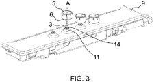
- FIG. 3 an isometric view of a section of the gas cooktop where a plurality of control knob (5) and embossed form (11) is provided, is given.
- a gas control member (2) positioned below the cooktop plate (8) (see in Fig. 4 ).
- Said gas control member (2) has a rotatable shaft (3) which passes through an opening (10) of the cooktop plate (8).
- the rotatable shaft (3) connects to the control knob (5).
- one of the control knob (5) is seperated from the rotatable shaft (3) in order to be shown a section of the cooktop plate (8) where the embossed form (11) is provided.
- the cooktop plate (8) has an embossed form (11) defined along a periphery of the opening (10) in such a way that it is providing a barrier between the opening (10) and a base (9) of the cooktop plate (8).
- the embossed form (11) has an aperture (14) on a side away from the base (9).
- the rotatable shaft (3) is provided in an accessible manner through the aperture (14).
- Said rotatable shaft (3) which is rotatable around a rotation axis (A), extends in a direction of said rotation axis (A).
- the control knob (5) has a shaft connection housing (6) extending in the direction of the rotation axis (A).
- a section view of the gas cooktop where the cooktop plate (8), the gas control member (2) and the control knob (5) are provided, is given.
- the gas control member (2) having the rotatable shaft (3) is positioned below the cooktop plate (8).
- Said rotatable shaft (3) of the gas control member (2) extends in the direction of said rotation axis (A) in a manner passing through the opening (10).
- the embossed form (11) is configured along the periphery of the opening (10).
- the embossed form (11) is in the form of an elevation with respect to the base (9) of the cooktop plate (8).
- said embossed form (11) is configured as a frusto-conical form.
- the embossed form (11) has a barrier section (12) providing a barrier between the opening (10) and the base (9) of the cooktop plate (8).
- Said embossed form (11) has an aperture (14) on a side away from the base (9).
- the rotatable shaft (3) is provided in an accessible manner through the aperture (14).
- the shaft connection housing (6) passes through the aperture (14) and connects to a free end (4) of the rotatable shaft (3) in such a way that it is rotating with the rotatable shaft (3) jointly.
- the control knob (5) has a shell (16) surrounding the rotation axis (A) whereby a knob housing (7) is provided on a side facing the embossed form (11).
- an axial movement distance (L) is provided between the control knob (5) and the base (9) for an axial movement of the control knob (5) in a direction towards the base (9), when the control knob (5) is at a position away from the base (9).
- the cooktop plate (8) is made of a metal material Said metal material can be any kind of metal which can be shaped by a deep drawing process.
- the embossed form (11) is formed in a one piece manner with the cooktop plate (8).
- the usage and functionalizing of the invention is as follows; there is not any burning operation at the related gas burner (15), when the related control knob (5) is at a first position where the control knob (5) has not rotated around the rotation axis (A).
- the control knob (5) transitions from the first position to an second position, when the control knob (5) is moved axially towards the cooktop plate (8) ve rotated around the rotation axis (A).
- the control knob (5) covers the embossed form (11) by means of the shell (16) and the knob housing (7), when the control knob () is axially moved towards the cooktop plate (8).
- the axial and rotational movements of the control knob (5) is directly transmitted to the rotatable shaft (3).
- the gas control member (2) directs an amount of gas according to the rotation level of the control knob (5) and the rotatable shaft (3), to the related gas burner (15) for feeding the burning of the cooking operation.
- the barrier section (12) prevents penetrating of the liquids from the opening (10) under the control knob (5) to inside the gas cooking device (1).
Landscapes
- Engineering & Computer Science (AREA)
- Chemical & Material Sciences (AREA)
- Combustion & Propulsion (AREA)
- Mechanical Engineering (AREA)
- General Engineering & Computer Science (AREA)
- Baking, Grill, Roasting (AREA)
- Rotary Switch, Piano Key Switch, And Lever Switch (AREA)
Description
- The present invention relates to a gas cooking device comprising a cooktop plate, at least one opening provided on the cooktop plate, a gas control member positioned below the cooktop plate, having a rotatable shaft which passes through the opening.
- The patent application numbered
WO2014016114 A2 discloses a sealing element suitable for using in cooking devices, especially counter-top cooktops, preventing the liquids spilled onto the panel from leaking through the aperture by providing leak-proofing of the apertures wherein the knobs placed onto the panel are mounted and comprising a gasket seated all around the edge of the aperture on the upper surface of the panel and produced from elastic material, and also relates to the cooking device wherein the sealing element is used. -
EP 1 046 865 A2 -
CN 203375488 U describes an embedded fuel gas cooker with a double waterproof device on a rotary knob hole. -
JP 2001182941 A -
JP 2016211815 A -
EP 0 963 957 A1 describes a method of bending the perimeter of at least one opening provided in a glass-ceramic precursor plate, said perimeter describing a closed curve without sharp angles. - The invention provides an additional improvement, an additional advantage or an alternative to the prior art.
- The purpose of the present invention is to prevent liquid leakage from opening under the control knobs to inside the gas cooking device without using any kind of sealing member.
- The invention, to achieve the abovementioned purpose, a gas cooking device comprising a cooktop plate, at least one opening provided on the cooktop plate, a gas control member positioned below the cooktop plate, having a rotatable shaft which passes through the opening. In the invention, the cooktop plate has an embossed form defined along a periphery of the opening in such a way that it is providing a barrier between the opening and the cooktop plate. A control knob of the gas cooking device has a shaft connection housing extending in the direction of a rotation axis of the rotatable shaft, wherein the shaft connection housing connects to a free end of the rotatable shaft in such a way that it is rotating with the rotatable shaft jointly, wherein the control knob has a shell surrounding the rotation axis whereby a knob housing is provided on a side facing the embossed form, and wherein the control knob covers the embossed form by means of the shell and the knob housing. Thus, penetrating of the liquid from the opening under the control knob to inside the gas cooking device, is prevented without using any kind of sealing member such as a gasket. Since, using of the sealing member under the control knob is eliminated and therefore, the possible undesirable dislocations of the sealing member is prevented, the sealing feature under the control knob is permanently provided. Moreover, the possible short circuits in the electric system inside the gas cooking device due to the liquid leakage from the opening under the control knob, is eliminated.
- Here, the gas cooking device can be a gas cooktop or a gas oven comprising a cooktop plate. Here, the gas control member can be any kind of gas tap having a rotatable shaft.
In a possible embodiment of the invention, the cooktop plate has a base whereby the embossed form is in the form of an elevation with respect to said base. Thus, penetrating of the liquids from the opening under the control knob to inside the gas cooking device, is prevented. - In a possible embodiment of the invention, the embossed form is configured as a frusto-conical form. Thus, the sealing feature under the control knob is provided without using any kind of sealing member.
- In a possible embodiment of the invention, the embossed form has an aperture on a side away from the base, the rotatable shaft is provided in an accessible manner through the aperture and a flat surface is provided along a periphery of said aperture. Thus, the shaft connection housing can pass through the aperture in order to connect to the rotatable shaft.
- Moreover, sharp edges which can be unsafe for the users, is eliminated by forming the periphery of the aperture as the flat surface.
- The control knob has a shaft connection housing extending in the direction of a rotation axis of the rotatable shaft and the shaft connection housing connects to a free end of the rotatable shaft in such a way that it is rotating with the rotatable shaft jointly. Thus, the rotational movement and/or axial movement of the control knob can be transmitted to the rotatable shaft.
- The control knob has a shell surrounding the rotation axis whereby a knob housing is provided on a side facing the embossed form. Thus, the movement of the control knob in the direction of the rotation axis is not restricted.
- In a possible embodiment of the invention, an axial movement distance is provided between the control knob and the base for an axial movement of the control knob in a direction towards the base, when the control knob is at a position away from the base. Thus, the distance for the axial movement of the control knob, is provided.
- Further advantages may become apparent from the following description of the figure(s). In the figure, an exemplary embodiment of the invention is shown. The figure, the description and the claims contain a plurality of features in combination. The person having ordinary skill in the art will purposefully also consider the features separately and will find further expedient combinations.
- If there is more than one specimen of a certain object, only one of these is given a reference numeral in the figures and in the description. The description of this specimen maybe correspondingly transferred to the other specimens of the object.
- The figures, whose brief explanations are herewith provided, are solely intended for providing a better understanding of the present invention and are as such not intended to define the scope of protection or the context in which said scope is to be interpreted in the absence of the description.
-
Fig.1 represents an isometric view of the exemplary gas cooktop. -
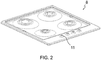
Fig. 2 represents an isometric view of the cooktop plate of the gas cooktop. -
Fig. 3 represents an isometric view of a section of the gas cooktop where a plurality of control knob and embossed form is provided. -
Fig. 4 represents a section view of the gas cooktop where the cooktop plate, the gas control member and the control knob is provided. -
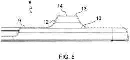
Fig. 5 represents a side view of the cooktop plate where the embossed form is provided.
As can be seen inFig. 1 , the subject matter gas cooking device (1), i.e. a gas cooktop, comprising a cooktop plate (8) having a width and depth. Said gas cooking device (1) further comprises a plurality of gas burners (15) and control knobs (5) for controlling a burning operation of the gas burners (15). In the present invention, as can be seen inFig. 2 , the cooktop plate (8) has an embossed form (11) configured under the control knob (5). - In
Fig. 3 , an isometric view of a section of the gas cooktop where a plurality of control knob (5) and embossed form (11) is provided, is given. There is a gas control member (2) positioned below the cooktop plate (8) (see inFig. 4 ). Said gas control member (2) has a rotatable shaft (3) which passes through an opening (10) of the cooktop plate (8). The rotatable shaft (3) connects to the control knob (5). InFig. 3 , one of the control knob (5) is seperated from the rotatable shaft (3) in order to be shown a section of the cooktop plate (8) where the embossed form (11) is provided. In a possible embodiment of the invention, the cooktop plate (8) has an embossed form (11) defined along a periphery of the opening (10) in such a way that it is providing a barrier between the opening (10) and a base (9) of the cooktop plate (8). The embossed form (11) has an aperture (14) on a side away from the base (9). As can be seen inFig. 3 , the rotatable shaft (3) is provided in an accessible manner through the aperture (14). Said rotatable shaft (3) which is rotatable around a rotation axis (A), extends in a direction of said rotation axis (A). Furthermore, the control knob (5) has a shaft connection housing (6) extending in the direction of the rotation axis (A). - In
Fig. 4 , a section view of the gas cooktop where the cooktop plate (8), the gas control member (2) and the control knob (5) are provided, is given. The gas control member (2) having the rotatable shaft (3) is positioned below the cooktop plate (8). Said rotatable shaft (3) of the gas control member (2) extends in the direction of said rotation axis (A) in a manner passing through the opening (10). In a possible embodiment, the embossed form (11) is configured along the periphery of the opening (10). In more details, the embossed form (11) is in the form of an elevation with respect to the base (9) of the cooktop plate (8). Preferably, said embossed form (11) is configured as a frusto-conical form. As can be seen inFig. 5 , the embossed form (11) has a barrier section (12) providing a barrier between the opening (10) and the base (9) of the cooktop plate (8). Said embossed form (11) has an aperture (14) on a side away from the base (9). The rotatable shaft (3) is provided in an accessible manner through the aperture (14). There is a flat surface (13) provided along a periphery of said aperture (14) in order to eliminate the sharp edges of the embossed form (11) which can be unsafe for the users. The shaft connection housing (6) passes through the aperture (14) and connects to a free end (4) of the rotatable shaft (3) in such a way that it is rotating with the rotatable shaft (3) jointly. The control knob (5) has a shell (16) surrounding the rotation axis (A) whereby a knob housing (7) is provided on a side facing the embossed form (11). In a possible embodiment, an axial movement distance (L) is provided between the control knob (5) and the base (9) for an axial movement of the control knob (5) in a direction towards the base (9), when the control knob (5) is at a position away from the base (9). - In a possible embodiment of the invention, the cooktop plate (8) is made of a metal material Said metal material can be any kind of metal which can be shaped by a deep drawing process. In a possible embodiment, the embossed form (11) is formed in a one piece manner with the cooktop plate (8).
- In the light of the structural details and figures of the possible embodiment given above, the usage and functionalizing of the invention is as follows; there is not any burning operation at the related gas burner (15), when the related control knob (5) is at a first position where the control knob (5) has not rotated around the rotation axis (A). The control knob (5) transitions from the first position to an second position, when the control knob (5) is moved axially towards the cooktop plate (8) ve rotated around the rotation axis (A). The control knob (5) covers the embossed form (11) by means of the shell (16) and the knob housing (7), when the control knob () is axially moved towards the cooktop plate (8). The axial and rotational movements of the control knob (5) is directly transmitted to the rotatable shaft (3). The gas control member (2) directs an amount of gas according to the rotation level of the control knob (5) and the rotatable shaft (3), to the related gas burner (15) for feeding the burning of the cooking operation. In case of an overflow onto the cooktop plate (8) during the cooking operation, the barrier section (12) prevents penetrating of the liquids from the opening (10) under the control knob (5) to inside the gas cooking device (1).
-
- 1. Gas cooking device
- 2. Gas control member
- 3. Rotatable shaft
- 4. Free end
- 5. Control knob
- 6. Shaft connection housing
- 7. Knob housing
- 8. Cooktop plate
- 9. Base
- 10. Opening
- 11. Embossed form
- 12. Barrier section
- 13. Flat surface
- 14. Aperture
- 15. Gas burner
- 16. Shell
- L. Axial movement distance
- A. Rotation axis
Claims (5)
- A gas cooking device (1) comprising a cooktop plate (8), at least one opening (10) provided on the cooktop plate (8), a gas control member (2) positioned below the cooktop plate (8), having a rotatable shaft (3) which passes through the opening (10), wherein the cooktop plate (8) has an embossed form (11) defined along a periphery of the opening (10) in such a way that it is providing a barrier between the opening (10) and the cooktop plate (8), wherein a control knob (5) of the gas cooking device (1) has a shaft connection housing (6) extending in the direction of a rotation axis (A) of the rotatable shaft (3), wherein the shaft connection housing (6) connects to a free end (4) of the rotatable shaft (3) in such a way that it is rotating with the rotatable shaft (3) jointly, wherein the control knob (5) has a shell (16) surrounding the rotation axis (A) whereby a knob housing (7) is provided on a side facing the embossed form (11), characterized in that the control knob (5) covers the embossed form (11) by means of the shell (16) and the knob housing (7).
- A gas cooking device (1) according to Claim 1, wherein the cooktop plate (8) has a base (9) whereby the embossed form (11) is in the form of an elevation with respect to said base (9).
- A gas cooking device (1) according to Claim 1 or 2, wherein the embossed form (11) is configured as a frusto-conical form.
- A gas cooking device (1) according to Claim 2 or 3, wherein the embossed form (11) has an aperture (14) on a side away from the base (9), wherein the rotatable shaft (3) is provided in an accessible manner through the aperture (14) and wherein a flat surface (13) is provided along a periphery of said aperture (14).
- A gas cooking device (1) according to any of the preceding claims, wherein an axial movement distance (L) is provided between the control knob (5) and the base (9) for an axial movement of the control knob (5) in a direction towards the base (9), when the control knob (5) is at a position away from the base (9).
Applications Claiming Priority (1)
| Application Number | Priority Date | Filing Date | Title |
|---|---|---|---|
| TR201815718 | 2018-10-22 |
Publications (2)
| Publication Number | Publication Date |
|---|---|
| EP3643971A1 EP3643971A1 (en) | 2020-04-29 |
| EP3643971B1 true EP3643971B1 (en) | 2021-06-09 |
Family
ID=68280744
Family Applications (1)
| Application Number | Title | Priority Date | Filing Date |
|---|---|---|---|
| EP19202537.7A Active EP3643971B1 (en) | 2018-10-22 | 2019-10-10 | A gas cooking device comprising a cooktop plate |
Country Status (1)
| Country | Link |
|---|---|
| EP (1) | EP3643971B1 (en) |
Families Citing this family (1)
| Publication number | Priority date | Publication date | Assignee | Title |
|---|---|---|---|---|
| EP3933272B1 (en) * | 2020-06-30 | 2023-08-30 | BSH Hausgeräte GmbH | Gas stove |
Family Cites Families (8)
| Publication number | Priority date | Publication date | Assignee | Title |
|---|---|---|---|---|
| FR2777559B1 (en) * | 1998-04-16 | 2000-07-13 | En Nom Collectif Eurokera Soc | MANUFACTURE OF VITROCERAMIC PLATES WITH OPENING (S) WITH A DEFORMED EDGE; DEFORMED VITROCERAMIC PLATES |
| EP1046865A3 (en) * | 1999-04-19 | 2003-04-23 | Curvet SPA | Tempered glass hob for kitchen |
| JP2001182941A (en) * | 1999-12-22 | 2001-07-06 | Matsushita Electric Ind Co Ltd | Gas stove protection device |
| ES2204349B1 (en) * | 2003-12-10 | 2005-07-16 | Bsh Electrodomesticos España S.A. | DEVICE FOR ADJUSTING A GAS FLAME ON A GAS KITCHEN PLATE. |
| JP5271988B2 (en) * | 2010-10-06 | 2013-08-21 | リンナイ株式会社 | Gas hob operation part waterproof structure |
| EP2877784B1 (en) | 2012-07-27 | 2017-04-05 | Arçelik Anonim Sirketi | Cooking device with a sealing element for knobs |
| CN203375488U (en) * | 2013-06-14 | 2014-01-01 | 中山百得厨卫有限公司 | Embedded fuel gas cooker with double waterproof device on rotary knob hole |
| JP6422393B2 (en) * | 2015-05-12 | 2018-11-14 | リンナイ株式会社 | Gas stove |
-
2019
- 2019-10-10 EP EP19202537.7A patent/EP3643971B1/en active Active
Also Published As
| Publication number | Publication date |
|---|---|
| EP3643971A1 (en) | 2020-04-29 |
Similar Documents
| Publication | Publication Date | Title |
|---|---|---|
| KR102458204B1 (en) | Knob assembly having display and home appliance using the same | |
| EP2097672B1 (en) | Hub and spoke burner port configuration | |
| EP2592355B1 (en) | Method of operating a cooking hob and household appliance | |
| KR102346353B1 (en) | Knob assembly for cook top | |
| WO2014016114A2 (en) | A sealing element for cooking device knobs and the cooking device wherein the sealing element is used | |
| US5357080A (en) | Cooktop with control surface on frame leg | |
| EP3023702B1 (en) | Cooking device | |
| US9476594B2 (en) | Domestic cooking appliance having a gas switch mounting system | |
| EP3643971A1 (en) | A gas cooking device comprising a cooktop plate | |
| EP3049726B1 (en) | A cooker comprising a sealing element | |
| US10082295B2 (en) | Gas heating arrangement and method for operating a gas heating arrangement | |
| US5129283A (en) | Push to turn mechanism | |
| EP2827060A1 (en) | Cam gas tap with a plug and integrated cam for domestic cooking appliances | |
| EP3933272B1 (en) | Gas stove | |
| KR102133283B1 (en) | Knob assembly for cook top | |
| EP2708816A2 (en) | A touch-sensitive gas control system and a cam gas tap for domestic cooking appliances | |
| CN105612379B (en) | Gas fittings, hobs and gas cookers | |
| KR101745618B1 (en) | Induction heater cooker | |
| JP2002089854A (en) | Built-in heater | |
| EP4036475B1 (en) | Domestic appliance | |
| WO2013098036A1 (en) | A cooking device | |
| HK1224001A1 (en) | Gas stove | |
| EP3847397B1 (en) | A gas cooker comprising a knob | |
| KR20030040015A (en) | Gas range | |
| WO2024078950A1 (en) | Operating system of a gas cooking appliance |
Legal Events
| Date | Code | Title | Description |
|---|---|---|---|
| PUAI | Public reference made under article 153(3) epc to a published international application that has entered the european phase |
Free format text: ORIGINAL CODE: 0009012 |
|
| STAA | Information on the status of an ep patent application or granted ep patent |
Free format text: STATUS: THE APPLICATION HAS BEEN PUBLISHED |
|
| AK | Designated contracting states |
Kind code of ref document: A1 Designated state(s): AL AT BE BG CH CY CZ DE DK EE ES FI FR GB GR HR HU IE IS IT LI LT LU LV MC MK MT NL NO PL PT RO RS SE SI SK SM TR |
|
| AX | Request for extension of the european patent |
Extension state: BA ME |
|
| STAA | Information on the status of an ep patent application or granted ep patent |
Free format text: STATUS: REQUEST FOR EXAMINATION WAS MADE |
|
| 17P | Request for examination filed |
Effective date: 20201029 |
|
| RBV | Designated contracting states (corrected) |
Designated state(s): AL AT BE BG CH CY CZ DE DK EE ES FI FR GB GR HR HU IE IS IT LI LT LU LV MC MK MT NL NO PL PT RO RS SE SI SK SM TR |
|
| GRAP | Despatch of communication of intention to grant a patent |
Free format text: ORIGINAL CODE: EPIDOSNIGR1 |
|
| STAA | Information on the status of an ep patent application or granted ep patent |
Free format text: STATUS: GRANT OF PATENT IS INTENDED |
|
| INTG | Intention to grant announced |
Effective date: 20210129 |
|
| GRAS | Grant fee paid |
Free format text: ORIGINAL CODE: EPIDOSNIGR3 |
|
| GRAA | (expected) grant |
Free format text: ORIGINAL CODE: 0009210 |
|
| STAA | Information on the status of an ep patent application or granted ep patent |
Free format text: STATUS: THE PATENT HAS BEEN GRANTED |
|
| AK | Designated contracting states |
Kind code of ref document: B1 Designated state(s): AL AT BE BG CH CY CZ DE DK EE ES FI FR GB GR HR HU IE IS IT LI LT LU LV MC MK MT NL NO PL PT RO RS SE SI SK SM TR |
|
| REG | Reference to a national code |
Ref country code: GB Ref legal event code: FG4D |
|
| REG | Reference to a national code |
Ref country code: CH Ref legal event code: EP Ref country code: AT Ref legal event code: REF Ref document number: 1400822 Country of ref document: AT Kind code of ref document: T Effective date: 20210615 |
|
| REG | Reference to a national code |
Ref country code: DE Ref legal event code: R096 Ref document number: 602019005232 Country of ref document: DE |
|
| REG | Reference to a national code |
Ref country code: IE Ref legal event code: FG4D |
|
| REG | Reference to a national code |
Ref country code: LT Ref legal event code: MG9D |
|
| PG25 | Lapsed in a contracting state [announced via postgrant information from national office to epo] |
Ref country code: FI Free format text: LAPSE BECAUSE OF FAILURE TO SUBMIT A TRANSLATION OF THE DESCRIPTION OR TO PAY THE FEE WITHIN THE PRESCRIBED TIME-LIMIT Effective date: 20210609 Ref country code: LT Free format text: LAPSE BECAUSE OF FAILURE TO SUBMIT A TRANSLATION OF THE DESCRIPTION OR TO PAY THE FEE WITHIN THE PRESCRIBED TIME-LIMIT Effective date: 20210609 Ref country code: HR Free format text: LAPSE BECAUSE OF FAILURE TO SUBMIT A TRANSLATION OF THE DESCRIPTION OR TO PAY THE FEE WITHIN THE PRESCRIBED TIME-LIMIT Effective date: 20210609 Ref country code: BG Free format text: LAPSE BECAUSE OF FAILURE TO SUBMIT A TRANSLATION OF THE DESCRIPTION OR TO PAY THE FEE WITHIN THE PRESCRIBED TIME-LIMIT Effective date: 20210909 |
|
| REG | Reference to a national code |
Ref country code: AT Ref legal event code: MK05 Ref document number: 1400822 Country of ref document: AT Kind code of ref document: T Effective date: 20210609 |
|
| REG | Reference to a national code |
Ref country code: NL Ref legal event code: MP Effective date: 20210609 |
|
| PG25 | Lapsed in a contracting state [announced via postgrant information from national office to epo] |
Ref country code: NO Free format text: LAPSE BECAUSE OF FAILURE TO SUBMIT A TRANSLATION OF THE DESCRIPTION OR TO PAY THE FEE WITHIN THE PRESCRIBED TIME-LIMIT Effective date: 20210909 Ref country code: LV Free format text: LAPSE BECAUSE OF FAILURE TO SUBMIT A TRANSLATION OF THE DESCRIPTION OR TO PAY THE FEE WITHIN THE PRESCRIBED TIME-LIMIT Effective date: 20210609 Ref country code: SE Free format text: LAPSE BECAUSE OF FAILURE TO SUBMIT A TRANSLATION OF THE DESCRIPTION OR TO PAY THE FEE WITHIN THE PRESCRIBED TIME-LIMIT Effective date: 20210609 Ref country code: RS Free format text: LAPSE BECAUSE OF FAILURE TO SUBMIT A TRANSLATION OF THE DESCRIPTION OR TO PAY THE FEE WITHIN THE PRESCRIBED TIME-LIMIT Effective date: 20210609 Ref country code: GR Free format text: LAPSE BECAUSE OF FAILURE TO SUBMIT A TRANSLATION OF THE DESCRIPTION OR TO PAY THE FEE WITHIN THE PRESCRIBED TIME-LIMIT Effective date: 20210910 |
|
| PG25 | Lapsed in a contracting state [announced via postgrant information from national office to epo] |
Ref country code: SK Free format text: LAPSE BECAUSE OF FAILURE TO SUBMIT A TRANSLATION OF THE DESCRIPTION OR TO PAY THE FEE WITHIN THE PRESCRIBED TIME-LIMIT Effective date: 20210609 Ref country code: EE Free format text: LAPSE BECAUSE OF FAILURE TO SUBMIT A TRANSLATION OF THE DESCRIPTION OR TO PAY THE FEE WITHIN THE PRESCRIBED TIME-LIMIT Effective date: 20210609 Ref country code: ES Free format text: LAPSE BECAUSE OF FAILURE TO SUBMIT A TRANSLATION OF THE DESCRIPTION OR TO PAY THE FEE WITHIN THE PRESCRIBED TIME-LIMIT Effective date: 20210609 Ref country code: CZ Free format text: LAPSE BECAUSE OF FAILURE TO SUBMIT A TRANSLATION OF THE DESCRIPTION OR TO PAY THE FEE WITHIN THE PRESCRIBED TIME-LIMIT Effective date: 20210609 Ref country code: AT Free format text: LAPSE BECAUSE OF FAILURE TO SUBMIT A TRANSLATION OF THE DESCRIPTION OR TO PAY THE FEE WITHIN THE PRESCRIBED TIME-LIMIT Effective date: 20210609 Ref country code: RO Free format text: LAPSE BECAUSE OF FAILURE TO SUBMIT A TRANSLATION OF THE DESCRIPTION OR TO PAY THE FEE WITHIN THE PRESCRIBED TIME-LIMIT Effective date: 20210609 Ref country code: NL Free format text: LAPSE BECAUSE OF FAILURE TO SUBMIT A TRANSLATION OF THE DESCRIPTION OR TO PAY THE FEE WITHIN THE PRESCRIBED TIME-LIMIT Effective date: 20210609 Ref country code: PT Free format text: LAPSE BECAUSE OF FAILURE TO SUBMIT A TRANSLATION OF THE DESCRIPTION OR TO PAY THE FEE WITHIN THE PRESCRIBED TIME-LIMIT Effective date: 20211011 Ref country code: SM Free format text: LAPSE BECAUSE OF FAILURE TO SUBMIT A TRANSLATION OF THE DESCRIPTION OR TO PAY THE FEE WITHIN THE PRESCRIBED TIME-LIMIT Effective date: 20210609 |
|
| PG25 | Lapsed in a contracting state [announced via postgrant information from national office to epo] |
Ref country code: PL Free format text: LAPSE BECAUSE OF FAILURE TO SUBMIT A TRANSLATION OF THE DESCRIPTION OR TO PAY THE FEE WITHIN THE PRESCRIBED TIME-LIMIT Effective date: 20210609 |
|
| REG | Reference to a national code |
Ref country code: DE Ref legal event code: R097 Ref document number: 602019005232 Country of ref document: DE |
|
| PLBE | No opposition filed within time limit |
Free format text: ORIGINAL CODE: 0009261 |
|
| STAA | Information on the status of an ep patent application or granted ep patent |
Free format text: STATUS: NO OPPOSITION FILED WITHIN TIME LIMIT |
|
| PG25 | Lapsed in a contracting state [announced via postgrant information from national office to epo] |
Ref country code: DK Free format text: LAPSE BECAUSE OF FAILURE TO SUBMIT A TRANSLATION OF THE DESCRIPTION OR TO PAY THE FEE WITHIN THE PRESCRIBED TIME-LIMIT Effective date: 20210609 |
|
| REG | Reference to a national code |
Ref country code: DE Ref legal event code: R119 Ref document number: 602019005232 Country of ref document: DE |
|
| 26N | No opposition filed |
Effective date: 20220310 |
|
| PG25 | Lapsed in a contracting state [announced via postgrant information from national office to epo] |
Ref country code: AL Free format text: LAPSE BECAUSE OF FAILURE TO SUBMIT A TRANSLATION OF THE DESCRIPTION OR TO PAY THE FEE WITHIN THE PRESCRIBED TIME-LIMIT Effective date: 20210609 |
|
| REG | Reference to a national code |
Ref country code: BE Ref legal event code: MM Effective date: 20211031 |
|
| PG25 | Lapsed in a contracting state [announced via postgrant information from national office to epo] |
Ref country code: MC Free format text: LAPSE BECAUSE OF FAILURE TO SUBMIT A TRANSLATION OF THE DESCRIPTION OR TO PAY THE FEE WITHIN THE PRESCRIBED TIME-LIMIT Effective date: 20210609 |
|
| PG25 | Lapsed in a contracting state [announced via postgrant information from national office to epo] |
Ref country code: LU Free format text: LAPSE BECAUSE OF NON-PAYMENT OF DUE FEES Effective date: 20211010 Ref country code: IT Free format text: LAPSE BECAUSE OF FAILURE TO SUBMIT A TRANSLATION OF THE DESCRIPTION OR TO PAY THE FEE WITHIN THE PRESCRIBED TIME-LIMIT Effective date: 20210609 Ref country code: BE Free format text: LAPSE BECAUSE OF NON-PAYMENT OF DUE FEES Effective date: 20211031 Ref country code: DE Free format text: LAPSE BECAUSE OF NON-PAYMENT OF DUE FEES Effective date: 20220503 |
|
| PG25 | Lapsed in a contracting state [announced via postgrant information from national office to epo] |
Ref country code: FR Free format text: LAPSE BECAUSE OF NON-PAYMENT OF DUE FEES Effective date: 20211031 |
|
| PG25 | Lapsed in a contracting state [announced via postgrant information from national office to epo] |
Ref country code: IE Free format text: LAPSE BECAUSE OF NON-PAYMENT OF DUE FEES Effective date: 20211010 |
|
| REG | Reference to a national code |
Ref country code: CH Ref legal event code: PL |
|
| PG25 | Lapsed in a contracting state [announced via postgrant information from national office to epo] |
Ref country code: CY Free format text: LAPSE BECAUSE OF FAILURE TO SUBMIT A TRANSLATION OF THE DESCRIPTION OR TO PAY THE FEE WITHIN THE PRESCRIBED TIME-LIMIT Effective date: 20210609 |
|
| PG25 | Lapsed in a contracting state [announced via postgrant information from national office to epo] |
Ref country code: LI Free format text: LAPSE BECAUSE OF NON-PAYMENT OF DUE FEES Effective date: 20221031 Ref country code: HU Free format text: LAPSE BECAUSE OF FAILURE TO SUBMIT A TRANSLATION OF THE DESCRIPTION OR TO PAY THE FEE WITHIN THE PRESCRIBED TIME-LIMIT; INVALID AB INITIO Effective date: 20191010 Ref country code: CH Free format text: LAPSE BECAUSE OF NON-PAYMENT OF DUE FEES Effective date: 20221031 |
|
| PG25 | Lapsed in a contracting state [announced via postgrant information from national office to epo] |
Ref country code: MK Free format text: LAPSE BECAUSE OF FAILURE TO SUBMIT A TRANSLATION OF THE DESCRIPTION OR TO PAY THE FEE WITHIN THE PRESCRIBED TIME-LIMIT Effective date: 20210609 |
|
| PG25 | Lapsed in a contracting state [announced via postgrant information from national office to epo] |
Ref country code: MT Free format text: LAPSE BECAUSE OF FAILURE TO SUBMIT A TRANSLATION OF THE DESCRIPTION OR TO PAY THE FEE WITHIN THE PRESCRIBED TIME-LIMIT Effective date: 20210609 |
|
| PGFP | Annual fee paid to national office [announced via postgrant information from national office to epo] |
Ref country code: GB Payment date: 20251024 Year of fee payment: 7 |
|
| PGFP | Annual fee paid to national office [announced via postgrant information from national office to epo] |
Ref country code: TR Payment date: 20251002 Year of fee payment: 7 |