EP3643943A1 - Non-excitation operable electromagnetic brake - Google Patents
Non-excitation operable electromagnetic brake Download PDFInfo
- Publication number
- EP3643943A1 EP3643943A1 EP19179518.6A EP19179518A EP3643943A1 EP 3643943 A1 EP3643943 A1 EP 3643943A1 EP 19179518 A EP19179518 A EP 19179518A EP 3643943 A1 EP3643943 A1 EP 3643943A1
- Authority
- EP
- European Patent Office
- Prior art keywords
- releasing
- rotary cam
- state
- brake
- acting
- Prior art date
- Legal status (The legal status is an assumption and is not a legal conclusion. Google has not performed a legal analysis and makes no representation as to the accuracy of the status listed.)
- Granted
Links
Images


Classifications
-
- F—MECHANICAL ENGINEERING; LIGHTING; HEATING; WEAPONS; BLASTING
- F16—ENGINEERING ELEMENTS AND UNITS; GENERAL MEASURES FOR PRODUCING AND MAINTAINING EFFECTIVE FUNCTIONING OF MACHINES OR INSTALLATIONS; THERMAL INSULATION IN GENERAL
- F16D—COUPLINGS FOR TRANSMITTING ROTATION; CLUTCHES; BRAKES
- F16D65/00—Parts or details
- F16D65/14—Actuating mechanisms for brakes; Means for initiating operation at a predetermined position
- F16D65/16—Actuating mechanisms for brakes; Means for initiating operation at a predetermined position arranged in or on the brake
- F16D65/18—Actuating mechanisms for brakes; Means for initiating operation at a predetermined position arranged in or on the brake adapted for drawing members together, e.g. for disc brakes
-
- B—PERFORMING OPERATIONS; TRANSPORTING
- B60—VEHICLES IN GENERAL
- B60T—VEHICLE BRAKE CONTROL SYSTEMS OR PARTS THEREOF; BRAKE CONTROL SYSTEMS OR PARTS THEREOF, IN GENERAL; ARRANGEMENT OF BRAKING ELEMENTS ON VEHICLES IN GENERAL; PORTABLE DEVICES FOR PREVENTING UNWANTED MOVEMENT OF VEHICLES; VEHICLE MODIFICATIONS TO FACILITATE COOLING OF BRAKES
- B60T13/00—Transmitting braking action from initiating means to ultimate brake actuator with power assistance or drive; Brake systems incorporating such transmitting means, e.g. air-pressure brake systems
- B60T13/10—Transmitting braking action from initiating means to ultimate brake actuator with power assistance or drive; Brake systems incorporating such transmitting means, e.g. air-pressure brake systems with fluid assistance, drive, or release
- B60T13/58—Combined or convertible systems
-
- B—PERFORMING OPERATIONS; TRANSPORTING
- B60—VEHICLES IN GENERAL
- B60T—VEHICLE BRAKE CONTROL SYSTEMS OR PARTS THEREOF; BRAKE CONTROL SYSTEMS OR PARTS THEREOF, IN GENERAL; ARRANGEMENT OF BRAKING ELEMENTS ON VEHICLES IN GENERAL; PORTABLE DEVICES FOR PREVENTING UNWANTED MOVEMENT OF VEHICLES; VEHICLE MODIFICATIONS TO FACILITATE COOLING OF BRAKES
- B60T13/00—Transmitting braking action from initiating means to ultimate brake actuator with power assistance or drive; Brake systems incorporating such transmitting means, e.g. air-pressure brake systems
- B60T13/74—Transmitting braking action from initiating means to ultimate brake actuator with power assistance or drive; Brake systems incorporating such transmitting means, e.g. air-pressure brake systems with electrical assistance or drive
- B60T13/748—Transmitting braking action from initiating means to ultimate brake actuator with power assistance or drive; Brake systems incorporating such transmitting means, e.g. air-pressure brake systems with electrical assistance or drive acting on electro-magnetic brakes
-
- B—PERFORMING OPERATIONS; TRANSPORTING
- B60—VEHICLES IN GENERAL
- B60T—VEHICLE BRAKE CONTROL SYSTEMS OR PARTS THEREOF; BRAKE CONTROL SYSTEMS OR PARTS THEREOF, IN GENERAL; ARRANGEMENT OF BRAKING ELEMENTS ON VEHICLES IN GENERAL; PORTABLE DEVICES FOR PREVENTING UNWANTED MOVEMENT OF VEHICLES; VEHICLE MODIFICATIONS TO FACILITATE COOLING OF BRAKES
- B60T7/00—Brake-action initiating means
- B60T7/02—Brake-action initiating means for personal initiation
- B60T7/08—Brake-action initiating means for personal initiation hand actuated
-
- F—MECHANICAL ENGINEERING; LIGHTING; HEATING; WEAPONS; BLASTING
- F16—ENGINEERING ELEMENTS AND UNITS; GENERAL MEASURES FOR PRODUCING AND MAINTAINING EFFECTIVE FUNCTIONING OF MACHINES OR INSTALLATIONS; THERMAL INSULATION IN GENERAL
- F16D—COUPLINGS FOR TRANSMITTING ROTATION; CLUTCHES; BRAKES
- F16D55/00—Brakes with substantially-radial braking surfaces pressed together in axial direction, e.g. disc brakes
- F16D55/02—Brakes with substantially-radial braking surfaces pressed together in axial direction, e.g. disc brakes with axially-movable discs or pads pressed against axially-located rotating members
-
- F—MECHANICAL ENGINEERING; LIGHTING; HEATING; WEAPONS; BLASTING
- F16—ENGINEERING ELEMENTS AND UNITS; GENERAL MEASURES FOR PRODUCING AND MAINTAINING EFFECTIVE FUNCTIONING OF MACHINES OR INSTALLATIONS; THERMAL INSULATION IN GENERAL
- F16D—COUPLINGS FOR TRANSMITTING ROTATION; CLUTCHES; BRAKES
- F16D59/00—Self-acting brakes, e.g. coming into operation at a predetermined speed
- F16D59/02—Self-acting brakes, e.g. coming into operation at a predetermined speed spring-loaded and adapted to be released by mechanical, fluid, or electromagnetic means
-
- F—MECHANICAL ENGINEERING; LIGHTING; HEATING; WEAPONS; BLASTING
- F16—ENGINEERING ELEMENTS AND UNITS; GENERAL MEASURES FOR PRODUCING AND MAINTAINING EFFECTIVE FUNCTIONING OF MACHINES OR INSTALLATIONS; THERMAL INSULATION IN GENERAL
- F16H—GEARING
- F16H25/00—Gearings comprising primarily only cams, cam-followers and screw-and-nut mechanisms
- F16H25/18—Gearings comprising primarily only cams, cam-followers and screw-and-nut mechanisms for conveying or interconverting oscillating or reciprocating motions
- F16H25/20—Screw mechanisms
- F16H25/24—Elements essential to such mechanisms, e.g. screws, nuts
- F16H25/2454—Brakes; Rotational locks
-
- F—MECHANICAL ENGINEERING; LIGHTING; HEATING; WEAPONS; BLASTING
- F16—ENGINEERING ELEMENTS AND UNITS; GENERAL MEASURES FOR PRODUCING AND MAINTAINING EFFECTIVE FUNCTIONING OF MACHINES OR INSTALLATIONS; THERMAL INSULATION IN GENERAL
- F16H—GEARING
- F16H3/00—Toothed gearings for conveying rotary motion with variable gear ratio or for reversing rotary motion
- F16H3/44—Toothed gearings for conveying rotary motion with variable gear ratio or for reversing rotary motion using gears having orbital motion
- F16H3/72—Toothed gearings for conveying rotary motion with variable gear ratio or for reversing rotary motion using gears having orbital motion with a secondary drive, e.g. regulating motor, in order to vary speed continuously
- F16H3/721—Toothed gearings for conveying rotary motion with variable gear ratio or for reversing rotary motion using gears having orbital motion with a secondary drive, e.g. regulating motor, in order to vary speed continuously the secondary drive being an energy dissipating device, e.g. regulating brake, in order to vary speed continuously
-
- F—MECHANICAL ENGINEERING; LIGHTING; HEATING; WEAPONS; BLASTING
- F16—ENGINEERING ELEMENTS AND UNITS; GENERAL MEASURES FOR PRODUCING AND MAINTAINING EFFECTIVE FUNCTIONING OF MACHINES OR INSTALLATIONS; THERMAL INSULATION IN GENERAL
- F16D—COUPLINGS FOR TRANSMITTING ROTATION; CLUTCHES; BRAKES
- F16D2121/00—Type of actuator operation force
- F16D2121/18—Electric or magnetic
- F16D2121/20—Electric or magnetic using electromagnets
- F16D2121/22—Electric or magnetic using electromagnets for releasing a normally applied brake
-
- F—MECHANICAL ENGINEERING; LIGHTING; HEATING; WEAPONS; BLASTING
- F16—ENGINEERING ELEMENTS AND UNITS; GENERAL MEASURES FOR PRODUCING AND MAINTAINING EFFECTIVE FUNCTIONING OF MACHINES OR INSTALLATIONS; THERMAL INSULATION IN GENERAL
- F16D—COUPLINGS FOR TRANSMITTING ROTATION; CLUTCHES; BRAKES
- F16D2125/00—Components of actuators
- F16D2125/18—Mechanical mechanisms
- F16D2125/20—Mechanical mechanisms converting rotation to linear movement or vice versa
- F16D2125/22—Mechanical mechanisms converting rotation to linear movement or vice versa acting transversely to the axis of rotation
- F16D2125/28—Cams; Levers with cams
-
- F—MECHANICAL ENGINEERING; LIGHTING; HEATING; WEAPONS; BLASTING
- F16—ENGINEERING ELEMENTS AND UNITS; GENERAL MEASURES FOR PRODUCING AND MAINTAINING EFFECTIVE FUNCTIONING OF MACHINES OR INSTALLATIONS; THERMAL INSULATION IN GENERAL
- F16D—COUPLINGS FOR TRANSMITTING ROTATION; CLUTCHES; BRAKES
- F16D2127/00—Auxiliary mechanisms
- F16D2127/02—Release mechanisms
- F16D2127/04—Release mechanisms for manual operation
-
- F—MECHANICAL ENGINEERING; LIGHTING; HEATING; WEAPONS; BLASTING
- F16—ENGINEERING ELEMENTS AND UNITS; GENERAL MEASURES FOR PRODUCING AND MAINTAINING EFFECTIVE FUNCTIONING OF MACHINES OR INSTALLATIONS; THERMAL INSULATION IN GENERAL
- F16D—COUPLINGS FOR TRANSMITTING ROTATION; CLUTCHES; BRAKES
- F16D2129/00—Type of operation source for auxiliary mechanisms
- F16D2129/06—Electric or magnetic
- F16D2129/08—Electromagnets
Definitions
- This invention relates to a non-excitation operable electromagnetic brake.
- Non-excitation operable electromagnetic brakes include, e.g. as disclosed in Patent Document 1, one configured such that a manually operable rotary cam is provided for operating a rotor into a brake releasing state under a non-excited state of an electromagnet, thus allowing a brake releasing by a manual operation even when the electromagnet is under non-exited state.
- Patent Document 1 Japanese Unexamined Patent Application Publication No. 2002-54664
- a rotary cam is configured to press a rotor into a brake releasing state via a circumferential cam having a circumferential shape
- a change occurring in the operation reaction force applied to the rotary cam takes place in a gradual manner. This makes it difficult to judge, via the operational reaction force, whether the brake has been released or not.
- the rotary cam is set to its acting position to keep the brake released, if an external force due to e.g. vibration is applied thereto, the rotary cam can easily slip off the acting position.
- the present invention provides a non-excitation operable electromagnetic brake that includes a manually operable rotary cam for switching over a brake to a released state, but that allows easy recognition of switchover to the brake released state via an operation reaction force and that also allows reliable keeping of the rotary cam under its acting state.
- the rotor is switched from the braking state to the brake releasing state, by an action provided by the linear acting portion in the circumferential cam of the rotary cam.
- the switchover of the rotor from the braking state to the brake releasing state is provided by an action of an arcuate acting portion of the circumferential cam, the switchover of the rotor from the braking state to the brake releasing state provides larger/sharper (i.e. more distinct) change in the operation reaction force applied to the rotary cam, thus making it easy to recognize (or feel) whether the brake has been released or not, via the operation reaction force.
- a rotation restriction portion configured to restrict rotation of the rotary cam from the releasing position in a rotational direction opposite to a set rotational direction which is set for switching the rotary cam from the releasing position to the acting position.
- the rotary cam can be rotated only in the set rotational direction. So, the arrangement requires only a space just enough to allow only the rotation of the rotary cam in the set rotational direction, thus the arrangement can be formed compact.
- the rotation restriction portion is configured to come into contact with the rotary cam.
- the rotation restriction portion can be provided in a compact manner within a brake case.
- a positioning mechanism capable of switchover between a positioning state for fixedly positioning an operational tool for rotating the rotary cam to operational positions corresponding respectively to the releasing position and the acting position and a position releasing state for allowing an operation of the operational tool.
- the rotary cam can be maintained in a reliable manner at the acting position and the releasing position, respectively.
- the rotary cam can be maintained in a reliable manner at the acting position or the releasing position, without being displaced therefrom.
- the positioning mechanism further includes an urging portion for urging to maintain the positioned state, switchover from the positioning state to the position releasing state being made against an urging force of the urging portion.
- a direction of an arrow F shown in Fig. 1 represents the "vehicle body front side”
- a direction of an arrow B represents the “vehicle body rear side”
- a direction of an arrow U represents the “vehicle body upper side”
- a direction of an arrow D represents the “vehicle body lower side”
- the direction of the near side in the illustration represents the “vehicle body left side”
- the direction on the far (back) side in the illustration represents the “vehicle body right side”
- a riding type lawnmower includes a riding type vehicle body mounting a pair of left and right front wheels 1 that are pivotally steerable and a pair of left and right rear wheels 2 that can be driven, and forming a driving section 5 having a driver's seat 3, and a steering wheel 4 for steering the front wheels 1.
- a mowing device 7 is provided for mowing grass and lawn.
- a utility (implement) electric motor 8 is provided for driving the mowing device 7.
- a battery 9 for feeding electric power to the traveling electric motor 6 and the utility electric motor 8.
- a grass collecting container 10 for collecting and storing grass or lawn clippings obtained by the mowing device 7.
- a conveying duct 11 is provided for conveying the grass or lawn clippings obtained by the mowing device 7 to the grass collecting container 10.
- the conveying duct 11 is disposed to extend through between the left rear wheel 2 and the right rear wheel 2 beneath the vehicle body.
- a traveling transmission 12 for speed-changing power of the traveling motor 6 and then the resultant speed-changed power to the left and right rear wheels 2.
- a non-excitation operable electromagnetic brake 20 to be referred to simply as “electromagnetic brake 20” hereinafter configured to apply braking to the traveling motor 6 (see Fig. 1 ) and braking to the rear wheels 2 via the traveling transmission 12.
- an output shaft 6a of the traveling motor 6 and an input shaft 12a of the traveling transmission 12 are disposed coaxially side by side in the front/rear direction and operably coupled to each other via a coupling member 14.
- the input shaft 12a is rotatably supported via a bearing 15 to an input gear case 13a provided at a front portion of the transmission case 13.
- a front portion of the coupling member 14 is engaged to a splined portion of the output shaft 6a and a rear portion of the coupling member 14 is engaged to a splined portion of the input shaft 12a.
- the coupling member 14 is non-rotatably coupled with the output shaft 6a and the input shaft 12a respectively and also slidably coupled with the output shaft 6a and the input shaft 12a respectively.
- the electromagnetic brake 20, as shown in Fig. 2 includes a brake case 21 connected to a front portion of an input gear case 13a.
- the brake case 21 is formed integral with the input gear case 13a.
- the electromagnet 22 having a through hole 22a through which the output shaft 6a is inserted is fixed to the brake case 21. At a plurality of portions around the through hole 22a of the electromagnet 22, coils 26 are provided. At a plurality of portions around the through hole 22a of the electromagnet 22, springs 27 are also provided.
- the armature 23 having a through hole 23a through which the coupling member 14 is inserted, is disposed between the electromagnet 22 and the rotor 24.
- the armature 23 is supported to a support portion 21b of the brake case 21, with the armature 23 being slidable along an axial direction of the output shaft 6a.
- the rotor 24, as being non-rotatably coupled with the coupling member 14, is disposed between the armature 23 and the stator member 25.
- the rotor 24 and the coupling member 14 are coupled to each other via welding.
- the rotor 24 is supported via the coupling member 14 to the output shaft 6a and the input shaft 12a, respectively.
- the rotor 24 is rotatable together with the output shaft 6a and the input shaft 12a, respectively and also is slidable together with the coupling member 14 relative to the output shaft 6a and the input shaft 12a, respectively.
- the stator member 25 is non-rotatably supported to the support portion 21b of the brake case 21.
- the electromagnetic brake 20 is rendered into a braking state (engaged stage) for applying a braking force to the traveling motor 6 and the traveling transmission 12, in response to an operation of the electromagnet 22 to a non-excited state.
- the armature 23 will be slidably operated toward the stator member 25 by the respective springs 27, whereby the rotor 24 is pressed against the lateral portion of the stator member 25 by the armature 23, thus applying a braking force to the rotor 24 from the stator member 25.
- the rotor 24 is operated into the braking state by the respective springs 27 and the rotor 24 applies braking forces to the output shaft 6a and the input shaft 12a.
- the brake 20 when this electromagnet 22 is operated to the excited state, the brake 20 is rendered into the brake releasing state (disengaged state) for releasing application of the braking forces to the traveling motor 6 and to the traveling transmission 12.
- the armature 23 is drawn toward this electromagnet 22 against urging forces of the respective springs 27, thus releasing pressing of the rotor 24 to the stator member 25, whereby application of the braking force by the stator member 25 to the rotor 24 is released.
- the rotor 24 will be operated by the electromagnet 22 to the brake releasing state against the respective springs 27, whereby application of the braking forces by the rotor 24 to the output shaft 6a and the input shaft 12a will be released.
- the electromagnetic brake 20 is provided with a releasing mechanism 30 having a rotary cam 31 mounted within the brake case 21.
- the electromagnetic brake 20 under its braking state can be switched over to a brake releasing state by the releasing mechanism 30.
- the releasing mechanism 30, as shown in Fig. 2 includes the rotary cam 31 and a releasing plate 32 which are provided within the brake case 21 and includes also an operational tool 33 which is provided outside the brake case 21.
- the releasing plate 32 is disposed on the side opposite to the side of the rotor 24, relative to the stator member 25.
- a boss portion 32a provided at the base of the releasing plate 32 is rotatably engaged on the coupling member 14.
- the releasing plate 32 is supported to the coupling member 14 via the boss portion 32a.
- a pressing operational portion 32b engageable with the end portion of the coupling member 14 opposite to the side of the electromagnet for pressing the coupling member 14.
- a rotation stopping portion 32c protrudes in a protruding direction opposite to the protruding direction of the releasing plate 32. This rotation stopping portion 32c is retained to a stopper member 34.
- the releasing plate 32 When the releasing plate 32 is pressed toward the stator member 25, the releasing plate 32 will press the coupling member 14 with the pressing operational portion 32b and will slide relative to the output shaft 6a and the input shaft 12a simultaneously, thus allowing sliding operations by the coupling member 14 of the rotor 24 and the armature 23 toward the electromagnet 22.
- the rotary cam 31 is provided on the side opposite to the side of the stator member 25, relative to the releasing plate 32. As shown in Fig. 5 , to the rotational center of the rotary cam 31, one terminal end of an operational shaft 35 is non-rotatably connected.
- the rotary cam 31, as shown in Fig. 2 is rotatably supported via the operational shaft 35 to the boss portion 21a of the brake case 21.
- the operational shaft 35 extends in the direction intersecting the axis of the output shaft 6a.
- the operational tool 33 is provided non-rotatably, in the operational tool 35, at a portion thereof located outside the brake case 21.
- the operational tool 33 is supported to the brake case 21 to be pivotally operable with the axis P of the operational shaft 35 acting as the pivot.
- the operational tool 33 is pivotally operated, the operational shaft 35 is rotated and the rotary cam 31 is rotatably operated by the operational tool 35 about the axis P of the operational shaft 35 acting as the pivot.
- the operational tool 33 is constituted of a pivot lever.
- a rotary operational type operational tool such as a wheel.
- the operational tool 33 is configured to be pivotally operated by a manual operation to/between a releasing operational position X shown in Fig. 4 and a braking operational position Y shown in Fig. 3 .
- a pivotal range between the releasing operational position X and the braking operational position Y of the operational tool 33 is set to a pivotal range of 90 degrees.
- This pivotal range between the releasing operational position X and the braking operational position Y of the operational tool 33 may be set also to a pivotal range less than 90 degrees or a pivotal range exceeding 90 degrees.
- the rotary cam 31 When the operational tool 33 is operated to the braking operational position Y, the rotary cam 31 is rotated to a releasing position (b) as shown in Fig. 3 , thus allowing an operation by the springs 27 of operating the electromagnetic brake 20 to a braking state and also allowing an operation by the electromagnet 22 of operating the electromagnetic brake 20 to a brake releasing state.
- the operational tool 33 When the operational tool 33 is operated to the releasing operational position X, the rotary cam 31 is rotated to an acting position (a) as shown in Fig. 4 , whereby the rotary cam 31 operates the electromagnetic brake 20 to the brake releasing state against the springs 27.
- the rotary cam 31 includes a circumferential cam 38 configured to act on the rotor 24 by operating the releasing plate 32 in correspondence with a lateral face of the releasing plate 32.
- a circumferential cam 38 configured to act on the rotor 24 by operating the releasing plate 32 in correspondence with a lateral face of the releasing plate 32.
- the releasing portion 38b when the releasing portion 38b comes into correspondence with the lateral face of the releasing plate 32, due to setting of a distance from the axis P as the rotational center of the rotary cam 31 to the releasing position 38b, the releasing portion 38b releases the pressing action on the releasing plate 32, thus allowing the rotor 24 to be pressed against the stator member 25 by the respective springs 27, and also the releasing portion 38b allows the rotor 24 to be operated into the brake releasing state by the electromagnet 22.
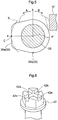
- the acting portion 38a presses the releasing plate 32 toward the electromagnet 22 against the respective springs 27 and slidably operates the rotor 24 via the coupling member 14 toward the electromagnet 22, thus operating the rotor 24 into the brake releasing state against the springs 27.
- the acting portion 38a is formed linear as shown in Fig. 5 .
- the linear shape of the acting portion 38a is a linear shape along a tangent at the center C of the acting portion 38a with respect to the rotational direction of the rotary cam.
- the tangent of the acting portion 38a at the center C in the rotational direction of the rotary cam is a tangent which is tangential to a circle S extending through the center C in the rotary cam rotational direction of the acting portion 38a centering about the axis P as the rotation center of the rotary cam 31, at an intersection point between this circle S and the center C.
- a set rotational direction A denoted with an arrow in Fig. 5 is set.
- a rotation restriction portion 37 configured to restrict rotation of the rotary cam 31. If an attempt is made to rotate the rotary cam 31 from the releasing position (b) in a rotational direction R opposite to the set rotational direction A (see Fig.
- the rotary cam 31 is rotated to the acting position (a), so that the acting portion 38a comes into contact with the releasing plate 32.
- the rotary cam 31 can effectively resist displacement from the acting position (a) even if an external force due to e.g. vibration is applied thereto.
- the releasing plate 32 Upon establishment of the contact between the acting portion 38a and the releasing plate 32, the releasing plate 32 will be pushed toward the electromagnet 22 by the acting portion 38a of the rotary cam 31 and the coupling member 14 will be pushed toward the electromagnet 22 by the pressing operational portion 32b of the boss portion 32a, whereby the pressing of the rotor 24 to the stator member 25 by the respective springs 27 will be released. Namely, the rotor 24 will be operated to the brake releasing state against the respective springs 27 by the acting portion 38a of the rotary cam 31.
- the electromagnetic brake 20 can be switched over to the brake releasing state by application to the center of the operational tool 33 of an operational force which is 1/5 of the operational force needed to be applied to the releasing plate 32 in order to operate the electromagnetic brake 20 to the brake releasing state.
- the rotary cam 31 is rotated to the releasing position (b) to bring the releasing portion 38b into correspondence with the releasing plate 32.
- the armature 23 is pressed toward the stator member 25 by the respective springs 27, the rotor 24 will be pressed against the stator member 25 by the armature 23.
- the above makes it possible for the rotor 24 to be operated to the braking state by the springs 27 and also makes it possible for the rotor 24 to be operated to the brake releasing state by the excited electromagnet 22.
- the operational tool 33 when operated to the braking operational position Y or the releasing operational position X, is positioned, i.e. fixed in position, at such respective operational position by a positioning mechanism 40.
- the positioning mechanism 40 includes an engaging portion 41 protruding downwards from the base portion of the operational tool 33, a positioning portion 42 provided in the outer circumference of the brake case 21 at a portion thereof opposed to the base portion of the operational tool 33, and a spring 43 fitted on the operational shaft 35.
- the spring 43 is disposed between a spring receiving portion 35a formed in the operational shaft 35 and the boss portion 21a of the brake case 21.
- the operational shaft 35 is slidably supported to the boss portion 21a and slidably urged toward the inner side of the brake case 21 by the spring 43.
- the positioning portion 42 as shown in Fig. 6 , there are formed first receded portions 42a for positioning the operational tool 33 at the releasing operational position X and second receded portion 42b for positioning the operational tool 33 at the braking operational position Y.
- the positioning mechanism 40 when the operational tool 33 is slid toward the positioning portion 42 in response to a sliding operation of the operational shaft 35 by the spring 43 thus engaging the engaging portion 41 within the first receded portions 42a, the base portion of the operational tool 33 is retained to the positioning portion 42, thus fixedly positioning the operational tool 33 by the positioning portion 42 at the releasing operational position X. This is a first acting state.
- the positioning mechanism 40 when the operational tool 33 is slid toward the positioning portion 42 in response to a sliding operation of the operational shaft 35 by the spring 43 thus engaging the engaging portion 41 within the second receded portions 42b, the base portion of the operational tool 33 is retained to the positioning portion 42, thus fixedly positioning the operational tool 33 by the positioning portion 42 at the braking operational position Y. This is a second acting state.
- the positioning mechanism 40 when the operational tool 33 is slid toward the outer side of the brake case 21 against the spring 43 thereby to withdraw the engaging portion 41 from the first receded portions 42a and the second receded portions 42b, the retention of the base portion of the operational tool 33 by the positioning portion 42 is released, thus allowing a pivotal movement of the operational tool 33. This is a releasing state.
- the operational tool 33 will be set to the braking operational position Y.
- the rotary cam 31 is operated to the releasing position (b) by the operational shaft 35.
- the positioning mechanism 40 is set to the second acting state with engagement of the engaging portion 41 in the second receded portions 42b and the operational tool 33 is fixedly positioned at the braking operational position Y by the positioning mechanism 40, thus maintaining the rotary cam 31 at the releasing position (b).
- displacement of the operational tool 33 due to an external force, e.g. vibration, from the braking operational position Y is prevented by the positioning mechanism 40 and displacement of the rotary cam 31 from the releasing position (b) is prevented.
- the rotary cam 31 When the rotary cam 31 is set at the releasing position (b), if the electromagnet 22 is operated into the non-excited state, the rotor 24 will be operated into the braking state by the springs 27, thus rendering the electromagnetic brake 20 into the braking state, thereby applying braking to the traveling motor 6 and the rear wheels 2.
- the electromagnet 22 When the electromagnet 22 is operated into the excited state, the rotor 24 will be operated into the brake releasing state by the electromagnet 22 against the springs 27, whereby the electromagnetic brake 20 is rendered into the brake releasing state, thus releasing braking of the traveling motor 6 and the rear wheels 2.
- the braking can be manually released by following operations.
- the operational tool 33 located at the braking operational position Y is slidably operated toward the outer side of the brake case 21 against the spring 43, thus removing the engaging portion 41 from the second receded portions 42b. With removal of the engaging portion 41 from the second receded portions 42b, the positioning mechanism 40 is rendered into the releasing state. Then, the operational tool 33 will be pivotally operated from the braking operational position Y in a pivotal direction A1 denoted with the arrow in Fig. 4 into the releasing operational position X. In the instant embodiment, by pivotally operating the operational tool 33 from the braking operational position Y in the pivotal direction A1 by a pivotal stroke of 90 degrees, the operational tool 33 is set to the releasing operational position X.
- the rotary cam 31 After the operational tool 33 is set to the releasing operational position X, the rotary cam 31 will be rotatably operated in the set rotational direction A from the releasing position (b) to the acting position (a).
- the rotary cam 31 When the rotary cam 31 is set to the acting position (a), the linear acting portion 38a of the rotary cam 31 presses the releasing plate 32, and a change occurring in the operation reaction force before/after establishment of the acting state of the acting portion 38a will be transmitted to the operational tool 33, so that the arrival of the rotary cam 31 at the acting position (a) can be confirmed through the above change in the operation reaction force.
- the rotor 24 With arrival of the rotary cam 31 at the acting position (a), the rotor 24 will be slidably operated toward the electromagnet 22 via the releasing plate 32 by the acting portion 38a of the rotary cam 31; namely, the rotor 24 will be operated to the brake releasing state by the rotary cam 31 against the springs 27, whereby the electromagnetic brake 20 will be rendered into the brake releasing state, thus releasing braking of the traveling motor 6 and the rear wheels 2.
- the present invention is applicable to a non-excitation operable electromagnetic brake to be mounted not only on the riding lawnmower, but also on various kinds of work vehicles or machines such as a tractor, a transporter vehicle, etc.
- the invention is applicable also to a non-excitation operable electromagnetic brake configured to act on various kinds of rotary bodies other than an electric motor.
Landscapes
- Engineering & Computer Science (AREA)
- General Engineering & Computer Science (AREA)
- Mechanical Engineering (AREA)
- Transportation (AREA)
- Physics & Mathematics (AREA)
- Electromagnetism (AREA)
- Braking Arrangements (AREA)
- Transmission Devices (AREA)
Abstract
Description
- This invention relates to a non-excitation operable electromagnetic brake.
- Known non-excitation operable electromagnetic brakes include, e.g. as disclosed in
Patent Document 1, one configured such that a manually operable rotary cam is provided for operating a rotor into a brake releasing state under a non-excited state of an electromagnet, thus allowing a brake releasing by a manual operation even when the electromagnet is under non-exited state. - [Patent Document 1] Japanese Unexamined Patent Application Publication No.
2002-54664 - In case a rotary cam is configured to press a rotor into a brake releasing state via a circumferential cam having a circumferential shape, when the rotor is switched from a braking state to the brake releasing state, a change occurring in the operation reaction force applied to the rotary cam takes place in a gradual manner. This makes it difficult to judge, via the operational reaction force, whether the brake has been released or not. Also, when the rotary cam is set to its acting position to keep the brake released, if an external force due to e.g. vibration is applied thereto, the rotary cam can easily slip off the acting position.
- The present invention provides a non-excitation operable electromagnetic brake that includes a manually operable rotary cam for switching over a brake to a released state, but that allows easy recognition of switchover to the brake released state via an operation reaction force and that also allows reliable keeping of the rotary cam under its acting state.
- A non-excitation operable electromagnetic brake according to the present invention comprises:
- a spring for operating a rotor into a braking state;
- an electromagnet configured, under an excited state thereof, to operate the rotor into a brake releasing state against the spring; and
- a rotary cam manually and rotationally operable between an acting position for slidably operating the rotor into the brake releasing state against the spring under the non-excited state of the electromagnet and a releasing position for releasing a slidable operation of the rotor, thus allowing an operation of the rotor into the brake releasing state by the electromagnet;
- wherein in a circumferential cam of the rotary cam, an acting portion thereof corresponding to the acting position is formed linear along a tangent at a center of the acting portion with respect to a rotary cam rotational direction.
- With the above-described arrangement, the rotor is switched from the braking state to the brake releasing state, by an action provided by the linear acting portion in the circumferential cam of the rotary cam. Thus, as compared with an arrangement that switchover of the rotor from the braking state to the brake releasing state is provided by an action of an arcuate acting portion of the circumferential cam, the switchover of the rotor from the braking state to the brake releasing state provides larger/sharper (i.e. more distinct) change in the operation reaction force applied to the rotary cam, thus making it easy to recognize (or feel) whether the brake has been released or not, via the operation reaction force.
- Further, when the acting portion of the circumferential cam of the rotary cam comes into contact with an action target, this contact takes place in the form of a line contact due to the linear shape of the acting portion. Therefore, even if an external force such as vibration is applied, slipping displacement of the rotary cam off the acting position will hardly occur, so that the brake which has been set to the brake releasing state can be maintained in a reliable manner at this position without being easily and inadvertently switched over to the braking state due to vibration, etc.
- In the present invention, preferably, there is provided a rotation restriction portion configured to restrict rotation of the rotary cam from the releasing position in a rotational direction opposite to a set rotational direction which is set for switching the rotary cam from the releasing position to the acting position.
- With the above-described arrangement, the rotary cam can be rotated only in the set rotational direction. So, the arrangement requires only a space just enough to allow only the rotation of the rotary cam in the set rotational direction, thus the arrangement can be formed compact.
- In the present invention, preferably, the rotation restriction portion is configured to come into contact with the rotary cam.
- With the above-described arrangement, the rotation restriction portion can be provided in a compact manner within a brake case.
- In the present invention, preferably, there is provided a positioning mechanism capable of switchover between a positioning state for fixedly positioning an operational tool for rotating the rotary cam to operational positions corresponding respectively to the releasing position and the acting position and a position releasing state for allowing an operation of the operational tool.
- With the above-described arrangement, by positioning of the operational tool by the positioning mechanism, the rotary cam can be maintained in a reliable manner at the acting position and the releasing position, respectively. Thus, even in the event of application of a strong external force due to e.g. traveling vibration, the rotary cam can be maintained in a reliable manner at the acting position or the releasing position, without being displaced therefrom.
- In the present invention, preferably:
- the positioning mechanism includes an engaging portion protruding from the operational tool and a positioning portion provided at a portion opposed to the engaging portion;
- the positioning portion includes a first receded portion for positioning the operational tool at the acting position and a second receded portion for positioning the operational tool at the releasing position; and
- positioning of the operational tool is provided by engagement of the engaging portion in the first receded portion or the second receded portion.
- In the present invention, preferably, the positioning mechanism further includes an urging portion for urging to maintain the positioned state, switchover from the positioning state to the position releasing state being made against an urging force of the urging portion.
-
-
Fig. 1 is a left side view showing a riding lawnmower in its entirety, -
Fig. 2 is a section view of a non-excitation operable electromagnetic brake, -
Fig. 3 is an explanatory view showing an operational position of a rotary cam and an operational tool, -
Fig. 4 is an explanatory view showing an operational position of the rotary cam and the operational tool, -
Fig. 5 is a plan view showing the rotary cam, and -
Fig. 6 is a perspective view showing a positioning portion. - Next, an embodiment as an example of the present invention will be explained.
- Incidentally, in this detailed description, with respect to a vehicle body of a riding lawnmower, a direction of an arrow F shown in
Fig. 1 represents the "vehicle body front side", a direction of an arrow B represents the "vehicle body rear side", a direction of an arrow U represents the "vehicle body upper side" and a direction of an arrow D represents the "vehicle body lower side", the direction of the near side in the illustration represents the "vehicle body left side" and the direction on the far (back) side in the illustration represents the "vehicle body right side", respectively. - As shown in
Fig. 1 , a riding type lawnmower includes a riding type vehicle body mounting a pair of left and rightfront wheels 1 that are pivotally steerable and a pair of left and right rear wheels 2 that can be driven, and forming adriving section 5 having a driver'sseat 3, and a steering wheel 4 for steering thefront wheels 1. Beneath the driver'sseat 3, there is provided a travelingelectric motor 6 for driving the left and right rear wheels 2. Between thefront wheels 1 and the rear wheels 2, amowing device 7 is provided for mowing grass and lawn. At a portion of the vehicle body on front side of themowing device 7, a utility (implement)electric motor 8 is provided for driving themowing device 7. At a front portion of the vehicle body, there is provided abattery 9 for feeding electric power to the travelingelectric motor 6 and the utilityelectric motor 8. To a rear portion of the vehicle body, there is coupled agrass collecting container 10 for collecting and storing grass or lawn clippings obtained by themowing device 7. Between themowing device 7 and thegrass collecting container 10, a conveyingduct 11 is provided for conveying the grass or lawn clippings obtained by themowing device 7 to thegrass collecting container 10. Theconveying duct 11 is disposed to extend through between the left rear wheel 2 and the right rear wheel 2 beneath the vehicle body. - As shown in
Fig. 1 , rearwardly of the traveling electric motor 6 (to be referred to simply as "travelingmotor 6" hereinafter), there is provided a travelingtransmission 12 for speed-changing power of the travelingmotor 6 and then the resultant speed-changed power to the left and right rear wheels 2. As shown inFig. 2 , on the front side of atransmission case 13 which accommodates thetraveling transmission 12, there is provided a non-excitation operable electromagnetic brake 20 (to be referred to simply as "electromagnetic brake 20" hereinafter) configured to apply braking to the traveling motor 6 (seeFig. 1 ) and braking to the rear wheels 2 via thetraveling transmission 12. - As shown in
Fig. 2 , anoutput shaft 6a of the travelingmotor 6 and aninput shaft 12a of the travelingtransmission 12 are disposed coaxially side by side in the front/rear direction and operably coupled to each other via acoupling member 14. Theinput shaft 12a is rotatably supported via abearing 15 to an input gear case 13a provided at a front portion of thetransmission case 13. A front portion of thecoupling member 14 is engaged to a splined portion of theoutput shaft 6a and a rear portion of thecoupling member 14 is engaged to a splined portion of theinput shaft 12a. Thecoupling member 14 is non-rotatably coupled with theoutput shaft 6a and theinput shaft 12a respectively and also slidably coupled with theoutput shaft 6a and theinput shaft 12a respectively. - The
electromagnetic brake 20, as shown inFig. 2 , includes abrake case 21 connected to a front portion of an input gear case 13a. Thebrake case 21 is formed integral with the input gear case 13a. Inside thebrake case 21, there are provided anelectromagnet 22, anarmature 23, arotor 24 and astator member 25. - The
electromagnet 22 having a throughhole 22a through which theoutput shaft 6a is inserted is fixed to thebrake case 21. At a plurality of portions around thethrough hole 22a of theelectromagnet 22,coils 26 are provided. At a plurality of portions around the throughhole 22a of theelectromagnet 22, springs 27 are also provided. - The
armature 23 having a throughhole 23a through which thecoupling member 14 is inserted, is disposed between theelectromagnet 22 and therotor 24. Thearmature 23 is supported to asupport portion 21b of thebrake case 21, with thearmature 23 being slidable along an axial direction of theoutput shaft 6a. - The
rotor 24, as being non-rotatably coupled with thecoupling member 14, is disposed between thearmature 23 and thestator member 25. Therotor 24 and thecoupling member 14 are coupled to each other via welding. Therotor 24 is supported via thecoupling member 14 to theoutput shaft 6a and theinput shaft 12a, respectively. Therotor 24 is rotatable together with theoutput shaft 6a and theinput shaft 12a, respectively and also is slidable together with thecoupling member 14 relative to theoutput shaft 6a and theinput shaft 12a, respectively. - The
stator member 25, having a throughhole 25a through which thecoupling member 14 is inserted, is provided on the side opposite to the side of thearmature 23 relative to therotor 24. Thestator member 25 is non-rotatably supported to thesupport portion 21b of thebrake case 21. - In operation, the
electromagnetic brake 20 is rendered into a braking state (engaged stage) for applying a braking force to the travelingmotor 6 and the travelingtransmission 12, in response to an operation of theelectromagnet 22 to a non-excited state. - More particularly, when the
electromagnet 22 is operated into the non-excited state, as shown inFig. 3 , thearmature 23 will be slidably operated toward thestator member 25 by therespective springs 27, whereby therotor 24 is pressed against the lateral portion of thestator member 25 by thearmature 23, thus applying a braking force to therotor 24 from thestator member 25. Namely, therotor 24 is operated into the braking state by therespective springs 27 and therotor 24 applies braking forces to theoutput shaft 6a and theinput shaft 12a. - In the
electromagnetic brake 20, when thiselectromagnet 22 is operated to the excited state, thebrake 20 is rendered into the brake releasing state (disengaged state) for releasing application of the braking forces to the travelingmotor 6 and to the travelingtransmission 12. - More particularly, in response to an operation of the
electromagnet 22 to the excited state, as shown inFig. 4 , thearmature 23 is drawn toward thiselectromagnet 22 against urging forces of therespective springs 27, thus releasing pressing of therotor 24 to thestator member 25, whereby application of the braking force by thestator member 25 to therotor 24 is released. Namely, therotor 24 will be operated by theelectromagnet 22 to the brake releasing state against therespective springs 27, whereby application of the braking forces by therotor 24 to theoutput shaft 6a and theinput shaft 12a will be released. - As shown in
Fig. 2 , theelectromagnetic brake 20 is provided with a releasingmechanism 30 having arotary cam 31 mounted within thebrake case 21. Theelectromagnetic brake 20 under its braking state can be switched over to a brake releasing state by the releasingmechanism 30. - The releasing
mechanism 30, as shown inFig. 2 , includes therotary cam 31 and a releasingplate 32 which are provided within thebrake case 21 and includes also anoperational tool 33 which is provided outside thebrake case 21. - As shown in
Fig. 2 , the releasingplate 32 is disposed on the side opposite to the side of therotor 24, relative to thestator member 25. Aboss portion 32a provided at the base of the releasingplate 32 is rotatably engaged on thecoupling member 14. The releasingplate 32 is supported to thecoupling member 14 via theboss portion 32a. At one terminal end portion of theboss portion 32a, there is formed a pressingoperational portion 32b engageable with the end portion of thecoupling member 14 opposite to the side of the electromagnet for pressing thecoupling member 14. From theboss portion 32a, arotation stopping portion 32c protrudes in a protruding direction opposite to the protruding direction of the releasingplate 32. Thisrotation stopping portion 32c is retained to astopper member 34. In operation, when theboss portion 32a tends to rotate relative to thecoupling member 14, therotation stopping portion 32c will be received and stopped by thestopper member 34, thus preventing rotation of theboss portion 32a relative to thecoupling member 14. Further, when the releasingplate 32 is pressed toward thestator member 25, therotation stopping portion 32c will slide relative to thestopper member 34, thus allowing theboss portion 32a to be moved together with the releasingplate 32. - When the releasing
plate 32 is pressed toward thestator member 25, the releasingplate 32 will press thecoupling member 14 with the pressingoperational portion 32b and will slide relative to theoutput shaft 6a and theinput shaft 12a simultaneously, thus allowing sliding operations by thecoupling member 14 of therotor 24 and thearmature 23 toward theelectromagnet 22. - As shown in
Fig. 2 , therotary cam 31 is provided on the side opposite to the side of thestator member 25, relative to the releasingplate 32. As shown inFig. 5 , to the rotational center of therotary cam 31, one terminal end of anoperational shaft 35 is non-rotatably connected. Therotary cam 31, as shown inFig. 2 , is rotatably supported via theoperational shaft 35 to theboss portion 21a of thebrake case 21. Theoperational shaft 35 extends in the direction intersecting the axis of theoutput shaft 6a. - The
operational tool 33, as shown inFig. 2 , is provided non-rotatably, in theoperational tool 35, at a portion thereof located outside thebrake case 21. Theoperational tool 33 is supported to thebrake case 21 to be pivotally operable with the axis P of theoperational shaft 35 acting as the pivot. When theoperational tool 33 is pivotally operated, theoperational shaft 35 is rotated and therotary cam 31 is rotatably operated by theoperational tool 35 about the axis P of theoperational shaft 35 acting as the pivot. In this embodiment, theoperational tool 33 is constituted of a pivot lever. However, being not limited thereto, as theoperational tool 33, it is possible to employ a rotary operational type operational tool such as a wheel. - The
operational tool 33, is configured to be pivotally operated by a manual operation to/between a releasing operational position X shown inFig. 4 and a braking operational position Y shown inFig. 3 . In the instant embodiment, a pivotal range between the releasing operational position X and the braking operational position Y of theoperational tool 33 is set to a pivotal range of 90 degrees. This pivotal range between the releasing operational position X and the braking operational position Y of theoperational tool 33 may be set also to a pivotal range less than 90 degrees or a pivotal range exceeding 90 degrees. - When the
operational tool 33 is operated to the braking operational position Y, therotary cam 31 is rotated to a releasing position (b) as shown inFig. 3 , thus allowing an operation by thesprings 27 of operating theelectromagnetic brake 20 to a braking state and also allowing an operation by theelectromagnet 22 of operating theelectromagnetic brake 20 to a brake releasing state. When theoperational tool 33 is operated to the releasing operational position X, therotary cam 31 is rotated to an acting position (a) as shown inFig. 4 , whereby therotary cam 31 operates theelectromagnetic brake 20 to the brake releasing state against thesprings 27. - More particularly, as shown in
Fig. 3 and Fig. 4 , therotary cam 31 includes acircumferential cam 38 configured to act on therotor 24 by operating the releasingplate 32 in correspondence with a lateral face of the releasingplate 32. When therotary cam 31 is rotatably operated to the releasing position (b), in thecircumferential cam 38, a releasingportion 38b thereof corresponding to the releasing position (b) of therotary cam 31 will come into correspondence with the releasingplate 32. When therotary cam 31 is rotatably operated to the acting position (a), in thecircumferential cam 38, an actingportion 38a thereof corresponding to the acting position (a) of therotary cam 31 will come into correspondence with the releasingplate 32. - As shown in
Fig. 3 , when the releasingportion 38b comes into correspondence with the lateral face of the releasingplate 32, due to setting of a distance from the axis P as the rotational center of therotary cam 31 to the releasingposition 38b, the releasingportion 38b releases the pressing action on the releasingplate 32, thus allowing therotor 24 to be pressed against thestator member 25 by therespective springs 27, and also the releasingportion 38b allows therotor 24 to be operated into the brake releasing state by theelectromagnet 22. - As shown in
Fig. 4 , when the actingportion 38a comes into correspondence with the lateral face of the releasingplate 32, due to the setting of the distance from the axis P as the rotational center of therotary cam 31 to the actingposition 38a, the actingportion 38a presses the releasingplate 32 toward theelectromagnet 22 against therespective springs 27 and slidably operates therotor 24 via thecoupling member 14 toward theelectromagnet 22, thus operating therotor 24 into the brake releasing state against thesprings 27. The actingportion 38a is formed linear as shown inFig. 5 . The linear shape of the actingportion 38a is a linear shape along a tangent at the center C of the actingportion 38a with respect to the rotational direction of the rotary cam. More particularly, the tangent of the actingportion 38a at the center C in the rotational direction of the rotary cam is a tangent which is tangential to a circle S extending through the center C in the rotary cam rotational direction of the actingportion 38a centering about the axis P as the rotation center of therotary cam 31, at an intersection point between this circle S and the center C. - As the rotational direction for rotating the
rotary cam 31 from the releasing position (b) to the acting position (a), a set rotational direction A denoted with an arrow inFig. 5 is set. As shown inFig. 2 , inside thebrake case 21, at a portion thereof opposed to therotary cam 31, there is provided arotation restriction portion 37 configured to restrict rotation of therotary cam 31. If an attempt is made to rotate therotary cam 31 from the releasing position (b) in a rotational direction R opposite to the set rotational direction A (seeFig. 5 ), when therotary cam 31 is rotated from the releasing position (b) by a set angle in the opposite direction R, therotation restriction portion 37 comes into abutment against the circumferential portion of therotary cam 31, whereby further rotation of therotary cam 31 in the opposite direction R by an amount exceeding the set angle is restricted by therotation restriction portion 37. In this embodiment, an angle of 30 degrees is set as the above-described set angle. - In the releasing
mechanism 30, even when theelectromagnet 22 is under the non-excited state, as shown inFig. 4 , if theoperational tool 33 is operated to the releasing operational position X, therotary cam 31 is rotated to the acting position (a), so that the actingportion 38a comes into contact with the releasingplate 32. As the actingportion 38a and the releasingplate 32 come into contact via the linear shape of the actingportion 38a, therotary cam 31 can effectively resist displacement from the acting position (a) even if an external force due to e.g. vibration is applied thereto. Upon establishment of the contact between the actingportion 38a and the releasingplate 32, the releasingplate 32 will be pushed toward theelectromagnet 22 by the actingportion 38a of therotary cam 31 and thecoupling member 14 will be pushed toward theelectromagnet 22 by the pressingoperational portion 32b of theboss portion 32a, whereby the pressing of therotor 24 to thestator member 25 by therespective springs 27 will be released. Namely, therotor 24 will be operated to the brake releasing state against therespective springs 27 by the actingportion 38a of therotary cam 31. Supposing the length from the rotational center of therotary cam 31 to the actingportion 38a and the lever length of theoperational tool 33 have a ratio therebetween of 1 : 10, theelectromagnetic brake 20 can be switched over to the brake releasing state by application to the center of theoperational tool 33 of an operational force which is 1/5 of the operational force needed to be applied to the releasingplate 32 in order to operate theelectromagnetic brake 20 to the brake releasing state. - In the releasing
mechanism 30, as shown inFig. 3 , if theoperational tool 33 is operated to the braking operational position Y, therotary cam 31 is rotated to the releasing position (b) to bring the releasingportion 38b into correspondence with the releasingplate 32. In the case of establishment of this correspondence between the releasingportion 38b and the releasingplate 32, if thearmature 23 is pressed toward thestator member 25 by therespective springs 27, therotor 24 will be pressed against thestator member 25 by thearmature 23. Namely, the above makes it possible for therotor 24 to be operated to the braking state by thesprings 27 and also makes it possible for therotor 24 to be operated to the brake releasing state by theexcited electromagnet 22. - The
operational tool 33, when operated to the braking operational position Y or the releasing operational position X, is positioned, i.e. fixed in position, at such respective operational position by a positioning mechanism 40. - More particularly, the positioning mechanism 40, as shown in
Fig. 2 , includes an engagingportion 41 protruding downwards from the base portion of theoperational tool 33, apositioning portion 42 provided in the outer circumference of thebrake case 21 at a portion thereof opposed to the base portion of theoperational tool 33, and aspring 43 fitted on theoperational shaft 35. Thespring 43 is disposed between aspring receiving portion 35a formed in theoperational shaft 35 and theboss portion 21a of thebrake case 21. - The
operational shaft 35 is slidably supported to theboss portion 21a and slidably urged toward the inner side of thebrake case 21 by thespring 43. In thepositioning portion 42, as shown inFig. 6 , there are formed first recededportions 42a for positioning theoperational tool 33 at the releasing operational position X and second recededportion 42b for positioning theoperational tool 33 at the braking operational position Y. - In the positioning mechanism 40, when the
operational tool 33 is slid toward thepositioning portion 42 in response to a sliding operation of theoperational shaft 35 by thespring 43 thus engaging the engagingportion 41 within the first recededportions 42a, the base portion of theoperational tool 33 is retained to thepositioning portion 42, thus fixedly positioning theoperational tool 33 by the positioningportion 42 at the releasing operational position X. This is a first acting state. - In the positioning mechanism 40, when the
operational tool 33 is slid toward thepositioning portion 42 in response to a sliding operation of theoperational shaft 35 by thespring 43 thus engaging the engagingportion 41 within the second recededportions 42b, the base portion of theoperational tool 33 is retained to thepositioning portion 42, thus fixedly positioning theoperational tool 33 by the positioningportion 42 at the braking operational position Y. This is a second acting state. - In the positioning mechanism 40, when the
operational tool 33 is slid toward the outer side of thebrake case 21 against thespring 43 thereby to withdraw the engagingportion 41 from the first recededportions 42a and the second recededportions 42b, the retention of the base portion of theoperational tool 33 by the positioningportion 42 is released, thus allowing a pivotal movement of theoperational tool 33. This is a releasing state. - Normally, the
operational tool 33 will be set to the braking operational position Y. With this, therotary cam 31 is operated to the releasing position (b) by theoperational shaft 35. In the course of this, in response to the sliding operation of theoperational shaft 35 by thespring 43, the positioning mechanism 40 is set to the second acting state with engagement of the engagingportion 41 in the second recededportions 42b and theoperational tool 33 is fixedly positioned at the braking operational position Y by the positioning mechanism 40, thus maintaining therotary cam 31 at the releasing position (b). Moreover, displacement of theoperational tool 33 due to an external force, e.g. vibration, from the braking operational position Y is prevented by the positioning mechanism 40 and displacement of therotary cam 31 from the releasing position (b) is prevented. When therotary cam 31 is set at the releasing position (b), if theelectromagnet 22 is operated into the non-excited state, therotor 24 will be operated into the braking state by thesprings 27, thus rendering theelectromagnetic brake 20 into the braking state, thereby applying braking to the travelingmotor 6 and the rear wheels 2. When theelectromagnet 22 is operated into the excited state, therotor 24 will be operated into the brake releasing state by theelectromagnet 22 against thesprings 27, whereby theelectromagnetic brake 20 is rendered into the brake releasing state, thus releasing braking of the travelingmotor 6 and the rear wheels 2. - In the situation of braking being applied to the traveling
motor 6 and the rear wheels 2, the braking can be manually released by following operations. - Namely, the
operational tool 33 located at the braking operational position Y is slidably operated toward the outer side of thebrake case 21 against thespring 43, thus removing the engagingportion 41 from the second recededportions 42b. With removal of the engagingportion 41 from the second recededportions 42b, the positioning mechanism 40 is rendered into the releasing state. Then, theoperational tool 33 will be pivotally operated from the braking operational position Y in a pivotal direction A1 denoted with the arrow inFig. 4 into the releasing operational position X. In the instant embodiment, by pivotally operating theoperational tool 33 from the braking operational position Y in the pivotal direction A1 by a pivotal stroke of 90 degrees, theoperational tool 33 is set to the releasing operational position X. After theoperational tool 33 is set to the releasing operational position X, therotary cam 31 will be rotatably operated in the set rotational direction A from the releasing position (b) to the acting position (a). When therotary cam 31 is set to the acting position (a), the linear actingportion 38a of therotary cam 31 presses the releasingplate 32, and a change occurring in the operation reaction force before/after establishment of the acting state of the actingportion 38a will be transmitted to theoperational tool 33, so that the arrival of therotary cam 31 at the acting position (a) can be confirmed through the above change in the operation reaction force. When theoperational tool 33 is set to the releasing operational position X, in response to a sliding operation of theoperational shaft 35 by thespring 43, the engagingportion 41 will be engaged within the first recededportions 42a, thus rending the positioning mechanism 40 into the first acting state, and theoperational tool 33 will be fixedly positioned at the releasing operational position X by the positioning mechanism 40. With arrival of therotary cam 31 at the acting position (a), due to the line contact of the actingportion 38a relative to the releasingplate 32 and due also to positioning of theoperational tool 33 by the positioning mechanism 40, therotary cam 31 will be firmly and reliably maintained at this acting position (a). With arrival of therotary cam 31 at the acting position (a), therotor 24 will be slidably operated toward theelectromagnet 22 via the releasingplate 32 by the actingportion 38a of therotary cam 31; namely, therotor 24 will be operated to the brake releasing state by therotary cam 31 against thesprings 27, whereby theelectromagnetic brake 20 will be rendered into the brake releasing state, thus releasing braking of the travelingmotor 6 and the rear wheels 2. Under this condition, by operating theoperational tool 33 from the releasing operational position X back to the braking operational position Y, theelectromagnet 22 is operated to the non-excited state, whereby therotor 24 will be operated to the braking state by thesprings 27, thus switching theelectromagnetic brake 20 to the braking state and also theelectromagnet 22 will be operated to the excited state, whereby therotor 24 will be operated by theelectromagnet 22 to the brake releasing state and theelectromagnetic brake 20 will be switched over to the brake releasing state. -
- (1) In the foregoing embodiment, there was shown a case in which the
operational tool 33 is constituted of a pivotal lever. Instead, theoperational tool 33 can be constituted of a wheel type rotary operational tool. - (2) In the foregoing embodiment, the non-excitation operable
electromagnetic brake 20 configured to act on the travelingelectric motor 6 was shown as a specific example. Alternatively, it may be a non-excitation operable electromagnetic brake configured to act on the utility (implement)electric motor 8. - The present invention is applicable to a non-excitation operable electromagnetic brake to be mounted not only on the riding lawnmower, but also on various kinds of work vehicles or machines such as a tractor, a transporter vehicle, etc. The invention is applicable also to a non-excitation operable electromagnetic brake configured to act on various kinds of rotary bodies other than an electric motor.
-
- 22:
- electromagnet
- 24:
- rotor
- 27:
- spring
- 31:
- rotary cam
- 33:
- operational tool
- 37:
- rotation restriction portion
- 38:
- circumferential cam
- 38a:
- acting portion
- 40:
- positioning mechanism
- 41:
- engaging portion
- 42:
- positioning portion
- 42a:
- first receded portion
- 42b:
- second receded portion
- 43:
- urging portion (spring)
- a:
- acting position
- b:
- releasing position
Claims (6)
- A non-excitation operable electromagnetic brake (20) comprising:a spring (27) for operating a rotor (24) into a braking state;an electromagnet (22) configured, under an excited state thereof, to operate the rotor (24) into a brake releasing state against the spring (27); anda rotary cam (31) manually and rotationally operable between an acting position for slidably operating the rotor (24) into the brake releasing state against the spring (27) under the non-excited state of the electromagnet (22) and a releasing position for releasing a slidable operation of the rotor (24), thus allowing an operation of the rotor (24) into the brake releasing state by the electromagnet (22);wherein in a circumferential cam (38) of the rotary cam (31), an acting portion (38a) thereof corresponding to the acting position is formed linear along a tangent at a center of the acting portion (38a) with respect to a rotary cam rotational direction.
- The non-excitation operable electromagnetic brake (20) of claim 1, further comprising a rotation restriction portion (37) configured to restrict rotation of the rotary cam (31) from the releasing position in a rotational direction opposite to a set rotational direction which is set for switching the rotary cam (31) from the releasing position to the acting position.
- The non-excitation operable electromagnetic brake (20) of claim 2, wherein the rotation restriction portion (37) is configured to come into contact with the rotary cam (31).
- The non-excitation operable electromagnetic brake (20) of any one of claims 1-3, further comprising a positioning mechanism (40) capable of switchover between a positioning state for fixedly positioning an operational tool (33) for rotating the rotary cam (31) to operational positions corresponding respectively to the releasing position and the acting position and a position releasing state for allowing an operation of the operational tool (33).
- The non-excitation operable electromagnetic brake (20) of claim 4, wherein:the positioning mechanism (40) includes an engaging portion (41) protruding from the operational tool (33) and a positioning portion (42) provided at a portion opposed to the engaging portion (41);the positioning portion (42) includes a first receded portion (42a) for positioning the operational tool (33) at the acting position and a second receded portion (42b) for positioning the operational tool (33) at the releasing position; andpositioning of the operational tool (33) is provided by engagement of the engaging portion (41) in the first receded portion (42a) or the second receded portion (42b).
- The non-excitation operable electromagnetic brake of claim 4 or 5, wherein the positioning mechanism (40) further includes an urging portion (43) for urging to maintain the positioned state, switchover from the positioning state to the position releasing state being made against an urging force of the urging portion (43).
Applications Claiming Priority (1)
| Application Number | Priority Date | Filing Date | Title |
|---|---|---|---|
| JP2018199329A JP7038639B2 (en) | 2018-10-23 | 2018-10-23 | Non-excitation operation electromagnetic brake |
Publications (2)
| Publication Number | Publication Date |
|---|---|
| EP3643943A1 true EP3643943A1 (en) | 2020-04-29 |
| EP3643943B1 EP3643943B1 (en) | 2023-11-08 |
Family
ID=66857636
Family Applications (1)
| Application Number | Title | Priority Date | Filing Date |
|---|---|---|---|
| EP19179518.6A Active EP3643943B1 (en) | 2018-10-23 | 2019-06-11 | Non-excitation operable electromagnetic brake |
Country Status (3)
| Country | Link |
|---|---|
| US (1) | US11247652B2 (en) |
| EP (1) | EP3643943B1 (en) |
| JP (1) | JP7038639B2 (en) |
Families Citing this family (6)
| Publication number | Priority date | Publication date | Assignee | Title |
|---|---|---|---|---|
| JP7390998B2 (en) * | 2020-09-16 | 2023-12-04 | 株式会社クボタ | grass cutting equipment |
| WO2022119607A1 (en) * | 2020-12-04 | 2022-06-09 | Safe Isolations Llc | Activation system for pipeline plug |
| JP7542498B2 (en) * | 2021-09-01 | 2024-08-30 | 株式会社クボタ | Work vehicle |
| TWI815416B (en) * | 2022-04-26 | 2023-09-11 | 臺灣三嵩工業有限公司 | Power off brake |
| CN117006176B (en) * | 2022-04-27 | 2025-09-09 | 台湾三嵩工业有限公司 | Brake device for power failure |
| US12207591B1 (en) * | 2023-07-25 | 2025-01-28 | Yakta Inc. | Parking brake control for ride-on zero-turn work machines |
Citations (4)
| Publication number | Priority date | Publication date | Assignee | Title |
|---|---|---|---|---|
| US4820946A (en) * | 1988-05-19 | 1989-04-11 | Harnischfeger Corporation | Electromagnetic brake |
| JPH10318293A (en) * | 1997-05-20 | 1998-12-02 | Shinko Electric Co Ltd | Manual release mechanism of non-excitation operated electromagnetic brake / clutch |
| JP2001165208A (en) * | 1999-09-28 | 2001-06-19 | Daiichi Giken Kk | Electric brake device |
| JP2002054664A (en) | 2000-08-10 | 2002-02-20 | Meidensha Corp | Non-excited electromagnetic brake |
Family Cites Families (8)
| Publication number | Priority date | Publication date | Assignee | Title |
|---|---|---|---|---|
| US2512565A (en) * | 1949-01-14 | 1950-06-20 | Star Kimble Electric Company | Spring-applied electromagnetic released brake |
| US2620901A (en) * | 1949-01-19 | 1952-12-09 | Roswell N Stearns | Self-applying electromagnetically releasable brake |
| US2974756A (en) * | 1958-03-03 | 1961-03-14 | Reliance Electric & Eng Co | Automatic reset brake release |
| JPH067244Y2 (en) * | 1986-02-07 | 1994-02-23 | 株式会社キッツ | Ball valve with lock mechanism |
| JPH10318298A (en) * | 1997-05-22 | 1998-12-02 | Akebono Brake Ind Co Ltd | Support structure for brake shoe for drum brake |
| US7100747B1 (en) * | 2001-04-18 | 2006-09-05 | Reliance Electric Technologies, Llc | Integral motor brake manual release mechanism |
| US7926629B2 (en) * | 2007-02-22 | 2011-04-19 | Ya Cheng Electrical Engineering Co., Ltd. | Handle of electromagnetic brake |
| JP4358287B1 (en) | 2008-11-11 | 2009-11-04 | 株式会社ツバキエマソン | Manual release mechanism of electromagnetic brake |
-
2018
- 2018-10-23 JP JP2018199329A patent/JP7038639B2/en active Active
-
2019
- 2019-06-07 US US16/434,369 patent/US11247652B2/en active Active
- 2019-06-11 EP EP19179518.6A patent/EP3643943B1/en active Active
Patent Citations (4)
| Publication number | Priority date | Publication date | Assignee | Title |
|---|---|---|---|---|
| US4820946A (en) * | 1988-05-19 | 1989-04-11 | Harnischfeger Corporation | Electromagnetic brake |
| JPH10318293A (en) * | 1997-05-20 | 1998-12-02 | Shinko Electric Co Ltd | Manual release mechanism of non-excitation operated electromagnetic brake / clutch |
| JP2001165208A (en) * | 1999-09-28 | 2001-06-19 | Daiichi Giken Kk | Electric brake device |
| JP2002054664A (en) | 2000-08-10 | 2002-02-20 | Meidensha Corp | Non-excited electromagnetic brake |
Also Published As
| Publication number | Publication date |
|---|---|
| JP2020067117A (en) | 2020-04-30 |
| US11247652B2 (en) | 2022-02-15 |
| US20200122704A1 (en) | 2020-04-23 |
| EP3643943B1 (en) | 2023-11-08 |
| JP7038639B2 (en) | 2022-03-18 |
Similar Documents
| Publication | Publication Date | Title |
|---|---|---|
| EP3643943B1 (en) | Non-excitation operable electromagnetic brake | |
| EP2338752A1 (en) | Electric vehicle | |
| CN102371978B (en) | Pedal device for vehicle | |
| AU2014393640A1 (en) | Lawn care vehicle brake system | |
| EP4144568B1 (en) | Work vehicle | |
| US11293502B1 (en) | Lever actuated disk parking brake for a vehicle | |
| US20010013218A1 (en) | Four wheel drive working vehicle | |
| US7263911B2 (en) | Steering wheel assembly | |
| JP5313975B2 (en) | Switching operation device | |
| EP2862759B1 (en) | Pedal assembly module | |
| JP2896732B2 (en) | Operating device for clutch brake | |
| KR100305041B1 (en) | Hydrant | |
| US12502952B2 (en) | Vehicle power transmission unit | |
| JP5391161B2 (en) | Switching operation device | |
| JP3067074B2 (en) | Operation lever support structure | |
| JP4382954B2 (en) | Four-wheel drive work vehicle | |
| JPH06297978A (en) | Power transmission structure for power extraction of work vehicle | |
| JPH0223862Y2 (en) | ||
| JP3568724B2 (en) | Mobile Farm Equipment Steering Equipment | |
| JPH06127281A (en) | Operating structure for traveling of agricultural tractor | |
| JPH0796374B2 (en) | HST type traveling vehicle | |
| WO2020078896A1 (en) | A pedal assembly for a motorized vehicle | |
| JPH07315068A (en) | Four-wheel drive work vehicle | |
| JPH06219180A (en) | 2WD / 4WD switching device for tractors | |
| JP2001253262A (en) | Front wheel transmission for work vehicle |
Legal Events
| Date | Code | Title | Description |
|---|---|---|---|
| PUAI | Public reference made under article 153(3) epc to a published international application that has entered the european phase |
Free format text: ORIGINAL CODE: 0009012 |
|
| STAA | Information on the status of an ep patent application or granted ep patent |
Free format text: STATUS: REQUEST FOR EXAMINATION WAS MADE |
|
| 17P | Request for examination filed |
Effective date: 20190611 |
|
| AK | Designated contracting states |
Kind code of ref document: A1 Designated state(s): AL AT BE BG CH CY CZ DE DK EE ES FI FR GB GR HR HU IE IS IT LI LT LU LV MC MK MT NL NO PL PT RO RS SE SI SK SM TR |
|
| AX | Request for extension of the european patent |
Extension state: BA ME |
|
| STAA | Information on the status of an ep patent application or granted ep patent |
Free format text: STATUS: EXAMINATION IS IN PROGRESS |
|
| 17Q | First examination report despatched |
Effective date: 20220113 |
|
| GRAP | Despatch of communication of intention to grant a patent |
Free format text: ORIGINAL CODE: EPIDOSNIGR1 |
|
| STAA | Information on the status of an ep patent application or granted ep patent |
Free format text: STATUS: GRANT OF PATENT IS INTENDED |
|
| INTG | Intention to grant announced |
Effective date: 20230601 |
|
| GRAS | Grant fee paid |
Free format text: ORIGINAL CODE: EPIDOSNIGR3 |
|
| GRAA | (expected) grant |
Free format text: ORIGINAL CODE: 0009210 |
|
| STAA | Information on the status of an ep patent application or granted ep patent |
Free format text: STATUS: THE PATENT HAS BEEN GRANTED |
|
| AK | Designated contracting states |
Kind code of ref document: B1 Designated state(s): AL AT BE BG CH CY CZ DE DK EE ES FI FR GB GR HR HU IE IS IT LI LT LU LV MC MK MT NL NO PL PT RO RS SE SI SK SM TR |
|
| REG | Reference to a national code |
Ref country code: GB Ref legal event code: FG4D |
|
| REG | Reference to a national code |
Ref country code: CH Ref legal event code: EP |
|
| REG | Reference to a national code |
Ref country code: DE Ref legal event code: R096 Ref document number: 602019040925 Country of ref document: DE |
|
| REG | Reference to a national code |
Ref country code: IE Ref legal event code: FG4D |
|
| REG | Reference to a national code |
Ref country code: LT Ref legal event code: MG9D |
|
| REG | Reference to a national code |
Ref country code: NL Ref legal event code: MP Effective date: 20231108 |
|
| PG25 | Lapsed in a contracting state [announced via postgrant information from national office to epo] |
Ref country code: GR Free format text: LAPSE BECAUSE OF FAILURE TO SUBMIT A TRANSLATION OF THE DESCRIPTION OR TO PAY THE FEE WITHIN THE PRESCRIBED TIME-LIMIT Effective date: 20240209 |
|
| PG25 | Lapsed in a contracting state [announced via postgrant information from national office to epo] |
Ref country code: IS Free format text: LAPSE BECAUSE OF FAILURE TO SUBMIT A TRANSLATION OF THE DESCRIPTION OR TO PAY THE FEE WITHIN THE PRESCRIBED TIME-LIMIT Effective date: 20240308 |
|
| PG25 | Lapsed in a contracting state [announced via postgrant information from national office to epo] |
Ref country code: LT Free format text: LAPSE BECAUSE OF FAILURE TO SUBMIT A TRANSLATION OF THE DESCRIPTION OR TO PAY THE FEE WITHIN THE PRESCRIBED TIME-LIMIT Effective date: 20231108 |
|
| REG | Reference to a national code |
Ref country code: AT Ref legal event code: MK05 Ref document number: 1629862 Country of ref document: AT Kind code of ref document: T Effective date: 20231108 |
|
| PG25 | Lapsed in a contracting state [announced via postgrant information from national office to epo] |
Ref country code: NL Free format text: LAPSE BECAUSE OF FAILURE TO SUBMIT A TRANSLATION OF THE DESCRIPTION OR TO PAY THE FEE WITHIN THE PRESCRIBED TIME-LIMIT Effective date: 20231108 |
|
| PG25 | Lapsed in a contracting state [announced via postgrant information from national office to epo] |
Ref country code: AT Free format text: LAPSE BECAUSE OF FAILURE TO SUBMIT A TRANSLATION OF THE DESCRIPTION OR TO PAY THE FEE WITHIN THE PRESCRIBED TIME-LIMIT Effective date: 20231108 |
|
| PG25 | Lapsed in a contracting state [announced via postgrant information from national office to epo] |
Ref country code: ES Free format text: LAPSE BECAUSE OF FAILURE TO SUBMIT A TRANSLATION OF THE DESCRIPTION OR TO PAY THE FEE WITHIN THE PRESCRIBED TIME-LIMIT Effective date: 20231108 |
|
| PG25 | Lapsed in a contracting state [announced via postgrant information from national office to epo] |
Ref country code: NL Free format text: LAPSE BECAUSE OF FAILURE TO SUBMIT A TRANSLATION OF THE DESCRIPTION OR TO PAY THE FEE WITHIN THE PRESCRIBED TIME-LIMIT Effective date: 20231108 Ref country code: LT Free format text: LAPSE BECAUSE OF FAILURE TO SUBMIT A TRANSLATION OF THE DESCRIPTION OR TO PAY THE FEE WITHIN THE PRESCRIBED TIME-LIMIT Effective date: 20231108 Ref country code: IS Free format text: LAPSE BECAUSE OF FAILURE TO SUBMIT A TRANSLATION OF THE DESCRIPTION OR TO PAY THE FEE WITHIN THE PRESCRIBED TIME-LIMIT Effective date: 20240308 Ref country code: GR Free format text: LAPSE BECAUSE OF FAILURE TO SUBMIT A TRANSLATION OF THE DESCRIPTION OR TO PAY THE FEE WITHIN THE PRESCRIBED TIME-LIMIT Effective date: 20240209 Ref country code: ES Free format text: LAPSE BECAUSE OF FAILURE TO SUBMIT A TRANSLATION OF THE DESCRIPTION OR TO PAY THE FEE WITHIN THE PRESCRIBED TIME-LIMIT Effective date: 20231108 Ref country code: BG Free format text: LAPSE BECAUSE OF FAILURE TO SUBMIT A TRANSLATION OF THE DESCRIPTION OR TO PAY THE FEE WITHIN THE PRESCRIBED TIME-LIMIT Effective date: 20240208 Ref country code: AT Free format text: LAPSE BECAUSE OF FAILURE TO SUBMIT A TRANSLATION OF THE DESCRIPTION OR TO PAY THE FEE WITHIN THE PRESCRIBED TIME-LIMIT Effective date: 20231108 Ref country code: PT Free format text: LAPSE BECAUSE OF FAILURE TO SUBMIT A TRANSLATION OF THE DESCRIPTION OR TO PAY THE FEE WITHIN THE PRESCRIBED TIME-LIMIT Effective date: 20240308 |
|
| PG25 | Lapsed in a contracting state [announced via postgrant information from national office to epo] |
Ref country code: SE Free format text: LAPSE BECAUSE OF FAILURE TO SUBMIT A TRANSLATION OF THE DESCRIPTION OR TO PAY THE FEE WITHIN THE PRESCRIBED TIME-LIMIT Effective date: 20231108 Ref country code: RS Free format text: LAPSE BECAUSE OF FAILURE TO SUBMIT A TRANSLATION OF THE DESCRIPTION OR TO PAY THE FEE WITHIN THE PRESCRIBED TIME-LIMIT Effective date: 20231108 Ref country code: PL Free format text: LAPSE BECAUSE OF FAILURE TO SUBMIT A TRANSLATION OF THE DESCRIPTION OR TO PAY THE FEE WITHIN THE PRESCRIBED TIME-LIMIT Effective date: 20231108 Ref country code: NO Free format text: LAPSE BECAUSE OF FAILURE TO SUBMIT A TRANSLATION OF THE DESCRIPTION OR TO PAY THE FEE WITHIN THE PRESCRIBED TIME-LIMIT Effective date: 20240208 Ref country code: LV Free format text: LAPSE BECAUSE OF FAILURE TO SUBMIT A TRANSLATION OF THE DESCRIPTION OR TO PAY THE FEE WITHIN THE PRESCRIBED TIME-LIMIT Effective date: 20231108 Ref country code: HR Free format text: LAPSE BECAUSE OF FAILURE TO SUBMIT A TRANSLATION OF THE DESCRIPTION OR TO PAY THE FEE WITHIN THE PRESCRIBED TIME-LIMIT Effective date: 20231108 |
|
| PG25 | Lapsed in a contracting state [announced via postgrant information from national office to epo] |
Ref country code: DK Free format text: LAPSE BECAUSE OF FAILURE TO SUBMIT A TRANSLATION OF THE DESCRIPTION OR TO PAY THE FEE WITHIN THE PRESCRIBED TIME-LIMIT Effective date: 20231108 |
|
| PG25 | Lapsed in a contracting state [announced via postgrant information from national office to epo] |
Ref country code: CZ Free format text: LAPSE BECAUSE OF FAILURE TO SUBMIT A TRANSLATION OF THE DESCRIPTION OR TO PAY THE FEE WITHIN THE PRESCRIBED TIME-LIMIT Effective date: 20231108 |
|
| PG25 | Lapsed in a contracting state [announced via postgrant information from national office to epo] |
Ref country code: SK Free format text: LAPSE BECAUSE OF FAILURE TO SUBMIT A TRANSLATION OF THE DESCRIPTION OR TO PAY THE FEE WITHIN THE PRESCRIBED TIME-LIMIT Effective date: 20231108 |
|
| PG25 | Lapsed in a contracting state [announced via postgrant information from national office to epo] |
Ref country code: SM Free format text: LAPSE BECAUSE OF FAILURE TO SUBMIT A TRANSLATION OF THE DESCRIPTION OR TO PAY THE FEE WITHIN THE PRESCRIBED TIME-LIMIT Effective date: 20231108 Ref country code: SK Free format text: LAPSE BECAUSE OF FAILURE TO SUBMIT A TRANSLATION OF THE DESCRIPTION OR TO PAY THE FEE WITHIN THE PRESCRIBED TIME-LIMIT Effective date: 20231108 Ref country code: RO Free format text: LAPSE BECAUSE OF FAILURE TO SUBMIT A TRANSLATION OF THE DESCRIPTION OR TO PAY THE FEE WITHIN THE PRESCRIBED TIME-LIMIT Effective date: 20231108 Ref country code: IT Free format text: LAPSE BECAUSE OF FAILURE TO SUBMIT A TRANSLATION OF THE DESCRIPTION OR TO PAY THE FEE WITHIN THE PRESCRIBED TIME-LIMIT Effective date: 20231108 Ref country code: EE Free format text: LAPSE BECAUSE OF FAILURE TO SUBMIT A TRANSLATION OF THE DESCRIPTION OR TO PAY THE FEE WITHIN THE PRESCRIBED TIME-LIMIT Effective date: 20231108 Ref country code: DK Free format text: LAPSE BECAUSE OF FAILURE TO SUBMIT A TRANSLATION OF THE DESCRIPTION OR TO PAY THE FEE WITHIN THE PRESCRIBED TIME-LIMIT Effective date: 20231108 Ref country code: CZ Free format text: LAPSE BECAUSE OF FAILURE TO SUBMIT A TRANSLATION OF THE DESCRIPTION OR TO PAY THE FEE WITHIN THE PRESCRIBED TIME-LIMIT Effective date: 20231108 |
|
| REG | Reference to a national code |
Ref country code: DE Ref legal event code: R097 Ref document number: 602019040925 Country of ref document: DE |
|
| PLBE | No opposition filed within time limit |
Free format text: ORIGINAL CODE: 0009261 |
|
| STAA | Information on the status of an ep patent application or granted ep patent |
Free format text: STATUS: NO OPPOSITION FILED WITHIN TIME LIMIT |
|
| 26N | No opposition filed |
Effective date: 20240809 |
|
| PG25 | Lapsed in a contracting state [announced via postgrant information from national office to epo] |
Ref country code: SI Free format text: LAPSE BECAUSE OF FAILURE TO SUBMIT A TRANSLATION OF THE DESCRIPTION OR TO PAY THE FEE WITHIN THE PRESCRIBED TIME-LIMIT Effective date: 20231108 |
|
| PG25 | Lapsed in a contracting state [announced via postgrant information from national office to epo] |
Ref country code: SI Free format text: LAPSE BECAUSE OF FAILURE TO SUBMIT A TRANSLATION OF THE DESCRIPTION OR TO PAY THE FEE WITHIN THE PRESCRIBED TIME-LIMIT Effective date: 20231108 |
|
| PG25 | Lapsed in a contracting state [announced via postgrant information from national office to epo] |
Ref country code: MC Free format text: LAPSE BECAUSE OF FAILURE TO SUBMIT A TRANSLATION OF THE DESCRIPTION OR TO PAY THE FEE WITHIN THE PRESCRIBED TIME-LIMIT Effective date: 20231108 |
|
| REG | Reference to a national code |
Ref country code: CH Ref legal event code: PL |
|
| PG25 | Lapsed in a contracting state [announced via postgrant information from national office to epo] |
Ref country code: LU Free format text: LAPSE BECAUSE OF NON-PAYMENT OF DUE FEES Effective date: 20240611 |
|
| PG25 | Lapsed in a contracting state [announced via postgrant information from national office to epo] |
Ref country code: IE Free format text: LAPSE BECAUSE OF NON-PAYMENT OF DUE FEES Effective date: 20240611 |
|
| PG25 | Lapsed in a contracting state [announced via postgrant information from national office to epo] |
Ref country code: BE Free format text: LAPSE BECAUSE OF NON-PAYMENT OF DUE FEES Effective date: 20240630 Ref country code: CH Free format text: LAPSE BECAUSE OF NON-PAYMENT OF DUE FEES Effective date: 20240630 |
|
| REG | Reference to a national code |
Ref country code: BE Ref legal event code: MM Effective date: 20240630 |
|
| PGFP | Annual fee paid to national office [announced via postgrant information from national office to epo] |
Ref country code: DE Payment date: 20250429 Year of fee payment: 7 |
|
| PGFP | Annual fee paid to national office [announced via postgrant information from national office to epo] |
Ref country code: GB Payment date: 20250501 Year of fee payment: 7 |
|
| PGFP | Annual fee paid to national office [announced via postgrant information from national office to epo] |
Ref country code: FR Payment date: 20250508 Year of fee payment: 7 |
|
| PG25 | Lapsed in a contracting state [announced via postgrant information from national office to epo] |
Ref country code: FI Free format text: LAPSE BECAUSE OF FAILURE TO SUBMIT A TRANSLATION OF THE DESCRIPTION OR TO PAY THE FEE WITHIN THE PRESCRIBED TIME-LIMIT Effective date: 20231108 |
|
| PG25 | Lapsed in a contracting state [announced via postgrant information from national office to epo] |
Ref country code: CY Free format text: LAPSE BECAUSE OF FAILURE TO SUBMIT A TRANSLATION OF THE DESCRIPTION OR TO PAY THE FEE WITHIN THE PRESCRIBED TIME-LIMIT; INVALID AB INITIO Effective date: 20190611 |
|
| PG25 | Lapsed in a contracting state [announced via postgrant information from national office to epo] |
Ref country code: HU Free format text: LAPSE BECAUSE OF FAILURE TO SUBMIT A TRANSLATION OF THE DESCRIPTION OR TO PAY THE FEE WITHIN THE PRESCRIBED TIME-LIMIT; INVALID AB INITIO Effective date: 20190611 |