EP3643939A1 - Manufacturing method and manufacturing apparatus for universal joint - Google Patents
Manufacturing method and manufacturing apparatus for universal joint Download PDFInfo
- Publication number
- EP3643939A1 EP3643939A1 EP19204619.1A EP19204619A EP3643939A1 EP 3643939 A1 EP3643939 A1 EP 3643939A1 EP 19204619 A EP19204619 A EP 19204619A EP 3643939 A1 EP3643939 A1 EP 3643939A1
- Authority
- EP
- European Patent Office
- Prior art keywords
- shaft
- bearing
- press
- hole
- yoke
- Prior art date
- Legal status (The legal status is an assumption and is not a legal conclusion. Google has not performed a legal analysis and makes no representation as to the accuracy of the status listed.)
- Granted
Links
Images





Classifications
-
- F—MECHANICAL ENGINEERING; LIGHTING; HEATING; WEAPONS; BLASTING
- F16—ENGINEERING ELEMENTS AND UNITS; GENERAL MEASURES FOR PRODUCING AND MAINTAINING EFFECTIVE FUNCTIONING OF MACHINES OR INSTALLATIONS; THERMAL INSULATION IN GENERAL
- F16D—COUPLINGS FOR TRANSMITTING ROTATION; CLUTCHES; BRAKES
- F16D3/00—Yielding couplings, i.e. with means permitting movement between the connected parts during the drive
- F16D3/16—Universal joints in which flexibility is produced by means of pivots or sliding or rolling connecting parts
- F16D3/26—Hooke's joints or other joints with an equivalent intermediate member to which each coupling part is pivotally or slidably connected
- F16D3/38—Hooke's joints or other joints with an equivalent intermediate member to which each coupling part is pivotally or slidably connected with a single intermediate member with trunnions or bearings arranged on two axes perpendicular to one another
- F16D3/40—Hooke's joints or other joints with an equivalent intermediate member to which each coupling part is pivotally or slidably connected with a single intermediate member with trunnions or bearings arranged on two axes perpendicular to one another with intermediate member provided with two pairs of outwardly-directed trunnions on intersecting axes
- F16D3/405—Apparatus for assembling or dismantling
-
- B—PERFORMING OPERATIONS; TRANSPORTING
- B21—MECHANICAL METAL-WORKING WITHOUT ESSENTIALLY REMOVING MATERIAL; PUNCHING METAL
- B21D—WORKING OR PROCESSING OF SHEET METAL OR METAL TUBES, RODS OR PROFILES WITHOUT ESSENTIALLY REMOVING MATERIAL; PUNCHING METAL
- B21D39/00—Application of procedures in order to connect objects or parts, e.g. coating with sheet metal otherwise than by plating; Tube expanders
-
- F—MECHANICAL ENGINEERING; LIGHTING; HEATING; WEAPONS; BLASTING
- F16—ENGINEERING ELEMENTS AND UNITS; GENERAL MEASURES FOR PRODUCING AND MAINTAINING EFFECTIVE FUNCTIONING OF MACHINES OR INSTALLATIONS; THERMAL INSULATION IN GENERAL
- F16C—SHAFTS; FLEXIBLE SHAFTS; ELEMENTS OR CRANKSHAFT MECHANISMS; ROTARY BODIES OTHER THAN GEARING ELEMENTS; BEARINGS
- F16C21/00—Combinations of sliding-contact bearings with ball or roller bearings, for exclusively rotary movement
- F16C21/005—Combinations of sliding-contact bearings with ball or roller bearings, for exclusively rotary movement the external zone of a bearing with rolling members, e.g. needles, being cup-shaped, with or without a separate thrust-bearing disc or ring, e.g. for universal joints
-
- F—MECHANICAL ENGINEERING; LIGHTING; HEATING; WEAPONS; BLASTING
- F16—ENGINEERING ELEMENTS AND UNITS; GENERAL MEASURES FOR PRODUCING AND MAINTAINING EFFECTIVE FUNCTIONING OF MACHINES OR INSTALLATIONS; THERMAL INSULATION IN GENERAL
- F16D—COUPLINGS FOR TRANSMITTING ROTATION; CLUTCHES; BRAKES
- F16D3/00—Yielding couplings, i.e. with means permitting movement between the connected parts during the drive
- F16D3/16—Universal joints in which flexibility is produced by means of pivots or sliding or rolling connecting parts
- F16D3/26—Hooke's joints or other joints with an equivalent intermediate member to which each coupling part is pivotally or slidably connected
- F16D3/38—Hooke's joints or other joints with an equivalent intermediate member to which each coupling part is pivotally or slidably connected with a single intermediate member with trunnions or bearings arranged on two axes perpendicular to one another
- F16D3/382—Hooke's joints or other joints with an equivalent intermediate member to which each coupling part is pivotally or slidably connected with a single intermediate member with trunnions or bearings arranged on two axes perpendicular to one another constructional details of other than the intermediate member
-
- F—MECHANICAL ENGINEERING; LIGHTING; HEATING; WEAPONS; BLASTING
- F16—ENGINEERING ELEMENTS AND UNITS; GENERAL MEASURES FOR PRODUCING AND MAINTAINING EFFECTIVE FUNCTIONING OF MACHINES OR INSTALLATIONS; THERMAL INSULATION IN GENERAL
- F16D—COUPLINGS FOR TRANSMITTING ROTATION; CLUTCHES; BRAKES
- F16D3/00—Yielding couplings, i.e. with means permitting movement between the connected parts during the drive
- F16D3/16—Universal joints in which flexibility is produced by means of pivots or sliding or rolling connecting parts
- F16D3/26—Hooke's joints or other joints with an equivalent intermediate member to which each coupling part is pivotally or slidably connected
- F16D3/38—Hooke's joints or other joints with an equivalent intermediate member to which each coupling part is pivotally or slidably connected with a single intermediate member with trunnions or bearings arranged on two axes perpendicular to one another
- F16D3/382—Hooke's joints or other joints with an equivalent intermediate member to which each coupling part is pivotally or slidably connected with a single intermediate member with trunnions or bearings arranged on two axes perpendicular to one another constructional details of other than the intermediate member
- F16D3/385—Bearing cup; Bearing construction; Bearing seal; Mounting of bearing on the intermediate member
-
- F—MECHANICAL ENGINEERING; LIGHTING; HEATING; WEAPONS; BLASTING
- F16—ENGINEERING ELEMENTS AND UNITS; GENERAL MEASURES FOR PRODUCING AND MAINTAINING EFFECTIVE FUNCTIONING OF MACHINES OR INSTALLATIONS; THERMAL INSULATION IN GENERAL
- F16D—COUPLINGS FOR TRANSMITTING ROTATION; CLUTCHES; BRAKES
- F16D3/00—Yielding couplings, i.e. with means permitting movement between the connected parts during the drive
- F16D3/16—Universal joints in which flexibility is produced by means of pivots or sliding or rolling connecting parts
- F16D3/26—Hooke's joints or other joints with an equivalent intermediate member to which each coupling part is pivotally or slidably connected
- F16D3/38—Hooke's joints or other joints with an equivalent intermediate member to which each coupling part is pivotally or slidably connected with a single intermediate member with trunnions or bearings arranged on two axes perpendicular to one another
- F16D3/40—Hooke's joints or other joints with an equivalent intermediate member to which each coupling part is pivotally or slidably connected with a single intermediate member with trunnions or bearings arranged on two axes perpendicular to one another with intermediate member provided with two pairs of outwardly-directed trunnions on intersecting axes
- F16D3/41—Hooke's joints or other joints with an equivalent intermediate member to which each coupling part is pivotally or slidably connected with a single intermediate member with trunnions or bearings arranged on two axes perpendicular to one another with intermediate member provided with two pairs of outwardly-directed trunnions on intersecting axes with ball or roller bearings
-
- B—PERFORMING OPERATIONS; TRANSPORTING
- B23—MACHINE TOOLS; METAL-WORKING NOT OTHERWISE PROVIDED FOR
- B23P—METAL-WORKING NOT OTHERWISE PROVIDED FOR; COMBINED OPERATIONS; UNIVERSAL MACHINE TOOLS
- B23P11/00—Connecting or disconnecting metal parts or objects by metal-working techniques not otherwise provided for
- B23P11/02—Connecting or disconnecting metal parts or objects by metal-working techniques not otherwise provided for by first expanding and then shrinking or vice versa, e.g. by using pressure fluids; by making force fits
-
- B—PERFORMING OPERATIONS; TRANSPORTING
- B23—MACHINE TOOLS; METAL-WORKING NOT OTHERWISE PROVIDED FOR
- B23P—METAL-WORKING NOT OTHERWISE PROVIDED FOR; COMBINED OPERATIONS; UNIVERSAL MACHINE TOOLS
- B23P19/00—Machines for simply fitting together or separating metal parts or objects, or metal and non-metal parts, whether or not involving some deformation; Tools or devices therefor so far as not provided for in other classes
- B23P19/02—Machines for simply fitting together or separating metal parts or objects, or metal and non-metal parts, whether or not involving some deformation; Tools or devices therefor so far as not provided for in other classes for connecting objects by press fit or for detaching same
-
- B—PERFORMING OPERATIONS; TRANSPORTING
- B23—MACHINE TOOLS; METAL-WORKING NOT OTHERWISE PROVIDED FOR
- B23P—METAL-WORKING NOT OTHERWISE PROVIDED FOR; COMBINED OPERATIONS; UNIVERSAL MACHINE TOOLS
- B23P2700/00—Indexing scheme relating to the articles being treated, e.g. manufactured, repaired, assembled, connected or other operations covered in the subgroups
- B23P2700/11—Joints, e.g. ball joints, universal joints
-
- F—MECHANICAL ENGINEERING; LIGHTING; HEATING; WEAPONS; BLASTING
- F16—ENGINEERING ELEMENTS AND UNITS; GENERAL MEASURES FOR PRODUCING AND MAINTAINING EFFECTIVE FUNCTIONING OF MACHINES OR INSTALLATIONS; THERMAL INSULATION IN GENERAL
- F16D—COUPLINGS FOR TRANSMITTING ROTATION; CLUTCHES; BRAKES
- F16D2250/00—Manufacturing; Assembly
- F16D2250/0084—Assembly or disassembly
-
- F—MECHANICAL ENGINEERING; LIGHTING; HEATING; WEAPONS; BLASTING
- F16—ENGINEERING ELEMENTS AND UNITS; GENERAL MEASURES FOR PRODUCING AND MAINTAINING EFFECTIVE FUNCTIONING OF MACHINES OR INSTALLATIONS; THERMAL INSULATION IN GENERAL
- F16D—COUPLINGS FOR TRANSMITTING ROTATION; CLUTCHES; BRAKES
- F16D2300/00—Special features for couplings or clutches
- F16D2300/12—Mounting or assembling
-
- F—MECHANICAL ENGINEERING; LIGHTING; HEATING; WEAPONS; BLASTING
- F16—ENGINEERING ELEMENTS AND UNITS; GENERAL MEASURES FOR PRODUCING AND MAINTAINING EFFECTIVE FUNCTIONING OF MACHINES OR INSTALLATIONS; THERMAL INSULATION IN GENERAL
- F16D—COUPLINGS FOR TRANSMITTING ROTATION; CLUTCHES; BRAKES
- F16D3/00—Yielding couplings, i.e. with means permitting movement between the connected parts during the drive
- F16D3/16—Universal joints in which flexibility is produced by means of pivots or sliding or rolling connecting parts
- F16D3/26—Hooke's joints or other joints with an equivalent intermediate member to which each coupling part is pivotally or slidably connected
- F16D3/38—Hooke's joints or other joints with an equivalent intermediate member to which each coupling part is pivotally or slidably connected with a single intermediate member with trunnions or bearings arranged on two axes perpendicular to one another
- F16D3/40—Hooke's joints or other joints with an equivalent intermediate member to which each coupling part is pivotally or slidably connected with a single intermediate member with trunnions or bearings arranged on two axes perpendicular to one another with intermediate member provided with two pairs of outwardly-directed trunnions on intersecting axes
Definitions
- the present invention relates to a manufacturing method and a manufacturing apparatus for a universal joint.
- a cross joint having a joint spider and a plurality of bearings is used in a steering apparatus for an automobile to connect a steering shaft and a pinion shaft (see, for example, Japanese Unexamined Patent Application Publication No. 2015-224682 ( JP 2015-224682 A )).
- the joint spider has four shaft portions projecting in four directions. The shaft portions are rotatably supported by the bearings.
- a yoke having a pair of arms is provided at an end of each shaft, and the shaft portion of the joint spider is supported so as to be rotatable about its axis via each bearing in a through-hole formed in each arm. In order to fix the bearing in the through-hole, a part of the yoke around the through-hole is clinched.
- the bearing of the cross joint has a negative clearance with respect to the through-hole of the yoke, and is held by being press-fitted to the through-hole.
- the amount of negative clearance may decrease due to, for example, manufacturing errors of the yoke and the bearing, and differences in linear thermal expansion coefficient of the yoke and the bearing. Therefore, the clinching is applied around the through-hole of the yoke to restrain the bearing from falling off in the axial direction (as a fail-safe function). It is not essential to bring a clinched portion produced by clinching into contact with the bearing to achieve the fail-safe function. That is, when there is a clearance between the clinched portion and the bearing, the bearing and the clinched portion may come in contact with each other while a vehicle is traveling, which may cause noise.
- the present invention provides a manufacturing method and a manufacturing apparatus for a universal joint that enable enhancing the reliability of the clinching with respect to the yoke and the bearing.
- a method of manufacturing a universal joint according to a first aspect of the present invention includes: temporarily assembling a bearing, which supports a shaft portion of a joint spider such that the shaft portion is rotatable, with respect to a through-hole and the shaft portion by press-fitting the bearing to a first position in the through-hole of a yoke; and clinching, after the bearing is temporarily assembled, a portion of the yoke around the through-hole, and pressing the bearing deeper into the through-hole with a clinched portion formed by the clinching to press-fit the bearing to a second position located deeper than the first position in the through-hole.
- a distance between the first position and the second position may be 0.05 mm or more.
- the yoke and the bearing may be made of different metals.
- a manufacturing apparatus for a universal joint includes a first shaft and a second shaft.
- the first shaft is configured to press-fit a bearing, which supports a shaft portion of a joint spider such that the shaft portion is rotatable, to a first position in a through-hole of a yoke, to temporarily assemble the bearing with respect to the through-hole and the shaft portion.
- the second shaft is configured to clinch, after the bearing is temporarily assembled, a portion of the yoke around the through-hole, and press the bearing deeper into the through-hole with a clinched portion formed by the clinching to press-fit the bearing to a second position located deeper than the first position in the through-hole.
- the first shaft and the second shaft may be integrated.
- the first shaft may be built in the second shaft so as to be advanceable and retractable.
- the apparatus may further include a switching mechanism.
- the switching mechanism may be configured to: bring the first shaft into connection with the second shaft when the first shaft press-fits the bearing to the first position; and release the connection when the bearing is press-fitted to the second position.
- a distance between the first position and the second position may be 0.05 mm or more.
- the yoke and the bearing may be made of different metals.
- FIG. 1 is a schematic view showing an example of usage of a universal joint according to an embodiment.
- universal joints a first universal joint 100 and a second universal joint 200
- the steering system 10 includes a steering shaft 12, a steering operation mechanism 16, and the intermediate shaft 20.
- a steering wheel 11 is connected at one end of the steering shaft 12.
- the steering operation mechanism 16 is composed of a rack and pinion mechanism including a pinion shaft 13 and a rack shaft 14 to steer steered wheels 15.
- the intermediate shaft 20 is interposed between the steering shaft 12 and the pinion shaft 13 to transmit steering torque.
- One end of the intermediate shaft 20 is connected to the steering shaft 12 via the first universal joint 100.
- the other end of the intermediate shaft 20 is connected to the pinion shaft 13 via the second universal joint 200.
- the steering wheel 11 When the steering wheel 11 is operated to rotate the steering shaft 12, the rotation is transmitted to the pinion shaft 13 and the rack shaft 14 via the intermediate shaft 20. Thus, the steering operation mechanism 16 steers the steered wheels 15.
- FIG. 2 is a perspective view showing a schematic configuration of the intermediate shaft 20 according to the embodiment.
- the intermediate shaft 20 includes an extendable and retractable center shaft 21, the first universal joint 100 provided at one end of the center shaft 21, and the second universal joint 200 provided at the other end of the center shaft 21.
- the first universal joint 100 includes a first yoke 110 coupled to the one end of the center shaft 21, a second yoke 120 coupled to the steering shaft 12, a joint spider 130 connecting the first yoke 110 and the second yoke 120 to each other, and a plurality of bearings 140 supporting shaft portions 132 (see FIG. 4 ) of the joint spider 130 such that the shaft portions 132 are rotatable.
- the second universal joint 200 includes a first yoke 210 coupled to the other end of the center shaft 21, a second yoke 220 coupled to the pinion shaft 13, a joint spider 230 connecting the first yoke 210 and the second yoke 220 to each other, and a plurality of bearings 240 supporting shaft portions (not illustrated) of the joint spider 230 such that the shaft portions are rotatable.
- the first universal joint 100 will be described in detail below. Since the first universal joint 100 and the second universal joint 200 basically have the same configuration, details of the second universal joint 200 will be omitted.
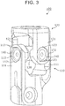
- FIG. 3 is a perspective view showing a schematic configuration of the first universal joint 100 according to the embodiment.
- FIG. 4 is an exploded perspective view showing a part of the first universal joint 100 according to the embodiment. Specifically, in FIG. 4 , the second yoke 120 of the first universal joint 100 is omitted.
- the first yoke 110 is made of, for example, aluminum, and includes a pair of arms 111 disposed to face each other.
- a through-hole 112 for fixing the bearing 140 is formed in each of the arms 111.
- the through-holes 112 of the arms 111 have the same axis.
- the axis is referred to as a first axis.
- the second yoke 120 is made of, for example, aluminum, and includes a pair of arms 121 disposed to face each other.
- a through-hole 122 for fixing the bearing 140 is formed in each of the arms 121.
- the through-holes 122 of the arms 121 have the same axis.
- the axis is referred to as a second axis.
- the first axis and the second axis are orthogonal to each other.
- the first yoke 110 and the second yoke 120 may be made of, for example, an iron-based metal.
- the joint spider 130 is made of iron, and has a body portion 131 and four shaft portions 132 projecting in four directions from side peripheral surfaces of the body portion 131.
- a pair of shaft portions 132 facing each other is attached to the through-holes 112 of the arms 111 provided in the first yoke 110 via the bearings 140.
- the remaining pair of shaft portions 132 among the four shaft portions 132 is attached to the through-holes 122 of the arms 121 provided in the second yoke 120 via the bearings 140.
- Each of the bearings 140 includes a cup 141 and a plurality of rolling elements 142 made of iron (see FIG. 5 ).
- the cup 141 has a bottomed cylindrical shape, and accommodates the rolling elements 142 therein.
- the rolling elements 142 are needle rollers arranged along a cylindrical inner peripheral surface of the cup 141.
- the inner peripheral surface of the cup 141 thus serves as a raceway surface for the rolling elements 142.
- Each of the bearings 140 is press-fitted into the through-holes 112 of the arms 111 and the through-holes 122 of the arms 121.
- Each shaft portion 132 of the joint spider 130 is press-fitted to each bearing 140.
- the shaft portions 132 of the joint spider 130 are rotatably supported by the bearings 140 with respect to the arms 111 and 121. Therefore, the joint spider 130 rotates about both the first axis and the second axis.
- the first yoke 110 is provided with recesses 113 each formed around each through-hole 112.
- the recesses 113 are portions formed by clinching, and through plastic deformation of the portions, the bearings 140 are fixed at predetermined positions in the through-holes 112.
- recesses 123 for fixing the bearings 140 are each formed around each through-hole 122.
- the manufacturing method for the universal joint according to the embodiment is described.
- a manufacturing method for the first universal joint 100 will be described as an example. Since the manufacturing method for the second universal joint 200 is the same as the manufacturing method for the first universal joint 100, the description thereof is omitted.
- a case where the joint spider 130 and the bearing 140 are assembled to the first yoke 110 in the first universal joint 100 is exemplified.
- the same manufacturing method is employed in a case where the joint spider 130 and the bearing 140 are assembled to the second yoke 120.
- FIG. 5 is an explanatory view showing a main configuration of the manufacturing apparatus 500 of the universal joint according to the embodiment.
- members other than the joint spider 130 are illustrated in a cross-sectional view.
- members other than the joint spider 130 are illustrated in a cross-sectional view.
- FIG. 5 a state before the first universal joint 100 is assembled is shown.
- the manufacturing apparatus 500 includes a yoke holding portion (not illustrated), a joint spider holding portion 510, a bearing holding portion 520, and a press-fit portion 530.
- the yoke holding portion is a portion for holding the first yoke 110 at a predetermined position during assembly.
- the yoke holding portion retains the first yoke 110 at a predetermined position even when pressure is applied from the press-fit portion 530 to the first yoke 110 during assembly.
- the joint spider holding portion 510 is a portion for holding the joint spider 130 with respect to the first yoke 110 held by the yoke holding portion.
- the joint spider holding portion 510 includes a pin member 511, and a distal end of the pin member 511 is fitted in the through-hole 112 of the first yoke 110.
- a recess 512 is formed on a distal end surface of the pin member 511, and the shaft portion 132 of the joint spider 130 is fitted into the recess 512. Thereby, a relative positional relationship between the joint spider 130 and the first yoke 110 is fixed.
- the shaft portion 132 opposite to the shaft portion 132 fitted in the recess 512 is positioned in the other through-hole 112 of the first yoke 110.
- the bearing 140 can be assembled to the shaft portion 132 opposite to the shaft portion 132 fitted in the recess 512, and to the other through-hole 112 of the first yoke 110.
- the shaft portion 132 to which the bearing 140 is assembled are referred to as a "shaft portion 132a”
- the through-hole 112 to which the bearing 140 is assembled are referred to as a "through-hole 112a”.
- the bearing holding portion 520 is a portion for holding the bearing 140 before assembly.
- the bearing holding portion 520 supports the bearing 140 to position the bearing 140 with respect to the shaft portion 132a and the through-hole 112a. Through the positioning of the bearing holding portion 520, the bearing 140 is disposed coaxially with the shaft portion 132a and the through-hole 112a.
- a press-fitting direction an axial direction after the positioning described above is performed and extending from the bearing 140 toward the joint spider 130
- the opposite direction will be referred to as a retracting direction.
- the bearing holding portion 520 descends from the position at which the bearing 140 is supported and retracts.
- the press-fit portion 530 is a portion for press-fitting the bearing 140 into the through-hole 112a of the first yoke 110 and the shaft portion 132a of the joint spider 130.
- the press-fit portion 530 includes a pedestal 531, a first shaft 532, and a second shaft 533.
- the pedestal 531 is a portion that moves while holding the first shaft 532 and the second shaft 533. Specifically, the pedestal 531 reciprocates in the axial direction or in a direction orthogonal to the axial direction (vertical direction in the embodiment) by power from a drive source (not illustrated).
- a drive source motors, such as a servomotor, are used, for example.
- the first shaft 532 is a portion for press-fitting the bearing 140 to a first position P1 (see FIG. 6 ) in the through-hole 112a of the first yoke 110 to temporarily assemble the bearing 140 with respect to the shaft portion 132a of the joint spider 130.
- the first shaft 532 is a cylindrical shaft elongated in the axial direction. A base end of the first shaft 532 is held by the pedestal 531.
- FIG. 6 is an explanatory view showing the manufacturing apparatus 500 for the universal joint according to the embodiment and showing a state in which the universal joint is temporarily assembled.
- an outer bottom surface of the cup 141 serves as a reference portion of the bearing 140.
- the first position P1 is a position upstream of a second position P2 in the press-fitting direction (see FIG. 9 ).
- the second position P2 is the final assembly position of the bearing 140.
- the second position P2 is located deeper in the through-hole 112a than the first position P1 is.
- the first position P1 is a position downstream of a position PF in the press-fitting direction.
- the outer bottom surface of the cup 141 of the bearing 140 and an outer surface of the arm 111 in the first yoke 110 are flush. That is, the first position P1 is disposed between the second position P2 and the position PF.
- the first shaft 532 press-fits the bearing 140 only to the first position P1 in the through-hole 112a, thereby temporarily assembling the bearing 140 with respect to the through-hole 112a and the shaft portion 132a of the joint spider 130.
- the second shaft 533 is a portion for press-fitting the bearing 140 at the first position P1 in the through-hole 112a to the second position P2.
- the second shaft 533 is a cylindrical shaft elongated in the axial direction.
- the second shaft 533 is disposed below the first shaft 532, and a base end of the second shaft 533 is held by the pedestal 531.
- a plurality of protrusions 534 projecting radially outward are provided on an outer peripheral surface at a distal end of the second shaft 533.
- distal end surfaces of the protrusions 534 abut against a periphery of the through-hole 112a of the first yoke 110 to clinch the abutting portions.
- the second shaft 533 further presses the bearing 140 into the through-hole 112a with clinched portions 119 (see FIG. 9 ) formed by the clinching, thereby press-fitting the bearing 140 to the second position P2.
- the clinched portions 119 are provided on the first yoke 110 at positions corresponding to the recesses 113 (see FIG. 3 ).
- FIGS. 7 to 9 are explanatory views showing processes of the manufacturing method for the universal joint according to the embodiment.
- FIG. 10 is a perspective view showing a relationship between the second shaft 533 and the first yoke 110 in FIG. 9 .
- the first yoke 110, the joint spider 130, and the bearing 140 are set in the manufacturing apparatus 500.
- the first yoke 110 is held by a yoke holding portion (not illustrated).
- the distal end of the pin member 511 of the joint spider holding portion 510 is fitted in the through-hole 112 of the first yoke 110, and the shaft portion 132 of the joint spider 130 is fitted in the recess 512 of the pin member 511.
- the shaft portion 132a opposite to the shaft portion 132 fitted in the recess 512 is positioned in the other through-hole 112a of the first yoke 110.
- the bearing 140 is supported by the bearing holding portion 520, whereby the bearing 140 is positioned with respect to the shaft portion 132a and the through-hole 112a. In this state, the bearing 140, the shaft portion 132a, the through-hole 112a, and the first shaft 532 are arranged on the same axis.
- FIG. 6 shows the state of each part in a first press-fitting process.
- the pedestal 531 of the press-fit portion 530 advances in the press-fitting direction
- the distal end surface of the first shaft 532 abuts against the bearing 140
- the bearing 140 is press-fitted to the first position P1 in the through-hole 112a.
- the bearing holding portion 520 is descended at an appropriate timing so that interference with the second shaft 533 is prevented.
- the bearing 140 is assembled to the shaft portion 132a of the joint spider 130 while entering the through-hole 112a through the press-fitting. Since the bearing 140 is press-fitted to the first position P1, the bearing 140 is disposed at a position away from the second position P2, which is the final assembly position, by a distance H. That is, the bearing 140 is in a temporarily assembled state.
- the pedestal 531 of the press-fit portion 530 moves in the retracting direction and then ascends, thereby retracting the first shaft 532 from a coaxis of the bearing 140 and disposing the second shaft 533 coaxially with the bearing 140.
- FIGS. 8 and 9 show the state of each part in a second press-fitting process. Specifically, as shown in FIG. 8 , when the pedestal 531 of the press-fit portion 530 advances in the press-fitting direction, the distal end surfaces of the protrusions 534 of the second shaft 533 abut against the periphery of the through-hole 112a of the first yoke 110. Subsequently, as shown in FIGS. 9 and 10 , when the pedestal 531 of the press-fit portion 530 further advances in the press-fitting direction, the distal end surfaces of the protrusions 534 of the second shaft 533 clinch the abutting portions to form the clinched portions 119.
- the second shaft 533 moves the bearing 140 from the first position P1 by the distance H, and press-fits the bearing 140 to the second position P2.
- the distance H is a length necessary for stably pressing the bearing 140 with the clinched portions 119, and is preferably 0.05 mm or more. Consequently, the bearing 140 is disposed at the final assembly position (second position P2).
- the manufacturing method for the universal joint includes the first press-fitting process and the second press-fitting process.
- the bearing 140 supporting the shaft portion 132a of the joint spider 130 so that the joint spider 130 is rotatable is press-fitted to the first position P1 in the through-hole 112a of the first yoke 110, whereby the bearing 140 is temporarily assembled with respect to the shaft portion 132a.
- the manufacturing apparatus 500 for the universal joint includes the first shaft 532 and the second shaft 533.
- the first shaft 532 press-fits the bearing 140, supporting the shaft portion 132a of the joint spider 130 such that the joint spider 130 is rotatable, to the first position P1 in the through-hole 112a of the first yoke 110 to temporarily assemble the bearing 140 with respect to the through-hole 112a and the shaft portion 132a.
- the second shaft 533 clinches the portion of the first yoke 110 around the through-hole 112a, and presses the bearing 140 deeper into the through-hole 112a with the clinched portions 119 formed by the clinching, to press-fit the bearing 140 to the second position P2 located deeper than the first position P1 in the through-hole 112a.
- the bearing 140 since the bearing 140 is positioned at the first position P1 during temporary assembly, even if there are individual differences in the dimensions of the through-hole 112a of the first yoke 110 or the bearing 140, the bearing 140 is reliably disposed at the first position P1. Thereafter, the bearing 140 is press-fitted to the second position P2 with the clinched portions 119. Therefore, the clinched portions 119 are reliably brought into contact with the bearing 140 disposed at the second position P2. Thus, even if there are individual differences in the dimensions of the through-hole 112a of the first yoke 110 or the bearing 140, it is possible to enhance reliability of the clinching with respect to these portions. This can suppress occurrence of looseness.
- the clinched portions 119 are reliably brought into contact with the bearing 140 such that generation of clearance between the bearing 140 and the first yoke 110 can be suppressed. Therefore, generation of abnormal noise can be suppressed.
- the distance H between the first position P1 and the second position P2 is 0.05 mm or more. Since the distance H between the first position P1 and the second position P2 is 0.05 mm or more, the bearing 140 can be stably press-fitted to the second position P2 with the clinched portions 119.
- the first yoke 110 and the bearing 140 are made of different metals.
- a difference in thermal expansion coefficient between the first yoke 110 and the bearing 140 may cause insufficient press-fitting of the bearing 140.
- the bearing 140 is press-fitted with the clinched portions 119 formed through plastic deformation, even if there is a difference in the thermal expansion coefficient, it is possible to enhance the reliability of the press-fitting.
- thickness of the clinched portions 119 can be sufficiently secured, so that the reliability of press-fitting can be further enhanced.
- the first shaft 532 and the second shaft 533 are integrated. Since the first shaft 532 and the second shaft 533 are integrated via the pedestal 531, the configuration and mechanism of the press-fit portion 530 can be simplified.
- the configuration of the manufacturing apparatus for the universal joint is not limited to the configuration described in the above embodiment.
- a modification of the manufacturing apparatus for the universal joint is described below focusing on the difference from the above embodiment.
- the same components as those in the above embodiment or the other modifications may be given the same reference numerals and descriptions thereof may be omitted.
- FIG. 11 is an explanatory view showing a main configuration of a manufacturing apparatus 500A for a universal joint according to a first modification.
- members other than the joint spider 130 are illustrated in a cross-sectional view. The same applies to FIGS. 12 and 13 .
- the press-fit portion 530a is different from the press-fit portion 530 of the manufacturing apparatus 500 according to the embodiment.
- the press-fit portion 530a will be described in detail.
- the press-fit portion 530a according to the first modification differs from the press-fit portion 530 of the manufacturing apparatus 500 according to the embodiment in that a first shaft 532a is built in a second shaft 533a so as to be advanceable and retractable.
- the press-fit portion 530a includes a support portion 531a, the first shaft 532a, the second shaft 533a, a first pressing portion 535a, and a second pressing portion 536a.
- the support portion 531a is a portion supporting the second shaft 533a, in which the first shaft 532a is built, such that the second shaft 533a is slidable in the axial direction.
- a through-hole 5311 penetrating in the axial direction is formed in the support portion 531a, and the second shaft 533a is slidably fitted in the through-hole 5311. Thereby, positional deviation of the second shaft 533a in the direction orthogonal to the axial direction is restricted.
- the first shaft 532a is a portion for press-fitting the bearing 140 to the first position P1 (see FIG. 12 ) in the through-hole 112a of the first yoke 110 to temporarily assemble the bearing 140 with respect to the shaft portion 132a of the joint spider 130.
- the first shaft 532a is a cylindrical shaft elongated in the axial direction. A base end of the first shaft 532a is connected to the first pressing portion 535a.
- the second shaft 533a is a portion for press-fitting the bearing 140 at the first position P1 in the through-hole 112a to the second position P2 (see FIG. 13 ).
- the second shaft 533a is a cylindrical shaft elongated in the axial direction.
- the base end of the second shaft 533a is connected to the second pressing portion 536a.
- the first shaft 532a is slidably fitted in a hollow portion of the second shaft 533a. This allows relative movement of the second shaft 533a and the first shaft 532a on the same axis. That is, the first shaft 532a can be advanced and retracted from a distal end of the second shaft 533a.
- a plurality of protrusions 534a protruding radially outward are provided on an outer peripheral surface at the distal end of the second shaft 533a.
- distal end surfaces of the protrusions 534a abut against a periphery of the through-hole 112a of the first yoke 110 to clinch the abutting portions.
- the second shaft 533a further presses the bearing 140 into the through-hole 112a with the clinched portions 119 (see FIG. 13 ) formed by the clinching, thereby press-fitting the bearing 140 to the second position P2.
- the first pressing portion 535a is a cylindrical shaft elongated in the axial direction, and its distal end is connected to the first shaft 532a.
- the first pressing portion 535a reciprocates in the axial direction by power from a drive source (not illustrated). Thereby, the first pressing portion 535a reciprocates the first shaft 532a in the axial direction.
- the second pressing portion 536a is a cylindrical shaft elongated in the axial direction, and its distal end is connected to the second shaft 533a.
- the first shaft 532a and the first pressing portion 535a are inserted into a hollow portion of the second pressing portion 536a.
- movement of the first shaft 532a and the first pressing portion 535a does not inhibit movement of the second pressing portion 536a.
- the second pressing portion 536a reciprocates in the axial direction by power from a driving source (not illustrated) different from the driving source for the first pressing portion 535a. Thereby, the second pressing portion 536a reciprocates the second shaft 533a in the axial direction.
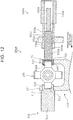
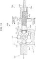
- FIGS. 12 and 13 are explanatory views showing processes of the manufacturing method for the universal joint according to the first modification.
- the first yoke 110, the joint spider 130, and the bearing 140 are set in the manufacturing apparatus 500A.
- the bearing 140, the shaft portion 132a, the through-hole 112a, the first shaft 532a, and the second shaft 533a are arranged on the same axis.
- FIG. 12 shows the state of each part in the first press-fitting process in the first modification.
- the first shaft 532a is also pressed and advances in the press-fitting direction.
- the distal end surface of the first shaft 532a abuts against the bearing 140, and the bearing 140 is press-fitted into the through-hole 112a to the first position P1.
- the bearing holding portion 520 is descended at an appropriate timing so that interference with the second shaft 533a is prevented.
- the bearing 140 is assembled to the shaft portion 132a of the joint spider 130 while entering the through-hole 112a through the press-fitting. With the bearing 140 press-fitted to the first position P1, the bearing 140 is in a temporarily assembled state.
- FIG. 13 shows the state of each part in the second press-fitting process according to the first modification. Specifically, as shown in FIG. 13 , while the second pressing portion 536a advances in the press-fitting direction, the first pressing portion 535a retracts in a retracting direction. Thereby, the second shaft 533a advances in the press-fitting direction to press-fit the bearing 140, whereas the first shaft 532a retracts in the retracting direction and retracts from the bearing 140. The first shaft 532a and the second shaft 533a may be retracted simultaneously.
- the distal end surfaces of the protrusions 534a abut against the periphery of the through-hole 112a of the first yoke 110. Subsequently, the distal end surfaces of the protrusions 534a clinch the abutting portions to form the clinched portions 119.
- the second shaft 533a further presses the bearing 140 into the through-hole 112a with the clinched portions 119, thereby press-fitting the bearing 140 from the first position P1 to the second position P2. Consequently, the bearing 140 is disposed at the final assembly position (second position P2).
- the first shaft 532a is built in the second shaft 533a so as to be advanceable and retractable.
- the first shaft 532a and the second shaft 533a can be coaxially arranged and the press-fit portion 530a can be reduced in size.
- the first press-fitting process and the second press-fitting process can be performed without exchanging the positions of the first shaft 532a and the second shaft 533a, it is possible to shorten the manufacturing time.
- FIG. 14 is an explanatory view showing a main configuration of a manufacturing apparatus 500B for a universal joint according to a second modification.
- members other than the joint spider 130 are illustrated in a cross-sectional view. The same applies to FIGS. 15 and 16 .
- a press-fit portion 530b is different from the press-fit portion 530a of the manufacturing apparatus 500A according to the first modification.
- the following describes the press-fit portion 530b in detail.
- the manufacturing apparatus 500B according to the second modification differs from the manufacturing apparatus 500A according to the first modification in that the press-fit portion 530b is provided with a switching mechanism 540b.
- the switching mechanism 540b connects a first shaft 532b and a second shaft 533b when the first shaft 532b press-fits the bearing 140 to the first position P1, and releases the connection when the bearing 140 is press-fitted to the second position P2.
- the press-fit portion 530b includes the support portion 531a, the first shaft 532b, the second shaft 533b, a first pressing portion 535b, a second pressing portion 536b, and the switching mechanism 540b.
- the first shaft 532b is a portion for press-fitting the bearing 140 to the first position P1 (see FIG. 15 ) in the through-hole 112a of the first yoke 110 to temporarily assemble the bearing 140 with respect to the shaft portion 132a of the joint spider 130.
- the first shaft 532b is a cylindrical shaft elongated in the axial direction, and a base end portion thereof serves as a large diameter portion 5321 having a diameter larger than that of other portions.
- the base end of the first shaft 532b is connected to the first pressing portion 535b.
- the second shaft 533b is a portion for press-fitting the bearing 140 at the first position P1 in the through-hole 112a to the second position P2 (see FIG. 16 ).
- the second shaft 533b is a cylindrical shaft elongated in the axial direction.
- a base end of the second shaft 533b is connected to the second pressing portion 536b.
- a hollow portion of the second shaft 533b has a shape corresponding to an outer shape of the first shaft 532b.
- the hollow portion of the second shaft 533b has, on its base end side, an opening 5331 whose diameter is larger than that of the other portions.
- the large diameter portion 5321 of the first shaft 532b fits into the opening 5331 having a large diameter.
- the second shaft 533b advances in the press-fitting direction but does not retract in the retracting direction with respect to the first shaft 532b.
- the first shaft 532b can move with the second shaft 533b in the press-fitting direction, and can be separated from the second shaft 533b in the retracting direction.
- a plurality of protrusions 534b protruding radially outward are provided on the outer peripheral surface at the distal end of the second shaft 533b.
- distal end surfaces of the protrusions 534b abut against a periphery of the through-hole 112a of the first yoke 110 to clinch the abutting portions.
- the second shaft 533b further presses the bearing 140 into the through-hole 112a with the clinched portions 119 (see FIG. 16 ) formed by the clinching, thereby press-fitting the bearing 140 to the second position P2.
- the first pressing portion 535b is a cylindrical shaft elongated in the axial direction, and its distal end is connected to the first shaft 532b.
- the switching mechanism 540b is detachably connected to the base end of the first pressing portion 535b.
- the second pressing portion 536b is a cylindrical shaft elongated in the axial direction, and its distal end is connected to the second shaft 533b.
- the switching mechanism 540b is attached to the second pressing portion 536b.
- the first pressing portion 535b is disposed in a hollow portion of the second pressing portion 536b.
- the second pressing portion 536b reciprocates in the axial direction by power from a drive source (not illustrated). Thereby, the second pressing portion 536b reciprocates the second shaft 533b in the axial direction.
- the switching mechanism 540b is, for example, a solenoid, and includes a main body portion 541 and a movable shaft 542 that is advanceable and retractable with respect to the main body portion 541.
- the main body portion 541 is fixed to the second pressing portion 536b.
- the movable shaft 542 is normally disposed inside of the second pressing portion 536b so as to extend from the main body portion 541, and is retracted into the main body portion 541 in the second press-fitting process (see FIG. 16 ).
- the switching mechanism 540b may be an air cylinder.
- FIG. 15 is an explanatory view showing the switching mechanism 540b according to the second modification in a normal state.
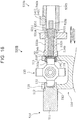
- FIG. 16 is an explanatory view showing a second press-fitting process of the switching mechanism 540b according to the second modification.
- the movable shaft 542 abuts against the base end of the first pressing portion 535b, and the first shaft 532b and the second shaft 533b are connected to each other via the first pressing portion 535b, the second pressing portion 536b, and the switching mechanism 540b.
- the second pressing portion 536b moves in the press-fitting direction
- the second shaft 533b is pressed by the second pressing portion 536b and moves in the press-fitting direction.
- the movable shaft 542 moves the first pressing portion 535b in the press-fitting direction, and the first shaft 532b is also moved in the press-fitting direction.
- the movable shaft 542 is separated from the base end of the first pressing portion 535b, and the connection between the first shaft 532b and the second shaft 533b is released.
- the second pressing portion 536b moves in the press-fitting direction
- the second shaft 533b is pressed by the second pressing portion 536b and moves in the press-fitting direction.
- the first pressing portion 535b and the first shaft 532b do not move.
- FIGS. 14 to 16 show processes of a manufacturing method for a universal joint according to the second modification.
- the first yoke 110, the joint spider 130, and the bearing 140 are set in the manufacturing apparatus 500B.
- the bearing 140, the shaft portion 132a, the through-hole 112a, the first shaft 532b, and the second shaft 533b are arranged on the same axis.
- FIG. 15 shows the state of each part in the first press-fitting process in the second modification.
- the switching mechanism 540b connects the first shaft 532b and the second shaft 533b to each other. Therefore, when the second pressing portion 536b of the press-fit portion 530b advances in the press-fitting direction, the first shaft 532b and the second shaft 533b also advance in the press-fitting direction.
- the bearing 140 is press-fitted to the first position P1 in the through-hole 112a.
- the bearing holding portion 520 is descended at an appropriate timing so that interference with the second shaft 533b is prevented.
- the bearing 140 is assembled to the shaft portion 132a of the joint spider 130 while entering the through-hole 112a. With the bearing 140 press-fitted to the first position P1, the bearing 140 is in a temporarily assembled state.
- FIG. 16 shows the state of each part in the second press-fitting process according to the second modification.
- the switching mechanism 540b releases the connection between the first shaft 532b and the second shaft 533b. Therefore, when the second pressing portion 536b of the press-fit portion 530b advances in the press-fitting direction, only the second shaft 533b advances in the press-fitting direction.
- the distal end surfaces of the protrusions 534b abut against the periphery of the through-hole 112a of the first yoke 110.
- the distal end surfaces of the protrusions 534b clinch the abutting portions to form the clinched portions 119.
- the second shaft 533b further presses the bearing 140 into the through-hole 112a with the clinched portions 119, thereby press-fitting the bearing 140 from the first position P1 to the second position P2. Consequently, the bearing 140 is disposed at the final assembly position (second position P2).
- the second shaft 533b When the second pressing portion 536b moves in the retracting direction, the second shaft 533b also moves in the retracting direction. During this movement, since the large diameter portion 5321 of the first shaft 532b fits into the opening 5331 of the second shaft 533b, the first shaft 532b is also pushed by the second shaft 533b in the retracting direction.
- the manufacturing apparatus 500B includes the switching mechanism 540b that connects the first shaft 532b and the second shaft 533b when the first shaft 532b press-fits the bearing 140 to the first position P1, and releases the connection when the bearing 140 is press-fitted to the second position P2.
- the switching mechanism 540b connects the first shaft 532b and the second shaft 533b to each other, and when the second shaft 533b press-fits the bearing 140 to the second position P2, the connection is released.
- the first press-fitting process and the second press-fitting process can be performed with one drive source for press-fitting, and the manufacturing apparatus 500B itself can be reduced in size.
- the embodiment exemplifies a case where the shaft portion 132a of the joint spider 130 and the bearing 140 are assembled to one of the arms 111 of the first yoke 110.
- the shaft portion 132a of the joint spider 130 and the bearing 140 may be assembled simultaneously to both of the arms 111.
- the first universal joint 100 provided in the steering system 10 of an automobile is exemplified as the universal joint according to the present invention.
- the manufacturing method and manufacturing apparatus according to the present invention it is possible to apply the manufacturing method and manufacturing apparatus according to the present invention to universal joints provided in other devices.
- the present invention is applicable to a manufacturing method and a manufacturing apparatus for a universal joint having a joint spider and a bearing.
Landscapes
- Engineering & Computer Science (AREA)
- General Engineering & Computer Science (AREA)
- Mechanical Engineering (AREA)
- Automatic Assembly (AREA)
- Steering Controls (AREA)
- Forging (AREA)
Abstract
Description
- The present invention relates to a manufacturing method and a manufacturing apparatus for a universal joint.
- For example, a cross joint having a joint spider and a plurality of bearings is used in a steering apparatus for an automobile to connect a steering shaft and a pinion shaft (see, for example, Japanese Unexamined Patent Application Publication No.
2015-224682 JP 2015-224682 A - There are dimensional variations in the through-hole of the yoke or the bearing within a tolerance range, causing individual differences. Since the clinching described above is performed at a constant amount, the clinching cannot be reliably performed depending on the dimensions of the through-hole of the yoke or the bearing, and looseness may occur.
- In addition, the bearing of the cross joint has a negative clearance with respect to the through-hole of the yoke, and is held by being press-fitted to the through-hole. The amount of negative clearance may decrease due to, for example, manufacturing errors of the yoke and the bearing, and differences in linear thermal expansion coefficient of the yoke and the bearing. Therefore, the clinching is applied around the through-hole of the yoke to restrain the bearing from falling off in the axial direction (as a fail-safe function). It is not essential to bring a clinched portion produced by clinching into contact with the bearing to achieve the fail-safe function. That is, when there is a clearance between the clinched portion and the bearing, the bearing and the clinched portion may come in contact with each other while a vehicle is traveling, which may cause noise.
- The present invention provides a manufacturing method and a manufacturing apparatus for a universal joint that enable enhancing the reliability of the clinching with respect to the yoke and the bearing.
- A method of manufacturing a universal joint according to a first aspect of the present invention includes: temporarily assembling a bearing, which supports a shaft portion of a joint spider such that the shaft portion is rotatable, with respect to a through-hole and the shaft portion by press-fitting the bearing to a first position in the through-hole of a yoke; and clinching, after the bearing is temporarily assembled, a portion of the yoke around the through-hole, and pressing the bearing deeper into the through-hole with a clinched portion formed by the clinching to press-fit the bearing to a second position located deeper than the first position in the through-hole.
- In the method according to the above aspect, a distance between the first position and the second position may be 0.05 mm or more.
- In the method according to the above aspect, the yoke and the bearing may be made of different metals.
- A manufacturing apparatus for a universal joint according to a second aspect of the present invention includes a first shaft and a second shaft. The first shaft is configured to press-fit a bearing, which supports a shaft portion of a joint spider such that the shaft portion is rotatable, to a first position in a through-hole of a yoke, to temporarily assemble the bearing with respect to the through-hole and the shaft portion. The second shaft is configured to clinch, after the bearing is temporarily assembled, a portion of the yoke around the through-hole, and press the bearing deeper into the through-hole with a clinched portion formed by the clinching to press-fit the bearing to a second position located deeper than the first position in the through-hole.
- In the apparatus according to the above aspect, the first shaft and the second shaft may be integrated.
- In the apparatus according to the above aspect, the first shaft may be built in the second shaft so as to be advanceable and retractable.
- The apparatus according to the above aspect may further include a switching mechanism. The switching mechanism may be configured to: bring the first shaft into connection with the second shaft when the first shaft press-fits the bearing to the first position; and release the connection when the bearing is press-fitted to the second position.
- In the apparatus according to the above aspect, a distance between the first position and the second position may be 0.05 mm or more.
- In the apparatus according to the above aspect, the yoke and the bearing may be made of different metals.
- According to the first and second aspects of the present invention, it is possible to increase the reliability of the clinching with respect to the yoke and the bearing.
- Features, advantages, and technical and industrial significance of exemplary embodiments of the invention will be described below with reference to the accompanying drawings, in which like numerals denote like elements, and wherein:
-
FIG. 1 is a schematic view showing an example of usage of a universal joint according to an embodiment; -
FIG. 2 is a perspective view showing a schematic configuration of an intermediate shaft according to the embodiment; -
FIG. 3 is a perspective view showing a schematic configuration of a first universal joint according to the embodiment; -
FIG. 4 is an exploded perspective view showing a part of the first universal joint according to the embodiment; -
FIG. 5 is an explanatory view showing a main configuration of a manufacturing apparatus for the universal joint according to the embodiment; -
FIG. 6 is an explanatory view showing the manufacturing apparatus for the universal joint according to the embodiment and showing a state in which the universal joint is temporarily assembled; -
FIG. 7 is an explanatory view showing a process of a manufacturing method for the universal joint according to the embodiment; -
FIG. 8 is an explanatory view showing another process of the manufacturing method for the universal joint according to the embodiment; -
FIG. 9 is an explanatory view showing yet another process of the manufacturing method for the universal joint according to the embodiment; -
FIG. 10 is a perspective view showing a relationship between a second shaft and a first yoke inFIG. 9 ; -
FIG. 11 is an explanatory view showing a main configuration of a manufacturing apparatus for a universal joint according to a first modification; -
FIG. 12 is an explanatory view showing a process of a manufacturing method for the universal joint according to the first modification; -
FIG. 13 is an explanatory view showing another process of the manufacturing method for the universal joint according to the first modification; -
FIG. 14 is an explanatory view showing a main configuration of the manufacturing apparatus for the universal joint according to the first modification; -
FIG. 15 is an explanatory view showing a normal state of a switching mechanism according to a second modification; and -
FIG. 16 is an explanatory view showing a second press-fitting process of the switching mechanism according to the second modification. - Hereinafter, the embodiment will be specifically described below with reference to the drawings. It should be noted that any embodiment described below illustrates a comprehensive or specific example. The numerical values, shapes, materials, components, arrangement positions and connection forms of the components, and the like described in the following embodiment are merely examples, and are not intended to limit the present invention. Further, among the components in the following embodiment, components not described in the independent claims indicating the highest concept are described as optional components.
- It should be noted that the drawings are schematic, in which emphasis, omission, and ratio adjustment are made as appropriate to illustrate the present invention, and may differ from actual shapes, positional relationships, and ratios.
-
FIG. 1 is a schematic view showing an example of usage of a universal joint according to an embodiment. As shown inFIG. 1 , universal joints (a firstuniversal joint 100 and a second universal joint 200) are provided in anintermediate shaft 20 included in, for example, asteering system 10 of an automobile. Specifically, thesteering system 10 includes asteering shaft 12, asteering operation mechanism 16, and theintermediate shaft 20. Asteering wheel 11 is connected at one end of thesteering shaft 12. Thesteering operation mechanism 16 is composed of a rack and pinion mechanism including apinion shaft 13 and arack shaft 14 to steer steeredwheels 15. Theintermediate shaft 20 is interposed between thesteering shaft 12 and thepinion shaft 13 to transmit steering torque. - One end of the
intermediate shaft 20 is connected to thesteering shaft 12 via the firstuniversal joint 100. The other end of theintermediate shaft 20 is connected to thepinion shaft 13 via the seconduniversal joint 200. - When the
steering wheel 11 is operated to rotate thesteering shaft 12, the rotation is transmitted to thepinion shaft 13 and therack shaft 14 via theintermediate shaft 20. Thus, thesteering operation mechanism 16 steers the steeredwheels 15. -
FIG. 2 is a perspective view showing a schematic configuration of theintermediate shaft 20 according to the embodiment. As shown inFIG. 2 , theintermediate shaft 20 includes an extendable andretractable center shaft 21, the firstuniversal joint 100 provided at one end of thecenter shaft 21, and the seconduniversal joint 200 provided at the other end of thecenter shaft 21. - The first
universal joint 100 includes afirst yoke 110 coupled to the one end of thecenter shaft 21, asecond yoke 120 coupled to the steeringshaft 12, ajoint spider 130 connecting thefirst yoke 110 and thesecond yoke 120 to each other, and a plurality ofbearings 140 supporting shaft portions 132 (seeFIG. 4 ) of thejoint spider 130 such that theshaft portions 132 are rotatable. - The second
universal joint 200 includes afirst yoke 210 coupled to the other end of thecenter shaft 21, asecond yoke 220 coupled to thepinion shaft 13, ajoint spider 230 connecting thefirst yoke 210 and thesecond yoke 220 to each other, and a plurality ofbearings 240 supporting shaft portions (not illustrated) of thejoint spider 230 such that the shaft portions are rotatable. - The first
universal joint 100 will be described in detail below. Since the firstuniversal joint 100 and the seconduniversal joint 200 basically have the same configuration, details of the seconduniversal joint 200 will be omitted. -
FIG. 3 is a perspective view showing a schematic configuration of the firstuniversal joint 100 according to the embodiment.FIG. 4 is an exploded perspective view showing a part of the firstuniversal joint 100 according to the embodiment. Specifically, inFIG. 4 , thesecond yoke 120 of the firstuniversal joint 100 is omitted. - As shown in
FIGS. 3 and4 , thefirst yoke 110 is made of, for example, aluminum, and includes a pair ofarms 111 disposed to face each other. A through-hole 112 for fixing thebearing 140 is formed in each of thearms 111. The through-holes 112 of thearms 111 have the same axis. The axis is referred to as a first axis. - As shown in
FIG. 3 , thesecond yoke 120 is made of, for example, aluminum, and includes a pair ofarms 121 disposed to face each other. A through-hole 122 for fixing thebearing 140 is formed in each of thearms 121. The through-holes 122 of thearms 121 have the same axis. The axis is referred to as a second axis. The first axis and the second axis are orthogonal to each other. Thefirst yoke 110 and thesecond yoke 120 may be made of, for example, an iron-based metal. - As shown in
FIG. 4 , thejoint spider 130 is made of iron, and has abody portion 131 and fourshaft portions 132 projecting in four directions from side peripheral surfaces of thebody portion 131. Among the fourshaft portions 132, a pair ofshaft portions 132 facing each other is attached to the through-holes 112 of thearms 111 provided in thefirst yoke 110 via thebearings 140. The remaining pair ofshaft portions 132 among the fourshaft portions 132 is attached to the through-holes 122 of thearms 121 provided in thesecond yoke 120 via thebearings 140. - Each of the
bearings 140 includes acup 141 and a plurality of rollingelements 142 made of iron (seeFIG. 5 ). Thecup 141 has a bottomed cylindrical shape, and accommodates the rollingelements 142 therein. The rollingelements 142 are needle rollers arranged along a cylindrical inner peripheral surface of thecup 141. The inner peripheral surface of thecup 141 thus serves as a raceway surface for the rollingelements 142. - Each of the
bearings 140 is press-fitted into the through-holes 112 of thearms 111 and the through-holes 122 of thearms 121. Eachshaft portion 132 of thejoint spider 130 is press-fitted to eachbearing 140. Thus, theshaft portions 132 of thejoint spider 130 are rotatably supported by thebearings 140 with respect to thearms joint spider 130 rotates about both the first axis and the second axis. - As shown in
FIG. 3 , thefirst yoke 110 is provided withrecesses 113 each formed around each through-hole 112. Therecesses 113 are portions formed by clinching, and through plastic deformation of the portions, thebearings 140 are fixed at predetermined positions in the through-holes 112. Similarly, in thesecond yoke 120, recesses 123 for fixing thebearings 140 are each formed around each through-hole 122. - Next, the manufacturing method for the universal joint according to the embodiment is described. In the following description, a manufacturing method for the first
universal joint 100 will be described as an example. Since the manufacturing method for the seconduniversal joint 200 is the same as the manufacturing method for the firstuniversal joint 100, the description thereof is omitted. Here, a case where thejoint spider 130 and thebearing 140 are assembled to thefirst yoke 110 in the firstuniversal joint 100 is exemplified. The same manufacturing method is employed in a case where thejoint spider 130 and thebearing 140 are assembled to thesecond yoke 120. - First, a
manufacturing apparatus 500 used in the manufacturing method for the universal joint is described.FIG. 5 is an explanatory view showing a main configuration of themanufacturing apparatus 500 of the universal joint according to the embodiment. InFIG. 5 , members other than thejoint spider 130 are illustrated in a cross-sectional view. Also inFIGS. 6 to 9 , members other than thejoint spider 130 are illustrated in a cross-sectional view. InFIG. 5 , a state before the firstuniversal joint 100 is assembled is shown. - The
manufacturing apparatus 500 includes a yoke holding portion (not illustrated), a jointspider holding portion 510, abearing holding portion 520, and a press-fit portion 530. - The yoke holding portion is a portion for holding the
first yoke 110 at a predetermined position during assembly. The yoke holding portion retains thefirst yoke 110 at a predetermined position even when pressure is applied from the press-fit portion 530 to thefirst yoke 110 during assembly. - The joint
spider holding portion 510 is a portion for holding thejoint spider 130 with respect to thefirst yoke 110 held by the yoke holding portion. Specifically, the jointspider holding portion 510 includes apin member 511, and a distal end of thepin member 511 is fitted in the through-hole 112 of thefirst yoke 110. Arecess 512 is formed on a distal end surface of thepin member 511, and theshaft portion 132 of thejoint spider 130 is fitted into therecess 512. Thereby, a relative positional relationship between thejoint spider 130 and thefirst yoke 110 is fixed. In this state, theshaft portion 132 opposite to theshaft portion 132 fitted in therecess 512 is positioned in the other through-hole 112 of thefirst yoke 110. Through this positioning, the bearing 140 can be assembled to theshaft portion 132 opposite to theshaft portion 132 fitted in therecess 512, and to the other through-hole 112 of thefirst yoke 110. Hereinafter, theshaft portion 132 to which thebearing 140 is assembled are referred to as a "shaft portion 132a", and the through-hole 112 to which thebearing 140 is assembled are referred to as a "through-hole 112a". Through the positioning of the jointspider holding portion 510, theshaft portion 132a and the through-hole 112a are coaxially arranged. - The
bearing holding portion 520 is a portion for holding thebearing 140 before assembly. Thebearing holding portion 520 supports the bearing 140 to position the bearing 140 with respect to theshaft portion 132a and the through-hole 112a. Through the positioning of thebearing holding portion 520, thebearing 140 is disposed coaxially with theshaft portion 132a and the through-hole 112a. Hereinafter, an axial direction after the positioning described above is performed and extending from the bearing 140 toward thejoint spider 130 will be referred to as a press-fitting direction, and the opposite direction will be referred to as a retracting direction. After thebearing 140 is press-fitted by the press-fit portion 530, thebearing holding portion 520 descends from the position at which thebearing 140 is supported and retracts. - The press-
fit portion 530 is a portion for press-fitting thebearing 140 into the through-hole 112a of thefirst yoke 110 and theshaft portion 132a of thejoint spider 130. Specifically, the press-fit portion 530 includes apedestal 531, afirst shaft 532, and asecond shaft 533. - The
pedestal 531 is a portion that moves while holding thefirst shaft 532 and thesecond shaft 533. Specifically, thepedestal 531 reciprocates in the axial direction or in a direction orthogonal to the axial direction (vertical direction in the embodiment) by power from a drive source (not illustrated). As a drive source, motors, such as a servomotor, are used, for example. - The
first shaft 532 is a portion for press-fitting thebearing 140 to a first position P1 (seeFIG. 6 ) in the through-hole 112a of thefirst yoke 110 to temporarily assemble thebearing 140 with respect to theshaft portion 132a of thejoint spider 130. Specifically, thefirst shaft 532 is a cylindrical shaft elongated in the axial direction. A base end of thefirst shaft 532 is held by thepedestal 531. When thefirst shaft 532 moves closer to thejoint spider 130 in the press-fitting direction through the movement of thepedestal 531, the distal end surface of thefirst shaft 532 abuts against the bearing 140, and thebearing 140 is inserted into the through-hole 112a to the first position P1. -
FIG. 6 is an explanatory view showing themanufacturing apparatus 500 for the universal joint according to the embodiment and showing a state in which the universal joint is temporarily assembled. Here, an outer bottom surface of thecup 141 serves as a reference portion of thebearing 140. As shown inFIG. 6 , the first position P1 is a position upstream of a second position P2 in the press-fitting direction (seeFIG. 9 ). The second position P2 is the final assembly position of thebearing 140. The second position P2 is located deeper in the through-hole 112a than the first position P1 is. The first position P1 is a position downstream of a position PF in the press-fitting direction. At the position PF, the outer bottom surface of thecup 141 of thebearing 140 and an outer surface of thearm 111 in thefirst yoke 110 are flush. That is, the first position P1 is disposed between the second position P2 and the position PF. Thefirst shaft 532 press-fits the bearing 140 only to the first position P1 in the through-hole 112a, thereby temporarily assembling the bearing 140 with respect to the through-hole 112a and theshaft portion 132a of thejoint spider 130. - The
second shaft 533 is a portion for press-fitting thebearing 140 at the first position P1 in the through-hole 112a to the second position P2. Specifically, thesecond shaft 533 is a cylindrical shaft elongated in the axial direction. Thesecond shaft 533 is disposed below thefirst shaft 532, and a base end of thesecond shaft 533 is held by thepedestal 531. - On an outer peripheral surface at a distal end of the
second shaft 533, a plurality ofprotrusions 534 projecting radially outward are provided. When thesecond shaft 533 moves closer to thejoint spider 130 in the press-fitting direction through the movement of thepedestal 531, distal end surfaces of theprotrusions 534 abut against a periphery of the through-hole 112a of thefirst yoke 110 to clinch the abutting portions. Thesecond shaft 533 further presses the bearing 140 into the through-hole 112a with clinched portions 119 (seeFIG. 9 ) formed by the clinching, thereby press-fitting thebearing 140 to the second position P2. The clinchedportions 119 are provided on thefirst yoke 110 at positions corresponding to the recesses 113 (seeFIG. 3 ). - Next, a manufacturing method for a universal joint using the
manufacturing apparatus 500 will be described based onFIGS. 5 to 10 .FIGS. 7 to 9 are explanatory views showing processes of the manufacturing method for the universal joint according to the embodiment.FIG. 10 is a perspective view showing a relationship between thesecond shaft 533 and thefirst yoke 110 inFIG. 9 . - As shown in
FIG. 5 , first, thefirst yoke 110, thejoint spider 130, and thebearing 140 are set in themanufacturing apparatus 500. Specifically, thefirst yoke 110 is held by a yoke holding portion (not illustrated). The distal end of thepin member 511 of the jointspider holding portion 510 is fitted in the through-hole 112 of thefirst yoke 110, and theshaft portion 132 of thejoint spider 130 is fitted in therecess 512 of thepin member 511. In this state, theshaft portion 132a opposite to theshaft portion 132 fitted in therecess 512 is positioned in the other through-hole 112a of thefirst yoke 110. Thebearing 140 is supported by thebearing holding portion 520, whereby thebearing 140 is positioned with respect to theshaft portion 132a and the through-hole 112a. In this state, thebearing 140, theshaft portion 132a, the through-hole 112a, and thefirst shaft 532 are arranged on the same axis. -
FIG. 6 shows the state of each part in a first press-fitting process. As shown inFIG. 6 , when thepedestal 531 of the press-fit portion 530 advances in the press-fitting direction, the distal end surface of thefirst shaft 532 abuts against the bearing 140, and thebearing 140 is press-fitted to the first position P1 in the through-hole 112a. While the press-fitting is performed, thebearing holding portion 520 is descended at an appropriate timing so that interference with thesecond shaft 533 is prevented. Thebearing 140 is assembled to theshaft portion 132a of thejoint spider 130 while entering the through-hole 112a through the press-fitting. Since thebearing 140 is press-fitted to the first position P1, thebearing 140 is disposed at a position away from the second position P2, which is the final assembly position, by a distance H. That is, thebearing 140 is in a temporarily assembled state. - Next, as shown in
FIG. 7 , thepedestal 531 of the press-fit portion 530 moves in the retracting direction and then ascends, thereby retracting thefirst shaft 532 from a coaxis of thebearing 140 and disposing thesecond shaft 533 coaxially with thebearing 140. -
FIGS. 8 and9 show the state of each part in a second press-fitting process. Specifically, as shown inFIG. 8 , when thepedestal 531 of the press-fit portion 530 advances in the press-fitting direction, the distal end surfaces of theprotrusions 534 of thesecond shaft 533 abut against the periphery of the through-hole 112a of thefirst yoke 110. Subsequently, as shown inFIGS. 9 and 10 , when thepedestal 531 of the press-fit portion 530 further advances in the press-fitting direction, the distal end surfaces of theprotrusions 534 of thesecond shaft 533 clinch the abutting portions to form the clinchedportions 119. By pressing thebearing 140 further into the through-hole 112a with the clinchedportions 119, thesecond shaft 533 moves the bearing 140 from the first position P1 by the distance H, and press-fits the bearing 140 to the second position P2. The distance H is a length necessary for stably pressing thebearing 140 with the clinchedportions 119, and is preferably 0.05 mm or more. Consequently, thebearing 140 is disposed at the final assembly position (second position P2). - As described above, the manufacturing method for the universal joint according to the embodiment includes the first press-fitting process and the second press-fitting process. In the first press-fitting process, the bearing 140 supporting the
shaft portion 132a of thejoint spider 130 so that thejoint spider 130 is rotatable is press-fitted to the first position P1 in the through-hole 112a of thefirst yoke 110, whereby thebearing 140 is temporarily assembled with respect to theshaft portion 132a. In the second press-fitting process, after the first press-fitting process, a portion of thefirst yoke 110 around the through-hole 112a is clinched, and thebearing 140 is pressed deeper into the through-hole 112a with the clinchedportions 119 formed by the clinching, thereby thebearing 140 is press-fitted to the second position P2 located deeper than the first position P1 in the through-hole 112a. - Further, the
manufacturing apparatus 500 for the universal joint according to the embodiment includes thefirst shaft 532 and thesecond shaft 533. Thefirst shaft 532 press-fits thebearing 140, supporting theshaft portion 132a of thejoint spider 130 such that thejoint spider 130 is rotatable, to the first position P1 in the through-hole 112a of thefirst yoke 110 to temporarily assemble thebearing 140 with respect to the through-hole 112a and theshaft portion 132a. After thebearing 140 is temporarily assembled, thesecond shaft 533 clinches the portion of thefirst yoke 110 around the through-hole 112a, and presses the bearing 140 deeper into the through-hole 112a with the clinchedportions 119 formed by the clinching, to press-fit the bearing 140 to the second position P2 located deeper than the first position P1 in the through-hole 112a. - According to the above, since the
bearing 140 is positioned at the first position P1 during temporary assembly, even if there are individual differences in the dimensions of the through-hole 112a of thefirst yoke 110 or thebearing 140, thebearing 140 is reliably disposed at the first position P1. Thereafter, thebearing 140 is press-fitted to the second position P2 with the clinchedportions 119. Therefore, the clinchedportions 119 are reliably brought into contact with the bearing 140 disposed at the second position P2. Thus, even if there are individual differences in the dimensions of the through-hole 112a of thefirst yoke 110 or thebearing 140, it is possible to enhance reliability of the clinching with respect to these portions. This can suppress occurrence of looseness. Further, even in the case where the clinching is performed for achieving the fail-safe function, the clinchedportions 119 are reliably brought into contact with the bearing 140 such that generation of clearance between the bearing 140 and thefirst yoke 110 can be suppressed. Therefore, generation of abnormal noise can be suppressed. - The distance H between the first position P1 and the second position P2 is 0.05 mm or more. Since the distance H between the first position P1 and the second position P2 is 0.05 mm or more, the bearing 140 can be stably press-fitted to the second position P2 with the clinched
portions 119. - The
first yoke 110 and thebearing 140 are made of different metals. Here, when thefirst yoke 110 and thebearing 140 are made of different metals, a difference in thermal expansion coefficient between thefirst yoke 110 and thebearing 140 may cause insufficient press-fitting of thebearing 140. However, if thebearing 140 is press-fitted with the clinchedportions 119 formed through plastic deformation, even if there is a difference in the thermal expansion coefficient, it is possible to enhance the reliability of the press-fitting. In particular, as described above, when thefirst yoke 110 is made of aluminum, thickness of the clinchedportions 119 can be sufficiently secured, so that the reliability of press-fitting can be further enhanced. - The
first shaft 532 and thesecond shaft 533 are integrated. Since thefirst shaft 532 and thesecond shaft 533 are integrated via thepedestal 531, the configuration and mechanism of the press-fit portion 530 can be simplified. - The configuration of the manufacturing apparatus for the universal joint is not limited to the configuration described in the above embodiment. A modification of the manufacturing apparatus for the universal joint is described below focusing on the difference from the above embodiment. In the following description, the same components as those in the above embodiment or the other modifications may be given the same reference numerals and descriptions thereof may be omitted.
-
FIG. 11 is an explanatory view showing a main configuration of amanufacturing apparatus 500A for a universal joint according to a first modification. InFIG. 11 , members other than thejoint spider 130 are illustrated in a cross-sectional view. The same applies toFIGS. 12 and13 . - As shown in
FIG. 11 , in themanufacturing apparatus 500A according to the first modification, the press-fit portion 530a is different from the press-fit portion 530 of themanufacturing apparatus 500 according to the embodiment. Hereinafter, the press-fit portion 530a will be described in detail. - The press-
fit portion 530a according to the first modification differs from the press-fit portion 530 of themanufacturing apparatus 500 according to the embodiment in that afirst shaft 532a is built in asecond shaft 533a so as to be advanceable and retractable. - Specifically, the press-
fit portion 530a includes asupport portion 531a, thefirst shaft 532a, thesecond shaft 533a, a firstpressing portion 535a, and a secondpressing portion 536a. - The
support portion 531a is a portion supporting thesecond shaft 533a, in which thefirst shaft 532a is built, such that thesecond shaft 533a is slidable in the axial direction. A through-hole 5311 penetrating in the axial direction is formed in thesupport portion 531a, and thesecond shaft 533a is slidably fitted in the through-hole 5311. Thereby, positional deviation of thesecond shaft 533a in the direction orthogonal to the axial direction is restricted. - The
first shaft 532a is a portion for press-fitting thebearing 140 to the first position P1 (seeFIG. 12 ) in the through-hole 112a of thefirst yoke 110 to temporarily assemble thebearing 140 with respect to theshaft portion 132a of thejoint spider 130. Specifically, thefirst shaft 532a is a cylindrical shaft elongated in the axial direction. A base end of thefirst shaft 532a is connected to the firstpressing portion 535a. When thefirst shaft 532a moves closer to thejoint spider 130 in the press-fitting direction by being pressed by the firstpressing portion 535a, a distal end surface of thefirst shaft 532a abuts against the bearing 140, and thebearing 140 is press-fitted into the through-hole 112a to the first position P1. - The
second shaft 533a is a portion for press-fitting thebearing 140 at the first position P1 in the through-hole 112a to the second position P2 (seeFIG. 13 ). Specifically, thesecond shaft 533a is a cylindrical shaft elongated in the axial direction. The base end of thesecond shaft 533a is connected to the secondpressing portion 536a. - The
first shaft 532a is slidably fitted in a hollow portion of thesecond shaft 533a. This allows relative movement of thesecond shaft 533a and thefirst shaft 532a on the same axis. That is, thefirst shaft 532a can be advanced and retracted from a distal end of thesecond shaft 533a. - On an outer peripheral surface at the distal end of the
second shaft 533a, a plurality ofprotrusions 534a protruding radially outward are provided. When thesecond shaft 533a moves closer to thejoint spider 130 in the press-fitting direction by being pressed by the secondpressing portion 536a, distal end surfaces of theprotrusions 534a abut against a periphery of the through-hole 112a of thefirst yoke 110 to clinch the abutting portions. Thesecond shaft 533a further presses the bearing 140 into the through-hole 112a with the clinched portions 119 (seeFIG. 13 ) formed by the clinching, thereby press-fitting thebearing 140 to the second position P2. - The first
pressing portion 535a is a cylindrical shaft elongated in the axial direction, and its distal end is connected to thefirst shaft 532a. The firstpressing portion 535a reciprocates in the axial direction by power from a drive source (not illustrated). Thereby, the firstpressing portion 535a reciprocates thefirst shaft 532a in the axial direction. - The second
pressing portion 536a is a cylindrical shaft elongated in the axial direction, and its distal end is connected to thesecond shaft 533a. Thefirst shaft 532a and the firstpressing portion 535a are inserted into a hollow portion of the secondpressing portion 536a. Thus, movement of thefirst shaft 532a and the firstpressing portion 535a does not inhibit movement of the secondpressing portion 536a. The secondpressing portion 536a reciprocates in the axial direction by power from a driving source (not illustrated) different from the driving source for the firstpressing portion 535a. Thereby, the secondpressing portion 536a reciprocates thesecond shaft 533a in the axial direction. - Next, a manufacturing method for a universal joint using the
manufacturing apparatus 500A will be described based onFIGS. 11 to 13 .FIGS. 12 and13 are explanatory views showing processes of the manufacturing method for the universal joint according to the first modification. - As shown in
FIG. 11 , first, thefirst yoke 110, thejoint spider 130, and thebearing 140 are set in themanufacturing apparatus 500A. In this state, thebearing 140, theshaft portion 132a, the through-hole 112a, thefirst shaft 532a, and thesecond shaft 533a are arranged on the same axis. -
FIG. 12 shows the state of each part in the first press-fitting process in the first modification. As shown inFIG. 12 , when the firstpressing portion 535a of the press-fit portion 530a advances in the press-fitting direction, thefirst shaft 532a is also pressed and advances in the press-fitting direction. Thereby, the distal end surface of thefirst shaft 532a abuts against the bearing 140, and thebearing 140 is press-fitted into the through-hole 112a to the first position P1. Before the press-fitting is performed, thebearing holding portion 520 is descended at an appropriate timing so that interference with thesecond shaft 533a is prevented. Thebearing 140 is assembled to theshaft portion 132a of thejoint spider 130 while entering the through-hole 112a through the press-fitting. With the bearing 140 press-fitted to the first position P1, thebearing 140 is in a temporarily assembled state. -
FIG. 13 shows the state of each part in the second press-fitting process according to the first modification. Specifically, as shown inFIG. 13 , while the secondpressing portion 536a advances in the press-fitting direction, the firstpressing portion 535a retracts in a retracting direction. Thereby, thesecond shaft 533a advances in the press-fitting direction to press-fit thebearing 140, whereas thefirst shaft 532a retracts in the retracting direction and retracts from thebearing 140. Thefirst shaft 532a and thesecond shaft 533a may be retracted simultaneously. - When the
second shaft 533a advances in the press-fitting direction, the distal end surfaces of theprotrusions 534a abut against the periphery of the through-hole 112a of thefirst yoke 110. Subsequently, the distal end surfaces of theprotrusions 534a clinch the abutting portions to form the clinchedportions 119. Thesecond shaft 533a further presses the bearing 140 into the through-hole 112a with the clinchedportions 119, thereby press-fitting the bearing 140 from the first position P1 to the second position P2. Consequently, thebearing 140 is disposed at the final assembly position (second position P2). - As described above, the
first shaft 532a is built in thesecond shaft 533a so as to be advanceable and retractable. Thereby, thefirst shaft 532a and thesecond shaft 533a can be coaxially arranged and the press-fit portion 530a can be reduced in size. Furthermore, since the first press-fitting process and the second press-fitting process can be performed without exchanging the positions of thefirst shaft 532a and thesecond shaft 533a, it is possible to shorten the manufacturing time. -
FIG. 14 is an explanatory view showing a main configuration of amanufacturing apparatus 500B for a universal joint according to a second modification. InFIG. 14 , members other than thejoint spider 130 are illustrated in a cross-sectional view. The same applies toFIGS. 15 and16 . - As shown in
FIG. 14 , in themanufacturing apparatus 500B according to the second modification, a press-fit portion 530b is different from the press-fit portion 530a of themanufacturing apparatus 500A according to the first modification. The following describes the press-fit portion 530b in detail. - The
manufacturing apparatus 500B according to the second modification differs from themanufacturing apparatus 500A according to the first modification in that the press-fit portion 530b is provided with aswitching mechanism 540b. Theswitching mechanism 540b connects afirst shaft 532b and asecond shaft 533b when thefirst shaft 532b press-fits the bearing 140 to the first position P1, and releases the connection when thebearing 140 is press-fitted to the second position P2. - Specifically, the press-
fit portion 530b includes thesupport portion 531a, thefirst shaft 532b, thesecond shaft 533b, a firstpressing portion 535b, a secondpressing portion 536b, and theswitching mechanism 540b. - The
first shaft 532b is a portion for press-fitting thebearing 140 to the first position P1 (seeFIG. 15 ) in the through-hole 112a of thefirst yoke 110 to temporarily assemble thebearing 140 with respect to theshaft portion 132a of thejoint spider 130. Specifically, thefirst shaft 532b is a cylindrical shaft elongated in the axial direction, and a base end portion thereof serves as alarge diameter portion 5321 having a diameter larger than that of other portions. The base end of thefirst shaft 532b is connected to the firstpressing portion 535b. When thefirst shaft 532b moves closer to thejoint spider 130 in the press-fitting direction by being pressed by the firstpressing portion 535b, a distal end surface of thefirst shaft 532b abuts against the bearing 140, and thebearing 140 is press-fitted into the through-hole 112a to the first position P1. - The
second shaft 533b is a portion for press-fitting thebearing 140 at the first position P1 in the through-hole 112a to the second position P2 (seeFIG. 16 ). Specifically, thesecond shaft 533b is a cylindrical shaft elongated in the axial direction. A base end of thesecond shaft 533b is connected to the secondpressing portion 536b. - A hollow portion of the
second shaft 533b has a shape corresponding to an outer shape of thefirst shaft 532b. Specifically, the hollow portion of thesecond shaft 533b has, on its base end side, anopening 5331 whose diameter is larger than that of the other portions. Thelarge diameter portion 5321 of thefirst shaft 532b fits into theopening 5331 having a large diameter. Thus, thesecond shaft 533b advances in the press-fitting direction but does not retract in the retracting direction with respect to thefirst shaft 532b. In other words, thefirst shaft 532b can move with thesecond shaft 533b in the press-fitting direction, and can be separated from thesecond shaft 533b in the retracting direction. - In a state where the
large diameter portion 5321 of thefirst shaft 532b is fitted in theopening 5331, the distal end of thefirst shaft 532b protrudes from the distal end of thesecond shaft 533b. - On the outer peripheral surface at the distal end of the
second shaft 533b, a plurality ofprotrusions 534b protruding radially outward are provided. When thesecond shaft 533b moves closer to thejoint spider 130 in the press-fitting direction by being pressed by the secondpressing portion 536b, distal end surfaces of theprotrusions 534b abut against a periphery of the through-hole 112a of thefirst yoke 110 to clinch the abutting portions. Thesecond shaft 533b further presses the bearing 140 into the through-hole 112a with the clinched portions 119 (seeFIG. 16 ) formed by the clinching, thereby press-fitting thebearing 140 to the second position P2. - The first
pressing portion 535b is a cylindrical shaft elongated in the axial direction, and its distal end is connected to thefirst shaft 532b. Theswitching mechanism 540b is detachably connected to the base end of the firstpressing portion 535b. - The second
pressing portion 536b is a cylindrical shaft elongated in the axial direction, and its distal end is connected to thesecond shaft 533b. Theswitching mechanism 540b is attached to the secondpressing portion 536b. The firstpressing portion 535b is disposed in a hollow portion of the secondpressing portion 536b. The secondpressing portion 536b reciprocates in the axial direction by power from a drive source (not illustrated). Thereby, the secondpressing portion 536b reciprocates thesecond shaft 533b in the axial direction. - The
switching mechanism 540b is, for example, a solenoid, and includes amain body portion 541 and amovable shaft 542 that is advanceable and retractable with respect to themain body portion 541. Themain body portion 541 is fixed to the secondpressing portion 536b. Themovable shaft 542 is normally disposed inside of the secondpressing portion 536b so as to extend from themain body portion 541, and is retracted into themain body portion 541 in the second press-fitting process (seeFIG. 16 ). Theswitching mechanism 540b may be an air cylinder. - An operation of the
switching mechanism 540b will be described based onFIGS. 15 and16 .FIG. 15 is an explanatory view showing theswitching mechanism 540b according to the second modification in a normal state.FIG. 16 is an explanatory view showing a second press-fitting process of theswitching mechanism 540b according to the second modification. - As shown in
FIG. 15 , in the normal state, themovable shaft 542 abuts against the base end of the firstpressing portion 535b, and thefirst shaft 532b and thesecond shaft 533b are connected to each other via the firstpressing portion 535b, the secondpressing portion 536b, and theswitching mechanism 540b. In this state, when the secondpressing portion 536b moves in the press-fitting direction, thesecond shaft 533b is pressed by the secondpressing portion 536b and moves in the press-fitting direction. At the same time, since theswitching mechanism 540b is also moved in the press-fitting direction, themovable shaft 542 moves the firstpressing portion 535b in the press-fitting direction, and thefirst shaft 532b is also moved in the press-fitting direction. - Meanwhile, as shown in
FIG. 16 , in the second press-fitting process, themovable shaft 542 is separated from the base end of the firstpressing portion 535b, and the connection between thefirst shaft 532b and thesecond shaft 533b is released. In this state, when the secondpressing portion 536b moves in the press-fitting direction, thesecond shaft 533b is pressed by the secondpressing portion 536b and moves in the press-fitting direction. At this time, since the connection between thefirst shaft 532b and thesecond shaft 533b is released, the firstpressing portion 535b and thefirst shaft 532b do not move. - Next, a manufacturing method for a universal joint using the
manufacturing apparatus 500B will be described based onFIGS. 14 to 16. FIGS. 14 to 16 show processes of a manufacturing method for a universal joint according to the second modification. - As shown in
FIG. 14 , first, thefirst yoke 110, thejoint spider 130, and thebearing 140 are set in themanufacturing apparatus 500B. In this state, thebearing 140, theshaft portion 132a, the through-hole 112a, thefirst shaft 532b, and thesecond shaft 533b are arranged on the same axis. -
FIG. 15 shows the state of each part in the first press-fitting process in the second modification. As shown inFIG. 15 , in the first press-fitting process, theswitching mechanism 540b connects thefirst shaft 532b and thesecond shaft 533b to each other. Therefore, when the secondpressing portion 536b of the press-fit portion 530b advances in the press-fitting direction, thefirst shaft 532b and thesecond shaft 533b also advance in the press-fitting direction. - As described above, in a state where the
large diameter portion 5321 of thefirst shaft 532b is fitted in theopening 5331 of thesecond shaft 533b, the distal end of thefirst shaft 532b protrudes from the distal end of thesecond shaft 533b. Therefore, in the first press-fitting process, only the distal end surface of thefirst shaft 532b abuts against the bearing 140, and thebearing 140 is press-fitted to the first position P1 in the through-hole 112a. While the press-fitting is performed, thebearing holding portion 520 is descended at an appropriate timing so that interference with thesecond shaft 533b is prevented. Through the press-fitting, thebearing 140 is assembled to theshaft portion 132a of thejoint spider 130 while entering the through-hole 112a. With the bearing 140 press-fitted to the first position P1, thebearing 140 is in a temporarily assembled state. -
FIG. 16 shows the state of each part in the second press-fitting process according to the second modification. As shown inFIG. 16 , in the second press-fitting process, theswitching mechanism 540b releases the connection between thefirst shaft 532b and thesecond shaft 533b. Therefore, when the secondpressing portion 536b of the press-fit portion 530b advances in the press-fitting direction, only thesecond shaft 533b advances in the press-fitting direction. When thesecond shaft 533b advances in the press-fitting direction, the distal end surfaces of theprotrusions 534b abut against the periphery of the through-hole 112a of thefirst yoke 110. Subsequently, the distal end surfaces of theprotrusions 534b clinch the abutting portions to form the clinchedportions 119. Thesecond shaft 533b further presses the bearing 140 into the through-hole 112a with the clinchedportions 119, thereby press-fitting the bearing 140 from the first position P1 to the second position P2. Consequently, thebearing 140 is disposed at the final assembly position (second position P2). - When the second
pressing portion 536b moves in the retracting direction, thesecond shaft 533b also moves in the retracting direction. During this movement, since thelarge diameter portion 5321 of thefirst shaft 532b fits into theopening 5331 of thesecond shaft 533b, thefirst shaft 532b is also pushed by thesecond shaft 533b in the retracting direction. - As described above, the
manufacturing apparatus 500B according to the second modification includes theswitching mechanism 540b that connects thefirst shaft 532b and thesecond shaft 533b when thefirst shaft 532b press-fits the bearing 140 to the first position P1, and releases the connection when thebearing 140 is press-fitted to the second position P2. - According to the above, when the
first shaft 532b press-fits the bearing 140 to the first position P1, theswitching mechanism 540b connects thefirst shaft 532b and thesecond shaft 533b to each other, and when thesecond shaft 533b press-fits the bearing 140 to the second position P2, the connection is released. Thus, the first press-fitting process and the second press-fitting process can be performed with one drive source for press-fitting, and themanufacturing apparatus 500B itself can be reduced in size. - The manufacturing method and the manufacturing apparatus for the universal joint according to the present invention have been described based on the embodiment. However, the present invention is not limited to the embodiment.
- For example, the embodiment exemplifies a case where the
shaft portion 132a of thejoint spider 130 and thebearing 140 are assembled to one of thearms 111 of thefirst yoke 110. However, theshaft portion 132a of thejoint spider 130 and thebearing 140 may be assembled simultaneously to both of thearms 111. - Further, in the embodiment, the first
universal joint 100 provided in thesteering system 10 of an automobile is exemplified as the universal joint according to the present invention. However, it is possible to apply the manufacturing method and manufacturing apparatus according to the present invention to universal joints provided in other devices. - Embodiments obtained by making various modifications that may occur to those skilled in the art, as well as embodiments implemented by combining components and functions described in the embodiments and the modifications as desired without departing from the scope of the invention are also encompassed in the present invention.
- The present invention is applicable to a manufacturing method and a manufacturing apparatus for a universal joint having a joint spider and a bearing.
Claims (9)
- A method of manufacturing a universal joint, the method characterized by comprising:temporarily assembling a bearing (140), which supports a shaft portion (132a) of a joint spider (130) such that the shaft portion (132a) is rotatable, with respect to a through-hole (112a) and the shaft portion (132a) by press-fitting the bearing (140) to a first position (P1) in the through-hole (112a) of a yoke (110; 210); andclinching, after the bearing (140) is temporarily assembled, a portion of the yoke (110; 210) around the through-hole (112a), and pressing the bearing (140) deeper into the through-hole (112a) with a clinched portion (119) formed by the clinching to press-fit the bearing (140) to a second position (P2) located deeper than the first position (P1) in the through-hole (112a).
- The method according to claim 1, wherein a distance (H) between the first position (P1) and the second position (P2) is 0.05 mm or more.
- The method according to claim 1 or 2, wherein the yoke (110; 210) and the bearing (140) are made of different metals.
- A manufacturing apparatus for a universal joint, the manufacturing apparatus characterized by comprising:a first shaft (532; 532a; 532b) configured to press-fit a bearing (140), which supports a shaft portion (132a) of a joint spider (130) such that the shaft portion (132a) is rotatable, to a first position (P1) in a through-hole (112a) of a yoke (110; 210), to temporarily assemble the bearing (140) with respect to the through-hole (112a) and the shaft portion (132a); anda second shaft (533; 533a; 533b) configured to clinch, after the bearing (140) is temporarily assembled, a portion of the yoke (110; 210) around the through-hole (112a), and press the bearing (140) deeper into the through-hole (112a) with a clinched portion (119) formed by the clinching, to press-fit the bearing (140) to a second position (P2) located deeper than the first position (P1) in the through-hole (112a).
- The manufacturing apparatus according to claim 4, wherein the first shaft (532; 532a; 532b) and the second shaft (533; 533a; 533b) are integrated.
- The manufacturing apparatus according to claim 5, wherein the first shaft (532; 532a; 532b) is built in the second shaft (533; 533a; 533b) so as to be advanceable and retractable.
- The manufacturing apparatus according to claim 6, characterized by further comprising a switching mechanism (540b) configured to: bring the first shaft (532; 532a; 532b) into connection with the second shaft (533; 533a; 533b) while the first shaft (532; 532a; 532b) press-fits the bearing (140) to the first position (PI); and release the connection while the bearing (140) is press-fitted to the second position (P2).
- The manufacturing apparatus according to any one of claims 4 to 7, wherein a distance (H) between the first position (P1) and the second position (P2) is 0.05 mm or more.
- The manufacturing apparatus according to any one of claims 4 to 8, wherein the yoke (110; 210) and the bearing (140) are made of different metals.
Applications Claiming Priority (1)
| Application Number | Priority Date | Filing Date | Title |
|---|---|---|---|
| JP2018200262A JP7175155B2 (en) | 2018-10-24 | 2018-10-24 | Universal joint manufacturing equipment |
Publications (2)
| Publication Number | Publication Date |
|---|---|
| EP3643939A1 true EP3643939A1 (en) | 2020-04-29 |
| EP3643939B1 EP3643939B1 (en) | 2021-04-21 |
Family
ID=68342510
Family Applications (1)
| Application Number | Title | Priority Date | Filing Date |
|---|---|---|---|
| EP19204619.1A Active EP3643939B1 (en) | 2018-10-24 | 2019-10-22 | Manufacturing method and manufacturing apparatus for universal joint |
Country Status (4)
| Country | Link |
|---|---|
| US (1) | US11022183B2 (en) |
| EP (1) | EP3643939B1 (en) |
| JP (1) | JP7175155B2 (en) |
| CN (1) | CN111085840B (en) |
Families Citing this family (2)
| Publication number | Priority date | Publication date | Assignee | Title |
|---|---|---|---|---|
| CN111843512B (en) * | 2020-07-06 | 2022-07-22 | 河南恒创精密制造股份有限公司 | Hydraulic hose universal joint machining production line and machining process |
| DE102022107934A1 (en) | 2022-04-04 | 2023-10-05 | Bayerische Motoren Werke Aktiengesellschaft | Cardan joint and cardan shaft with improved emergency running properties and motor vehicle |
Citations (4)
| Publication number | Priority date | Publication date | Assignee | Title |
|---|---|---|---|---|
| DE3537234A1 (en) * | 1985-10-19 | 1987-04-23 | Schaeffler Waelzlager Kg | METHOD FOR ASSEMBLING UNIVERSAL JOINTS AND DEVICE FOR IMPLEMENTING THE METHOD |
| EP2924307A2 (en) * | 2014-03-28 | 2015-09-30 | Jtekt Corporation | Universal joint assembly method and universal joint assembly apparatus |
| JP2015224682A (en) | 2014-05-27 | 2015-12-14 | 日本精工株式会社 | Cross shaft type universal joint assembly method |
| EP3139051A1 (en) * | 2014-05-14 | 2017-03-08 | NSK Ltd. | Assembly method for cross shaft type universal joint |
Family Cites Families (9)
| Publication number | Priority date | Publication date | Assignee | Title |
|---|---|---|---|---|
| GB1330023A (en) * | 1970-05-21 | 1973-09-12 | Toyota Motor Co Ltd | Method of securing a bearing cup in a bearing cup hole defined by a yoke during the assembly of a hookes joint |
| JPS55129623A (en) * | 1979-03-26 | 1980-10-07 | Toyota Motor Corp | Fixing method of bearing cup for universal joint |
| JPH05296256A (en) * | 1992-04-13 | 1993-11-09 | Unisia Jecs Corp | Method for assembling universal joint and universal joint |
| JPH10159864A (en) * | 1996-11-26 | 1998-06-16 | Toyota Motor Corp | Method and apparatus for assembling a cardan joint |
| JP2007327593A (en) * | 2006-06-08 | 2007-12-20 | Jtekt Corp | Universal joint, vehicle steering apparatus, and method for manufacturing universal joint |
| JP2008039123A (en) * | 2006-08-09 | 2008-02-21 | Nsk Ltd | Cross shaft universal joint assembly method |
| JP6159646B2 (en) * | 2013-11-07 | 2017-07-05 | 株式会社ジェイテクト | Universal joint assembly method and universal joint assembly apparatus |
| JP6508523B2 (en) * | 2015-06-17 | 2019-05-08 | 株式会社ジェイテクト | Manufacturing method of universal joint |
| JP6631642B2 (en) * | 2016-01-28 | 2020-01-15 | 日本精工株式会社 | Assembly method of cross shaft universal joint and cross shaft universal joint |
-
2018
- 2018-10-24 JP JP2018200262A patent/JP7175155B2/en active Active
-
2019
- 2019-10-11 US US16/599,179 patent/US11022183B2/en not_active Expired - Fee Related
- 2019-10-21 CN CN201911001871.4A patent/CN111085840B/en not_active Expired - Fee Related
- 2019-10-22 EP EP19204619.1A patent/EP3643939B1/en active Active
Patent Citations (4)
| Publication number | Priority date | Publication date | Assignee | Title |
|---|---|---|---|---|
| DE3537234A1 (en) * | 1985-10-19 | 1987-04-23 | Schaeffler Waelzlager Kg | METHOD FOR ASSEMBLING UNIVERSAL JOINTS AND DEVICE FOR IMPLEMENTING THE METHOD |
| EP2924307A2 (en) * | 2014-03-28 | 2015-09-30 | Jtekt Corporation | Universal joint assembly method and universal joint assembly apparatus |
| EP3139051A1 (en) * | 2014-05-14 | 2017-03-08 | NSK Ltd. | Assembly method for cross shaft type universal joint |
| JP2015224682A (en) | 2014-05-27 | 2015-12-14 | 日本精工株式会社 | Cross shaft type universal joint assembly method |
Also Published As
| Publication number | Publication date |
|---|---|
| CN111085840B (en) | 2023-10-13 |
| CN111085840A (en) | 2020-05-01 |
| US20200132129A1 (en) | 2020-04-30 |
| US11022183B2 (en) | 2021-06-01 |
| JP2020067133A (en) | 2020-04-30 |
| JP7175155B2 (en) | 2022-11-18 |
| EP3643939B1 (en) | 2021-04-21 |
Similar Documents
| Publication | Publication Date | Title |
|---|---|---|
| KR101195279B1 (en) | Hub unit, rolling bearing device, producing method for rolling bearing device, and assembling device and assembling method for rolling bearing device | |
| EP3643939B1 (en) | Manufacturing method and manufacturing apparatus for universal joint | |
| US20190009814A1 (en) | Steering system and method for producing steering system | |
| US11661100B2 (en) | Rack assist electric power steering apparatus | |
| US11732758B2 (en) | Assembly method and assembly apparatus for cross shaft universal joint | |
| US8776943B2 (en) | Electric power steering device | |
| US20180100566A1 (en) | Ball screw device, method of manufacturing ball screw device, and steering system | |
| EP3255295B1 (en) | Method of manufacturing spline telescopic shaft | |
| JP4534166B2 (en) | Wheel bearing module on wheel carrier | |
| US10184525B2 (en) | Method of manufacturing cross shaft universal joint | |
| EP3115635B1 (en) | Manufacturing method of rotating element | |
| JP4715172B2 (en) | Bearing device assembling apparatus and assembling method thereof | |
| JP2015224682A (en) | Cross shaft type universal joint assembly method | |
| JP2017056479A (en) | Manufacturing method of rack shaft | |
| US20200291990A1 (en) | Wheel hub and slinger assembly, wheel bearing assembly, and method of producing wheel hub and slinger assembly | |
| JP2008298148A (en) | Manufacturing method of gear transmission device and positioning jig | |
| JP6331693B2 (en) | Cross shaft type universal joint assembly method | |
| JP2017219121A (en) | Bearing device | |
| JP2019184014A (en) | Intermediate shaft | |
| CN220227724U (en) | Harmonic reducer, joint module, mechanical arm, mobile platform and robot | |
| JP2008039123A (en) | Cross shaft universal joint assembly method | |
| JP2024121357A (en) | Drive shaft manufacturing method, die and drive shaft | |
| US20170335893A1 (en) | Universal joint yoke and intermediate shaft | |
| WO2019151365A1 (en) | Seal assembly device and seal assembly method | |
| JP7353904B2 (en) | Assembly method and assembly device for cross shaft universal joint |
Legal Events
| Date | Code | Title | Description |
|---|---|---|---|
| PUAI | Public reference made under article 153(3) epc to a published international application that has entered the european phase |
Free format text: ORIGINAL CODE: 0009012 |
|
| STAA | Information on the status of an ep patent application or granted ep patent |
Free format text: STATUS: THE APPLICATION HAS BEEN PUBLISHED |
|
| AK | Designated contracting states |
Kind code of ref document: A1 Designated state(s): AL AT BE BG CH CY CZ DE DK EE ES FI FR GB GR HR HU IE IS IT LI LT LU LV MC MK MT NL NO PL PT RO RS SE SI SK SM TR |
|
| AX | Request for extension of the european patent |
Extension state: BA ME |
|
| STAA | Information on the status of an ep patent application or granted ep patent |
Free format text: STATUS: REQUEST FOR EXAMINATION WAS MADE |
|
| 17P | Request for examination filed |
Effective date: 20201014 |
|
| RBV | Designated contracting states (corrected) |
Designated state(s): AL AT BE BG CH CY CZ DE DK EE ES FI FR GB GR HR HU IE IS IT LI LT LU LV MC MK MT NL NO PL PT RO RS SE SI SK SM TR |
|
| GRAP | Despatch of communication of intention to grant a patent |
Free format text: ORIGINAL CODE: EPIDOSNIGR1 |
|
| RIC1 | Information provided on ipc code assigned before grant |
Ipc: F16D 3/41 20060101ALI20201106BHEP Ipc: F16D 3/40 20060101ALI20201106BHEP Ipc: F16D 3/38 20060101AFI20201106BHEP |
|
| STAA | Information on the status of an ep patent application or granted ep patent |
Free format text: STATUS: GRANT OF PATENT IS INTENDED |
|
| INTG | Intention to grant announced |
Effective date: 20201217 |
|
| GRAS | Grant fee paid |
Free format text: ORIGINAL CODE: EPIDOSNIGR3 |
|
| GRAA | (expected) grant |
Free format text: ORIGINAL CODE: 0009210 |
|
| STAA | Information on the status of an ep patent application or granted ep patent |
Free format text: STATUS: THE PATENT HAS BEEN GRANTED |
|
| AK | Designated contracting states |
Kind code of ref document: B1 Designated state(s): AL AT BE BG CH CY CZ DE DK EE ES FI FR GB GR HR HU IE IS IT LI LT LU LV MC MK MT NL NO PL PT RO RS SE SI SK SM TR |
|
| REG | Reference to a national code |
Ref country code: GB Ref legal event code: FG4D |
|
| REG | Reference to a national code |
Ref country code: CH Ref legal event code: EP |
|
| REG | Reference to a national code |
Ref country code: DE Ref legal event code: R096 Ref document number: 602019004065 Country of ref document: DE Ref country code: IE Ref legal event code: FG4D |
|
| REG | Reference to a national code |
Ref country code: AT Ref legal event code: REF Ref document number: 1384941 Country of ref document: AT Kind code of ref document: T Effective date: 20210515 |
|
| REG | Reference to a national code |
Ref country code: LT Ref legal event code: MG9D |
|
| REG | Reference to a national code |
Ref country code: AT Ref legal event code: MK05 Ref document number: 1384941 Country of ref document: AT Kind code of ref document: T Effective date: 20210421 |
|
| REG | Reference to a national code |
Ref country code: NL Ref legal event code: MP Effective date: 20210421 |
|
| PG25 | Lapsed in a contracting state [announced via postgrant information from national office to epo] |
Ref country code: HR Free format text: LAPSE BECAUSE OF FAILURE TO SUBMIT A TRANSLATION OF THE DESCRIPTION OR TO PAY THE FEE WITHIN THE PRESCRIBED TIME-LIMIT Effective date: 20210421 Ref country code: LT Free format text: LAPSE BECAUSE OF FAILURE TO SUBMIT A TRANSLATION OF THE DESCRIPTION OR TO PAY THE FEE WITHIN THE PRESCRIBED TIME-LIMIT Effective date: 20210421 Ref country code: FI Free format text: LAPSE BECAUSE OF FAILURE TO SUBMIT A TRANSLATION OF THE DESCRIPTION OR TO PAY THE FEE WITHIN THE PRESCRIBED TIME-LIMIT Effective date: 20210421 Ref country code: AT Free format text: LAPSE BECAUSE OF FAILURE TO SUBMIT A TRANSLATION OF THE DESCRIPTION OR TO PAY THE FEE WITHIN THE PRESCRIBED TIME-LIMIT Effective date: 20210421 Ref country code: BG Free format text: LAPSE BECAUSE OF FAILURE TO SUBMIT A TRANSLATION OF THE DESCRIPTION OR TO PAY THE FEE WITHIN THE PRESCRIBED TIME-LIMIT Effective date: 20210721 Ref country code: NL Free format text: LAPSE BECAUSE OF FAILURE TO SUBMIT A TRANSLATION OF THE DESCRIPTION OR TO PAY THE FEE WITHIN THE PRESCRIBED TIME-LIMIT Effective date: 20210421 |
|
| PG25 | Lapsed in a contracting state [announced via postgrant information from national office to epo] |
Ref country code: GR Free format text: LAPSE BECAUSE OF FAILURE TO SUBMIT A TRANSLATION OF THE DESCRIPTION OR TO PAY THE FEE WITHIN THE PRESCRIBED TIME-LIMIT Effective date: 20210722 Ref country code: IS Free format text: LAPSE BECAUSE OF FAILURE TO SUBMIT A TRANSLATION OF THE DESCRIPTION OR TO PAY THE FEE WITHIN THE PRESCRIBED TIME-LIMIT Effective date: 20210821 Ref country code: LV Free format text: LAPSE BECAUSE OF FAILURE TO SUBMIT A TRANSLATION OF THE DESCRIPTION OR TO PAY THE FEE WITHIN THE PRESCRIBED TIME-LIMIT Effective date: 20210421 Ref country code: NO Free format text: LAPSE BECAUSE OF FAILURE TO SUBMIT A TRANSLATION OF THE DESCRIPTION OR TO PAY THE FEE WITHIN THE PRESCRIBED TIME-LIMIT Effective date: 20210721 Ref country code: PL Free format text: LAPSE BECAUSE OF FAILURE TO SUBMIT A TRANSLATION OF THE DESCRIPTION OR TO PAY THE FEE WITHIN THE PRESCRIBED TIME-LIMIT Effective date: 20210421 Ref country code: SE Free format text: LAPSE BECAUSE OF FAILURE TO SUBMIT A TRANSLATION OF THE DESCRIPTION OR TO PAY THE FEE WITHIN THE PRESCRIBED TIME-LIMIT Effective date: 20210421 Ref country code: PT Free format text: LAPSE BECAUSE OF FAILURE TO SUBMIT A TRANSLATION OF THE DESCRIPTION OR TO PAY THE FEE WITHIN THE PRESCRIBED TIME-LIMIT Effective date: 20210823 Ref country code: RS Free format text: LAPSE BECAUSE OF FAILURE TO SUBMIT A TRANSLATION OF THE DESCRIPTION OR TO PAY THE FEE WITHIN THE PRESCRIBED TIME-LIMIT Effective date: 20210421 |
|
| REG | Reference to a national code |
Ref country code: DE Ref legal event code: R097 Ref document number: 602019004065 Country of ref document: DE |
|
| PG25 | Lapsed in a contracting state [announced via postgrant information from national office to epo] |
Ref country code: SK Free format text: LAPSE BECAUSE OF FAILURE TO SUBMIT A TRANSLATION OF THE DESCRIPTION OR TO PAY THE FEE WITHIN THE PRESCRIBED TIME-LIMIT Effective date: 20210421 Ref country code: EE Free format text: LAPSE BECAUSE OF FAILURE TO SUBMIT A TRANSLATION OF THE DESCRIPTION OR TO PAY THE FEE WITHIN THE PRESCRIBED TIME-LIMIT Effective date: 20210421 Ref country code: ES Free format text: LAPSE BECAUSE OF FAILURE TO SUBMIT A TRANSLATION OF THE DESCRIPTION OR TO PAY THE FEE WITHIN THE PRESCRIBED TIME-LIMIT Effective date: 20210421 Ref country code: CZ Free format text: LAPSE BECAUSE OF FAILURE TO SUBMIT A TRANSLATION OF THE DESCRIPTION OR TO PAY THE FEE WITHIN THE PRESCRIBED TIME-LIMIT Effective date: 20210421 Ref country code: DK Free format text: LAPSE BECAUSE OF FAILURE TO SUBMIT A TRANSLATION OF THE DESCRIPTION OR TO PAY THE FEE WITHIN THE PRESCRIBED TIME-LIMIT Effective date: 20210421 Ref country code: RO Free format text: LAPSE BECAUSE OF FAILURE TO SUBMIT A TRANSLATION OF THE DESCRIPTION OR TO PAY THE FEE WITHIN THE PRESCRIBED TIME-LIMIT Effective date: 20210421 Ref country code: SM Free format text: LAPSE BECAUSE OF FAILURE TO SUBMIT A TRANSLATION OF THE DESCRIPTION OR TO PAY THE FEE WITHIN THE PRESCRIBED TIME-LIMIT Effective date: 20210421 |
|
| PLBE | No opposition filed within time limit |
Free format text: ORIGINAL CODE: 0009261 |
|
| STAA | Information on the status of an ep patent application or granted ep patent |
Free format text: STATUS: NO OPPOSITION FILED WITHIN TIME LIMIT |
|
| 26N | No opposition filed |
Effective date: 20220124 |
|
| PG25 | Lapsed in a contracting state [announced via postgrant information from national office to epo] |
Ref country code: IS Free format text: LAPSE BECAUSE OF FAILURE TO SUBMIT A TRANSLATION OF THE DESCRIPTION OR TO PAY THE FEE WITHIN THE PRESCRIBED TIME-LIMIT Effective date: 20210821 Ref country code: AL Free format text: LAPSE BECAUSE OF FAILURE TO SUBMIT A TRANSLATION OF THE DESCRIPTION OR TO PAY THE FEE WITHIN THE PRESCRIBED TIME-LIMIT Effective date: 20210421 |
|
| REG | Reference to a national code |
Ref country code: BE Ref legal event code: MM Effective date: 20211031 |
|
| PG25 | Lapsed in a contracting state [announced via postgrant information from national office to epo] |
Ref country code: MC Free format text: LAPSE BECAUSE OF FAILURE TO SUBMIT A TRANSLATION OF THE DESCRIPTION OR TO PAY THE FEE WITHIN THE PRESCRIBED TIME-LIMIT Effective date: 20210421 |
|
| PG25 | Lapsed in a contracting state [announced via postgrant information from national office to epo] |
Ref country code: LU Free format text: LAPSE BECAUSE OF NON-PAYMENT OF DUE FEES Effective date: 20211022 Ref country code: IT Free format text: LAPSE BECAUSE OF FAILURE TO SUBMIT A TRANSLATION OF THE DESCRIPTION OR TO PAY THE FEE WITHIN THE PRESCRIBED TIME-LIMIT Effective date: 20210421 Ref country code: BE Free format text: LAPSE BECAUSE OF NON-PAYMENT OF DUE FEES Effective date: 20211031 |
|
| PG25 | Lapsed in a contracting state [announced via postgrant information from national office to epo] |
Ref country code: IE Free format text: LAPSE BECAUSE OF NON-PAYMENT OF DUE FEES Effective date: 20211022 |
|
| REG | Reference to a national code |
Ref country code: CH Ref legal event code: PL |
|
| PG25 | Lapsed in a contracting state [announced via postgrant information from national office to epo] |
Ref country code: CY Free format text: LAPSE BECAUSE OF FAILURE TO SUBMIT A TRANSLATION OF THE DESCRIPTION OR TO PAY THE FEE WITHIN THE PRESCRIBED TIME-LIMIT Effective date: 20210421 |
|
| PG25 | Lapsed in a contracting state [announced via postgrant information from national office to epo] |
Ref country code: LI Free format text: LAPSE BECAUSE OF NON-PAYMENT OF DUE FEES Effective date: 20221031 Ref country code: HU Free format text: LAPSE BECAUSE OF FAILURE TO SUBMIT A TRANSLATION OF THE DESCRIPTION OR TO PAY THE FEE WITHIN THE PRESCRIBED TIME-LIMIT; INVALID AB INITIO Effective date: 20191022 Ref country code: CH Free format text: LAPSE BECAUSE OF NON-PAYMENT OF DUE FEES Effective date: 20221031 |
|
| PGFP | Annual fee paid to national office [announced via postgrant information from national office to epo] |
Ref country code: FR Payment date: 20230911 Year of fee payment: 5 |
|
| PGFP | Annual fee paid to national office [announced via postgrant information from national office to epo] |
Ref country code: DE Payment date: 20230830 Year of fee payment: 5 |
|
| PG25 | Lapsed in a contracting state [announced via postgrant information from national office to epo] |
Ref country code: MK Free format text: LAPSE BECAUSE OF FAILURE TO SUBMIT A TRANSLATION OF THE DESCRIPTION OR TO PAY THE FEE WITHIN THE PRESCRIBED TIME-LIMIT Effective date: 20210421 |
|
| GBPC | Gb: european patent ceased through non-payment of renewal fee |
Effective date: 20231022 |
|
| PG25 | Lapsed in a contracting state [announced via postgrant information from national office to epo] |
Ref country code: GB Free format text: LAPSE BECAUSE OF NON-PAYMENT OF DUE FEES Effective date: 20231022 |
|
| PG25 | Lapsed in a contracting state [announced via postgrant information from national office to epo] |
Ref country code: GB Free format text: LAPSE BECAUSE OF NON-PAYMENT OF DUE FEES Effective date: 20231022 |
|
| PG25 | Lapsed in a contracting state [announced via postgrant information from national office to epo] |
Ref country code: MT Free format text: LAPSE BECAUSE OF FAILURE TO SUBMIT A TRANSLATION OF THE DESCRIPTION OR TO PAY THE FEE WITHIN THE PRESCRIBED TIME-LIMIT Effective date: 20210421 |
|
| REG | Reference to a national code |
Ref country code: DE Ref legal event code: R119 Ref document number: 602019004065 Country of ref document: DE |
|
| PG25 | Lapsed in a contracting state [announced via postgrant information from national office to epo] |
Ref country code: DE Free format text: LAPSE BECAUSE OF NON-PAYMENT OF DUE FEES Effective date: 20250501 |
|
| PG25 | Lapsed in a contracting state [announced via postgrant information from national office to epo] |
Ref country code: FR Free format text: LAPSE BECAUSE OF NON-PAYMENT OF DUE FEES Effective date: 20241031 |
|
| PG25 | Lapsed in a contracting state [announced via postgrant information from national office to epo] |
Ref country code: TR Free format text: LAPSE BECAUSE OF FAILURE TO SUBMIT A TRANSLATION OF THE DESCRIPTION OR TO PAY THE FEE WITHIN THE PRESCRIBED TIME-LIMIT Effective date: 20210421 |