EP3643889B1 - Battery heating in hybrid electric power plant - Google Patents
Battery heating in hybrid electric power plant Download PDFInfo
- Publication number
- EP3643889B1 EP3643889B1 EP19205741.2A EP19205741A EP3643889B1 EP 3643889 B1 EP3643889 B1 EP 3643889B1 EP 19205741 A EP19205741 A EP 19205741A EP 3643889 B1 EP3643889 B1 EP 3643889B1
- Authority
- EP
- European Patent Office
- Prior art keywords
- internal combustion
- battery pack
- combustion engine
- coolant
- power plant
- Prior art date
- Legal status (The legal status is an assumption and is not a legal conclusion. Google has not performed a legal analysis and makes no representation as to the accuracy of the status listed.)
- Active
Links
Images

Classifications
-
- F—MECHANICAL ENGINEERING; LIGHTING; HEATING; WEAPONS; BLASTING
- F01—MACHINES OR ENGINES IN GENERAL; ENGINE PLANTS IN GENERAL; STEAM ENGINES
- F01K—STEAM ENGINE PLANTS; STEAM ACCUMULATORS; ENGINE PLANTS NOT OTHERWISE PROVIDED FOR; ENGINES USING SPECIAL WORKING FLUIDS OR CYCLES
- F01K21/00—Steam engine plants not otherwise provided for
-
- B—PERFORMING OPERATIONS; TRANSPORTING
- B60—VEHICLES IN GENERAL
- B60L—PROPULSION OF ELECTRICALLY-PROPELLED VEHICLES; SUPPLYING ELECTRIC POWER FOR AUXILIARY EQUIPMENT OF ELECTRICALLY-PROPELLED VEHICLES; ELECTRODYNAMIC BRAKE SYSTEMS FOR VEHICLES IN GENERAL; MAGNETIC SUSPENSION OR LEVITATION FOR VEHICLES; MONITORING OPERATING VARIABLES OF ELECTRICALLY-PROPELLED VEHICLES; ELECTRIC SAFETY DEVICES FOR ELECTRICALLY-PROPELLED VEHICLES
- B60L58/00—Methods or circuit arrangements for monitoring or controlling batteries or fuel cells, specially adapted for electric vehicles
- B60L58/10—Methods or circuit arrangements for monitoring or controlling batteries or fuel cells, specially adapted for electric vehicles for monitoring or controlling batteries
- B60L58/24—Methods or circuit arrangements for monitoring or controlling batteries or fuel cells, specially adapted for electric vehicles for monitoring or controlling batteries for controlling the temperature of batteries
- B60L58/27—Methods or circuit arrangements for monitoring or controlling batteries or fuel cells, specially adapted for electric vehicles for monitoring or controlling batteries for controlling the temperature of batteries by heating
-
- B—PERFORMING OPERATIONS; TRANSPORTING
- B64—AIRCRAFT; AVIATION; COSMONAUTICS
- B64D—EQUIPMENT FOR FITTING IN OR TO AIRCRAFT; FLIGHT SUITS; PARACHUTES; ARRANGEMENT OR MOUNTING OF POWER PLANTS OR PROPULSION TRANSMISSIONS IN AIRCRAFT
- B64D27/00—Arrangement or mounting of power plants in aircraft; Aircraft characterised by the type or position of power plants
- B64D27/02—Aircraft characterised by the type or position of power plants
-
- B—PERFORMING OPERATIONS; TRANSPORTING
- B64—AIRCRAFT; AVIATION; COSMONAUTICS
- B64D—EQUIPMENT FOR FITTING IN OR TO AIRCRAFT; FLIGHT SUITS; PARACHUTES; ARRANGEMENT OR MOUNTING OF POWER PLANTS OR PROPULSION TRANSMISSIONS IN AIRCRAFT
- B64D27/00—Arrangement or mounting of power plants in aircraft; Aircraft characterised by the type or position of power plants
- B64D27/02—Aircraft characterised by the type or position of power plants
- B64D27/30—Aircraft characterised by electric power plants
- B64D27/33—Hybrid electric aircraft
-
- B—PERFORMING OPERATIONS; TRANSPORTING
- B64—AIRCRAFT; AVIATION; COSMONAUTICS
- B64D—EQUIPMENT FOR FITTING IN OR TO AIRCRAFT; FLIGHT SUITS; PARACHUTES; ARRANGEMENT OR MOUNTING OF POWER PLANTS OR PROPULSION TRANSMISSIONS IN AIRCRAFT
- B64D27/00—Arrangement or mounting of power plants in aircraft; Aircraft characterised by the type or position of power plants
- B64D27/02—Aircraft characterised by the type or position of power plants
- B64D27/30—Aircraft characterised by electric power plants
- B64D27/35—Arrangements for on-board electric energy production, distribution, recovery or storage
- B64D27/357—Arrangements for on-board electric energy production, distribution, recovery or storage using batteries
-
- B—PERFORMING OPERATIONS; TRANSPORTING
- B64—AIRCRAFT; AVIATION; COSMONAUTICS
- B64D—EQUIPMENT FOR FITTING IN OR TO AIRCRAFT; FLIGHT SUITS; PARACHUTES; ARRANGEMENT OR MOUNTING OF POWER PLANTS OR PROPULSION TRANSMISSIONS IN AIRCRAFT
- B64D35/00—Transmitting power from power plants to propellers or rotors; Arrangements of transmissions
- B64D35/02—Transmitting power from power plants to propellers or rotors; Arrangements of transmissions specially adapted for specific power plants
- B64D35/021—Transmitting power from power plants to propellers or rotors; Arrangements of transmissions specially adapted for specific power plants for electric power plants
- B64D35/022—Transmitting power from power plants to propellers or rotors; Arrangements of transmissions specially adapted for specific power plants for electric power plants of hybrid-electric type
- B64D35/024—Transmitting power from power plants to propellers or rotors; Arrangements of transmissions specially adapted for specific power plants for electric power plants of hybrid-electric type of series type
-
- F—MECHANICAL ENGINEERING; LIGHTING; HEATING; WEAPONS; BLASTING
- F01—MACHINES OR ENGINES IN GENERAL; ENGINE PLANTS IN GENERAL; STEAM ENGINES
- F01K—STEAM ENGINE PLANTS; STEAM ACCUMULATORS; ENGINE PLANTS NOT OTHERWISE PROVIDED FOR; ENGINES USING SPECIAL WORKING FLUIDS OR CYCLES
- F01K23/00—Plants characterised by more than one engine delivering power external to the plant, the engines being driven by different fluids
- F01K23/02—Plants characterised by more than one engine delivering power external to the plant, the engines being driven by different fluids the engine cycles being thermally coupled
- F01K23/06—Plants characterised by more than one engine delivering power external to the plant, the engines being driven by different fluids the engine cycles being thermally coupled combustion heat from one cycle heating the fluid in another cycle
- F01K23/065—Plants characterised by more than one engine delivering power external to the plant, the engines being driven by different fluids the engine cycles being thermally coupled combustion heat from one cycle heating the fluid in another cycle the combustion taking place in an internal combustion piston engine, e.g. a diesel engine
-
- F—MECHANICAL ENGINEERING; LIGHTING; HEATING; WEAPONS; BLASTING
- F01—MACHINES OR ENGINES IN GENERAL; ENGINE PLANTS IN GENERAL; STEAM ENGINES
- F01M—LUBRICATING OF MACHINES OR ENGINES IN GENERAL; LUBRICATING INTERNAL COMBUSTION ENGINES; CRANKCASE VENTILATING
- F01M1/00—Pressure lubrication
- F01M1/02—Pressure lubrication using lubricating pumps
-
- F—MECHANICAL ENGINEERING; LIGHTING; HEATING; WEAPONS; BLASTING
- F01—MACHINES OR ENGINES IN GENERAL; ENGINE PLANTS IN GENERAL; STEAM ENGINES
- F01M—LUBRICATING OF MACHINES OR ENGINES IN GENERAL; LUBRICATING INTERNAL COMBUSTION ENGINES; CRANKCASE VENTILATING
- F01M5/00—Heating, cooling, or controlling temperature of lubricant; Lubrication means facilitating engine starting
- F01M5/002—Cooling
-
- F—MECHANICAL ENGINEERING; LIGHTING; HEATING; WEAPONS; BLASTING
- F01—MACHINES OR ENGINES IN GENERAL; ENGINE PLANTS IN GENERAL; STEAM ENGINES
- F01P—COOLING OF MACHINES OR ENGINES IN GENERAL; COOLING OF INTERNAL-COMBUSTION ENGINES
- F01P3/00—Liquid cooling
- F01P3/12—Arrangements for cooling other engine or machine parts
-
- F—MECHANICAL ENGINEERING; LIGHTING; HEATING; WEAPONS; BLASTING
- F01—MACHINES OR ENGINES IN GENERAL; ENGINE PLANTS IN GENERAL; STEAM ENGINES
- F01P—COOLING OF MACHINES OR ENGINES IN GENERAL; COOLING OF INTERNAL-COMBUSTION ENGINES
- F01P3/00—Liquid cooling
- F01P3/20—Cooling circuits not specific to a single part of engine or machine
-
- H—ELECTRICITY
- H01—ELECTRIC ELEMENTS
- H01M—PROCESSES OR MEANS, e.g. BATTERIES, FOR THE DIRECT CONVERSION OF CHEMICAL ENERGY INTO ELECTRICAL ENERGY
- H01M10/00—Secondary cells; Manufacture thereof
- H01M10/60—Heating or cooling; Temperature control
- H01M10/61—Types of temperature control
- H01M10/613—Cooling or keeping cold
-
- H—ELECTRICITY
- H01—ELECTRIC ELEMENTS
- H01M—PROCESSES OR MEANS, e.g. BATTERIES, FOR THE DIRECT CONVERSION OF CHEMICAL ENERGY INTO ELECTRICAL ENERGY
- H01M10/00—Secondary cells; Manufacture thereof
- H01M10/60—Heating or cooling; Temperature control
- H01M10/61—Types of temperature control
- H01M10/615—Heating or keeping warm
-
- H—ELECTRICITY
- H01—ELECTRIC ELEMENTS
- H01M—PROCESSES OR MEANS, e.g. BATTERIES, FOR THE DIRECT CONVERSION OF CHEMICAL ENERGY INTO ELECTRICAL ENERGY
- H01M10/00—Secondary cells; Manufacture thereof
- H01M10/60—Heating or cooling; Temperature control
- H01M10/62—Heating or cooling; Temperature control specially adapted for specific applications
- H01M10/625—Vehicles
-
- H—ELECTRICITY
- H01—ELECTRIC ELEMENTS
- H01M—PROCESSES OR MEANS, e.g. BATTERIES, FOR THE DIRECT CONVERSION OF CHEMICAL ENERGY INTO ELECTRICAL ENERGY
- H01M10/00—Secondary cells; Manufacture thereof
- H01M10/60—Heating or cooling; Temperature control
- H01M10/65—Means for temperature control structurally associated with the cells
- H01M10/656—Means for temperature control structurally associated with the cells characterised by the type of heat-exchange fluid
- H01M10/6567—Liquids
- H01M10/6568—Liquids characterised by flow circuits, e.g. loops, located externally to the cells or cell casings
-
- H—ELECTRICITY
- H01—ELECTRIC ELEMENTS
- H01M—PROCESSES OR MEANS, e.g. BATTERIES, FOR THE DIRECT CONVERSION OF CHEMICAL ENERGY INTO ELECTRICAL ENERGY
- H01M10/00—Secondary cells; Manufacture thereof
- H01M10/60—Heating or cooling; Temperature control
- H01M10/66—Heat-exchange relationships between the cells and other systems, e.g. central heating systems or fuel cells
- H01M10/663—Heat-exchange relationships between the cells and other systems, e.g. central heating systems or fuel cells the system being an air-conditioner or an engine
-
- B—PERFORMING OPERATIONS; TRANSPORTING
- B60—VEHICLES IN GENERAL
- B60L—PROPULSION OF ELECTRICALLY-PROPELLED VEHICLES; SUPPLYING ELECTRIC POWER FOR AUXILIARY EQUIPMENT OF ELECTRICALLY-PROPELLED VEHICLES; ELECTRODYNAMIC BRAKE SYSTEMS FOR VEHICLES IN GENERAL; MAGNETIC SUSPENSION OR LEVITATION FOR VEHICLES; MONITORING OPERATING VARIABLES OF ELECTRICALLY-PROPELLED VEHICLES; ELECTRIC SAFETY DEVICES FOR ELECTRICALLY-PROPELLED VEHICLES
- B60L2200/00—Type of vehicles
- B60L2200/10—Air crafts
-
- B—PERFORMING OPERATIONS; TRANSPORTING
- B64—AIRCRAFT; AVIATION; COSMONAUTICS
- B64D—EQUIPMENT FOR FITTING IN OR TO AIRCRAFT; FLIGHT SUITS; PARACHUTES; ARRANGEMENT OR MOUNTING OF POWER PLANTS OR PROPULSION TRANSMISSIONS IN AIRCRAFT
- B64D27/00—Arrangement or mounting of power plants in aircraft; Aircraft characterised by the type or position of power plants
- B64D27/02—Aircraft characterised by the type or position of power plants
- B64D27/026—Aircraft characterised by the type or position of power plants comprising different types of power plants, e.g. combination of a piston engine and a gas-turbine
-
- F—MECHANICAL ENGINEERING; LIGHTING; HEATING; WEAPONS; BLASTING
- F02—COMBUSTION ENGINES; HOT-GAS OR COMBUSTION-PRODUCT ENGINE PLANTS
- F02B—INTERNAL-COMBUSTION PISTON ENGINES; COMBUSTION ENGINES IN GENERAL
- F02B37/00—Engines characterised by provision of pumps driven at least for part of the time by exhaust
-
- Y—GENERAL TAGGING OF NEW TECHNOLOGICAL DEVELOPMENTS; GENERAL TAGGING OF CROSS-SECTIONAL TECHNOLOGIES SPANNING OVER SEVERAL SECTIONS OF THE IPC; TECHNICAL SUBJECTS COVERED BY FORMER USPC CROSS-REFERENCE ART COLLECTIONS [XRACs] AND DIGESTS
- Y02—TECHNOLOGIES OR APPLICATIONS FOR MITIGATION OR ADAPTATION AGAINST CLIMATE CHANGE
- Y02T—CLIMATE CHANGE MITIGATION TECHNOLOGIES RELATED TO TRANSPORTATION
- Y02T10/00—Road transport of goods or passengers
- Y02T10/10—Internal combustion engine [ICE] based vehicles
- Y02T10/12—Improving ICE efficiencies
-
- Y—GENERAL TAGGING OF NEW TECHNOLOGICAL DEVELOPMENTS; GENERAL TAGGING OF CROSS-SECTIONAL TECHNOLOGIES SPANNING OVER SEVERAL SECTIONS OF THE IPC; TECHNICAL SUBJECTS COVERED BY FORMER USPC CROSS-REFERENCE ART COLLECTIONS [XRACs] AND DIGESTS
- Y02—TECHNOLOGIES OR APPLICATIONS FOR MITIGATION OR ADAPTATION AGAINST CLIMATE CHANGE
- Y02T—CLIMATE CHANGE MITIGATION TECHNOLOGIES RELATED TO TRANSPORTATION
- Y02T10/00—Road transport of goods or passengers
- Y02T10/60—Other road transportation technologies with climate change mitigation effect
- Y02T10/70—Energy storage systems for electromobility, e.g. batteries
Definitions
- the application relates generally to hybrid electric power plants for aircraft applications and, more particularly, to a method and system for warming batteries in such power plants.
- US 2014/373533 A1 discloses a prior art energy recovery and cooling system for a hybrid machine powertrain.
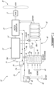
- Fig. 1 illustrates an example of a power plant 10 suitable for use on a hybrid electric aircraft.
- the power plant 10 can adopt various configurations.
- the power plant 10 could be configured as a turboprop engine for driving a propeller 18.
- it can be configured as a turboshaft engine for driving a helicopter rotor or any other load to be driven.
- the hybrid electric power plant 10 could also be used in an auxiliary power unit (APU) installation. Other applications are contemplated as well.
- APU auxiliary power unit
- the power plant 10 generally comprises a fossil-fuel powered engine 12 and an electric motor-generator 14 and a battery pack 16 electrically connected to the motor-generator 14.
- the motor-generator 14 can consist of two distinct motor and generator machines or it can be integrated into one unit.
- the engine 12 can be drivingly connected to the electric motor-generator 14 via output shaft 15'.
- the electric motor-generator 14 is, in turn, drivingly connected to a load (propeller 18 in the illustrated example) via a reductions gearbox (RGB) 17.
- the fossil-fuel powered engine 12 and the motor-generator 14 could be both connected to the RGB 17 to drive the load. Such an arrangement is referred to as a parallel hybrid system.
- the engine 12 could only be used to drive the motor-generator 14 when used in a generator mode for charging the batteries of the battery pack 16, and the load could only be driven by the electric motor 14 via the RGB 17.
- This arrangement can be referred to as a series hybrid system.
- the engine 12 may be provided in the form of a conventional internal combustion engine (e.g. a piston or rotary engine) or in the form of a compound cycle engine such as described in Lents et al.'s US patent No. 7,753,036 issued July 13, 2010 or as described in Julien et al.'s US patent No. 7,775,044 issued August 17, 2010 , or as described in Thomassin et al.'s U.S. patent publication No. 2015/0275749 published October 1, 2015 , or as described in Bolduc et al.'s U.S. patent publication No. 2015/0275756 published October 1, 2015 .
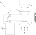
- Fig. 2 illustrates an example of a compound cycle engine 12' suitable for use as engine 12 in Fig. 1 .
- the compound cycle engine 12' generally includes a supercharger compressor 20 for compressing the air prior to feeding an engine core 21 including one or more internal combustion engines 23.
- the exhaust from the engine core 21 is fed to one or more turbines 26, 22 of a compounding turbine section having an outlet fluidly connected to an exhaust duct for discharging the hot combustion gases to atmosphere.
- One or more of the turbines 26, 22 is/are configured to compound power with the engine core 21.
- the turbine and engine shafts are coupled through a transmission provided by a gearbox 28.
- the compressor 20 may be driven by the turbines 26, 22 and/or the engine core 21.
- the compressor 20 is driven by the turbines 26, 22, for example by being coupled to the same shaft or being engaged to the turbine shaft through a transmission provided in the gearbox 28.
- the shaft of the compressor 20 is engaged to the output shaft of the engine core 21, either directly or through a transmission.
- the internal combustion engine(s) 23 of the engine core 21 is/are rotary intermittent internal combustion engines, for example Wankel engines; it is however understood that other types of intermittent internal combustion engines or other types of internal combustion engines may alternately be used.
- the exemplary engine 23 comprises a housing 32 defining a rotor cavity having a profile defining two lobes, which is preferably an epitrochoid.
- a rotor 34 is received within the rotor cavity.
- the rotor defines three circumferentially-spaced apex portions 36, and a generally triangular profile with outwardly arched sides.
- the apex portions 36 are in sealing engagement with the inner surface of a peripheral wall 38 of the housing 32 to form and separate three working chambers 40 of variable volume between the rotor 34 and the housing 32.
- the peripheral wall 38 extends between two axially spaced apart end walls 54 to enclose the rotor cavity.
- the rotor 34 is engaged to an eccentric portion 42 of an output shaft 15 to perform orbital revolutions within the rotor cavity.
- the output shaft 15 performs three rotations for each orbital revolution of the rotor 34.
- the geometrical axis 44 of the rotor 34 is offset from and parallel to the axis 46 of the housing 32.
- each chamber 40 varies in volume and moves around the rotor cavity to undergo the four phases of intake, compression, expansion and exhaust.
- An intake port 48 is provided through the peripheral wall 38 for admitting compressed air into one of the working chambers 40.
- An exhaust port 50 is also provided through the peripheral wall 38 for discharge of the exhaust gases from the working chambers 40.
- Passages 52 for a spark plug, glow plug or other ignition mechanism, as well as for one or more fuel injectors of a fuel injection system are also provided through the peripheral wall 38.
- the intake port 48, the exhaust port 50 and/or the passages 52 may be provided through the end or side wall 54 of the housing.
- a sub-chamber (not shown) may be provided in communication with the chambers 40, for pilot or pre injection of fuel for combustion.
- the working chambers 40 are sealed by spring-loaded peripheral or apex seals 56 extending from the rotor 34 to engage the inner surface of the peripheral wall 38, and spring-loaded face or gas seals 58 and end or corner seals 60 extending from the rotor 34 to engage the inner surface of the end walls 54.
- the rotor 34 also includes at least one spring-loaded oil seal ring 62 biased against the inner surface of the end wall 54 around the bearing for the rotor 34 on the shaft eccentric portion 42.
- the fuel injector(s) of the engine 23 which in a particular embodiment are common rail fuel injectors, communicate with a source of Heavy fuel (e.g. diesel, kerosene (jet fuel), equivalent biofuel), and deliver the heavy fuel into the engine 23 such that the combustion chamber is stratified with a rich fuel-air mixture near the ignition source and a leaner mixture elsewhere.
- a source of Heavy fuel e.g. diesel, kerosene (jet fuel), equivalent biofuel
- the power plant 10 also comprises a lubricant system 70 to provide lubricant to engine 12 and the electric motor-generator 14.
- the lubricant system generally comprises a tank 72 containing a predetermined volume of lubricant (e.g. oil), a lubricant circuit 74 fluidly connecting the tank 72 to engine 12 and the motor-generator 14, and a pump unit 76, which may comprise one or more pumps, for drawing lubricant from the tank 72 and moving the lubricant in a closed loop cycle through the lubricant circuit 74.
- the pump unit 72 can comprise a feed pump mounted in a feed line 74a of the oil circuit 74 between the tank 72 and the engine 12 and the motor-generator 14.
- the feed line 74a of the lubricant circuit 74 can have first and second branches 74a' and 74a" respectively fluidly connected to the engine 12 and the motor-generator 14.
- the feed pump 76 can be disposed upstream of the first and second branches 74a' and 74a".
- a three-way valve 78 or the like may be provided in a return line 74b of the lubricant circuit 74 downstream of the engine 12 and the motor-generator 14 to selectively cause the lubricant coming from the engine 12 and the motor-generator 14 to flow through a heat exchanger 80 before being returned into the tank 72 or to bypass the heat exchanger 80 and direct the lubricant directly back into the tank 72.
- the heat exchanger 80 is an air-liquid heat exchanger.
- a liquid-to-liquid heat exchanger could be used to dissipate the heat picked up by the lubricant as it is circulated through the engine 12 and the motor-generator 14.
- a blower 82 or other air flow inducing devices may be provided to generate a flow of cooling air through the heat exchanger 80 to cool the lubricant.
- the blower 82 may be disposed to draw outside air through an air duct in fluid communication with the heat exchanger 80.
- An electric heater 84 may be provided in the tank 72.
- the battery pack 16 may be electrically connected to the heater 84 to provide electric power to the heater 84 via an electric circuit. Accordingly, on cold days, before the engine 12 is started, the battery pack 16 can be used to electrically heat the lubricant in the tank 72 to reduce oil viscosity and, thus, facilitate starting and reduce the engine starter size.
- a switch 86 may be provided in the electric circuit to selectively electrically power the heater 84.
Landscapes
- Engineering & Computer Science (AREA)
- Chemical & Material Sciences (AREA)
- Mechanical Engineering (AREA)
- Manufacturing & Machinery (AREA)
- Chemical Kinetics & Catalysis (AREA)
- Electrochemistry (AREA)
- General Chemical & Material Sciences (AREA)
- Aviation & Aerospace Engineering (AREA)
- General Engineering & Computer Science (AREA)
- Combustion & Propulsion (AREA)
- Life Sciences & Earth Sciences (AREA)
- Sustainable Development (AREA)
- Sustainable Energy (AREA)
- Power Engineering (AREA)
- Transportation (AREA)
- Hybrid Electric Vehicles (AREA)
- Lubrication Of Internal Combustion Engines (AREA)
Description
- The application relates generally to hybrid electric power plants for aircraft applications and, more particularly, to a method and system for warming batteries in such power plants.
- Temperature plays an important role in the performance of batteries. Batteries are a function of chemical reactions. In cold weather, the chemicals cannot react as fast as in warm weather. A cold battery will, thus, not have the same power as a warm one. In order to provide sufficient electrical power in all weather conditions, it is thus sometimes necessary to increase the number of batteries or use bigger batteries. However, this results in weight increase, which makes hybrid electric power plants less attractive for aircraft applications.
-
US 2014/373533 A1 discloses a prior art energy recovery and cooling system for a hybrid machine powertrain. - In one aspect according to the invention, there is provided a method of operating a hybrid electric power plant as recited in claim 1.
- In another aspect according to the invention, there is also provided a hybrid electric power plant as recited in
claim 10. - Reference is now made to the accompanying figures in which:
-
Fig. 1 is a schematic view of a power plant suitable for use on a hybrid electric aircraft; -
Fig. 2 is a schematic view of a compound cycle engine suitable for use in the power plant shown inFig. 1 , -
Fig. 3 is a schematic cross-sectional view of a rotary engine suitable for use in the compound cycle engine shown inFig. 2 ; and -
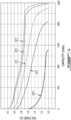
Fig. 4 shows typical characteristics of a Lithium-ion battery as a function of the ambient temperature. -
Fig. 1 illustrates an example of apower plant 10 suitable for use on a hybrid electric aircraft. Thepower plant 10 can adopt various configurations. For instance, thepower plant 10 could be configured as a turboprop engine for driving apropeller 18. According to another example, it can be configured as a turboshaft engine for driving a helicopter rotor or any other load to be driven. The hybridelectric power plant 10 could also be used in an auxiliary power unit (APU) installation. Other applications are contemplated as well. - According to a particular embodiment, the
power plant 10 generally comprises a fossil-fuel poweredengine 12 and an electric motor-generator 14 and abattery pack 16 electrically connected to the motor-generator 14. The motor-generator 14 can consist of two distinct motor and generator machines or it can be integrated into one unit. Theengine 12 can be drivingly connected to the electric motor-generator 14 via output shaft 15'. The electric motor-generator 14 is, in turn, drivingly connected to a load (propeller 18 in the illustrated example) via a reductions gearbox (RGB) 17. According to one possible arrangement, the fossil-fuel poweredengine 12 and the motor-generator 14 could be both connected to theRGB 17 to drive the load. Such an arrangement is referred to as a parallel hybrid system. According to another possible arrangement, theengine 12 could only be used to drive the motor-generator 14 when used in a generator mode for charging the batteries of thebattery pack 16, and the load could only be driven by theelectric motor 14 via theRGB 17. This arrangement can be referred to as a series hybrid system. - The
engine 12 may be provided in the form of a conventional internal combustion engine (e.g. a piston or rotary engine) or in the form of a compound cycle engine such as described inLents et al.'s US patent No. 7,753,036 issued July 13, 2010 or as described inJulien et al.'s US patent No. 7,775,044 issued August 17, 2010 , or as described inThomassin et al.'s U.S. patent publication No. 2015/0275749 published October 1, 2015 , or as described inBolduc et al.'s U.S. patent publication No. 2015/0275756 published October 1, 2015 . -
Fig. 2 illustrates an example of a compound cycle engine 12' suitable for use asengine 12 inFig. 1 . The compound cycle engine 12' generally includes asupercharger compressor 20 for compressing the air prior to feeding an engine core 21 including one or moreinternal combustion engines 23. The exhaust from the engine core 21 is fed to one ormore turbines turbines gearbox 28. Thecompressor 20 may be driven by theturbines compressor 20 is driven by theturbines gearbox 28. In another particular embodiment, the shaft of thecompressor 20 is engaged to the output shaft of the engine core 21, either directly or through a transmission. - In a particular example, the internal combustion engine(s) 23 of the engine core 21 is/are rotary intermittent internal combustion engines, for example Wankel engines; it is however understood that other types of intermittent internal combustion engines or other types of internal combustion engines may alternately be used.
- As shown in
Fig. 3 , theexemplary engine 23 comprises ahousing 32 defining a rotor cavity having a profile defining two lobes, which is preferably an epitrochoid. Arotor 34 is received within the rotor cavity. The rotor defines three circumferentially-spacedapex portions 36, and a generally triangular profile with outwardly arched sides. Theapex portions 36 are in sealing engagement with the inner surface of aperipheral wall 38 of thehousing 32 to form and separate threeworking chambers 40 of variable volume between therotor 34 and thehousing 32. Theperipheral wall 38 extends between two axially spaced apartend walls 54 to enclose the rotor cavity. - The
rotor 34 is engaged to aneccentric portion 42 of anoutput shaft 15 to perform orbital revolutions within the rotor cavity. Theoutput shaft 15 performs three rotations for each orbital revolution of therotor 34. Thegeometrical axis 44 of therotor 34 is offset from and parallel to theaxis 46 of thehousing 32. During each rotation of therotor 34, eachchamber 40 varies in volume and moves around the rotor cavity to undergo the four phases of intake, compression, expansion and exhaust. - An
intake port 48 is provided through theperipheral wall 38 for admitting compressed air into one of theworking chambers 40. Anexhaust port 50 is also provided through theperipheral wall 38 for discharge of the exhaust gases from theworking chambers 40.Passages 52 for a spark plug, glow plug or other ignition mechanism, as well as for one or more fuel injectors of a fuel injection system (not shown) are also provided through theperipheral wall 38. Alternately, theintake port 48, theexhaust port 50 and/or thepassages 52 may be provided through the end orside wall 54 of the housing. A sub-chamber (not shown) may be provided in communication with thechambers 40, for pilot or pre injection of fuel for combustion. - For efficient operation the
working chambers 40 are sealed by spring-loaded peripheral orapex seals 56 extending from therotor 34 to engage the inner surface of theperipheral wall 38, and spring-loaded face orgas seals 58 and end orcorner seals 60 extending from therotor 34 to engage the inner surface of theend walls 54. Therotor 34 also includes at least one spring-loadedoil seal ring 62 biased against the inner surface of theend wall 54 around the bearing for therotor 34 on the shafteccentric portion 42. - The fuel injector(s) of the
engine 23, which in a particular embodiment are common rail fuel injectors, communicate with a source of Heavy fuel (e.g. diesel, kerosene (jet fuel), equivalent biofuel), and deliver the heavy fuel into theengine 23 such that the combustion chamber is stratified with a rich fuel-air mixture near the ignition source and a leaner mixture elsewhere. - As shown in
Fig. 1 , thepower plant 10 also comprises alubricant system 70 to provide lubricant toengine 12 and the electric motor-generator 14. The lubricant system generally comprises atank 72 containing a predetermined volume of lubricant (e.g. oil), alubricant circuit 74 fluidly connecting thetank 72 toengine 12 and the motor-generator 14, and apump unit 76, which may comprise one or more pumps, for drawing lubricant from thetank 72 and moving the lubricant in a closed loop cycle through thelubricant circuit 74. For instance, thepump unit 72 can comprise a feed pump mounted in afeed line 74a of theoil circuit 74 between thetank 72 and theengine 12 and the motor-generator 14. Thefeed line 74a of thelubricant circuit 74 can have first andsecond branches 74a' and 74a" respectively fluidly connected to theengine 12 and the motor-generator 14. Thefeed pump 76 can be disposed upstream of the first andsecond branches 74a' and 74a". A three-way valve 78 or the like may be provided in areturn line 74b of thelubricant circuit 74 downstream of theengine 12 and the motor-generator 14 to selectively cause the lubricant coming from theengine 12 and the motor-generator 14 to flow through aheat exchanger 80 before being returned into thetank 72 or to bypass theheat exchanger 80 and direct the lubricant directly back into thetank 72. According to the illustrated example, theheat exchanger 80 is an air-liquid heat exchanger. However, it is understood that other types of heat exchanger could be used. For instance, a liquid-to-liquid heat exchanger could be used to dissipate the heat picked up by the lubricant as it is circulated through theengine 12 and the motor-generator 14. In the case of an air-liquid heat exchanger, ablower 82 or other air flow inducing devices may be provided to generate a flow of cooling air through theheat exchanger 80 to cool the lubricant. According to a particular embodiment, theblower 82 may be disposed to draw outside air through an air duct in fluid communication with theheat exchanger 80. - An
electric heater 84 may be provided in thetank 72. Thebattery pack 16 may be electrically connected to theheater 84 to provide electric power to theheater 84 via an electric circuit. Accordingly, on cold days, before theengine 12 is started, thebattery pack 16 can be used to electrically heat the lubricant in thetank 72 to reduce oil viscosity and, thus, facilitate starting and reduce the engine starter size. Aswitch 86 may be provided in the electric circuit to selectively electrically power theheater 84. - Still referring to
Fig. 1 , it can be appreciated that thepower plant 10 further comprises acoolant circuit 90. In a particular embodiment, thecoolant circuit 90 can be provided in the form of a liquid coolant circuit in heat exchange relationship with theengine housing 32 in order to pick up waste heat from the internal combustion engine 23 (about 70% of the output power of the engine). As shown inFig. 3 , theliquid coolant circuit 90 may includecoolant passages 64 extending through the walls of theengine housing 32. Apumping unit 92, which may include one pump or more, is strategically positioned in thecoolant circuit 90 to move the liquid coolant in a continuous closed-loop cycle through thecoolant circuit 90. In a particular embodiment, the engine coolant may be for example water, or water mixed with anti-freeze liquid(s), such as ethylene glycol. The same coolant circuit or a separate/distinct cooling circuit may be used to cool down the motor-generator 14. - The
battery pack 16 can include various energy storage devices. For instance, thebattery pack 16 may comprise any suitable combination of high power density batteries. For instance, thebattery pack 16 may comprise one or more Lithium-ion or lead acid batteries. As mentioned hereinbefore, temperature plays an important role in the performance of electrolytic processes and, thus, on the performance of batteries.Fig. 4 shows typical characteristics of a Lithium-ion battery as a function of ambient temperature. In cold climates, like at -20 Celsius, the battery capacity and power reduces by about 50%. Therefore, on cold days, it is desirable to warm thebattery pack 16 to improve the efficiency thereof. As theengine 12 comprises an internal combustion engine, it generates significant waste heat. It is herein proposed to use at least part of this waste heat to warm the batteries on cold days and, thus, preserve their power. - For instance, the waste heat picked up by the engine coolant and/or the engine lubricant while circulated through the
internal combustion engine 23 could be used to preheat thebattery pack 16 whenever the efficiency of the batteries is likely to be diminished by the environment temperature. For instance, as illustrated inFig. 1 , thecoolant circuit 90 could be coiled around or otherwise connected in heat exchange relationship with thebattery pack 16. Avalve 94 can be provided in thecoolant circuit 90 downstream of theinternal combustion engine 23 to control the flow of warm coolant to thebattery pack 16. Thevalve 94 could, for instance, be provided in the form of a three-way valve having one of its two outlets connected to abypass branch 90a of thecoolant circuit 90 for the warm coolant to selectively bypass thebattery pack 16 when the same is within an appropriate range of operating temperatures. Still referring toFig. 1 , it can be appreciated that aheat exchanger 96 is provided in thecoolant circuit 90 downstream of thebattery pack 16 to further cool the coolant prior to being redirected into theinternal combustion engine 23. Theheat exchanger 96 can be integrated to thelubricant heat exchanger 80 or separate. In the embodiment illustrated inFig. 1 , theheat exchanger 96 is an air-liquid heat exchanger and the cooling air circulated through theheat exchanger 96 is drawn by thesame blower 82 as the one used to generate a flow of air through thelubricant heat exchanger 80. Accordingly, bothheat exchangers - In cold climates, the
power plant 10 can be operated to first warm the lubricant withelectric heater 84. Once the lubricant has the desired viscosity, theinternal combustion engine 23 can be started and allowed to warm up. Once theengine 23 is warmed up, the temperature of the liquid coolant will typically range from about 150 degrees Fahrenheit (66°C) to about 250 degrees Fahrenheit (121°C). Thevalve 94 can be operated to direct the warm engine coolant to thebattery pack 16 to transfer waste heat picked up from theinternal combustion engine 23 to the batteries of thebattery pack 16, thereby increasing the capacity and power output of the batteries for take-off in cold environments. While the batteries are being warmed up, theinternal combustion engine 23 can be operated to drive the motor-generator 14 to generate electrical power for charging the batteries. Thereafter, the warmed and charged batteries can be used to provide electric power to the electric-motor generator 14 to drive thepropeller 18 alone or in combination with the compound cycle engine. - As mentioned hereinbefore, the
warm lubricant circuit 74 can also be used to warm the batteries. This can be done to supplement the heat carried to the batteries by the engine coolant or in place thereof. The person skilled in the art will appreciate that various arrangements are possible to transfer the heat absorbed by the lubricant to thebattery pack 16. - Conventional gas turbine engines have no coolant and very little heat available in the oil cooler, and nearly all the rejected heat is in the exhaust. Using the exhaust gas to warm the battery is more complicated as the exhaust is very hot (over 1000 degrees Fahrenheit (538°C)) and ends up in a heavier system. Accordingly, while the fossil-fuel powered
engine 12 could be provided in the form of a conventional gas turbine engine, a person skilled in the art will appreciate that the compound cycle engine embodiment shown inFig. 2 offers more synergy for hybrid electric aircraft applications than conventional gas turbine engines. - On hot days or whenever the batteries need to be cooled, the
blower 82 of the engine coolant and lubricant systems can be used to direct cooling air over thebattery pack 16. Also, a separate cooling circuit could be provided to remove heat from thebattery pack 16.
Claims (12)
- A method of operating a hybrid electric power plant (10), the hybrid electric power plant (10) having an internal combustion engine (12; 23), an electric motor (14) and a battery pack (16), the method comprising: a) absorbing heat generated by the internal combustion engine (12; 23), and b) using the heat absorbed from the internal combustion engine (12; 23) to warm the battery pack (16),wherein a) comprises circulating a coolant in heat exchange relationship with the internal combustion engine (12; 23), and b) comprises circulating the coolant heated by the internal combustion engine (12; 23) in heat exchange relationship with the battery pack (16),wherein a) further comprises circulating a liquid coolant through a housing (38) of the internal combustion engine (12; 23), and circulating the coolant heated by the internal combustion engine (12; 23) in heat exchange relationship with the battery pack (16) comprises circulating the liquid coolant around the battery pack (16),characterized in thatb) further comprises controlling the flow of coolant to the battery pack (16) as a function of an environmental temperature.
- The method of claim 1, comprising causing at least part of the coolant heated by the internal combustion engine (12; 23) to bypass the battery pack (16).
- The method of claim 1 or 2, comprising operating a valve (94) in a coolant circuit (90) between the internal combustion engine (12; 23) and the battery pack (16).
- The method of any preceding claim, further comprising circulating the coolant through a heat exchanger (96) to further cool the coolant downstream of the battery pack (16) before re-circulating the coolant through the internal combustion engine (12; 23).
- The method of claim 4, comprising directing a flow of cooling air through the heat exchanger (96) to cool the coolant, and using said cooling air to cool the battery pack (16) when it is determined that the battery pack (16) needs to be cooled.
- The method of any preceding claim, wherein b) comprises: circulating a lubricant through a lubricant circuit (74) extending through the internal combustion engine (12; 23), and using heat absorbed from the internal combustion engine (12; 23) by the lubricant to warm the battery pack (16).
- The method of any preceding claim, wherein the hybrid electric power plant (10) further comprises a compressor (20) and a turbine (22; 26), and the method further comprises turbocompounding the internal combustion engine (12; 23).
- The method of any preceding claim, comprising using the battery pack (16) to heat a lubricant of the internal combustion engine (12; 23) prior to starting the internal combustion engine (12; 23), and after b) using the battery pack (16) to provide electrical power to the electric motor (14).
- The method of claim 1, wherein the hybrid electric power plant (10) is an aircraft power plant and the method comprises: starting the internal combustion engine (12; 23), circulating a coolant in heat exchange relationship with the internal combustion engine (12; 23) to absorb waste heat generated by the internal combustion engine (12; 23), circulating the coolant heated by internal combustion engine (12; 23) in heat exchange relationship with the battery pack (16), the coolant transferring heat to the battery pack (16) to warm the battery pack (16), and then using the battery pack (16) to power the electric motor (14).
- A hybrid electric power plant (10) comprising:a compressor (20);an internal combustion engine (12; 23) having an inlet (48) fluidly connected to an outlet of the compressor (20), the internal combustion engine (12; 23) having a housing (38) and a coolant circuit (90) having liquid coolant, wherein the internal combustion engine (12; 23) is configured to heat the liquid coolant;a turbine (26) having an inlet fluidly connected to an outlet (50) of the internal combustion engine (12; 23);an electric motor (14);a battery pack (16) configured to provide electric power to the electric motor (14), the battery pack (16) in heat exchange relationship with the coolant circuit (90) of the internal combustion engine (12; 23), wherein the coolant circuit (90) is configured such that the liquid coolant is circulated around the battery pack (16); andcharacterized by a controller, which is configured to control the flow of liquid coolant to the battery pack (16) as a function of an environmental temperature.
- The hybrid electric power plant (10) of claim 10, wherein a valve (94) is positioned in the coolant circuit (90) between the internal combustion engine (12; 23) and the battery pack (16), the valve (94) having an outlet connected to a bypass line (90a) to selectively divert the coolant to bypass the battery pack (16).
- The hybrid electric power plant (10) of claim 10 or 11, wherein the internal combustion engine (12; 23) has a lubricant circuit (74), and the lubricant circuit (74) is in heat exchange relationship with the battery pack (16).
Applications Claiming Priority (1)
| Application Number | Priority Date | Filing Date | Title |
|---|---|---|---|
| US16/171,473 US10752129B2 (en) | 2018-10-26 | 2018-10-26 | Battery heating in hybrid electric power plant |
Publications (2)
| Publication Number | Publication Date |
|---|---|
| EP3643889A1 EP3643889A1 (en) | 2020-04-29 |
| EP3643889B1 true EP3643889B1 (en) | 2025-03-19 |
Family
ID=68387170
Family Applications (1)
| Application Number | Title | Priority Date | Filing Date |
|---|---|---|---|
| EP19205741.2A Active EP3643889B1 (en) | 2018-10-26 | 2019-10-28 | Battery heating in hybrid electric power plant |
Country Status (5)
| Country | Link |
|---|---|
| US (1) | US10752129B2 (en) |
| EP (1) | EP3643889B1 (en) |
| CN (1) | CN111106414A (en) |
| CA (1) | CA3058174A1 (en) |
| PL (1) | PL3643889T3 (en) |
Families Citing this family (26)
| Publication number | Priority date | Publication date | Assignee | Title |
|---|---|---|---|---|
| EP3719919A1 (en) * | 2019-03-20 | 2020-10-07 | Hamilton Sundstrand Corporation | Thermal regulation of batteries |
| US11649064B2 (en) * | 2019-08-02 | 2023-05-16 | Hamilton Sundstrand Corporation | Integrated motor drive cooling |
| US12365474B2 (en) * | 2019-08-23 | 2025-07-22 | Verdego Aero, Inc. | Battery preheating systems and methods in an aircraft hybrid electric powertrain |
| CN111959347B (en) * | 2020-08-13 | 2022-08-26 | 宜宾凯翼汽车有限公司 | Control method of parking heater for battery pack |
| JP2022053627A (en) * | 2020-09-25 | 2022-04-06 | 本田技研工業株式会社 | Propulsion system |
| JP7210527B2 (en) * | 2020-12-14 | 2023-01-23 | Hapsモバイル株式会社 | flying object |
| JP7210526B2 (en) | 2020-12-14 | 2023-01-23 | Hapsモバイル株式会社 | flying object |
| CN112744128B (en) * | 2021-01-20 | 2022-05-17 | 江苏大学 | Waste heat management device and management method of oil-electricity hybrid power system |
| BR112023016761A2 (en) * | 2021-03-19 | 2023-10-31 | Verdego Aero Inc | SIMULTANEOUS AIR COOLING OF MULTIPLE ELEMENTS OF A HYBRID HIGH POWER ENGINE |
| EP4067632B1 (en) * | 2021-03-31 | 2024-09-18 | Volvo Truck Corporation | Method of managing the oil temperature of a transmission of a motor vehicle |
| CN114810453A (en) * | 2021-06-09 | 2022-07-29 | 长城汽车股份有限公司 | Low-temperature cold starting method and system for P2-configuration hybrid vehicle and vehicle |
| CN113320378B (en) * | 2021-06-29 | 2022-08-09 | 重庆金康赛力斯新能源汽车设计院有限公司 | Efficient integrated engine thermal management system and vehicle |
| CN113320377B (en) * | 2021-06-29 | 2022-11-25 | 重庆金康赛力斯新能源汽车设计院有限公司 | Whole vehicle thermal management system capable of recycling energy and vehicle |
| JP2023031159A (en) * | 2021-08-24 | 2023-03-08 | トヨタ自動車株式会社 | Vehicular lubrication system and control device for the same |
| CN113580905B (en) * | 2021-08-31 | 2023-05-26 | 奇瑞汽车股份有限公司 | Thermal management system of plug-in hybrid electric vehicle and plug-in hybrid electric vehicle |
| US11691742B1 (en) * | 2022-02-04 | 2023-07-04 | Pratt & Whitney Canada Corp | Containment zone for an electric machine in a hybrid powerplant for an aircraft |
| US20230352760A1 (en) * | 2022-04-29 | 2023-11-02 | Pratt & Whitney Canada Corp. | Electrical heating system for hybrid powerplant electrical power source |
| US12012893B2 (en) * | 2022-11-14 | 2024-06-18 | Pratt & Whitney Canada Corp. | Lubricant reservoir with integrated heat exchanger |
| CN116022382B (en) * | 2023-03-30 | 2023-07-04 | 西安麦莎科技有限公司 | Outdoor unmanned aerial vehicle and charging device thereof |
| CN116605096B (en) * | 2023-06-02 | 2025-09-09 | 中国第一汽车股份有限公司 | Thermal management system, control method, vehicle, and storage medium |
| US12503246B2 (en) * | 2023-06-09 | 2025-12-23 | Pratt & Whitney Canada Corp. | Electric motor propulsion system for an aircraft |
| US20240425188A1 (en) * | 2023-06-26 | 2024-12-26 | Pratt & Whitney Canada Corp. | Testing secondary power system of aircraft powerplant |
| US12291347B2 (en) | 2023-07-31 | 2025-05-06 | Pratt & Whitney Canada Corp. | Containment zone for an electric machine in a hybrid powerplant for an aircraft |
| SE2450100A1 (en) * | 2024-01-31 | 2025-08-01 | Heart Aerospace AB | Aerospace thermal management system |
| US12371182B1 (en) | 2024-11-01 | 2025-07-29 | General Electric Company | Component heating in hybrid electric propulsion systems |
| CN119582297B (en) * | 2024-12-14 | 2025-08-01 | 国能浙江宁海发电有限公司 | Thermal power coupling battery data monitoring and safe operation optimizing method |
Family Cites Families (34)
| Publication number | Priority date | Publication date | Assignee | Title |
|---|---|---|---|---|
| GB410169A (en) * | 1932-11-10 | 1934-05-10 | Gerard Anstis Wadham | An improved means for bringing internal combustion engines to and maintaining at a temperature to ensure efficient operation and easy starting |
| FR1511898A (en) * | 1967-02-17 | 1968-02-02 | Sachsenring Automobilwerke | Lubricating device for internal combustion engine |
| US7147071B2 (en) * | 2004-02-04 | 2006-12-12 | Battelle Energy Alliance, Llc | Thermal management systems and methods |
| JP2000297622A (en) * | 1999-04-16 | 2000-10-24 | Nippon Soken Inc | Oil temperature control device for internal combustion engine |
| US6672415B1 (en) * | 1999-05-26 | 2004-01-06 | Toyota Jidosha Kabushiki Kaisha | Moving object with fuel cells incorporated therein and method of controlling the same |
| US6394210B2 (en) * | 1999-06-07 | 2002-05-28 | Mitsubishi Heavy Industries, Ltd. | Temperature controller for vehicular battery |
| US6865901B2 (en) * | 2002-05-29 | 2005-03-15 | Webasto Thermosysteme International Gmbh | System with an internal combustion engine, a fuel cell and a climate control unit for heating and/or cooling the interior of a motor vehicle and process for the operation thereof |
| EP1611331B1 (en) | 2003-02-24 | 2010-09-01 | Pratt & Whitney Canada Corp. | Low volumetric compression ratio integrated turbo-compound rotary engine |
| US8141360B1 (en) | 2005-10-18 | 2012-03-27 | Florida Turbine Technologies, Inc. | Hybrid gas turbine and internal combustion engine |
| DE102007004979A1 (en) * | 2007-02-01 | 2008-08-07 | Daimler Ag | Traction battery cooling and/or tempering device for use in motor vehicle i.e. hybrid vehicle, has battery and cooling circuit thermally coupled with each other by refrigerant circuit to release heat on part of battery with low temperature |
| US7769505B2 (en) * | 2007-05-03 | 2010-08-03 | Gm Global Technology Operations, Inc. | Method of operating a plug-in hybrid electric vehicle |
| US7753036B2 (en) | 2007-07-02 | 2010-07-13 | United Technologies Corporation | Compound cycle rotary engine |
| US8263279B2 (en) * | 2008-02-20 | 2012-09-11 | GM Global Technology Operations LLC | Apparatus for optimized cooling of a drive unit and a fuel cell in a fuel cell vehicle |
| DE102009028326A1 (en) * | 2009-08-07 | 2011-02-10 | Robert Bosch Gmbh | Method and device for heating engine and transmission oil of a hybrid vehicle |
| US20120168111A1 (en) * | 2009-09-25 | 2012-07-05 | Dow Global Technologies Inc. | Heat transfer system utilizing thermal energy storage materials |
| DE102009043316A1 (en) * | 2009-09-28 | 2011-03-31 | Valeo Klimasysteme Gmbh | Method for controlling the interior temperature of an electrically operated vehicle and air conditioning system |
| JP5437906B2 (en) * | 2010-05-14 | 2014-03-12 | 株式会社豊田中央研究所 | Battery heating device |
| WO2013115251A1 (en) * | 2012-02-03 | 2013-08-08 | 住友電気工業株式会社 | Battery device and battery heating system and vehicle |
| JP2013217631A (en) * | 2012-03-14 | 2013-10-24 | Denso Corp | Refrigeration cycle device |
| JP6201434B2 (en) * | 2012-07-18 | 2017-09-27 | 株式会社デンソー | Refrigeration cycle equipment |
| US9926843B2 (en) | 2012-07-20 | 2018-03-27 | Pratt & Whitney Canada Corp. | Compound cycle engine |
| US10107195B2 (en) | 2012-07-20 | 2018-10-23 | Pratt & Whitney Canada Corp. | Compound cycle engine |
| US20160229282A1 (en) * | 2013-02-09 | 2016-08-11 | Quantumscape Corporation | Thermal management system for vehicles with an electric powertrain |
| US9181866B2 (en) | 2013-06-21 | 2015-11-10 | Caterpillar Inc. | Energy recovery and cooling system for hybrid machine powertrain |
| JP6233009B2 (en) * | 2013-12-26 | 2017-11-22 | 株式会社デンソー | Air conditioner for vehicles |
| JP6252186B2 (en) * | 2014-01-15 | 2017-12-27 | 株式会社デンソー | Thermal management system for vehicles |
| US9914338B2 (en) * | 2014-03-06 | 2018-03-13 | GM Global Technology Operations LLC | Thermal management system for a vehicle |
| JP6496163B2 (en) * | 2015-03-03 | 2019-04-03 | 日立建機株式会社 | Hybrid construction machine |
| GB2539299B (en) | 2015-06-12 | 2017-11-08 | Rolls Royce Corp | Battery arrangements for gas turbine engines |
| US9786966B2 (en) | 2015-09-11 | 2017-10-10 | Ford Global Technologies, Llc | Cold plate assembly for electrified vehicle battery packs |
| US10996000B2 (en) * | 2015-11-04 | 2021-05-04 | Toyota Motor Engineering & Manufacturing North America, Inc. | Absorption-based system for automotive waste heat recovery |
| CN205376687U (en) * | 2016-01-19 | 2016-07-06 | 苏州高迈新能源有限公司 | Group battery temperature regulating device for hybrid vehicle |
| CN107256934B (en) * | 2017-05-20 | 2019-11-12 | 沈阳中北真空技术有限公司 | A kind of new energy car battery group management system and control method |
| US10738667B2 (en) * | 2017-11-03 | 2020-08-11 | Dana Heavy Vehicle Systems Group, Llc | Heat transfer system |
-
2018
- 2018-10-26 US US16/171,473 patent/US10752129B2/en active Active
-
2019
- 2019-10-08 CA CA3058174A patent/CA3058174A1/en active Pending
- 2019-10-25 CN CN201911022374.2A patent/CN111106414A/en active Pending
- 2019-10-28 PL PL19205741.2T patent/PL3643889T3/en unknown
- 2019-10-28 EP EP19205741.2A patent/EP3643889B1/en active Active
Also Published As
| Publication number | Publication date |
|---|---|
| CA3058174A1 (en) | 2020-04-26 |
| EP3643889A1 (en) | 2020-04-29 |
| US10752129B2 (en) | 2020-08-25 |
| US20200130534A1 (en) | 2020-04-30 |
| CN111106414A (en) | 2020-05-05 |
| PL3643889T3 (en) | 2025-06-23 |
Similar Documents
| Publication | Publication Date | Title |
|---|---|---|
| EP3643889B1 (en) | Battery heating in hybrid electric power plant | |
| EP3127814B1 (en) | Aircraft heating assembly with liquid cooled internal combustion engine and heating element using waste heat | |
| US11584539B2 (en) | Auxiliary power unit with intercooler | |
| US10724429B2 (en) | Auxiliary power unit with electrically driven compressor | |
| EP3112271B1 (en) | Auxiliary power unit with excess air recovery | |
| EP3647205A1 (en) | Method and system for cooling an auxiliary power unit using aircraft fuel | |
| CN107923312B (en) | Compound engine assembly with bleed air | |
| WO2016205934A1 (en) | Compound engine assembly with direct drive of generator | |
| US10738749B1 (en) | Method of using heat from fuel of common-rail injectors | |
| EP3690212B1 (en) | Engine assembly with heat management system |
Legal Events
| Date | Code | Title | Description |
|---|---|---|---|
| PUAI | Public reference made under article 153(3) epc to a published international application that has entered the european phase |
Free format text: ORIGINAL CODE: 0009012 |
|
| STAA | Information on the status of an ep patent application or granted ep patent |
Free format text: STATUS: THE APPLICATION HAS BEEN PUBLISHED |
|
| AK | Designated contracting states |
Kind code of ref document: A1 Designated state(s): AL AT BE BG CH CY CZ DE DK EE ES FI FR GB GR HR HU IE IS IT LI LT LU LV MC MK MT NL NO PL PT RO RS SE SI SK SM TR |
|
| STAA | Information on the status of an ep patent application or granted ep patent |
Free format text: STATUS: REQUEST FOR EXAMINATION WAS MADE |
|
| 17P | Request for examination filed |
Effective date: 20201029 |
|
| RBV | Designated contracting states (corrected) |
Designated state(s): AL AT BE BG CH CY CZ DE DK EE ES FI FR GB GR HR HU IE IS IT LI LT LU LV MC MK MT NL NO PL PT RO RS SE SI SK SM TR |
|
| STAA | Information on the status of an ep patent application or granted ep patent |
Free format text: STATUS: EXAMINATION IS IN PROGRESS |
|
| 17Q | First examination report despatched |
Effective date: 20240517 |
|
| GRAP | Despatch of communication of intention to grant a patent |
Free format text: ORIGINAL CODE: EPIDOSNIGR1 |
|
| STAA | Information on the status of an ep patent application or granted ep patent |
Free format text: STATUS: GRANT OF PATENT IS INTENDED |
|
| INTG | Intention to grant announced |
Effective date: 20241008 |
|
| GRAS | Grant fee paid |
Free format text: ORIGINAL CODE: EPIDOSNIGR3 |
|
| GRAA | (expected) grant |
Free format text: ORIGINAL CODE: 0009210 |
|
| STAA | Information on the status of an ep patent application or granted ep patent |
Free format text: STATUS: THE PATENT HAS BEEN GRANTED |
|
| AK | Designated contracting states |
Kind code of ref document: B1 Designated state(s): AL AT BE BG CH CY CZ DE DK EE ES FI FR GB GR HR HU IE IS IT LI LT LU LV MC MK MT NL NO PL PT RO RS SE SI SK SM TR |
|
| REG | Reference to a national code |
Ref country code: GB Ref legal event code: FG4D |
|
| REG | Reference to a national code |
Ref country code: CH Ref legal event code: EP |
|
| REG | Reference to a national code |
Ref country code: DE Ref legal event code: R096 Ref document number: 602019067416 Country of ref document: DE |
|
| REG | Reference to a national code |
Ref country code: IE Ref legal event code: FG4D |
|
| PG25 | Lapsed in a contracting state [announced via postgrant information from national office to epo] |
Ref country code: RS Free format text: LAPSE BECAUSE OF FAILURE TO SUBMIT A TRANSLATION OF THE DESCRIPTION OR TO PAY THE FEE WITHIN THE PRESCRIBED TIME-LIMIT Effective date: 20250619 |
|
| PG25 | Lapsed in a contracting state [announced via postgrant information from national office to epo] |
Ref country code: FI Free format text: LAPSE BECAUSE OF FAILURE TO SUBMIT A TRANSLATION OF THE DESCRIPTION OR TO PAY THE FEE WITHIN THE PRESCRIBED TIME-LIMIT Effective date: 20250319 |
|
| REG | Reference to a national code |
Ref country code: LT Ref legal event code: MG9D |
|
| PG25 | Lapsed in a contracting state [announced via postgrant information from national office to epo] |
Ref country code: NO Free format text: LAPSE BECAUSE OF FAILURE TO SUBMIT A TRANSLATION OF THE DESCRIPTION OR TO PAY THE FEE WITHIN THE PRESCRIBED TIME-LIMIT Effective date: 20250619 |
|
| PG25 | Lapsed in a contracting state [announced via postgrant information from national office to epo] |
Ref country code: HR Free format text: LAPSE BECAUSE OF FAILURE TO SUBMIT A TRANSLATION OF THE DESCRIPTION OR TO PAY THE FEE WITHIN THE PRESCRIBED TIME-LIMIT Effective date: 20250319 |
|
| PG25 | Lapsed in a contracting state [announced via postgrant information from national office to epo] |
Ref country code: LV Free format text: LAPSE BECAUSE OF FAILURE TO SUBMIT A TRANSLATION OF THE DESCRIPTION OR TO PAY THE FEE WITHIN THE PRESCRIBED TIME-LIMIT Effective date: 20250319 |
|
| PG25 | Lapsed in a contracting state [announced via postgrant information from national office to epo] |
Ref country code: BG Free format text: LAPSE BECAUSE OF FAILURE TO SUBMIT A TRANSLATION OF THE DESCRIPTION OR TO PAY THE FEE WITHIN THE PRESCRIBED TIME-LIMIT Effective date: 20250319 Ref country code: GR Free format text: LAPSE BECAUSE OF FAILURE TO SUBMIT A TRANSLATION OF THE DESCRIPTION OR TO PAY THE FEE WITHIN THE PRESCRIBED TIME-LIMIT Effective date: 20250620 |
|
| REG | Reference to a national code |
Ref country code: NL Ref legal event code: MP Effective date: 20250319 |
|
| PG25 | Lapsed in a contracting state [announced via postgrant information from national office to epo] |
Ref country code: NL Free format text: LAPSE BECAUSE OF FAILURE TO SUBMIT A TRANSLATION OF THE DESCRIPTION OR TO PAY THE FEE WITHIN THE PRESCRIBED TIME-LIMIT Effective date: 20250319 |
|
| PG25 | Lapsed in a contracting state [announced via postgrant information from national office to epo] |
Ref country code: SE Free format text: LAPSE BECAUSE OF FAILURE TO SUBMIT A TRANSLATION OF THE DESCRIPTION OR TO PAY THE FEE WITHIN THE PRESCRIBED TIME-LIMIT Effective date: 20250319 |
|
| PG25 | Lapsed in a contracting state [announced via postgrant information from national office to epo] |
Ref country code: SM Free format text: LAPSE BECAUSE OF FAILURE TO SUBMIT A TRANSLATION OF THE DESCRIPTION OR TO PAY THE FEE WITHIN THE PRESCRIBED TIME-LIMIT Effective date: 20250319 |
|
| PG25 | Lapsed in a contracting state [announced via postgrant information from national office to epo] |
Ref country code: PT Free format text: LAPSE BECAUSE OF FAILURE TO SUBMIT A TRANSLATION OF THE DESCRIPTION OR TO PAY THE FEE WITHIN THE PRESCRIBED TIME-LIMIT Effective date: 20250721 Ref country code: ES Free format text: LAPSE BECAUSE OF FAILURE TO SUBMIT A TRANSLATION OF THE DESCRIPTION OR TO PAY THE FEE WITHIN THE PRESCRIBED TIME-LIMIT Effective date: 20250319 |
|
| PGFP | Annual fee paid to national office [announced via postgrant information from national office to epo] |
Ref country code: PL Payment date: 20250925 Year of fee payment: 7 Ref country code: IT Payment date: 20250923 Year of fee payment: 7 |
|
| PGFP | Annual fee paid to national office [announced via postgrant information from national office to epo] |
Ref country code: GB Payment date: 20250923 Year of fee payment: 7 |
|
| PGFP | Annual fee paid to national office [announced via postgrant information from national office to epo] |
Ref country code: FR Payment date: 20250925 Year of fee payment: 7 |
|
| PG25 | Lapsed in a contracting state [announced via postgrant information from national office to epo] |
Ref country code: EE Free format text: LAPSE BECAUSE OF FAILURE TO SUBMIT A TRANSLATION OF THE DESCRIPTION OR TO PAY THE FEE WITHIN THE PRESCRIBED TIME-LIMIT Effective date: 20250319 |
|
| PGFP | Annual fee paid to national office [announced via postgrant information from national office to epo] |
Ref country code: CZ Payment date: 20250929 Year of fee payment: 7 |
|
| PG25 | Lapsed in a contracting state [announced via postgrant information from national office to epo] |
Ref country code: RO Free format text: LAPSE BECAUSE OF FAILURE TO SUBMIT A TRANSLATION OF THE DESCRIPTION OR TO PAY THE FEE WITHIN THE PRESCRIBED TIME-LIMIT Effective date: 20250319 |
|
| PG25 | Lapsed in a contracting state [announced via postgrant information from national office to epo] |
Ref country code: SK Free format text: LAPSE BECAUSE OF FAILURE TO SUBMIT A TRANSLATION OF THE DESCRIPTION OR TO PAY THE FEE WITHIN THE PRESCRIBED TIME-LIMIT Effective date: 20250319 |
|
| PG25 | Lapsed in a contracting state [announced via postgrant information from national office to epo] |
Ref country code: IS Free format text: LAPSE BECAUSE OF FAILURE TO SUBMIT A TRANSLATION OF THE DESCRIPTION OR TO PAY THE FEE WITHIN THE PRESCRIBED TIME-LIMIT Effective date: 20250719 |
|
| REG | Reference to a national code |
Ref country code: CH Ref legal event code: U11 Free format text: ST27 STATUS EVENT CODE: U-0-0-U10-U11 (AS PROVIDED BY THE NATIONAL OFFICE) Effective date: 20251101 |
|
| REG | Reference to a national code |
Ref country code: DE Ref legal event code: R097 Ref document number: 602019067416 Country of ref document: DE |
|
| PGFP | Annual fee paid to national office [announced via postgrant information from national office to epo] |
Ref country code: DE Payment date: 20250923 Year of fee payment: 7 |
|
| PG25 | Lapsed in a contracting state [announced via postgrant information from national office to epo] |
Ref country code: DK Free format text: LAPSE BECAUSE OF FAILURE TO SUBMIT A TRANSLATION OF THE DESCRIPTION OR TO PAY THE FEE WITHIN THE PRESCRIBED TIME-LIMIT Effective date: 20250319 |
|
| PGFP | Annual fee paid to national office [announced via postgrant information from national office to epo] |
Ref country code: AT Payment date: 20250926 Year of fee payment: 7 |
|
| PGFP | Annual fee paid to national office [announced via postgrant information from national office to epo] |
Ref country code: CH Payment date: 20251101 Year of fee payment: 7 |
|
| PLBE | No opposition filed within time limit |
Free format text: ORIGINAL CODE: 0009261 |
|
| STAA | Information on the status of an ep patent application or granted ep patent |
Free format text: STATUS: NO OPPOSITION FILED WITHIN TIME LIMIT |
|
| REG | Reference to a national code |
Ref country code: CH Ref legal event code: L10 Free format text: ST27 STATUS EVENT CODE: U-0-0-L10-L00 (AS PROVIDED BY THE NATIONAL OFFICE) Effective date: 20260128 |
|
| 26N | No opposition filed |
Effective date: 20251222 |