EP3643841A1 - Hydraulic fill system - Google Patents
Hydraulic fill system Download PDFInfo
- Publication number
- EP3643841A1 EP3643841A1 EP19204599.5A EP19204599A EP3643841A1 EP 3643841 A1 EP3643841 A1 EP 3643841A1 EP 19204599 A EP19204599 A EP 19204599A EP 3643841 A1 EP3643841 A1 EP 3643841A1
- Authority
- EP
- European Patent Office
- Prior art keywords
- arm
- hydraulic fluid
- hydraulic
- conduit
- couples
- Prior art date
- Legal status (The legal status is an assumption and is not a legal conclusion. Google has not performed a legal analysis and makes no representation as to the accuracy of the status listed.)
- Granted
Links
Images



Classifications
-
- A—HUMAN NECESSITIES
- A01—AGRICULTURE; FORESTRY; ANIMAL HUSBANDRY; HUNTING; TRAPPING; FISHING
- A01B—SOIL WORKING IN AGRICULTURE OR FORESTRY; PARTS, DETAILS, OR ACCESSORIES OF AGRICULTURAL MACHINES OR IMPLEMENTS, IN GENERAL
- A01B71/00—Construction or arrangement of setting or adjusting mechanisms, of implement or tool drive or of power take-off; Means for protecting parts against dust, or the like; Adapting machine elements to or for agricultural purposes
-
- F—MECHANICAL ENGINEERING; LIGHTING; HEATING; WEAPONS; BLASTING
- F01—MACHINES OR ENGINES IN GENERAL; ENGINE PLANTS IN GENERAL; STEAM ENGINES
- F01M—LUBRICATING OF MACHINES OR ENGINES IN GENERAL; LUBRICATING INTERNAL COMBUSTION ENGINES; CRANKCASE VENTILATING
- F01M11/00—Component parts, details or accessories, not provided for in, or of interest apart from, groups F01M1/00 - F01M9/00
- F01M11/04—Filling or draining lubricant of or from machines or engines
- F01M11/0458—Lubricant filling and draining
-
- E—FIXED CONSTRUCTIONS
- E02—HYDRAULIC ENGINEERING; FOUNDATIONS; SOIL SHIFTING
- E02F—DREDGING; SOIL-SHIFTING
- E02F9/00—Component parts of dredgers or soil-shifting machines, not restricted to one of the kinds covered by groups E02F3/00 - E02F7/00
- E02F9/08—Superstructures; Supports for superstructures
- E02F9/0858—Arrangement of component parts installed on superstructures not otherwise provided for, e.g. electric components, fenders, air-conditioning units
- E02F9/0883—Tanks, e.g. oil tank, urea tank, fuel tank
-
- A—HUMAN NECESSITIES
- A01—AGRICULTURE; FORESTRY; ANIMAL HUSBANDRY; HUNTING; TRAPPING; FISHING
- A01B—SOIL WORKING IN AGRICULTURE OR FORESTRY; PARTS, DETAILS, OR ACCESSORIES OF AGRICULTURAL MACHINES OR IMPLEMENTS, IN GENERAL
- A01B63/00—Lifting or adjusting devices or arrangements for agricultural machines or implements
- A01B63/02—Lifting or adjusting devices or arrangements for agricultural machines or implements for implements mounted on tractors
- A01B63/10—Lifting or adjusting devices or arrangements for agricultural machines or implements for implements mounted on tractors operated by hydraulic or pneumatic means
- A01B63/1006—Lifting or adjusting devices or arrangements for agricultural machines or implements for implements mounted on tractors operated by hydraulic or pneumatic means the hydraulic or pneumatic means structurally belonging to the tractor
-
- F—MECHANICAL ENGINEERING; LIGHTING; HEATING; WEAPONS; BLASTING
- F01—MACHINES OR ENGINES IN GENERAL; ENGINE PLANTS IN GENERAL; STEAM ENGINES
- F01M—LUBRICATING OF MACHINES OR ENGINES IN GENERAL; LUBRICATING INTERNAL COMBUSTION ENGINES; CRANKCASE VENTILATING
- F01M11/00—Component parts, details or accessories, not provided for in, or of interest apart from, groups F01M1/00 - F01M9/00
- F01M11/10—Indicating devices; Other safety devices
- F01M11/12—Indicating devices; Other safety devices concerning lubricant level
-
- F—MECHANICAL ENGINEERING; LIGHTING; HEATING; WEAPONS; BLASTING
- F01—MACHINES OR ENGINES IN GENERAL; ENGINE PLANTS IN GENERAL; STEAM ENGINES
- F01M—LUBRICATING OF MACHINES OR ENGINES IN GENERAL; LUBRICATING INTERNAL COMBUSTION ENGINES; CRANKCASE VENTILATING
- F01M11/00—Component parts, details or accessories, not provided for in, or of interest apart from, groups F01M1/00 - F01M9/00
- F01M11/04—Filling or draining lubricant of or from machines or engines
- F01M2011/0483—Filling or draining lubricant of or from machines or engines with a lubricant cartridge for facilitating the change
-
- F—MECHANICAL ENGINEERING; LIGHTING; HEATING; WEAPONS; BLASTING
- F01—MACHINES OR ENGINES IN GENERAL; ENGINE PLANTS IN GENERAL; STEAM ENGINES
- F01M—LUBRICATING OF MACHINES OR ENGINES IN GENERAL; LUBRICATING INTERNAL COMBUSTION ENGINES; CRANKCASE VENTILATING
- F01M11/00—Component parts, details or accessories, not provided for in, or of interest apart from, groups F01M1/00 - F01M9/00
- F01M11/04—Filling or draining lubricant of or from machines or engines
- F01M2011/0491—Filing cap with special features
-
- F—MECHANICAL ENGINEERING; LIGHTING; HEATING; WEAPONS; BLASTING
- F15—FLUID-PRESSURE ACTUATORS; HYDRAULICS OR PNEUMATICS IN GENERAL
- F15B—SYSTEMS ACTING BY MEANS OF FLUIDS IN GENERAL; FLUID-PRESSURE ACTUATORS, e.g. SERVOMOTORS; DETAILS OF FLUID-PRESSURE SYSTEMS, NOT OTHERWISE PROVIDED FOR
- F15B1/00—Installations or systems with accumulators; Supply reservoir or sump assemblies
- F15B1/26—Supply reservoir or sump assemblies
-
- F—MECHANICAL ENGINEERING; LIGHTING; HEATING; WEAPONS; BLASTING
- F16—ENGINEERING ELEMENTS AND UNITS; GENERAL MEASURES FOR PRODUCING AND MAINTAINING EFFECTIVE FUNCTIONING OF MACHINES OR INSTALLATIONS; THERMAL INSULATION IN GENERAL
- F16N—LUBRICATING
- F16N19/00—Lubricant containers for use in lubricators or lubrication systems
- F16N19/003—Indicating oil level
Definitions
- the present disclosure generally relates to an agricultural system.
- Agricultural equipment enables the planting and harvesting of various crops. Some of this equipment may be self-propelled such as a harvester while others may be coupled to a tractor and towed across a field. These pieces of equipment may have a variety of actuators that use hydraulic pressure to operate. For example, a planter may use hydraulic pressure to facilitate forming trenches in the soil, controlling the amount of down pressure on a row unit, and for operating a press wheel to cover the trench. Other uses of hydraulic pressure may include operating brakes, raising/lowering lifts, etc.
- the hydraulic fluid that powers these various actuators is typically stored in a hydraulic tank. When hydraulic fluid is needed by actuators, it is pressurized and driven by a pump through hydraulic lines to the actuators. Overtime the hydraulic fluid in the tank may be replenished or replaced. Unfortunately, accessing and depositing hydraulic fluid in the hydraulic tank may be cumbersome.
- an agricultural system that includes a hydraulic fluid tank with a conduit.
- the hydraulic fluid tank receives and stores hydraulic fluid.
- a hydraulic fill system couples to and facilitates filling of the hydraulic fluid tank.
- the hydraulic fill system includes an arm that rotates with respect to the hydraulic fluid tank between an extended position and a retracted position.
- the arm defines a channel.
- a connector couples to the arm.
- the connector defines an opening that receives the hydraulic fluid.
- a flexible conduit rests within the channel.
- the flexible conduit includes a first end and a second end. The first end couples to the conduit and the second end couples to the connector.
- FIG. 1 is a perspective view of an embodiment of a work vehicle 10 with a hydraulic fill system 12.
- the work vehicle 10 may be a tractor; however, in other embodiments the work vehicle may be truck, harvester, or another type of agricultural vehicle.
- the work vehicle 10 includes a cab 14 supported by a chassis 16.
- the chassis 16 may also support a motor 18 (e.g., diesel engine, etc.), a brake system 20, a steering control system 22, a hydraulic system 24, among other components (e.g., an electrical system, a cooling system, etc.) that facilitate operation of the work vehicle 10.
- the motor 18 provides power that drives wheels 26.
- the motor 18 may also provide power to the hydraulic system 24.
- the hydraulic system 24 may include pump(s), valves, a reservoir, etc.
- the motor 18 provides power to a pump(s), which generates hydraulic pressure with the hydraulic fluid stored in the reservoir.
- the hydraulic fluid may then be directed using a series of valves to drive various systems on the work vehicle 10. These systems may include the brake system 20, the steering system 22, a lift, among others.
- the hydraulic pressure may also be used to operate equipment coupled to the work vehicle 10.
- the work vehicle 10 may include one or more hydraulic fluid connectors 28 that couple the hydraulic system 24 to other equipment.
- the connectors 28 may enable pressurized hydraulic fluid to flow from the hydraulic system 24 to an agricultural implement coupled to the work vehicle 10, such as a planter.
- the planter uses the pressurized hydraulic fluid to drive various actuators to control down pressure on row units, depth of trenches, the degree of soil packing, etc.
- Other agricultural implements may use the pressurized hydraulic fluid to perform different operations, such as harvesting.
- the hydraulic system 24 includes a hydraulic tank 30 that stores hydraulic fluid used by the hydraulic system 24 to control or operate various systems on the work vehicle 10. Periodically, the tank 30 may be refilled, such as when the hydraulic fluid is drained and then refilled. To facilitate filling the tank 30, the work vehicle 10 includes the hydraulic fill system 12. The hydraulic fill system 12 facilitates access to the tank 30, which may enable controlled filling of the tank 30. After using the hydraulic fill system 12, the hydraulic fill system 12 is stored on the work vehicle 10 and out of the way of other equipment.
- FIG. 2 is a perspective view of an embodiment of the hydraulic fill system 12 of FIG. 1 .
- the hydraulic fill system 12 includes an arm 50 with first, second, and third walls 52, 54, and 55 that form a channel 56.
- the arm 50 couples to the work vehicle 10 with first and second connectors 58 and 60.
- the first connector 58 couples the first wall 52 to a first flange 62
- the second connector 60 couples the second wall 54 to a second flange 64.
- the first and second flanges 62 and 64 couple to the work vehicle 10 (e.g., tank 30) enabling the hydraulic fill system 12 to couple to the work vehicle 10.
- the first and second connectors 58 and 60 enable the arm 50 to rotate between extended and retracted positions.
- a third flange 72 may couple to the first and second flanges 62, 64. In embodiments including the third flange 72, the arm 50 rotates until it contacts the third flange 72.
- the channel 56 formed by the first, second, third walls 52, 54, and 55 receives a flexible conduit 74.
- the flexible conduit 74 may be made out of a variety of materials including a rubber, a polymer(s), or a combination thereof.
- the flexible conduit 74 couples to the conduit 68 (e.g., rigid conduit) enabling the hydraulic fluid to be poured through the flexible conduit 74, the conduit 68, and into the tank 30. Coupling the flexible conduit 74 to the rigid conduit 68 enables the arm 50 to rotate between the extended and retracted positions. In some embodiments, the arm 50 may rotate between 10-50 degrees with respect to the surface 70 in order to block the flexible conduit 74 from kinking.
- the flexible conduit 74 extends between the conduit 68 and a connector 76 with a first end 78 coupling to the conduit 68 and the second end 80 coupling to the connector 76.
- the first end 78 may extend over a portion of the conduit 68 and the second end 80 may extend over a portion of the connector 76.
- ring bands 82 and 84 may be used to secure the conduit 68 in place.
- the ring band 84 wraps around the flexible conduit 74 and the conduit 68 securing the flexible conduit 74 to the conduit 68.
- the ring band 82 may also facilitate formation and maintenance of a fluid tight seal between the flexible conduit 74 and the conduit 68 as the arm 50 moves between extended and retracted positions.
- the hydraulic fill system 12 includes a retention bracket or flange 86 that couples to the arm 50.
- the bracket 86 defines a notch 88 that enables the arm 50 to couple to the work vehicle 10 in a retracted position.
- FIG. 3 is a perspective view of an embodiment of the hydraulic fill system 12 of FIG. 1 in an extended position.
- the hydraulic fill system facilitates access to and enables hydraulic fluid to be poured into the tank 30. More specifically, an operator is easily able to access the lid 120. Removal of the lid 120 provides access to the opening 122 in the connector 76. Hydraulic fluid may then be poured into the connector 76, which then passes through the flexible conduit 74 to the tank 30. Thus, by including the flexible conduit 74 supported by the arm 50, hydraulic fluid may be poured into the tank 30 at a convenient position away from the work vehicle 10.
- the hydraulic fill system 12 extends the opening (e.g., opening in conduit 68) further away from the work vehicle 10 so that other equipment on the work vehicle 10 (e.g., steps, hoses, bars) is less able to interfere with the transfer of hydraulic fluid to the tank 30.
- the hydraulic fill system 12 includes a retention system 124.
- the retention system 124 includes the bracket 86 and a fastener 126.
- the bracket 86 couples to the arm 50.
- the bracket 86 may be coupled (e.g., welded, made out one-piece) to the second and third walls 54, 55. By coupling to both the second and third walls 54, 55; the bracket 86 may be securely coupled to the arm 50 during operation of the work vehicle 10.
- the bracket 86 includes the notch 88.
- the notch 88 is configured to receive the fastener 126.
- the fastener 126 couples to the work vehicle 10 and includes an enlarged portion 128 (e.g., ball) coupled to a shaft 130.
- the fastener 126 includes a flexible material that enables the shaft 130 to be stretched and to contract.
- the shaft 130 is stretched as the operator pulls.
- the enlarged portion 128 is then placed into contact with the notch 88 on a side 132 of the bracket 86 facing away from the fastener 126, as illustrated in FIG. 4 .
- the fastener 126 may include prongs 132 that enable the operator to grab and pull the fastener 126.
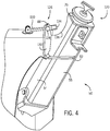
- FIG. 4 is a perspective view of an embodiment of the hydraulic fill system 12 in a retracted position.
- the hydraulic fill system 12 may be less accessible and therefore less susceptible to contact with the operator and to other equipment.
- the operator grabs the prongs 132 and pulls.
- the shaft 130 stretches enabling the enlarged portion 128 of the fastener 126 to be moved out of the notch 88.
- the second wall 54 of the arm 50 may define a recess or cutout 136 to facilitate access to and uncoupling of the fastener 126 from the arm 50.
- FIG. 5 is a partial perspective exploded view of an embodiment of the hydraulic fill system 12.
- the arm 50 may define an aperture 150 in the third wall 55.
- the aperture 150 receives a protrusion 152 on the bracket 86.
- the aperture 150 and protrusion 152 may facilitate alignment and coupling of the bracket 86 with the arm 50 during manufacturing.
- the bracket 86 is welded to the arm 50 or otherwise secured to the arm 50 (e.g., brazed, glued).
- FIG. 6 is a side view of an embodiment of a hydraulic fill system 170.
- the hydraulic fill system 170 includes a plurality of telescoping cylinders 172 (e.g., concentric cylinders) that couple to the tank 30.
- the telescoping cylinders 172 telescope enabling the hydraulic fill system 170 to extend away from the tank 30 in direction 174 to facilitate filling of the tank 30.
- the telescoping cylinders 172 may be collapsed in direction 176 and moved out of the way.
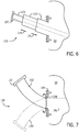
- FIG. 7 is a side view of an embodiment of a hydraulic fill system 190.
- the hydraulic fill system 190 includes a conduit 192 that couples to the tank 30 to facilitate the flow of hydraulic fluid from a source to the tank 30.
- the conduit 192 couples to the tank 30 with a bonnet 194.
- the bonnet 194 enables sealing of the conduit 192 with the tank 30 and retention of the conduit 192 relative to an aperture 196 in a wall of the tank 30. More specifically, the bonnet 194 captures a ledge 198 of the conduit 192 between the bonnet 194 and the tank 30.
- the bonnet 194 also enables the conduit 192 to be rotated between a fill position and a stowed position. Accordingly, when the tank 30 needs fluid, the conduit 192 is rotated to a fill position and once filled rotated out of the way to a stowed position illustrated in dashed lines 200.
Landscapes
- Engineering & Computer Science (AREA)
- Mechanical Engineering (AREA)
- General Engineering & Computer Science (AREA)
- Life Sciences & Earth Sciences (AREA)
- Civil Engineering (AREA)
- Structural Engineering (AREA)
- Mining & Mineral Resources (AREA)
- Soil Sciences (AREA)
- Environmental Sciences (AREA)
- Physics & Mathematics (AREA)
- Fluid Mechanics (AREA)
- Supply Devices, Intensifiers, Converters, And Telemotors (AREA)
- Fertilizing (AREA)
- Catching Or Destruction (AREA)
Abstract
Description
- The present disclosure generally relates to an agricultural system.
- This section is intended to introduce the reader to various aspects of art that may be related to various aspects of the present disclosure, which are described and/or claimed below. This discussion is believed to be helpful in providing the reader with background information to facilitate a better understanding of the various aspects of the present disclosure. Accordingly, it may be understood that these statements are to be read in this light, and not as admissions of prior art.
- Agricultural equipment enables the planting and harvesting of various crops. Some of this equipment may be self-propelled such as a harvester while others may be coupled to a tractor and towed across a field. These pieces of equipment may have a variety of actuators that use hydraulic pressure to operate. For example, a planter may use hydraulic pressure to facilitate forming trenches in the soil, controlling the amount of down pressure on a row unit, and for operating a press wheel to cover the trench. Other uses of hydraulic pressure may include operating brakes, raising/lowering lifts, etc. The hydraulic fluid that powers these various actuators is typically stored in a hydraulic tank. When hydraulic fluid is needed by actuators, it is pressurized and driven by a pump through hydraulic lines to the actuators. Overtime the hydraulic fluid in the tank may be replenished or replaced. Unfortunately, accessing and depositing hydraulic fluid in the hydraulic tank may be cumbersome.
- In one embodiment, an agricultural system that includes a hydraulic fluid tank with a conduit. The hydraulic fluid tank receives and stores hydraulic fluid. A hydraulic fill system couples to and facilitates filling of the hydraulic fluid tank. The hydraulic fill system includes an arm that rotates with respect to the hydraulic fluid tank between an extended position and a retracted position. The arm defines a channel. A connector couples to the arm. The connector defines an opening that receives the hydraulic fluid. A flexible conduit rests within the channel. The flexible conduit includes a first end and a second end. The first end couples to the conduit and the second end couples to the connector.
- These and other features, aspects, and advantages of the present disclosure will become better understood when the following detailed description is read with reference to the accompanying drawings in which like characters represent like parts throughout the drawings, wherein:
-
FIG. 1 is a perspective view of an embodiment of a work vehicle with a hydraulic fill system; -
FIG. 2 is a perspective view of an embodiment of the hydraulic fill system ofFIG. 1 ; -
FIG. 3 is a perspective view of an embodiment of the hydraulic fill system ofFIG. 1 ; -
FIG. 4 is a perspective view of an embodiment of the hydraulic fill system ofFIG. 1 ; -
FIG. 5 is a partial perspective exploded view of an embodiment of the hydraulic fill system; -
FIG. 6 is a side view of an embodiment of a hydraulic fill system; and -
FIG. 7 is a side view of an embodiment of a hydraulic fill system. - One or more specific embodiments of the present disclosure will be described below.
- When introducing elements of various embodiments of the present disclosure, the articles "a," "an," "the," and "said" are intended to mean that there are one or more of the elements. The terms "comprising," "including," and "having" are intended to be inclusive and mean that there may be additional elements other than the listed elements. Moreover, the use of "top," "bottom," "above," "below," and variations of these terms is made for convenience, but does not require any particular orientation of the components.
-
FIG. 1 is a perspective view of an embodiment of awork vehicle 10 with ahydraulic fill system 12. As illustrated, thework vehicle 10 may be a tractor; however, in other embodiments the work vehicle may be truck, harvester, or another type of agricultural vehicle. Thework vehicle 10 includes acab 14 supported by achassis 16. Thechassis 16 may also support a motor 18 (e.g., diesel engine, etc.), abrake system 20, asteering control system 22, ahydraulic system 24, among other components (e.g., an electrical system, a cooling system, etc.) that facilitate operation of thework vehicle 10. - During operation, the
motor 18 provides power that driveswheels 26. Themotor 18 may also provide power to thehydraulic system 24. For example, thehydraulic system 24 may include pump(s), valves, a reservoir, etc. In operation, themotor 18 provides power to a pump(s), which generates hydraulic pressure with the hydraulic fluid stored in the reservoir. The hydraulic fluid may then be directed using a series of valves to drive various systems on thework vehicle 10. These systems may include thebrake system 20, thesteering system 22, a lift, among others. The hydraulic pressure may also be used to operate equipment coupled to thework vehicle 10. In order to transfer pressurized hydraulic fluid from thework vehicle 10, thework vehicle 10 may include one or morehydraulic fluid connectors 28 that couple thehydraulic system 24 to other equipment. For example, theconnectors 28 may enable pressurized hydraulic fluid to flow from thehydraulic system 24 to an agricultural implement coupled to thework vehicle 10, such as a planter. In operation, the planter uses the pressurized hydraulic fluid to drive various actuators to control down pressure on row units, depth of trenches, the degree of soil packing, etc. Other agricultural implements may use the pressurized hydraulic fluid to perform different operations, such as harvesting. - The
hydraulic system 24 includes ahydraulic tank 30 that stores hydraulic fluid used by thehydraulic system 24 to control or operate various systems on thework vehicle 10. Periodically, thetank 30 may be refilled, such as when the hydraulic fluid is drained and then refilled. To facilitate filling thetank 30, thework vehicle 10 includes thehydraulic fill system 12. Thehydraulic fill system 12 facilitates access to thetank 30, which may enable controlled filling of thetank 30. After using thehydraulic fill system 12, thehydraulic fill system 12 is stored on thework vehicle 10 and out of the way of other equipment. -
FIG. 2 is a perspective view of an embodiment of thehydraulic fill system 12 ofFIG. 1 . Thehydraulic fill system 12 includes anarm 50 with first, second, andthird walls channel 56. Thearm 50 couples to thework vehicle 10 with first andsecond connectors first connector 58 couples thefirst wall 52 to afirst flange 62, and thesecond connector 60 couples thesecond wall 54 to asecond flange 64. The first andsecond flanges hydraulic fill system 12 to couple to thework vehicle 10. The first andsecond connectors arm 50 to rotate between extended and retracted positions. That is, as thearm 50 rotates indirection 65 it transitions to a retracted position, and as thearm 50 rotates indirection 66 it transitions to an extended position. Thearm 50 rotates indirection 66 until thethird wall 55 contacts aconduit 68 that extends fromsurface 70. In some embodiments, athird flange 72 may couple to the first andsecond flanges third flange 72, thearm 50 rotates until it contacts thethird flange 72. - The
channel 56 formed by the first, second,third walls flexible conduit 74. Theflexible conduit 74 may be made out of a variety of materials including a rubber, a polymer(s), or a combination thereof. Theflexible conduit 74 couples to the conduit 68 (e.g., rigid conduit) enabling the hydraulic fluid to be poured through theflexible conduit 74, theconduit 68, and into thetank 30. Coupling theflexible conduit 74 to therigid conduit 68 enables thearm 50 to rotate between the extended and retracted positions. In some embodiments, thearm 50 may rotate between 10-50 degrees with respect to thesurface 70 in order to block theflexible conduit 74 from kinking. - As illustrated, the
flexible conduit 74 extends between theconduit 68 and aconnector 76 with afirst end 78 coupling to theconduit 68 and thesecond end 80 coupling to theconnector 76. For example, thefirst end 78 may extend over a portion of theconduit 68 and thesecond end 80 may extend over a portion of theconnector 76. To secure theconduit 68 in place,ring bands ring band 84 wraps around theflexible conduit 74 and theconduit 68 securing theflexible conduit 74 to theconduit 68. Thering band 82 may also facilitate formation and maintenance of a fluid tight seal between theflexible conduit 74 and theconduit 68 as thearm 50 moves between extended and retracted positions. - As will be explained below, the
hydraulic fill system 12 includes a retention bracket orflange 86 that couples to thearm 50. Thebracket 86 defines anotch 88 that enables thearm 50 to couple to thework vehicle 10 in a retracted position. -
FIG. 3 is a perspective view of an embodiment of thehydraulic fill system 12 ofFIG. 1 in an extended position. In this position, the hydraulic fill system facilitates access to and enables hydraulic fluid to be poured into thetank 30. More specifically, an operator is easily able to access thelid 120. Removal of thelid 120 provides access to theopening 122 in theconnector 76. Hydraulic fluid may then be poured into theconnector 76, which then passes through theflexible conduit 74 to thetank 30. Thus, by including theflexible conduit 74 supported by thearm 50, hydraulic fluid may be poured into thetank 30 at a convenient position away from thework vehicle 10. In other words, thehydraulic fill system 12 extends the opening (e.g., opening in conduit 68) further away from thework vehicle 10 so that other equipment on the work vehicle 10 (e.g., steps, hoses, bars) is less able to interfere with the transfer of hydraulic fluid to thetank 30. - In order to secure the
hydraulic fill system 12 in a retracted position, thehydraulic fill system 12 includes aretention system 124. Theretention system 124 includes thebracket 86 and afastener 126. Thebracket 86 couples to thearm 50. In some embodiments, thebracket 86 may be coupled (e.g., welded, made out one-piece) to the second andthird walls third walls bracket 86 may be securely coupled to thearm 50 during operation of thework vehicle 10. - As explained above, the
bracket 86 includes thenotch 88. Thenotch 88 is configured to receive thefastener 126. Thefastener 126 couples to thework vehicle 10 and includes an enlarged portion 128 (e.g., ball) coupled to ashaft 130. Thefastener 126 includes a flexible material that enables theshaft 130 to be stretched and to contract. When coupled to thebracket 86, theshaft 130 is stretched as the operator pulls. Theenlarged portion 128 is then placed into contact with thenotch 88 on aside 132 of thebracket 86 facing away from thefastener 126, as illustrated inFIG. 4 . When the operator releases thefastener 126, theshaft 130 contracts and applies a force on thearm 50, which reduces or blocks rotation of thearm 50. To facilitate stretching of theshaft 130 when coupling to thebracket 86, thefastener 126 may includeprongs 132 that enable the operator to grab and pull thefastener 126. -
FIG. 4 is a perspective view of an embodiment of thehydraulic fill system 12 in a retracted position. In the retracted position, thehydraulic fill system 12 may be less accessible and therefore less susceptible to contact with the operator and to other equipment. In order to release thehydraulic fill system 12 and access thetank 30, the operator grabs theprongs 132 and pulls. As the operator pulls, theshaft 130 stretches enabling theenlarged portion 128 of thefastener 126 to be moved out of thenotch 88. In some embodiments, thesecond wall 54 of thearm 50 may define a recess orcutout 136 to facilitate access to and uncoupling of thefastener 126 from thearm 50. -
FIG. 5 is a partial perspective exploded view of an embodiment of thehydraulic fill system 12. As illustrated, thearm 50 may define anaperture 150 in thethird wall 55. Theaperture 150 receives aprotrusion 152 on thebracket 86. Theaperture 150 andprotrusion 152 may facilitate alignment and coupling of thebracket 86 with thearm 50 during manufacturing. In some embodiments, after placing theprotrusion 152 in theaperture 150, thebracket 86 is welded to thearm 50 or otherwise secured to the arm 50 (e.g., brazed, glued). -
FIG. 6 is a side view of an embodiment of ahydraulic fill system 170. InFIG. 6 , thehydraulic fill system 170 includes a plurality of telescoping cylinders 172 (e.g., concentric cylinders) that couple to thetank 30. Thetelescoping cylinders 172 telescope enabling thehydraulic fill system 170 to extend away from thetank 30 indirection 174 to facilitate filling of thetank 30. After filling thetank 30, thetelescoping cylinders 172 may be collapsed indirection 176 and moved out of the way. -
FIG. 7 is a side view of an embodiment of ahydraulic fill system 190. Thehydraulic fill system 190 includes aconduit 192 that couples to thetank 30 to facilitate the flow of hydraulic fluid from a source to thetank 30. Theconduit 192 couples to thetank 30 with abonnet 194. Thebonnet 194 enables sealing of theconduit 192 with thetank 30 and retention of theconduit 192 relative to anaperture 196 in a wall of thetank 30. More specifically, thebonnet 194 captures aledge 198 of theconduit 192 between thebonnet 194 and thetank 30. Thebonnet 194 also enables theconduit 192 to be rotated between a fill position and a stowed position. Accordingly, when thetank 30 needs fluid, theconduit 192 is rotated to a fill position and once filled rotated out of the way to a stowed position illustrated in dashedlines 200. - While the embodiments disclosed herein may be susceptible to various modifications and alternative forms, specific embodiments have been shown by way of example in the drawings and have been described in detail herein. However, it should be understood that the disclosure is not intended to be limited to the particular forms disclosed. Rather, the disclosure is to cover all modifications, equivalents, and alternatives falling within the spirit and scope of the disclosure as defined by the following appended claims.
Claims (11)
- A hydraulic fill system (12) for a working vehicle (10) configured to couple to and facilitate filling of a hydraulic fluid tank (30) of said working vehicle (10), said hydraulic fluid tank (30) comprising a conduit (68) and configured to receive and store hydraulic fluid;
said hydraulic fill system (12) comprising:an arm (50) configured to rotate with respect to the hydraulic fluid tank (30) between an extended position and a retracted position, the arm (50) defining a channel (56);a connector (76) coupled to the arm (50), wherein the connector (28) defines an opening configured to receive hydraulic fluid; anda flexible conduit (74) within the channel (56), the flexible conduit (74) defining a first end (78) and a second end (80), wherein the first end (78) couples to the conduit (68) and the second end couples to the connector (76). - The system of claim 1, comprising a retention system (124) configured to secure the arm (50) in the retracted position.
- The system of claim 2, wherein the retention system (124) comprises a bracket (86) coupled to the arm (50), the bracket defining a notch (88).
- The system of claim 3, wherein the retention system (124) comprises a bracket (86) to block or reduce rotation of the arm (50) by coupling with a fastener (126) of said work vehicle (10).
- The system of claim 4, wherein the arm (50) comprises a wall (54), wherein the wall (54) defines a recess (136) that provides access to said fastener (126).
- The system of claim 5, wherein the bracket (86) includes a notch (88) configured for holding an enlarged portion (128) of a shaft (130) coupled to the working vehicle (10).
- The system of claim 1, comprising first and second flanges (62,64) configured to be coupled to the hydraulic fluid tank (30), and wherein the arm (50) couples to the first and second flanges (62,64) with a first connector (58,60) and a second connector (58,60).
- The system of claim 1, wherein the arm (50) is configured to rotate between 10 and 50 degrees.
- The system of claim 1, comprising a first ring band (82) and a second ring band (84), wherein the first ring band (82) couples the flexible conduit (74) to the conduit (68), and the second ring band (84) couples the flexible conduit (74) to the connector (76).
- The system of claim 1, wherein the flexible conduit (74) has a first stiffness and the conduit has a second stiffness (68), wherein the first stiffness is less than the second stiffness.
- A work vehicle (10) comprising the hydraulic fluid tank (30) and the hydraulic fill system (12) according to any of the preceding claim.
Applications Claiming Priority (1)
| Application Number | Priority Date | Filing Date | Title |
|---|---|---|---|
| US16/168,351 US20200123941A1 (en) | 2018-10-23 | 2018-10-23 | Hydraulic fill system |
Publications (2)
| Publication Number | Publication Date |
|---|---|
| EP3643841A1 true EP3643841A1 (en) | 2020-04-29 |
| EP3643841B1 EP3643841B1 (en) | 2022-08-31 |
Family
ID=68342500
Family Applications (1)
| Application Number | Title | Priority Date | Filing Date |
|---|---|---|---|
| EP19204599.5A Active EP3643841B1 (en) | 2018-10-23 | 2019-10-22 | Hydraulic fill system |
Country Status (4)
| Country | Link |
|---|---|
| US (1) | US20200123941A1 (en) |
| EP (1) | EP3643841B1 (en) |
| CN (1) | CN111083951B (en) |
| AU (1) | AU2019253819A1 (en) |
Families Citing this family (1)
| Publication number | Priority date | Publication date | Assignee | Title |
|---|---|---|---|---|
| JP7721587B2 (en) * | 2023-02-27 | 2025-08-12 | 株式会社竹内製作所 | Work vehicles |
Citations (4)
| Publication number | Priority date | Publication date | Assignee | Title |
|---|---|---|---|---|
| CA858885A (en) * | 1970-12-22 | Allis-Chalmers Manufacturing Company | Pressure release device for a hydraulic tank | |
| US5426805A (en) * | 1993-08-24 | 1995-06-27 | Waldon, Inc. | Walk-behind self-propelled broom sweeper |
| US5794805A (en) * | 1994-11-14 | 1998-08-18 | New Holland North America Inc. | Fuel tank assembly for skid steer loaders |
| CN102554178A (en) * | 2012-02-21 | 2012-07-11 | 重庆大江美利信压铸有限责任公司 | Hydraulic oil filling interface of die casting machine |
Family Cites Families (12)
| Publication number | Priority date | Publication date | Assignee | Title |
|---|---|---|---|---|
| US1662820A (en) * | 1927-06-17 | 1928-03-20 | Condupa Michael | Oil filler for automobiles |
| US2578184A (en) * | 1946-06-11 | 1951-12-11 | John R Green | Oil filler neck extension for automobile engines |
| AT380212B (en) * | 1982-11-17 | 1986-04-25 | Steyr Daimler Puch Ag | FUEL DEVICE FOR FUEL IN MOTOR VEHICLES |
| US4530537A (en) * | 1983-09-06 | 1985-07-23 | J. I. Case Company | Moveable filler assembly |
| US6363905B1 (en) * | 2000-10-30 | 2002-04-02 | Tecumseh Products Company | Flexible oil fill tube |
| DE20212980U1 (en) * | 2002-08-23 | 2003-01-02 | MAN Nutzfahrzeuge AG, 80995 München | Oil filler device for commercial vehicles |
| JP2004098945A (en) * | 2002-09-11 | 2004-04-02 | Honda Motor Co Ltd | Refueling port structure for small watercraft |
| US6830085B1 (en) * | 2004-03-29 | 2004-12-14 | Thomas A Majewski | Fuel tank inlet extension |
| ES2318980B1 (en) * | 2006-07-25 | 2010-02-15 | Fico Transpar, S.A. | CONTAINER CONTAINER FOR LIQUID WINDSHIELD OR WASHERS IN A VEHICLE. |
| US20110192843A1 (en) * | 2010-02-08 | 2011-08-11 | International Engine Intellectual Property Company Llc | Engine with remote oil fill assembly |
| US9010500B2 (en) * | 2011-04-28 | 2015-04-21 | Shimano Inc. | Hydraulic brake hose structure |
| CN203962521U (en) * | 2014-07-24 | 2014-11-26 | 广西澜光科技有限公司 | Tractor hydraulic fuel tank |
-
2018
- 2018-10-23 US US16/168,351 patent/US20200123941A1/en not_active Abandoned
-
2019
- 2019-08-30 CN CN201910811020.XA patent/CN111083951B/en active Active
- 2019-10-22 EP EP19204599.5A patent/EP3643841B1/en active Active
- 2019-10-22 AU AU2019253819A patent/AU2019253819A1/en not_active Abandoned
Patent Citations (4)
| Publication number | Priority date | Publication date | Assignee | Title |
|---|---|---|---|---|
| CA858885A (en) * | 1970-12-22 | Allis-Chalmers Manufacturing Company | Pressure release device for a hydraulic tank | |
| US5426805A (en) * | 1993-08-24 | 1995-06-27 | Waldon, Inc. | Walk-behind self-propelled broom sweeper |
| US5794805A (en) * | 1994-11-14 | 1998-08-18 | New Holland North America Inc. | Fuel tank assembly for skid steer loaders |
| CN102554178A (en) * | 2012-02-21 | 2012-07-11 | 重庆大江美利信压铸有限责任公司 | Hydraulic oil filling interface of die casting machine |
Also Published As
| Publication number | Publication date |
|---|---|
| EP3643841B1 (en) | 2022-08-31 |
| CN111083951A (en) | 2020-05-01 |
| CN111083951B (en) | 2023-02-10 |
| AU2019253819A1 (en) | 2020-05-07 |
| US20200123941A1 (en) | 2020-04-23 |
| BR102019022124A2 (en) | 2020-05-05 |
Similar Documents
| Publication | Publication Date | Title |
|---|---|---|
| EP3643841B1 (en) | Hydraulic fill system | |
| US4643442A (en) | Fluid supply system for working vehicles | |
| US20220260064A1 (en) | Hydraulic Power Units with Submerged Motors | |
| KR102023384B1 (en) | Height adjusters for agricultural tractor | |
| WO2004098263A2 (en) | An agricultural implement hitch | |
| JP5338717B2 (en) | Seedling transplanter | |
| US7931301B2 (en) | Traveling vehicle | |
| JP2011177052A5 (en) | ||
| EP1795061B1 (en) | Hydraulic lift structure | |
| JP3427018B2 (en) | Lateral feed mechanism of seedling planting equipment | |
| KR0140935B1 (en) | Agricultural General Manager | |
| CN204180515U (en) | Hydraulic-driven saddle type rice transplanter | |
| KR102040980B1 (en) | Tractor attachment detachable device | |
| JP2575692Y2 (en) | Working machine for topdressing equipment | |
| BR102019022124B1 (en) | HYDRAULIC FILLING SYSTEM AND WORK VEHICLE | |
| US10736261B2 (en) | Work vehicle | |
| JP6176499B2 (en) | Transplanter | |
| WO2023014350A1 (en) | Submersible hydraulic power units with interchangeable manifolds | |
| JP2016149974A (en) | Work vehicle | |
| US20200240103A1 (en) | Tool stabilizer system | |
| JP2003095292A (en) | Agricultural work equipment fuel tank structure | |
| US20100237687A1 (en) | Arrangement for venting of hydraulic system in motor vehicle | |
| JP2016136933A5 (en) | ||
| JPH08275641A (en) | Liquid injection device | |
| JP2001269021A (en) | Seedling plant |
Legal Events
| Date | Code | Title | Description |
|---|---|---|---|
| PUAI | Public reference made under article 153(3) epc to a published international application that has entered the european phase |
Free format text: ORIGINAL CODE: 0009012 |
|
| STAA | Information on the status of an ep patent application or granted ep patent |
Free format text: STATUS: THE APPLICATION HAS BEEN PUBLISHED |
|
| AK | Designated contracting states |
Kind code of ref document: A1 Designated state(s): AL AT BE BG CH CY CZ DE DK EE ES FI FR GB GR HR HU IE IS IT LI LT LU LV MC MK MT NL NO PL PT RO RS SE SI SK SM TR |
|
| AX | Request for extension of the european patent |
Extension state: BA ME |
|
| STAA | Information on the status of an ep patent application or granted ep patent |
Free format text: STATUS: REQUEST FOR EXAMINATION WAS MADE |
|
| 17P | Request for examination filed |
Effective date: 20201029 |
|
| RBV | Designated contracting states (corrected) |
Designated state(s): AL AT BE BG CH CY CZ DE DK EE ES FI FR GB GR HR HU IE IS IT LI LT LU LV MC MK MT NL NO PL PT RO RS SE SI SK SM TR |
|
| STAA | Information on the status of an ep patent application or granted ep patent |
Free format text: STATUS: EXAMINATION IS IN PROGRESS |
|
| 17Q | First examination report despatched |
Effective date: 20210311 |
|
| GRAP | Despatch of communication of intention to grant a patent |
Free format text: ORIGINAL CODE: EPIDOSNIGR1 |
|
| STAA | Information on the status of an ep patent application or granted ep patent |
Free format text: STATUS: GRANT OF PATENT IS INTENDED |
|
| INTG | Intention to grant announced |
Effective date: 20211006 |
|
| GRAJ | Information related to disapproval of communication of intention to grant by the applicant or resumption of examination proceedings by the epo deleted |
Free format text: ORIGINAL CODE: EPIDOSDIGR1 |
|
| STAA | Information on the status of an ep patent application or granted ep patent |
Free format text: STATUS: EXAMINATION IS IN PROGRESS |
|
| GRAP | Despatch of communication of intention to grant a patent |
Free format text: ORIGINAL CODE: EPIDOSNIGR1 |
|
| STAA | Information on the status of an ep patent application or granted ep patent |
Free format text: STATUS: GRANT OF PATENT IS INTENDED |
|
| INTC | Intention to grant announced (deleted) | ||
| INTG | Intention to grant announced |
Effective date: 20220321 |
|
| GRAS | Grant fee paid |
Free format text: ORIGINAL CODE: EPIDOSNIGR3 |
|
| GRAA | (expected) grant |
Free format text: ORIGINAL CODE: 0009210 |
|
| STAA | Information on the status of an ep patent application or granted ep patent |
Free format text: STATUS: THE PATENT HAS BEEN GRANTED |
|
| AK | Designated contracting states |
Kind code of ref document: B1 Designated state(s): AL AT BE BG CH CY CZ DE DK EE ES FI FR GB GR HR HU IE IS IT LI LT LU LV MC MK MT NL NO PL PT RO RS SE SI SK SM TR |
|
| REG | Reference to a national code |
Ref country code: CH Ref legal event code: EP Ref country code: GB Ref legal event code: FG4D |
|
| REG | Reference to a national code |
Ref country code: AT Ref legal event code: REF Ref document number: 1515374 Country of ref document: AT Kind code of ref document: T Effective date: 20220915 |
|
| REG | Reference to a national code |
Ref country code: DE Ref legal event code: R096 Ref document number: 602019018897 Country of ref document: DE |
|
| REG | Reference to a national code |
Ref country code: IE Ref legal event code: FG4D |
|
| REG | Reference to a national code |
Ref country code: LT Ref legal event code: MG9D |
|
| REG | Reference to a national code |
Ref country code: NL Ref legal event code: MP Effective date: 20220831 |
|
| PG25 | Lapsed in a contracting state [announced via postgrant information from national office to epo] |
Ref country code: SE Free format text: LAPSE BECAUSE OF FAILURE TO SUBMIT A TRANSLATION OF THE DESCRIPTION OR TO PAY THE FEE WITHIN THE PRESCRIBED TIME-LIMIT Effective date: 20220831 Ref country code: RS Free format text: LAPSE BECAUSE OF FAILURE TO SUBMIT A TRANSLATION OF THE DESCRIPTION OR TO PAY THE FEE WITHIN THE PRESCRIBED TIME-LIMIT Effective date: 20220831 Ref country code: NO Free format text: LAPSE BECAUSE OF FAILURE TO SUBMIT A TRANSLATION OF THE DESCRIPTION OR TO PAY THE FEE WITHIN THE PRESCRIBED TIME-LIMIT Effective date: 20221130 Ref country code: LV Free format text: LAPSE BECAUSE OF FAILURE TO SUBMIT A TRANSLATION OF THE DESCRIPTION OR TO PAY THE FEE WITHIN THE PRESCRIBED TIME-LIMIT Effective date: 20220831 Ref country code: LT Free format text: LAPSE BECAUSE OF FAILURE TO SUBMIT A TRANSLATION OF THE DESCRIPTION OR TO PAY THE FEE WITHIN THE PRESCRIBED TIME-LIMIT Effective date: 20220831 Ref country code: FI Free format text: LAPSE BECAUSE OF FAILURE TO SUBMIT A TRANSLATION OF THE DESCRIPTION OR TO PAY THE FEE WITHIN THE PRESCRIBED TIME-LIMIT Effective date: 20220831 |
|
| REG | Reference to a national code |
Ref country code: AT Ref legal event code: MK05 Ref document number: 1515374 Country of ref document: AT Kind code of ref document: T Effective date: 20220831 |
|
| PG25 | Lapsed in a contracting state [announced via postgrant information from national office to epo] |
Ref country code: PL Free format text: LAPSE BECAUSE OF FAILURE TO SUBMIT A TRANSLATION OF THE DESCRIPTION OR TO PAY THE FEE WITHIN THE PRESCRIBED TIME-LIMIT Effective date: 20220831 Ref country code: IS Free format text: LAPSE BECAUSE OF FAILURE TO SUBMIT A TRANSLATION OF THE DESCRIPTION OR TO PAY THE FEE WITHIN THE PRESCRIBED TIME-LIMIT Effective date: 20221231 Ref country code: HR Free format text: LAPSE BECAUSE OF FAILURE TO SUBMIT A TRANSLATION OF THE DESCRIPTION OR TO PAY THE FEE WITHIN THE PRESCRIBED TIME-LIMIT Effective date: 20220831 Ref country code: GR Free format text: LAPSE BECAUSE OF FAILURE TO SUBMIT A TRANSLATION OF THE DESCRIPTION OR TO PAY THE FEE WITHIN THE PRESCRIBED TIME-LIMIT Effective date: 20221201 |
|
| PG25 | Lapsed in a contracting state [announced via postgrant information from national office to epo] |
Ref country code: SM Free format text: LAPSE BECAUSE OF FAILURE TO SUBMIT A TRANSLATION OF THE DESCRIPTION OR TO PAY THE FEE WITHIN THE PRESCRIBED TIME-LIMIT Effective date: 20220831 Ref country code: RO Free format text: LAPSE BECAUSE OF FAILURE TO SUBMIT A TRANSLATION OF THE DESCRIPTION OR TO PAY THE FEE WITHIN THE PRESCRIBED TIME-LIMIT Effective date: 20220831 Ref country code: PT Free format text: LAPSE BECAUSE OF FAILURE TO SUBMIT A TRANSLATION OF THE DESCRIPTION OR TO PAY THE FEE WITHIN THE PRESCRIBED TIME-LIMIT Effective date: 20230102 Ref country code: ES Free format text: LAPSE BECAUSE OF FAILURE TO SUBMIT A TRANSLATION OF THE DESCRIPTION OR TO PAY THE FEE WITHIN THE PRESCRIBED TIME-LIMIT Effective date: 20220831 Ref country code: DK Free format text: LAPSE BECAUSE OF FAILURE TO SUBMIT A TRANSLATION OF THE DESCRIPTION OR TO PAY THE FEE WITHIN THE PRESCRIBED TIME-LIMIT Effective date: 20220831 Ref country code: CZ Free format text: LAPSE BECAUSE OF FAILURE TO SUBMIT A TRANSLATION OF THE DESCRIPTION OR TO PAY THE FEE WITHIN THE PRESCRIBED TIME-LIMIT Effective date: 20220831 Ref country code: AT Free format text: LAPSE BECAUSE OF FAILURE TO SUBMIT A TRANSLATION OF THE DESCRIPTION OR TO PAY THE FEE WITHIN THE PRESCRIBED TIME-LIMIT Effective date: 20220831 |
|
| PG25 | Lapsed in a contracting state [announced via postgrant information from national office to epo] |
Ref country code: SK Free format text: LAPSE BECAUSE OF FAILURE TO SUBMIT A TRANSLATION OF THE DESCRIPTION OR TO PAY THE FEE WITHIN THE PRESCRIBED TIME-LIMIT Effective date: 20220831 Ref country code: MC Free format text: LAPSE BECAUSE OF FAILURE TO SUBMIT A TRANSLATION OF THE DESCRIPTION OR TO PAY THE FEE WITHIN THE PRESCRIBED TIME-LIMIT Effective date: 20220831 Ref country code: EE Free format text: LAPSE BECAUSE OF FAILURE TO SUBMIT A TRANSLATION OF THE DESCRIPTION OR TO PAY THE FEE WITHIN THE PRESCRIBED TIME-LIMIT Effective date: 20220831 |
|
| REG | Reference to a national code |
Ref country code: CH Ref legal event code: PL |
|
| REG | Reference to a national code |
Ref country code: DE Ref legal event code: R097 Ref document number: 602019018897 Country of ref document: DE |
|
| REG | Reference to a national code |
Ref country code: BE Ref legal event code: MM Effective date: 20221031 |
|
| RAP4 | Party data changed (patent owner data changed or rights of a patent transferred) |
Owner name: CNH INDUSTRIAL ITALIA S.P.A. |
|
| PG25 | Lapsed in a contracting state [announced via postgrant information from national office to epo] |
Ref country code: NL Free format text: LAPSE BECAUSE OF FAILURE TO SUBMIT A TRANSLATION OF THE DESCRIPTION OR TO PAY THE FEE WITHIN THE PRESCRIBED TIME-LIMIT Effective date: 20220831 Ref country code: LU Free format text: LAPSE BECAUSE OF NON-PAYMENT OF DUE FEES Effective date: 20221022 Ref country code: AL Free format text: LAPSE BECAUSE OF FAILURE TO SUBMIT A TRANSLATION OF THE DESCRIPTION OR TO PAY THE FEE WITHIN THE PRESCRIBED TIME-LIMIT Effective date: 20220831 |
|
| PLBE | No opposition filed within time limit |
Free format text: ORIGINAL CODE: 0009261 |
|
| STAA | Information on the status of an ep patent application or granted ep patent |
Free format text: STATUS: NO OPPOSITION FILED WITHIN TIME LIMIT |
|
| PG25 | Lapsed in a contracting state [announced via postgrant information from national office to epo] |
Ref country code: LI Free format text: LAPSE BECAUSE OF NON-PAYMENT OF DUE FEES Effective date: 20221031 Ref country code: CH Free format text: LAPSE BECAUSE OF NON-PAYMENT OF DUE FEES Effective date: 20221031 |
|
| 26N | No opposition filed |
Effective date: 20230601 |
|
| PG25 | Lapsed in a contracting state [announced via postgrant information from national office to epo] |
Ref country code: SI Free format text: LAPSE BECAUSE OF FAILURE TO SUBMIT A TRANSLATION OF THE DESCRIPTION OR TO PAY THE FEE WITHIN THE PRESCRIBED TIME-LIMIT Effective date: 20220831 |
|
| PG25 | Lapsed in a contracting state [announced via postgrant information from national office to epo] |
Ref country code: BE Free format text: LAPSE BECAUSE OF NON-PAYMENT OF DUE FEES Effective date: 20221031 |
|
| PG25 | Lapsed in a contracting state [announced via postgrant information from national office to epo] |
Ref country code: IE Free format text: LAPSE BECAUSE OF NON-PAYMENT OF DUE FEES Effective date: 20221022 |
|
| PG25 | Lapsed in a contracting state [announced via postgrant information from national office to epo] |
Ref country code: HU Free format text: LAPSE BECAUSE OF FAILURE TO SUBMIT A TRANSLATION OF THE DESCRIPTION OR TO PAY THE FEE WITHIN THE PRESCRIBED TIME-LIMIT; INVALID AB INITIO Effective date: 20191022 |
|
| PG25 | Lapsed in a contracting state [announced via postgrant information from national office to epo] |
Ref country code: CY Free format text: LAPSE BECAUSE OF FAILURE TO SUBMIT A TRANSLATION OF THE DESCRIPTION OR TO PAY THE FEE WITHIN THE PRESCRIBED TIME-LIMIT Effective date: 20220831 |
|
| PG25 | Lapsed in a contracting state [announced via postgrant information from national office to epo] |
Ref country code: MK Free format text: LAPSE BECAUSE OF FAILURE TO SUBMIT A TRANSLATION OF THE DESCRIPTION OR TO PAY THE FEE WITHIN THE PRESCRIBED TIME-LIMIT Effective date: 20220831 |
|
| PG25 | Lapsed in a contracting state [announced via postgrant information from national office to epo] |
Ref country code: TR Free format text: LAPSE BECAUSE OF FAILURE TO SUBMIT A TRANSLATION OF THE DESCRIPTION OR TO PAY THE FEE WITHIN THE PRESCRIBED TIME-LIMIT Effective date: 20220831 |
|
| PG25 | Lapsed in a contracting state [announced via postgrant information from national office to epo] |
Ref country code: BG Free format text: LAPSE BECAUSE OF FAILURE TO SUBMIT A TRANSLATION OF THE DESCRIPTION OR TO PAY THE FEE WITHIN THE PRESCRIBED TIME-LIMIT Effective date: 20220831 |
|
| PG25 | Lapsed in a contracting state [announced via postgrant information from national office to epo] |
Ref country code: MT Free format text: LAPSE BECAUSE OF FAILURE TO SUBMIT A TRANSLATION OF THE DESCRIPTION OR TO PAY THE FEE WITHIN THE PRESCRIBED TIME-LIMIT Effective date: 20220831 |
|
| PGFP | Annual fee paid to national office [announced via postgrant information from national office to epo] |
Ref country code: DE Payment date: 20251028 Year of fee payment: 7 |
|
| PGFP | Annual fee paid to national office [announced via postgrant information from national office to epo] |
Ref country code: GB Payment date: 20251021 Year of fee payment: 7 |
|
| PGFP | Annual fee paid to national office [announced via postgrant information from national office to epo] |
Ref country code: IT Payment date: 20251024 Year of fee payment: 7 |
|
| PGFP | Annual fee paid to national office [announced via postgrant information from national office to epo] |
Ref country code: FR Payment date: 20251027 Year of fee payment: 7 |