EP3643543B1 - Double solenoid in trailer air suspension control device - Google Patents
Double solenoid in trailer air suspension control device Download PDFInfo
- Publication number
- EP3643543B1 EP3643543B1 EP18202835.7A EP18202835A EP3643543B1 EP 3643543 B1 EP3643543 B1 EP 3643543B1 EP 18202835 A EP18202835 A EP 18202835A EP 3643543 B1 EP3643543 B1 EP 3643543B1
- Authority
- EP
- European Patent Office
- Prior art keywords
- port
- valve
- lifting
- lowering
- bellows
- Prior art date
- Legal status (The legal status is an assumption and is not a legal conclusion. Google has not performed a legal analysis and makes no representation as to the accuracy of the status listed.)
- Active
Links
- 239000000725 suspension Substances 0.000 title claims description 13
- 239000012530 fluid Substances 0.000 claims description 6
- 230000001419 dependent effect Effects 0.000 description 3
- 230000006870 function Effects 0.000 description 3
- 238000005273 aeration Methods 0.000 description 2
- 238000010276 construction Methods 0.000 description 2
- 238000013022 venting Methods 0.000 description 2
- 230000007613 environmental effect Effects 0.000 description 1
- 230000008571 general function Effects 0.000 description 1
Images

Classifications
-
- B—PERFORMING OPERATIONS; TRANSPORTING
- B60—VEHICLES IN GENERAL
- B60G—VEHICLE SUSPENSION ARRANGEMENTS
- B60G17/00—Resilient suspensions having means for adjusting the spring or vibration-damper characteristics, for regulating the distance between a supporting surface and a sprung part of vehicle or for locking suspension during use to meet varying vehicular or surface conditions, e.g. due to speed or load
- B60G17/005—Suspension locking arrangements
-
- B—PERFORMING OPERATIONS; TRANSPORTING
- B60—VEHICLES IN GENERAL
- B60G—VEHICLE SUSPENSION ARRANGEMENTS
- B60G17/00—Resilient suspensions having means for adjusting the spring or vibration-damper characteristics, for regulating the distance between a supporting surface and a sprung part of vehicle or for locking suspension during use to meet varying vehicular or surface conditions, e.g. due to speed or load
- B60G17/02—Spring characteristics, e.g. mechanical springs and mechanical adjusting means
- B60G17/04—Spring characteristics, e.g. mechanical springs and mechanical adjusting means fluid spring characteristics
- B60G17/052—Pneumatic spring characteristics
- B60G17/0523—Regulating distributors or valves for pneumatic springs
- B60G17/0525—Height adjusting or levelling valves
-
- B—PERFORMING OPERATIONS; TRANSPORTING
- B60—VEHICLES IN GENERAL
- B60G—VEHICLE SUSPENSION ARRANGEMENTS
- B60G2204/00—Indexing codes related to suspensions per se or to auxiliary parts
- B60G2204/40—Auxiliary suspension parts; Adjustment of suspensions
- B60G2204/46—Means for locking the suspension
-
- B—PERFORMING OPERATIONS; TRANSPORTING
- B60—VEHICLES IN GENERAL
- B60G—VEHICLE SUSPENSION ARRANGEMENTS
- B60G2300/00—Indexing codes relating to the type of vehicle
- B60G2300/04—Trailers
-
- B—PERFORMING OPERATIONS; TRANSPORTING
- B60—VEHICLES IN GENERAL
- B60G—VEHICLE SUSPENSION ARRANGEMENTS
- B60G2500/00—Indexing codes relating to the regulated action or device
- B60G2500/20—Spring action or springs
- B60G2500/202—Height or leveling valve for air-springs
- B60G2500/2021—Arrangement of valves
Definitions
- the invention relates to a valve device for an air suspension system in a vehicle, comprising a supply port for receiving a supply pressure, at least a first bellows port for providing a first bellows pressure, a first lifting/lowering valve manually operable by a hand lever and in fluid connection with the supply port and the first bellows port, wherein the hand lever is operable to selectively connect the first bellows port with the supply port for providing the first bellows pressure, and a locking unit for locking the position of the hand lever, the locking unit comprising a locking valve biased into the locking position and comprising a release chamber, wherein the locking valve is switchable into a release position upon a release pressure being supplied into the release chamber.
- valve devices are used to regulate the air volume in suspension bellows of an air suspension system.
- they regulate the level of the trailer with respect to the truck of the vehicle, towing the trailer.
- Increase and decrease of the air volume in the bellows is electronically controlled by an electronic control unit according to detected requirements.
- it is necessary to manually regulate the air volume in the bellows, e.g. during loading and unloading the trailer, for e.g. adapting the level of the trailer with respect to a loading ramp.
- separate valve elements have been used in the past which are manually operable for lifting or lowering the trailer with respect to the truck.
- One such example is disclosed in DE 10 2004 035 691 A1 , in which the electrically controlled valve device is combined with a manual operable unit.
- a further device is known from EP 2 516 187 A1 , in which the valve device has at least one cushion connection connectable to the pneumatic spring cushion of the air suspension system, a reserve connection connectable to a compressed air reserve, and a venting connection connectable to the atmosphere.
- the valve device further has an electrical actuation arrangement and a manual actuation element.
- the valve device has a pneumatically actuable working valve arrangement as a result of the actuation of which the cushion connection can be selectively connected to the reserve connection or to the venting connection or shutoff.
- the working valve arrangement can be actuated pneumatically both by the electrical actuation arrangement and by a pneumatic valve arrangement actuable via the manual actuation element.
- the working valve arrangement has at least one pneumatically actuable holding valve.
- a pneumatic actuation connection of the at least one holding valve can, for the actuation thereof, be connected to the cushion connection.
- the working valve arrangement may thus be actuated electronically and manually.
- the valve device disclosed therein also allows lifting and lowering of the trailer when the trailer is not connected to the truck and thus is not provided with any current.
- a still further device which comprises the features of the preamble of claim 1 is disclosed in EP 2 540 537 A1 .
- An air suspension assembly for a commercial vehicle is disclosed, which comprises a lifting/lowering valve construction group which produces a first control pressure dependent on a manual actuation of at least one lifting/lowering valve.
- the air suspension assembly further comprises a levelling control valve construction group with at least one levelling control valve, via which for changing the level and for holding the level constant in a drive operation, an aeration and/or de-aeration of at least one air suspension bellow is achieved, where the lifting/lowering valve that can be manually operated and the electro pneumatic pilot valve are arranged in parallel line branches and the at least one levelling control valve can be biased both, with the first control pressure as well as with the second control pressure.
- an electromagnetic double valve arrangement fluidly connected to the release chamber of the locking unit and being switchable between a first release position in which the release chamber is in fluid connection with an exhaust port and a second supply position in which the release chamber is in fluid connection with the supply port and the first bellows port.
- the release chamber was only connectable to either the exhaust port or the supply port.
- the release chamber is connectable to both, the supply port and the first bellows port, thus, the pressure in the release chamber is comprised of the supply pressure from the supply port and the first bellows pressure at the first bellows port.
- the pressure in the release chamber will be much lower than in cases in which the trailer is in the lifting position.
- the electromagnetic double valve arrangement comprises a first control valve and a second control valve.
- the first control valve can be used to provide the supply pressure into the release chamber
- the second control valve can be used to provide the pressure from the first bellows port to the release chamber.
- Both, the first and the second control valves may be in principle of identical design, which could reduce costs.
- the first control valve and the second control valve are switchable simultaneously.
- the first and the second control valves are connected to the same electronic control unit which switches both valves simultaneously, or one signal is provided to both, the first and the second control valves.
- the first and the second control valves are integrated into one combined valve which has the first and the second control valves, so that they are switched simultaneously.
- both, the first and the second control valves are switched when it is detected that the trailer exceeds a predetermined speed limit, e.g. 5 km/h.
- the first control valve comprises a first control valve port connected to the supply port, a second control valve port connected to the release chamber and a third control valve port connected to the exhaust port.
- the second control valve preferably comprises a fourth control valve port connected to the first bellows port, a fifth control valve port connected to the release chamber, and a sixth control valve port connected to the exhaust port.
- Both, the first and the second control valves preferably are formed as 3/2-way valves.
- both, the first and the second control valves are spring biased into a first position. In this first position, preferably the second control valve port is connected to the third control valve port, and the fifth control valve port is connected to the sixth control valve port.
- the release chamber is connected to the exhaust and ambient pressure is supplied to the release chamber.
- the first and the second control valves switch into the second position, in which the second control valve port preferably is connected to the first control valve port so that supply pressure is supplied to the release chamber.
- the fifth control valve port is connected to the fourth control valve port, so that the first bellows pressure is supplied to the release chamber, also.
- the first and the second control valves are in the first position and release chamber is supplied with ambient pressure.
- the respective locking unit thus is locked and locks the position of the hand lever so that the first lifting/lowering valve does not switch into a driving or a lifting position.
- the locking valve is or comprises a return-to-ride valve.
- a return-to-ride valve is usually used in such valve devices and on the one hand can block the position of the manually operable hand lever and on the other hand is able to bring back the first lifting/lowering valve into the driving position and also bring back the level of pressurized air in the bellows to the previous level when the hand lever is switched to the driving position manually.
- a suitable return-to-ride valve for example, is disclosed in EP 2 516 187 A1 .
- the first lifting/lowering valve comprises a first lifting/lowering valve port connected to the first bellows port, a second lifting/lowering valve port connected to the exhaust port, a third lifting/lowering valve port connected to the supply port, and a fourth lifting/lowering valve port connected to a first levelling valve port.
- the first lifting/lowering valve preferably comprises at least three switching positions, namely a lowering position, a driving position and a lifting position. In the lowering position, the first bellows port shall be de-aerated, in the driving position, the first bellows port shall be at least partially aerated, and in the lifting position, the first bellows port shall be fully aerated.
- the first lifting/lowering valve port in a lowering position, is connected to the second lifting/lowering valve port, in a driving position, the first lifting/lowering valve port is connected to the fourth lifting/lowering valve port, and in a lifting position, the first lifting/lowering valve port is connected to the third lifting/lowering valve port.
- the first bellows port in the driving position, is connected to the first levelling valve port, which is used during to automatically realized the aerating and de-aerating function.
- the lifting/lowering valve (which is not part of the present invention) is connected to the first lifting/lowering valve port and supplies the respective bellows pressure to this port, which is then supplied via the first lifting/lowering valve to the first bellows port.
- the valve device further comprises a second lifting/lowering valve for a second circuit.
- the second lifting/lowering valve is only optional, but for some applications, two air suspension circuits for the trailer are used.
- the second lifting/lowering valve may be switchable together with the first lifting/lowering valve, or may only be switchable manually.
- the second lifting/lowering valve comprises a fifth lifting/lowering valve port connected to a second bellows port, a sixth lifting/lowering valve port connected to the exhaust port, a seventh lifting/lowering valve port connected to the supply port and an eighth lifting/lowering valve port connected to a second levelling valve port.
- first and the second lifting/lowering valves are identically formed and therefore reference is made to the above description for the first lifting/lowering valve.
- the second lifting/lowering valve comprises a lowering position, a driving position and a lifting position.
- the first lifting/lowering valve port is connected to the sixth lifting/lowering valve port
- the fifth lifting/lowering valve port is connected to the eighth lifting/lowering valve port
- the fifth lifting/lowering valve port is connected to the seventh lifting/lowering valve port.
- the functions of the first and the second lifting/lowering valves are realized in the same time for both circuits.
- the second one of the first and second lifting/lowering valves may still carry out the respective functions.
- the valve device comprises a check port and a shutoff valve for closing off the check port.
- the check port may be used to check pressure in the bellows by an operator.
- the shutoff valve preferably is biased into a closed position and may be electrically actuated by a respective signal.
- any reference signs in the claims shall not be construed as limiting the scope of the invention.
- the wording "comprising” does not exclude other elements or steps.
- the word “a” or “an” does not exclude the plurality.
- the wording "a number of" items comprising also the number 1, i.e. a single item, and further numbers like 2, 3, 4 and so forth.
- a valve device 1 for an air suspension system in a trailer of a vehicle comprises a supply port 2 for receiving a supply pressure pV.
- the supply pressure pV may, for example, be supplied by a reservoir of the trailer which is not shown in Fig. 1 .
- the supply port 2 may also be provided with a check valve, to prevent flow of air out of the valve device 1 through the supply port 2.
- the valve device 1 comprises an exhaust port 3 for de-aerating the valve device 1. It shall be understood that also two or more exhaust ports can be provided, dependent on the respective design of the housing of the valve device 1 and environmental constraints in the vehicle.
- the valve device 1 further comprises a first bellows port 4 for providing a first bellows pressure pB1 to bellows of the air suspension system of the trailer.
- the first bellows pressure pB1 usually is supplied via a first levelling valve port 6 which can be connected to a levelling valve (not shown).
- the levelling valve provides a first levelling pressure pL1 at the first levelling valve port 6.
- a levelling valve usually provides a respective levelling pressure during a driving situation which is automatically adjusted to a required height and level of the trailer.
- the valve device 1 receives the levelling pressure and guides it to the first bellows port 4.
- the valve device 1 further comprises a second levelling valve port 8 for receiving a second levelling pressure pL2, and a second bellows port 10 for providing a second bellows pressure pB2.
- the second levelling port 8 and the second bellows port 10 are used for a second circuit guiding the second bellows pressure pB2 to the bellows of the trailer. Both, the first bellows port 4 and the second bellows port 10 are connected with the same bellows of the air suspension system.
- the valve device 1 comprises a first lifting/lowering valve 12 and a second lifting/lowering valve 14.
- the first lifting/lowering valve 12 is provided for the first circuit and the first bellows port 4 as well as the first levelling valve port 6.
- the second lifting/lowering valve 14 accordingly is provided for the second circuit and thus for the second levelling valve port 8 and the second bellows port 10.
- Both, the first and the second lifting/lowering valves 12, 14 are connected to a hand lever 20 which is manually operable to push the first and second lifting/lowering valves 12, 14 in respective positions which will be described later.
- the first lifting/lowering valve 12 comprises a first lifting/lowering valve port 12.1 which is connected to the first bellows port 4. It further comprises a second lifting/lowering valve port 12.2 which is connected to the exhaust port 3. A third lifting/lowering valve port 12.3 is connected to the supply port 2 and receives the supply pressure pV. A fourth lifting/lowering valve port 12.4 is connected to the first levelling valve port 6 and receives the first levelling pressure pL1.
- the first lifting/lowering valve 12 comprises five switching positions. The first switching position is a lowering position, the second switching position a stop position, the third switching position a drive position, the fourth switching position a stop position and the fifth switching position a lift position. In the first and the second stop positions, all ports are closed and no air may flow through the first lifting/lowering valve 12. It shall be understood that the stop positions are only optional and could be left away in alternative embodiments.
- the first bellows port 4 shall be de-aerated for lowering the trailer.
- the first lifting/lowering valve port 12.1 is connected to the second lifting/lowering valve port 12.2, so that the first bellows port 4 is connected with the exhaust 3.
- the fourth lifting/lowering valve port 12.4 is connected with the first lifting/lowering valve port 12.1.
- the first levelling valve port 6 is connected to the first bellows port 4 and thus the first levelling pressure pL1 is supplied at the first bellows port 4 to provide the first bellows pressure pB1.
- the first bellows port 4 will be aerated fully and thus, the first lifting/lowering valve port 12.1 is connected with the third lifting/lowering valve port 12.3, so that supply pressure pV is provided at the first bellows port 4.
- the second lifting/lowering valve 14 comprises a fifth lifting/lowering valve port 14.1 which is connected with the second bellows port 10.
- a sixth lifting/lowering valve port 14.2 is connected to the exhaust 3.
- a seventh lifting/lowering valve port 14.3 is connected with the supply port 2 for receiving the supply pressure pV, and an eighth lifting/lowering valve port 14.4 is connected to the second levelling valve port 8.
- the fifth lifting/lowering valve port 14.1 is connected with the sixth lifting/lowering valve port 14.2, so that the second bellows port 10 is connected with the exhaust and ambient pressure is supplied at the second bellows port 10.
- the fifth lifting/lowering valve port 14.1 is connected with the eighth lifting/lowering valve port 14.4, so that the second levelling pressure pL2, which might be identical to the first levelling pressure pL1, is supplied via the second levelling valve port 8, the second lifting/lowering valve 14 at the second bellows port 10.
- the fifth lifting/lowering valve port 14.1 is connected with the seventh lifting/lowering valve port 14.3, so that the supply pressure pV is provided at the second bellows port 10.
- a locking unit 30 For locking the hand lever 20 in the respective position, a locking unit 30 is provided.
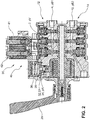
- the locking unit 30 comprises a locking valve 32 which is biased to the locked position and comprises a release chamber 34 (cf., also Fig. 2 ).
- the locking valve 32 in the embodiment shown in Fig. 2 is formed as a return-to-ride valve 33 which comprises a return-to-ride piston 35 seated within the release chamber 34.
- the general function of a return-to-ride valve is known in the art and will not be described in detail here.
- a suitable return-to-ride valve for example, is disclosed in EP 2 516 187 A1 .
- For unlocking the locking valve 32 it is necessary to supply the release chamber 34 with a pressure.
- the locking unit 30 moreover comprises an electromagnetic double valve arrangement 40 which is fluidly connected with the release chamber 34.
- the double valve arrangement 40 comprises a first control valve 41 and a second control valve 42. Both control valves 41, 42 are formed as 3/2-way valves.
- the first control valve 41 comprises a first control valve port 41.1 connected to the supply port 2, a second control valve port 41.2 connected to the release chamber 34 and a third control valve port 41.3 connected to the exhaust port 3.
- the second control valve 42 comprises a fourth control valve port 42.1 connected to the first bellows port 4, a fifth control valve port 42.2 connected to the release chamber 34, and a sixth control valve port 42.3 connected to the exhaust.
- Both, the first and the second control valves 41, 42 are spring biased into the first position which is shown in Fig. 1 , in which the second control valve port 41.2 is connected to the third control valve port 41.3 and the fifth control valve port 42.2 is connected with the sixth control valve port 42.3. In this manner, in the first position of the first and second control valves 41, 42, the release chamber 34 is supplied with ambient pressure.
- the first and the second control valves 41, 42 are connected to an electronic control unit ECU which might or might not be part of the valve device 1.
- the electronic control unit ECU provides a first switching signal S1 at the first control valve 41 and a second switching signal S2 at the second control valve 42. Both switching signals S1, S2 are identical, so that the first and the second control valves 41, 42 are switched simultaneously.
- the release chamber 34 is supplied with both, the supply pressure pV and the first bellows pressure pB1 which, in the driving position of the first lifting/lowering valve 12, is identical to the first levelling pressure pL1.
- the release pressure pR within the release chamber 34 is higher than the pressure which is supplied to the release chamber 34 when the first lifting/lowering valve 12 is in the lowering position.
- the release pressure pR only equals the supply pressure pV. Therefore, it is more difficult to switch the first lifting/lowering valve 12 from the lowering position to any other position than vice versa. Thus, stability of the valve device in total can be increased.
- valve device 1 comprises a check port 26 and a shutoff valve 50.
- the check port 26 can be used to check the second bellows pressure pB2, when the shutoff valve 50 is in the open position.
Landscapes
- Engineering & Computer Science (AREA)
- Mechanical Engineering (AREA)
- Multiple-Way Valves (AREA)
Description
- The invention relates to a valve device for an air suspension system in a vehicle, comprising a supply port for receiving a supply pressure, at least a first bellows port for providing a first bellows pressure, a first lifting/lowering valve manually operable by a hand lever and in fluid connection with the supply port and the first bellows port, wherein the hand lever is operable to selectively connect the first bellows port with the supply port for providing the first bellows pressure, and a locking unit for locking the position of the hand lever, the locking unit comprising a locking valve biased into the locking position and comprising a release chamber, wherein the locking valve is switchable into a release position upon a release pressure being supplied into the release chamber.
- Such valve devices are used to regulate the air volume in suspension bellows of an air suspension system. Thus, they regulate the level of the trailer with respect to the truck of the vehicle, towing the trailer. Increase and decrease of the air volume in the bellows is electronically controlled by an electronic control unit according to detected requirements. In addition thereto, it is necessary to manually regulate the air volume in the bellows, e.g. during loading and unloading the trailer, for e.g. adapting the level of the trailer with respect to a loading ramp. For achieving this, separate valve elements have been used in the past which are manually operable for lifting or lowering the trailer with respect to the truck. One such example is disclosed in
DE 10 2004 035 691 A1 - A further device is known from
EP 2 516 187 A1 - A still further device which comprises the features of the preamble of
claim 1 is disclosed inEP 2 540 537 A1 - Usually, for releasing the locking unit the supply pressure from the supply port is used. However, there are cases in which no supply pressure is delivered to the supply port, e.g. in cases when the respective trailer is parked. In such cases there is a problem to release the locking unit. In some cases, this is solved by an external pipe for delivering the required pressure. This may result in additional parts and a more expensive system. It is an objection of the invention to provide a valve device of the aforementioned type which is simplified and required less parts. Moreover it is a desire to increase safety and stability of the first lifting/lowering valve.
- According to the invention, the above-mentioned problem is solved by an electromagnetic double valve arrangement fluidly connected to the release chamber of the locking unit and being switchable between a first release position in which the release chamber is in fluid connection with an exhaust port and a second supply position in which the release chamber is in fluid connection with the supply port and the first bellows port. In former systems, the release chamber was only connectable to either the exhaust port or the supply port. According to the invention, now the release chamber is connectable to both, the supply port and the first bellows port, thus, the pressure in the release chamber is comprised of the supply pressure from the supply port and the first bellows pressure at the first bellows port. Thus, when the trailer is in the lowering position, the pressure in the release chamber will be much lower than in cases in which the trailer is in the lifting position.
- Moreover, in situations in which no supply pressure is supplied but rather ambient pressure is delivered at the supply port, still the locking unit can be released using the pressure from the first bellows port. Thus, even without supply pressure the locking unit can be released and the hand lever moved manually. The need for an external pipe is overcome by this solution.
- According to a first preferred embodiment, the electromagnetic double valve arrangement comprises a first control valve and a second control valve. For example, the first control valve can be used to provide the supply pressure into the release chamber, and the second control valve can be used to provide the pressure from the first bellows port to the release chamber. Both, the first and the second control valves, may be in principle of identical design, which could reduce costs.
- Preferably, the first control valve and the second control valve are switchable simultaneously. For example, the first and the second control valves are connected to the same electronic control unit which switches both valves simultaneously, or one signal is provided to both, the first and the second control valves. It is also contemplated that the first and the second control valves are integrated into one combined valve which has the first and the second control valves, so that they are switched simultaneously. For example, both, the first and the second control valves are switched when it is detected that the trailer exceeds a predetermined speed limit, e.g. 5 km/h.
- Preferably, the first control valve comprises a first control valve port connected to the supply port, a second control valve port connected to the release chamber and a third control valve port connected to the exhaust port. In a similar manner, the second control valve preferably comprises a fourth control valve port connected to the first bellows port, a fifth control valve port connected to the release chamber, and a sixth control valve port connected to the exhaust port. Both, the first and the second control valves, according to this embodiment, preferably are formed as 3/2-way valves. Preferably, both, the first and the second control valves are spring biased into a first position. In this first position, preferably the second control valve port is connected to the third control valve port, and the fifth control valve port is connected to the sixth control valve port. Thus, in this first position, the release chamber is connected to the exhaust and ambient pressure is supplied to the release chamber. Upon receipt of a respective signal, both, the first and the second control valves switch into the second position, in which the second control valve port preferably is connected to the first control valve port so that supply pressure is supplied to the release chamber. Also, the fifth control valve port is connected to the fourth control valve port, so that the first bellows pressure is supplied to the release chamber, also. Usually, when a trailer is transported on a railway vehicle, there is no electric supply to the trailer vehicle. Thus, the first and the second control valves are in the first position and release chamber is supplied with ambient pressure. The respective locking unit thus is locked and locks the position of the hand lever so that the first lifting/lowering valve does not switch into a driving or a lifting position.
- Preferably, the locking valve is or comprises a return-to-ride valve. A return-to-ride valve is usually used in such valve devices and on the one hand can block the position of the manually operable hand lever and on the other hand is able to bring back the first lifting/lowering valve into the driving position and also bring back the level of pressurized air in the bellows to the previous level when the hand lever is switched to the driving position manually. A suitable return-to-ride valve, for example, is disclosed in
EP 2 516 187 A1 - In a further preferred embodiment, the first lifting/lowering valve comprises a first lifting/lowering valve port connected to the first bellows port, a second lifting/lowering valve port connected to the exhaust port, a third lifting/lowering valve port connected to the supply port, and a fourth lifting/lowering valve port connected to a first levelling valve port. The first lifting/lowering valve preferably comprises at least three switching positions, namely a lowering position, a driving position and a lifting position. In the lowering position, the first bellows port shall be de-aerated, in the driving position, the first bellows port shall be at least partially aerated, and in the lifting position, the first bellows port shall be fully aerated. Thus, in a lowering position, the first lifting/lowering valve port is connected to the second lifting/lowering valve port, in a driving position, the first lifting/lowering valve port is connected to the fourth lifting/lowering valve port, and in a lifting position, the first lifting/lowering valve port is connected to the third lifting/lowering valve port. Thus, in the driving position, the first bellows port is connected to the first levelling valve port, which is used during to automatically realized the aerating and de-aerating function. Thus, the lifting/lowering valve (which is not part of the present invention) is connected to the first lifting/lowering valve port and supplies the respective bellows pressure to this port, which is then supplied via the first lifting/lowering valve to the first bellows port.
- Preferably, the valve device further comprises a second lifting/lowering valve for a second circuit. The second lifting/lowering valve is only optional, but for some applications, two air suspension circuits for the trailer are used. The second lifting/lowering valve may be switchable together with the first lifting/lowering valve, or may only be switchable manually.
- Preferably, the second lifting/lowering valve comprises a fifth lifting/lowering valve port connected to a second bellows port, a sixth lifting/lowering valve port connected to the exhaust port, a seventh lifting/lowering valve port connected to the supply port and an eighth lifting/lowering valve port connected to a second levelling valve port. In general, the first and the second lifting/lowering valves are identically formed and therefore reference is made to the above description for the first lifting/lowering valve.
- Also, the second lifting/lowering valve comprises a lowering position, a driving position and a lifting position. Preferably, in a lowering position of the second lifting/lowering valve, the first lifting/lowering valve port is connected to the sixth lifting/lowering valve port, in a driving position, the fifth lifting/lowering valve port is connected to the eighth lifting/lowering valve port, and in a lifting position, the fifth lifting/lowering valve port is connected to the seventh lifting/lowering valve port.
- Thus, the functions of the first and the second lifting/lowering valves are realized in the same time for both circuits. In case that one of the first and the second lifting/lowering valves has a failure, the second one of the first and second lifting/lowering valves may still carry out the respective functions.
- Moreover, it is preferred that the valve device comprises a check port and a shutoff valve for closing off the check port. The check port may be used to check pressure in the bellows by an operator. The shutoff valve preferably is biased into a closed position and may be electrically actuated by a respective signal.
- For a more complete understanding of the invention, the invention will now be described in detail with reference to the accompanying drawings. The detailed description will illustrate and describe what is considered as a preferred embodiment of the invention.
- It is therefore intended that the invention may not be limited to the exact form and detail shown and described herein, nor to anything less than the whole of the invention disclosed herein and as claimed herein after.
- In particular, any reference signs in the claims shall not be construed as limiting the scope of the invention. The wording "comprising" does not exclude other elements or steps. The word "a" or "an" does not exclude the plurality. The wording "a number of" items comprising also the
number 1, i.e. a single item, and further numbers like 2, 3, 4 and so forth. - In the accompanying drawings:
-
Fig. 1 shows a first layout of the valve device according to the invention; and -
Fig. 2 shows a cross section of a valve device according to the invention. - According to
Fig. 2 , avalve device 1 for an air suspension system in a trailer of a vehicle comprises asupply port 2 for receiving a supply pressure pV. The supply pressure pV may, for example, be supplied by a reservoir of the trailer which is not shown inFig. 1 . Thesupply port 2 may also be provided with a check valve, to prevent flow of air out of thevalve device 1 through thesupply port 2. Moreover, thevalve device 1 comprises anexhaust port 3 for de-aerating thevalve device 1. It shall be understood that also two or more exhaust ports can be provided, dependent on the respective design of the housing of thevalve device 1 and environmental constraints in the vehicle. - The
valve device 1 further comprises a first bellowsport 4 for providing a first bellows pressure pB1 to bellows of the air suspension system of the trailer. During a normal driving situation, the first bellows pressure pB1 usually is supplied via a firstlevelling valve port 6 which can be connected to a levelling valve (not shown). The levelling valve provides a first levelling pressure pL1 at the firstlevelling valve port 6. A levelling valve usually provides a respective levelling pressure during a driving situation which is automatically adjusted to a required height and level of the trailer. Thevalve device 1 according to the present invention receives the levelling pressure and guides it to the first bellowsport 4. - According to the present embodiment, the
valve device 1 further comprises a secondlevelling valve port 8 for receiving a second levelling pressure pL2, and a second bellowsport 10 for providing a second bellows pressure pB2. Thesecond levelling port 8 and the second bellowsport 10 are used for a second circuit guiding the second bellows pressure pB2 to the bellows of the trailer. Both, the first bellowsport 4 and the second bellowsport 10 are connected with the same bellows of the air suspension system. - The
valve device 1 comprises a first lifting/loweringvalve 12 and a second lifting/loweringvalve 14. The first lifting/loweringvalve 12 is provided for the first circuit and the first bellowsport 4 as well as the firstlevelling valve port 6. The second lifting/loweringvalve 14 accordingly is provided for the second circuit and thus for the secondlevelling valve port 8 and the second bellowsport 10. Both, the first and the second lifting/loweringvalves hand lever 20 which is manually operable to push the first and second lifting/loweringvalves - The first lifting/lowering
valve 12 comprises a first lifting/lowering valve port 12.1 which is connected to the first bellowsport 4. It further comprises a second lifting/lowering valve port 12.2 which is connected to theexhaust port 3. A third lifting/lowering valve port 12.3 is connected to thesupply port 2 and receives the supply pressure pV. A fourth lifting/lowering valve port 12.4 is connected to the firstlevelling valve port 6 and receives the first levelling pressure pL1. In this embodiment, the first lifting/loweringvalve 12 comprises five switching positions. The first switching position is a lowering position, the second switching position a stop position, the third switching position a drive position, the fourth switching position a stop position and the fifth switching position a lift position. In the first and the second stop positions, all ports are closed and no air may flow through the first lifting/loweringvalve 12. It shall be understood that the stop positions are only optional and could be left away in alternative embodiments. - In the lowering position, the first bellows
port 4 shall be de-aerated for lowering the trailer. Thus, in the lowering position, the first lifting/lowering valve port 12.1 is connected to the second lifting/lowering valve port 12.2, so that the first bellowsport 4 is connected with theexhaust 3. When the first lifting/loweringvalve 12 is pushed into the driving position, the fourth lifting/lowering valve port 12.4 is connected with the first lifting/lowering valve port 12.1. In this position, the firstlevelling valve port 6 is connected to the first bellowsport 4 and thus the first levelling pressure pL1 is supplied at the first bellowsport 4 to provide the first bellows pressure pB1. In the lifting position, the first bellowsport 4 will be aerated fully and thus, the first lifting/lowering valve port 12.1 is connected with the third lifting/lowering valve port 12.3, so that supply pressure pV is provided at the first bellowsport 4. - In the same manner, the second lifting/lowering
valve 14 comprises a fifth lifting/lowering valve port 14.1 which is connected with the second bellowsport 10. A sixth lifting/lowering valve port 14.2 is connected to theexhaust 3. A seventh lifting/lowering valve port 14.3 is connected with thesupply port 2 for receiving the supply pressure pV, and an eighth lifting/lowering valve port 14.4 is connected to the secondlevelling valve port 8. Again, in the lowering position, the fifth lifting/lowering valve port 14.1 is connected with the sixth lifting/lowering valve port 14.2, so that the second bellowsport 10 is connected with the exhaust and ambient pressure is supplied at the second bellowsport 10. In the drive position, the fifth lifting/lowering valve port 14.1 is connected with the eighth lifting/lowering valve port 14.4, so that the second levelling pressure pL2, which might be identical to the first levelling pressure pL1, is supplied via the secondlevelling valve port 8, the second lifting/loweringvalve 14 at the second bellowsport 10. In the lifting position, the fifth lifting/lowering valve port 14.1 is connected with the seventh lifting/lowering valve port 14.3, so that the supply pressure pV is provided at the second bellowsport 10. - For locking the
hand lever 20 in the respective position, a lockingunit 30 is provided. The lockingunit 30 comprises a locking valve 32 which is biased to the locked position and comprises a release chamber 34 (cf., alsoFig. 2 ). The locking valve 32 in the embodiment shown inFig. 2 is formed as a return-to-ride valve 33 which comprises a return-to-ride piston 35 seated within the release chamber 34. The general function of a return-to-ride valve is known in the art and will not be described in detail here. A suitable return-to-ride valve, for example, is disclosed inEP 2 516 187 A1spring 36, however is very difficult. Pressure within the release chamber 34 will lead to lifting the return-to-ride piston 35 with respect toFig. 2 and thus opens the locking valve 32. - The locking
unit 30 according to this embodiment moreover comprises an electromagneticdouble valve arrangement 40 which is fluidly connected with the release chamber 34. Thedouble valve arrangement 40 comprises afirst control valve 41 and asecond control valve 42. Bothcontrol valves first control valve 41 comprises a first control valve port 41.1 connected to thesupply port 2, a second control valve port 41.2 connected to the release chamber 34 and a third control valve port 41.3 connected to theexhaust port 3. Thesecond control valve 42 comprises a fourth control valve port 42.1 connected to the first bellowsport 4, a fifth control valve port 42.2 connected to the release chamber 34, and a sixth control valve port 42.3 connected to the exhaust. Both, the first and thesecond control valves Fig. 1 , in which the second control valve port 41.2 is connected to the third control valve port 41.3 and the fifth control valve port 42.2 is connected with the sixth control valve port 42.3. In this manner, in the first position of the first andsecond control valves - The first and the
second control valves valve device 1. The electronic control unit ECU provides a first switching signal S1 at thefirst control valve 41 and a second switching signal S2 at thesecond control valve 42. Both switching signals S1, S2 are identical, so that the first and thesecond control valves valve 12, is identical to the first levelling pressure pL1. - Thus, when the first lifting/lowering
valve 12 is either in the drive position or the lifting position, the release pressure pR within the release chamber 34 is higher than the pressure which is supplied to the release chamber 34 when the first lifting/loweringvalve 12 is in the lowering position. In the lowering position, the release pressure pR only equals the supply pressure pV. Therefore, it is more difficult to switch the first lifting/loweringvalve 12 from the lowering position to any other position than vice versa. Thus, stability of the valve device in total can be increased. - Additionally, the
valve device 1 comprises acheck port 26 and ashutoff valve 50. Thecheck port 26 can be used to check the second bellows pressure pB2, when theshutoff valve 50 is in the open position. -
- 1
- Valve device
- 2
- Supply port
- 3
- Exhaust port
- 4
- first bellows port
- 6
- First leveling valve port
- 8
- second leveling valve port
- 10
- second bellows port
- 12
- first lifting/lowering valve
- 12.1
- first lifting/lowering valve port
- 12.2
- second lifting/lowering valve port
- 12.3
- third lifting/lowering valve port
- 12.4
- fourth lifting/lowering valve port
- 14
- second lifting/lowering valve
- 14.1
- fifth lifting/lowering valve port
- 14.2
- sixth lifting/lowering valve port
- 14.3
- seventh lifting/lowering valve port
- 14.4
- eights lifting/lowering valve port
- 20
- Hand lever
- 30
- locking unit
- 32
- locking valve
- 33
- Return to ride valve
- 34
- Release chamber
- 35
- Return to ride piston
- 40
- Electromagnetic double valve arrangement
- 41
- First control valve
- 41.1
- First control valve port
- 41.2
- second control valve port
- 41.3
- third control valve port
- 42
- second control valve
- 42.1
- fourth control valve port
- 42.2
- fifth control valve port
- 42.3
- sixth control valve port
- 50
- shutoff valve
- ECU
- Electronic control unit
- pB1
- first bellows pressure
- pB2
- second bellows pressure
- pL1
- First leveling pressure
- pL2
- second leveling pressure
- pR
- Release pressure
- pV
- Supply pressure
- S1
- First switching signal
- S2
- second switching signal
Claims (11)
- A valve device (1) for an air suspension system in a trailer of a vehicle, said valve device comprising:a supply port (2) for receiving a supply pressure (pV),at least a first bellows port (4) for providing a first bellows pressure (pB1),a first lifting/lowering valve (12) manually operable by a hand lever (20) and in fluid connection with the supply port (2) and the first bellows port (4), wherein the hand lever (20) is operable to selectively connect the first bellows port (4) with the supply port (2) for providing the first bellows pressure (pB1), anda locking unit (30) for locking the position of the hand lever (20), the locking unit (30) comprising a locking valve (32) biased into the locked position and comprising a release chamber (34), wherein the locking valve (32) is switchable into a release position upon a release pressure (pR) being supplied into the release chamber (34),characterized by an electromagnetic double valve arrangement (40) fluidly connected to the release chamber (34) and being switchable between a first release position, in which the release chamber (34) is in fluid connection with an exhaust port (3), and a second supply position, in which the release chamber (34) is in fluid connection with the supply port (2) and the first bellows port (4).
- The valve device (1) according to claim 1, wherein the electromagnetic double valve arrangement (40) comprises a first control valve (41) and a second control valve (42).
- The valve device (1) according to claim 2, wherein the first control valve (41) and the second control valve (42) are switchable simultaneously.
- The valve device (1) according to any of the preceding claims 2 or 3, wherein
the first control valve (41) comprises a first control valve port (41.1) connected to the supply port (2), a second control valve port (41.2) connected to the release chamber (34), and a third control valve port (41.3) connected to the exhaust port (3), and wherein
the second control valve (42) comprises a fourth control valve port (42.1) connected to the first bellows port (4), a fifth control valve port (42.2) connected to the release chamber (34), and a sixth control valve port (42.3) connected to the exhaust port (3). - The valve device (1) according to any of the preceding claims, wherein the locking valve (32) is or comprises a return-to-ride valve.
- The valve device (1) according to any of the preceding claims, wherein the first lifting/lowering valve (12) comprises a first lifting/lowering valve port (12.1) connected to the first bellows port (4), a second lifting/lowering valve port (12.2) connected to the exhaust port (3), a third lifting/lowering valve port (12.3) connected to the supply port (2), and a fourth lifting/lowering valve port (12.4) connected to a first leveling valve port (6).
- The valve device (1) according to claim 6, wherein in a lowering position of the first lifting/lowering valve (12) the first lifting/lowering valve port (12.1) is connected to the second lifting/lowering valve port (12.2), in a driving position the first lifting/lowering valve port (12.1) is connected to the fourth lifting/lowering valve port (12.4), and in a lifting position the first lifting/lowering valve port (12.1) is connected to the third lifting/lowering valve port (12.3).
- The valve device (1) according to any of the preceding claims, comprising a second lifting/lowering valve (14) for a second circuit.
- The valve device (1) according to claim 8, wherein the second lifting/lowering valve (14) comprises a fifth lifting/lowering valve port (14.1) connected to a second bellows port (10), a sixth lifting/lowering valve port (14.2) connected to the exhaust port (3), a seventh lifting/lowering valve port (14.3) connected to the supply port (2) and an eighth lifting/lowering valve port (14.4) connected to a second leveling valve port (8).
- The valve device (1) according to claim 9, wherein in a lowering position of the second lifting/lowering valve (14) the fifth lifting/lowering valve port (14.1) is connected to the sixth lifting/lowering valve port (14.2), in a driving position the fifth lifting/lowering valve port (14.1) is connected to the eighth lifting/lowering valve port (14.4), and in a lifting position the fifth lifting/lowering valve port (14.1) is connected to the seventh lifting/lowering valve port (14.3).
- The valve device (1) according to any of the preceding claims, comprising a check port (26) and a shut-off valve (50) for closing off the check port (26).
Priority Applications (1)
| Application Number | Priority Date | Filing Date | Title |
|---|---|---|---|
| EP18202835.7A EP3643543B1 (en) | 2018-10-26 | 2018-10-26 | Double solenoid in trailer air suspension control device |
Applications Claiming Priority (1)
| Application Number | Priority Date | Filing Date | Title |
|---|---|---|---|
| EP18202835.7A EP3643543B1 (en) | 2018-10-26 | 2018-10-26 | Double solenoid in trailer air suspension control device |
Publications (2)
| Publication Number | Publication Date |
|---|---|
| EP3643543A1 EP3643543A1 (en) | 2020-04-29 |
| EP3643543B1 true EP3643543B1 (en) | 2021-06-30 |
Family
ID=64051394
Family Applications (1)
| Application Number | Title | Priority Date | Filing Date |
|---|---|---|---|
| EP18202835.7A Active EP3643543B1 (en) | 2018-10-26 | 2018-10-26 | Double solenoid in trailer air suspension control device |
Country Status (1)
| Country | Link |
|---|---|
| EP (1) | EP3643543B1 (en) |
Cited By (1)
| Publication number | Priority date | Publication date | Assignee | Title |
|---|---|---|---|---|
| EP4209367A1 (en) | 2022-01-07 | 2023-07-12 | ZF CV Systems Europe BV | Method for triggering an rtr valve, control device, air spring system and trailer |
Family Cites Families (4)
| Publication number | Priority date | Publication date | Assignee | Title |
|---|---|---|---|---|
| DE102004035691B4 (en) | 2003-11-19 | 2021-04-29 | Zf Cv Systems Hannover Gmbh | Air suspension device for a vehicle |
| DE102004028325B4 (en) * | 2004-06-11 | 2006-04-27 | Knorr-Bremse Systeme für Nutzfahrzeuge GmbH | Air suspension device for vehicles, in particular for commercial vehicles |
| DE102010011431A1 (en) | 2009-12-23 | 2011-06-30 | WABCO GmbH, 30453 | Valve device for an air suspension system |
| DE102011051503B4 (en) | 2011-07-01 | 2014-09-04 | Haldex Brake Products Gmbh | Air suspension system for a commercial vehicle |
-
2018
- 2018-10-26 EP EP18202835.7A patent/EP3643543B1/en active Active
Cited By (2)
| Publication number | Priority date | Publication date | Assignee | Title |
|---|---|---|---|---|
| EP4209367A1 (en) | 2022-01-07 | 2023-07-12 | ZF CV Systems Europe BV | Method for triggering an rtr valve, control device, air spring system and trailer |
| DE102022100288A1 (en) | 2022-01-07 | 2023-07-13 | Zf Cv Systems Europe Bv | Procedure for triggering an RtR valve, control unit, air suspension system and trailer |
Also Published As
| Publication number | Publication date |
|---|---|
| EP3643543A1 (en) | 2020-04-29 |
Similar Documents
| Publication | Publication Date | Title |
|---|---|---|
| CN110431054B (en) | Electropneumatic control module and tractor | |
| CN100482487C (en) | Pneumatic suspension unit for a vehicle | |
| US20230347857A1 (en) | Vehicle braking system | |
| CN111032457B (en) | Parking brake valve device | |
| CN111032456B (en) | Electropneumatic trailer supply module for providing a trailer supply pressure | |
| CN110997434B (en) | Electropneumatic parking brake module with directly controlled valve | |
| US7331592B2 (en) | Compressed air processing apparatus for compressed air systems of motor vehicles | |
| CN110461672B (en) | Integrated trailer control module (TCV) with external electropneumatic hand brake unit (EPH) | |
| CN107921941B (en) | Electric parking brake device with additional energy supply | |
| CN111163985B (en) | Parking brake valve device | |
| CN111465520A (en) | Compressed air supply system, method and vehicle for operating a pneumatic system | |
| CN111448397B (en) | Compressed air supply device, method and vehicle for operating a pneumatic device | |
| CN105324284B (en) | For the control device for the brake for controlling tractor-trailer combination | |
| CN114650938A (en) | Electronic pneumatic control module | |
| EP3643543B1 (en) | Double solenoid in trailer air suspension control device | |
| CN112313126A (en) | Parking brake device for a motor vehicle | |
| US7097192B2 (en) | Trailer slider locking pin interlock with parking brake | |
| CN112088115A (en) | Redundant brake unit for a brake system and system using the same | |
| CN105452076A (en) | Electro-pneumatic parking brake assembly | |
| CN114248738A (en) | Compressed air device for trailer | |
| US6609767B2 (en) | Pneumatic control system | |
| CN105984364B (en) | Redundant control electric control gas circuit hydraulic valve and system for dumper | |
| RU2635732C1 (en) | Railroad vehicle driver's brake valve | |
| CN117597279A (en) | Electro-pneumatic valve installation with self-retaining safety valve | |
| CN114761295A (en) | Anti-failure valve unit for parking brake function and parking brake valve facility |
Legal Events
| Date | Code | Title | Description |
|---|---|---|---|
| PUAI | Public reference made under article 153(3) epc to a published international application that has entered the european phase |
Free format text: ORIGINAL CODE: 0009012 |
|
| STAA | Information on the status of an ep patent application or granted ep patent |
Free format text: STATUS: THE APPLICATION HAS BEEN PUBLISHED |
|
| AK | Designated contracting states |
Kind code of ref document: A1 Designated state(s): AL AT BE BG CH CY CZ DE DK EE ES FI FR GB GR HR HU IE IS IT LI LT LU LV MC MK MT NL NO PL PT RO RS SE SI SK SM TR |
|
| AX | Request for extension of the european patent |
Extension state: BA ME |
|
| STAA | Information on the status of an ep patent application or granted ep patent |
Free format text: STATUS: REQUEST FOR EXAMINATION WAS MADE |
|
| 17P | Request for examination filed |
Effective date: 20201029 |
|
| RBV | Designated contracting states (corrected) |
Designated state(s): AL AT BE BG CH CY CZ DE DK EE ES FI FR GB GR HR HU IE IS IT LI LT LU LV MC MK MT NL NO PL PT RO RS SE SI SK SM TR |
|
| GRAP | Despatch of communication of intention to grant a patent |
Free format text: ORIGINAL CODE: EPIDOSNIGR1 |
|
| STAA | Information on the status of an ep patent application or granted ep patent |
Free format text: STATUS: GRANT OF PATENT IS INTENDED |
|
| GRAS | Grant fee paid |
Free format text: ORIGINAL CODE: EPIDOSNIGR3 |
|
| INTG | Intention to grant announced |
Effective date: 20210428 |
|
| RAP3 | Party data changed (applicant data changed or rights of an application transferred) |
Owner name: ZF CV SYSTEMS EUROPE BV |
|
| GRAA | (expected) grant |
Free format text: ORIGINAL CODE: 0009210 |
|
| STAA | Information on the status of an ep patent application or granted ep patent |
Free format text: STATUS: THE PATENT HAS BEEN GRANTED |
|
| AK | Designated contracting states |
Kind code of ref document: B1 Designated state(s): AL AT BE BG CH CY CZ DE DK EE ES FI FR GB GR HR HU IE IS IT LI LT LU LV MC MK MT NL NO PL PT RO RS SE SI SK SM TR |
|
| REG | Reference to a national code |
Ref country code: CH Ref legal event code: EP |
|
| REG | Reference to a national code |
Ref country code: AT Ref legal event code: REF Ref document number: 1406037 Country of ref document: AT Kind code of ref document: T Effective date: 20210715 |
|
| REG | Reference to a national code |
Ref country code: DE Ref legal event code: R096 Ref document number: 602018019271 Country of ref document: DE |
|
| REG | Reference to a national code |
Ref country code: IE Ref legal event code: FG4D |
|
| REG | Reference to a national code |
Ref country code: LT Ref legal event code: MG9D |
|
| PG25 | Lapsed in a contracting state [announced via postgrant information from national office to epo] |
Ref country code: BG Free format text: LAPSE BECAUSE OF FAILURE TO SUBMIT A TRANSLATION OF THE DESCRIPTION OR TO PAY THE FEE WITHIN THE PRESCRIBED TIME-LIMIT Effective date: 20210930 Ref country code: FI Free format text: LAPSE BECAUSE OF FAILURE TO SUBMIT A TRANSLATION OF THE DESCRIPTION OR TO PAY THE FEE WITHIN THE PRESCRIBED TIME-LIMIT Effective date: 20210630 Ref country code: HR Free format text: LAPSE BECAUSE OF FAILURE TO SUBMIT A TRANSLATION OF THE DESCRIPTION OR TO PAY THE FEE WITHIN THE PRESCRIBED TIME-LIMIT Effective date: 20210630 |
|
| REG | Reference to a national code |
Ref country code: NL Ref legal event code: MP Effective date: 20210630 |
|
| REG | Reference to a national code |
Ref country code: AT Ref legal event code: MK05 Ref document number: 1406037 Country of ref document: AT Kind code of ref document: T Effective date: 20210630 |
|
| PG25 | Lapsed in a contracting state [announced via postgrant information from national office to epo] |
Ref country code: GR Free format text: LAPSE BECAUSE OF FAILURE TO SUBMIT A TRANSLATION OF THE DESCRIPTION OR TO PAY THE FEE WITHIN THE PRESCRIBED TIME-LIMIT Effective date: 20211001 Ref country code: NO Free format text: LAPSE BECAUSE OF FAILURE TO SUBMIT A TRANSLATION OF THE DESCRIPTION OR TO PAY THE FEE WITHIN THE PRESCRIBED TIME-LIMIT Effective date: 20210930 Ref country code: LV Free format text: LAPSE BECAUSE OF FAILURE TO SUBMIT A TRANSLATION OF THE DESCRIPTION OR TO PAY THE FEE WITHIN THE PRESCRIBED TIME-LIMIT Effective date: 20210630 Ref country code: SE Free format text: LAPSE BECAUSE OF FAILURE TO SUBMIT A TRANSLATION OF THE DESCRIPTION OR TO PAY THE FEE WITHIN THE PRESCRIBED TIME-LIMIT Effective date: 20210630 Ref country code: RS Free format text: LAPSE BECAUSE OF FAILURE TO SUBMIT A TRANSLATION OF THE DESCRIPTION OR TO PAY THE FEE WITHIN THE PRESCRIBED TIME-LIMIT Effective date: 20210630 |
|
| PG25 | Lapsed in a contracting state [announced via postgrant information from national office to epo] |
Ref country code: ES Free format text: LAPSE BECAUSE OF FAILURE TO SUBMIT A TRANSLATION OF THE DESCRIPTION OR TO PAY THE FEE WITHIN THE PRESCRIBED TIME-LIMIT Effective date: 20210630 Ref country code: EE Free format text: LAPSE BECAUSE OF FAILURE TO SUBMIT A TRANSLATION OF THE DESCRIPTION OR TO PAY THE FEE WITHIN THE PRESCRIBED TIME-LIMIT Effective date: 20210630 Ref country code: SK Free format text: LAPSE BECAUSE OF FAILURE TO SUBMIT A TRANSLATION OF THE DESCRIPTION OR TO PAY THE FEE WITHIN THE PRESCRIBED TIME-LIMIT Effective date: 20210630 Ref country code: SM Free format text: LAPSE BECAUSE OF FAILURE TO SUBMIT A TRANSLATION OF THE DESCRIPTION OR TO PAY THE FEE WITHIN THE PRESCRIBED TIME-LIMIT Effective date: 20210630 Ref country code: AT Free format text: LAPSE BECAUSE OF FAILURE TO SUBMIT A TRANSLATION OF THE DESCRIPTION OR TO PAY THE FEE WITHIN THE PRESCRIBED TIME-LIMIT Effective date: 20210630 Ref country code: CZ Free format text: LAPSE BECAUSE OF FAILURE TO SUBMIT A TRANSLATION OF THE DESCRIPTION OR TO PAY THE FEE WITHIN THE PRESCRIBED TIME-LIMIT Effective date: 20210630 Ref country code: NL Free format text: LAPSE BECAUSE OF FAILURE TO SUBMIT A TRANSLATION OF THE DESCRIPTION OR TO PAY THE FEE WITHIN THE PRESCRIBED TIME-LIMIT Effective date: 20210630 Ref country code: PT Free format text: LAPSE BECAUSE OF FAILURE TO SUBMIT A TRANSLATION OF THE DESCRIPTION OR TO PAY THE FEE WITHIN THE PRESCRIBED TIME-LIMIT Effective date: 20211102 Ref country code: RO Free format text: LAPSE BECAUSE OF FAILURE TO SUBMIT A TRANSLATION OF THE DESCRIPTION OR TO PAY THE FEE WITHIN THE PRESCRIBED TIME-LIMIT Effective date: 20210630 |
|
| PG25 | Lapsed in a contracting state [announced via postgrant information from national office to epo] |
Ref country code: PL Free format text: LAPSE BECAUSE OF FAILURE TO SUBMIT A TRANSLATION OF THE DESCRIPTION OR TO PAY THE FEE WITHIN THE PRESCRIBED TIME-LIMIT Effective date: 20210630 |
|
| REG | Reference to a national code |
Ref country code: DE Ref legal event code: R097 Ref document number: 602018019271 Country of ref document: DE |
|
| PG25 | Lapsed in a contracting state [announced via postgrant information from national office to epo] |
Ref country code: DK Free format text: LAPSE BECAUSE OF FAILURE TO SUBMIT A TRANSLATION OF THE DESCRIPTION OR TO PAY THE FEE WITHIN THE PRESCRIBED TIME-LIMIT Effective date: 20210630 |
|
| PLBE | No opposition filed within time limit |
Free format text: ORIGINAL CODE: 0009261 |
|
| STAA | Information on the status of an ep patent application or granted ep patent |
Free format text: STATUS: NO OPPOSITION FILED WITHIN TIME LIMIT |
|
| REG | Reference to a national code |
Ref country code: CH Ref legal event code: PL |
|
| PG25 | Lapsed in a contracting state [announced via postgrant information from national office to epo] |
Ref country code: AL Free format text: LAPSE BECAUSE OF FAILURE TO SUBMIT A TRANSLATION OF THE DESCRIPTION OR TO PAY THE FEE WITHIN THE PRESCRIBED TIME-LIMIT Effective date: 20210630 |
|
| 26N | No opposition filed |
Effective date: 20220331 |
|
| REG | Reference to a national code |
Ref country code: BE Ref legal event code: MM Effective date: 20211031 |
|
| PG25 | Lapsed in a contracting state [announced via postgrant information from national office to epo] |
Ref country code: MC Free format text: LAPSE BECAUSE OF FAILURE TO SUBMIT A TRANSLATION OF THE DESCRIPTION OR TO PAY THE FEE WITHIN THE PRESCRIBED TIME-LIMIT Effective date: 20210630 |
|
| PG25 | Lapsed in a contracting state [announced via postgrant information from national office to epo] |
Ref country code: LU Free format text: LAPSE BECAUSE OF NON-PAYMENT OF DUE FEES Effective date: 20211026 Ref country code: IT Free format text: LAPSE BECAUSE OF FAILURE TO SUBMIT A TRANSLATION OF THE DESCRIPTION OR TO PAY THE FEE WITHIN THE PRESCRIBED TIME-LIMIT Effective date: 20210630 Ref country code: BE Free format text: LAPSE BECAUSE OF NON-PAYMENT OF DUE FEES Effective date: 20211031 |
|
| PG25 | Lapsed in a contracting state [announced via postgrant information from national office to epo] |
Ref country code: LI Free format text: LAPSE BECAUSE OF NON-PAYMENT OF DUE FEES Effective date: 20211031 Ref country code: CH Free format text: LAPSE BECAUSE OF NON-PAYMENT OF DUE FEES Effective date: 20211031 |
|
| PG25 | Lapsed in a contracting state [announced via postgrant information from national office to epo] |
Ref country code: IE Free format text: LAPSE BECAUSE OF NON-PAYMENT OF DUE FEES Effective date: 20211026 |
|
| PGFP | Annual fee paid to national office [announced via postgrant information from national office to epo] |
Ref country code: FR Payment date: 20221020 Year of fee payment: 5 |
|
| PGFP | Annual fee paid to national office [announced via postgrant information from national office to epo] |
Ref country code: GB Payment date: 20221024 Year of fee payment: 5 |
|
| PG25 | Lapsed in a contracting state [announced via postgrant information from national office to epo] |
Ref country code: LT Free format text: LAPSE BECAUSE OF FAILURE TO SUBMIT A TRANSLATION OF THE DESCRIPTION OR TO PAY THE FEE WITHIN THE PRESCRIBED TIME-LIMIT Effective date: 20210630 |
|
| PG25 | Lapsed in a contracting state [announced via postgrant information from national office to epo] |
Ref country code: CY Free format text: LAPSE BECAUSE OF FAILURE TO SUBMIT A TRANSLATION OF THE DESCRIPTION OR TO PAY THE FEE WITHIN THE PRESCRIBED TIME-LIMIT Effective date: 20210630 |
|
| P01 | Opt-out of the competence of the unified patent court (upc) registered |
Effective date: 20230528 |
|
| PG25 | Lapsed in a contracting state [announced via postgrant information from national office to epo] |
Ref country code: HU Free format text: LAPSE BECAUSE OF FAILURE TO SUBMIT A TRANSLATION OF THE DESCRIPTION OR TO PAY THE FEE WITHIN THE PRESCRIBED TIME-LIMIT; INVALID AB INITIO Effective date: 20181026 |
|
| PGFP | Annual fee paid to national office [announced via postgrant information from national office to epo] |
Ref country code: DE Payment date: 20230830 Year of fee payment: 6 |
|
| PG25 | Lapsed in a contracting state [announced via postgrant information from national office to epo] |
Ref country code: MK Free format text: LAPSE BECAUSE OF FAILURE TO SUBMIT A TRANSLATION OF THE DESCRIPTION OR TO PAY THE FEE WITHIN THE PRESCRIBED TIME-LIMIT Effective date: 20210630 |
|
| GBPC | Gb: european patent ceased through non-payment of renewal fee |
Effective date: 20231026 |
|
| PG25 | Lapsed in a contracting state [announced via postgrant information from national office to epo] |
Ref country code: TR Free format text: LAPSE BECAUSE OF FAILURE TO SUBMIT A TRANSLATION OF THE DESCRIPTION OR TO PAY THE FEE WITHIN THE PRESCRIBED TIME-LIMIT Effective date: 20210630 |
|
| PG25 | Lapsed in a contracting state [announced via postgrant information from national office to epo] |
Ref country code: GB Free format text: LAPSE BECAUSE OF NON-PAYMENT OF DUE FEES Effective date: 20231026 |
|
| PG25 | Lapsed in a contracting state [announced via postgrant information from national office to epo] |
Ref country code: GB Free format text: LAPSE BECAUSE OF NON-PAYMENT OF DUE FEES Effective date: 20231026 Ref country code: FR Free format text: LAPSE BECAUSE OF NON-PAYMENT OF DUE FEES Effective date: 20231031 |