EP3643342B1 - Interface device for carrying out haemodialysis - Google Patents
Interface device for carrying out haemodialysis Download PDFInfo
- Publication number
- EP3643342B1 EP3643342B1 EP19205183.7A EP19205183A EP3643342B1 EP 3643342 B1 EP3643342 B1 EP 3643342B1 EP 19205183 A EP19205183 A EP 19205183A EP 3643342 B1 EP3643342 B1 EP 3643342B1
- Authority
- EP
- European Patent Office
- Prior art keywords
- port
- interface device
- venous
- arterial
- configuration
- Prior art date
- Legal status (The legal status is an assumption and is not a legal conclusion. Google has not performed a legal analysis and makes no representation as to the accuracy of the status listed.)
- Active
Links
- 238000001631 haemodialysis Methods 0.000 title claims description 129
- 230000000322 hemodialysis Effects 0.000 claims description 128
- 239000012530 fluid Substances 0.000 claims description 83
- 239000008280 blood Substances 0.000 claims description 64
- 210000004369 blood Anatomy 0.000 claims description 64
- 239000007788 liquid Substances 0.000 claims description 41
- 238000004891 communication Methods 0.000 claims description 21
- 230000007246 mechanism Effects 0.000 claims description 11
- 238000012546 transfer Methods 0.000 claims description 11
- 239000007924 injection Substances 0.000 description 10
- 238000002347 injection Methods 0.000 description 10
- 239000007789 gas Substances 0.000 description 7
- 239000012528 membrane Substances 0.000 description 7
- 238000011109 contamination Methods 0.000 description 6
- 210000002966 serum Anatomy 0.000 description 6
- 230000008859 change Effects 0.000 description 5
- 239000003814 drug Substances 0.000 description 5
- 229940079593 drug Drugs 0.000 description 5
- 235000021183 entrée Nutrition 0.000 description 5
- 238000001514 detection method Methods 0.000 description 4
- 238000011049 filling Methods 0.000 description 4
- 238000011084 recovery Methods 0.000 description 4
- 238000000034 method Methods 0.000 description 3
- 230000002093 peripheral effect Effects 0.000 description 3
- 238000007789 sealing Methods 0.000 description 3
- 238000012550 audit Methods 0.000 description 2
- 230000000295 complement effect Effects 0.000 description 2
- 208000015181 infectious disease Diseases 0.000 description 2
- 238000005259 measurement Methods 0.000 description 2
- 230000000474 nursing effect Effects 0.000 description 2
- 239000002504 physiological saline solution Substances 0.000 description 2
- 239000000243 solution Substances 0.000 description 2
- 210000001519 tissue Anatomy 0.000 description 2
- 206010003226 Arteriovenous fistula Diseases 0.000 description 1
- 241000287107 Passer Species 0.000 description 1
- 239000004696 Poly ether ether ketone Substances 0.000 description 1
- 230000002421 anti-septic effect Effects 0.000 description 1
- 239000003146 anticoagulant agent Substances 0.000 description 1
- 229940127219 anticoagulant drug Drugs 0.000 description 1
- 238000013475 authorization Methods 0.000 description 1
- JUPQTSLXMOCDHR-UHFFFAOYSA-N benzene-1,4-diol;bis(4-fluorophenyl)methanone Chemical compound OC1=CC=C(O)C=C1.C1=CC(F)=CC=C1C(=O)C1=CC=C(F)C=C1 JUPQTSLXMOCDHR-UHFFFAOYSA-N 0.000 description 1
- 239000000470 constituent Substances 0.000 description 1
- 230000008878 coupling Effects 0.000 description 1
- 238000010168 coupling process Methods 0.000 description 1
- 238000005859 coupling reaction Methods 0.000 description 1
- -1 dialysate Substances 0.000 description 1
- 238000000502 dialysis Methods 0.000 description 1
- 230000000694 effects Effects 0.000 description 1
- 239000007943 implant Substances 0.000 description 1
- 238000002513 implantation Methods 0.000 description 1
- 239000012535 impurity Substances 0.000 description 1
- 238000003780 insertion Methods 0.000 description 1
- 230000037431 insertion Effects 0.000 description 1
- 238000002955 isolation Methods 0.000 description 1
- 238000004519 manufacturing process Methods 0.000 description 1
- 238000013508 migration Methods 0.000 description 1
- 230000005012 migration Effects 0.000 description 1
- 230000002572 peristaltic effect Effects 0.000 description 1
- 229920002530 polyetherether ketone Polymers 0.000 description 1
- 229920001296 polysiloxane Polymers 0.000 description 1
- 229920002635 polyurethane Polymers 0.000 description 1
- 239000004814 polyurethane Substances 0.000 description 1
- 238000002360 preparation method Methods 0.000 description 1
- 238000012545 processing Methods 0.000 description 1
- 238000000746 purification Methods 0.000 description 1
- 230000002441 reversible effect Effects 0.000 description 1
- 239000000126 substance Substances 0.000 description 1
- 229920001169 thermoplastic Polymers 0.000 description 1
- 239000004416 thermosoftening plastic Substances 0.000 description 1
- XLYOFNOQVPJJNP-UHFFFAOYSA-N water Substances O XLYOFNOQVPJJNP-UHFFFAOYSA-N 0.000 description 1
Images


Classifications
-
- A—HUMAN NECESSITIES
- A61—MEDICAL OR VETERINARY SCIENCE; HYGIENE
- A61M—DEVICES FOR INTRODUCING MEDIA INTO, OR ONTO, THE BODY; DEVICES FOR TRANSDUCING BODY MEDIA OR FOR TAKING MEDIA FROM THE BODY; DEVICES FOR PRODUCING OR ENDING SLEEP OR STUPOR
- A61M1/00—Suction or pumping devices for medical purposes; Devices for carrying-off, for treatment of, or for carrying-over, body-liquids; Drainage systems
- A61M1/36—Other treatment of blood in a by-pass of the natural circulatory system, e.g. temperature adaptation, irradiation ; Extra-corporeal blood circuits
- A61M1/3621—Extra-corporeal blood circuits
- A61M1/3653—Interfaces between patient blood circulation and extra-corporal blood circuit
- A61M1/3659—Cannulae pertaining to extracorporeal circulation
- A61M1/3661—Cannulae pertaining to extracorporeal circulation for haemodialysis
-
- A—HUMAN NECESSITIES
- A61—MEDICAL OR VETERINARY SCIENCE; HYGIENE
- A61M—DEVICES FOR INTRODUCING MEDIA INTO, OR ONTO, THE BODY; DEVICES FOR TRANSDUCING BODY MEDIA OR FOR TAKING MEDIA FROM THE BODY; DEVICES FOR PRODUCING OR ENDING SLEEP OR STUPOR
- A61M1/00—Suction or pumping devices for medical purposes; Devices for carrying-off, for treatment of, or for carrying-over, body-liquids; Drainage systems
- A61M1/36—Other treatment of blood in a by-pass of the natural circulatory system, e.g. temperature adaptation, irradiation ; Extra-corporeal blood circuits
- A61M1/3621—Extra-corporeal blood circuits
- A61M1/3653—Interfaces between patient blood circulation and extra-corporal blood circuit
-
- A—HUMAN NECESSITIES
- A61—MEDICAL OR VETERINARY SCIENCE; HYGIENE
- A61M—DEVICES FOR INTRODUCING MEDIA INTO, OR ONTO, THE BODY; DEVICES FOR TRANSDUCING BODY MEDIA OR FOR TAKING MEDIA FROM THE BODY; DEVICES FOR PRODUCING OR ENDING SLEEP OR STUPOR
- A61M1/00—Suction or pumping devices for medical purposes; Devices for carrying-off, for treatment of, or for carrying-over, body-liquids; Drainage systems
- A61M1/14—Dialysis systems; Artificial kidneys; Blood oxygenators ; Reciprocating systems for treatment of body fluids, e.g. single needle systems for hemofiltration or pheresis
- A61M1/16—Dialysis systems; Artificial kidneys; Blood oxygenators ; Reciprocating systems for treatment of body fluids, e.g. single needle systems for hemofiltration or pheresis with membranes
- A61M1/26—Dialysis systems; Artificial kidneys; Blood oxygenators ; Reciprocating systems for treatment of body fluids, e.g. single needle systems for hemofiltration or pheresis with membranes and internal elements which are moving
- A61M1/267—Dialysis systems; Artificial kidneys; Blood oxygenators ; Reciprocating systems for treatment of body fluids, e.g. single needle systems for hemofiltration or pheresis with membranes and internal elements which are moving used for pumping
-
- A—HUMAN NECESSITIES
- A61—MEDICAL OR VETERINARY SCIENCE; HYGIENE
- A61M—DEVICES FOR INTRODUCING MEDIA INTO, OR ONTO, THE BODY; DEVICES FOR TRANSDUCING BODY MEDIA OR FOR TAKING MEDIA FROM THE BODY; DEVICES FOR PRODUCING OR ENDING SLEEP OR STUPOR
- A61M1/00—Suction or pumping devices for medical purposes; Devices for carrying-off, for treatment of, or for carrying-over, body-liquids; Drainage systems
- A61M1/36—Other treatment of blood in a by-pass of the natural circulatory system, e.g. temperature adaptation, irradiation ; Extra-corporeal blood circuits
- A61M1/3621—Extra-corporeal blood circuits
- A61M1/3627—Degassing devices; Buffer reservoirs; Drip chambers; Blood filters
-
- A—HUMAN NECESSITIES
- A61—MEDICAL OR VETERINARY SCIENCE; HYGIENE
- A61M—DEVICES FOR INTRODUCING MEDIA INTO, OR ONTO, THE BODY; DEVICES FOR TRANSDUCING BODY MEDIA OR FOR TAKING MEDIA FROM THE BODY; DEVICES FOR PRODUCING OR ENDING SLEEP OR STUPOR
- A61M1/00—Suction or pumping devices for medical purposes; Devices for carrying-off, for treatment of, or for carrying-over, body-liquids; Drainage systems
- A61M1/36—Other treatment of blood in a by-pass of the natural circulatory system, e.g. temperature adaptation, irradiation ; Extra-corporeal blood circuits
- A61M1/3621—Extra-corporeal blood circuits
- A61M1/3653—Interfaces between patient blood circulation and extra-corporal blood circuit
- A61M1/3655—Arterio-venous shunts or fistulae
-
- A—HUMAN NECESSITIES
- A61—MEDICAL OR VETERINARY SCIENCE; HYGIENE
- A61M—DEVICES FOR INTRODUCING MEDIA INTO, OR ONTO, THE BODY; DEVICES FOR TRANSDUCING BODY MEDIA OR FOR TAKING MEDIA FROM THE BODY; DEVICES FOR PRODUCING OR ENDING SLEEP OR STUPOR
- A61M1/00—Suction or pumping devices for medical purposes; Devices for carrying-off, for treatment of, or for carrying-over, body-liquids; Drainage systems
- A61M1/36—Other treatment of blood in a by-pass of the natural circulatory system, e.g. temperature adaptation, irradiation ; Extra-corporeal blood circuits
- A61M1/3621—Extra-corporeal blood circuits
- A61M1/367—Circuit parts not covered by the preceding subgroups of group A61M1/3621
-
- A—HUMAN NECESSITIES
- A61—MEDICAL OR VETERINARY SCIENCE; HYGIENE
- A61M—DEVICES FOR INTRODUCING MEDIA INTO, OR ONTO, THE BODY; DEVICES FOR TRANSDUCING BODY MEDIA OR FOR TAKING MEDIA FROM THE BODY; DEVICES FOR PRODUCING OR ENDING SLEEP OR STUPOR
- A61M1/00—Suction or pumping devices for medical purposes; Devices for carrying-off, for treatment of, or for carrying-over, body-liquids; Drainage systems
- A61M1/36—Other treatment of blood in a by-pass of the natural circulatory system, e.g. temperature adaptation, irradiation ; Extra-corporeal blood circuits
- A61M1/3672—Means preventing coagulation
-
- A—HUMAN NECESSITIES
- A61—MEDICAL OR VETERINARY SCIENCE; HYGIENE
- A61M—DEVICES FOR INTRODUCING MEDIA INTO, OR ONTO, THE BODY; DEVICES FOR TRANSDUCING BODY MEDIA OR FOR TAKING MEDIA FROM THE BODY; DEVICES FOR PRODUCING OR ENDING SLEEP OR STUPOR
- A61M39/00—Tubes, tube connectors, tube couplings, valves, access sites or the like, specially adapted for medical use
- A61M39/22—Valves or arrangement of valves
- A61M39/223—Multiway valves
Definitions
- the invention relates to the field of hemodialysis and in particular to an interface device between a hemodialysis machine and tubes intended to be connected to the circulatory system of a patient.
- Hemodialysis is the circulation of blood from a patient to a hemodialysis machine, then after processing the blood using the hemodialysis machine, the blood is returned to the patient's circulatory system.
- connection between the hemodialysis machine and the patient is made via at least one tube and via an interface device which serves as a removable connector between the hemodialysis machine and the tube.
- This tube has one end which opens out at the level of the circulatory system.
- the medical staff connects a first duct to the hemodialysis machine and circulates a liquid in this first duct to expel the gases therefrom.
- the medical personnel manually implants a catheter provided with said tube to connect it to the circulatory system of the patient and then draws blood from the patient via this tube to fill it with blood and evacuate the gases therefrom.
- conduit and the catheter Once the conduit and the catheter have been purged of their gases, the conduit and the catheter are then mechanically connected to each other via an interface device. Aspiration of blood to the hemodialysis machine can then begin.
- the catheter connected to the patient is disconnected and physiological serum is injected therein to return the blood in this catheter to the patient's circulatory system.
- An object of the present invention is to provide an interface device between a hemodialysis machine and at least one tube solving all or part of the aforementioned drawbacks of the prior art.
- the interface device also comprises a third port, the interface device being adapted to selectively adopt an unlocking configuration distinct from said first and second configurations, in this unlocking configuration the third port being linked to only one of said.
- venous port or arterial port while the first port and the second port are respectively isolated vis-à-vis the venous port and the arterial port, these venous and arterial ports also being isolated from one another.
- any port of the interface device which is not explicitly mentioned as connected to another port of the interface device should be considered as isolated from all others. interface device ports.
- the fluid passing through the interface device is a liquid.
- this fluid is blood, dialysate, physiological saline, a drug in liquid form.
- the invention relates to a hemodialysis system comprising a hemodialysis machine and an interface device according to any one of the embodiments of the interface device described below.
- the first port Pm1 of the interface device is removably connected to the output port of the hemodialysis machine and the second port of the interface device is removably connected to the input port of the hemodialysis machine.
- the hemodialysis machine has a pump arranged to circulate fluids from its inlet port to its outlet port and the hemodialysis system also includes a venous tube and an arterial tube.
- the venous tube is connected to the venous port of the interface device.
- This venous tube is intended to be connected to the circulatory system a patient to transfer blood from the hemodialysis machine to the circulatory system via the interface device.
- the arterial tube is connected to the arterial port of the interface device. This arterial tube is intended to be connected to said patient's circulatory system in order to transfer, via the interface device, blood from the circulatory system to the hemodialysis machine.
- the hemodialysis system according to the invention is advantageous at least for the reasons stated above with reference to the interface device according to the invention.
- the invention relates to a hemodialysis system 0 illustrated through Figures 1a to 2c and through figures 4a to 4j .
- This system 0 comprises a hemodialysis machine 2, an interface device 1 and venous and arterial tubes X1, X2.
- These tubes X1, X2 are each arranged to be placed in fluid communication with a circulatory system 3 of a patient.
- These venous X1 and arterial X2 tubes preferentially belong to the same catheter C1.
- Each of the tubes X1, X2 is preferably formed in a flexible conduit, for example thermoplastic compatible with medical use (polyurethane, PEEK, silicone or other), to facilitate its handling and its path between the circulatory system 3 and the interface device 1.
- thermoplastic compatible with medical use polyurethane, PEEK, silicone or other
- the venous tube X1 is primarily intended for the injection of fluid from the machine 2 to the patient, and the arterial tube X2 is primarily intended for the withdrawal (suction) of fluid from the patient to the hemodialysis machine 2.
- the second port Pm2 of the interface device 1 is suitable for transferring blood from the interface device 1 to an input port M2 of the hemodialysis machine 2.
- the hemodialysis machine comprises a pump M arranged to pump / circulate fluids from its input port M2 to its output port M1.
- the first port Pm1 of the interface device 1 is adapted to receive blood coming from the outlet port M1 in order to transfer it to the venous tube X1.
- the hemodialysis machine 2 is also suitable for carrying out exchanges between the fluid that it transfers, in this case the patient's blood, and a liquid dialysate to allow purification of the fluid (blood).
- the hemodialysis machine has an internal circuit connected on one side to the input port M2 and on the other hand to the output port M1.
- the pump M of the hemodialysis machine is preferably a peristaltic pump, to transfer fluid from the inlet port M2 to the outlet port M1 with a precisely controlled flow rate.
- This internal circuit of the hemodialysis machine preferably comprises at least one semi-permeable membrane 20 making it possible to carry out exchanges between the fluid / blood and the chemically formulated dialysate and / or filters for purifying the fluid / blood.
- this semi-permeable membrane 20 allows exchanges between a circuit through which the blood passes patient and a dialysate circuit.
- the dialysate circuit extends from a reserve of dialysate G1 previously formulated to a reserve of used dialysate G2, passing through a contact zone against the semi-permeable membrane 20 to effect exchanges with the patient's blood.
- the flow rate and the quality of this dialysate can be controlled using a dialysate pump and / or valves and / or dialysate analysis sensors and / or semi-membrane function analysis sensors.
- the hemodialysis machine 2 also comprises a debuller D intended to remove gas bubbles contained in the fluid transferred via the hemodialysis machine 2.
- the debuller D is connected in series between the inlet M2 and outlet ports M1 and it is preferably located between the M2 port and the membrane. If necessary, the machine can be fitted with other bubbles to ensure that no liquid containing bubbles is diffused towards the patient.
- the hemodialysis machine can also include a detection device 21 for detecting bubbles and / or impurities and / or a fluid flow rate between its inlet M2 and outlet M1 ports and / or a pressure of the fluid passing through the machine. 2 and / or a level of dialysate in a reserve of dialysate connected to the machine 2 in order to bring this dialysate into contact with the semi-permeable membrane.
- a detection device 21 for detecting bubbles and / or impurities and / or a fluid flow rate between its inlet M2 and outlet M1 ports and / or a pressure of the fluid passing through the machine. 2 and / or a level of dialysate in a reserve of dialysate connected to the machine 2 in order to bring this dialysate into contact with the semi-permeable membrane.
- This detection device 21 is connected to an electronic control unit of the hemodialysis machine 2 to control the operation of the pump M as a function of measurements made by this detection device. 21.
- This electronic unit can also be connected to at least some of said sensors of the dialysate circuit and to actuators of the dialysate circuit for example to control the flow rates of dialysate in the dialysate circuit, dosages of dialysate with other constituents.
- This electronic unit can also be connected to one or more state sensors of the semi-permeable membrane to control the operating parameters of the various actuators including the M pump as a function of measurements made using this / these sensor (s). ) state.
- the hemodialysis machine may also include a communication interface suitable for detecting a current configuration of the interface device 1 according to the invention so as to adjust the operation of the hemodialysis machine as a function of the current configuration of the interface device 1. thus detected.
- This communication interface can include a connector connecting, in a detachable manner, the hemodialysis machine 1 to the interface device 1.
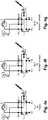
- the figure 3 illustrates a succession of configurations that the interface device can selectively adopt (by selectively, it is meant that the interface device can adopt at a given time only one configuration among the listed configurations).
- each of these drawers T1, T2 is movable by sliding vis-à-vis two bodies which correspond to it and between which it slides sealingly.
- the interface device comprises several drawers and several bodies P0, P1, P2 and possibly P3.
- the first drawer T1 slides with sealing between a base body P0 and an intermediate body P1.
- This basic body P0 carries said first port Pm1 and second port Pm2 as well as other ports of the interface device which will be presented below under the names of third port Pb1x, fourth port Pb2x, fifth port Pb3, sixth port Pb4 , port of start of restitution Pr1, port of restitution Pr2.
- the second drawer T2 slides sealingly between two bodies, one of which is a patient body P2 carrying the venous and arterial ports Px1, Px2 and the other body of which is either said intermediate body P1, or another intermediate body P3 (in the case where the device is distributed in at least two enclosures E, E2).
- This intermediate body P1 is crossed by conduits to allow the passage of fluid between internal circuits Pi in the first spool T1, and internal circuits in the second spool T2.
- the interface device 1 then comprises two enclosures E, E2.
- the first enclosure E contains the basic body P0, an intermediate body P1 and the first drawer T1 while the second enclosure E2 contains another intermediate body P3, the patient body P2 and the second drawer T2.
- the first drawer T1 is located in the first enclosure E where it is slidably mounted with sealing between the base body P0 and the first intermediate body P1, while the second drawer T2 is located in the second enclosure E2 where it is slidably mounted. sealing between the patient body P2 and the second intermediate body P3, the first and second intermediate bodies P1, P3 here being fluidly connected to each other by flexible pipes Cx. It is possible to ensure that each flexible pipe Cx has one end connected, optionally in a removable manner, to the first intermediate body P1 and a second end connected, optionally in a removable manner, to the second intermediate body P3.
- the drawers T1, T2 and the bodies P0, P1, P2, P3 are shaped so that depending on the respective positions of the drawers T1, T2 relative to the bodies, there are authorizations and / or prohibitions for the passage of fluid between ports Pb1x, Pb2x, Pb3, Pb4, Pr1, Pr2, Px1, Px2 carried by the bodies P1, P2 according to configurations device data 1.
- each drawer T1, T2 has several cells, in this case cells A1, A2, A3, A4, A5, A6A, A6B, A7, A8 for the first drawer T1 and cells B1, B2 for the second drawer T2 .
- the number and the configurations of these cells can vary according to the configurations that one wishes to implement.
- Each given configuration of the device is thus defined by a given sliding position of the first drawer T1 and a given sliding position of the second drawer T2.
- the interface device is adapted to selectively adopt a first configuration A1B1 (step 1) and second configuration A4B2 (step 4).
- This first configuration is useful at least for isolating the machine 2 from the circulatory system of the patient.
- the first port Pm1 is connected to the venous port Px1 to allow the passage of blood from the first port Pm1 to the venous port Px1, the second port Pm2 and the arterial port Px2 are also linked to each other. to allow the passage of blood from the arterial port Px2 to the second port Pm2.
- the ports Pm1, Px1, Pm2 Px2 are open and the other ports of the device are closed.
- This second A4B2 configuration is useful for circulating the blood in a loop passing successively by the circulatory system 3, the arterial tube X2, the arterial port Px2, the second port Pm2, the input port M2, the hemodialysis machine 2 and its internal circuit, the output port M1, the second port Pm1, the venous port Px1, the venous tube X1 and finally the circulatory system 3.
- One of the advantages of the interface device 1 according to the invention is that it makes it possible to switch from one configuration to another without having to manually disconnect a port from the machine. It is thus possible to authorize or interrupt the passage of fluid between the tubes X1, X2 and the hemodialysis machine while limiting the risks of contamination of the patient.
- the interface device is arranged so that when it is in its first configuration A1B1, the first port Pm1 and the second port Pm2 are then put into communication, via an internal circuit A10 to the interface device 1.
- the interface device is designed so that when it is in its second configuration A4B2, communication between the first port Pm1 and the second port Pm2 via this internal circuit A10 is then prohibited.
- This first configuration thus makes it possible to isolate the hemodialysis machine from the circulatory system 3 of the patient while allowing the circulation of the liquid fluid through the hemodialysis machine.
- Gases in the hemodialysis machine circuit can be evacuated and replaced by liquid passing through the internal circuit A10 of the interface device. This operation of filling the hemodialysis machine 2, the interface device 1 and the circuits which extend between the hemodialysis machine 2 and the interface device 1 with liquid is carried out without having to disconnect the input ports. and output M1, M2.
- the device 1 also comprises a third port Pb1x and this interface device 2 is adapted to selectively adopt an unlocking configuration A3B2 distinct from said first and second configurations A1B1, A4B2.
- the third port Pb1x is connected to only one of said venous port Px1 or arterial port Px2 while the first port Pm1 and the second port Pm2 are respectively isolated from the venous port Px1 and from the arterial port Px2, these venous and arterial ports also being isolated from each other.
- ports isolated from each other isolated from each other, it is meant that these ports do not communicate fluidly with each other.
- This A3B2 unlocking configuration allows the aspiration of a locking fluid present in the venous tube X1 and / or the arterial tube X2 in order to be able to release these tube (s) and allow the passage of blood / circulation of liquid fluid.
- a locking fluid is a substance with an anticoagulant function and a buffer function to prevent the passage of blood into the tube which contains it.
- the locking fluid can have an antiseptic function.
- locking fluid is injected into each tube that is to remain in the patient until the next hemodialysis. This locking fluid helps prevent clogging tube and the need to replace it.
- the interface device 1 it is possible to inject or aspirate locking fluid towards the venous tube X1 and / or the arterial tube X2 while leaving these tube (s) connected to the interface device 1 Again, this reduces the need for manipulation of fittings and ports and the associated risks to the patient.
- the system according to the invention can also include a venous aspiration syringe B1x of locking fluid connected to the third port Pb1x.
- the third port Px1 is designed to be connected either to the venous port Px1, or to the arterial port Px2 or possibly to a delivery port Pr2 intended to inject a fluid to be returned to the patient (for example a physiological serum or liquid drug ).
- this same third port Px1 can be used with each venous port Px1 and arterial Px2 to carry out the insertion of a lock or its aspiration.
- this third port is designed to be connected to any role with a suction syringe or with a locking fluid injection syringe. The coupling of each syringe is here carried out manually by the hemodialysis practitioner.
- This solution is also advantageous since it makes it possible to carry out operations for locking the venous or arterial ports using this single third port Pb1x.
- the interface device 1 can also include a fourth port Pb2x, this interface device being furthermore arranged so that when it is in its unlocking configuration A3B2, the fourth port Pb2x is then connected to one of said venous ports Px1 or arterial port Px2 which is not connected to said third port Pb1x, this fourth port Pb2x being isolated from the other ports of device 1.
- the third and fourth ports Pb1x, Pb2x are isolated from each other to allow locking fluid to be drawn into the venous tube X1 via the third port Pb1x and locking fluid. into the arterial tube X2 via the fourth Pb2x port.
- This suction can be done using a first suction means connected to the third single port Pb1x and a second suction means connected to the single fourth port Pb2x.
- the system according to the invention can comprise an arterial suction syringe B2x of locking fluid connected to the fourth port Pb2x in order to be able to aspirate the locking fluid coming from the arterial tube X2.
- suction circuits / suction means which are distinct from one another, which limits the risk that an operation for sucking up locking fluid in the venous tube or the arterial tube does not interfere with an operation. locking fluid suction operation in the other of these tubes.
- the interface device 1 also comprises a fifth port Pb3, the interface device being adapted to selectively adopt a locking configuration.
- A7B2 step7) distinct from said first, second configurations and from said unlocking configuration A1B1, A4B2, A3B2.
- the fifth port Pb3 is connected to said venous port Px1 while the first port Pm1, the second port Pm2, the third port Pb1x, the venous port Px1 and the arterial port Px2 are isolated from each other.
- the fourth port Pb2x and the fifth port Pb3 are also isolated from each other.
- this fifth port Pb3 is connected to the venous port Px1 while being isolated from all the other ports of the device.
- This locking configuration allows the injection, via the fifth port Pb3, of a locking fluid into the venous tube X1 in order to be able to prevent the presence of blood in this venous tube X1.
- the system according to the invention may include a venous injection syringe B3 of locking fluid connected to the fifth port Pb3 in order to be able to inject locking fluid into the venous tube X1.
- the interface device 1 also comprises a sixth port Pb4, the interface device 1 also being suitable for, in its locking configuration A7B2, the sixth port Pb4 is connected to said arterial port Px2 while being isolated from all other ports on the device.
- the interface device thus makes it possible to carry out the operations of removing or placing the locking fluid in the venous tube.
- X1 and the arterial tube X2 while leaving the hemodialysis machine 2 and the venous and arterial tubes X1, X2 connected / linked to the relevant ports of the interface device.
- the system according to the invention may include an arterial injection syringe B4 of locking fluid connected to the sixth port Pb4 in order to be able to inject locking fluid towards the arterial tube X2.
- the interface device also comprises a reproduction port Pr2 and the interface device 1 is furthermore adapted to selectively adopt a venous delivery configuration A6aB2 distinct from other configurations which can be adopted by the device A1B1, A4B2, A3B2, A7B2.
- the delivery port Pr2 is connected to said second port Pm2 in order to be able to inject a delivery fluid to the hemodialysis machine 2, the first port Pm1 then being connected to said venous port Px1 and isolated from all the others ports of the interface device, and the arterial port Px2 being at least isolated from the venous port Px1, from the first port Pm1 and from the second port Pm2.
- the device makes it possible to pass a fluid to be returned (recovery fluid) to the only second port Pm2 of the hemodialysis machine while allowing this hemodialysis machine to inject fluid into the tube.
- venous X1 via the output port M1 put in communication with the first port Pm1 and the venous port Px1.
- the system according to the invention may include a reserve R2 of fluid to be returned (by example a reserve of physiological serum, a dialysate, a drug in liquid form) connected to the return port Pr2 in order to be able to inject the fluid to be returned to the interface device when the interface device is in its venous return configuration A6aB2 , Etp5.
- a reserve R2 of fluid to be returned by example a reserve of physiological serum, a dialysate, a drug in liquid form
- the hemodialysis machine 2 As the hemodialysis machine 2 forms a circuit extending between its input port M2 and its output port M1, the hemodialysis machine pumps the restitution fluid from its input port M2 to its output port M1 thus push the blood contained in the machine and return it to the venous tube X1 then to the patient's circulatory system 3.
- the volume of blood contained in the hemodialysis machine 2, in the venous tube X1 and in the pipes connecting the hemodialysis machine 2 to the interface device 1 can be returned to the patient. This is particularly important to limit the amount of blood lost by the patient during hemodialysis.
- the device 1 is also adapted to selectively adopt an arterial delivery configuration A6bB2, Etp6B distinct from the other configurations that the interface device A1B1, A4B2, A3B2, A7B2, Etp1, Etp4, Etp5 can adopt. .
- the delivery port Pr2 can be connected to said arterial port Px2 in order to be able to inject a delivery fluid towards the arterial tube X2, the other ports of the device then being isolated from each other.
- the interface device can be adapted so that in its Etp6B arterial delivery configuration (see figure 4g ), the return port Pr2 is connected to the second port Pm2 of the hemodialysis machine while the first port Pm1 of the machine is connected to said arterial port Px2.
- the two venous and arterial ports are connected to the restitution port Pr2 or possibly to the first port Pm1 in order to simultaneously carry out the restitution.
- This solution saves time during restitution but it has the drawback of not controlling the volume of fluid returned to each tube X1, X2.
- this restitution fluid can be physiological serum.
- the device makes it possible to pass a fluid to be returned from the delivery port Pr2 to the arterial port Px2 while isolating the other ports from each other, the arterial tube X2 can thus be filled with fluid to return and the blood in this tube is pushed into the circulatory system 3.
- the device interface can be adapted so that when it is in its first configuration Etp1, its reproduction port Pr2 is then connected to at least one of said first port Pm1 and second port Pm2.
- the first and second ports Pm1, Pm2 can be degassed by injecting a fluid (liquid) via the return port Pr2.
- the interface device 1 also comprises a control mechanism arranged to be moved in a first direction S1 relative to the enclosure E of the interface device 1. This movement makes it possible to control a change in configuration of the device. interface and for example its passage from its first configuration A1B1 to its second configuration, second configuration A4B2.
- control mechanism makes it possible to control the passage from a current configuration in which the device is located to another configuration of the selected device, this other configuration being selected from among the different configurations that the device can selectively adopt.
- the operating mechanism only moves in the S1 direction so that the device can only pass once in a given configuration.
- the interface device comprises a physiological liquid supply port ⁇ e (a physiological liquid is for example physiological serum, dialysate or pure water) to an internal zone Zi of the interface device and a port evacuation of physiological liquid ( ⁇ s) out of this internal zone of the interface device (1).
- a physiological liquid is for example physiological serum, dialysate or pure water
- the interface device has a plurality portions of internal circuits Pi to the interface device and each of these portions of internal circuits being arranged to be selectively either connected between the physiological liquid supply port ⁇ e and the physiological liquid discharge port ⁇ s, or connected to at least one of said venous or arterial ports Px1, Px2.
- Each of the portions of internal circuits Pi can thus be filled with physiological liquid before being connected with one of the venous ports Px1 or arterial ports Px2.
- the supply port ⁇ e can be connected with a first physiological liquid reservoir optionally equipped with a debuller and the evacuation port ⁇ s can be connected with a second physiological liquid recovery reservoir.
- first and second reservoirs are preferably external to the interface device.
- the supply ports ⁇ e and discharge ⁇ s can be connected to one another via a circulation loop external to the interface device, this loop comprising a circulation pump, a bubbler and a physiological liquid reservoir.
- the objective is to supply the interface device with physiological liquid which does not contain bubbles.
- the portions of internal circuits Pi intended to be connected to one of the venous or arterial ports are formed in cells / sections A2, A3, A4, A5, A6a, A6b, A7 of a drawer T1. After filling a portion of the internal circuit Pi with physiological liquid, this portion is moved by the control mechanism towards the body Cp which blocks it until it arrives in a predetermined position with respect to the ports of the device which 'it must put in fluid communication.
- each of the cells A1 to A8 and B1, B2 of the drawers T1, T2 have several references each made up of a letter of a number followed by the character “'”. Each of these references in the cell corresponds to the port identified by a "P” and followed by the same letter and the same number.
- references B3 ', B1x', R1 ', R2', B4 'and B2x' are each opposite "X" which implies that when this cell A1 is in its position of use, then all the corresponding ports Pb3, Pb1x, Pr1, Pr2, Pb4 and Pb2x are blocked.
- the ports connected by this internal circuit are those designated by the references located along this line.
- a first step in using system 0 consists in mechanically connecting the ports of the interface device 1 to the hemodialysis machine 2, to the tubes X1, X2 and to at least some of the different devices B1x, B2x, B3, B4, R1 , R2 to use and place the device 1 in its first configuration (step 1).
- the device R1 can be a specific port of the hemodialysis machine 2 used only during the return of blood at the end of hemodialysis or possibly a blood or drug bag to be injected at the end of hemodialysis.
- step 1 the hemodialysis machine 2 is actuated to circulate liquid between the ports Pm1 and Pm2.
- the liquid then circulates in a loop between the machine 2 and the interface device 1, passing through the deaerator D which allows the bubbles of the liquid to be evacuated.
- the machine 2 carries out this circulation until it detects, or an operator detects, that the circuit of the machine and the interface device contains only liquid.
- first and second drawers T1, T2 are very distant from one another
- means can be provided for filling the circuit connecting these drawers with liquid.
- the first and second drawers have respective cells A2 and B1 which, when they are in the position of use, allow fluid to circulate between the ports Pm1 and Pm2 via a circuit passing through these cells A2, B1 (see the example of figure 2c and step 2 of the figure 3 / A2B1 configuration).
- the control mechanism for example a motor or an electromagnet
- the interface device After filling the interface device 1 and the internal circuit of the hemodialysis machine 2 with liquid, the control mechanism (for example a motor or an electromagnet) is actuated to cause the interface device to pass into its unlocking configuration A3B2 (step 3) which allows actuation of the venous and arterial suction syringes B1x and B2x.
- the locking fluid contained in the tubes X1, X2 is then sucked.
- the actuation of the syringes can be motorized and controlled by the control unit of the hemodialysis machine.
- the control mechanism is ordered so that the interface device passes into its second configuration A4B2 (step 4).
- the arterial tube X2 is placed in communication with the input port M2 and the venous tube X1 is placed in communication with the output port M1.
- the patient's blood can then circulate in a loop through the hemodialysis machine 2 for dialysis.
- this liquid can be brought via a return start port PR1 which belongs to the interface device.
- This Pr1 port can be connected to a specific blood outlet R1 of the hemodialysis machine or to a blood or drug bag R1.
- the control mechanism is actuated so that the interface device switches to the start of playback configuration A5B2 (step 5).
- the PR1 port is put in communication with the Pm2 port and the venous tube X1 is put in communication with the output port M1.
- the particular liquid to be returned then passes successively via the port Pr1, the port Pm2, the input port M2, the hemodialysis machine, the output port M1, the port Pm1 and finally it arrives at the venous tube X1.
- this step can be optional and that the system according to the invention may not include a device R1, a port PR1, and never go through the A5B2 configuration. In this case cell A4 could be deleted from drawer T1.
- This peripheral device R2 can be a reserve R2 of fluid to be returned when the interface device is in its configuration for venous recovery A6aB2.
- the fluid in reserve R2 is physiological saline used to push the blood remaining in the machine to the venous tube X1.
- the detection device 21 can detect the arrival of physiological serum and thus detect the end of the venous return operation.
- step 6A the control mechanism is actuated so that the interface device 1 switches to the arterial delivery configuration A6BB2 (step 6B) which authorizes the closing of the venous port Px1 and of the first port Pm1 and the setting in relation of the peripheral apparatus R2 with the arterial tube X2 via the return port Pr2 and the arterial port Px2.
- the restitution fluid contained in the reserve R2 can then circulate through the interface device 1 to expel the blood contained in the arterial tube X2 towards the patient.
- the return operation is completed when a predetermined volume of liquid has been returned to the arterial tube X2.
- step 6B the control mechanism is actuated so that the interface device 1 goes into the locking configuration A7B2 (step 7) which, on the one hand, allows the device B3 to be placed in communication with the venous tube.
- X1 via the Pb3 port and the Px1 port and on the other hand authorizes the communication of the device B4 with the arterial tube X2 via the Pb4 port and the Px2 port.
- the B3 device is a B3 venous injection syringe of locking fluid dedicated to injection to the X1 port and the B4 device is a B4 arterial injection syringe of locking fluid dedicated to injection to the port. X2.
- the device then being in emptying configuration A8B1.
- A8B1 the ports Px1 and Px2 are isolated and the ports Pm1 and Pm2 put into communication so that the fluid contained between the interface device 1 and the machine 2 can be withdrawn.
- the device 1 comprises an osteointegrated pillar having a connector implanted on the patient where each of the tubes X1 and X2 end.
- the venous port Px1 of the interface device 2 is connected to the venous tube X1 via an intermediate venous tube X1a, a first end of which is connected to the venous port Px1 and a second end of which terminates in a second removable connector of the patient.
- the arterial port Px2 of the interface device 2 is connected to the arterial tube X2 via an intermediate arterial tube X2a, a first end of which is connected to the arterial port Px2 and a second end of which terminates in the second removable connector of the patient.
- the connector implanted on the patient and the second removable connector of the patient are arranged to be able to be assembled with each other in a reversible manner and so that when they are assembled with each other then the venous tube X1 is tightly connected with the intermediate venous tube X1a and the arterial tube X2 is tightly connected with the intermediate arterial tube X2a.
- the patient-implanted connector has valves arranged to allow passage of fluid between the implanted tubes X1, X2 and intermediate tubes X1a, X2a when the implanted connector is assembled with a second removable connector and a valve control movable between a configuration.
- valve closure and a valve open configuration is in its valve open configuration.
- valve control can be moved between its closing configuration of the valves and its valve opening configuration as long as the implanted connector is assembled with the second removable connector.
- the valve control is preferably provided so that in the event of disassembly of the second removable connector with respect to the implanted connector, the valve control automatically moves from its valve opening configuration to its valve closing configuration. This prevents the implanted tubes X1, X2 from opening directly to the outside of the patient.
- This interface device 1 is also compatible with different types of hemodialysis machine 2 without requiring them to be modified.
Description
L'invention concerne le domaine de l'hémodialyse et en particulier un dispositif d'interface entre une machine à hémodialyse et des tubes destinés à être reliés au système circulatoire d'un patient.The invention relates to the field of hemodialysis and in particular to an interface device between a hemodialysis machine and tubes intended to be connected to the circulatory system of a patient.
L'hémodialyse consiste en la circulation du sang d'un patient vers une machine à hémodialyse, puis après avoir traité le sang à l'aide de la machine à hémodialyse, le sang est restitué vers système circulatoire du patient.Hemodialysis is the circulation of blood from a patient to a hemodialysis machine, then after processing the blood using the hemodialysis machine, the blood is returned to the patient's circulatory system.
La liaison entre la machine à hémodialyse et le patient se fait via au moins un tube et via un dispositif d'interface qui sert de connecteur amovible entre la machine à hémodialyse et le tube. Ce tube présente une extrémité qui débouche au niveau du système circulatoire.The connection between the hemodialysis machine and the patient is made via at least one tube and via an interface device which serves as a removable connector between the hemodialysis machine and the tube. This tube has one end which opens out at the level of the circulatory system.
Pour mettre en œuvre cette liaison, le personnel médical relie un premier conduit à la machine à hémodialyse et fait circuler un liquide dans ce premier conduit pour en chasser les gaz.To implement this connection, the medical staff connects a first duct to the hemodialysis machine and circulates a liquid in this first duct to expel the gases therefrom.
En parallèle, le personnel médical implante manuellement un cathéter doté dudit tube pour le relier au système circulatoire du patient puis il aspire du sang du patient via ce tube pour le remplir de sang et en évacuer les gaz.In parallel, the medical personnel manually implants a catheter provided with said tube to connect it to the circulatory system of the patient and then draws blood from the patient via this tube to fill it with blood and evacuate the gases therefrom.
Une fois le conduit et le cathéter purgés de leurs gaz, le conduit et le cathéter sont alors reliés mécaniquement entre eux via un dispositif d'interface. L'aspiration de sang vers la machine à hémodialyse peut alors commencer.Once the conduit and the catheter have been purged of their gases, the conduit and the catheter are then mechanically connected to each other via an interface device. Aspiration of blood to the hemodialysis machine can then begin.
En fin de séance d'hémodialyse, le cathéter relié au patient est débranché et du sérum physiologique y est injecté pour restituer le sang se trouvant dans ce cathéter vers le système circulatoire du patient.At the end of the hemodialysis session, the catheter connected to the patient is disconnected and physiological serum is injected therein to return the blood in this catheter to the patient's circulatory system.
Toutes ces opérations sont reproduites à chaque fois que l'on veut relier le patient à la machine à hémodialyse via un cathéter. Ainsi, dans les cas où l'on implante un cathéter veineux pour admettre du sang vers le patient et un cathéter artériel pour prélever du sang du patient, on doit multiplier les opérations manuelles. Le risque de contamination du système circulatoire du patient s'en trouve augmenté.All these operations are repeated each time you want to connect the patient to the hemodialysis machine. via a catheter. Thus, in cases where a venous catheter is implanted to admit blood to the patient and an arterial catheter to draw blood from the patient, manual operations must be increased. This increases the risk of contamination of the patient's circulatory system.
Un dispositif d'interface pour réaliser une hémodialyse est présenté sur le document brevet
Il serait par conséquent utile de développer un dispositif d'interface minimisant le risque de contamination du système circulatoire du patient.It would therefore be useful to develop an interface device which minimizes the risk of contamination of the patient's circulatory system.
Un objet de la présente invention est de fournir un dispositif d'interface entre une machine à hémodialyse et au moins un tube résolvant tout ou partie des inconvénients précités de l'art antérieur.An object of the present invention is to provide an interface device between a hemodialysis machine and at least one tube solving all or part of the aforementioned drawbacks of the prior art.
A cette fin il est proposé selon l'invention un dispositif d'interface entre une machine à hémodialyse et au moins un tube veineux destiné à être relié au système circulatoire d'un patient pour transférer du sang de la machine à hémodialyse vers le système circulatoire comportant les caractéristiques techniques de la revendication indépendante 1. Ce dispositif d'interface comprend
- un premier port adapté à être relié à un port de sortie de la machine à hémodialyse;
- un port veineux pour injecter du sang vers le tube veineux ;
- a first port adapted to be connected to an output port of the hemodialysis machine;
- a venous port to inject blood into the venous tube;
Le dispositif d'interface selon l'invention est également adapté à former une interface entre la machine à hémodialyse et un tube artériel destiné à être relié audit système circulatoire du patient pour transférer du sang du système circulatoire vers la machine à hémodialyse, ce dispositif d'interface comprenant également :
- un deuxième port adapté à être relié à un port d'entrée de la machine à hémodialyse ;
- un port artériel pour recevoir du sang du patient provenant du tube artériel, le dispositif d'interface étant en outre adapté pour interdire le passage de sang entre le deuxième port et le port artériel lorsque le dispositif se trouve dans sa première configuration et pour autoriser le passage de sang entre le deuxième port et le port artériel lorsque le dispositif se trouve dans sa deuxième configuration.
- a second port adapted to be connected to an input port of the hemodialysis machine;
- an arterial port for receiving the patient's blood from the arterial tube, the interface device being further adapted to prevent the passage of blood between the second port and the arterial port when the device is in its first configuration and to allow the passage of blood between the second port and the arterial port when the device is in its second configuration.
Le dispositif d'interface selon l'invention comporte également un troisième port, le dispositif d'interface étant adapté pour sélectivement adopter une configuration de déverrouillage distincte desdites première et deuxième configurations, dans cette configuration de déverrouillage le troisième port étant relié à un seul desdits port veineux ou port artériel alors que le premier port et le deuxième port sont respectivement isolés vis-à-vis du port veineux et du port artériel, ces ports veineux et artériel étant également isolés l'un de l'autre.The interface device according to the invention also comprises a third port, the interface device being adapted to selectively adopt an unlocking configuration distinct from said first and second configurations, in this unlocking configuration the third port being linked to only one of said. venous port or arterial port while the first port and the second port are respectively isolated vis-à-vis the venous port and the arterial port, these venous and arterial ports also being isolated from one another.
Le dispositif d'interface permet de relier des tubes veineux et artériel à une même machine à hémodialyse tout en permettant à l'aide de ce seul dispositif d'interface de :
- soit simultanément interdire le passage de fluide entre la machine à hémodialyse et le tube veineux et entre la machine à hémodialyse et le tube artériel en plaçant le dispositif d'interface dans sa première configuration ;
- soit simultanément autoriser le passage de fluide entre la machine à hémodialyse et le tube veineux et entre la machine à hémodialyse et le tube artériel en plaçant le dispositif d'interface dans sa deuxième configuration.
- either simultaneously prohibit the passage of fluid between the hemodialysis machine and the venous tube and between the hemodialysis machine and the arterial tube by placing the interface device in its first configuration;
- either simultaneously allow the passage of fluid between the hemodialysis machine and the venous tube and between the hemodialysis machine and the arterial tube by placing the interface device in its second configuration.
On peut ainsi, avec un même dispositif d'interface, sélectivement autoriser ou interdire une liaison fluidique veineuse et une liaison fluidique artérielle.It is thus possible, with the same interface device, to selectively authorize or prohibit a venous fluidic connection and an arterial fluidic connection.
Ceci facilite grandement les manipulations pour le personnel médical tout en réduisant le risque d'erreurs de manipulation.This greatly facilitates handling for medical personnel while reducing the risk of handling errors.
Pour la compréhension de la présente invention, sauf indication contraire tout port du dispositif d'interface qui n'est pas explicitement mentionné comme relié à un autre port du dispositif d'interface doit être considéré comme isolé vis-à-vis de tous les autres ports du dispositif d'interface.For the understanding of the present invention, unless otherwise indicated any port of the interface device which is not explicitly mentioned as connected to another port of the interface device should be considered as isolated from all others. interface device ports.
Par ailleurs, lorsque l'on indique que des ports donnés sont reliés entre eux, cela signifie qu'il y a une communication fluidique entre ces ports donnés.Furthermore, when it is indicated that given ports are linked together, it means that there is fluid communication between these given ports.
De même, lorsque l'on indique que deux ports donnés sont isolés l'un de l'autre, cela signifie qu'il n'existe pas de communication fluidique entre ces ports donnés.Likewise, when it is indicated that two given ports are isolated from each other, it means that there is no fluid communication between these given ports.
Le fluide transitant via le dispositif d'interface est un liquide. Par exemple, ce fluide est du sang, un dialysat, du sérum physiologique, un médicament sous forme liquide.The fluid passing through the interface device is a liquid. For example, this fluid is blood, dialysate, physiological saline, a drug in liquid form.
Selon un autre aspect, l'invention concerne un système d'hémodialyse comprenant une machine à hémodialyse et un dispositif d'interface selon l'un quelconque des modes de réalisations du dispositif d'interface décrit ci-après.According to another aspect, the invention relates to a hemodialysis system comprising a hemodialysis machine and an interface device according to any one of the embodiments of the interface device described below.
Dans ce système d'hémodialyse, le premier port Pm1 du dispositif d'interface est relié de manière amovible au port de sortie de la machine à hémodialyse et le deuxième port du dispositif d'interface est relié de manière amovible au port d'entrée de la machine à hémodialyse. La machine à hémodialyse comporte une pompe agencée pour faire circuler des fluides de son port d'entrée vers son port de sortie et le système d'hémodialyse comprend également un tube veineux et un tube artériel. Le tube veineux est relié au port veineux du dispositif d'interface. Ce tube veineux est destiné à être relié au système circulatoire d'un patient pour transférer, via le dispositif d'interface, du sang de la machine à hémodialyse vers le système circulatoire. Le tube artériel est relié au port artériel du dispositif d'interface. Ce tube artériel est destiné à être relié audit système circulatoire du patient pour transférer, via le dispositif d'interface, du sang du système circulatoire vers la machine à hémodialyse.In this hemodialysis system, the first port Pm1 of the interface device is removably connected to the output port of the hemodialysis machine and the second port of the interface device is removably connected to the input port of the hemodialysis machine. the hemodialysis machine. The hemodialysis machine has a pump arranged to circulate fluids from its inlet port to its outlet port and the hemodialysis system also includes a venous tube and an arterial tube. The venous tube is connected to the venous port of the interface device. This venous tube is intended to be connected to the circulatory system a patient to transfer blood from the hemodialysis machine to the circulatory system via the interface device. The arterial tube is connected to the arterial port of the interface device. This arterial tube is intended to be connected to said patient's circulatory system in order to transfer, via the interface device, blood from the circulatory system to the hemodialysis machine.
Le système d'hémodialyse selon l'invention est avantageux au moins pour les raisons énoncées ci-avant en référence au dispositif d'interface selon l'invention.The hemodialysis system according to the invention is advantageous at least for the reasons stated above with reference to the interface device according to the invention.
D'autres caractéristiques et avantages de l'invention ressortiront clairement de la description qui en est faite ci-après, à titre indicatif et nullement limitatif, en référence aux dessins annexés, dans lesquels:
- La figure la présente un système d'hémodialyse 0 selon l'invention comprenant une machine à
hémodialyse 2, un dispositif d'interface 1 selon l'invention et des tubes veineux et artériel X1, X2, ce dispositif d'interface 1 est ici contenu dans une seule enceinte E et est attaché aux tubes veineux et artériel X1, X2 et aux ports d'entrée et de sortie M1, M2 de la machine pour sélectivement autoriser ou interdire des liaisons fluidiques entre le port de la machine M1 et le tube X1 et entre le port M2 et le tube X2 ; - La
figure 1b illustre un système identique à celui de la figue 1a, la seule différence résidant dans le fait que le dispositif d'interface 1 est ici réparti dans deux enceintes E et E2 assemblées mécaniquement entre elles, de manière détachable, ce mode de réalisation permet d'avoir un dispositif d'interface monobloc et rigide lorsque les enceintes sont assemblées entre elles tout en permettant d'interrompre la liaison mécanique entre les tubes X1, X2 et les ports M1, M2 de la machine à hémodialyse en séparant le dispositif d'interface en deux parties respectivement contenues dans les enceintes distinctes E et E2 ;
- La
figure 1c illustre un système identique à celui de la figue 1b, la seule différence résidant dans le fait que le dispositif d'interface 1 est ici réparti dans deux enceintes E et E2 qui sont reliées entre elles par un tube veineux intermédiaire X1a et un tube artériel intermédiaire X2a qui sont déformables, les enceintes E, E2 étant ici éloignée l'une de l'autre, ce mode de réalisation permet d'avoir un dispositif d'interface en deux blocs rigides et séparés l'un de l'autre par des tubes souples X1a, X2a dont la longueur peut varier en fonction du besoin, ce mode permet d'interrompre la liaison mécanique entre les tubes X1, X2 et les ports M1, M2 de la machine à hémodialyse en détachant les tubes intermédiaires vis-à-vis de l'une des enceintes E ou E2, les liaisons fluidiques respectives entre les ports M1, M2 et les tubes veineux et artériel X1, X2 pouvant être interrompues soit en actionnant un premier tiroir du dispositif d'interface placé dans la première enceinte E soit en actionnant un second tiroir du dispositif d'interface placé dans la deuxième enceinte E2, on a donc une fonction d'interruption de liaison fluidique qui est redondante et répartie dans des enceintes séparées ; - La
figure 1d illustre un système identique à celui de la figue 1c, la seule différence résidant dans le fait que la seconde enceinte E2 est intégrée dans un tissu du patient, elle peut par exemple être implantée en sous cutané ou être implantée de manière transcutanée comme sur cettefigure 1d , cette seconde enceinte E2 peut éventuellement présenter une surface externe ostéo intégrée ; - La
figure 2a présente un mode de réalisation dusystème 0 avec un dispositif d'interface 1 selon l'invention intégré dans une seule enceinte comme sur la figure la ;
- La
figure 2b présente un mode de réalisation du système 0 avecun dispositif d'interface 1 selon l'invention réparti dans deux enceintes E, E2 distinctes et assemblées mécaniquement l'une contre l'autre de manière détachable comme sur lafigure 1b ; - La
figure 2c présente un mode de réalisation du système 0 avecun dispositif d'interface 1 selon l'invention réparti dans deux enceintes E, E2 distinctes reliées entre elles via des tubes intermédiaires souples X1a, X2a comme sur lafigure 1c ; - la
figure 3 décrit une succession d'étapes avec de configurations prises par le dispositif d'interface selon l'invention - les
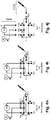
figures 4a ,4b, 4c, 4d ,4e, 4f, 4g ,4h, 4i, 4j illustrent respectivement les différentes étapes de fonctionnement Etp0, Etp1, Etp2, Etp3a, Etp3b, Etp4, Etp5, Etp6B, Etp7A, Etp7b, Etp8 d'un dispositif d'interface 1 selon l'invention (ce dispositif d'interface 1 desfigures 4a à 4j est plus facile à fabriquer car il présente un nombre réduit de ports et de positions / configurations par rapport à celui desfigures 2a à 2c ).
- Figure la shows a
hemodialysis system 0 according to the invention comprising ahemodialysis machine 2, aninterface device 1 according to the invention and venous and arterial tubes X1, X2, thisinterface device 1 is contained here in a single enclosure E and is attached to the venous and arterial tubes X1, X2 and to the inlet and outlet ports M1, M2 of the machine to selectively allow or prohibit fluid connections between the port of the machine M1 and the tube X1 and between port M2 and tube X2; - The
figure 1b illustrates a system identical to that of fig 1a, the only difference residing in the fact that theinterface device 1 is here distributed in two enclosures E and E2 mechanically assembled together, in a detachable manner, this embodiment makes it possible to have a one-piece and rigid interface device when the enclosures are assembled together while allowing the mechanical connection between the tubes X1, X2 and the ports M1, M2 of the hemodialysis machine to be interrupted by separating the interface device into two parts respectively contained in the separate enclosures E and E2;
- The
figure 1c illustrates a system identical to that of fig 1b, the only difference residing in the fact that theinterface device 1 is here distributed in two enclosures E and E2 which are connected to each other by an intermediate venous tube X1a and an intermediate arterial tube X2a which are deformable, the enclosures E, E2 being here remote from one another, this embodiment makes it possible to have an interface device in two rigid blocks and separated from each other by tubes flexible X1a, X2a, the length of which can vary according to need, this mode makes it possible to interrupt the mechanical connection between the tubes X1, X2 and the ports M1, M2 of the hemodialysis machine by detaching the intermediate tubes vis-à-vis of one of the enclosures E or E2, the respective fluidic links between the ports M1, M2 and the venous and arterial tubes X1, X2 being able to be interrupted either by actuating a first drawer of the interface device placed in the first enclosure E or by operating a sec ond drawer of the interface device placed in the second enclosure E2, there is therefore a fluidic link interruption function which is redundant and distributed in separate enclosures; - The
figure 1d illustrates a system identical to that of fig 1c, the only difference residing in the fact that the second enclosure E2 is integrated into a tissue of the patient, it can for example be implanted subcutaneously or be implanted transcutaneously as on thisfigure 1d , this second enclosure E2 may optionally have an integrated osteo external surface; - The
figure 2a presents an embodiment of thesystem 0 with aninterface device 1 according to the invention integrated into a single enclosure as in FIG. 1a;
- The
figure 2b presents an embodiment of thesystem 0 with aninterface device 1 according to the invention distributed in two separate enclosures E, E2 and assembled mechanically one against the other in a detachable manner as on thefigure 1b ; - The
figure 2c presents an embodiment of thesystem 0 with aninterface device 1 according to the invention distributed in two separate enclosures E, E2 interconnected via flexible intermediate tubes X1a, X2a as on thefigure 1c ; - the
figure 3 describes a succession of steps with configurations taken by the interface device according to the invention - the
figures 4a ,4b, 4c, 4d ,4th, 4f, 4g ,4h, 4i, 4d respectively illustrate the different operating steps Etp0, Etp1, Etp2, Etp3a, Etp3b, Etp4, Etp5, Etp6B, Etp7A, Etp7b, Etp8 of aninterface device 1 according to the invention (thisinterface device 1 offigures 4a to 4j is easier to manufacture because it has a reduced number of ports and positions / configurations compared to that offigures 2a to 2c ).
Selon un aspect général, l'invention porte sur un système d'hémodialyse 0 illustré au travers des figures la à 2c et au travers des
Chacun des tubes X1, X2 est préférentiellement formé dans un conduit souple, par exemple thermoplastique compatible avec un usage médical (polyuréthane, PEEK, silicone ou autre), pour faciliter sa manipulation et son cheminement entre le système circulatoire 3 et le dispositif d'interface 1.Each of the tubes X1, X2 is preferably formed in a flexible conduit, for example thermoplastic compatible with medical use (polyurethane, PEEK, silicone or other), to facilitate its handling and its path between the
Le tube veineux X1 est essentiellement destiné à l'injection de fluide de la machine 2 vers le patient, et le tube artériel X2 est essentiellement destiné au prélèvement (aspiration) de fluide du patient vers la machine à hémodialyse 2.The venous tube X1 is primarily intended for the injection of fluid from the
La mise en relation des tubes avec le système circulatoire 3 se fait soit via une fistule artérioveineuse, via un cathéter central tunnélisé dans le patient (un cathéter central tunnelisé est un cathéter restant en place dans le corps du patient entre deux hémodialyses) ou via une implantation d'un cathéter d'hémodialyse non tunnélisé (ces tubes pouvant appartenir à un ou plusieurs cathéters). Plus précisément, le dispositif d'interface 1 selon l'invention forme :
- une interface entre la machine à hémodialyse 2 et un tube artériel X2 destiné à être relié
audit système circulatoire 3 du patient pour transférer du sang du système circulatoire 3 vers la machine à hémodialyse 2 ; et - une interface entre la machine à hémodialyse 2 et au moins un tube veineux X1 pour transférer du sang de la machine à hémodialyse vers le système circulatoire 3.
- an interface between the
hemodialysis machine 2 and an arterial tube X2 intended to be connected to saidcirculatory system 3 of the patient for transferring blood from thecirculatory system 3 to thehemodialysis machine 2; and - an interface between the
hemodialysis machine 2 and at least one venous tube X1 to transfer blood from the hemodialysis machine to thecirculatory system 3.
Ce dispositif d'interface 1 comprend :
- un premier port Pm1 adapté à être relié, préférentiellement de manière amovible via un premier raccord, à un port de sortie M1 de la machine à hémodialyse 2 ; et
- un deuxième port Pm2 adapté à être relié, préférentiellement de manière amovible via un second raccord éventuellement solidarisé audit premier raccord, à un port d'entrée M2 de la machine à hémodialyse ;
- un port veineux Px1 pour injecter du sang vers le tube veineux X1, ce port veineux Px1 étant préférentiellement attaché de manière amovible, via un raccord, au tube veineux X1 ; et
- un port artériel Px2 pour recevoir (faire circuler, prélever par exemple par aspiration) du sang du patient provenant du tube artériel X2, ce port artériel Px2 est préférentiellement attaché de manière amovible, via un raccord, au tube artériel X2.
- a first port Pm1 adapted to be connected, preferably removably via a first connector, to an output port M1 of the
hemodialysis machine 2; and - a second port Pm2 adapted to be connected, preferably removably via a second connector optionally secured to said first connector, to an input port M2 of the hemodialysis machine;
- a Px1 venous port to inject blood into the venous tube X1, this venous port Px1 preferably being removably attached, via a connector, to the venous tube X1; and
- an arterial port Px2 to receive (circulate, take for example by suction) the patient's blood coming from the arterial tube X2, this arterial port Px2 is preferably removably attached, via a connector, to the arterial tube X2.
Le deuxième port Pm2 du dispositif d'interface 1 est adapté à transférer du sang du dispositif d'interface 1 vers un port d'entrée M2 de la machine à hémodialyse 2.The second port Pm2 of the
La machine à hémodialyse comporte une pompe M agencée pour pomper / faire circuler des fluides de son port d'entrée M2 vers son port de sortie M1.The hemodialysis machine comprises a pump M arranged to pump / circulate fluids from its input port M2 to its output port M1.
Le premier port Pm1 du dispositif d'interface 1 est adapté à recevoir du sang provenant du port de sortie M1 pour le transférer vers le tube veineux X1.The first port Pm1 of the
La machine à hémodialyse 2 est aussi adaptée à réaliser des échanges entre le fluide qu'elle transfert, en l'occurrence du sang du patient, et un dialysat liquide pour permettre une épuration du fluide (sang). Pour cela la machine à hémodialyse comporte un circuit interne relié d'un côté au port d'entrée M2 et d'un autre côté au port de sortie M1.The
La pompe M de la machine à hémodialyse est préférentiellement une pompe péristaltique, pour transférer du fluide du port d'entrée M2 vers le port de sortie M1 avec un débit précisément contrôlé.The pump M of the hemodialysis machine is preferably a peristaltic pump, to transfer fluid from the inlet port M2 to the outlet port M1 with a precisely controlled flow rate.
Ce circuit interne de la machine à hémodialyse comporte préférentiellement au moins une membrane semi-perméable 20 permettant de réaliser des échanges entre le fluide / le sang et le dialysat formulé chimiquement et/ou des filtres pour épurer le fluide / sang.This internal circuit of the hemodialysis machine preferably comprises at least one
Préférentiellement, cette membrane semi-perméable 20 permet des échanges entre un circuit où passe le sang du patient et un circuit de dialysat. Le circuit de dialysat s'étend depuis une réserve de dialysat G1 préalablement formulé vers une réserve de dialysat usagé G2 en passant par une zone de contact contre la membrane semi-perméable 20 pour réaliser les échanges avec le sang du patient.Preferably, this
Le débit et la qualité de ce dialysat peuvent être contrôlés à l'aide d'une pompe à dialysat et/ou de valves et/ou de capteurs d'analyse du dialysat et/ou de capteurs d'analyse de fonctionnement de la membrane semi-perméable 20 et/ou de capteurs de pression de dialysat et/ou de capteur de quantité de dialysat restant dans la réserve G1 et/ou de capteur de quantité de dialysat usagé présent dans la réserve G2.The flow rate and the quality of this dialysate can be controlled using a dialysate pump and / or valves and / or dialysate analysis sensors and / or semi-membrane function analysis sensors. -permeable 20 and / or dialysate pressure sensors and / or sensor for the amount of dialysate remaining in the reserve G1 and / or sensor for the amount of used dialysate present in the reserve G2.
La machine à hémodialyse 2 comporte aussi un débulleur D destiné à retirer des bulles de gaz contenues dans le fluide transféré via la machine à hémodialyse 2. Ici, le débulleur D est relié en série entre les ports d'entrée M2 et de sortie M1 et il se trouve préférentiellement entre le port M2 et la membrane. Si besoin, la machine peut comporter d'autres débulleurs pour s'assurer de ne pas diffuser de liquide contenant des bulles vers le patient.The
La machine à hémodialyse peut aussi comporter un dispositif de détection 21 pour détecter des bulles et/ou des impuretés et/ou un débit de fluide entre ses ports d'entrée M2 et de sortie M1 et/ou une pression du fluide transitant via la machine 2 et/ou un niveau de dialysat dans une réserve de dialysat reliée à la machine 2 pour amener ce dialysat au contact de la membrane semi-perméable.The hemodialysis machine can also include a
Ce dispositif de détection 21 est relié à une unité électronique de commande de la machine à hémodialyse 2 pour commander le fonctionnement de la pompe M en fonction de mesures réalisées par ce dispositif de détection 21.This
Cette unité électronique peut aussi être reliée à certains au moins desdits capteurs du circuit de dialysat et à des actionneurs du circuit de dialysat pour par exemple de commander des débits de dialysat dans le circuit de dialysat, des dosages de dialysat avec d'autres constituants.This electronic unit can also be connected to at least some of said sensors of the dialysate circuit and to actuators of the dialysate circuit for example to control the flow rates of dialysate in the dialysate circuit, dosages of dialysate with other constituents.
Cette unité électronique peut aussi être reliée à un ou plusieurs capteurs d'état de la membrane semi-perméable pour commander les paramètres de fonctionnement des différents actionneurs dont la pompe M en fonction de mesures réalisées à l'aide de ce/ces capteur(s) d'état.This electronic unit can also be connected to one or more state sensors of the semi-permeable membrane to control the operating parameters of the various actuators including the M pump as a function of measurements made using this / these sensor (s). ) state.
La machine à hémodialyse peut aussi comporter une interface de communication adaptée à détecter une configuration courante du dispositif d'interface 1 selon l'invention de manière à ajuster le fonctionnement de la machine à hémodialyse en fonction de la configuration courante du dispositif d'interface 1 ainsi détectée. Cette interface de communication peut comprendre une connectique reliant, de manière détachable, la machine à hémodialyse 1 au dispositif d'interface 1.The hemodialysis machine may also include a communication interface suitable for detecting a current configuration of the
Cette interface de communication peut être adaptée pour transmettre :
- du dispositif d'interface 1 vers la machine à hémodialyse 2 un signal de configuration courante du dispositif d'interface 1 représentatif d'une configuration courante adoptée par
ce dispositif d'interface 1 ; et/ou - de la machine à hémodialyse 2 vers le dispositif d'interface 1, un signal de changement de configuration, le dispositif d'interface 1 comportant un actionneur, par exemple un moteur, commandant le changement de configuration du dispositif d'interface 1 en fonction du signal de changement de configuration reçu par le dispositif d'interface 1 de manière à faire passer le dispositif d'interface d'une configuration courante vers une autre configuration choisie dans une succession de configurations prédéfinies. Les différentes configurations sélectivement adoptées par le dispositif d'interface seront présentées ci-après.
- from the
interface device 1 to thehemodialysis machine 2, a current configuration signal from theinterface device 1 representative of a current configuration adopted by thisinterface device 1; and or - from the
hemodialysis machine 2 to theinterface device 1, a configuration change signal, theinterface device 1 comprising an actuator, for example a motor, controlling the configuration change of theinterface device 1 as a function of the configuration change signal received by theinterface device 1 so as to switch the interface device from one current configuration to another configuration chosen from a succession of predefined configurations. The various configurations selectively adopted by the interface device will be presented below.
La
Pour illustrer ces différentes configurations, on a représenté deux tiroirs T1, T2, chacun de ces tiroirs T1, T2 est mobile par coulissement vis-à-vis deux corps qui lui correspondent et entre lesquels il coulisse à étanchéité. Ici, le dispositif d'interface comporte plusieurs tiroirs et plusieurs corps P0, P1, P2 et éventuellement P3.To illustrate these different configurations, two drawers T1, T2 have been shown, each of these drawers T1, T2 is movable by sliding vis-à-vis two bodies which correspond to it and between which it slides sealingly. Here, the interface device comprises several drawers and several bodies P0, P1, P2 and possibly P3.
Le premier tiroir T1 coulisse à étanchéité entre un corps de base P0 et un corps intermédiaire P1. Ce corps de base P0 porte lesdits premier port Pm1 et deuxième port Pm2 ainsi que d'autre ports du dispositif d'interface qui seront présentés ci-après sous les noms de troisième port Pb1x, quatrième port Pb2x, cinquième port Pb3, sixième port Pb4, port de début de restitution Pr1, port de restitution Pr2.The first drawer T1 slides with sealing between a base body P0 and an intermediate body P1. This basic body P0 carries said first port Pm1 and second port Pm2 as well as other ports of the interface device which will be presented below under the names of third port Pb1x, fourth port Pb2x, fifth port Pb3, sixth port Pb4 , port of start of restitution Pr1, port of restitution Pr2.
Le second tiroir T2 coulisse à étanchéité entre deux corps dont un est un corps patient P2 portant les ports veineux et artériel Px1, Px2 et dont l'autre corps est soit ledit corps intermédiaire P1, soit autre corps intermédiaire P3 (dans le cas où le dispositif est réparti dans au moins deux enceintes E, E2).The second drawer T2 slides sealingly between two bodies, one of which is a patient body P2 carrying the venous and arterial ports Px1, Px2 and the other body of which is either said intermediate body P1, or another intermediate body P3 (in the case where the device is distributed in at least two enclosures E, E2).
Dans les applications où le dispositif d'interface 1 est contenu dans une seule enceinte E, comme sur la
Ce corps intermédiaire P1 est traversé de conduits pour permettre le passage de fluide entre des circuits internes Pi au premier tiroir T1, et des circuits internes au second tiroir T2.This intermediate body P1 is crossed by conduits to allow the passage of fluid between internal circuits Pi in the first spool T1, and internal circuits in the second spool T2.
Dans d'autres modes de réalisations, comme celui de la
Le premier tiroir T1 se trouve dans la première enceinte E où il est monté coulissant à étanchéité entre le corps de base P0 et le premier corps intermédiaire P1, alors que le second tiroir T2 se trouve dans la deuxième enceinte E2 où il est monté coulissant à étanchéité entre le corps patient P2 et le second corps intermédiaire P3, les premier et second corps intermédiaires P1, P3 étant ici reliés fluidiquement entre eux par des conduites souples Cx. On peut faire en sorte que chaque conduite souple Cx ait une extrémité reliée, éventuellement de manière amovible, au premier corps intermédiaire P1 et une seconde extrémité reliée, éventuellement de manière amovible, au second corps intermédiaire P3.The first drawer T1 is located in the first enclosure E where it is slidably mounted with sealing between the base body P0 and the first intermediate body P1, while the second drawer T2 is located in the second enclosure E2 where it is slidably mounted. sealing between the patient body P2 and the second intermediate body P3, the first and second intermediate bodies P1, P3 here being fluidly connected to each other by flexible pipes Cx. It is possible to ensure that each flexible pipe Cx has one end connected, optionally in a removable manner, to the first intermediate body P1 and a second end connected, optionally in a removable manner, to the second intermediate body P3.
Dans chacun de ces modes des
Pour cela chaque tiroir T1, T2 comporte plusieurs cellules, en l'occurrence les cellules A1, A2, A3, A4, A5, A6A, A6B, A7, A8 pour le premier tiroir T1 et les cellules B1, B2 pour le second tiroir T2. Le nombre et les configurations de ces cellules peuvent varier en fonction des configurations que l'on souhaite mettre en œuvre.For this each drawer T1, T2 has several cells, in this case cells A1, A2, A3, A4, A5, A6A, A6B, A7, A8 for the first drawer T1 and cells B1, B2 for the second drawer T2 . The number and the configurations of these cells can vary according to the configurations that one wishes to implement.
Chaque configuration donnée du dispositif, est ainsi définie par une position donnée de coulissement du premier tiroir T1 et une position donnée de coulissement du second tiroir T2.Each given configuration of the device is thus defined by a given sliding position of the first drawer T1 and a given sliding position of the second drawer T2.
Comme on le comprend de la
Dans sa première configuration A1B1 :
- le passage de sang entre le premier port Pm1 et le port veineux Px1 est interdit ; et
- le passage de sang entre le deuxième port Pm2 et le port artériel Px2 est interdit.
- the passage of blood between the first port Pm1 and the venous port Px1 is prohibited; and
- the passage of blood between the second port Pm2 and the arterial port Px2 is prohibited.
Cette première configuration est utile au moins pour isoler la machine 2 vis-à-vis du système circulatoire du patient.This first configuration is useful at least for isolating the
Dans sa deuxième configuration A4B2 (étape 4), le premier port Pm1 est relié au port veineux Px1 pour permettre le passage de sang du premier port Pm1 vers le port veineux Px1, le deuxième port Pm2 et le port artériel Px2 sont aussi reliés entre eux pour permettre le passage de sang du port artériel Px2 vers le deuxième port Pm2. Dans cette deuxième configuration, seuls les ports Pm1, Px1, Pm2 Px2 sont ouverts et les autres ports du dispositif sont fermés.In its second A4B2 configuration (step 4), the first port Pm1 is connected to the venous port Px1 to allow the passage of blood from the first port Pm1 to the venous port Px1, the second port Pm2 and the arterial port Px2 are also linked to each other. to allow the passage of blood from the arterial port Px2 to the second port Pm2. In this second configuration, only the ports Pm1, Px1, Pm2 Px2 are open and the other ports of the device are closed.
Cette deuxième configuration A4B2 est utile pour faire circuler le sang en boucle en passant successivement par le système circulatoire 3, le tube artériel X2, le port artériel Px2, le deuxième port Pm2, le port d'entrée M2, la machine à hémodialyse 2 et son circuit interne, le port de sortie M1, le deuxième port Pm1, le port veineux Px1, le tube veineux X1 et finalement le système circulatoire 3.This second A4B2 configuration is useful for circulating the blood in a loop passing successively by the
Un des avantages du dispositif d'interface 1 selon l'invention est qu'il permet de passer d'une configuration à un autre sans avoir à débrancher manuellement un port de la machine. On peut ainsi autoriser ou interrompre le passage de fluide entre les tubes X1, X2 et la machine à hémodialyse tout en limitant les risques de contamination du patient.One of the advantages of the
Préférentiellement, le dispositif d'interface est agencé pour que lorsqu'il se trouve dans sa première configuration A1B1, le premier port Pm1 et le deuxième port Pm2 soient alors mis en communication, via un circuit interne A10 au dispositif d'interface 1.Preferably, the interface device is arranged so that when it is in its first configuration A1B1, the first port Pm1 and the second port Pm2 are then put into communication, via an internal circuit A10 to the
Préférentiellement, le dispositif d'interface est agencé pour que lorsqu'il se trouve dans sa deuxième configuration A4B2, la communication entre le premier port Pm1 et le deuxième port Pm2 via ce circuit interne A10 soit alors interdite.Preferably, the interface device is designed so that when it is in its second configuration A4B2, communication between the first port Pm1 and the second port Pm2 via this internal circuit A10 is then prohibited.
Ainsi, dans la première configuration, on peut mettre en communication les premier et second ports Pm1 et Pm2 du dispositif 1 via un circuit interne A10 ce qui permet de mettre en relation le port de sortie M1 et le port d'entrée M2 tout en isolant ces ports M1, M2 des tubes artériel et veineux X2, X1.Thus, in the first configuration, it is possible to put in communication the first and second ports Pm1 and Pm2 of the
Cette première configuration permet ainsi d'isoler la machine à hémodialyse vis-à-vis du système circulatoire 3 du patient tout en autorisant la circulation du fluide liquide au travers de la machine à hémodialyse. Des gaz se trouvant dans le circuit de la machine à hémodialyse peuvent être évacués et remplacés par du liquide transitant via le circuit interne A10 du dispositif d'interface. Cette opération de remplissage en liquide de la machine à hémodialyse 2, du dispositif d'interface 1 et des circuits qui s'étendent entre la machine à hémodialyse 2 et le dispositif d'interface 1 est réalisée sans avoir à débrancher les ports d'entrée et de sortie M1, M2.This first configuration thus makes it possible to isolate the hemodialysis machine from the
Comme illustré sur différentes figures la à 2c, le dispositif 1 comporte également un troisième port Pb1x et ce dispositif d'interface 2 est adapté à sélectivement adopter une configuration de déverrouillage A3B2 distincte desdites première et deuxième configurations A1B1, A4B2.As illustrated in various Figures 1a to 2c, the
Dans cette configuration de déverrouillage A3B2 Etp3a, le troisième port Pb1x est relié à un seul desdits port veineux Px1 ou port artériel Px2 alors que le premier port Pm1 et le deuxième port Pm2 sont respectivement isolés vis-à-vis du port veineux Px1 et du port artériel Px2, ces ports veineux et artériels étant également isolés l'un de l'autre. Par ports isolés les uns des autres, isolés l'un de l'autre, on entend que ces ports ne communiquent pas fluidiquement entre eux.In this A3B2 Etp3a unlocking configuration, the third port Pb1x is connected to only one of said venous port Px1 or arterial port Px2 while the first port Pm1 and the second port Pm2 are respectively isolated from the venous port Px1 and from the arterial port Px2, these venous and arterial ports also being isolated from each other. By ports isolated from each other, isolated from each other, it is meant that these ports do not communicate fluidly with each other.
Cette configuration de déverrouillage A3B2 permet l'aspiration d'un fluide de verrouillage présent dans le tube veineux X1 et/ou le tube artériel X2 pour pouvoir libérer ce(s) tube(s) et y autoriser le passage de sang / la circulation de fluide liquide. Un fluide de verrouillage est une substance ayant une fonction anticoagulante et une fonction de tampon pour éviter le passage de sang dans le tube qui le contient. Eventuellement, le fluide de verrouillage peut avoir une fonction antiseptique.This A3B2 unlocking configuration allows the aspiration of a locking fluid present in the venous tube X1 and / or the arterial tube X2 in order to be able to release these tube (s) and allow the passage of blood / circulation of liquid fluid. A locking fluid is a substance with an anticoagulant function and a buffer function to prevent the passage of blood into the tube which contains it. Optionally, the locking fluid can have an antiseptic function.
Typiquement, après avoir réalisé une hémodialyse, du fluide de verrouillage est injecté dans chaque tube devant rester dans le patient jusqu'à l'hémodialyse suivante. Ce fluide de verrouillage permet d'éviter un bouchage du tube et le besoin de le remplacer.Typically, after performing hemodialysis, locking fluid is injected into each tube that is to remain in the patient until the next hemodialysis. This locking fluid helps prevent clogging tube and the need to replace it.
Grâce au dispositif d'interface 1, on peut injecter ou aspirer du fluide de verrouillage vers le tube veineux X1 et/ou le tube artériel X2 tout en laissant ce(s) tube(s) connecté(s) au dispositif d'interface 1. Encore une fois, on réduit ainsi le besoin de manipulation des raccords et ports et les risques associés pour le patient.Thanks to the
Afin d'aspirer du fluide de verrouillage provenant du tube veineux X1, le système selon l'invention peut aussi comporter une seringue d'aspiration veineuse B1x de fluide de verrouillage reliée au troisième port Pb1x.In order to aspirate locking fluid from the venous tube X1, the system according to the invention can also include a venous aspiration syringe B1x of locking fluid connected to the third port Pb1x.
Dans le mode de réalisation présenté aux
Cette solution est aussi avantageuse puisqu'elle permet de réaliser des opérations de verrouillage des ports veineux ou artériel à l'aide de ce seul troisième port Pb1x.This solution is also advantageous since it makes it possible to carry out operations for locking the venous or arterial ports using this single third port Pb1x.
Pour réaliser un verrouillage veineux ou artériel, il suffit de disposer le dispositif d'interface en configuration de déverrouillage et d'injecter un verrou artériel ou veineux via celui des ports Px1 ou Px2 relié au troisième port Pb1x.To achieve venous or arterial locking, all you have to do is place the interface device in the unlocking configuration and inject an arterial or venous lock via that of the connected Px1 or Px2 ports. to the third port Pb1x.
Alternativement, comme illustré sur les
Préférentiellement, dans cette configuration de déverrouillage A3B2, les troisième et quatrième ports Pb1x, Pb2x sont isolés l'un de l'autre pour permettre d'aspirer du fluide de verrouillage dans le tube veineux X1 via le troisième port Pb1x et du fluide de verrouillage dans le tube artériel X2 via le quatrième port Pb2x. Cette aspiration peut se faire à l'aide d'un premier moyen d'aspiration relié au seul troisième port Pb1x et d'un second moyen d'aspiration relié au seul quatrième port Pb2x.Preferably, in this unlocking configuration A3B2, the third and fourth ports Pb1x, Pb2x are isolated from each other to allow locking fluid to be drawn into the venous tube X1 via the third port Pb1x and locking fluid. into the arterial tube X2 via the fourth Pb2x port. This suction can be done using a first suction means connected to the third single port Pb1x and a second suction means connected to the single fourth port Pb2x.
A cette fin, le système selon l'invention peut comporter une seringue d'aspiration artérielle B2x de fluide de verrouillage reliée au quatrième port Pb2x pour pouvoir aspirer du fluide de verrouillage provenant du tube artériel X2.To this end, the system according to the invention can comprise an arterial suction syringe B2x of locking fluid connected to the fourth port Pb2x in order to be able to aspirate the locking fluid coming from the arterial tube X2.
On a ainsi des circuits d'aspiration / moyens d'aspiration distincts l'un de l'autre ce qui limite le risque qu'une opération d'aspiration de fluide de verrouillage dans le tube veineux ou le tube artériel n'interfère avec une opération d'aspiration de fluide de verrouillage dans l'autre de ces tubes.There are thus suction circuits / suction means which are distinct from one another, which limits the risk that an operation for sucking up locking fluid in the venous tube or the arterial tube does not interfere with an operation. locking fluid suction operation in the other of these tubes.
Selon un mode de réalisation préférentiel, le dispositif d'interface 1 comporte également un cinquième port Pb3, le dispositif d'interface étant adapté pour sélectivement adopter une configuration de verrouillage A7B2 (étape7) distincte desdites première, deuxième configurations et de ladite configuration de déverrouillage A1B1, A4B2, A3B2. Dans cette configuration de verrouillage A7B2, le cinquième port Pb3 est relié audit port veineux Px1 alors que le premier port Pm1, le deuxième port Pm2, le troisième port Pb1x, le port veineux Px1 et le port artériel Px2 sont isolés les uns des autres.According to a preferred embodiment, the
Dans cette configuration de verrouillage A7B2, le quatrième port Pb2x et le cinquième port Pb3 sont également isolés l'un de l'autre.In this A7B2 locking configuration, the fourth port Pb2x and the fifth port Pb3 are also isolated from each other.
Dans cette configuration de verrouillage, ce cinquième port Pb3 est relié au port veineux Px1 tout en étant isolé de tous les autres ports du dispositif.In this locking configuration, this fifth port Pb3 is connected to the venous port Px1 while being isolated from all the other ports of the device.
Cette configuration de verrouillage permet l'injection, via le cinquième port Pb3, d'un fluide de verrouillage jusque dans le tube veineux X1 pour pouvoir interdire la présence de sang dans ce tube veineux X1.This locking configuration allows the injection, via the fifth port Pb3, of a locking fluid into the venous tube X1 in order to be able to prevent the presence of blood in this venous tube X1.
Ceci permet de limiter le risque de colmatage de ce tube veineux X1 par du sang coagulé entre deux hémodialyses successives.This makes it possible to limit the risk of this venous tube X1 clogging by coagulated blood between two successive hemodialysis procedures.
A cette fin, le système selon l'invention peut comporter une seringue d'injection veineuse B3 de fluide de verrouillage reliée au cinquième port Pb3 pour pouvoir injecter du fluide de verrouillage vers le tube veineux X1.To this end, the system according to the invention may include a venous injection syringe B3 of locking fluid connected to the fifth port Pb3 in order to be able to inject locking fluid into the venous tube X1.
Selon un mode de réalisation préférentiel de l'invention, le dispositif d'interface 1 comporte également un sixième port Pb4, le dispositif d'interface 1 étant également adapté pour dans sa configuration de verrouillage A7B2, le sixième port Pb4 soit relié audit port artériel Px2 tout en étant isolé vis-à-vis de tous les autres ports du dispositif.According to a preferred embodiment of the invention, the
Le dispositif d'interface selon l'invention permet ainsi de réaliser les opérations de retrait ou de mise en place de fluide de verrouillage dans le tube veineux X1 et le tube artériel X2 tout en laissant la machine à hémodialyse 2 et les tubes veineux et artériel X1, X2 connectés / reliés aux ports concernés du dispositif d'interface. Encore une fois, on limite le risque d'avoir une contamination du système circulatoire par des branchements ou débranchements de ports.The interface device according to the invention thus makes it possible to carry out the operations of removing or placing the locking fluid in the venous tube. X1 and the arterial tube X2 while leaving the
A cette fin, le système selon l'invention peut comporter une seringue d'injection artérielle B4 de fluide de verrouillage reliée au sixième port Pb4 pour pouvoir injecter du fluide de verrouillage vers le tube artériel X2.To this end, the system according to the invention may include an arterial injection syringe B4 of locking fluid connected to the sixth port Pb4 in order to be able to inject locking fluid towards the arterial tube X2.
Selon un mode de réalisation préférentiel, le dispositif d'interface comporte également un port de restitution Pr2 et le dispositif d'interface 1 est en outre adapté pour sélectivement adopter une configuration de restitution veineuse A6aB2 distincte autres configurations pouvant être adoptées par le dispositif A1B1, A4B2, A3B2, A7B2.According to a preferred embodiment, the interface device also comprises a reproduction port Pr2 and the
Dans cette configuration de restitution veineuse A6aB2, le port de restitution Pr2 est relié audit deuxième port Pm2 pour pouvoir injecter un fluide de restitution vers la machine à hémodialyse 2, le premier port Pm1 étant alors relié audit port veineux Px1 et isolé de tous les autres ports du dispositif d'interface, et le port artériel Px2 étant au moins isolé vis-à-vis du port veineux Px1, du premier port Pm1 et du deuxième port Pm2.In this configuration of venous delivery A6aB2, the delivery port Pr2 is connected to said second port Pm2 in order to be able to inject a delivery fluid to the
Dans cette configuration de restitution veineuse A6aB2, le dispositif permet de faire passer un fluide à restituer (fluide de restitution) vers le seul deuxième port Pm2 de la machine à hémodialyse tout en permettant à cette machine à hémodialyse d'injecter du fluide vers le tube veineux X1 via le port de sortie M1 mis en communication avec le premier port Pm1 et le port veineux Px1.In this A6aB2 venous delivery configuration, the device makes it possible to pass a fluid to be returned (recovery fluid) to the only second port Pm2 of the hemodialysis machine while allowing this hemodialysis machine to inject fluid into the tube. venous X1 via the output port M1 put in communication with the first port Pm1 and the venous port Px1.
A cette fin, le système selon l'invention peut comporter une réserve R2 de fluide à restituer (par exemple une réserve de sérum physiologique, un dialysat, un médicament sous forme liquide) reliée au port de restitution Pr2 pour pouvoir injecter du fluide à restituer vers le dispositif d'interface lorsque le dispositif d'interface se trouve dans sa configuration de restitution veineuse A6aB2, Etp5.To this end, the system according to the invention may include a reserve R2 of fluid to be returned (by example a reserve of physiological serum, a dialysate, a drug in liquid form) connected to the return port Pr2 in order to be able to inject the fluid to be returned to the interface device when the interface device is in its venous return configuration A6aB2 , Etp5.
Comme la machine à hémodialyse 2 forme un circuit s'étendant entre son port d'entrée M2 et son port de sortie M1, la machine à hémodialyse pompe le fluide de restitution de son port d'entrée M2 vers son port de sortie M1 pour ainsi pousser le sang contenu dans la machine et le restituer vers le tube veineux X1 puis vers le système circulatoire 3 du patient.As the
Ainsi, le volume de sang contenu dans la machine à hémodialyse 2, dans le tube veineux X1 et dans les conduites reliant la machine à hémodialyse 2 au dispositif d'interface 1 peut être restitué au patient. Ceci est particulièrement important pour limiter la quantité de sang perdue par le patient durant l'hémodialyse.Thus, the volume of blood contained in the
Selon un mode de réalisation préférentiel, le dispositif 1 est en outre adapté pour sélectivement adopter une configuration de restitution artérielle A6bB2, Etp6B distincte des autres configurations que peut adopter le dispositif d'interface A1B1, A4B2, A3B2, A7B2, Etp1, Etp4, Etp5.According to a preferred embodiment, the
Dans cette configuration de restitution artérielle A6bB2 (voir
Alternativement, le dispositif d'interface peut être adapté pour que dans sa configuration de restitution artérielle Etp6B (voir
Dans cette configuration de restitution artérielle A6bB2, Etp6B, soit le fluide de restitution transite directement du port de restitution Pr2 vers le port artériel sans passer / repasser par la machine, soit le fluide de restitution transite du port de restitution Pr2 vers le deuxième port Pm2, puis ce fluide de restitution transite via la machine M et son dé-bulleur D pour en ressortir et transiter du premier port Pm1 vers le port artériel Px2 (le dispositif d'interface 1 en configuration de restitution artérielle relient ses port Pm1 et Px2 entre eux en les isolant des autres ports du dispositif d'interface).In this arterial delivery configuration A6bB2, Etp6B, either the delivery fluid passes directly from the delivery port Pr2 to the arterial port without passing / re-passing through the machine, or the delivery fluid passes from the delivery port Pr2 to the second port Pm2 , then this restitution fluid passes through the machine M and its de-bubbler D to exit and pass from the first port Pm1 to the arterial port Px2 (the
Dans un mode de réalisation non illustré, il est aussi possible qu'en configuration de restitution les deux ports veineux et artériel soient reliés au port de restitution Pr2 ou éventuellement au premier port Pm1 pour réaliser simultanément la restitution. Cette solution permet un gain de temps lors de la restitution mais elle présente l'inconvénient de ne pas contrôler le volume de fluide restitué à chaque tube X1, X2.In an embodiment that is not illustrated, it is also possible that, in the restitution configuration, the two venous and arterial ports are connected to the restitution port Pr2 or possibly to the first port Pm1 in order to simultaneously carry out the restitution. This solution saves time during restitution but it has the drawback of not controlling the volume of fluid returned to each tube X1, X2.
Comme indiqué précédemment, ce fluide de restitution peut être du sérum physiologique.As indicated above, this restitution fluid can be physiological serum.
Dans cette configuration de restitution artérielle A6bB2, le dispositif permet de faire passer un fluide à restituer du port de restitution Pr2 vers le port artériel Px2 tout en isolant les autres ports les uns des autres, le tube artériel X2 peut ainsi être rempli de fluide à restituer et le sang présent dans ce tube est poussé vers le système circulatoire 3.In this A6bB2 arterial delivery configuration, the device makes it possible to pass a fluid to be returned from the delivery port Pr2 to the arterial port Px2 while isolating the other ports from each other, the arterial tube X2 can thus be filled with fluid to return and the blood in this tube is pushed into the
Cette restitution de sang limite la perte de sang lors de l'hémodialyse et évite le risque de colmatage du tube artériel X2.This return of blood limits blood loss during hemodialysis and avoids the risk of clogging of the arterial tube X2.
Dans un mode de réalisation particulier, le dispositif d'interface peut être adapté pour que lorsqu'il se trouve dans sa première configuration Etp1, son port de restitution Pr2 soit alors relié à l'un au moins desdits du premier port Pm1 et du deuxième port Pm2.In a particular embodiment, the device interface can be adapted so that when it is in its first configuration Etp1, its reproduction port Pr2 is then connected to at least one of said first port Pm1 and second port Pm2.
Ainsi, les premier et deuxième ports Pm1, Pm2 peuvent être dégazés en injectant un fluide (liquide) via le port de restitution Pr2.Thus, the first and second ports Pm1, Pm2 can be degassed by injecting a fluid (liquid) via the return port Pr2.
Préférentiellement, le dispositif d'interface 1 comporte également un mécanisme de commande agencé pour être déplacé dans un premier sens S1 par rapport à l'enceinte E du dispositif d'interface 1. Ce déplacement permet de commander un changement de configuration du dispositif d'interface et par exemples son passage de sa première configuration A1B1 vers sa deuxième configuration deuxième configuration A4B2.Preferably, the
En d'autres termes, le mécanisme de commande permet de commander le passage d'une configuration courante dans laquelle se trouve le dispositif vers une autre configuration du dispositif sélectionnée, cette autre configuration étant sélectionnée parmi les différentes configurations que peut sélectivement adopter le dispositif.In other words, the control mechanism makes it possible to control the passage from a current configuration in which the device is located to another configuration of the selected device, this other configuration being selected from among the different configurations that the device can selectively adopt.
L'enchainement des différentes configurations nécessaires à la réalisation d'une hémodialyse complète sera détaillé plus loin. Idéalement, le mécanisme de commande se déplace uniquement dans le sens S1 de manière à ce que le dispositif ne puisse passer qu'une seule fois dans une configuration donnée.The sequence of the different configurations necessary for carrying out a complete hemodialysis will be detailed below. Ideally, the operating mechanism only moves in the S1 direction so that the device can only pass once in a given configuration.
Préférentiellement, le dispositif d'interface comporte un port d'alimentation en liquide physiologique ϕe (un liquide physiologique est par exemple du sérum physiologique, du dialysat ou de l'eau pure) vers une zone interne Zi du dispositif d'interface et un port d'évacuation de liquide physiologique (ϕs) hors de cette zone interne du dispositif d'interface (1).Preferably, the interface device comprises a physiological liquid supply port ϕe (a physiological liquid is for example physiological serum, dialysate or pure water) to an internal zone Zi of the interface device and a port evacuation of physiological liquid (ϕs) out of this internal zone of the interface device (1).
Le dispositif d'interface comporte une pluralité de portions de circuits internes Pi au dispositif d'interface et chacune de ces portions de circuits internes étant disposée pour être sélectivement soit reliée entre le port d'alimentation en liquide physiologique ϕe et le port d'évacuation de liquide physiologique ϕs, soit relié à au moins un desdits ports veineux ou artériel Px1, Px2.The interface device has a plurality portions of internal circuits Pi to the interface device and each of these portions of internal circuits being arranged to be selectively either connected between the physiological liquid supply port ϕe and the physiological liquid discharge port ϕs, or connected to at least one of said venous or arterial ports Px1, Px2.
Chacune des portions de circuits internes Pi peut ainsi être remplie de liquide physiologique avant d'être reliée avec l'un des ports veineux Px1 ou artériel Px2.Each of the portions of internal circuits Pi can thus be filled with physiological liquid before being connected with one of the venous ports Px1 or arterial ports Px2.
On limite ainsi le risque d'avoir une migration de gaz d'une portion Pi vers le système circulatoire 3.The risk of having a gas migration from a portion Pi to the
Grâce à cette caractéristique, on peut faire en sorte que toute portion des circuits internes Pi destinée à être connectée / relier à l'un au moins des ports veineux ou artériel Px1, Px2 soient préalablement remplie de liquide physiologique en la connectant entre le port d'alimentation en liquide physiologique ϕe et le port d'évacuation de liquide physiologique ϕs.Thanks to this characteristic, it is possible to ensure that any portion of the internal circuits Pi intended to be connected / linked to at least one of the venous or arterial ports Px1, Px2 are previously filled with physiological liquid by connecting it between the port of e physiological liquid supply and the physiological liquid discharge port ϕs.
Le port d'alimentation ϕe peut être connecté avec un premier réservoir de liquide physiologique éventuellement équipé d'un débulleur et le port d'évacuation ϕs peut être connecté avec un second réservoir de récupération de liquide physiologique. Ces premier et second réservoirs sont préférentiellement externes au dispositif d'interface.The supply port ϕe can be connected with a first physiological liquid reservoir optionally equipped with a debuller and the evacuation port ϕs can be connected with a second physiological liquid recovery reservoir. These first and second reservoirs are preferably external to the interface device.
Alternativement, les ports d'alimentation ϕe et d'évacuation ϕs peuvent être reliés entre eux via une boucle de circulation externe au dispositif d'interface, cette boucle comportant une pompe de circulation, un débulleur et un réservoir de liquide physiologique.Alternatively, the supply ports ϕe and discharge ϕs can be connected to one another via a circulation loop external to the interface device, this loop comprising a circulation pump, a bubbler and a physiological liquid reservoir.
Dans chacun de ces modes, l'objectif est d'alimenter le dispositif d'interface en liquide physiologique ne contenant pas de bulles.In each of these modes, the objective is to supply the interface device with physiological liquid which does not contain bubbles.
Idéalement, tout au long du passage du dispositif d'interface d'une de ses configurations vers une autre de ses configurations, l'ensemble des portions de circuits internes Pi sont obturées à leurs extrémités en venant frotter contre des surfaces complémentaires internes au dispositif d'interface. On évite ainsi la mise en communication de ports du dispositif pendant un changement de configurations.Ideally, throughout the passage of the device interface from one of its configurations to another of its configurations, all of the portions of internal circuits Pi are sealed off at their ends by rubbing against complementary surfaces internal to the interface device. Ports of the device are thus prevented from being placed in communication during a change of configurations.
Pour réaliser cette obturation on peut, comme sur l'exemple de la
Dans le mode de réalisation présenté sur la
Au moment de la mise en communication fluidique entre une portion de circuit interne Pi et un port veineux ou artériel, le liquide physiologique qui se trouve dans cette portion de circuit interne Pi passe vers le port auquel il est relié sans risque d'introduction de gaz / d'air.When the fluidic communication between a portion of the internal circuit Pi and a venous or arterial port, the physiological liquid which is in this portion of the internal circuit Pi passes to the port to which it is connected without the risk of gas being introduced. / air.
Le fonctionnement du dispositif va maintenant être explicité en référence à la
Par convention, chacune des cellules A1 à A8 et B1, B2 des tiroirs T1, T2 présentent plusieurs références chacune formée d'une lettre d'un chiffre suivi du caractère « ' ». Chacune de ces références dans la cellule correspond au port identifié par un « P » et suivi de la même lettre et du même chiffre.By convention, each of the cells A1 to A8 and B1, B2 of the drawers T1, T2 have several references each made up of a letter of a number followed by the character “'”. Each of these references in the cell corresponds to the port identified by a "P" and followed by the same letter and the same number.
Lorsqu'une référence avec le caractère « ' » se trouve en face d'un « X », cela signifie que cette cellule est agencée pour interdire le passage de fluide vers le port de référence correspondante.When a reference with the character "'" is in front of an "X", this means that this cell is arranged to prevent the passage of fluid to the corresponding reference port.
Par exemple, sur la cellule A1 du tiroir T1, les références B3', B1x', R1',R2', B4' et B2x' sont chacune en face de « X » ce qui implique que lorsque cette cellule A1 est dans sa position d'utilisation, alors l'ensemble des ports correspondants Pb3, Pb1x, Pr1, Pr2, Pb4 et Pb2x sont obturés.For example, on cell A1 of drawer T1, the references B3 ', B1x', R1 ', R2', B4 'and B2x' are each opposite "X" which implies that when this cell A1 is in its position of use, then all the corresponding ports Pb3, Pb1x, Pr1, Pr2, Pb4 and Pb2x are blocked.
A contrario, lorsque qu'une référence d'une cellule se trouve le long d'un trait dessiné dans cette cellule alors cela signifie qu'un circuit interne est prévu pour relier entre eux deux des ports du dispositif lorsque cette cellule est en position d'utilisation.Conversely, when a reference of a cell is found along a line drawn in this cell then this means that an internal circuit is provided to connect the two ports of the device to each other when this cell is in position d. 'use.
Les ports reliés par ce circuit interne sont ceux désignés par les références situées le long de ce trait.The ports connected by this internal circuit are those designated by the references located along this line.
Ainsi, sur la cellule A1, on voit le long du trait les références M1', M2' ce qui indique que lorsque cette cellule A1 se trouve dans sa position d'utilisation alors les ports Pm1 et Pm2 du dispositif sont mis en relation fluidique l'un avec l'autre.Thus, on cell A1, we see along the line the references M1 ', M2' which indicates that when this cell A1 is in its position of use then the ports Pm1 and Pm2 of the device are placed in fluidic relation. 'with each other.
Autre exemple, lorsque les cellules A2 et B1 sont dans leurs positions d'utilisation respectives (configuration A2B1) alors on voit un trait s'étendant au travers de chacune des cellules A2 et B1 avec les références M1' et M2' placées le long de ce trait. Cela signifie que lorsque ces cellules A2 et B1 sont dans leurs positions d'utilisation alors les ports Pm1 et Pm2 sont reliés entre eux via ce circuit interne qui passe par les cellules A2, B1.Another example, when the cells A2 and B1 are in their respective positions of use (A2B1 configuration) then we see a line extending through each of the cells A2 and B1 with the references M1 'and M2' placed along this trait. This means that when these cells A2 and B1 are in their positions of use then the ports Pm1 and Pm2 are interconnected via this internal circuit which passes through the cells A2, B1.
Une première étape d'utilisation du système 0 consiste à relier mécaniquement les ports du dispositif d'interface 1 à la machine à hémodialyse 2, aux tubes X1, X2 et à certains au moins des différents appareils B1x, B2x, B3, B4, R1, R2 à utiliser et à placer le dispositif 1 dans sa première configuration (étape 1).A first step in using
L'appareil R1 peut être un port spécifique de la machine à hémodialyse 2 utilisé uniquement lors de la restitution de sang en fin d'hémodialyse ou éventuellement une poche de sang ou de médicament devant être injectée en fin d'hémodialyse.The device R1 can be a specific port of the
Dans cette première configuration A1B1 (étape 1) la machine à hémodialyse 2 est actionnée pour faire circuler du liquide entre les ports Pm1 et Pm2.In this first configuration A1B1 (step 1) the
Le liquide circule alors en boucle entre la machine 2 et le dispositif d'interface 1 en passant par le débulleur D qui permet d'évacuer les bulles du liquide.The liquid then circulates in a loop between the
La machine 2 réalise cette circulation jusqu'à ce qu'elle détecte, ou qu'un opérateur détecte, que le circuit de la machine et le dispositif d'interface ne contient que du liquide.The
Dans un mode de réalisation comme celui de la
Après remplissage en liquide du dispositif d'interface 1 et du circuit interne de la machine à hémodialyse 2, le mécanisme de commande (par exemple un moteur ou un électroaimant) est actionné pour faire passer le dispositif d'interface dans sa configuration de déverrouillage A3B2 (étape 3) qui autorise l'actionnement des seringues d'aspiration veineuse et artérielle B1x et B2x. Le fluide de verrouillage contenu dans les tubes X1, X2 est alors aspiré. Eventuellement, l'actionnement des seringues peut être motorisé et commandé par l'unité de commande de la machine à hémodialyse.After filling the
Une fois les tubes X1, X2 libérés du fluide de verrouillage, le mécanisme de commande est commandé pour que le dispositif d'interface passe dans sa deuxième configuration A4B2 (étape 4). Dans cette configuration le tube artériel X2 est mis en communication avec le port d'entrée M2 et le tube veineux X1 est mis en communication avec le port de sortie M1. Le sang du patient peut alors circuler en boucle via la machine à hémodialyse 2 pour y être dialysé.Once the tubes X1, X2 have been released from the locking fluid, the control mechanism is ordered so that the interface device passes into its second configuration A4B2 (step 4). In this configuration, the arterial tube X2 is placed in communication with the input port M2 and the venous tube X1 is placed in communication with the output port M1. The patient's blood can then circulate in a loop through the
Une fois l'hémodialyse effectuée, et de manière optionnelle, on peut vouloir restituer un liquide particulier au patient. Dans ce cas, ce liquide peut être amené via un port de début de restitution PR1 qui appartient au dispositif d'interface. Ce port Pr1 peut être relié à une sortie de sang R1 spécifique de la machine à hémodialyse ou à une poche R1 de sang ou de médicament.Once hemodialysis has been carried out, and optionally, one may wish to restore a particular liquid to the patient. In this case, this liquid can be brought via a return start port PR1 which belongs to the interface device. This Pr1 port can be connected to a specific blood outlet R1 of the hemodialysis machine or to a blood or drug bag R1.
A cette fin, le mécanisme de commande est actionné pour que le dispositif d'interface passe en configuration de début de restitution A5B2 (étape 5). Dans cette configuration le port PR1 est mis en communication avec le port Pm2 et le tube veineux X1 est mis en communication avec le port de sortie M1. Le liquide particulier à restituer passe alors successivement via le port Pr1, le port Pm2, le port d'entrée M2, la machine à hémodialyse, le port de sortie M1, le port Pm1 et enfin il arrive au tube veineux X1.To this end, the control mechanism is actuated so that the interface device switches to the start of playback configuration A5B2 (step 5). In this configuration, the PR1 port is put in communication with the Pm2 port and the venous tube X1 is put in communication with the output port M1. The particular liquid to be returned then passes successively via the port Pr1, the port Pm2, the input port M2, the hemodialysis machine, the output port M1, the port Pm1 and finally it arrives at the venous tube X1.
Il est à noter que cette étape peut être optionnelle et que le système selon l'invention peut ne pas comporter d'appareil R1, de port PR1, et ne jamais passer par la configuration A5B2. Dans ce cas la cellule A4 pourrait être supprimée du tiroir T1.Note that this step can be optional and that the system according to the invention may not include a device R1, a port PR1, and never go through the A5B2 configuration. In this case cell A4 could be deleted from drawer T1.
Une fois cette étape 5 terminée ou à défaut d'étape 5, une fois l'étape 4 terminée, le mécanisme de commande est commandé pour que le dispositif d'interface 1 passe en configuration de restitution veineuse A6AB2 (étape 6A) qui autorise :
- la fermeture du port artériel Px2 / du tube artériel X2 ; et
- la mise en relation de l'appareil périphérique R2 avec le port d'entrée machine M2 via le port de restitution Pr2 et le deuxième port Pm2.
- closure of the arterial port Px2 / of the arterial tube X2; and
- the connection of the peripheral device R2 with the machine input port M2 via the reproduction port Pr2 and the second port Pm2.
Cet appareil périphérique R2 peut être une réserve R2 de fluide à restituer lorsque le dispositif d'interface se trouve dans sa configuration de restitution veineuse A6aB2.This peripheral device R2 can be a reserve R2 of fluid to be returned when the interface device is in its configuration for venous recovery A6aB2.
Typiquement, le fluide de la réserve R2 est du sérum physiologique utilisé pour pousser le sang restant dans la machine vers le tube veineux X1.Typically, the fluid in reserve R2 is physiological saline used to push the blood remaining in the machine to the venous tube X1.
Le dispositif de détection 21 peut détecter l'arrivée du sérum physiologique et ainsi détecter la fin de l'opération de restitution veineuse.The
Une fois cette étape 6A terminée, le mécanisme de commande est actionné pour que le dispositif d'interface 1 passe en configuration de restitution artérielle A6BB2 (étape 6B) ce qui autorise la fermeture du port veineux Px1 et du premier port Pm1 et la mise en relation de l'appareil périphérique R2 avec le tube artériel X2 via le port de restitution Pr2 et le port artériel Px2.Once this
Le fluide de restitution contenu dans la réserve R2 peut alors circuler au travers du dispositif d'interface 1 pour chasser le sang contenu dans le tube artériel X2 vers le patient.The restitution fluid contained in the reserve R2 can then circulate through the
L'opération de restitution est terminée lorsqu'un volume de liquide prédéterminé a été restitué vers le tube artériel X2.The return operation is completed when a predetermined volume of liquid has been returned to the arterial tube X2.
Une fois cette étape 6B terminée, le mécanisme de commande est actionné pour que le dispositif d'interface 1 passe en configuration de verrouillage A7B2 (étape 7) qui d'une part autorise la mise en communication de l'appareil B3 avec le tube veineux X1 via le port Pb3 et le port Px1 et d'autre part autorise la mise en communication de l'appareil B4 avec le tube artériel X2 via le port Pb4 et le port Px2.Once this
Dans cette configuration de verrouillage tous les autres ports du dispositif sont fermés.In this locking configuration all other ports of the device are closed.
L'appareil B3 est une seringue d'injection veineuse B3 de fluide de verrouillage dédiée à l'injection vers le port X1 et l'appareil B4 est une seringue d'injection artérielle B4 de fluide de verrouillage dédiée à l'injection vers le port X2.The B3 device is a B3 venous injection syringe of locking fluid dedicated to injection to the X1 port and the B4 device is a B4 arterial injection syringe of locking fluid dedicated to injection to the port. X2.
Après avoir réalisé cette injection des verrous, on peut soit directement débrancher le dispositif d'interface vis-à-vis du patient et vis-à-vis de la machine à hémodialyse ou alors commander la fermeture de l'ensemble des ports du dispositif d'interface pour pouvoir le débrancher, ou alors commander la vidange de la ligne proximale qui relie le dispositif d'interface à la machine à hémodialyse.After having performed this injection of the locks, one can either directly disconnect the interface device vis-à-vis the patient and vis-à-vis the hemodialysis machine or else order the closing of all the ports of the device. 'interface to be able to disconnect it, or else control the emptying of the proximal line which connects the interface device to the hemodialysis machine.
C'est cette dernière étape de vidange qui est représentée à la figure 8, le dispositif étant alors en configuration vidange A8B1. Dans cette configuration, A8B1, les ports Px1 et Px2 sont isolés et les ports Pm1 et Pm2 mis en communication pour que le fluide contenu entre le dispositif d'interface 1 et la machine 2 puisse être retiré.It is this last emptying step which is shown in FIG. 8, the device then being in emptying configuration A8B1. In this configuration, A8B1, the ports Px1 and Px2 are isolated and the ports Pm1 and Pm2 put into communication so that the fluid contained between the
Nous allons maintenant présenter le cas où la présente invention est utilisée pour réaliser des hémodialyses sur des patients équipés en permanence de tubes X1 et X2.We will now present the case where the present invention is used to carry out hemodialysis. on patients permanently fitted with X1 and X2 tubes.
Dans ce cas, en référence au mode de la
Le port veineux Px1 du dispositif d'interface 2 est relié au tube veineux X1 via un tube veineux intermédiaire X1a dont une première extrémité est reliée au port veineux Px1 et dont une seconde extrémité aboutie dans un second connecteur amovible du patient.The venous port Px1 of the
Le port artériel Px2 du dispositif d'interface 2 est relié au tube artériel X2 via un tube artériel intermédiaire X2a dont une première extrémité est reliée au port artériel Px2 et dont une seconde extrémité aboutie dans le second connecteur amovible du patient.The arterial port Px2 of the
Le connecteur implanté sur le patient et le second connecteur amovible du patient sont agencés pour pouvoir être assemblés l'un avec l'autre de manière réversible et de manière que lorsqu'ils sont assemblés l'un avec l'autre alors le tube veineux X1 est relié de manière étanche avec le tube veineux intermédiaire X1a et le tube artériel X2 est relié de manière étanche avec le tube artériel intermédiaire X2a.The connector implanted on the patient and the second removable connector of the patient are arranged to be able to be assembled with each other in a reversible manner and so that when they are assembled with each other then the venous tube X1 is tightly connected with the intermediate venous tube X1a and the arterial tube X2 is tightly connected with the intermediate arterial tube X2a.
Le connecteur implanté sur le patient comporte des valves disposées pour autoriser le passage de fluide entre les tubes implantés X1, X2 et tubes intermédiaire X1a, X2a lorsque le connecteur implanté est assemblé avec second connecteur amovible et qu'une commande des valves mobile entre une configuration de fermeture des valves et une configuration d'ouverture des valves se trouve dans sa configuration d'ouverture des valves.The patient-implanted connector has valves arranged to allow passage of fluid between the implanted tubes X1, X2 and intermediate tubes X1a, X2a when the implanted connector is assembled with a second removable connector and a valve control movable between a configuration. valve closure and a valve open configuration is in its valve open configuration.
Il est à noter que la commande des valves peut être déplacée entre sa configuration de fermeture des valves et sa configuration d'ouverture des valves tant que le connecteur implanté est assemblé avec le second connecteur amovible. La commande des valves est préférentiellement prévue pour qu'en cas de désassemblage du second connecteur amovible vis-à-vis du connecteur implanté, la commande des valves se déplace automatiquement de sa configuration d'ouverture des valves vers sa configuration de fermeture des valves. On évite ainsi que les tubes implantés X1, X2 débouchent directement à l'extérieur du patient.It should be noted that the valve control can be moved between its closing configuration of the valves and its valve opening configuration as long as the implanted connector is assembled with the second removable connector. The valve control is preferably provided so that in the event of disassembly of the second removable connector with respect to the implanted connector, the valve control automatically moves from its valve opening configuration to its valve closing configuration. This prevents the implanted tubes X1, X2 from opening directly to the outside of the patient.
En conclusion, le dispositif d'interface 1 selon l'invention et le système d'hémodialyse 0 qui l'intègre permettent dans leurs différents modes de réalisations de :
- réaliser plusieurs fonctions nécessaires à l'hémodialyse du patient ;
- réduire le risque d'infection du patient durant l'hémodialyse en limitant les opérations manuelles de branchement ou débranchement des tubes veineux et artériel vis à vis des ports veineux et artériel Px1, Px2 et des ports de sortie et entrée machine M1, M2 vis-à-vis des premier et deuxième ports Pm1, Pm2 du dispositif d'interface (toutes les opérations d'isolement fluidique ou de mise en relation avec des appareils nécessaires à l'hémodialyse sont réalisables sans avoir à débrancher un seul port du dispositif vis-à-vis d'un de ces appareils) ;
- limiter le risque d'erreurs de manipulation lors de la procédure de la séance d'hémodialyse 0 ;
- limiter le risque de contamination par réduction du besoin de manipulation de ports ;
- réduire le temps d'intervention du personnel soignant pendant l'hémodialyse ;
- réduire le temps de préparation et de fin de séance d'hémodialyse (ceci permet un gain de temps d'environ 10% de la durée totale d'une séance d'hémodialyse pour le patient et pour le personnel soignant) .
- perform several functions necessary for the patient's hemodialysis;
- reduce the risk of patient infection during hemodialysis by limiting manual operations of connecting or disconnecting the venous and arterial tubes with respect to the venous and arterial ports Px1, Px2 and the outlet ports and machine inlet M1, M2 vis- vis-à-vis the first and second ports Pm1, Pm2 of the interface device (all the fluidic isolation operations or connection with the devices necessary for hemodialysis can be carried out without having to disconnect a single port from the device. vis-à-vis one of these devices);
- limit the risk of handling errors during the
hemodialysis session 0 procedure; - limit the risk of contamination by reducing the need for port handling;
- reduce the intervention time of nursing staff during hemodialysis;
- reduce the preparation time and end of hemodialysis session (this saves time approximately 10% of the total duration of a hemodialysis session for the patient and for the nursing staff).
Ce dispositif d'interface 1 est en outre compatible avec différents types machine à hémodialyse 2 sans nécessiter de les modifier.This
Claims (13)
- Interface device (1) between a hemodialysis machine (2) and at least one venous tube (X1) intended to be connected to a patient's circulatory system (3) for transferring blood from the hemodialysis machine to the circulatory system, this interface device (1) comprising:- a first port (Pm1) adapted to be connected to an output port (M1) of the hemodialysis machine (2);- a venous port (Px1) to inject blood into the venous tube (X1);
the interface device being adapted to selectively adopt a first configuration (A1B1; Etp1) in which the passage of blood between the first port (Pm1) and the venous port (Px1) is prohibited and a second configuration (A4B2; Etp4) in which the first port (Pm1) is connected to the venous port (Px1) to allow blood to pass from the first port (Pm1) to the venous port (Px1), the interface device (1) being also adapted to form an interface between the hemodialysis machine (2) and an arterial tube (X2) for connection to said patient's circulatory system (3) to transfer blood from the circulatory system to the hemodialysis machine, said interface device (1) also comprising:- a second port (Pm2) adapted to be connected to an input port (M2) of the hemodialysis machine;- an arterial port (Px2) for receiving blood from the patient via the arterial tube (X2), the interface device being further adapted to prohibit the passage of blood between the second port (Pm2) and the arterial port (Px2) when the device is in its first configuration (A1B1; Etp1) and to allow the passage of blood between the second port (Pm2) and the arterial port (Px2) when the device is in its second configuration (A4B2; Etp4), characterized the interface device comprises a third port (Pblx), the interface device being adapted to selectively adopt an unlocking configuration (A3B2; Etp3a) distinct from said first and second configurations (A1B1, A4B2; Etp1; Etp4), in this unlocking configuration (A3B2) the third port (Pblx) being connected to only one of said venous port (Px1) or arterial port (Px2) while the first port (Pm1) and the second port (Pm2) are respectively isolated from the venous port (Px1) and the arterial port (Px2), these venous and arterial ports also being isolated from each other. - Interface device (1) according to claim 1, further adapted to connect, via an internal circuit (A10) to the interface device, the first port (Pm1) and the second port (Pm2) when this interface device is in its first configuration (A1B1) and to prohibit communication between the first port (Pm1) and the second port (Pm2) via this internal circuit (A10) when this interface device is in its second configuration (A4B2; Etp4).
- Interface device according to any of claims 1 or 2, also comprising a fourth port (Pb2x), the interface device being such that when in its unlocking configuration (A3B2), the fourth port (Pb2x) is connected to one of said venous port (Px1) and arterial port (Px2) which is not connected to said third port (Pblx) and isolated from the other ports of the device.
- Interface device according to any of claims 1 to 3, also comprising a fifth port (Pb3), the interface device being adapted to selectively adopt a locking configuration (A7B2) distinct from said first, second and unlocking configurations (A1B1, A4B2, A3B2), in this locking configuration (A7B2), the fifth port (Pb3) being connected to said venous port (Px1) while the first port (Pm1), the second port (Pm2), the third port (Pblx), the venous port (Px1) and the arterial port (Px2) are isolated from each other.
- Interface device according to claim 4, also comprising a sixth port (Pb4), the interface device being adapted so that in its locking configuration (A7B2), the sixth port (Pb4) is connected to said arterial port (Px2) while being isolated from all other ports of the interface device (1).
- Interface device according to any of claims 1 to 5, also including a release port (Pr2), the interface device being adapted to selectively adopt a venous release configuration (A6aB2, Etp5) distinct from the other configurations of the device (A1B1, A4B2, A3B2, A7B2, Etp1, Etp4), in this venous release configuration (A6aB2, Etp5), the release port (Pr2) is connected to said second port (Pm2) to be able to inject a release fluid into the hemodialysis machine (2), the first port (Pm1) then being connected to said venous port (Px1) and isolated from all other ports of the interface device, and the arterial port (Px2) being at least isolated from the venous port (Px1), from the first port (Pm1) and the second port (Pm2).
- Interface device according to claim 6, adapted to selectively adopt an arterial restitution configuration (A6bB2, Etp6B) distinct from other configurations that the interface device may adopt (A1B1, A4B2, A3B2, A7B2, Etp5), in this arterial restitution configuration (A6bB2, Etp6B), the restitution port (Pr2) is connected to said arterial port (Px2) to be able to inject a restitution fluid into the arterial tube (X2), the other ports of the device being then isolated from each other.
- Interface device according to any of claims 6 or 7, wherein said interface device is adapted so that, when in its first configuration (Etp1), its return port (Pr2) is connected to at least one of said first port (Pm1) and second port (Pm2).
- Interface device according to any of claims 6 to 8, wherein said interface device comprises a control mechanism arranged to be moved in a first direction (S1) with respect to an enclosure (E) of the interface device (1), this movement controlling a passage of the device from its first configuration (A1B1) to its second configuration (A4B2).
- Interface device according to any of claims 1 to 9, wherein said interface device includes a physiological liquid supply port (ϕe) to an inner area (Zi) of the interface device and a physiological liquid discharge port (cps) outside this inner area of the interface device (1), the interface device comprising a plurality of internal circuit portions (Pi) to the interface device, each of these internal circuit portions being arranged to be selectively connected either between the physiological liquid supply port (ϕe) and the physiological liquid discharge port (ϕs), or connected to at least one of said venous or arterial ports (Px1, Px2).
- Hemodialysis system (0) comprising an interface device (1) according to any of claims 1 to 10 and a hemodialysis machine (2), the first port (Pm1) of the interface device (1) being detachably connected to the output port (M1) of the hemodialysis machine (2) and the second port (Pm2) of the interface device (1) being detachably connected to the input port (M2) of the hemodialysis machine, the hemodialysis machine having a pump (M) arranged to circulate fluids from its inlet port (M2) to its outlet port (M1), the hemodialysis system also comprising a venous tube (X1) and an arterial tube (X2), the venous tube (X1) being connected to the venous port (Px1) of the interface device (1), this venous tube (X1) being intended to be connected to the circulatory system (3) of a patient to transfer, via the interface device (1), blood from the hemodialysis machine (2) to the circulatory system (3), the arterial tube (X2) being connected to the arterial port (X2) of the interface device (1), this arterial tube (X2) being intended to be connected to said circulatory system (3) of the patient to transfer, via the interface device (1), blood from the circulatory system (3) to the hemodialysis machine (2).
- The hemodialysis system according to claim 11 in combination with claim 3, wherein the system comprises a venous syringe (B1x) for aspirating locking fluid connected to the third port (Pblx) to be able to draw locking fluid from the venous tube (X1).
- The hemodialysis system according to claim 12 in combination with claim 3, wherein the system comprises an arterial syringe (B2x) for aspirating locking fluid connected to the fourth port (Pb2x) to be able to draw locking fluid from the arterial tube (X2).
Applications Claiming Priority (1)
| Application Number | Priority Date | Filing Date | Title |
|---|---|---|---|
| FR1859965A FR3087660A1 (en) | 2018-10-26 | 2018-10-26 | INTERFACE DEVICE FOR PERFORMING HEMODIALYSIS |
Publications (2)
| Publication Number | Publication Date |
|---|---|
| EP3643342A1 EP3643342A1 (en) | 2020-04-29 |
| EP3643342B1 true EP3643342B1 (en) | 2021-12-15 |
Family
ID=65494381
Family Applications (1)
| Application Number | Title | Priority Date | Filing Date |
|---|---|---|---|
| EP19205183.7A Active EP3643342B1 (en) | 2018-10-26 | 2019-10-24 | Interface device for carrying out haemodialysis |
Country Status (3)
| Country | Link |
|---|---|
| US (1) | US20200129689A1 (en) |
| EP (1) | EP3643342B1 (en) |
| FR (1) | FR3087660A1 (en) |
Families Citing this family (3)
| Publication number | Priority date | Publication date | Assignee | Title |
|---|---|---|---|---|
| FR3104441A1 (en) * | 2019-12-15 | 2021-06-18 | Ubiplug | Interface device between external equipment and tubes intended for connection to a patient system. |
| US20220265912A1 (en) * | 2021-02-23 | 2022-08-25 | Sanford Altman | Continuous flow catheter assembly and methods of use |
| EP4313199A1 (en) | 2021-03-23 | 2024-02-07 | University of Washington | Fluid access devices and methods |
Family Cites Families (9)
| Publication number | Priority date | Publication date | Assignee | Title |
|---|---|---|---|---|
| DE4443714C2 (en) | 1994-12-09 | 1996-10-17 | Fresenius Ag | Device for controlling a fluid flow |
| US6177049B1 (en) * | 1998-06-10 | 2001-01-23 | Dsu Medical Corporation | Reversing flow blood processing system |
| US6726647B1 (en) * | 1998-10-23 | 2004-04-27 | Gambro Ab | Method and device for measuring access flow |
| WO2005042059A2 (en) * | 2003-10-31 | 2005-05-12 | Gambro Lundia Ab | A circuit for extracorporeal blood treatment and flow-inverting device utilized therein |
| US7540958B2 (en) * | 2004-03-08 | 2009-06-02 | Gambro Lundia Ab | Device for controlling blood circulation for a single needle circuit |
| US8221342B2 (en) * | 2007-01-16 | 2012-07-17 | Sameh Mesallum | Arterial-venous switching |
| US8568346B2 (en) * | 2007-06-27 | 2013-10-29 | Gambro Lundia Ab | Flow reversing device and fluid treatment apparatus |
| CA2960103C (en) * | 2007-11-29 | 2020-03-10 | Fredenius Medical Care Holdings, Inc. | System and method for conducting hemodialysis and hemofiltration |
| US20130303986A1 (en) * | 2012-05-14 | 2013-11-14 | Richard V. Penalosa, JR. | Vascular Access Catheter Anchor and Access Valve |
-
2018
- 2018-10-26 FR FR1859965A patent/FR3087660A1/en active Pending
-
2019
- 2019-10-24 US US16/662,228 patent/US20200129689A1/en active Pending
- 2019-10-24 EP EP19205183.7A patent/EP3643342B1/en active Active
Also Published As
| Publication number | Publication date |
|---|---|
| FR3087660A1 (en) | 2020-05-01 |
| EP3643342A1 (en) | 2020-04-29 |
| US20200129689A1 (en) | 2020-04-30 |
Similar Documents
| Publication | Publication Date | Title |
|---|---|---|
| EP3643342B1 (en) | Interface device for carrying out haemodialysis | |
| CA2849414C (en) | Dialysis machine including ultrafiltration and backfiltration means | |
| EP1262202B1 (en) | Collection set for placental blood with rinsing fluid bag | |
| EP2756863B1 (en) | Lock connection device for medical fluid lines | |
| US8021319B2 (en) | Extracorporeal blood set | |
| EP1087804B1 (en) | Dialysis machine, in particular for home use | |
| JP6284493B2 (en) | Tube adapter that affects the pressure inside the tube during medical procedures | |
| WO2000051664A1 (en) | Tubing for extracorporal purification of the blood and use thereof | |
| US20090076433A1 (en) | Automatic prime of an extracorporeal blood circuit | |
| JP4132403B2 (en) | Method for filling tube system with cleaning liquid and tube system used in this method | |
| US11679190B2 (en) | Blood treatment device priming devices, methods, and systems | |
| CN103260695A (en) | Connector, medical treatment device, medical functional device and method | |
| FR2566273A1 (en) | CONTAINER FOR WASHING DIALYSIS FILTERS AND CIRCUITS AND FOR COMPLETING DIALYSIS LIQUID AND METHOD OF EMPLOYING | |
| CN115243741A (en) | Drug infusion device, system and method | |
| WO2019150058A2 (en) | Dialysis machine and method for using a machine of said type | |
| EP4072615A1 (en) | Interface device between an external piece of equipment and lines intended to be connected to a patient system | |
| WO2011055029A1 (en) | Device for taking a sample of a body fluid and method for implementing same | |
| EP2496278A1 (en) | Secure perfusion system | |
| CA2196338C (en) | Method and device for flushing a membrane apparatus | |
| JP2022535719A (en) | Emptying the blood circuit after extracorporeal blood treatment | |
| CA3218855A1 (en) | Dialysis machine and corresponding method | |
| CN111032118A (en) | Blood transfusion set, blood transfusion system, blood transfusion set for emergency blood transfusion, and method for using blood transfusion set |
Legal Events
| Date | Code | Title | Description |
|---|---|---|---|
| PUAI | Public reference made under article 153(3) epc to a published international application that has entered the european phase |
Free format text: ORIGINAL CODE: 0009012 |
|
| STAA | Information on the status of an ep patent application or granted ep patent |
Free format text: STATUS: THE APPLICATION HAS BEEN PUBLISHED |
|
| AK | Designated contracting states |
Kind code of ref document: A1 Designated state(s): AL AT BE BG CH CY CZ DE DK EE ES FI FR GB GR HR HU IE IS IT LI LT LU LV MC MK MT NL NO PL PT RO RS SE SI SK SM TR |
|
| AX | Request for extension of the european patent |
Extension state: BA ME |
|
| STAA | Information on the status of an ep patent application or granted ep patent |
Free format text: STATUS: REQUEST FOR EXAMINATION WAS MADE |
|
| 17P | Request for examination filed |
Effective date: 20201029 |
|
| RBV | Designated contracting states (corrected) |
Designated state(s): AL AT BE BG CH CY CZ DE DK EE ES FI FR GB GR HR HU IE IS IT LI LT LU LV MC MK MT NL NO PL PT RO RS SE SI SK SM TR |
|
| GRAP | Despatch of communication of intention to grant a patent |
Free format text: ORIGINAL CODE: EPIDOSNIGR1 |
|
| STAA | Information on the status of an ep patent application or granted ep patent |
Free format text: STATUS: GRANT OF PATENT IS INTENDED |
|
| INTG | Intention to grant announced |
Effective date: 20210811 |
|
| GRAS | Grant fee paid |
Free format text: ORIGINAL CODE: EPIDOSNIGR3 |
|
| GRAA | (expected) grant |
Free format text: ORIGINAL CODE: 0009210 |
|
| STAA | Information on the status of an ep patent application or granted ep patent |
Free format text: STATUS: THE PATENT HAS BEEN GRANTED |
|
| AK | Designated contracting states |
Kind code of ref document: B1 Designated state(s): AL AT BE BG CH CY CZ DE DK EE ES FI FR GB GR HR HU IE IS IT LI LT LU LV MC MK MT NL NO PL PT RO RS SE SI SK SM TR |
|
| REG | Reference to a national code |
Ref country code: GB Ref legal event code: FG4D Free format text: NOT ENGLISH Ref country code: CH Ref legal event code: EP |
|
| REG | Reference to a national code |
Ref country code: IE Ref legal event code: FG4D Free format text: LANGUAGE OF EP DOCUMENT: FRENCH Ref country code: DE Ref legal event code: R096 Ref document number: 602019010066 Country of ref document: DE |
|
| REG | Reference to a national code |
Ref country code: AT Ref legal event code: REF Ref document number: 1454980 Country of ref document: AT Kind code of ref document: T Effective date: 20220115 |
|
| REG | Reference to a national code |
Ref country code: LT Ref legal event code: MG9D |
|
| REG | Reference to a national code |
Ref country code: NL Ref legal event code: MP Effective date: 20211215 |
|
| PG25 | Lapsed in a contracting state [announced via postgrant information from national office to epo] |
Ref country code: RS Free format text: LAPSE BECAUSE OF FAILURE TO SUBMIT A TRANSLATION OF THE DESCRIPTION OR TO PAY THE FEE WITHIN THE PRESCRIBED TIME-LIMIT Effective date: 20211215 Ref country code: LT Free format text: LAPSE BECAUSE OF FAILURE TO SUBMIT A TRANSLATION OF THE DESCRIPTION OR TO PAY THE FEE WITHIN THE PRESCRIBED TIME-LIMIT Effective date: 20211215 Ref country code: FI Free format text: LAPSE BECAUSE OF FAILURE TO SUBMIT A TRANSLATION OF THE DESCRIPTION OR TO PAY THE FEE WITHIN THE PRESCRIBED TIME-LIMIT Effective date: 20211215 Ref country code: BG Free format text: LAPSE BECAUSE OF FAILURE TO SUBMIT A TRANSLATION OF THE DESCRIPTION OR TO PAY THE FEE WITHIN THE PRESCRIBED TIME-LIMIT Effective date: 20220315 |
|
| REG | Reference to a national code |
Ref country code: AT Ref legal event code: MK05 Ref document number: 1454980 Country of ref document: AT Kind code of ref document: T Effective date: 20211215 |
|
| PG25 | Lapsed in a contracting state [announced via postgrant information from national office to epo] |
Ref country code: SE Free format text: LAPSE BECAUSE OF FAILURE TO SUBMIT A TRANSLATION OF THE DESCRIPTION OR TO PAY THE FEE WITHIN THE PRESCRIBED TIME-LIMIT Effective date: 20211215 Ref country code: NO Free format text: LAPSE BECAUSE OF FAILURE TO SUBMIT A TRANSLATION OF THE DESCRIPTION OR TO PAY THE FEE WITHIN THE PRESCRIBED TIME-LIMIT Effective date: 20220315 Ref country code: LV Free format text: LAPSE BECAUSE OF FAILURE TO SUBMIT A TRANSLATION OF THE DESCRIPTION OR TO PAY THE FEE WITHIN THE PRESCRIBED TIME-LIMIT Effective date: 20211215 Ref country code: HR Free format text: LAPSE BECAUSE OF FAILURE TO SUBMIT A TRANSLATION OF THE DESCRIPTION OR TO PAY THE FEE WITHIN THE PRESCRIBED TIME-LIMIT Effective date: 20211215 Ref country code: GR Free format text: LAPSE BECAUSE OF FAILURE TO SUBMIT A TRANSLATION OF THE DESCRIPTION OR TO PAY THE FEE WITHIN THE PRESCRIBED TIME-LIMIT Effective date: 20220316 |
|
| PG25 | Lapsed in a contracting state [announced via postgrant information from national office to epo] |
Ref country code: NL Free format text: LAPSE BECAUSE OF FAILURE TO SUBMIT A TRANSLATION OF THE DESCRIPTION OR TO PAY THE FEE WITHIN THE PRESCRIBED TIME-LIMIT Effective date: 20211215 |
|
| PG25 | Lapsed in a contracting state [announced via postgrant information from national office to epo] |
Ref country code: SM Free format text: LAPSE BECAUSE OF FAILURE TO SUBMIT A TRANSLATION OF THE DESCRIPTION OR TO PAY THE FEE WITHIN THE PRESCRIBED TIME-LIMIT Effective date: 20211215 Ref country code: SK Free format text: LAPSE BECAUSE OF FAILURE TO SUBMIT A TRANSLATION OF THE DESCRIPTION OR TO PAY THE FEE WITHIN THE PRESCRIBED TIME-LIMIT Effective date: 20211215 Ref country code: RO Free format text: LAPSE BECAUSE OF FAILURE TO SUBMIT A TRANSLATION OF THE DESCRIPTION OR TO PAY THE FEE WITHIN THE PRESCRIBED TIME-LIMIT Effective date: 20211215 Ref country code: PT Free format text: LAPSE BECAUSE OF FAILURE TO SUBMIT A TRANSLATION OF THE DESCRIPTION OR TO PAY THE FEE WITHIN THE PRESCRIBED TIME-LIMIT Effective date: 20220418 Ref country code: ES Free format text: LAPSE BECAUSE OF FAILURE TO SUBMIT A TRANSLATION OF THE DESCRIPTION OR TO PAY THE FEE WITHIN THE PRESCRIBED TIME-LIMIT Effective date: 20211215 Ref country code: EE Free format text: LAPSE BECAUSE OF FAILURE TO SUBMIT A TRANSLATION OF THE DESCRIPTION OR TO PAY THE FEE WITHIN THE PRESCRIBED TIME-LIMIT Effective date: 20211215 Ref country code: CZ Free format text: LAPSE BECAUSE OF FAILURE TO SUBMIT A TRANSLATION OF THE DESCRIPTION OR TO PAY THE FEE WITHIN THE PRESCRIBED TIME-LIMIT Effective date: 20211215 |
|
| PG25 | Lapsed in a contracting state [announced via postgrant information from national office to epo] |
Ref country code: PL Free format text: LAPSE BECAUSE OF FAILURE TO SUBMIT A TRANSLATION OF THE DESCRIPTION OR TO PAY THE FEE WITHIN THE PRESCRIBED TIME-LIMIT Effective date: 20211215 Ref country code: AT Free format text: LAPSE BECAUSE OF FAILURE TO SUBMIT A TRANSLATION OF THE DESCRIPTION OR TO PAY THE FEE WITHIN THE PRESCRIBED TIME-LIMIT Effective date: 20211215 |
|
| REG | Reference to a national code |
Ref country code: DE Ref legal event code: R097 Ref document number: 602019010066 Country of ref document: DE |
|
| PG25 | Lapsed in a contracting state [announced via postgrant information from national office to epo] |
Ref country code: IS Free format text: LAPSE BECAUSE OF FAILURE TO SUBMIT A TRANSLATION OF THE DESCRIPTION OR TO PAY THE FEE WITHIN THE PRESCRIBED TIME-LIMIT Effective date: 20220415 |
|
| PLBE | No opposition filed within time limit |
Free format text: ORIGINAL CODE: 0009261 |
|
| STAA | Information on the status of an ep patent application or granted ep patent |
Free format text: STATUS: NO OPPOSITION FILED WITHIN TIME LIMIT |
|
| PG25 | Lapsed in a contracting state [announced via postgrant information from national office to epo] |
Ref country code: DK Free format text: LAPSE BECAUSE OF FAILURE TO SUBMIT A TRANSLATION OF THE DESCRIPTION OR TO PAY THE FEE WITHIN THE PRESCRIBED TIME-LIMIT Effective date: 20211215 Ref country code: AL Free format text: LAPSE BECAUSE OF FAILURE TO SUBMIT A TRANSLATION OF THE DESCRIPTION OR TO PAY THE FEE WITHIN THE PRESCRIBED TIME-LIMIT Effective date: 20211215 |
|
| 26N | No opposition filed |
Effective date: 20220916 |
|
| PG25 | Lapsed in a contracting state [announced via postgrant information from national office to epo] |
Ref country code: SI Free format text: LAPSE BECAUSE OF FAILURE TO SUBMIT A TRANSLATION OF THE DESCRIPTION OR TO PAY THE FEE WITHIN THE PRESCRIBED TIME-LIMIT Effective date: 20211215 |
|
| PG25 | Lapsed in a contracting state [announced via postgrant information from national office to epo] |
Ref country code: MC Free format text: LAPSE BECAUSE OF FAILURE TO SUBMIT A TRANSLATION OF THE DESCRIPTION OR TO PAY THE FEE WITHIN THE PRESCRIBED TIME-LIMIT Effective date: 20211215 Ref country code: IT Free format text: LAPSE BECAUSE OF FAILURE TO SUBMIT A TRANSLATION OF THE DESCRIPTION OR TO PAY THE FEE WITHIN THE PRESCRIBED TIME-LIMIT Effective date: 20211215 |
|
| PG25 | Lapsed in a contracting state [announced via postgrant information from national office to epo] |
Ref country code: LU Free format text: LAPSE BECAUSE OF NON-PAYMENT OF DUE FEES Effective date: 20221024 |
|
| PG25 | Lapsed in a contracting state [announced via postgrant information from national office to epo] |
Ref country code: IE Free format text: LAPSE BECAUSE OF NON-PAYMENT OF DUE FEES Effective date: 20221024 |
|
| PGFP | Annual fee paid to national office [announced via postgrant information from national office to epo] |
Ref country code: GB Payment date: 20231020 Year of fee payment: 5 |
|
| PGFP | Annual fee paid to national office [announced via postgrant information from national office to epo] |
Ref country code: FR Payment date: 20231026 Year of fee payment: 5 Ref country code: DE Payment date: 20231020 Year of fee payment: 5 Ref country code: CH Payment date: 20231102 Year of fee payment: 5 |
|
| PGFP | Annual fee paid to national office [announced via postgrant information from national office to epo] |
Ref country code: BE Payment date: 20231019 Year of fee payment: 5 |
|
| PG25 | Lapsed in a contracting state [announced via postgrant information from national office to epo] |
Ref country code: HU Free format text: LAPSE BECAUSE OF FAILURE TO SUBMIT A TRANSLATION OF THE DESCRIPTION OR TO PAY THE FEE WITHIN THE PRESCRIBED TIME-LIMIT; INVALID AB INITIO Effective date: 20191024 |
|
| PG25 | Lapsed in a contracting state [announced via postgrant information from national office to epo] |
Ref country code: CY Free format text: LAPSE BECAUSE OF FAILURE TO SUBMIT A TRANSLATION OF THE DESCRIPTION OR TO PAY THE FEE WITHIN THE PRESCRIBED TIME-LIMIT Effective date: 20211215 |