EP3643339A1 - Blood purification device - Google Patents
Blood purification device Download PDFInfo
- Publication number
- EP3643339A1 EP3643339A1 EP18821565.1A EP18821565A EP3643339A1 EP 3643339 A1 EP3643339 A1 EP 3643339A1 EP 18821565 A EP18821565 A EP 18821565A EP 3643339 A1 EP3643339 A1 EP 3643339A1
- Authority
- EP
- European Patent Office
- Prior art keywords
- liquid
- ultrafiltration
- dialysate
- pump
- blood purification
- Prior art date
- Legal status (The legal status is an assumption and is not a legal conclusion. Google has not performed a legal analysis and makes no representation as to the accuracy of the status listed.)
- Granted
Links
Images




Classifications
-
- A—HUMAN NECESSITIES
- A61—MEDICAL OR VETERINARY SCIENCE; HYGIENE
- A61M—DEVICES FOR INTRODUCING MEDIA INTO, OR ONTO, THE BODY; DEVICES FOR TRANSDUCING BODY MEDIA OR FOR TAKING MEDIA FROM THE BODY; DEVICES FOR PRODUCING OR ENDING SLEEP OR STUPOR
- A61M1/00—Suction or pumping devices for medical purposes; Devices for carrying-off, for treatment of, or for carrying-over, body-liquids; Drainage systems
- A61M1/34—Filtering material out of the blood by passing it through a membrane, i.e. hemofiltration or diafiltration
- A61M1/342—Adding solutions to the blood, e.g. substitution solutions
- A61M1/3441—Substitution rate control as a function of the ultrafiltration rate
- A61M1/3448—Substitution rate control as a function of the ultrafiltration rate by mechanically linked pumps in both ultra-filtrate and substitution flow line
-
- A—HUMAN NECESSITIES
- A61—MEDICAL OR VETERINARY SCIENCE; HYGIENE
- A61M—DEVICES FOR INTRODUCING MEDIA INTO, OR ONTO, THE BODY; DEVICES FOR TRANSDUCING BODY MEDIA OR FOR TAKING MEDIA FROM THE BODY; DEVICES FOR PRODUCING OR ENDING SLEEP OR STUPOR
- A61M1/00—Suction or pumping devices for medical purposes; Devices for carrying-off, for treatment of, or for carrying-over, body-liquids; Drainage systems
- A61M1/14—Dialysis systems; Artificial kidneys; Blood oxygenators ; Reciprocating systems for treatment of body fluids, e.g. single needle systems for hemofiltration or pheresis
- A61M1/16—Dialysis systems; Artificial kidneys; Blood oxygenators ; Reciprocating systems for treatment of body fluids, e.g. single needle systems for hemofiltration or pheresis with membranes
- A61M1/1621—Constructional aspects thereof
- A61M1/1635—Constructional aspects thereof with volume chamber balancing devices between used and fresh dialysis fluid
- A61M1/1641—Constructional aspects thereof with volume chamber balancing devices between used and fresh dialysis fluid linked by pistons
-
- A—HUMAN NECESSITIES
- A61—MEDICAL OR VETERINARY SCIENCE; HYGIENE
- A61M—DEVICES FOR INTRODUCING MEDIA INTO, OR ONTO, THE BODY; DEVICES FOR TRANSDUCING BODY MEDIA OR FOR TAKING MEDIA FROM THE BODY; DEVICES FOR PRODUCING OR ENDING SLEEP OR STUPOR
- A61M1/00—Suction or pumping devices for medical purposes; Devices for carrying-off, for treatment of, or for carrying-over, body-liquids; Drainage systems
- A61M1/14—Dialysis systems; Artificial kidneys; Blood oxygenators ; Reciprocating systems for treatment of body fluids, e.g. single needle systems for hemofiltration or pheresis
- A61M1/16—Dialysis systems; Artificial kidneys; Blood oxygenators ; Reciprocating systems for treatment of body fluids, e.g. single needle systems for hemofiltration or pheresis with membranes
- A61M1/1601—Control or regulation
-
- A—HUMAN NECESSITIES
- A61—MEDICAL OR VETERINARY SCIENCE; HYGIENE
- A61M—DEVICES FOR INTRODUCING MEDIA INTO, OR ONTO, THE BODY; DEVICES FOR TRANSDUCING BODY MEDIA OR FOR TAKING MEDIA FROM THE BODY; DEVICES FOR PRODUCING OR ENDING SLEEP OR STUPOR
- A61M1/00—Suction or pumping devices for medical purposes; Devices for carrying-off, for treatment of, or for carrying-over, body-liquids; Drainage systems
- A61M1/14—Dialysis systems; Artificial kidneys; Blood oxygenators ; Reciprocating systems for treatment of body fluids, e.g. single needle systems for hemofiltration or pheresis
- A61M1/16—Dialysis systems; Artificial kidneys; Blood oxygenators ; Reciprocating systems for treatment of body fluids, e.g. single needle systems for hemofiltration or pheresis with membranes
- A61M1/1621—Constructional aspects thereof
- A61M1/1645—Constructional aspects thereof with mechanically linked peristaltic dialysis fluid pumps one upstream, the other one downstream of the dialyser
-
- A—HUMAN NECESSITIES
- A61—MEDICAL OR VETERINARY SCIENCE; HYGIENE
- A61M—DEVICES FOR INTRODUCING MEDIA INTO, OR ONTO, THE BODY; DEVICES FOR TRANSDUCING BODY MEDIA OR FOR TAKING MEDIA FROM THE BODY; DEVICES FOR PRODUCING OR ENDING SLEEP OR STUPOR
- A61M1/00—Suction or pumping devices for medical purposes; Devices for carrying-off, for treatment of, or for carrying-over, body-liquids; Drainage systems
- A61M1/14—Dialysis systems; Artificial kidneys; Blood oxygenators ; Reciprocating systems for treatment of body fluids, e.g. single needle systems for hemofiltration or pheresis
- A61M1/30—Single needle dialysis ; Reciprocating systems, alternately withdrawing blood from and returning it to the patient, e.g. single-lumen-needle dialysis or single needle systems for hemofiltration or pheresis
- A61M1/301—Details
- A61M1/305—Control of inversion point between collection and re-infusion phase
- A61M1/306—Pressure control, e.g. using substantially rigid closed or gas buffered or elastic reservoirs
-
- A—HUMAN NECESSITIES
- A61—MEDICAL OR VETERINARY SCIENCE; HYGIENE
- A61M—DEVICES FOR INTRODUCING MEDIA INTO, OR ONTO, THE BODY; DEVICES FOR TRANSDUCING BODY MEDIA OR FOR TAKING MEDIA FROM THE BODY; DEVICES FOR PRODUCING OR ENDING SLEEP OR STUPOR
- A61M1/00—Suction or pumping devices for medical purposes; Devices for carrying-off, for treatment of, or for carrying-over, body-liquids; Drainage systems
- A61M1/34—Filtering material out of the blood by passing it through a membrane, i.e. hemofiltration or diafiltration
- A61M1/3403—Regulation parameters
-
- B—PERFORMING OPERATIONS; TRANSPORTING
- B01—PHYSICAL OR CHEMICAL PROCESSES OR APPARATUS IN GENERAL
- B01D—SEPARATION
- B01D61/00—Processes of separation using semi-permeable membranes, e.g. dialysis, osmosis or ultrafiltration; Apparatus, accessories or auxiliary operations specially adapted therefor
- B01D61/24—Dialysis ; Membrane extraction
- B01D61/32—Controlling or regulating
-
- A—HUMAN NECESSITIES
- A61—MEDICAL OR VETERINARY SCIENCE; HYGIENE
- A61M—DEVICES FOR INTRODUCING MEDIA INTO, OR ONTO, THE BODY; DEVICES FOR TRANSDUCING BODY MEDIA OR FOR TAKING MEDIA FROM THE BODY; DEVICES FOR PRODUCING OR ENDING SLEEP OR STUPOR
- A61M2202/00—Special media to be introduced, removed or treated
- A61M2202/0021—Special media to be introduced, removed or treated removed from and reintroduced into the body, e.g. after treatment
-
- A—HUMAN NECESSITIES
- A61—MEDICAL OR VETERINARY SCIENCE; HYGIENE
- A61M—DEVICES FOR INTRODUCING MEDIA INTO, OR ONTO, THE BODY; DEVICES FOR TRANSDUCING BODY MEDIA OR FOR TAKING MEDIA FROM THE BODY; DEVICES FOR PRODUCING OR ENDING SLEEP OR STUPOR
- A61M2205/00—General characteristics of the apparatus
- A61M2205/07—General characteristics of the apparatus having air pumping means
-
- A—HUMAN NECESSITIES
- A61—MEDICAL OR VETERINARY SCIENCE; HYGIENE
- A61M—DEVICES FOR INTRODUCING MEDIA INTO, OR ONTO, THE BODY; DEVICES FOR TRANSDUCING BODY MEDIA OR FOR TAKING MEDIA FROM THE BODY; DEVICES FOR PRODUCING OR ENDING SLEEP OR STUPOR
- A61M2205/00—General characteristics of the apparatus
- A61M2205/33—Controlling, regulating or measuring
- A61M2205/3331—Pressure; Flow
- A61M2205/3337—Controlling, regulating pressure or flow by means of a valve by-passing a pump
-
- A—HUMAN NECESSITIES
- A61—MEDICAL OR VETERINARY SCIENCE; HYGIENE
- A61M—DEVICES FOR INTRODUCING MEDIA INTO, OR ONTO, THE BODY; DEVICES FOR TRANSDUCING BODY MEDIA OR FOR TAKING MEDIA FROM THE BODY; DEVICES FOR PRODUCING OR ENDING SLEEP OR STUPOR
- A61M2205/00—General characteristics of the apparatus
- A61M2205/33—Controlling, regulating or measuring
- A61M2205/3331—Pressure; Flow
- A61M2205/3355—Controlling downstream pump pressure
-
- A—HUMAN NECESSITIES
- A61—MEDICAL OR VETERINARY SCIENCE; HYGIENE
- A61M—DEVICES FOR INTRODUCING MEDIA INTO, OR ONTO, THE BODY; DEVICES FOR TRANSDUCING BODY MEDIA OR FOR TAKING MEDIA FROM THE BODY; DEVICES FOR PRODUCING OR ENDING SLEEP OR STUPOR
- A61M2205/00—General characteristics of the apparatus
- A61M2205/33—Controlling, regulating or measuring
- A61M2205/3365—Rotational speed
Definitions
- the present invention relates to a blood purification apparatus for performing purification treatment and ultrafiltration while causing blood of a patient to extracorporeally circulate.
- a blood purification apparatus for performing blood purification treatment includes a blood circuit for causing blood of a patient to extracorporeally circulate, a dialyzer connected to a halfway position of the blood circuit, a peristaltic blood pump, a dialysate introduction line through which dialysate can be introduced into the dialyzer, a dialysate drain line through which waste liquid generated from the dialyzer can be drained, a liquid-delivering pump capable of delivering liquid such that the volume of the dialysate to be introduced into the dialyzer and the volume of the waste liquid to be drained from the dialyzer are substantially equalized, a bypass line that bypasses the liquid-delivering pump provided to the dialysate drain line, and an ultrafiltration pump provided to the bypass line and intended for removal of water from the blood of the patient (see PTL 1, for example).
- the ultrafiltration pump of the above known blood purification apparatus is provided to the bypass line connected to the dialysate drain line, not only the water but also the waste liquid flows through the ultrafiltration pump during ultrafiltration. Consequently, waste products such as protein contained in the waste liquid may adhere to the pump chamber of the ultrafiltration pump. If the apparatus under such a condition is used for a long period, the capacity of the pump chamber changes, making it difficult to control the volume of ultrafiltration. Therefore, scrubbing typically needs to be performed to remove the waste products such as protein for accuracy maintenance.
- the present invention has been conceived in view of the above circumstances and provides a blood purification apparatus in which waste liquid is prevented from flowing through an ultrafiltration pump during ultrafiltration so that the performance and accuracy of ultrafiltration can be maintained over a long period.
- a blood purification apparatus including a blood circuit including an arterial blood circuit and a venous blood circuit and through which blood of a patient is allowed to extracorporeally circulate, a blood purification device connected to the arterial blood circuit and to the venous blood circuit and that purifies the blood flowing through the blood circuit, a dialysate introduction line that allows dialysate to be introduced into the blood purification device, a dialysate drain line that allows waste liquid to be drained from the blood purification device, a liquid-delivering device capable of delivering liquid such that a volume of the dialysate to be introduced into the blood purification device and a volume of the waste liquid to be drained from the blood purification device are substantially equalized, and an ultrafiltration pump capable of removing, through the blood purification device, water from the blood flowing through the blood circuit.
- the blood purification apparatus includes an ultrafiltration line one end of which is connected to the dialysate introduction line at a position on a downstream side with respect to the liquid-delivering device.
- the ultrafiltration line is provided with an ultrafiltration pump.
- the ultrafiltration pump is capable of performing ultrafiltration by drawing the dialysate in the dialysate introduction line through the ultrafiltration line such that the volume of the dialysate to be introduced into the blood purification device becomes smaller than the volume of the waste liquid to be drained from the blood purification device.
- an other end of the ultrafiltration line is connected to the dialysate introduction line at a position on an upstream side with respect to the liquid-delivering device.
- an other end of the ultrafiltration line is connected to the dialysate drain line at a position on a downstream side with respect to the liquid-delivering device.
- ultrafiltration is performable without introducing the dialysate into the blood purification device if the liquid-delivering device and the ultrafiltration pump are operated such that a volume of liquid delivery by the liquid-delivering device and a volume of liquid delivery by the ultrafiltration pump are substantially equalized.
- the liquid-delivering device and the ultrafiltration pump are each a pump capable of delivering liquid by periodically undergoing a suction step of taking in the liquid and a discharge step of discharging the taken liquid. Furthermore, the ultrafiltration pump operates only in a period where the liquid-delivering device is undergoing the discharge step.
- the ultrafiltration pump operates on condition that a pressure of liquid discharge in the discharge step undergone by the liquid-delivering device exceeds a predetermined value.
- the blood purification apparatus includes a synchronization device capable of synchronizing the suction step and the discharge step undergone by the liquid-delivering device and the ultrafiltration pump such that the ultrafiltration pump undergoes the suction step while the liquid-delivering device is undergoing the discharge step, and the ultrafiltration pump undergoes the discharge step while the liquid-delivering device is undergoing the suction step.
- the liquid-delivering device or the ultrafiltration pump is a pump capable of delivering liquid by periodically undergoing a suction step of taking in the liquid and a discharge step of discharging the taken liquid, and is capable of delivering the liquid while maintaining a volume of liquid discharge in the discharge step at a predetermined level by increasing a pressure of liquid discharge in an early stage and in a late stage of the discharge step while reducing the pressure of liquid discharge in an intermediate stage between the two stages.
- the liquid-delivering device is a duplex pump that includes a supply-side pump chamber connected to the dialysate introduction line and being capable of accommodating and discharging the dialysate from and into the dialysate introduction line, and a drain-side pump chamber connected to the dialysate drain line and being capable of taking in and accommodating the waste liquid from the dialysate drain line. Furthermore, the liquid-delivering device delivers the liquid such that a volume of discharge from the supply-side pump chamber and a volume of suction into the drain-side pump chamber are substantially equalized. Furthermore, one end of the ultrafiltration line is connected to the dialysate introduction line at a position between the supply-side pump chamber and a point of connection of the dialysate introduction line to the blood purification device.
- the ultrafiltration pump is capable of performing ultrafiltration by drawing the dialysate in the dialysate introduction line through the ultrafiltration line such that the volume of the dialysate to be introduced into the blood purification device becomes smaller than the volume of the waste liquid to be drained from the blood purification device. Therefore, the waste liquid is prevented from flowing through the ultrafiltration pump during ultrafiltration so that the performance and accuracy of ultrafiltration can be maintained over a long period.
- the other end of the ultrafiltration line is connected to the dialysate introduction line at the position on the upstream side with respect to the liquid-delivering device. Therefore, the dialysate drawn through the ultrafiltration line during ultrafiltration can be returned to the dialysate introduction line. Thus, the dialysate can be used efficiently.
- the other end of the ultrafiltration line is connected to the dialysate drain line at the position on the downstream side with respect to the liquid-delivering device. Therefore, the dialysate drawn through the ultrafiltration line during ultrafiltration can be drained to the outside of the apparatus through the dialysate drain line.
- ultrafiltration is performable without introducing the dialysate into the blood purification device if the liquid-delivering device and the ultrafiltration pump are operated such that the volume of liquid delivery by the liquid-delivering device and the volume of liquid delivery by the ultrafiltration pump are substantially equalized. Therefore, while the waste liquid is prevented from flowing through the ultrafiltration pump so that the performance and accuracy of ultrafiltration can be maintained over a long period, ultrafiltration alone can be performed without introducing the dialysate into the blood purification device.
- the liquid-delivering device and the ultrafiltration pump are each a pump capable of delivering liquid by periodically undergoing the suction step of taking in the liquid and the discharge step of discharging the taken liquid. Furthermore, the ultrafiltration pump operates only in a period where the liquid-delivering device is undergoing the discharge step. Therefore, activation of the ultrafiltration pump while the liquid-delivering device is undergoing the suction step can be assuredly avoided. Accordingly, the dialysate introduced into the blood purification device can be prevented from flowing backward into the dialysate introduction line.
- the ultrafiltration pump operates on condition that the pressure of liquid discharge in the discharge step undergone by the liquid-delivering device exceeds a predetermined value. Therefore, the dialysate introduced into the blood purification device can be more assuredly prevented from flowing backward into the dialysate introduction line.
- the blood purification apparatus includes a synchronization device capable of synchronizing the suction step and the discharge step undergone by the liquid-delivering device and the ultrafiltration pump such that the ultrafiltration pump undergoes the suction step while the liquid-delivering device is undergoing the discharge step, and the ultrafiltration pump undergoes the discharge step while the liquid-delivering device is undergoing the suction step. Therefore, the ultrafiltration pump can be assuredly prevented from undergoing the discharge step while the liquid-delivering device is undergoing the suction step. Accordingly, the dialysate introduced into the blood purification device can be much more assuredly prevented from flowing backward into the dialysate introduction line.
- the liquid-delivering device or the ultrafiltration pump is a pump capable of delivering liquid by periodically undergoing the suction step of taking in the liquid and the discharge step of discharging the taken liquid, and is capable of delivering the liquid while maintaining the volume of liquid discharge in the discharge step at a predetermined level by increasing the pressure of liquid discharge in the early stage and in the late stage of the discharge step while reducing the pressure of liquid discharge in the intermediate stage between the two stages.
- Such a configuration can reduce the probability that the ultrafiltration pump may undergo the suction step while the discharge pressure in the discharge step undergone by the liquid-delivering device is low. Accordingly, the probability that the dialysate introduced into the blood purification device flows backward into the dialysate introduction line can be reduced.
- the liquid-delivering device is the duplex pump that includes the supply-side pump chamber connected to the dialysate introduction line and being capable of accommodating and discharging the dialysate from and into the dialysate introduction line, and the drain-side pump chamber connected to the dialysate drain line and being capable of taking in and accommodating the waste liquid from the dialysate drain line. Furthermore, the liquid-delivering device delivers the liquid such that the volume of discharge from the supply-side pump chamber and the volume of suction into the drain-side pump chamber are substantially equalized. Furthermore, one end of the ultrafiltration line is connected to the dialysate introduction line at the position between the supply-side pump chamber and the point of connection of the dialysate introduction line to the blood purification device. Therefore, while the dialysate and the waste liquid are delivered by the liquid-delivering device, the waste liquid is prevented from flowing through the ultrafiltration pump during ultrafiltration so that the performance and accuracy of ultrafiltration can be maintained over a long period.
- a blood purification apparatus is applied to a hemodialysis apparatus and basically includes, as illustrated in Fig. 1 , a blood circuit 3 (including an arterial blood circuit 3a and a venous blood circuit 3b) connected to a dialyzer 5 (a blood purification device), and an apparatus body B including a duplex pump 1 (a liquid-delivering device), an ultrafiltration pump 2, a control device 7, a dialysate introduction line L1, a dialysate drain line L2, and an ultrafiltration line L3.
- a blood circuit 3 including an arterial blood circuit 3a and a venous blood circuit 3b
- a dialyzer 5 a blood purification device
- an apparatus body B including a duplex pump 1 (a liquid-delivering device), an ultrafiltration pump 2, a control device 7, a dialysate introduction line L1, a dialysate drain line L2, and an ultrafiltration line L3.
- the dialyzer 5 has thereinside blood purification membranes, not illustrated (the present embodiment employs hollow-fiber hemodialysis membranes or hemodiafiltration membranes, but flat hemodialysis membranes are also acceptable).
- the dialyzer 5 further has a blood inlet 5a from which blood is introduced thereinto, a blood outlet 5b from which the blood introduced is discharged, a dialysate inlet 5c from which dialysate is introduced thereinto, and a dialysate outlet 5d from which the dialysate introduced is discharged.
- the blood introduced from the blood inlet 5a is brought into contact with the dialysate through the hollow-fiber membranes and is thus purified.
- the arterial blood circuit 3a is basically formed of a flexible tube, with one end thereof being connected to the blood inlet 5a of the dialyzer 5, whereby the blood collected from the blood vessel of the patient is introduced into the hollow-fiber membranes provided in the dialyzer 5.
- the arterial blood circuit 3a is provided with an arterial puncture needle a at the other end thereof, and a blood pump 4.
- the blood pump 4 according to the present embodiment is a peristaltic pump.
- the venous blood circuit 3b is basically formed of a flexible tube, with one end thereof being connected to the blood outlet 5b of the dialyzer 5, whereby the blood having flowed through the hollow-fiber membranes is discharged.
- the venous blood circuit 3b is provided with a venous puncture needle b at the other end thereof, and an air-trap chamber 6 for bubble removal at a halfway position thereof.
- the blood of the patient collected through the arterial puncture needle a flows through the arterial blood circuit 3a to the dialyzer 5 and is purified therein. Then, the blood flows through the venous blood circuit 3b and is returned into the body of the patient through the venous puncture needle b.
- the blood of the patient extracorporeally circulates through the blood circuit 3.
- blood purification treatment is performed with the dialyzer 5.
- the side of the puncture needle provided for blood removal (blood collection)
- the side of the puncture needle provided for blood return is referred to as the "venous" side.
- the "arterial" side and the “venous” side are not defined in accordance with which of the artery and the vein is to be the object of puncture.
- the dialysate inlet 5c and the dialysate outlet 5d of the dialyzer 5 receive the respective ends of the dialysate introduction line L1 and the dialysate drain line L2 connected thereto, whereby the dialysate introduced into the dialyzer 5 through the dialysate introduction line L1 is allowed to flow outside the hollow-fiber membranes and to be drained through the dialysate drain line L2 together with waste liquid. That is, the dialysate introduction line L1 allows the dialysate to be introduced into the dialyzer 5, whereas the dialysate drain line L2 allows the waste liquid to be drained from the dialyzer 5.
- the apparatus body B includes not only the dialysate introduction line L1 and the dialysate drain line L2 but also the duplex pump 1, the ultrafiltration pump 2, and so forth.
- the duplex pump 1 is provided over the dialysate introduction line L1 and the dialysate drain line L2. When activated, the duplex pump 1 causes the dialysate, prepared to have a predetermined concentration, to flow into the dialyzer 5 and the waste liquid to be drained from the dialyzer 5.
- the duplex pump 1 may be replaced with a liquid-delivering device of another type (such as a liquid-delivering device including a balance chamber) capable of delivering the dialysate in the dialysate introduction line L1 to the dialyzer 5 while draining the waste liquid from the dialyzer 5.
- the duplex pump 1 is a pump capable of delivering liquid such that the volume of the dialysate to be introduced into the dialyzer 5 and the volume of the waste liquid to be drained from the dialyzer 5 are substantially equalized. As illustrated in Figs.
- the duplex pump 1 includes a supply-side pump chamber 1a, a drain-side pump chamber 1b, a supply-side suction port C1 from which the dialysate is allowed to be taken into the supply-side pump chamber 1a, a supply-side discharge port C2 from which the dialysate in the supply-side pump chamber 1a is allowed to be discharged, a drain-side suction port C3 from which the dialysate is allowed to be taken into the drain-side pump chamber 1b, a drain-side discharge port C4 from which the dialysate in the drain-side pump chamber 1b is allowed to be discharged, a motor M, a plunger N, and check valves (J1 to J4).
- the supply-side pump chamber 1a is an accommodation space having a predetermined capacity and allows, with a reciprocating motion of the plunger N, the dialysate taken therein from the supply-side suction port C1 to flow therethrough and to be discharged from the supply-side discharge port C2.
- the drain-side pump chamber 1b is also an accommodation space having a predetermined capacity and allows, with the reciprocating motion of the plunger N, the dialysate taken therein from the drain-side suction port C3 to flow therethrough and to be discharged from the drain-side discharge port C4.
- the supply-side suction port C1 and the supply-side discharge port C2 are connected to a pipe forming the dialysate introduction line L1.
- the drain-side suction port C3 and the drain-side discharge port C4 are connected to a pipe forming the dialysate drain line L2.
- the plunger N is reciprocatable by the motor M with respect to the supply-side pump chamber 1a and the drain-side pump chamber 1b.
- the plunger N undergoing the reciprocating motion takes the dialysate into the supply-side pump chamber 1a and into the drain-side pump chamber 1b from the supply-side suction port C1 and from the drain-side suction port C3 respectively, and discharges the thus taken dialysate from the supply-side discharge port C2 and from the drain-side discharge port C4 respectively, thereby delivering the dialysate.
- An output shaft Ma of the motor M is provided with a cam member E.
- the cam member E has a cam portion Ea projecting at a position different from the axis of the output shaft Ma (at a position decentered from the center of rotation). With the motor M and relevant elements being assembled together, the cam member E is positioned in a recess Na provided in the plunger N.
- the cam portion Ea is provided with a block slider K. When the motor M is activated, the block slider K pushes the plunger N in the lengthwise direction and thus causes the plunger N to reciprocate in the lateral direction in Fig. 3 .
- the check valves (J1 and J2) are each a valve having a function of preventing the backflow of the dialysate by keeping the dialysate flowing in one specific direction.
- the check valves (J1 and J2) are each provided between the supply-side pump chamber 1a and a flow route of the supply-side suction port C1 and a flow route of the supply-side discharge port C2 respectively.
- the check valves (J1 and J2) are openable and closable in accordance with changes in the hydraulic pressure in the supply-side pump chamber 1a that occur with the reciprocating motion of the plunger N.
- the check valves (J1 and J2) that are open allow the dialysate to flow therethrough.
- the check valves (J1 and J2) that are closed block the dialysate from flowing therethrough.
- the check valves (J3 and J4) are each a valve having a function of preventing the backflow of the dialysate by keeping the dialysate flowing in one specific direction.
- the check valves (J3 and J4) are each provided between the drain-side pump chamber 1b and a flow route of the drain-side suction port C3 and a flow route of the drain-side discharge port C4 respectively.
- the check valves (J3 and J4) are openable and closable in accordance with changes in the hydraulic pressure in the drain-side pump chamber 1b that occur with the reciprocating motion of the plunger N.
- the check valves (J3 and J4) that are open allow the dialysate to flow therethrough.
- the check valves (J3 and J4) that are closed block the dialysate from flowing therethrough.
- the plunger N is displaced in one direction toward an end (a displacement end Sb) of the drain-side pump chamber 1b.
- the check valve J1 at the supply-side suction port C1 and the check valve J4 at the drain-side discharge port C4 are opened, whereas the check valve J2 at the supply-side discharge port C2 and the check valve J3 at the drain-side suction port C3 are closed.
- all of the check valves (J1 to J4) are closed.
- the plunger N is displaced in the other direction toward an end (a displacement end Sa) of the supply-side pump chamber 1a.
- the check valve J2 at the supply-side discharge port C2 and the check valve J3 at the drain-side suction port C3 are opened, whereas the check valve J1 at the supply-side suction port C1 and the check valve J4 at the drain-side discharge port C4 are closed.
- the plunger N reaches the other end (the displacement end Sa)
- all of the check valves (J1 to J4) are closed.
- the check valves (J1 to J4) are repeatedly opened and closed as described above.
- the duplex pump 1 (the liquid-delivering device) according to the present embodiment can deliver the liquid by periodically undergoing a suction step in which the liquid (the dialysate to be introduced into the dialyzer 5 or the dialysate as waste liquid to be drained from the dialyzer 5) is taken thereinto (i.e. a suction step of taking the dialysate and the waste liquid into the supply-side pump chamber 1a and the drain-side pump chamber 1b respectively) and a discharge step in which the liquid thus taken is discharged (i.e. a discharge step of discharging the dialysate and the waste liquid taken into the supply-side pump chamber 1a and the drain-side pump chamber 1b respectively).
- a control device 7 is, for example, a microcomputer or the like provided in the apparatus body B and is capable of controlling operations of devices provided to elements such as the dialysate introduction line L1 and the dialysate drain line L2: specifically, the opening and closing of any of electromagnetic valves, the opening and closing of any of clamps, operations including the activation and stopping of any of actuators such as the duplex pump 1 and the blood pump 4, and operations including the activation and stopping of the ultrafiltration pump 2 at the time of ultrafiltration.
- the blood purification apparatus includes the ultrafiltration line L3 one end of which is connected to the dialysate introduction line L1 at a position P1 on the downstream side with respect to the duplex pump 1 and the other end of which is connected to the dialysate introduction line L1 at a position P2 on the upstream side with respect to the duplex pump 1.
- the ultrafiltration line L3 is provided with the ultrafiltration pump 2.
- the ultrafiltration line L3 forms a flow route extending between the position P1 on the downstream side with respect to the supply-side pump chamber 1a of the duplex pump 1 that is connected to the dialysate introduction line L1 (the position P1 between the supply-side pump chamber 1a and the dialyzer 5) and the position P2 on the upstream side with respect to the supply-side pump chamber 1a, thereby bypassing the supply-side pump chamber 1a of the duplex pump 1.
- the ultrafiltration pump 2 is capable of removing, through the dialyzer 5, water from the blood flowing through the blood circuit 3.
- the ultrafiltration pump 2 is a pump capable of delivering liquid by periodically undergoing a suction step of taking in the liquid and a discharge step of discharging the taken liquid. More specifically, as illustrated in Fig.
- the ultrafiltration pump 2 includes a pump chamber 2a, a suction port C5 from which the dialysate is allowed to be taken into the pump chamber 2a, a discharge port C6 from which the dialysate in the pump chamber 2a is allowed to be discharged, a motor R, a cam member 2b, a link mechanism 2c, a plunger 2d, and check valves (Q1 and Q2).
- the pump chamber 2a is an accommodation space having a predetermined capacity and allows, with a reciprocating motion of the plunger 2d, the dialysate taken therein from the suction port C5 to flow therethrough and to be discharged from the discharge port C6.
- the suction port C5 and the discharge port C6 are connected to a pipe forming the ultrafiltration line L3.
- the plunger 2d operates with the driving force of the motor R that is transmitted thereto through the cam member 2b and the link mechanism 2c, thereby being reciprocatable with respect to the pump chamber 2a.
- the plunger 2d undergoing the reciprocating motion takes the dialysate into the pump chamber 2a from the suction port C5 and discharges the thus taken dialysate from the discharge port C6, thereby delivering the dialysate.
- An output shaft Ra of the motor R is provided with the cam member 2b.
- the cam member 2b is provided with the link mechanism 2c.
- the check valves (Q1 and Q2) are each a valve having a function of preventing the backflow of the dialysate by keeping the dialysate flowing in one specific direction.
- the check valves (Q1 and Q2) are provided to respective flow routes of the suction port C5 and the discharge port C6.
- the check valves (Q1 and Q2) are openable and closable in accordance with changes in the hydraulic pressure in the pump chamber 2a that occur with the reciprocating motion of the plunger 2d.
- the check valves (Q1 and Q2) that are open allow the dialysate to flow therethrough.
- the check valves (Q1 and Q2) that are closed block the dialysate from flowing therethrough.
- the ultrafiltration pump 2 can deliver the dialysate by periodically undergoing a suction step of taking in the dialysate and a discharge step of discharging the taken dialysate.
- the ultrafiltration pump 2 is connected to the ultrafiltration line L3.
- the ultrafiltration pump 2 draws the dialysate in the dialysate introduction line L1 through the ultrafiltration line L3, thereby making the volume of the dialysate to be introduced into the dialyzer 5 smaller than the volume of the waste liquid to be drained from the dialyzer 5.
- ultrafiltration can be implemented.
- the duplex pump 1 operates such that the volume of the dialysate to be introduced into the dialyzer 5 and the volume of the waste liquid to be drained from the dialyzer 5 are substantially equalized. Therefore, when the ultrafiltration pump 2 is activated and the dialysate flowing toward the dialyzer 5 is drawn through the ultrafiltration line L3, the volume of the dialysate to be introduced into the dialyzer 5 is reduced. Consequently, the volume of the waste liquid to be drained from the dialyzer 5 becomes relatively greater. Hence, water contained in the blood is drained together with the waste liquid by a volume corresponding to the difference from the volume of the dialysate to be introduced into the dialyzer 5. Thus, ultrafiltration is implemented.
- the blood purification apparatus is capable of selectively operating in a treatment mode called "ECUM" (extracorporeal ultrafiltration method) (ultrafiltration treatment) in which ultrafiltration alone is performed without causing the dialysate to flow through the dialyzer 5.
- ECUM extracorporeal ultrafiltration method
- the duplex pump 1 the liquid-delivering device
- the ultrafiltration pump 2 operate such that the volume of liquid delivery by the duplex pump 1 and the volume of liquid delivery by the ultrafiltration pump 2 are substantially equalized. Therefore, ultrafiltration can be performed without introducing the dialysate into the dialyzer 5.
- the ultrafiltration pump 2 is capable of performing ultrafiltration by drawing the dialysate in the dialysate introduction line L1 through the ultrafiltration line L3 such that the volume of the dialysate to be introduced into the dialyzer 5 becomes smaller than the volume of the waste liquid to be drained from the dialyzer 5. Therefore, the waste liquid is prevented from flowing through the ultrafiltration pump 2 during ultrafiltration so that the performance and accuracy of ultrafiltration can be maintained over a long period.
- the other end of the ultrafiltration line L3 according to the present embodiment is connected to the dialysate introduction line L1 at a position (the position P2) on the upstream side with respect to the duplex pump 1 (the liquid-delivering device). Therefore, the dialysate drawn through the ultrafiltration line L3 during ultrafiltration can be returned to the dialysate introduction line L1. Thus, the dialysate can be used efficiently.
- the duplex pump 1 (the liquid-delivering device) and the ultrafiltration pump 2 are operated such that the volume of liquid delivery by the duplex pump 1 and the volume of liquid delivery by the ultrafiltration pump 2 are substantially equalized
- ultrafiltration can be performed without introducing the dialysate into the dialyzer 5. Therefore, while the waste liquid is prevented from flowing through the ultrafiltration pump 2 so that the performance and accuracy of ultrafiltration can be maintained over a long period, ultrafiltration alone can be performed without introducing the dialysate into the dialyzer 5 (the "ECUM" mode can be selected).
- a blood purification apparatus is applied to a hemodialysis apparatus and basically includes, as illustrated in Fig. 2 , a blood circuit 3 (including an arterial blood circuit 3a and a venous blood circuit 3b) connected to a dialyzer 5 (a blood purification device), and an apparatus body B including a duplex pump 1 (a liquid-delivering device), an ultrafiltration pump 2, a control device 7, a dialysate introduction line L1, a dialysate drain line L2, and an ultrafiltration line L4.
- a duplex pump 1 a liquid-delivering device
- an ultrafiltration pump 2 a control device 7
- L1 dialysate introduction line
- L2 dialysate drain line
- ultrafiltration line L4 an ultrafiltration line
- the blood purification apparatus includes the ultrafiltration line L4 one end of which is connected to the dialysate introduction line L1 at the position P1 on the downstream side with respect to the duplex pump 1 and the other end of which is connected to the dialysate drain line L2 at a position P3 on the downstream side with respect to the duplex pump 1.
- the ultrafiltration line L4 is provided with the ultrafiltration pump 2.
- the ultrafiltration line L4 forms a flow route extending between the position P1 on the downstream side with respect to the supply-side pump chamber 1a of the duplex pump 1 that is connected to the dialysate introduction line L1 (the position P1 between the supply-side pump chamber 1a and the dialyzer 5) and the position P3 on the downstream side with respect to the drain-side pump chamber 1b of the duplex pump 1 that is connected to the dialysate drain line L2.
- the ultrafiltration pump 2 is capable of removing, through the dialyzer 5, water from the blood flowing in the blood circuit 3.
- the ultrafiltration pump 2 is a pump capable of delivering liquid by periodically undergoing a suction step of taking in the liquid and a discharge step of discharging the taken liquid.
- the ultrafiltration pump 2 according to the present embodiment is connected to the ultrafiltration line L4.
- the ultrafiltration pump 2 draws the dialysate in the dialysate introduction line L1 through the ultrafiltration line L4, thereby making the volume of the dialysate to be introduced into the dialyzer 5 smaller than the volume of the waste liquid to be drained from the dialyzer 5.
- ultrafiltration can be implemented.
- the duplex pump 1 operates such that the volume of the dialysate to be introduced into the dialyzer 5 and the volume of the waste liquid to be drained from the dialyzer 5 are substantially equalized. Therefore, when the ultrafiltration pump 2 is activated and the dialysate flowing toward the dialyzer 5 is drawn through the ultrafiltration line L4, the volume of the dialysate to be introduced into the dialyzer 5 is reduced. Consequently, the volume of the waste liquid to be drained from the dialyzer 5 becomes relatively greater. Hence, water contained in the blood is drained together with the waste liquid by a volume corresponding to the difference from the volume of the dialysate to be introduced into the dialyzer 5. Thus, ultrafiltration is implemented.
- the blood purification apparatus is capable of selectively operating in a treatment mode called "ECUM" (extracorporeal ultrafiltration method) (ultrafiltration treatment) in which ultrafiltration alone is performed without causing the dialysate to flow through the dialyzer 5.
- ECUM extracorporeal ultrafiltration method
- the duplex pump 1 the liquid-delivering device
- the ultrafiltration pump 2 operate such that the volume of liquid delivery by the duplex pump 1 and the volume of liquid delivery by the ultrafiltration pump 2 are substantially equalized. Therefore, ultrafiltration can be performed without introducing the dialysate into the dialyzer 5.
- diffusion with the dialyzer 5 is not performed, and the removal of solutes from the blood is avoided. Consequently, the drop in blood pressure can be suppressed.
- the ultrafiltration pump 2 is capable of performing ultrafiltration by drawing the dialysate in the dialysate introduction line L1 through the ultrafiltration line L4, thereby making the volume of the dialysate to be introduced into the dialyzer 5 smaller than the volume of the waste liquid to be drained from the dialyzer 5. Therefore, the waste liquid is prevented from flowing through the ultrafiltration pump 2 during ultrafiltration so that the performance and accuracy of ultrafiltration can be maintained over a long period.
- the other end of the ultrafiltration line L4 according to the present embodiment is connected to the dialysate drain line L2 at a position (the position P3) on the downstream side with respect to the duplex pump 1 (the liquid-delivering device). Therefore, the dialysate drawn through the ultrafiltration line L4 during ultrafiltration can be drained to the outside of the apparatus through the dialysate drain line L2.
- the duplex pump 1 (the liquid-delivering device) and the ultrafiltration pump 2 are operated such that the volume of liquid delivery by the duplex pump 1 and the volume of liquid delivery by the ultrafiltration pump 2 are substantially equalized
- ultrafiltration can be performed without introducing the dialysate into the dialyzer 5. Therefore, while the waste liquid is prevented from flowing through the ultrafiltration pump 2 so that the performance and accuracy of ultrafiltration can be maintained over a long period, ultrafiltration alone can be performed without introducing the dialysate into the dialyzer 5 (the "ECUM" mode can be selected).
- the ultrafiltration pump 2 according to each of the first and second embodiments may be replaced with an ultrafiltration pump 2' illustrated in Fig. 6 or an ultrafiltration pump 2" illustrated in Fig. 7 .
- the ultrafiltration pumps 2' and 2" each include a chamber 8 having compartments D1 and D2 separated from each other by a diaphragm 8a, an air pump 9 such as a peristaltic pump or a diaphragm pump, a flow route L5 one end of which is connected to the ultrafiltration line L3 and the other end of which is connected to the compartment D1 of the chamber 8, and a flow route L6 provided with the air pump 9 and one end of which is connected to the compartment D2 of the chamber 8.
- the other end of the flow route L6 is open to the atmosphere.
- the ultrafiltration pumps 2' and 2" are each connected to the ultrafiltration line L3 according to the first embodiment but may each be connected to the ultrafiltration line L4 according to the second embodiment.
- the ultrafiltration pump 2' is connected to the ultrafiltration line L3 and is provided with, as illustrated in Fig. 6 , an electromagnetic valve V1a (or another clamping device) at a position on the upstream side (the right side in the drawing) with respect to a position P4 where the ultrafiltration line L3 is connected to the flow route L5, and an electromagnetic valve V1b (or another clamping device) at a position on the downstream side (the left side in the drawing) with respect to the position P4.
- the electromagnetic valve V1a is opened, whereas the electromagnetic valve V1b is closed.
- the air pump 9 releases air in the compartment D2 to the atmosphere. Consequently, the dialysate at the position P1 is introduced into the compartment D1.
- the electromagnetic valve V1a is closed, whereas the electromagnetic valve V1b is opened. Furthermore, the air pump 9 sends air into the compartment D2. Consequently, the dialysate in the compartment D1 is delivered to the position P2. As the above process is repeated, the dialysate in the dialysate introduction line L1 can be drawn through the ultrafiltration line L3. Accordingly, the volume of the dialysate to be introduced into the dialyzer 5 can be made smaller than the volume of the waste liquid to be drained from the dialyzer 5. Thus, ultrafiltration can be implemented.
- the ultrafiltration pump 2" is connected to the ultrafiltration line L3 and is provided with, as illustrated in Fig. 7 , a check valve V2a at a position on the upstream side (the right side in the drawing) with respect to the position P4 where the ultrafiltration line L3 is connected to the flow route L5, and a check valve V2b at a position on the downstream side (the left side in the drawing) with respect to the position P4.
- the air pump 9 releases air in the compartment D2 to the atmosphere. Consequently, the dialysate at the position P1 is introduced into the compartment D1.
- the check valve V2a allows liquid to flow therethrough, whereas the check valve V2b blocks liquid from flowing therethrough.
- the air pump 9 sends air into the compartment D2. Consequently, the dialysate in the compartment D1 is delivered to the position P2. In this state, the check valve V2a blocks liquid from flowing therethrough, whereas the check valve V2b allows liquid to flow therethrough.
- the dialysate in the dialysate introduction line L1 can be drawn through the ultrafiltration line L3. Accordingly, the volume of the dialysate to be introduced into the dialyzer 5 can be made smaller than the volume of the waste liquid to be drained from the dialyzer 5. Thus, ultrafiltration can be implemented.
- the duplex pump 1 (or the ultrafiltration pump 2) in this case is a pump capable of delivering liquid by periodically undergoing a suction step of taking in the liquid and a discharge step of discharging the taken liquid, and is capable of delivering the liquid while maintaining the volume of liquid (dialysate) discharge in the discharge step at a predetermined level by increasing the pressure of liquid discharge in an early stage and in a late stage of the discharge step while reducing the pressure of liquid discharge in an intermediate stage between the two stages.
- the discharge pressure generated in the discharge step undergone by the duplex pump 1 changes with the angle of rotation of the motor M in such a manner as to form a gentle parabolic curve as represented by a graph ⁇ 1.
- the discharge pressure of the duplex pump 1 stays low for a relatively long period. If the ultrafiltration pump 2 undergoes the suction step while the discharge pressure of the duplex pump 1 is low and if the suction pressure of the ultrafiltration pump 2 is greater than the discharge pressure of the duplex pump 1, the dialysate flows backward from the dialyzer 5.
- the graph ⁇ 1 represents changes in speed (speed of rotation), and the graph ⁇ 1 represents changes in pressure.
- the present embodiment employs a method illustrated in Fig. 9 in which the operating speed of the motor M is increased (the speed of the plunger N is made relatively high) as represented by a graph ⁇ 2 in the early stage (a period from the start to a point after a predetermined time from the start) and in the late stage (a period from a point before a predetermined time from the end to the end) of the discharge step undergone by the duplex pump 1, whereas the operating speed of the motor M is reduced (the speed of the plunger N is made relatively low) in the intermediate stage.
- a graph ⁇ 2 represents changes in speed (speed of rotation), and the graph ⁇ 2 represents changes in pressure.
- the liquid can be delivered while the volume of liquid discharge in the discharge step is maintained at a predetermined level.
- Such a configuration can reduce the probability that the ultrafiltration pump 2 may undergo the suction step while the discharge pressure in the discharge step undergone by the duplex pump 1 (the liquid-delivering device) is low. Accordingly, the probability that the dialysate introduced into the blood purification device flows backward into the dialysate introduction line L1 can be reduced.
- the duplex pump 1 (and the ultrafiltration pump 2) in this case is a pump capable of delivering liquid by periodically undergoing a suction step of taking in the liquid and a discharge step of discharging the taken liquid. Furthermore, as illustrated in Figs. 10 and 11 , the ultrafiltration pump 2 operates (is electrically turned on) only in a period T where the duplex pump 1 is undergoing the discharge step.
- the ultrafiltration pump 2 operates on condition that the pressure of liquid (dialysate) discharge in the discharge step undergone by the duplex pump 1 (the liquid-delivering device) exceeds a predetermined value ("d" in Figs. 10 and 11 ) .
- a predetermined value "d" in Figs. 10 and 11 ) .
- the ultrafiltration pump 2 operates within the period T where the discharge pressure of the duplex pump 1 (the pressure at the position P1 illustrated in Figs. 1, 2 ) is higher than the value d, particularly over a period T1 where the discharge pressure (the pressure at the position P1) is higher than a value d1.
- the ultrafiltration rate is low, as illustrated in Fig.
- the ultrafiltration pump 2 operates within the period T where the discharge pressure of the duplex pump 1 (the pressure at the position P1 illustrated in Figs. 1, 2 ) is higher than the value d, particularly over a period T2 where the discharge pressure (the pressure at the position P1) is higher than a value d2 (d1 ⁇ d2) .
- the ultrafiltration pump 2 operates only in the period where the duplex pump 1 (the liquid-delivering device) is undergoing the discharge step. Therefore, activation of the ultrafiltration pump 2 while the duplex pump 1 is undergoing the suction step can be assuredly avoided. Accordingly, the dialysate introduced into the dialyzer 5 (the blood purification device) can be prevented from flowing backward into the dialysate introduction line L1. In particular, if the ultrafiltration pump 2 is operated on condition that the pressure of liquid discharge in the discharge step undergone by the duplex pump 1 exceeds a predetermined value, the dialysate introduced into the dialyzer 5 can be more assuredly prevented from flowing backward into the dialysate introduction line L1.
- the duplex pump 1 (the liquid-delivering device) and the ultrafiltration pump 2 in this case include the respective plungers (N and 2d) with which the suction step and the discharge step are implemented.
- the blood purification apparatus includes a synchronization device (not illustrated) that couples the plunger N of the duplex pump 1 and the plunger 2d of the ultrafiltration pump 2 to each other for synchronous operation with the aid of elements such as a cam and a link.
- the synchronization device operates such that the ultrafiltration pump 2 undergoes the suction step while the duplex pump 1 is undergoing the discharge step, and the ultrafiltration pump 2 undergoes the discharge step while the duplex pump 1 is undergoing the suction step.
- the synchronization device operates such that the ultrafiltration pump 2 undergoes the suction step while the duplex pump 1 is undergoing the discharge step, and the ultrafiltration pump 2 undergoes the discharge step while the duplex pump 1 is undergoing the suction step.
- a part of the vertical axis above the point 0 represents the volume of the flow from the position P1 toward the dialyzer 5
- a part of the vertical axis below the point 0 represents the volume of the flow from the position P1 toward the ultrafiltration line L3.
- the ultrafiltration pump 2 can be assuredly prevented from undergoing the discharge step while the duplex pump 1 (the liquid-delivering device) is undergoing the suction step. Accordingly, the dialysate introduced into the dialyzer 5 (the blood purification device) can be much more assuredly prevented from flowing backward into the dialysate introduction line L1.
- the synchronization device is not limited to a device that physically couples the plungers with elements such as a cam and a link, and may be a device that electrically controls the plungers to operate synchronously.
- the liquid-delivering device is the duplex pump 1 that includes the supply-side pump chamber 1a connected to the dialysate introduction line L1 and being capable of accommodating and discharging the dialysate from and into the dialysate introduction line L1, and the drain-side pump chamber 1b connected to the dialysate drain line L2 and being capable of taking in and accommodating the waste liquid from the dialysate drain line L2. Furthermore, the liquid-delivering device delivers the liquid such that the volume of discharge from the supply-side pump chamber 1a and the volume of suction into the drain-side pump chamber 1b are substantially equalized.
- one end of the ultrafiltration line (L3 or L4) is connected to the dialysate introduction line L1 at a position between the supply-side pump chamber 1a and the point of connection of the dialysate introduction line L1 to the dialyzer 5 (the blood purification device). Therefore, while the dialysate and the waste liquid are delivered by the duplex pump 1, the waste liquid is prevented from flowing through the ultrafiltration pump during ultrafiltration so that the performance and accuracy of ultrafiltration can be maintained over a long period.
- the present invention is not limited thereto.
- the other end of the ultrafiltration line (L3, L4) may be connected to a position other than the dialysate introduction line L1 or the dialysate drain line L2 (for example, the dialysate may be discharged directly to the outside of the apparatus body B).
- the duplex pump 1 (the liquid-delivering device) and the ultrafiltration pump 2 according to any of the above embodiments are each a pump capable of delivering liquid by periodically undergoing a suction step of taking in the liquid and a discharge step of discharging the taken liquid, one of or both of the two may skip the suction step and the discharge step in delivering the liquid.
- the blood purification apparatus includes an ultrafiltration line one end of which is connected to a dialysate introduction line at a position on the downstream side with respect to a liquid-delivering device, the ultrafiltration line is provided with an ultrafiltration pump, and the ultrafiltration pump is capable of performing ultrafiltration by drawing dialysate in the dialysate introduction line through the ultrafiltration line such that the volume of the dialysate to be introduced into a blood purification device becomes smaller than the volume of waste liquid to be drained from the blood purification device.
Landscapes
- Health & Medical Sciences (AREA)
- Heart & Thoracic Surgery (AREA)
- Urology & Nephrology (AREA)
- Engineering & Computer Science (AREA)
- Hematology (AREA)
- Veterinary Medicine (AREA)
- Anesthesiology (AREA)
- Biomedical Technology (AREA)
- Vascular Medicine (AREA)
- Life Sciences & Earth Sciences (AREA)
- Animal Behavior & Ethology (AREA)
- General Health & Medical Sciences (AREA)
- Public Health (AREA)
- Emergency Medicine (AREA)
- Water Supply & Treatment (AREA)
- Chemical & Material Sciences (AREA)
- Chemical Kinetics & Catalysis (AREA)
- External Artificial Organs (AREA)
Abstract
Description
- The present invention relates to a blood purification apparatus for performing purification treatment and ultrafiltration while causing blood of a patient to extracorporeally circulate.
- In general, a blood purification apparatus for performing blood purification treatment (dialysis treatment) includes a blood circuit for causing blood of a patient to extracorporeally circulate, a dialyzer connected to a halfway position of the blood circuit, a peristaltic blood pump, a dialysate introduction line through which dialysate can be introduced into the dialyzer, a dialysate drain line through which waste liquid generated from the dialyzer can be drained, a liquid-delivering pump capable of delivering liquid such that the volume of the dialysate to be introduced into the dialyzer and the volume of the waste liquid to be drained from the dialyzer are substantially equalized, a bypass line that bypasses the liquid-delivering pump provided to the dialysate drain line, and an ultrafiltration pump provided to the bypass line and intended for removal of water from the blood of the patient (see
PTL 1, for example). - When the blood pump is activated with puncture needles at the respective distal ends of the blood circuit being stuck in the patient, blood of the patient extracorporeally circulates through the blood circuit and is purified by the dialyzer. Furthermore, when the ultrafiltration pump is activated, the volume of the waste liquid to be drained from the dialyzer becomes greater than the volume of the dialysate to be introduced into the dialyzer. Therefore, not only the waste liquid but also water removed from the blood of the patient is drained. Thus, ultrafiltration can be implemented.
- PTL 1: Japanese Unexamined Patent Application Publication No.
2010-136746 - However, since the ultrafiltration pump of the above known blood purification apparatus is provided to the bypass line connected to the dialysate drain line, not only the water but also the waste liquid flows through the ultrafiltration pump during ultrafiltration. Consequently, waste products such as protein contained in the waste liquid may adhere to the pump chamber of the ultrafiltration pump. If the apparatus under such a condition is used for a long period, the capacity of the pump chamber changes, making it difficult to control the volume of ultrafiltration. Therefore, scrubbing typically needs to be performed to remove the waste products such as protein for accuracy maintenance.
- The present invention has been conceived in view of the above circumstances and provides a blood purification apparatus in which waste liquid is prevented from flowing through an ultrafiltration pump during ultrafiltration so that the performance and accuracy of ultrafiltration can be maintained over a long period.
- According to the invention of
Claim 1, there is provided a blood purification apparatus including a blood circuit including an arterial blood circuit and a venous blood circuit and through which blood of a patient is allowed to extracorporeally circulate, a blood purification device connected to the arterial blood circuit and to the venous blood circuit and that purifies the blood flowing through the blood circuit, a dialysate introduction line that allows dialysate to be introduced into the blood purification device, a dialysate drain line that allows waste liquid to be drained from the blood purification device, a liquid-delivering device capable of delivering liquid such that a volume of the dialysate to be introduced into the blood purification device and a volume of the waste liquid to be drained from the blood purification device are substantially equalized, and an ultrafiltration pump capable of removing, through the blood purification device, water from the blood flowing through the blood circuit. The blood purification apparatus includes an ultrafiltration line one end of which is connected to the dialysate introduction line at a position on a downstream side with respect to the liquid-delivering device. The ultrafiltration line is provided with an ultrafiltration pump. The ultrafiltration pump is capable of performing ultrafiltration by drawing the dialysate in the dialysate introduction line through the ultrafiltration line such that the volume of the dialysate to be introduced into the blood purification device becomes smaller than the volume of the waste liquid to be drained from the blood purification device. - According to the invention of
Claim 2, in the blood purification apparatus according toClaim 1, an other end of the ultrafiltration line is connected to the dialysate introduction line at a position on an upstream side with respect to the liquid-delivering device. - According to the invention of
Claim 3, in the blood purification apparatus according toClaim 1, an other end of the ultrafiltration line is connected to the dialysate drain line at a position on a downstream side with respect to the liquid-delivering device. - According to the invention of
Claim 4, in the blood purification apparatus according to any ofClaims 1 to 3, ultrafiltration is performable without introducing the dialysate into the blood purification device if the liquid-delivering device and the ultrafiltration pump are operated such that a volume of liquid delivery by the liquid-delivering device and a volume of liquid delivery by the ultrafiltration pump are substantially equalized. - According to the invention of
Claim 5, in the blood purification apparatus according to any ofClaims 1 to 4, the liquid-delivering device and the ultrafiltration pump are each a pump capable of delivering liquid by periodically undergoing a suction step of taking in the liquid and a discharge step of discharging the taken liquid. Furthermore, the ultrafiltration pump operates only in a period where the liquid-delivering device is undergoing the discharge step. - According to the invention of
Claim 6, in the blood purification apparatus according toClaim 5, the ultrafiltration pump operates on condition that a pressure of liquid discharge in the discharge step undergone by the liquid-delivering device exceeds a predetermined value. - According to the invention of
Claim 7, in the blood purification apparatus according toClaim - According to the invention of
Claim 8, in the blood purification apparatus according to any ofClaims 1 to 7, the liquid-delivering device or the ultrafiltration pump is a pump capable of delivering liquid by periodically undergoing a suction step of taking in the liquid and a discharge step of discharging the taken liquid, and is capable of delivering the liquid while maintaining a volume of liquid discharge in the discharge step at a predetermined level by increasing a pressure of liquid discharge in an early stage and in a late stage of the discharge step while reducing the pressure of liquid discharge in an intermediate stage between the two stages. - According to the invention of
Claim 9, in the blood purification apparatus according to any ofClaims 1 to 8, the liquid-delivering device is a duplex pump that includes a supply-side pump chamber connected to the dialysate introduction line and being capable of accommodating and discharging the dialysate from and into the dialysate introduction line, and a drain-side pump chamber connected to the dialysate drain line and being capable of taking in and accommodating the waste liquid from the dialysate drain line. Furthermore, the liquid-delivering device delivers the liquid such that a volume of discharge from the supply-side pump chamber and a volume of suction into the drain-side pump chamber are substantially equalized. Furthermore, one end of the ultrafiltration line is connected to the dialysate introduction line at a position between the supply-side pump chamber and a point of connection of the dialysate introduction line to the blood purification device. - According to the invention of
Claim 1, the ultrafiltration pump is capable of performing ultrafiltration by drawing the dialysate in the dialysate introduction line through the ultrafiltration line such that the volume of the dialysate to be introduced into the blood purification device becomes smaller than the volume of the waste liquid to be drained from the blood purification device. Therefore, the waste liquid is prevented from flowing through the ultrafiltration pump during ultrafiltration so that the performance and accuracy of ultrafiltration can be maintained over a long period. - According to the invention of
Claim 2 the other end of the ultrafiltration line is connected to the dialysate introduction line at the position on the upstream side with respect to the liquid-delivering device. Therefore, the dialysate drawn through the ultrafiltration line during ultrafiltration can be returned to the dialysate introduction line. Thus, the dialysate can be used efficiently. - According to the invention of
Claim 3, the other end of the ultrafiltration line is connected to the dialysate drain line at the position on the downstream side with respect to the liquid-delivering device. Therefore, the dialysate drawn through the ultrafiltration line during ultrafiltration can be drained to the outside of the apparatus through the dialysate drain line. - According to the invention of
Claim 4, ultrafiltration is performable without introducing the dialysate into the blood purification device if the liquid-delivering device and the ultrafiltration pump are operated such that the volume of liquid delivery by the liquid-delivering device and the volume of liquid delivery by the ultrafiltration pump are substantially equalized. Therefore, while the waste liquid is prevented from flowing through the ultrafiltration pump so that the performance and accuracy of ultrafiltration can be maintained over a long period, ultrafiltration alone can be performed without introducing the dialysate into the blood purification device. - According to the invention of
Claim 5, the liquid-delivering device and the ultrafiltration pump are each a pump capable of delivering liquid by periodically undergoing the suction step of taking in the liquid and the discharge step of discharging the taken liquid. Furthermore, the ultrafiltration pump operates only in a period where the liquid-delivering device is undergoing the discharge step. Therefore, activation of the ultrafiltration pump while the liquid-delivering device is undergoing the suction step can be assuredly avoided. Accordingly, the dialysate introduced into the blood purification device can be prevented from flowing backward into the dialysate introduction line. - According to the invention of
Claim 6, the ultrafiltration pump operates on condition that the pressure of liquid discharge in the discharge step undergone by the liquid-delivering device exceeds a predetermined value. Therefore, the dialysate introduced into the blood purification device can be more assuredly prevented from flowing backward into the dialysate introduction line. - According to the invention of
Claim 7, the blood purification apparatus includes a synchronization device capable of synchronizing the suction step and the discharge step undergone by the liquid-delivering device and the ultrafiltration pump such that the ultrafiltration pump undergoes the suction step while the liquid-delivering device is undergoing the discharge step, and the ultrafiltration pump undergoes the discharge step while the liquid-delivering device is undergoing the suction step. Therefore, the ultrafiltration pump can be assuredly prevented from undergoing the discharge step while the liquid-delivering device is undergoing the suction step. Accordingly, the dialysate introduced into the blood purification device can be much more assuredly prevented from flowing backward into the dialysate introduction line. - According to the invention of
Claim 8, the liquid-delivering device or the ultrafiltration pump is a pump capable of delivering liquid by periodically undergoing the suction step of taking in the liquid and the discharge step of discharging the taken liquid, and is capable of delivering the liquid while maintaining the volume of liquid discharge in the discharge step at a predetermined level by increasing the pressure of liquid discharge in the early stage and in the late stage of the discharge step while reducing the pressure of liquid discharge in the intermediate stage between the two stages. Such a configuration can reduce the probability that the ultrafiltration pump may undergo the suction step while the discharge pressure in the discharge step undergone by the liquid-delivering device is low. Accordingly, the probability that the dialysate introduced into the blood purification device flows backward into the dialysate introduction line can be reduced. - According to the invention of
Claim 9, the liquid-delivering device is the duplex pump that includes the supply-side pump chamber connected to the dialysate introduction line and being capable of accommodating and discharging the dialysate from and into the dialysate introduction line, and the drain-side pump chamber connected to the dialysate drain line and being capable of taking in and accommodating the waste liquid from the dialysate drain line. Furthermore, the liquid-delivering device delivers the liquid such that the volume of discharge from the supply-side pump chamber and the volume of suction into the drain-side pump chamber are substantially equalized. Furthermore, one end of the ultrafiltration line is connected to the dialysate introduction line at the position between the supply-side pump chamber and the point of connection of the dialysate introduction line to the blood purification device. Therefore, while the dialysate and the waste liquid are delivered by the liquid-delivering device, the waste liquid is prevented from flowing through the ultrafiltration pump during ultrafiltration so that the performance and accuracy of ultrafiltration can be maintained over a long period. -
- [
Fig. 1] Fig. 1 is a diagram illustrating a blood purification apparatus according to a first embodiment of the present invention. - [
Fig. 2] Fig. 2 is a diagram illustrating a blood purification apparatus according to a second embodiment of the present invention. - [
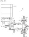
Fig. 3] Fig. 3 is a vertical sectional view of a duplex pump (liquid-delivering device) applied to the first and second embodiments of the present invention. - [
Fig. 4] Fig. 4 is a horizontal sectional view of the duplex pump (liquid-delivering device). - [
Fig. 5] Fig. 5 is a vertical sectional view of an ultrafiltration pump applied to the first and second embodiments of the present invention. - [
Fig. 6] Fig. 6 is a diagram illustrating an ultrafiltration pump according to another embodiment applied to the blood purification apparatus. - [
Fig. 7] Fig. 7 is a diagram illustrating an ultrafiltration pump according to yet another embodiment applied to the blood purification apparatus. - [
Fig. 8] Fig. 8 is a graph illustrating a relationship between the operating speed of a plunger and the discharge pressure in the duplex pump (liquid-delivering device) of the blood purification apparatus that undergoes a discharge step accompanied by no control operation for backflow prevention. - [
Fig. 9] Fig. 9 is a graph illustrating a relationship between the operating speed of the plunger and the discharge pressure in the duplex pump (liquid-delivering device) of the blood purification apparatus that undergoes a discharge step accompanied by a control operation for backflow prevention. - [
Fig. 10] Fig. 10 is a graph illustrating the timing of operation of the ultrafiltration pump (at a high ultrafiltration rate) operating with the duplex pump (liquid-delivering device) of the blood purification apparatus that undergoes another control operation for backflow prevention. - [
Fig. 11] Fig. 11 is a graph illustrating the timing of operation of the ultrafiltration pump (at a low ultrafiltration rate) operating with the duplex pump (liquid-delivering device) of the blood purification apparatus that undergoes the other control operation for backflow prevention. - [
Fig. 12] Fig. 12 is a graph illustrating the timing of operation of the ultrafiltration pump (synchronized with the duplex pump) operating with the duplex pump (liquid-delivering device) of the blood purification apparatus that undergoes another control operation for backflow prevention. Description of Embodiments - Embodiments of the present invention will now be described specifically with reference to the drawings.
- A blood purification apparatus according to a first embodiment is applied to a hemodialysis apparatus and basically includes, as illustrated in
Fig. 1 , a blood circuit 3 (including anarterial blood circuit 3a and avenous blood circuit 3b) connected to a dialyzer 5 (a blood purification device), and an apparatus body B including a duplex pump 1 (a liquid-delivering device), anultrafiltration pump 2, acontrol device 7, a dialysate introduction line L1, a dialysate drain line L2, and an ultrafiltration line L3. - The
dialyzer 5 has thereinside blood purification membranes, not illustrated (the present embodiment employs hollow-fiber hemodialysis membranes or hemodiafiltration membranes, but flat hemodialysis membranes are also acceptable). Thedialyzer 5 further has ablood inlet 5a from which blood is introduced thereinto, ablood outlet 5b from which the blood introduced is discharged, adialysate inlet 5c from which dialysate is introduced thereinto, and adialysate outlet 5d from which the dialysate introduced is discharged. The blood introduced from theblood inlet 5a is brought into contact with the dialysate through the hollow-fiber membranes and is thus purified. - The
arterial blood circuit 3a is basically formed of a flexible tube, with one end thereof being connected to theblood inlet 5a of thedialyzer 5, whereby the blood collected from the blood vessel of the patient is introduced into the hollow-fiber membranes provided in thedialyzer 5. Thearterial blood circuit 3a is provided with an arterial puncture needle a at the other end thereof, and ablood pump 4. Theblood pump 4 according to the present embodiment is a peristaltic pump. - As with the
arterial blood circuit 3a, thevenous blood circuit 3b is basically formed of a flexible tube, with one end thereof being connected to theblood outlet 5b of thedialyzer 5, whereby the blood having flowed through the hollow-fiber membranes is discharged. Thevenous blood circuit 3b is provided with a venous puncture needle b at the other end thereof, and an air-trap chamber 6 for bubble removal at a halfway position thereof. Hence, the blood of the patient collected through the arterial puncture needle a flows through thearterial blood circuit 3a to thedialyzer 5 and is purified therein. Then, the blood flows through thevenous blood circuit 3b and is returned into the body of the patient through the venous puncture needle b. - As described above, the blood of the patient extracorporeally circulates through the
blood circuit 3. In this process, blood purification treatment is performed with thedialyzer 5. In this specification, the side of the puncture needle provided for blood removal (blood collection) is referred to as the "arterial" side, and the side of the puncture needle provided for blood return is referred to as the "venous" side. The "arterial" side and the "venous" side are not defined in accordance with which of the artery and the vein is to be the object of puncture. - The
dialysate inlet 5c and thedialysate outlet 5d of thedialyzer 5 receive the respective ends of the dialysate introduction line L1 and the dialysate drain line L2 connected thereto, whereby the dialysate introduced into thedialyzer 5 through the dialysate introduction line L1 is allowed to flow outside the hollow-fiber membranes and to be drained through the dialysate drain line L2 together with waste liquid. That is, the dialysate introduction line L1 allows the dialysate to be introduced into thedialyzer 5, whereas the dialysate drain line L2 allows the waste liquid to be drained from thedialyzer 5. - The apparatus body B includes not only the dialysate introduction line L1 and the dialysate drain line L2 but also the
duplex pump 1, theultrafiltration pump 2, and so forth. Theduplex pump 1 is provided over the dialysate introduction line L1 and the dialysate drain line L2. When activated, theduplex pump 1 causes the dialysate, prepared to have a predetermined concentration, to flow into thedialyzer 5 and the waste liquid to be drained from thedialyzer 5. Theduplex pump 1 may be replaced with a liquid-delivering device of another type (such as a liquid-delivering device including a balance chamber) capable of delivering the dialysate in the dialysate introduction line L1 to thedialyzer 5 while draining the waste liquid from thedialyzer 5. - More specifically, the
duplex pump 1 according to the present embodiment is a pump capable of delivering liquid such that the volume of the dialysate to be introduced into thedialyzer 5 and the volume of the waste liquid to be drained from thedialyzer 5 are substantially equalized. As illustrated inFigs. 3 and4 , theduplex pump 1 includes a supply-side pump chamber 1a, a drain-side pump chamber 1b, a supply-side suction port C1 from which the dialysate is allowed to be taken into the supply-side pump chamber 1a, a supply-side discharge port C2 from which the dialysate in the supply-side pump chamber 1a is allowed to be discharged, a drain-side suction port C3 from which the dialysate is allowed to be taken into the drain-side pump chamber 1b, a drain-side discharge port C4 from which the dialysate in the drain-side pump chamber 1b is allowed to be discharged, a motor M, a plunger N, and check valves (J1 to J4). - The supply-side pump chamber 1a is an accommodation space having a predetermined capacity and allows, with a reciprocating motion of the plunger N, the dialysate taken therein from the supply-side suction port C1 to flow therethrough and to be discharged from the supply-side discharge port C2. The drain-
side pump chamber 1b is also an accommodation space having a predetermined capacity and allows, with the reciprocating motion of the plunger N, the dialysate taken therein from the drain-side suction port C3 to flow therethrough and to be discharged from the drain-side discharge port C4. The supply-side suction port C1 and the supply-side discharge port C2 are connected to a pipe forming the dialysate introduction line L1. The drain-side suction port C3 and the drain-side discharge port C4 are connected to a pipe forming the dialysate drain line L2. - The plunger N is reciprocatable by the motor M with respect to the supply-side pump chamber 1a and the drain-
side pump chamber 1b. The plunger N undergoing the reciprocating motion takes the dialysate into the supply-side pump chamber 1a and into the drain-side pump chamber 1b from the supply-side suction port C1 and from the drain-side suction port C3 respectively, and discharges the thus taken dialysate from the supply-side discharge port C2 and from the drain-side discharge port C4 respectively, thereby delivering the dialysate. - An output shaft Ma of the motor M is provided with a cam member E. The cam member E has a cam portion Ea projecting at a position different from the axis of the output shaft Ma (at a position decentered from the center of rotation). With the motor M and relevant elements being assembled together, the cam member E is positioned in a recess Na provided in the plunger N. The cam portion Ea is provided with a block slider K. When the motor M is activated, the block slider K pushes the plunger N in the lengthwise direction and thus causes the plunger N to reciprocate in the lateral direction in
Fig. 3 . - The check valves (J1 and J2) are each a valve having a function of preventing the backflow of the dialysate by keeping the dialysate flowing in one specific direction. The check valves (J1 and J2) are each provided between the supply-side pump chamber 1a and a flow route of the supply-side suction port C1 and a flow route of the supply-side discharge port C2 respectively. The check valves (J1 and J2) are openable and closable in accordance with changes in the hydraulic pressure in the supply-side pump chamber 1a that occur with the reciprocating motion of the plunger N. The check valves (J1 and J2) that are open allow the dialysate to flow therethrough. The check valves (J1 and J2) that are closed block the dialysate from flowing therethrough.
- Likewise, the check valves (J3 and J4) are each a valve having a function of preventing the backflow of the dialysate by keeping the dialysate flowing in one specific direction. The check valves (J3 and J4) are each provided between the drain-
side pump chamber 1b and a flow route of the drain-side suction port C3 and a flow route of the drain-side discharge port C4 respectively. The check valves (J3 and J4) are openable and closable in accordance with changes in the hydraulic pressure in the drain-side pump chamber 1b that occur with the reciprocating motion of the plunger N. The check valves (J3 and J4) that are open allow the dialysate to flow therethrough. The check valves (J3 and J4) that are closed block the dialysate from flowing therethrough. - Hence, when the motor M is activated, the plunger N is displaced in one direction toward an end (a displacement end Sb) of the drain-
side pump chamber 1b. In this process, the check valve J1 at the supply-side suction port C1 and the check valve J4 at the drain-side discharge port C4 are opened, whereas the check valve J2 at the supply-side discharge port C2 and the check valve J3 at the drain-side suction port C3 are closed. When the plunger N reaches the one end (the displacement end Sb), all of the check valves (J1 to J4) are closed. - Subsequently, the plunger N is displaced in the other direction toward an end (a displacement end Sa) of the supply-side pump chamber 1a. In this process, the check valve J2 at the supply-side discharge port C2 and the check valve J3 at the drain-side suction port C3 are opened, whereas the check valve J1 at the supply-side suction port C1 and the check valve J4 at the drain-side discharge port C4 are closed. When the plunger N reaches the other end (the displacement end Sa), all of the check valves (J1 to J4) are closed. As the plunger N continues to reciprocate, the check valves (J1 to J4) are repeatedly opened and closed as described above.
- Thus, the duplex pump 1 (the liquid-delivering device) according to the present embodiment can deliver the liquid by periodically undergoing a suction step in which the liquid (the dialysate to be introduced into the
dialyzer 5 or the dialysate as waste liquid to be drained from the dialyzer 5) is taken thereinto (i.e. a suction step of taking the dialysate and the waste liquid into the supply-side pump chamber 1a and the drain-side pump chamber 1b respectively) and a discharge step in which the liquid thus taken is discharged (i.e. a discharge step of discharging the dialysate and the waste liquid taken into the supply-side pump chamber 1a and the drain-side pump chamber 1b respectively). - A
control device 7 is, for example, a microcomputer or the like provided in the apparatus body B and is capable of controlling operations of devices provided to elements such as the dialysate introduction line L1 and the dialysate drain line L2: specifically, the opening and closing of any of electromagnetic valves, the opening and closing of any of clamps, operations including the activation and stopping of any of actuators such as theduplex pump 1 and theblood pump 4, and operations including the activation and stopping of theultrafiltration pump 2 at the time of ultrafiltration. - The blood purification apparatus according to the present embodiment illustrated in
Fig. 1 includes the ultrafiltration line L3 one end of which is connected to the dialysate introduction line L1 at a position P1 on the downstream side with respect to theduplex pump 1 and the other end of which is connected to the dialysate introduction line L1 at a position P2 on the upstream side with respect to theduplex pump 1. The ultrafiltration line L3 is provided with theultrafiltration pump 2. That is, the ultrafiltration line L3 forms a flow route extending between the position P1 on the downstream side with respect to the supply-side pump chamber 1a of theduplex pump 1 that is connected to the dialysate introduction line L1 (the position P1 between the supply-side pump chamber 1a and the dialyzer 5) and the position P2 on the upstream side with respect to the supply-side pump chamber 1a, thereby bypassing the supply-side pump chamber 1a of theduplex pump 1. - The
ultrafiltration pump 2 is capable of removing, through thedialyzer 5, water from the blood flowing through theblood circuit 3. As with theduplex pump 1, theultrafiltration pump 2 is a pump capable of delivering liquid by periodically undergoing a suction step of taking in the liquid and a discharge step of discharging the taken liquid. More specifically, as illustrated inFig. 5 , theultrafiltration pump 2 according to the present embodiment includes apump chamber 2a, a suction port C5 from which the dialysate is allowed to be taken into thepump chamber 2a, a discharge port C6 from which the dialysate in thepump chamber 2a is allowed to be discharged, a motor R, acam member 2b, alink mechanism 2c, aplunger 2d, and check valves (Q1 and Q2). - The
pump chamber 2a is an accommodation space having a predetermined capacity and allows, with a reciprocating motion of theplunger 2d, the dialysate taken therein from the suction port C5 to flow therethrough and to be discharged from the discharge port C6. The suction port C5 and the discharge port C6 are connected to a pipe forming the ultrafiltration line L3. Theplunger 2d operates with the driving force of the motor R that is transmitted thereto through thecam member 2b and thelink mechanism 2c, thereby being reciprocatable with respect to thepump chamber 2a. Theplunger 2d undergoing the reciprocating motion takes the dialysate into thepump chamber 2a from the suction port C5 and discharges the thus taken dialysate from the discharge port C6, thereby delivering the dialysate. - An output shaft Ra of the motor R is provided with the
cam member 2b. Thecam member 2b is provided with thelink mechanism 2c. When the motor R is activated, thecam member 2b and thelink mechanism 2c are actuated to push theplunger 2d in the lengthwise direction and thus causes theplunger 2d to reciprocate in the lateral direction inFig. 5 . - The check valves (Q1 and Q2) are each a valve having a function of preventing the backflow of the dialysate by keeping the dialysate flowing in one specific direction. The check valves (Q1 and Q2) are provided to respective flow routes of the suction port C5 and the discharge port C6. The check valves (Q1 and Q2) are openable and closable in accordance with changes in the hydraulic pressure in the
pump chamber 2a that occur with the reciprocating motion of theplunger 2d. The check valves (Q1 and Q2) that are open allow the dialysate to flow therethrough. The check valves (Q1 and Q2) that are closed block the dialysate from flowing therethrough. - Hence, when the motor R is activated, the
plunger 2d is displaced in one direction. In this process, the check valve Q2 at the suction port C5 is opened, whereas the check valve Q1 at the discharge port C6 is closed. When theplunger 2d reaches one end, both of the check valves (Q1 and Q2) are closed. Subsequently, theplunger 2d is displaced in the other direction. In this process, the check valve Q1 at the discharge port C6 is opened, whereas the check valve Q2 at the suction port C5 is closed. - When the
plunger 2d reaches the other end, both of the check valves (Q1 and Q2) are closed. As theplunger 2d continues to reciprocate, the check valves (Q1 and Q2) are repeatedly opened and closed as described above. Thus, theultrafiltration pump 2 according to the present embodiment can deliver the dialysate by periodically undergoing a suction step of taking in the dialysate and a discharge step of discharging the taken dialysate. - The
ultrafiltration pump 2 according to the present embodiment is connected to the ultrafiltration line L3. When activated at the time of ultrafiltration, theultrafiltration pump 2 draws the dialysate in the dialysate introduction line L1 through the ultrafiltration line L3, thereby making the volume of the dialysate to be introduced into thedialyzer 5 smaller than the volume of the waste liquid to be drained from thedialyzer 5. Thus, ultrafiltration can be implemented. - More specifically, the
duplex pump 1 operates such that the volume of the dialysate to be introduced into thedialyzer 5 and the volume of the waste liquid to be drained from thedialyzer 5 are substantially equalized. Therefore, when theultrafiltration pump 2 is activated and the dialysate flowing toward thedialyzer 5 is drawn through the ultrafiltration line L3, the volume of the dialysate to be introduced into thedialyzer 5 is reduced. Consequently, the volume of the waste liquid to be drained from thedialyzer 5 becomes relatively greater. Hence, water contained in the blood is drained together with the waste liquid by a volume corresponding to the difference from the volume of the dialysate to be introduced into thedialyzer 5. Thus, ultrafiltration is implemented. - In addition, the blood purification apparatus according to the present embodiment is capable of selectively operating in a treatment mode called "ECUM" (extracorporeal ultrafiltration method) (ultrafiltration treatment) in which ultrafiltration alone is performed without causing the dialysate to flow through the
dialyzer 5. If the "ECUM" mode is selected, the duplex pump 1 (the liquid-delivering device) and theultrafiltration pump 2 operate such that the volume of liquid delivery by theduplex pump 1 and the volume of liquid delivery by theultrafiltration pump 2 are substantially equalized. Therefore, ultrafiltration can be performed without introducing the dialysate into thedialyzer 5. - According to the present embodiment, the
ultrafiltration pump 2 is capable of performing ultrafiltration by drawing the dialysate in the dialysate introduction line L1 through the ultrafiltration line L3 such that the volume of the dialysate to be introduced into thedialyzer 5 becomes smaller than the volume of the waste liquid to be drained from thedialyzer 5. Therefore, the waste liquid is prevented from flowing through theultrafiltration pump 2 during ultrafiltration so that the performance and accuracy of ultrafiltration can be maintained over a long period. In particular, the other end of the ultrafiltration line L3 according to the present embodiment is connected to the dialysate introduction line L1 at a position (the position P2) on the upstream side with respect to the duplex pump 1 (the liquid-delivering device). Therefore, the dialysate drawn through the ultrafiltration line L3 during ultrafiltration can be returned to the dialysate introduction line L1. Thus, the dialysate can be used efficiently. - Furthermore, if the duplex pump 1 (the liquid-delivering device) and the
ultrafiltration pump 2 are operated such that the volume of liquid delivery by theduplex pump 1 and the volume of liquid delivery by theultrafiltration pump 2 are substantially equalized, ultrafiltration can be performed without introducing the dialysate into thedialyzer 5. Therefore, while the waste liquid is prevented from flowing through theultrafiltration pump 2 so that the performance and accuracy of ultrafiltration can be maintained over a long period, ultrafiltration alone can be performed without introducing the dialysate into the dialyzer 5 (the "ECUM" mode can be selected). - Now, a second embodiment of the present invention will be described.
- As with the case of the first embodiment, a blood purification apparatus according to the present embodiment is applied to a hemodialysis apparatus and basically includes, as illustrated in
Fig. 2 , a blood circuit 3 (including anarterial blood circuit 3a and avenous blood circuit 3b) connected to a dialyzer 5 (a blood purification device), and an apparatus body B including a duplex pump 1 (a liquid-delivering device), anultrafiltration pump 2, acontrol device 7, a dialysate introduction line L1, a dialysate drain line L2, and an ultrafiltration line L4. Elements that are the same as those described in the first embodiment are denoted by corresponding ones of the reference numerals, and detailed description of such elements is omitted. - The blood purification apparatus according to the present embodiment illustrated in
Fig. 2 includes the ultrafiltration line L4 one end of which is connected to the dialysate introduction line L1 at the position P1 on the downstream side with respect to theduplex pump 1 and the other end of which is connected to the dialysate drain line L2 at a position P3 on the downstream side with respect to theduplex pump 1. The ultrafiltration line L4 is provided with theultrafiltration pump 2. That is, the ultrafiltration line L4 forms a flow route extending between the position P1 on the downstream side with respect to the supply-side pump chamber 1a of theduplex pump 1 that is connected to the dialysate introduction line L1 (the position P1 between the supply-side pump chamber 1a and the dialyzer 5) and the position P3 on the downstream side with respect to the drain-side pump chamber 1b of theduplex pump 1 that is connected to the dialysate drain line L2. - The
ultrafiltration pump 2 is capable of removing, through thedialyzer 5, water from the blood flowing in theblood circuit 3. As with theduplex pump 1, theultrafiltration pump 2 is a pump capable of delivering liquid by periodically undergoing a suction step of taking in the liquid and a discharge step of discharging the taken liquid. Theultrafiltration pump 2 according to the present embodiment is connected to the ultrafiltration line L4. When activated at the time of ultrafiltration, theultrafiltration pump 2 draws the dialysate in the dialysate introduction line L1 through the ultrafiltration line L4, thereby making the volume of the dialysate to be introduced into thedialyzer 5 smaller than the volume of the waste liquid to be drained from thedialyzer 5. Thus, ultrafiltration can be implemented. - More specifically, the
duplex pump 1 operates such that the volume of the dialysate to be introduced into thedialyzer 5 and the volume of the waste liquid to be drained from thedialyzer 5 are substantially equalized. Therefore, when theultrafiltration pump 2 is activated and the dialysate flowing toward thedialyzer 5 is drawn through the ultrafiltration line L4, the volume of the dialysate to be introduced into thedialyzer 5 is reduced. Consequently, the volume of the waste liquid to be drained from thedialyzer 5 becomes relatively greater. Hence, water contained in the blood is drained together with the waste liquid by a volume corresponding to the difference from the volume of the dialysate to be introduced into thedialyzer 5. Thus, ultrafiltration is implemented. - In addition, as with the case of the first embodiment, the blood purification apparatus according to the present embodiment is capable of selectively operating in a treatment mode called "ECUM" (extracorporeal ultrafiltration method) (ultrafiltration treatment) in which ultrafiltration alone is performed without causing the dialysate to flow through the
dialyzer 5. If the "ECUM" mode is selected, the duplex pump 1 (the liquid-delivering device) and theultrafiltration pump 2 operate such that the volume of liquid delivery by theduplex pump 1 and the volume of liquid delivery by theultrafiltration pump 2 are substantially equalized. Therefore, ultrafiltration can be performed without introducing the dialysate into thedialyzer 5. In the treatment performed in the "ECUM" mode, diffusion with thedialyzer 5 is not performed, and the removal of solutes from the blood is avoided. Consequently, the drop in blood pressure can be suppressed. - According to the present embodiment, the
ultrafiltration pump 2 is capable of performing ultrafiltration by drawing the dialysate in the dialysate introduction line L1 through the ultrafiltration line L4, thereby making the volume of the dialysate to be introduced into thedialyzer 5 smaller than the volume of the waste liquid to be drained from thedialyzer 5. Therefore, the waste liquid is prevented from flowing through theultrafiltration pump 2 during ultrafiltration so that the performance and accuracy of ultrafiltration can be maintained over a long period. In particular, the other end of the ultrafiltration line L4 according to the present embodiment is connected to the dialysate drain line L2 at a position (the position P3) on the downstream side with respect to the duplex pump 1 (the liquid-delivering device). Therefore, the dialysate drawn through the ultrafiltration line L4 during ultrafiltration can be drained to the outside of the apparatus through the dialysate drain line L2. - Furthermore, if the duplex pump 1 (the liquid-delivering device) and the
ultrafiltration pump 2 are operated such that the volume of liquid delivery by theduplex pump 1 and the volume of liquid delivery by theultrafiltration pump 2 are substantially equalized, ultrafiltration can be performed without introducing the dialysate into thedialyzer 5. Therefore, while the waste liquid is prevented from flowing through theultrafiltration pump 2 so that the performance and accuracy of ultrafiltration can be maintained over a long period, ultrafiltration alone can be performed without introducing the dialysate into the dialyzer 5 (the "ECUM" mode can be selected). - The
ultrafiltration pump 2 according to each of the first and second embodiments may be replaced with an ultrafiltration pump 2' illustrated inFig. 6 or anultrafiltration pump 2" illustrated inFig. 7 . As illustrated inFigs. 6 and 7 , the ultrafiltration pumps 2' and 2" each include achamber 8 having compartments D1 and D2 separated from each other by adiaphragm 8a, anair pump 9 such as a peristaltic pump or a diaphragm pump, a flow route L5 one end of which is connected to the ultrafiltration line L3 and the other end of which is connected to the compartment D1 of thechamber 8, and a flow route L6 provided with theair pump 9 and one end of which is connected to the compartment D2 of thechamber 8. The other end of the flow route L6 is open to the atmosphere. The ultrafiltration pumps 2' and 2" are each connected to the ultrafiltration line L3 according to the first embodiment but may each be connected to the ultrafiltration line L4 according to the second embodiment. - The ultrafiltration pump 2' is connected to the ultrafiltration line L3 and is provided with, as illustrated in
Fig. 6 , an electromagnetic valve V1a (or another clamping device) at a position on the upstream side (the right side in the drawing) with respect to a position P4 where the ultrafiltration line L3 is connected to the flow route L5, and an electromagnetic valve V1b (or another clamping device) at a position on the downstream side (the left side in the drawing) with respect to the position P4. When the ultrafiltration pump 2' is activated, the electromagnetic valve V1a is opened, whereas the electromagnetic valve V1b is closed. Furthermore, theair pump 9 releases air in the compartment D2 to the atmosphere. Consequently, the dialysate at the position P1 is introduced into the compartment D1. - Subsequently, when the compartment D1 is filled with the dialysate (or when the amount of dialysate exceeds a predetermined level), the electromagnetic valve V1a is closed, whereas the electromagnetic valve V1b is opened. Furthermore, the
air pump 9 sends air into the compartment D2. Consequently, the dialysate in the compartment D1 is delivered to the position P2. As the above process is repeated, the dialysate in the dialysate introduction line L1 can be drawn through the ultrafiltration line L3. Accordingly, the volume of the dialysate to be introduced into thedialyzer 5 can be made smaller than the volume of the waste liquid to be drained from thedialyzer 5. Thus, ultrafiltration can be implemented. - The
ultrafiltration pump 2" is connected to the ultrafiltration line L3 and is provided with, as illustrated inFig. 7 , a check valve V2a at a position on the upstream side (the right side in the drawing) with respect to the position P4 where the ultrafiltration line L3 is connected to the flow route L5, and a check valve V2b at a position on the downstream side (the left side in the drawing) with respect to the position P4. When theultrafiltration pump 2" is activated, theair pump 9 releases air in the compartment D2 to the atmosphere. Consequently, the dialysate at the position P1 is introduced into the compartment D1. In this state, the check valve V2a allows liquid to flow therethrough, whereas the check valve V2b blocks liquid from flowing therethrough. - Subsequently, when the compartment D1 is filled with the dialysate (or when the amount of dialysate exceeds a predetermined level), the
air pump 9 sends air into the compartment D2. Consequently, the dialysate in the compartment D1 is delivered to the position P2. In this state, the check valve V2a blocks liquid from flowing therethrough, whereas the check valve V2b allows liquid to flow therethrough. As the above process is repeated, the dialysate in the dialysate introduction line L1 can be drawn through the ultrafiltration line L3. Accordingly, the volume of the dialysate to be introduced into thedialyzer 5 can be made smaller than the volume of the waste liquid to be drained from thedialyzer 5. Thus, ultrafiltration can be implemented. - Now, a method of preventing the backflow of the dialysate from the
dialyzer 5 into the dialysate introduction line L1 in the blood purification apparatus including the ultrafiltration line L3 or L4 as in the first or second embodiment will be described. - As described above, the duplex pump 1 (or the ultrafiltration pump 2) in this case is a pump capable of delivering liquid by periodically undergoing a suction step of taking in the liquid and a discharge step of discharging the taken liquid, and is capable of delivering the liquid while maintaining the volume of liquid (dialysate) discharge in the discharge step at a predetermined level by increasing the pressure of liquid discharge in an early stage and in a late stage of the discharge step while reducing the pressure of liquid discharge in an intermediate stage between the two stages.
- For example, when the motor M (see
Fig. 3 ) is activated normally (a case of a graph α1 where the operating speed is constant), as illustrated inFig. 8 , the discharge pressure generated in the discharge step undergone by theduplex pump 1 changes with the angle of rotation of the motor M in such a manner as to form a gentle parabolic curve as represented by a graph β1. In such a case, the discharge pressure of theduplex pump 1 stays low for a relatively long period. If theultrafiltration pump 2 undergoes the suction step while the discharge pressure of theduplex pump 1 is low and if the suction pressure of theultrafiltration pump 2 is greater than the discharge pressure of theduplex pump 1, the dialysate flows backward from thedialyzer 5. Note that, in the drawing, the graph α1 represents changes in speed (speed of rotation), and the graph β1 represents changes in pressure. - To avoid the backflow, the present embodiment employs a method illustrated in
Fig. 9 in which the operating speed of the motor M is increased (the speed of the plunger N is made relatively high) as represented by a graph α2 in the early stage (a period from the start to a point after a predetermined time from the start) and in the late stage (a period from a point before a predetermined time from the end to the end) of the discharge step undergone by theduplex pump 1, whereas the operating speed of the motor M is reduced (the speed of the plunger N is made relatively low) in the intermediate stage. Note that, in the drawing, a graph α2 represents changes in speed (speed of rotation), and the graph β2 represents changes in pressure. - As represented by the graph β2, since the pressure of liquid discharge is increased in the early stage and in the late stage of the discharge step but is reduced in the intermediate stage, the liquid can be delivered while the volume of liquid discharge in the discharge step is maintained at a predetermined level. Such a configuration can reduce the probability that the
ultrafiltration pump 2 may undergo the suction step while the discharge pressure in the discharge step undergone by the duplex pump 1 (the liquid-delivering device) is low. Accordingly, the probability that the dialysate introduced into the blood purification device flows backward into the dialysate introduction line L1 can be reduced. - Now, another method of preventing the backflow of the dialysate from the
dialyzer 5 into the dialysate introduction line L1 in the blood purification apparatus including the ultrafiltration line L3 or L4 as in the first or second embodiment will be described. - As described above, the duplex pump 1 (and the ultrafiltration pump 2) in this case is a pump capable of delivering liquid by periodically undergoing a suction step of taking in the liquid and a discharge step of discharging the taken liquid. Furthermore, as illustrated in
Figs. 10 and 11 , theultrafiltration pump 2 operates (is electrically turned on) only in a period T where theduplex pump 1 is undergoing the discharge step. - In particular, in the backflow-preventing method according to the present embodiment, the
ultrafiltration pump 2 operates on condition that the pressure of liquid (dialysate) discharge in the discharge step undergone by the duplex pump 1 (the liquid-delivering device) exceeds a predetermined value ("d" inFigs. 10 and 11 ) . For example, when the ultrafiltration rate is high, as illustrated inFig. 10 , theultrafiltration pump 2 operates within the period T where the discharge pressure of the duplex pump 1 (the pressure at the position P1 illustrated inFigs. 1, 2 ) is higher than the value d, particularly over a period T1 where the discharge pressure (the pressure at the position P1) is higher than a value d1. When the ultrafiltration rate is low, as illustrated inFig. 11 , theultrafiltration pump 2 operates within the period T where the discharge pressure of the duplex pump 1 (the pressure at the position P1 illustrated inFigs. 1, 2 ) is higher than the value d, particularly over a period T2 where the discharge pressure (the pressure at the position P1) is higher than a value d2 (d1 < d2) . - In the backflow-preventing method according to the present embodiment, the
ultrafiltration pump 2 operates only in the period where the duplex pump 1 (the liquid-delivering device) is undergoing the discharge step. Therefore, activation of theultrafiltration pump 2 while theduplex pump 1 is undergoing the suction step can be assuredly avoided. Accordingly, the dialysate introduced into the dialyzer 5 (the blood purification device) can be prevented from flowing backward into the dialysate introduction line L1. In particular, if theultrafiltration pump 2 is operated on condition that the pressure of liquid discharge in the discharge step undergone by theduplex pump 1 exceeds a predetermined value, the dialysate introduced into thedialyzer 5 can be more assuredly prevented from flowing backward into the dialysate introduction line L1. - Now, yet another method of preventing the backflow of the dialysate from the
dialyzer 5 into the dialysate introduction line L1 in the blood purification apparatus including the ultrafiltration line L3 or L4 as in the first or second embodiment will be described. - As described above, the duplex pump 1 (the liquid-delivering device) and the
ultrafiltration pump 2 in this case include the respective plungers (N and 2d) with which the suction step and the discharge step are implemented. Furthermore, the blood purification apparatus includes a synchronization device (not illustrated) that couples the plunger N of theduplex pump 1 and theplunger 2d of theultrafiltration pump 2 to each other for synchronous operation with the aid of elements such as a cam and a link. Furthermore, the synchronization device operates such that theultrafiltration pump 2 undergoes the suction step while theduplex pump 1 is undergoing the discharge step, and theultrafiltration pump 2 undergoes the discharge step while theduplex pump 1 is undergoing the suction step. - For example, in
Fig. 12 where the horizontal axis represents time while the vertical axis represents the flow volume of the dialysate at the position P1, the change in the flow volume of theduplex pump 1 is graphed as W1, and the change in the flow volume of theultrafiltration pump 2 is graphed as W2. In this case, the synchronization device operates such that theultrafiltration pump 2 undergoes the suction step while theduplex pump 1 is undergoing the discharge step, and theultrafiltration pump 2 undergoes the discharge step while theduplex pump 1 is undergoing the suction step. In the drawing, a part of the vertical axis above thepoint 0 represents the volume of the flow from the position P1 toward thedialyzer 5, and a part of the vertical axis below thepoint 0 represents the volume of the flow from the position P1 toward the ultrafiltration line L3. - In this method, the
ultrafiltration pump 2 can be assuredly prevented from undergoing the discharge step while the duplex pump 1 (the liquid-delivering device) is undergoing the suction step. Accordingly, the dialysate introduced into the dialyzer 5 (the blood purification device) can be much more assuredly prevented from flowing backward into the dialysate introduction line L1. The synchronization device is not limited to a device that physically couples the plungers with elements such as a cam and a link, and may be a device that electrically controls the plungers to operate synchronously. - According to the above embodiment, the liquid-delivering device is the
duplex pump 1 that includes the supply-side pump chamber 1a connected to the dialysate introduction line L1 and being capable of accommodating and discharging the dialysate from and into the dialysate introduction line L1, and the drain-side pump chamber 1b connected to the dialysate drain line L2 and being capable of taking in and accommodating the waste liquid from the dialysate drain line L2. Furthermore, the liquid-delivering device delivers the liquid such that the volume of discharge from the supply-side pump chamber 1a and the volume of suction into the drain-side pump chamber 1b are substantially equalized. Furthermore, one end of the ultrafiltration line (L3 or L4) is connected to the dialysate introduction line L1 at a position between the supply-side pump chamber 1a and the point of connection of the dialysate introduction line L1 to the dialyzer 5 (the blood purification device). Therefore, while the dialysate and the waste liquid are delivered by theduplex pump 1, the waste liquid is prevented from flowing through the ultrafiltration pump during ultrafiltration so that the performance and accuracy of ultrafiltration can be maintained over a long period. - While some embodiments have been described above, the present invention is not limited thereto. For example, as long as one end of the ultrafiltration line (L3 or L4) is connected to the dialysate introduction line L1 at a position on the downstream side with respect to the duplex pump 1 (the liquid-delivering device), the other end of the ultrafiltration line (L3, L4) may be connected to a position other than the dialysate introduction line L1 or the dialysate drain line L2 (for example, the dialysate may be discharged directly to the outside of the apparatus body B). Moreover, while the duplex pump 1 (the liquid-delivering device) and the
ultrafiltration pump 2 according to any of the above embodiments are each a pump capable of delivering liquid by periodically undergoing a suction step of taking in the liquid and a discharge step of discharging the taken liquid, one of or both of the two may skip the suction step and the discharge step in delivering the liquid. - The present invention is applicable to any blood purification apparatus, including those having other additional functions and so forth, as long as the following are satisfied: the blood purification apparatus includes an ultrafiltration line one end of which is connected to a dialysate introduction line at a position on the downstream side with respect to a liquid-delivering device, the ultrafiltration line is provided with an ultrafiltration pump, and the ultrafiltration pump is capable of performing ultrafiltration by drawing dialysate in the dialysate introduction line through the ultrafiltration line such that the volume of the dialysate to be introduced into a blood purification device becomes smaller than the volume of waste liquid to be drained from the blood purification device.
-
- 1
- duplex pump (liquid-delivering device)
- 1a
- supply-side pump chamber
- 1b
- drain-side pump chamber
- 2
- ultrafiltration pump
- 2a
- pump chamber
- 2b
- cam member
- 2c
- link mechanism
- 2d
- plunger
- 3
- blood circuit
- 3a
- arterial blood circuit
- 3b
- venous blood circuit
- 4
- blood pump
- 5
- dialyzer (blood purification device)
- 6
- air-trap chamber
- 7
- control device
- 8
- chamber
- 9
- air pump
- B
- apparatus body
- L1
- dialysate introduction line
- L2
- dialysate drain line
- L3
- ultrafiltration line
- L4
- ultrafiltration line
- M
- motor
- Ma
- output shaft
- R
- motor
- Ra
- output shaft
- E
- cam member
- Ea
- cam portion
- N
- plunger
- Na
- recess
- K
- block slider
- J1 to J4
- check valve
- Q1, Q2
- check valve
- C1
- supply-side suction port
- C2
- supply-side discharge port
- C3
- drain-side suction port
- C4
- drain-side discharge port
- C5
- suction port
- C6
- discharge port
Claims (9)
- A blood purification apparatus comprising:a blood circuit including an arterial blood circuit and a venous blood circuit and through which blood of a patient is allowed to extracorporeally circulate;a blood purification device connected to the arterial blood circuit and to the venous blood circuit and that purifies the blood flowing through the blood circuit;a dialysate introduction line that allows dialysate to be introduced into the blood purification device;a dialysate drain line that allows waste liquid to be drained from the blood purification device;a liquid-delivering device capable of delivering liquid such that a volume of the dialysate to be introduced into the blood purification device and a volume of the waste liquid to be drained from the blood purification device are substantially equalized; andan ultrafiltration pump capable of removing, through the blood purification device, water from the blood flowing through the blood circuit,wherein the blood purification apparatus includes an ultrafiltration line one end of which is connected to the dialysate introduction line at a position on a downstream side with respect to the liquid-delivering device, wherein the ultrafiltration line is provided with an ultrafiltration pump, and wherein the ultrafiltration pump is capable of performing ultrafiltration by drawing the dialysate in the dialysate introduction line through the ultrafiltration line such that the volume of the dialysate to be introduced into the blood purification device becomes smaller than the volume of the waste liquid to be drained from the blood purification device.
- The blood purification apparatus according to Claim 1, wherein an other end of the ultrafiltration line is connected to the dialysate introduction line at a position on an upstream side with respect to the liquid-delivering device.
- The blood purification apparatus according to Claim 1, wherein an other end of the ultrafiltration line is connected to the dialysate drain line at a position on a downstream side with respect to the liquid-delivering device.
- The blood purification apparatus according to any of Claims 1 to 3, wherein ultrafiltration is performable without introducing the dialysate into the blood purification device if the liquid-delivering device and the ultrafiltration pump are operated such that a volume of liquid delivery by the liquid-delivering device and a volume of liquid delivery by the ultrafiltration pump are substantially equalized.
- The blood purification apparatus according to any of Claims 1 to 4, wherein the liquid-delivering device and the ultrafiltration pump are each a pump capable of delivering liquid by periodically undergoing a suction step of taking in the liquid and a discharge step of discharging the taken liquid, and wherein the ultrafiltration pump operates only in a period where the liquid-delivering device is undergoing the discharge step.
- The blood purification apparatus according to Claim 5, wherein the ultrafiltration pump operates on condition that a pressure of liquid discharge in the discharge step undergone by the liquid-delivering device exceeds a predetermined value.
- The blood purification apparatus according to Claim 5 or 6, wherein the blood purification apparatus includes a synchronization device capable of synchronizing the suction step and the discharge step undergone by the liquid-delivering device and the ultrafiltration pump such that the ultrafiltration pump undergoes the suction step while the liquid-delivering device is undergoing the discharge step, and the ultrafiltration pump undergoes the discharge step while the liquid-delivering device is undergoing the suction step.
- The blood purification apparatus according to any of Claims 1 to 7, wherein the liquid-delivering device or the ultrafiltration pump is a pump capable of delivering liquid by periodically undergoing a suction step of taking in the liquid and a discharge step of discharging the taken liquid, and is capable of delivering the liquid while maintaining a volume of liquid discharge in the discharge step at a predetermined level by increasing a pressure of liquid discharge in an early stage and in a late stage of the discharge step while reducing the pressure of liquid discharge in an intermediate stage between the two stages.
- The blood purification apparatus according to any of Claims 1 to 8, wherein the liquid-delivering device is a duplex pump that includes a supply-side pump chamber connected to the dialysate introduction line and being capable of accommodating and discharging the dialysate from and into the dialysate introduction line, and a drain-side pump chamber connected to the dialysate drain line and being capable of taking in and accommodating the waste liquid from the dialysate drain line; wherein the liquid-delivering device delivers the liquid such that a volume of discharge from the supply-side pump chamber and a volume of suction into the drain-side pump chamber are substantially equalized; and wherein one end of the ultrafiltration line is connected to the dialysate introduction line at a position between the supply-side pump chamber and a point of connection of the dialysate introduction line to the blood purification device.
Applications Claiming Priority (2)
| Application Number | Priority Date | Filing Date | Title |
|---|---|---|---|
| JP2017120203A JP6873838B2 (en) | 2017-06-20 | 2017-06-20 | Blood purification device |
| PCT/JP2018/023480 WO2018235870A1 (en) | 2017-06-20 | 2018-06-20 | Blood purification device |
Publications (3)
| Publication Number | Publication Date |
|---|---|
| EP3643339A1 true EP3643339A1 (en) | 2020-04-29 |
| EP3643339A4 EP3643339A4 (en) | 2021-04-07 |
| EP3643339B1 EP3643339B1 (en) | 2023-04-19 |
Family
ID=64735712
Family Applications (1)
| Application Number | Title | Priority Date | Filing Date |
|---|---|---|---|
| EP18821565.1A Active EP3643339B1 (en) | 2017-06-20 | 2018-06-20 | Blood purification apparatus |
Country Status (5)
| Country | Link |
|---|---|
| US (1) | US11931498B2 (en) |
| EP (1) | EP3643339B1 (en) |
| JP (1) | JP6873838B2 (en) |
| CN (1) | CN110769869B (en) |
| WO (1) | WO2018235870A1 (en) |
Family Cites Families (26)
| Publication number | Priority date | Publication date | Assignee | Title |
|---|---|---|---|---|
| DE3133177A1 (en) * | 1981-08-19 | 1983-03-10 | Baurmeister, Ulrich, Dr.-Ing., 1000 Berlin | Hermetically encapsulated centrifugal pump for the gentle delivery of fluids |
| US4747950A (en) * | 1983-12-16 | 1988-05-31 | Cd Medical, Inc. | Method and apparatus for controlled ultrafiltration during hemodialysis |
| DE3641843A1 (en) * | 1986-12-08 | 1988-06-16 | Fresenius Ag | HAEMODIALYSIS DEVICE WITH STERILIZER |
| JP2769514B2 (en) * | 1989-03-13 | 1998-06-25 | 株式会社三陽電機製作所 | Water removal control device for hemodialysis machine |
| JPH0630201Y2 (en) * | 1989-03-13 | 1994-08-17 | 株式会社三陽電機製作所 | Water removal controller for hemodialysis machine |
| US5589070A (en) * | 1993-07-16 | 1996-12-31 | Cobe Laboratories, Inc. | Method and apparatus for cleaning a dialysate circuit downstream of a dialyzer |
| JP2735770B2 (en) * | 1993-09-17 | 1998-04-02 | 日機装株式会社 | Dialysis device water removal control monitoring device |
| JP3907866B2 (en) * | 1999-05-19 | 2007-04-18 | 有限会社 北九州生命情報科学院 | Automatic hemodialysis machine |
| DE10100146B4 (en) * | 2001-01-03 | 2004-11-25 | Fresenius Medical Care Deutschland Gmbh | Dialysis machine and method for operating the same |
| JP4250712B2 (en) * | 2002-06-19 | 2009-04-08 | 株式会社北九州バイオフィジックス研究所 | Automatic hemodialysis machine |
| US10537671B2 (en) * | 2006-04-14 | 2020-01-21 | Deka Products Limited Partnership | Automated control mechanisms in a hemodialysis apparatus |
| US10463774B2 (en) * | 2007-02-27 | 2019-11-05 | Deka Products Limited Partnership | Control systems and methods for blood or fluid handling medical devices |
| JP4573860B2 (en) * | 2007-08-22 | 2010-11-04 | 日機装株式会社 | Blood purification equipment |
| JP2009125421A (en) * | 2007-11-27 | 2009-06-11 | Jms Co Ltd | Hemodialysis machine |
| JP5222706B2 (en) * | 2008-12-04 | 2013-06-26 | 日機装株式会社 | Blood purification apparatus and blood flow calculation method thereof |
| JP5301259B2 (en) | 2008-12-09 | 2013-09-25 | 日機装株式会社 | Hemodialysis machine |
| JP5431228B2 (en) * | 2010-03-30 | 2014-03-05 | 日機装株式会社 | Blood purification equipment |
| EP2601985A4 (en) * | 2010-08-05 | 2015-10-07 | Nikkiso Co Ltd | BLOOD PURIFYING DEVICE, AND METHOD FOR FLUID LEAK INSPECTION IN SUCH A DEVICE |
| JP2012192100A (en) * | 2011-03-17 | 2012-10-11 | Nikkiso Co Ltd | Blood purifier |
| SG195155A1 (en) * | 2011-05-24 | 2013-12-30 | Deka Products Lp | Blood treatment systems and methods |
| JP6439350B2 (en) * | 2014-03-04 | 2018-12-19 | ニプロ株式会社 | Blood purification equipment |
| DE102014003619A1 (en) * | 2014-03-13 | 2015-09-17 | Fresenius Medical Care Deutschland Gmbh | Apparatus and method for balancing an inflow and outflow from a medical treatment device |
| JP2016047126A (en) * | 2014-08-27 | 2016-04-07 | 旭化成メディカル株式会社 | Blood purification device |
| US20160136346A1 (en) * | 2014-11-18 | 2016-05-19 | Taebeom Cho | Hemodialysis apparatus |
| EP4129357B1 (en) * | 2015-10-07 | 2024-06-26 | MAQUET Cardiopulmonary GmbH | Medical device |
| JP6159771B2 (en) * | 2015-10-13 | 2017-07-05 | 日機装株式会社 | Blood purification equipment |
-
2017
- 2017-06-20 JP JP2017120203A patent/JP6873838B2/en active Active
-
2018
- 2018-06-20 EP EP18821565.1A patent/EP3643339B1/en active Active
- 2018-06-20 WO PCT/JP2018/023480 patent/WO2018235870A1/en not_active Ceased
- 2018-06-20 CN CN201880040907.7A patent/CN110769869B/en active Active
-
2019
- 2019-12-17 US US16/716,880 patent/US11931498B2/en active Active
Also Published As
| Publication number | Publication date |
|---|---|
| CN110769869B (en) | 2022-03-15 |
| CN110769869A (en) | 2020-02-07 |
| EP3643339B1 (en) | 2023-04-19 |
| US20200121844A1 (en) | 2020-04-23 |
| JP2019000585A (en) | 2019-01-10 |
| US11931498B2 (en) | 2024-03-19 |
| WO2018235870A1 (en) | 2018-12-27 |
| EP3643339A4 (en) | 2021-04-07 |
| JP6873838B2 (en) | 2021-05-19 |
Similar Documents
| Publication | Publication Date | Title |
|---|---|---|
| KR100728522B1 (en) | Blood treatment device and disposable kit for a blood treatment device | |
| KR101076352B1 (en) | Circuits for extracorporeal treatment of blood and flow diverters used therein | |
| CN102939119B (en) | Apparatus for purifying blood and pre-punching method thereof | |
| CN104379186B (en) | Blood purification device and priming method thereof | |
| EP2679257B1 (en) | Blood purification device | |
| CN111372620B (en) | Extracorporeal blood treatment apparatus | |
| EP3511035B1 (en) | Blood purification apparatus | |
| CN101400387A (en) | Method for at least partially draining an extracorporeal blood flow and haemodialysis device for use with said method | |
| JPS63105769A (en) | Method and apparatus for allowing two kinds of liquid for artificial kidney to feed out as continuous flow in same amount by pump | |
| EP3127564A1 (en) | Blood purification device and fluid replacement/priming method for blood purification device | |
| US12083257B2 (en) | Blood purification apparatus | |
| US10532147B2 (en) | Method of flushing an extracorporeal blood circuit | |
| EP0478692A1 (en) | COMBINED HEMOFILTRATION AND HEMODIALYSIS SYSTEM. | |
| EP3643339B1 (en) | Blood purification apparatus | |
| US11992588B2 (en) | Blood hose set, a control device or closed-loop control device, a blood treatment apparatus and a method for the single-needle treatment | |
| US11246969B2 (en) | Apparatus for extracorporeal blood treatment and method for operating an extracorporeal blood treatment apparatus | |
| JP2011206324A (en) | Blood purifying apparatus | |
| US10471200B2 (en) | Blood purification apparatus | |
| CN114728113A (en) | Dialysis machine for performing push-pull dialysis treatment | |
| EP4501370A1 (en) | Blood purification device | |
| EP4327842A1 (en) | Blood purification device | |
| JP7592518B2 (en) | Blood Purification Device | |
| CN120860349A (en) | Blood purifying device | |
| CN117881438A (en) | Blood purification device | |
| WO2022264594A1 (en) | Blood purification device |
Legal Events
| Date | Code | Title | Description |
|---|---|---|---|
| STAA | Information on the status of an ep patent application or granted ep patent |
Free format text: STATUS: THE INTERNATIONAL PUBLICATION HAS BEEN MADE |
|
| PUAI | Public reference made under article 153(3) epc to a published international application that has entered the european phase |
Free format text: ORIGINAL CODE: 0009012 |
|
| STAA | Information on the status of an ep patent application or granted ep patent |
Free format text: STATUS: REQUEST FOR EXAMINATION WAS MADE |
|
| 17P | Request for examination filed |
Effective date: 20200116 |
|
| AK | Designated contracting states |
Kind code of ref document: A1 Designated state(s): AL AT BE BG CH CY CZ DE DK EE ES FI FR GB GR HR HU IE IS IT LI LT LU LV MC MK MT NL NO PL PT RO RS SE SI SK SM TR |
|
| AX | Request for extension of the european patent |
Extension state: BA ME |
|
| DAV | Request for validation of the european patent (deleted) | ||
| DAX | Request for extension of the european patent (deleted) | ||
| A4 | Supplementary search report drawn up and despatched |
Effective date: 20210304 |
|
| RIC1 | Information provided on ipc code assigned before grant |
Ipc: A61M 1/16 20060101AFI20210226BHEP Ipc: A61M 1/34 20060101ALI20210226BHEP |
|
| GRAP | Despatch of communication of intention to grant a patent |
Free format text: ORIGINAL CODE: EPIDOSNIGR1 |
|
| STAA | Information on the status of an ep patent application or granted ep patent |
Free format text: STATUS: GRANT OF PATENT IS INTENDED |
|
| INTG | Intention to grant announced |
Effective date: 20221209 |
|
| RIN1 | Information on inventor provided before grant (corrected) |
Inventor name: MATSUO, SUMIAKI Inventor name: ISHIZAKI, FUMIHIKO |
|
| GRAS | Grant fee paid |
Free format text: ORIGINAL CODE: EPIDOSNIGR3 |
|
| GRAA | (expected) grant |
Free format text: ORIGINAL CODE: 0009210 |
|
| STAA | Information on the status of an ep patent application or granted ep patent |
Free format text: STATUS: THE PATENT HAS BEEN GRANTED |
|
| AK | Designated contracting states |
Kind code of ref document: B1 Designated state(s): AL AT BE BG CH CY CZ DE DK EE ES FI FR GB GR HR HU IE IS IT LI LT LU LV MC MK MT NL NO PL PT RO RS SE SI SK SM TR |
|
| REG | Reference to a national code |
Ref country code: GB Ref legal event code: FG4D |
|
| REG | Reference to a national code |
Ref country code: CH Ref legal event code: EP |
|
| REG | Reference to a national code |
Ref country code: DE Ref legal event code: R096 Ref document number: 602018048677 Country of ref document: DE |
|
| REG | Reference to a national code |
Ref country code: IE Ref legal event code: FG4D |
|
| REG | Reference to a national code |
Ref country code: AT Ref legal event code: REF Ref document number: 1560737 Country of ref document: AT Kind code of ref document: T Effective date: 20230515 |
|
| P01 | Opt-out of the competence of the unified patent court (upc) registered |
Effective date: 20230523 |
|
| REG | Reference to a national code |
Ref country code: SE Ref legal event code: TRGR |
|
| REG | Reference to a national code |
Ref country code: LT Ref legal event code: MG9D |
|
| REG | Reference to a national code |
Ref country code: NL Ref legal event code: MP Effective date: 20230419 |
|
| REG | Reference to a national code |
Ref country code: AT Ref legal event code: MK05 Ref document number: 1560737 Country of ref document: AT Kind code of ref document: T Effective date: 20230419 |
|
| PG25 | Lapsed in a contracting state [announced via postgrant information from national office to epo] |
Ref country code: NL Free format text: LAPSE BECAUSE OF FAILURE TO SUBMIT A TRANSLATION OF THE DESCRIPTION OR TO PAY THE FEE WITHIN THE PRESCRIBED TIME-LIMIT Effective date: 20230419 |
|
| PG25 | Lapsed in a contracting state [announced via postgrant information from national office to epo] |
Ref country code: PT Free format text: LAPSE BECAUSE OF FAILURE TO SUBMIT A TRANSLATION OF THE DESCRIPTION OR TO PAY THE FEE WITHIN THE PRESCRIBED TIME-LIMIT Effective date: 20230821 Ref country code: NO Free format text: LAPSE BECAUSE OF FAILURE TO SUBMIT A TRANSLATION OF THE DESCRIPTION OR TO PAY THE FEE WITHIN THE PRESCRIBED TIME-LIMIT Effective date: 20230719 Ref country code: ES Free format text: LAPSE BECAUSE OF FAILURE TO SUBMIT A TRANSLATION OF THE DESCRIPTION OR TO PAY THE FEE WITHIN THE PRESCRIBED TIME-LIMIT Effective date: 20230419 Ref country code: AT Free format text: LAPSE BECAUSE OF FAILURE TO SUBMIT A TRANSLATION OF THE DESCRIPTION OR TO PAY THE FEE WITHIN THE PRESCRIBED TIME-LIMIT Effective date: 20230419 |
|
| PG25 | Lapsed in a contracting state [announced via postgrant information from national office to epo] |
Ref country code: RS Free format text: LAPSE BECAUSE OF FAILURE TO SUBMIT A TRANSLATION OF THE DESCRIPTION OR TO PAY THE FEE WITHIN THE PRESCRIBED TIME-LIMIT Effective date: 20230419 Ref country code: PL Free format text: LAPSE BECAUSE OF FAILURE TO SUBMIT A TRANSLATION OF THE DESCRIPTION OR TO PAY THE FEE WITHIN THE PRESCRIBED TIME-LIMIT Effective date: 20230419 Ref country code: LV Free format text: LAPSE BECAUSE OF FAILURE TO SUBMIT A TRANSLATION OF THE DESCRIPTION OR TO PAY THE FEE WITHIN THE PRESCRIBED TIME-LIMIT Effective date: 20230419 Ref country code: LT Free format text: LAPSE BECAUSE OF FAILURE TO SUBMIT A TRANSLATION OF THE DESCRIPTION OR TO PAY THE FEE WITHIN THE PRESCRIBED TIME-LIMIT Effective date: 20230419 Ref country code: IS Free format text: LAPSE BECAUSE OF FAILURE TO SUBMIT A TRANSLATION OF THE DESCRIPTION OR TO PAY THE FEE WITHIN THE PRESCRIBED TIME-LIMIT Effective date: 20230819 Ref country code: HR Free format text: LAPSE BECAUSE OF FAILURE TO SUBMIT A TRANSLATION OF THE DESCRIPTION OR TO PAY THE FEE WITHIN THE PRESCRIBED TIME-LIMIT Effective date: 20230419 Ref country code: GR Free format text: LAPSE BECAUSE OF FAILURE TO SUBMIT A TRANSLATION OF THE DESCRIPTION OR TO PAY THE FEE WITHIN THE PRESCRIBED TIME-LIMIT Effective date: 20230720 Ref country code: AL Free format text: LAPSE BECAUSE OF FAILURE TO SUBMIT A TRANSLATION OF THE DESCRIPTION OR TO PAY THE FEE WITHIN THE PRESCRIBED TIME-LIMIT Effective date: 20230419 |
|
| PG25 | Lapsed in a contracting state [announced via postgrant information from national office to epo] |
Ref country code: FI Free format text: LAPSE BECAUSE OF FAILURE TO SUBMIT A TRANSLATION OF THE DESCRIPTION OR TO PAY THE FEE WITHIN THE PRESCRIBED TIME-LIMIT Effective date: 20230419 |
|
| PG25 | Lapsed in a contracting state [announced via postgrant information from national office to epo] |
Ref country code: SK Free format text: LAPSE BECAUSE OF FAILURE TO SUBMIT A TRANSLATION OF THE DESCRIPTION OR TO PAY THE FEE WITHIN THE PRESCRIBED TIME-LIMIT Effective date: 20230419 |
|
| PG25 | Lapsed in a contracting state [announced via postgrant information from national office to epo] |
Ref country code: MC Free format text: LAPSE BECAUSE OF FAILURE TO SUBMIT A TRANSLATION OF THE DESCRIPTION OR TO PAY THE FEE WITHIN THE PRESCRIBED TIME-LIMIT Effective date: 20230419 |
|
| REG | Reference to a national code |
Ref country code: DE Ref legal event code: R097 Ref document number: 602018048677 Country of ref document: DE |
|
| PG25 | Lapsed in a contracting state [announced via postgrant information from national office to epo] |
Ref country code: SM Free format text: LAPSE BECAUSE OF FAILURE TO SUBMIT A TRANSLATION OF THE DESCRIPTION OR TO PAY THE FEE WITHIN THE PRESCRIBED TIME-LIMIT Effective date: 20230419 Ref country code: SK Free format text: LAPSE BECAUSE OF FAILURE TO SUBMIT A TRANSLATION OF THE DESCRIPTION OR TO PAY THE FEE WITHIN THE PRESCRIBED TIME-LIMIT Effective date: 20230419 Ref country code: RO Free format text: LAPSE BECAUSE OF FAILURE TO SUBMIT A TRANSLATION OF THE DESCRIPTION OR TO PAY THE FEE WITHIN THE PRESCRIBED TIME-LIMIT Effective date: 20230419 Ref country code: MC Free format text: LAPSE BECAUSE OF FAILURE TO SUBMIT A TRANSLATION OF THE DESCRIPTION OR TO PAY THE FEE WITHIN THE PRESCRIBED TIME-LIMIT Effective date: 20230419 Ref country code: EE Free format text: LAPSE BECAUSE OF FAILURE TO SUBMIT A TRANSLATION OF THE DESCRIPTION OR TO PAY THE FEE WITHIN THE PRESCRIBED TIME-LIMIT Effective date: 20230419 Ref country code: DK Free format text: LAPSE BECAUSE OF FAILURE TO SUBMIT A TRANSLATION OF THE DESCRIPTION OR TO PAY THE FEE WITHIN THE PRESCRIBED TIME-LIMIT Effective date: 20230419 Ref country code: CZ Free format text: LAPSE BECAUSE OF FAILURE TO SUBMIT A TRANSLATION OF THE DESCRIPTION OR TO PAY THE FEE WITHIN THE PRESCRIBED TIME-LIMIT Effective date: 20230419 |
|
| REG | Reference to a national code |
Ref country code: CH Ref legal event code: PL |
|
| PLBE | No opposition filed within time limit |
Free format text: ORIGINAL CODE: 0009261 |
|
| STAA | Information on the status of an ep patent application or granted ep patent |
Free format text: STATUS: NO OPPOSITION FILED WITHIN TIME LIMIT |
|
| REG | Reference to a national code |
Ref country code: BE Ref legal event code: MM Effective date: 20230630 |
|
| PG25 | Lapsed in a contracting state [announced via postgrant information from national office to epo] |
Ref country code: LU Free format text: LAPSE BECAUSE OF NON-PAYMENT OF DUE FEES Effective date: 20230620 |
|
| 26N | No opposition filed |
Effective date: 20240122 |
|
| REG | Reference to a national code |
Ref country code: IE Ref legal event code: MM4A |
|
| PG25 | Lapsed in a contracting state [announced via postgrant information from national office to epo] |
Ref country code: LU Free format text: LAPSE BECAUSE OF NON-PAYMENT OF DUE FEES Effective date: 20230620 |
|
| PG25 | Lapsed in a contracting state [announced via postgrant information from national office to epo] |
Ref country code: IE Free format text: LAPSE BECAUSE OF NON-PAYMENT OF DUE FEES Effective date: 20230620 |
|
| PG25 | Lapsed in a contracting state [announced via postgrant information from national office to epo] |
Ref country code: IE Free format text: LAPSE BECAUSE OF NON-PAYMENT OF DUE FEES Effective date: 20230620 Ref country code: CH Free format text: LAPSE BECAUSE OF NON-PAYMENT OF DUE FEES Effective date: 20230630 |
|
| PG25 | Lapsed in a contracting state [announced via postgrant information from national office to epo] |
Ref country code: SI Free format text: LAPSE BECAUSE OF FAILURE TO SUBMIT A TRANSLATION OF THE DESCRIPTION OR TO PAY THE FEE WITHIN THE PRESCRIBED TIME-LIMIT Effective date: 20230419 |
|
| PG25 | Lapsed in a contracting state [announced via postgrant information from national office to epo] |
Ref country code: SI Free format text: LAPSE BECAUSE OF FAILURE TO SUBMIT A TRANSLATION OF THE DESCRIPTION OR TO PAY THE FEE WITHIN THE PRESCRIBED TIME-LIMIT Effective date: 20230419 Ref country code: BE Free format text: LAPSE BECAUSE OF NON-PAYMENT OF DUE FEES Effective date: 20230630 |
|
| PG25 | Lapsed in a contracting state [announced via postgrant information from national office to epo] |
Ref country code: BG Free format text: LAPSE BECAUSE OF FAILURE TO SUBMIT A TRANSLATION OF THE DESCRIPTION OR TO PAY THE FEE WITHIN THE PRESCRIBED TIME-LIMIT Effective date: 20230419 |
|
| PG25 | Lapsed in a contracting state [announced via postgrant information from national office to epo] |
Ref country code: BG Free format text: LAPSE BECAUSE OF FAILURE TO SUBMIT A TRANSLATION OF THE DESCRIPTION OR TO PAY THE FEE WITHIN THE PRESCRIBED TIME-LIMIT Effective date: 20230419 |
|
| PGFP | Annual fee paid to national office [announced via postgrant information from national office to epo] |
Ref country code: DE Payment date: 20250618 Year of fee payment: 8 |
|
| PGFP | Annual fee paid to national office [announced via postgrant information from national office to epo] |
Ref country code: GB Payment date: 20250618 Year of fee payment: 8 |
|
| PGFP | Annual fee paid to national office [announced via postgrant information from national office to epo] |
Ref country code: FR Payment date: 20250626 Year of fee payment: 8 |
|
| PG25 | Lapsed in a contracting state [announced via postgrant information from national office to epo] |
Ref country code: CY Free format text: LAPSE BECAUSE OF FAILURE TO SUBMIT A TRANSLATION OF THE DESCRIPTION OR TO PAY THE FEE WITHIN THE PRESCRIBED TIME-LIMIT; INVALID AB INITIO Effective date: 20180620 |
|
| PGFP | Annual fee paid to national office [announced via postgrant information from national office to epo] |
Ref country code: SE Payment date: 20250618 Year of fee payment: 8 |
|
| PG25 | Lapsed in a contracting state [announced via postgrant information from national office to epo] |
Ref country code: HU Free format text: LAPSE BECAUSE OF FAILURE TO SUBMIT A TRANSLATION OF THE DESCRIPTION OR TO PAY THE FEE WITHIN THE PRESCRIBED TIME-LIMIT; INVALID AB INITIO Effective date: 20180620 |
|
| PGFP | Annual fee paid to national office [announced via postgrant information from national office to epo] |
Ref country code: IT Payment date: 20250624 Year of fee payment: 8 |
|
| PG25 | Lapsed in a contracting state [announced via postgrant information from national office to epo] |
Ref country code: TR Free format text: LAPSE BECAUSE OF FAILURE TO SUBMIT A TRANSLATION OF THE DESCRIPTION OR TO PAY THE FEE WITHIN THE PRESCRIBED TIME-LIMIT Effective date: 20230419 |