EP3643216A1 - Cleaning tool - Google Patents
Cleaning tool Download PDFInfo
- Publication number
- EP3643216A1 EP3643216A1 EP18821280.7A EP18821280A EP3643216A1 EP 3643216 A1 EP3643216 A1 EP 3643216A1 EP 18821280 A EP18821280 A EP 18821280A EP 3643216 A1 EP3643216 A1 EP 3643216A1
- Authority
- EP
- European Patent Office
- Prior art keywords
- cleaning
- parts
- axis direction
- handle
- surface part
- Prior art date
- Legal status (The legal status is an assumption and is not a legal conclusion. Google has not performed a legal analysis and makes no representation as to the accuracy of the status listed.)
- Granted
Links
Images






Classifications
-
- A—HUMAN NECESSITIES
- A47—FURNITURE; DOMESTIC ARTICLES OR APPLIANCES; COFFEE MILLS; SPICE MILLS; SUCTION CLEANERS IN GENERAL
- A47L—DOMESTIC WASHING OR CLEANING; SUCTION CLEANERS IN GENERAL
- A47L13/00—Implements for cleaning floors, carpets, furniture, walls, or wall coverings
- A47L13/10—Scrubbing; Scouring; Cleaning; Polishing
- A47L13/20—Mops
- A47L13/24—Frames for mops; Mop heads
- A47L13/254—Plate frames
- A47L13/256—Plate frames for mops made of cloth
-
- A—HUMAN NECESSITIES
- A47—FURNITURE; DOMESTIC ARTICLES OR APPLIANCES; COFFEE MILLS; SPICE MILLS; SUCTION CLEANERS IN GENERAL
- A47L—DOMESTIC WASHING OR CLEANING; SUCTION CLEANERS IN GENERAL
- A47L13/00—Implements for cleaning floors, carpets, furniture, walls, or wall coverings
- A47L13/10—Scrubbing; Scouring; Cleaning; Polishing
- A47L13/20—Mops
- A47L13/24—Frames for mops; Mop heads
- A47L13/254—Plate frames
-
- A—HUMAN NECESSITIES
- A47—FURNITURE; DOMESTIC ARTICLES OR APPLIANCES; COFFEE MILLS; SPICE MILLS; SUCTION CLEANERS IN GENERAL
- A47L—DOMESTIC WASHING OR CLEANING; SUCTION CLEANERS IN GENERAL
- A47L13/00—Implements for cleaning floors, carpets, furniture, walls, or wall coverings
- A47L13/10—Scrubbing; Scouring; Cleaning; Polishing
- A47L13/16—Cloths; Pads; Sponges
-
- A—HUMAN NECESSITIES
- A47—FURNITURE; DOMESTIC ARTICLES OR APPLIANCES; COFFEE MILLS; SPICE MILLS; SUCTION CLEANERS IN GENERAL
- A47L—DOMESTIC WASHING OR CLEANING; SUCTION CLEANERS IN GENERAL
- A47L13/00—Implements for cleaning floors, carpets, furniture, walls, or wall coverings
- A47L13/10—Scrubbing; Scouring; Cleaning; Polishing
- A47L13/20—Mops
- A47L13/24—Frames for mops; Mop heads
-
- A—HUMAN NECESSITIES
- A47—FURNITURE; DOMESTIC ARTICLES OR APPLIANCES; COFFEE MILLS; SPICE MILLS; SUCTION CLEANERS IN GENERAL
- A47L—DOMESTIC WASHING OR CLEANING; SUCTION CLEANERS IN GENERAL
- A47L13/00—Implements for cleaning floors, carpets, furniture, walls, or wall coverings
- A47L13/10—Scrubbing; Scouring; Cleaning; Polishing
- A47L13/20—Mops
- A47L13/24—Frames for mops; Mop heads
- A47L13/254—Plate frames
- A47L13/258—Plate frames of adjustable or foldable type
-
- A—HUMAN NECESSITIES
- A47—FURNITURE; DOMESTIC ARTICLES OR APPLIANCES; COFFEE MILLS; SPICE MILLS; SUCTION CLEANERS IN GENERAL
- A47L—DOMESTIC WASHING OR CLEANING; SUCTION CLEANERS IN GENERAL
- A47L13/00—Implements for cleaning floors, carpets, furniture, walls, or wall coverings
- A47L13/10—Scrubbing; Scouring; Cleaning; Polishing
- A47L13/42—Details
Definitions
- the present invention relates to a cleaning tool.
- a cleaning tool for cleaning a floor surface including a head part to which a member for cleaning such as a cleaning sheet is attached, a handle part for gripping the cleaning tool by a user and a joint part for connecting the head part to the handle part, in which the head part and the handle part are rotatably connected through the joint part.
- the efficiency of cleaning depends on a shape of the head part to which the member for cleaning is attached, therefore, the shape of the head part is variously devised.
- a cleaning tool in which a gap of an approximately triangular shape in cross section is held at a peripheral fringe part of a cleaning head to allow a side part of the cleaning head to be easily deformed and to allow the peripheral fringe part of the cleaning head to easily fit to shapes of edge parts on the floor surface and the like at the time of cleating, thereby cleaning the edge parts on the floor surface and the like efficiently (for example, refer to Patent Literature 1).
- Patent Literature 1 JP-A-2013-34766
- An object of the present invention is to provide a cleaning tool capable of easily cleaning both low places such as the floor surface and high places such as the ceiling and the upper part of the wall.
- a cleaning tool includes a head part to which a member for cleaning is attached and a handle part connected to the head part and for being gripped by a user, in which the head part includes a top surface part forming an upper surface side, to which the handle part is connected and a bottom surface part forming a lower surface side, and the bottom surface part is formed to be freely attachable/detachable with respect to the top surface part.
- the cleaning tool capable of easily cleaning both low places such as the floor surface and high places such as the ceiling and the upper part of the wall.
- a center of gravity may be positioned in a part close to the head part when the handle part is divided into two in a longitudinal direction in a state where the handle part is horizontally laid down both in a state where the bottom surface part is attached to the top surface part and a state where the bottom surface part is not attached to the top surface part in the cleaning tool according to the first aspect.
- the cleaning tool capable of performing cleaning stably both in the state where the bottom surface part is attached and the state where the bottom surface part is not attached.
- the bottom surface part may be formed to have a mass of 30g to 600g in the cleaning tool according to the first aspect or the second aspect.
- easiness in cleaning low places such as the floor surface can be further improved.
- the handle part may be capable of adjusting a length, and a center of gravity position may be capable of being changed by changing the length of the handle part in the cleaning tool according to any one of first to third aspects.
- the cleaning tool capable of adjusting the center of gravity position by adjusting the handle part.
- the handle part may be capable of adjusting a weight
- the center of gravity position may be capable of being changed by changing the weight of the handle part in the cleaning tool according to any one of first to fourth aspects.
- the cleaning tool capable of adjusting the center of gravity position by adjusting the handle part.
- the cleaning tool easily cleaning both low places such as the floor surface and high places such as the ceiling and the upper part of the wall.
- the cleaning tool 100 includes a head part 1 to which a cleaning sheet P is attached, a handle part 2 for grapping the cleaning tool 100 by a user and a joint part 3 connecting the head part 1 to the handle part 2.
- the head part 1 is formed by a top surface part 11 and a bottom surface part 12 made of different materials, and the handle part 2 is attached to an approximately central part on an upper surface of the top surface part 11 through the joint part 3 as shown in Fig. 1 , Fig. 2 and Fig. 3 .
- the top surface part 11 is an approximately rectangular member in plan view being elongated in the Y-axis direction with a size of 50mm to 150mm, preferably 70mm to 120mm in the X-axis direction, and 200mm to 300mm, preferably 220mm to 270mm in the Y-axis direction, which is formed of a hard material such as ABS resin (acrylonitrile, butadiene, styrene copolymer synthetic resin).
- ABS resin acrylonitrile, butadiene, styrene copolymer synthetic resin
- top surface part 11 An upper surface side of the top surface part 11 is formed so that portions close to both end parts in the Y-axis direction are higher and portions close to the central part in the Y-axis direction are lower.
- Raised parts 111 are formed closed to the both end parts in the Y-axis direction and a sunk part 112 is formed close to the central part in the Y-axis direction.
- a lower surface side of the top surface part 11 is connected to an upper surface side of the bottom surface part 12.
- the top surface part 11 is formed to have a mass of 50g to 400g, more preferably, 80g to 300g.
- the raised parts 111 are formed to be raised upward close to the both end parts in the Y-axis direction on the upper surface side of the top surface part 11 in front view as shown in Fig. 2 .
- the raised part 111 is formed so as to gradually raised from the front-and-back direction toward a central part in the X-axis direction so that portions close to the central part in the X-axis direction are highest as shown in Fig. 3 .
- the raised part 111 is formed so that a thickness of the head part 1 is 10mm to 30mm, preferably 15mm to 25mm in the highest portion.
- a thickness of the head part 1 is 10mm to 30mm, preferably 15mm to 25mm in the highest portion.
- the thickness of the head part 1 is lower than 10mm, it is difficult to insert a finger at the time of attaching the sheet to later-described attachment parts 13 and the sheet comes off easily.
- the thickness of the head part 1 is higher than 30mm, entering to places under furniture with low legs such as under a couch or a rack becomes difficult.
- Specific arrangement positions and shapes of the raised parts 111 are not limited to the above can be suitably altered in a condition that the raised parts 111 can be lifted when the handle part 2 climbs over first protruding parts 311.
- the raised parts 111 are formed close to the both end parts in a longitudinal direction of the head part 1 in plan view, however, the present invention is not limited to this, and the raised parts 111 are preferably formed close to both end parts in the same direction as a direction in which two first protruding parts 311 of a later-described first yoke part 31 are aligned.
- the sunk part 112 is formed so as to gradually sink from the raised parts 111 formed at both end parts in a part close to the central part in the Y-axis direction on the upper surface side of the top surface part 11 as shown in Fig. 2 .
- the sunk part 112 is formed so that a thickness of the head part 1 is 15mm or less, preferably 12mm or less in the central part of the top surface part 11 to which the handle part 2 is attached through the joint part 3.
- Ribs 113 protruding downward are formed on the lower surface of the top surface part 11 as shown in Figs. 4A and 4B .
- high ribs 1131 which are largely convex downward are formed close to the central part of the top surface part 11 in plan view and low ribs 1132 which are convex downward in a lower degree than the high ribs 1131 are formed at other parts as shown in Fig. 4A .
- the high ribs 1131 are formed so as to be the same height at all places and the low ribs 1132 are formed so as to be gradually reduced in height from the high ribs 1131 toward fringe part directions on the top surface part 11 as shown in Fig. 4B .
- the high ribs 1131 are formed so as to protrude downward by 0.5mm to 5mm, more preferably, 1mm to 3mm from a lower end portion of a fringe part of the top surface part 11 shown in Fig. 4B .
- the high ribs 1131 are formed in a range of 10% to 90%, more preferably, 50% to 80% with respect to the whole length in the longitudinal direction of the top surface part 11.
- the high ribs 1131 are formed in a range of 10% to 75%, more preferably, 30% to 60% with respect to the whole length in a short-side direction of the top surface part 11.
- the bottom surface part 12 is formed of a softer material than that of the top surface part 11, which can be elastically deformed such as TPE (thermoplastic elastomer) so as to have a rectangular shape approximately congruent with the top surface part 11 in plan view as shown in Fig. 1 , Fig. 2 and Fig. 3 .
- the bottom surface part 12 is formed to have a thickness of 1mm to 10mm, more preferably, 3mm to 4mm in the Z-axis direction.
- the bottom surface part 12 may be formed slightly larger than the top surface part 11.
- a rubber hardness of the material to be used is preferably 60 to 100 (a value measured by a durometer type A (Shore A) standardized by JIS K 6253) from a viewpoint of a dust collection property.
- the bottom surface part 12 is formed so that the upper surface side is approximately parallel to the lower surface side, and is connected to the top surface part 11 on the upper surface side.
- the bottom surface part 12 is formed to have a mass of 30g to 600g, more preferably, 50g to 500g.
- the mass of the bottom surface part 11 is too small, it is necessary for the user to apply a strong force for pressing a floor surface or the like at the time of cleaning low places such as the floor surface with the bottom surface part 12 attached.
- the cleaning tool 1 becomes too heavy and the burden of the user is increased, therefore, both cases are not desirable.
- the bottom surface part 12 is formed to be freely attachable/detachable with respect to the top surface part 11.
- the bottom surface part 12 and the top surface part 11 can be freely attached/detached to/from each other by an arbitrary method such that a concave part is provided on the upper surface side of the bottom surface part 12 and a convex part is provided on the lower surface side of the top surface part 11 so that these parts can be fitted to each other.
- the bottom surface part 12 can be freely attachable/detachable with respect to the top surface part 11 when adopting the following structure.
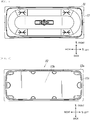
- the bottom surface part 12 is formed to be slightly larger than the top surface part 11 in plan view as shown in Fig. 5 .
- the bottom surface 12 is formed to be larger than the top surface part 11 in plan view by approximately 0.5mm to 5mm, more preferably, 1mm to 3mm in the X-axis direction, 0.5mm to 10mm, more preferably, 1mm to 5mm in the Y-axis direction and 0.5mm t0 20mm, more preferably, 5mm to 15mm at four corners.
- a fringe convex part 12a is formed close to a fringe part in plan view in the bottom surface part 12 so as to extend around a fringe on the upper surface side of the bottom surface 12, and a concave part 12b is formed on an inner peripheral side thereof as shown in Fig. 6 .
- the concave part 12b is formed so as to be approximately congruent with the top surface part 11.
- a rib 12c is formed on a slightly inner side of the fringe convex part 12a in the concave part 12b as shown in Fig. 6 , and the fringe of the top surface part 11 is fitted between the fringe convex part 12a and the rib 12c, thereby allowing both parts to be freely attached/detached to/from each other.
- a level difference between the fringe convex part 12a and the concave part 12b is 0.5mm to 5mm, more preferably, 1mm to 3mm.
- the rib 12c is formed over the entire periphery as shown in Fig. 6 but may be formed at only part thereof.
- the top surface part 11 may be fixed by portions only between these ribs and the fringe convex part 12a.
- a flat surface part 121, short-side direction recessed parts 122 and longitudinal-direction recessed parts 123 are formed.
- the flat surface part 121 is a portion formed in an approximately flat surface shape except for later-described linear ribs 124, which is the portion other than the short-side direction recessed parts 122 and the longitudinal-direction recessed parts 123 on the lower surface side of the bottom surface part 12 as shown in Fig. 7 .
- the bottom surface part 12 corresponds to the entire member formed by an elastically deformable material forming the lower side of the head part 1, and the flat surface part 121 corresponds to a portion formed in the approximately flat surface shape in the lower surface of the bottom surface part 12.
- the short-side direction recessed parts 122 are portions formed to be recessed upward at positions close to both end parts in the short-side direction (X-axis direction) on the lower surface side of the bottom surface part 12 as shown in Fig. 2 and Fig. 7 . According to the parts, portions close to both end parts in the short-side direction (X-axis direction) on the lower surface side of the head part 1 do not closely contact the floor surface, and gaps are generated between the head part 1 and the floor surface at the time of using the cleaning tool 100.
- the short-side direction recessed parts 122 can be formed in an arbitrary shape as far as gaps can be generated with respect to the floor surface on the lower surface side close to the both end parts in the short-side direction (X-axis direction) of the head part 1, however, it is preferable that the short-side direction recessed part 122 is formed so that the lower surface side of the bottom surface part 12 is recessed to the largest degree in a central part in the Y-axis direction of an end part on the front side or the back side of the head part 1 and the recess is reduced as going away from that part to be connected to the flat surface part 121 smoothly.
- the short-side direction recessed part 122 is formed to be recessed upward by 0.1mm to 5mm, more preferably, 0.5mm to 3mm as compared with the flat surface part 121 at the most recessed part.
- the longitudinal-direction recessed parts 123 are portions formed to be recessed upward at positions close to both end parts in the longitudinal direction (Y-axis direction) on the lower surface side of the bottom surface part 12 as shown in Fig. 3 and Fig. 7 . According to the parts, portions close to both end parts in the longitudinal direction (Y-axis direction) on the lower surface side of the head part 1 do not closely contact the floor surface, and gaps are generated between the head part 1 and the floor surface at the time of using the cleaning tool 100.
- the longitudinal direction recessed parts 123 can be formed in an arbitrary shape as far as gaps can be generated with respect to the floor surface on the lower surface side close to the both end parts in the longitudinal direction (Y-axis direction) of the head part 1, however, it is preferable that the longitudinal direction recessed part 123 is formed so that the lower surface side of the bottom surface part 12 is recessed to the largest degree in a central part in the X-axis direction of an end part on the right side or the left side of the head part 1 and the recess is reduced as going away from that part to be connected to the flat surface part 121 smoothly.
- the longitudinal direction recessed part 123 is formed to be recessed upward by 0.1mm to 5mm, more preferably, 0.5mm to 3mm as compared with the flat surface part 121 at the most recessed part.
- the linear ribs 124 which are convex downward are formed so as to be a linear shape in bottom view as shown in Fig. 7 .
- All the linear ribs 124 are formed so as to have the same height in the Z-axis direction, specifically, formed to protrude downward by 0.1mm to 2mm, more preferably, 0.2mm to 1mm.
- Each linear rib is formed in a liner shape with a length of 1mm to 100mm, more preferably, 8mm to 85mm, and with a width of 0.1mm to 2mm, more preferably, 0.2mm to 1.2mm.
- the liner ribs 124 include both ribs formed in the linear shape in bottom view and ribs formed in a curved shape in bottom view.
- the linear ribs 124 includes oblique-line ribs 1241 and rhombus-shaped ribs 1242, and specific arrangement is as follows.
- the oblique-line ribs 1241 are portions other than the rhombus-shaped ribs 1242 in the linear ribs 124, which are formed on the almost entire surface of the flat surface part 121 other than portions where the rhombus-shaped ribs 1242 are formed.
- the oblique-line ribs 1241 are formed in linear shapes inclined toward the center in the Y-axis direction from a direction parallel to the X-axis as coming toward the front direction or the back direction from the central part in the X-axis direction on the bottom surface of the head part 1 in bottom view of the head part 1 as shown in Fig. 7 .
- the rhombus-shaped ribs 1242 are portions where the linear ribs are arranged in an approximately rhombus shape in bottom view as shown in Fig. 7 , which are formed at a central part in the X-axis direction and the Y-axis direction, two places at midpoints between the central part and end parts in the Y-axis direction and four places near four corners on the lower surface of the head part 1 in the flat surface part 121.
- End-part ribs 125 formed in a linear shape along the Y-axis direction are formed in the central part in the X-axis direction on the lower surface side close to the both end parts in the longitudinal direction (Y-axis direction) on the lower surface side of the bottom surface part 12.
- the end-part ribs 125 are formed to have a height of 1mm to 5mm in a lower direction seen from the flat surface part 121.
- the height is lower than 1mm, it is difficult to clean a groove sufficiently, and when the height is higher than 5mm, a possibility of being an obstruction at the time of cleaning a flat surface on the floor surface is increased.
- the end-part ribs 125 are formed to be higher than the linear ribs 124 in the Z-axis direction.
- end-part ribs 125 are formed to have the above height with respect to the flat surface part 121 also in the case where the end-part ribs 125 are formed so as to overlap with the longitudinal direction recessed parts 123 as shown in Fig. 7 .
- the end-part ribs 125 are formed so that a length in the Y-axis direction is 10mm to 50mm, more preferably, 20mm to 30mm and a width in the X-axis direction is 0.1mm to 3mm, more preferably, 0.5mm to 1.5mm.
- end-part ribs 125 are provided, not only the flat surface on the floor surface but also the groove can be cleaned by allowing the ribs to enter the groove on the floor surface.
- end-part protrusions 126 protruding in the Y-axis direction so as to be continued from the end-part ribs 125 are formed as shown in Fig. 1 , Fig. 2 and Fig. 7 .
- the end-part protrusions 126 are formed to protrude to the right direction and the left direction from both end parts in the longitudinal direction (Y-axis direction) of the head part 1 by 0.5mm to 3mm, more preferably, 0.8mm to 2mm.
- Hole parts 127 which are convex upward as shown in Fig. 7 are formed close to the both end parts in the longitudinal direction on the lower surface side of the bottom surface part 12. According to the holes, portions close to the both end parts in the longitudinal direction of the bottom surface part 12 becomes flexible, and the bottom surface part 12 can be attached/detached to/from the top surface part 11 easily.
- Respective holes forming the hole parts 127 are formed so that the size thereof becomes largest at portions close to four corners of the bottom surface part 12 and reduced as coming close to the end-part ribs 125 in bottom view.
- the holes are formed to have lengths of 3mm to 15mm, more preferably, 5mm to 10mm as larger sizes and lengths of 1mm to 5mm, more preferably, 2mm to 4mm as smaller sizes both in the X-axis direction and the Y-axis direction in bottom view.
- the attachment parts 13 are provided close to four corners on the upper surface of the top surface part 11 in plan view as shown in Fig. 1 .
- the attachment parts 13 are holes with claw parts 131 formed of EVA (ethylene-vinyl acetate copolymer) or the like around the holes, which are formed on the raised parts 111 on the upper surface of the top surface part 11.
- EVA ethylene-vinyl acetate copolymer
- the cleaning sheet P can be attached to the head part 1 by pushing the cleaning sheet P to be caught by the claw parts 131.
- the cleaning sheet P is allowed to closely contact the lower surface side of the bottom surface part 12, and portions of the cleaning sheet P protruding from the lower surface side of the bottom surface part 12 are folded to the upper surface side of the top surface part 11 and pushed into the attachment parts 13 provided on the upper surface side of the top surface part 11, thereby attaching the cleaning sheet P to the head part 1.
- the shape of the attachment parts 13 is not limited to the above shape as far as the cleaning sheet P can be attached to the head part 1.
- the handle part 2 is a bar-shaped member used for being gripped by the user at the time of using the cleaning tool 100, including a handle body 21 and a grip part 22 as shown in Fig. 1 .
- the handle part 2 is rotatably connected to the head part 1 through the joint part 3. Explanation will be made by designating the front-and-back direction, the left and right direction and the up-and-down direction in a state where the handle part 2 stands on the head part 1 vertically as shown in Fig. 1 .
- the handle body 21 is a bar-shaped member formed of a hard material such as ABS resin (acrylonitrile, butadiene, styrene copolymer synthetic resin), metal (aluminum, steel, stainless steel), polycarbonate and polypropylene, which is connected to the approximately central part on the upper surface side of the top surface part 11 in the head part 1 through the joint 3 at a lower end, and connected to the grip part 22 at an upper end part.
- ABS resin acrylonitrile, butadiene, styrene copolymer synthetic resin
- metal aluminum, steel, stainless steel
- polycarbonate and polypropylene which is connected to the approximately central part on the upper surface side of the top surface part 11 in the head part 1 through the joint 3 at a lower end, and connected to the grip part 22 at an upper end part.
- the handle body 21 is formed so that a thickness in the front-and-back direction is reduced as compared with a thickness in the left and right direction at a portion close to the lower end part as shown in Fig. 3 . Accordingly, it becomes easy to lay the handle part 2 in a lower state.
- the portion close to the lower end part of the handle body 21 is formed to have the same thickness in the front/back direction and the right/left direction though the effect that the handle part 2 can be easily laid in the lower state is reduced.
- the thickness in the front-and-back direction may be larger than the thickness in the left and right direction by giving weight to, for example, strength of later-described second protruding parts 321.
- the handle body 21 may be formed so as to be divided into plural portions as shown in Fig. 13 .
- the handle body 21 is formed to have a length of 500mm to 1000mm, more preferably, 600mm to 900mm in the Z-axis direction.
- the handle body 21 is formed to have a mass of 50g to 300g, more preferably, 100g to 250g.
- the grip part 22 is a part gripped by the user at the time of using the cleaning tool 100 in the handle part 2, which is connected to the handle body 21 at a lower end part.
- the grip part 22 is formed to have a length of 100mm to 400mm, more preferably, 250mm to 350mm in the Z-axis direction, and to have an approximately circular shape with a diameter of 15mm to 45mm, more preferably, 20mm to 40mm at the thickest part in plan view.
- the grip part 22 is also formed to have a mass of 30g to 200g, more preferably, 50g to 100g.
- the grip part 22 may be formed as a separate member from the handle body 21 as in the embodiment as well as may be integrally formed.
- An upper surface of the grip part 22 is formed to be inclined in one direction with respect to a surface (XY surface) perpendicular to the Z-axis to form an inclined surface 22a as shown in Fig. 8B .
- the inclined surface 22a is formed so as to be inclined by 30 degrees to 80 degrees, more preferably, 40 degrees to 70 degrees with respect to the XY surface.
- a point where the inclined surface 22a is the highest in the Z-axis direction, namely, a front end part of the inclined surface 22a is a tip end 22aa.
- a peripheral surface 22b of the grip part 22, namely, a surface other than the inclined surface 22a on the upper surface and a lower surface connected to the handle body 21 in outer surfaces of the grip part 22 is formed to have a cross-sectional shape in which a diameter is gradually increased toward the upper part except for portions close to the lower end part and the upper end part where the inclined surface 22a is formed as shown in Fig. 8A to Fig. 8B .
- a groove part 22c in which the handle body is concave in a groove shape in the X-axis direction is formed on a side in which the inclined surface 22a is lowered in the Z-axis direction, namely, the back side at an upper part of the grip part 22.
- the groove part 22c is formed to have a depth of 0.5mm to 5mm, more preferably, 1mm to 3mm in the X-axis direction, to have a width of 5mm to 30mm, more preferably, 10mm to 20mm in the Y-axis direction and to have a length of 30mm to 100mm, more preferably, 40mm to 70mm in the Z-axis direction.
- a hole part 22d piercing from the inclined surface 22a to a tip end 22aa side, namely, the front side at the upper part of the peripheral surface 22b is formed at a portion close to the upper end part of the grip part 22 as shown in Fig. 8A to Fig. 8D .
- the hole part 22d includes a depressed part 22da in which the inclined surface 22a is depressed widely in a concave shape and a through hole 22db piercing from the depressed part 22da to the tip end 22aa side at the upper part of the peripheral surface 22b as shown in Fig. 8C and Fig. 8D .
- the hole part 22d is formed so that the through hole 22db is a circular hole in plan view with a diameter of 5mm to 20mm, more preferably, 8mm to 15mm.
- a non-slip part 22e in which the surface of the peripheral surface 22b is raised at plural places in a horizontal linear shape is formed as shown in Fig. 8A and Fig. 8B .
- Plural linear protrusions forming the non-slip part 22e are formed so that each protrusion has a height of 0.1mm to 2mm, more preferably, 0.5mm to 1mm in the X-axis direction, a length of 5mm to 50mm, more preferably, 10mm to 40mm in the Y-axis direction and a width of 1mm to 5mm, more preferably, 1.5mm to 3mm in the Z-axis direction. It is desirable that the linear protrusions forming the non-slip part 22e are formed at intervals of 2mm to 10mm, more preferably, 3mm to 6mm in the Z-axis direction.
- the non-slip part 22e is formed at a position where a tip of a thumb contacts when the user of the cleaning tool 100 grips the grip part 22 as shown in Fig. 9 , specifically, at a position where a distance from the upper end part of the grip part 22 is 30mm to 250mm, more preferably, 70mm to 180mm.
- the structure of the non-slip part 22e is not limited to this.
- Linear protrusions larger or smaller in number may be formed, and the non-slip part may be formed by protrusions other than linear protrusions such as punctiform protrusions. It is also preferable that the non-slip part 22e is formed by sticking some material with a high frictional resistance on the surface.
- Two protruding parts 22f protruding toward the front direction are provided side by side in the Y-axis direction at portions close to the tip end 22aa of the peripheral surface 22b as shown in Fig. 8A, Fig. 8B and Fig. 8D .
- Respective protruding parts 22f are formed in a spherical shape with a side contacting the peripheral surface 22b being cut as shown in Fig. 8A, Fig. 8B and Fig. 8D so that a diameter of the sphere is 1mm to 10mm, more preferably, 2mm to 6mm.
- the protruding parts 22f are formed to have a height from the peripheral surface 22b is 0.5mm to 5mm, more preferably, 1mm to 3mm.
- the number of protruding parts 22f is not always limited to two as far as plural points contact a wall when the handle part 2 is leaned on the wall so that the tip end 22aa side faces the wall, and a larger number of protruding parts 22f may be provided.
- the shape is also not limited to the spherical shape.
- a connecting part 22g used for connecting to the handle body 21 is provided at a lower part of the grip part 22 as shown in Fig. 8A to Fig. 8C , and the grip part 22 is fitted to the upper part of the handle body 21 to be freely attachable/detachable by using the connecting part 22g.
- An arbitrary structure may be adopted as the structure of the connecting part 22g as far as two bar-shaped members can be connected so as to be freely detachable/attachable.
- the grip part 22 does not have the connecting part 22g and that the handle body 21 is formed integrally with the grip part 22.
- a soft part 221 is formed by a softer material as compared with a later-described hard part 222 such as thermoplastic elastomers (styrene-based, olefin-based), urethane and EVA resin.
- the soft part 221 is preferably formed of a material with a rubber hardness 60 to 100 (a value measured by the durometer type A (Shore A) standardized by JIS K 6253) as a specific hardness.
- the soft part 221 is formed so as to cover around left and right of an upper part of the peripheral surface 22b of the grip part 22 from the side where the inclined surface 22a is lowered, namely, the back side and so as not to cover the tip end 22aa side where the inclined surface 22a is increased in height, namely, the front side.
- the soft part 221 covers the approximately entire inclined surface 22a except for part of the front side where the inclined surface 22a is increased in height, and the entire inner surface of the depressed part 22da is also covered with the soft part 221 as shown in Fig. 8D .
- the soft part 221 is formed so as to cover the entire range in which fingers from a forefinger to a little finger reach when the user of the cleaning tool grips the grip part 22 as shown in Fig. 9 .
- the soft part 221 is preferably formed from an upper end of the grip part 22 to a position approximately 40mm to 230mm, more preferably, 60mm to 160mm downward from the upper end.
- the hard part 222 is a part forming a body of the grip part 22, which is the entire part of the grip part 22 other than the soft part 221.
- the hard part 222 is formed of a harder material as compared with the soft part 221 such as plastic resin (polypropylene).
- the hard part 222 exists to an end part on the opposite side of a side connected to the handle body 21 in the peripheral surface 22b on the front side of the grip part 22, namely, to an upper end part as shown in Fig. 8A and Fig. 8B .
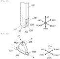
- the joint part 3 is formed by the first yoke part 31 provided in the approximately central part on the upper surface side of the top surface part 11 in the head part 1, a second yoke part 32 provided at a lower end part of the handle part 2 and a connecting part 33 connecting the first yoke part 32 and the second yoke part 33 as shown in Fig. 1 , Fig. 2 and Fig. 3 .
- the first yoke part 31 is formed by two symmetrical first protruding parts 311 facing at first facing surface parts 3111, which are formed integrally with the top surface part 11 at the central part on the upper surface side of the top surface 11 in the head part 1 as shown in Fig. 1 , Fig. 2 , Fig. 3 and Fig. 10 .
- a portion used for connecting to another member, which is formed with two symmetrical protrusions is called the "yoke part".
- the first protruding parts 311 are formed so as to be gradually increased in height toward the first facing surface parts 3111 where the first protruding parts 311 face each other when seen from the X-axis direction and are arranged side by side in the Y-axis direction as shown in Fig. 1 , Fig. 2 , Fig. 3 and Fig. 10 .
- the first protruding parts 311 are each formed to have 5mm to 20mm, more preferably, 8mm to 15mm in the X-axis direction and to have 10mm to 50mm, more preferably, 15mm to 30mm in the Y-axis direction.
- the first protruding parts 311 are formed to have 5mm to 15mm, more preferably, 8mm to 12mm in the Z-axis direction so as to be the same height or higher than the raised parts 111 at portions close to the first facing surface parts 3111 at the highest part.
- the first protruding parts 311 are arranged so that the first facing surface parts 3111 have a clearance of 10mm to 25mm, more preferably, 15mm to 20mm therebetween.
- the first facing surface parts 3111 are surfaces where the first protruding parts 311 face each other as shown in Fig. 1 , Fig. 2 and Fig. 10 , which are formed to have an approximately rectangular shape standing almost vertically from the upper surface side of the top surface part 11 so that the first facing surface parts 311 are parallel to each other.
- hole parts 3113 are formed in the first facing surface parts 3111 as shown in Fig. 10 .
- the hole parts 3113 are cylindrical holes formed in the first facing surface parts 3111, which are used for connecting to a first rotating axial center part 331 of the connecting part 33, which is described later.
- Side surface parts 3112 are surfaces facing the X-axis direction in parallel to a YZ plane in the first protruding parts 311 and formed continuously from front and back both sides of the first facing surface parts 3111, which are formed so as to stand almost vertically from the upper surface side of the top surface part 11 in the head part 1.
- the second yoke part 32 is formed by two symmetrical second protruding parts 321 extending in the axial direction at a lower end part of the handle body 21 in the handle part 2 and a second axial member 322 stretched over between second facing surface parts 3211 of the second protruding parts 321 as shown in Fig. 1 , Fig. 2 , Fig. 3 and Fig. 11 .
- the second protruding parts 321 are integrally formed with the handle body 21 so that the second facing surface parts 3211 face each other in parallel at both end parts in the X-axis direction in the state shown in Fig. 1 at the lower end of the handle body 21 as shown in Fig. 1 , Fig. 3 and Fig. 11 .
- the second protruding parts 321 each have a thickness of 2mm to 6mm, more preferably, 3mm to 5mm in the X-axis direction and a width approximately the same as that of the handle body 21 in the Y-axis direction in the state shown in Fig. 1 .
- the thickness in the X-axis direction is too thin, strength is insufficient when being pressed at the time of cleaning, which leads to breakage easily.
- the handle interferes with an upper surface of the head part when the handle is laid in the X-direction, and it is difficult to lean the handle to an approximately parallel state.
- the second facing surface parts 3211 are arranged so as to have a clearance of 2mm to 10mm, more preferably, 3mm to 7mm therebetween.
- the second axial member 322 is formed integrally with the second protruding parts 321 so as to be stretched along the X-axis direction in the central part in the Y-axis direction between the second facing surface parts 3211 as shown in Fig. 11 .
- the connecting part 33 is provided in a manner of being interposed between the first yoke part 31 and the second yoke part 32 as shown in Fig. 1 , Fig. 2 and Fig. 3 , which is formed in an approximately triangular shape when seen from the X-axis direction and includes the first rotating axial center part 331 and a second rotating axial center part 332 central axes of which are orthogonal to each other without crossing each other in a manner of crossing three-dimensionally as shown in Fig. 12 .
- connecting part 33 As a material for forming the connecting part 33, for example, polyacetate is used.
- the first rotating axial center part 331 is a portion used for connecting to the first yoke part 31 formed in the lower end part of the connecting part 33, including columnar protruding parts 3311 at both end parts in the Y-axis direction.
- the first rotating axial center part 331 is formed so that a width of a portion other than the protruding parts 3311 in the Y-axis direction is approximately the same as the clearance between the first facing surface parts 3111 of the first protruding parts 311 as well as the protruding parts 3311 have the approximately the same shape as the hole parts 3113. Therefore, the connecting part 33 can be attached to the first yoke part 31 so as to rotate about the Y-axis direction by fitting the protruding parts 3311 to the hole parts 3113.
- a central axis of the first rotating axial center part 331 shown in Fig. 12 along the Y-axis direction is set as a first axial center "a".
- the second rotating axial center part 332 is a portion used for connecting to the second yoke part 32 formed in an upper end part of the connecting part 33 as shown in Fig. 12 , having a second mounting hole part 3321 having an approximately cylindrical shape piercing in the front and back direction with part in the upper end part being cut out.
- a diameter of a cylindrical space formed inside the second mounting hole part 3321 is approximately the same as a diameter of the second axial member 322.
- a length in the X-axis direction is formed to be approximately the same as a length of the second axial member 322, and the connecting part 33 can be fixed to the second yoke part 32 so as to rotate about the X-axis direction by fitting the second axial member 322 to the second mounting hole part 3321.
- a central axis of the second rotating axial center part 332 shown in Fig. 12 along the X-axis direction is set as a second axial center "b".
- weights of the head part 1 and the handle part 2 are adjusted so that the center of gravity is positioned in a part close to the head part 1 (Q1 in Fig. 13 ) when the handle part 2 is divided into two in the longitudinal direction in a state where the handle part 2 is horizontally laid down as shown in Fig. 13 both in a state where the bottom surface part 12 is attached to the head part 1 and a state where the bottom surface part 12 is not attached to the head part 1.
- the above center of gravity can be realized by setting, for example, a mass of the top surface part 11 to 114.5g, a mass of the bottom surface part 12 to 65.7g and the entire mass of the handle part 2 to 197.8g.
- the head part 1 can be increased in weight by attaching the bottom surface part 12 to the head part 1 when cleaning low places such as the floor surface. Accordingly, the force necessary for the user to press the floor surface is reduced and cleaning of low places such as the floor surface can be performed easily.
- the head part 1 can be reduced in weight by removing the bottom surface part 12 from the head part 1. Accordingly, the burden of the user at the time of cleaning high places can be reduced.
- weights of the head part 1 and the handle part 2 are adjusted in the cleaning tool 100 so that the center of gravity is positioned at the part close to the head part 1 (Q1 in Fig. 13 ) when the handle part 2 is divided into two in the longitudinal direction in the state where the handle part 2 is horizontally laid down both in the state where the bottom surface part 12 is attached to the head part 1 and the state where the bottom surface part 12 is not attached to the head part 1. Accordingly, cleaning can be performed stably in both states.
- the center of gravity position is positioned in the above position in both cases where low places such as the floor surface are cleaned by attaching the bottom surface part 12 and where high places such as the ceiling and the upper part of the wall are cleaned by removing the bottom surface part 12, therefore, cleaning can be performed easily.
- the mass of the bottom surface part 12 is set in a suitable range, specifically, in a range of 30g to 600g, more preferably, 50g to 500g, thereby further facilitating the cleaning of low places such as floor surface.
- the bottom surface part 12 can be removed from the top surface part 11, therefore, the bottom surface part 12 can be washed alone. Accordingly, the bottom surface part 12 easily getting dirty at the time of cleaning can be washed by removing the bottom surface part 12 alone, therefore, maintenance of the cleaning tool can be performed easily.
- the center of gravity position may be changed by changing the length of the handle by allowing the handle part 2 to be divided into plural parts.
- the length of the handle part 2 can be changed to be 70 to 80%, 50 to 60% and 30 to 40% with respect to the longest case.
- the entire length of the handle part 2 is allowed to be changed in four stages of 1100mm, 860mm, 615mm and 375mm. Accordingly, the length of the handle part 2 can be changed to lengths of 78%, 56% and 34% with respect to the longest case of 1100mm.
- a means for changing the length of the handle part 2 is not limited to the method of dividing the handle part 2 into plural parts.
- the length can be changed by forming the handle part 2 so as to freely extend and contract.
- the center of gravity position may be changed by changing a weight ratio between the head part 1 and the handle part 2 by allowing the handle part 2 to be divided into plural parts.
- the weight of the head part 1 can be changed to be 85 to 95%, 110 to 120%, 150 to 160% and 230 to 250% with respect to the weight of the handle part 2.
- the mass of the head part 1 is 180g
- the mass of the handle part 2 is allowed to be changed in four stages of 197.8g. 157.3g, 116.6g and 76.1g.
- the weight of the head part 1 can be changed to be 91%, 114%, 154% and 236% with respect to the weight of the handle part 2.
- a means for changing the weight of the handle part 2 is not limited to the method of dividing the handle part 2 into plural parts.
- the weight can be changed by attaching a given weight to the handle part 2 and attaching/detaching the weight.
- the top surface part 11 was formed in a rectangular shape in plan view with a long side of 240mm and a short side of 95mm by using ABS resin
- the bottom surface part 12 was formed in a rectangular shape in plan view with a long side of 248mm and a short side of 98mm by using elastomer (TPE) having a hardness of 70 degrees.
- TPE elastomer
- the top surface part 11 and the bottom surface part 12 are formed to be freely attachable/detachable.
- the head part 1 was formed so that a mass of the top surface part 11 is 114.5g and a mass of the bottom surface part 12 is 20g.
- the handle part 2 was formed so that a length from the connection part with respect to the head part 1 to the upper end of the grip part 22 is 1120mm and a mass is 197.8g.
- the handle body 21 can be divided into plural parts as shown Fig. 13 , and masses of respective parts were measured in a state where the lowest portion of the handle part 2 is connected to the head part 1. Therefore, the mass of the top surface part 11 includes a mass of the lowest end portion of the handle body 21, and the mass of the handle part 2 does not include the mass of that portion.
- the lower surface of the bottom surface part 12 in the above cleaning tool was formed as follows.
- the linear ribs 124 were formed so that the oblique-line ribs 1241 had a curved shape with a length of 10mm to 80mm and the rhombus-shaped ribs 1242 had a size of 50mm in the X-axis direction and 28mm in the Y-axis direction as a larger one and a size of 14mm in the X-axis direction and 11mm in the Y-axis direction as a smaller one by linear ribs with 0.3mm in the lower direction and a width of 1mm.
- the oblique-line ribs 1241 were arranged at intervals of 6mm at the narrowest part and 9mm at the widest part.
- Four rhombus-shaped ribs 1242 were arranged at positions 10mm in oblique directions from four corners, one in the center and two in middle positions between the center and end parts.
- the end-part ribs 125 were formed so that a height from the flat surface part on the lower surface of the bottom surface part was 2mm in the lower direction, a length in the Y-axis direction was 23mm and a width in the X-axis direction was 1mm, and the end-art protrusions 126 were formed so that a height from the flat surface part on the lower surface of the bottom part was 2mm in the lower direction and 1.5mm in the Y-axis direction.
- the cleaning sheet P As the cleaning sheet P, a dry sheet formed in a rectangular shape with a long side of 300mm and a short side of 200mm, having a 100gsn in weighing, to which emboss processing was performed was used. Specifically, the cleaning sheet P was formed to have convex embosses EM1 and concave embosses EM2 as shown in Fig. 14 , so that each emboss had 8mm in a long-side direction, 3mm in a short-side direction and 0.8mm in height. A direction in which the emboss is elongated in plan view, namely, the X-axis direction in Fig. 14 is the long-side direction, and a direction in which the emboss is short in plan view, namely, the Y-axis direction in Fig. 14 is the short-side direction.
- non-woven fabric mainly composed of polyethylene-telephralate was used as a hydrophilic fiber for an outer layer of the cleaning sheet
- a fiber mainly composed of polypropylene was used as a hydrophilic fiber for an inner layer of the cleaning sheet.
- the outer layer is composed of 100% hydrophilic fiber, in which 80% polyethylene-telephralate is contained as the hydrophilic fiber and 20% core-sheath fiber of polypropylene and polyethylene as a binder fiber.
- the polyethylene-telephralate fiber with a fineness of 3.3dtex and the binder fiber with a fineness of 1.7dtex were used.
- the inner layer is formed of spun bond non-woven fabric of 100% polypropylene.
- Spun lace non-woven fabric of a three-layer structure including the inner layer and the outer layer is formed by water-flow interlacing.
- the bottom surface part 12 was formed to have a mass of 30g.
- Other structures are the same as those of Example 1.
- the bottom surface part 12 was formed to have a mass of 50g.
- Other structures are the same as those of Example 1.
- the bottom surface part 12 was formed to have a mass of 65.7g.
- Other structures are the same as those of Example 1.
- the bottom surface part 12 was formed to have a mass of 200g.
- Other structures are the same as those of Example 1.
- the bottom surface part 12 was formed to have a mass of 500g.
- Other structures are the same as those of Example 1.
- the bottom surface part 12 was formed to have a mass of 600g.
- Other structures are the same as those of Example 1.
- the bottom surface part 12 was formed to have a mass of 700g.
- Other structures are the same as those of Example 1.
- the bottom surface part 12 was not allowed to be removed from the top surface part 11 and to have a mass of 200g.
- Other structures are the same as those of Example 1.
- the bottom surface part 12 was not allowed to be removed from the top surface part 11 and to have a mass of 30g.
- Other structures are the same as those of Example 1.
- the bottom surface part 12 was not allowed to be removed from the top surface part 11 and to have a mass of 50g.
- Other structures are the same as those of Example 1.
- the bottom surface part 12 was not allowed to be removed from the top surface part 11 and to have a mass of 65.7g.
- Other structures are the same as those of Example 1.
- the bottom surface part 12 was not allowed to be removed from the top surface part 11 and to have a mass of 200g.
- Other structures are the same as those of Example 1.
- the bottom surface part 12 was not allowed to be removed from the top surface part 11 and to have a mass of 500g.
- Other structures are the same as those of Example 1.
- the bottom surface part 12 was not allowed to be removed from the top surface part 11 and to have a mass of 600g.
- Other structures are the same as those of Example 1.
- the bottom surface part 12 was not allowed to be removed from the top surface part 11 and to have a mass of 700g.
- Other structures are the same as those of Example 1.
- the head part 1 is formed not to have the bottom surface part 12. Other structures are the same as those of Example 1.
- the floor surface, the ceiling and the upper part of the wall were cleaned by a subject by using the cleaning tools of the above examples and comparative examples, and sensory evaluation concerning easiness in cleaning was performed.
- cleaning tools to/from which the bottom surface part 12 can be freely attached/detached cleaning was performed by attaching the bottom surface part 12 at the time of cleaning the floor surface, and cleaning was performed without attaching the bottom surface part 12 at the time of cleaning the ceiling and the upper part of the wall.
- the present invention can be suitably utilized in a manufacturing field of the cleaning tool.
Landscapes
- Cleaning Implements For Floors, Carpets, Furniture, Walls, And The Like (AREA)
Abstract
Description
- The present invention relates to a cleaning tool.
- There has been known in the past a cleaning tool for cleaning a floor surface including a head part to which a member for cleaning such as a cleaning sheet is attached, a handle part for gripping the cleaning tool by a user and a joint part for connecting the head part to the handle part, in which the head part and the handle part are rotatably connected through the joint part.
- In such cleaning tool, the efficiency of cleaning depends on a shape of the head part to which the member for cleaning is attached, therefore, the shape of the head part is variously devised. For example, there exists a cleaning tool in which a gap of an approximately triangular shape in cross section is held at a peripheral fringe part of a cleaning head to allow a side part of the cleaning head to be easily deformed and to allow the peripheral fringe part of the cleaning head to easily fit to shapes of edge parts on the floor surface and the like at the time of cleating, thereby cleaning the edge parts on the floor surface and the like efficiently (for example, refer to Patent Literature 1).
- Patent Literature 1:
JP-A-2013-34766 - However, even when the shape of the head part is devised as in the cleaning tool described in the above Patent Literature, a burden of the user is increased and efficiency of cleaning is not improved if a weight of the cleaning tool is not appropriate in accordance with a place to be cleaned. Specifically, when low places such as the floor surface are cleaned, cleaning can be easily performed by using a head part having a certain degree of weight because a center of gravity in the cleaning tool is lowered and a force required to be applied by the user for pressing the floor surface and the like is reduced. On the other hand, when high places such as a ceiling and an upper part of a wall are cleaned, it is preferable that the head part has a light weight in many cases.
- An object of the present invention is to provide a cleaning tool capable of easily cleaning both low places such as the floor surface and high places such as the ceiling and the upper part of the wall.
- In order to solve the above problems, a cleaning tool according to a first aspect of the present invention includes a head part to which a member for cleaning is attached and a handle part connected to the head part and for being gripped by a user, in which the head part includes a top surface part forming an upper surface side, to which the handle part is connected and a bottom surface part forming a lower surface side, and the bottom surface part is formed to be freely attachable/detachable with respect to the top surface part.
- According to the first aspect of the present invention, it is possible to provide the cleaning tool capable of easily cleaning both low places such as the floor surface and high places such as the ceiling and the upper part of the wall.
- In the cleaning tool described in the second aspect of the present invention, a center of gravity may be positioned in a part close to the head part when the handle part is divided into two in a longitudinal direction in a state where the handle part is horizontally laid down both in a state where the bottom surface part is attached to the top surface part and a state where the bottom surface part is not attached to the top surface part in the cleaning tool according to the first aspect.
- According to the second aspect of the present invention, it is possible to provide the cleaning tool capable of performing cleaning stably both in the state where the bottom surface part is attached and the state where the bottom surface part is not attached.
- In the cleaning tool described in the third aspect of the present invention, the bottom surface part may be formed to have a mass of 30g to 600g in the cleaning tool according to the first aspect or the second aspect.
- According to the third aspect of the present invention, easiness in cleaning low places such as the floor surface can be further improved.
- In the cleaning tool described in the fourth aspect of the present invention, the handle part may be capable of adjusting a length, and a center of gravity position may be capable of being changed by changing the length of the handle part in the cleaning tool according to any one of first to third aspects.
- According to the fourth aspect of the present invention, it is possible to provide the cleaning tool capable of adjusting the center of gravity position by adjusting the handle part.
- In the cleaning tool described in the fifth aspect of the present invention, the handle part may be capable of adjusting a weight, and the center of gravity position may be capable of being changed by changing the weight of the handle part in the cleaning tool according to any one of first to fourth aspects.
- According to the fifth aspect of the present invention, it is possible to provide the cleaning tool capable of adjusting the center of gravity position by adjusting the handle part. Advantageous Effects of Invention
- According to the present invention, it is possible to provide the cleaning tool easily cleaning both low places such as the floor surface and high places such as the ceiling and the upper part of the wall.
-
- [
Fig. 1] Fig. 1 is a perspective view of a cleaning tool according to an embodiment. - [
Fig. 2] Fig. 2 is a front view of the cleaning tool according to the embodiment. An upper part of a handle part is omitted. - [
Fig. 3] Fig. 3 is a side view of the cleaning tool according to the embodiment. The upper part of the handle part is omitted. - [
Fig. 4A] Fig. 4A is a bottom view of a top surface part according to the embodiment. - [
Fig. 4B] Fig. 4B is a side view of the top surface part according to the embodiment. - [
Fig. 5] Fig. 5 is a view showing an example of a structure for allowing the top surface part and a bottom surface part to be freely attachable/detachable. - [
Fig. 6] Fig. 6 is a view showing an example of the structure for allowing the top surface part and the bottom surface part to be freely attachable/detachable. - [
Fig. 7] Fig. 7 is a bottom surface view of a head part. - [
Fig. 8A] Fig. 8A is a front view of a grip part according to the embodiment. - [
Fig. 8B] Fig. 8B is a side view of the grip part according to the embodiment. - [
Fig. 8C] Fig. 8C is a back view of the grip part according to the embodiment. - [
Fig. 8D] Fig. 8D is a plan view of the grip part according to the embodiment. - [
Fig. 9] Fig. 9 is a view showing a state where a user of the cleaning tool grips the grip part. - [
Fig. 10] Fig. 10 is a perspective view of a first yoke part in a joint part of the cleaning tool according to the embodiment. - [
Fig. 11] Fig. 11 is a perspective view of a lower part of the handle part and a second yoke part in the joint part of the cleaning tool according to the embodiment. - [
Fig. 12] Fig. 12 is a perspective view of a connecting part in the joint part of the cleaning tool according to the embodiment. - [
Fig. 13] Fig. 13 is a view showing a center of gravity position of the cleaning tool. - [
Fig. 14] Fig. 14 is a view showing part of a cleaning sheet used in examples and comparative examples. - Hereinafter, specific modes of a
cleaning tool 100 according to an embodiment of the present invention will be explained with reference toFig. 1 to Fig. 13 . However, the technical scope of the present invention is not limited to the shown examples. - Explanation will be made by defining X-axis, Y-axis and Z-axis directions as well as a front-and-back direction, a left-and-right direction and an up-and-down direction as shown in
Fig. 1 . - The
cleaning tool 100 includes ahead part 1 to which a cleaning sheet P is attached, ahandle part 2 for grapping thecleaning tool 100 by a user and ajoint part 3 connecting thehead part 1 to thehandle part 2. - The
head part 1 is formed by atop surface part 11 and abottom surface part 12 made of different materials, and thehandle part 2 is attached to an approximately central part on an upper surface of thetop surface part 11 through thejoint part 3 as shown inFig. 1 ,Fig. 2 and Fig. 3 . - The
top surface part 11 is an approximately rectangular member in plan view being elongated in the Y-axis direction with a size of 50mm to 150mm, preferably 70mm to 120mm in the X-axis direction, and 200mm to 300mm, preferably 220mm to 270mm in the Y-axis direction, which is formed of a hard material such as ABS resin (acrylonitrile, butadiene, styrene copolymer synthetic resin). - An upper surface side of the
top surface part 11 is formed so that portions close to both end parts in the Y-axis direction are higher and portions close to the central part in the Y-axis direction are lower. Raisedparts 111 are formed closed to the both end parts in the Y-axis direction and a sunkpart 112 is formed close to the central part in the Y-axis direction. - A lower surface side of the
top surface part 11 is connected to an upper surface side of thebottom surface part 12. - The
top surface part 11 is formed to have a mass of 50g to 400g, more preferably, 80g to 300g. - The raised
parts 111 are formed to be raised upward close to the both end parts in the Y-axis direction on the upper surface side of thetop surface part 11 in front view as shown inFig. 2 . The raisedpart 111 is formed so as to gradually raised from the front-and-back direction toward a central part in the X-axis direction so that portions close to the central part in the X-axis direction are highest as shown inFig. 3 . - The raised
part 111 is formed so that a thickness of thehead part 1 is 10mm to 30mm, preferably 15mm to 25mm in the highest portion. When the thickness of thehead part 1 is lower than 10mm, it is difficult to insert a finger at the time of attaching the sheet to later-describedattachment parts 13 and the sheet comes off easily. When the thickness of thehead part 1 is higher than 30mm, entering to places under furniture with low legs such as under a couch or a rack becomes difficult. - Specific arrangement positions and shapes of the raised
parts 111 are not limited to the above can be suitably altered in a condition that the raisedparts 111 can be lifted when thehandle part 2 climbs over first protrudingparts 311. - It is preferable that the raised
parts 111 are formed close to the both end parts in a longitudinal direction of thehead part 1 in plan view, however, the present invention is not limited to this, and the raisedparts 111 are preferably formed close to both end parts in the same direction as a direction in which two first protrudingparts 311 of a later-describedfirst yoke part 31 are aligned. - The sunk
part 112 is formed so as to gradually sink from the raisedparts 111 formed at both end parts in a part close to the central part in the Y-axis direction on the upper surface side of thetop surface part 11 as shown inFig. 2 . - The sunk
part 112 is formed so that a thickness of thehead part 1 is 15mm or less, preferably 12mm or less in the central part of thetop surface part 11 to which thehandle part 2 is attached through thejoint part 3. -
Ribs 113 protruding downward are formed on the lower surface of thetop surface part 11 as shown inFigs. 4A and 4B . In theribs 113,high ribs 1131 which are largely convex downward are formed close to the central part of thetop surface part 11 in plan view andlow ribs 1132 which are convex downward in a lower degree than thehigh ribs 1131 are formed at other parts as shown inFig. 4A . Thehigh ribs 1131 are formed so as to be the same height at all places and thelow ribs 1132 are formed so as to be gradually reduced in height from thehigh ribs 1131 toward fringe part directions on thetop surface part 11 as shown inFig. 4B . - The
high ribs 1131 are formed so as to protrude downward by 0.5mm to 5mm, more preferably, 1mm to 3mm from a lower end portion of a fringe part of thetop surface part 11 shown inFig. 4B . - The
high ribs 1131 are formed in a range of 10% to 90%, more preferably, 50% to 80% with respect to the whole length in the longitudinal direction of thetop surface part 11. Thehigh ribs 1131 are formed in a range of 10% to 75%, more preferably, 30% to 60% with respect to the whole length in a short-side direction of thetop surface part 11. - Accordingly, a portion close to the center of the
bottom surface part 12 in plan view is strongly pushed by the lower surface of thetop surface part 11, and it is possible to collect dust effectively at the portion close to the center of thebottom surface part 12 in plan view. Also in this case, portions close to end parts of thebottom surface part 12 are not pushed strongly, therefore, it is preferable for introducing dust to a lower surface side of thebottom surface part 12. - The
bottom surface part 12 is formed of a softer material than that of thetop surface part 11, which can be elastically deformed such as TPE (thermoplastic elastomer) so as to have a rectangular shape approximately congruent with thetop surface part 11 in plan view as shown inFig. 1 ,Fig. 2 and Fig. 3 . Thebottom surface part 12 is formed to have a thickness of 1mm to 10mm, more preferably, 3mm to 4mm in the Z-axis direction. Thebottom surface part 12 may be formed slightly larger than thetop surface part 11. - A rubber hardness of the material to be used is preferably 60 to 100 (a value measured by a durometer type A (Shore A) standardized by JIS K 6253) from a viewpoint of a dust collection property.
- The
bottom surface part 12 is formed so that the upper surface side is approximately parallel to the lower surface side, and is connected to thetop surface part 11 on the upper surface side. - The
bottom surface part 12 is formed to have a mass of 30g to 600g, more preferably, 50g to 500g. When the mass of thebottom surface part 11 is too small, it is necessary for the user to apply a strong force for pressing a floor surface or the like at the time of cleaning low places such as the floor surface with thebottom surface part 12 attached. When the mass of thebottom surface part 11 is too large, thecleaning tool 1 becomes too heavy and the burden of the user is increased, therefore, both cases are not desirable. - The
bottom surface part 12 is formed to be freely attachable/detachable with respect to thetop surface part 11. Thebottom surface part 12 and thetop surface part 11 can be freely attached/detached to/from each other by an arbitrary method such that a concave part is provided on the upper surface side of thebottom surface part 12 and a convex part is provided on the lower surface side of thetop surface part 11 so that these parts can be fitted to each other. - Specifically, for example, the
bottom surface part 12 can be freely attachable/detachable with respect to thetop surface part 11 when adopting the following structure. - First, the
bottom surface part 12 is formed to be slightly larger than thetop surface part 11 in plan view as shown inFig. 5 . Specifically, thebottom surface 12 is formed to be larger than thetop surface part 11 in plan view by approximately 0.5mm to 5mm, more preferably, 1mm to 3mm in the X-axis direction, 0.5mm to 10mm, more preferably, 1mm to 5mm in the Y-axis direction and 0.5mm t0 20mm, more preferably, 5mm to 15mm at four corners. - Moreover, a fringe
convex part 12a is formed close to a fringe part in plan view in thebottom surface part 12 so as to extend around a fringe on the upper surface side of thebottom surface 12, and aconcave part 12b is formed on an inner peripheral side thereof as shown inFig. 6 . Theconcave part 12b is formed so as to be approximately congruent with thetop surface part 11. - Furthermore, a
rib 12c is formed on a slightly inner side of the fringeconvex part 12a in theconcave part 12b as shown inFig. 6 , and the fringe of thetop surface part 11 is fitted between the fringeconvex part 12a and therib 12c, thereby allowing both parts to be freely attached/detached to/from each other. - A level difference between the fringe
convex part 12a and theconcave part 12b is 0.5mm to 5mm, more preferably, 1mm to 3mm. - It is not always necessary that the
rib 12c is formed over the entire periphery as shown inFig. 6 but may be formed at only part thereof. For example, only ribs formed at portions surrounded in a shape of a semicircle or the like as shown inFig. 6 may be formed, and thetop surface part 11 may be fixed by portions only between these ribs and the fringeconvex part 12a. - On the lower surface side of the
bottom surface part 12, aflat surface part 121, short-side direction recessedparts 122 and longitudinal-direction recessedparts 123 are formed. - The
flat surface part 121 is a portion formed in an approximately flat surface shape except for later-describedlinear ribs 124, which is the portion other than the short-side direction recessedparts 122 and the longitudinal-direction recessedparts 123 on the lower surface side of thebottom surface part 12 as shown inFig. 7 . - The
bottom surface part 12 corresponds to the entire member formed by an elastically deformable material forming the lower side of thehead part 1, and theflat surface part 121 corresponds to a portion formed in the approximately flat surface shape in the lower surface of thebottom surface part 12. - The short-side direction recessed
parts 122 are portions formed to be recessed upward at positions close to both end parts in the short-side direction (X-axis direction) on the lower surface side of thebottom surface part 12 as shown inFig. 2 andFig. 7 . According to the parts, portions close to both end parts in the short-side direction (X-axis direction) on the lower surface side of thehead part 1 do not closely contact the floor surface, and gaps are generated between thehead part 1 and the floor surface at the time of using thecleaning tool 100. - The short-side direction recessed
parts 122 can be formed in an arbitrary shape as far as gaps can be generated with respect to the floor surface on the lower surface side close to the both end parts in the short-side direction (X-axis direction) of thehead part 1, however, it is preferable that the short-side direction recessedpart 122 is formed so that the lower surface side of thebottom surface part 12 is recessed to the largest degree in a central part in the Y-axis direction of an end part on the front side or the back side of thehead part 1 and the recess is reduced as going away from that part to be connected to theflat surface part 121 smoothly. - The short-side direction recessed
part 122 is formed to be recessed upward by 0.1mm to 5mm, more preferably, 0.5mm to 3mm as compared with theflat surface part 121 at the most recessed part. - As the short-side direction recessed
parts 122 are formed on the lower surface side of thebottom surface part 12, dust on the floor surface is introduced to the lower surface of thehead part 1 without being gathered at end parts on front and back of thehead part 1 at the time of cleaning the floor surface by moving thecleaning tool 100 in the short-side direction (X-axis direction) of thehead part 1, as a result, the dust collection property can be improved. - The longitudinal-direction recessed
parts 123 are portions formed to be recessed upward at positions close to both end parts in the longitudinal direction (Y-axis direction) on the lower surface side of thebottom surface part 12 as shown inFig. 3 andFig. 7 . According to the parts, portions close to both end parts in the longitudinal direction (Y-axis direction) on the lower surface side of thehead part 1 do not closely contact the floor surface, and gaps are generated between thehead part 1 and the floor surface at the time of using thecleaning tool 100. - The longitudinal direction recessed
parts 123 can be formed in an arbitrary shape as far as gaps can be generated with respect to the floor surface on the lower surface side close to the both end parts in the longitudinal direction (Y-axis direction) of thehead part 1, however, it is preferable that the longitudinal direction recessedpart 123 is formed so that the lower surface side of thebottom surface part 12 is recessed to the largest degree in a central part in the X-axis direction of an end part on the right side or the left side of thehead part 1 and the recess is reduced as going away from that part to be connected to theflat surface part 121 smoothly. - The longitudinal direction recessed
part 123 is formed to be recessed upward by 0.1mm to 5mm, more preferably, 0.5mm to 3mm as compared with theflat surface part 121 at the most recessed part. - As the longitudinal direction recessed
parts 123 are formed on the lower surface side of thebottom surface part 12, dust on the floor surface is introduced to the lower surface of thehead part 1 without being gathered at end parts on left and right of thehead part 1 at the time of cleaning the floor surface by moving thecleaning tool 100 in the longitudinal direction (Y-axis direction) of thehead part 1, as a result, the dust collection property can be improved. - On the
flat surface part 121 on the lower surface side of thebottom surface part 12, thelinear ribs 124 which are convex downward are formed so as to be a linear shape in bottom view as shown inFig. 7 . - All the
linear ribs 124 are formed so as to have the same height in the Z-axis direction, specifically, formed to protrude downward by 0.1mm to 2mm, more preferably, 0.2mm to 1mm. Each linear rib is formed in a liner shape with a length of 1mm to 100mm, more preferably, 8mm to 85mm, and with a width of 0.1mm to 2mm, more preferably, 0.2mm to 1.2mm. - The
liner ribs 124 include both ribs formed in the linear shape in bottom view and ribs formed in a curved shape in bottom view. - The
linear ribs 124 includes oblique-line ribs 1241 and rhombus-shapedribs 1242, and specific arrangement is as follows. - The oblique-
line ribs 1241 are portions other than the rhombus-shapedribs 1242 in thelinear ribs 124, which are formed on the almost entire surface of theflat surface part 121 other than portions where the rhombus-shapedribs 1242 are formed. - The oblique-
line ribs 1241 are formed in linear shapes inclined toward the center in the Y-axis direction from a direction parallel to the X-axis as coming toward the front direction or the back direction from the central part in the X-axis direction on the bottom surface of thehead part 1 in bottom view of thehead part 1 as shown inFig. 7 . - The rhombus-shaped
ribs 1242 are portions where the linear ribs are arranged in an approximately rhombus shape in bottom view as shown inFig. 7 , which are formed at a central part in the X-axis direction and the Y-axis direction, two places at midpoints between the central part and end parts in the Y-axis direction and four places near four corners on the lower surface of thehead part 1 in theflat surface part 121. - End-
part ribs 125 formed in a linear shape along the Y-axis direction are formed in the central part in the X-axis direction on the lower surface side close to the both end parts in the longitudinal direction (Y-axis direction) on the lower surface side of thebottom surface part 12. - The end-
part ribs 125 are formed to have a height of 1mm to 5mm in a lower direction seen from theflat surface part 121. When the height is lower than 1mm, it is difficult to clean a groove sufficiently, and when the height is higher than 5mm, a possibility of being an obstruction at the time of cleaning a flat surface on the floor surface is increased. However, it is necessary that the end-part ribs 125 are formed to be higher than thelinear ribs 124 in the Z-axis direction. - It is necessary that the end-
part ribs 125 are formed to have the above height with respect to theflat surface part 121 also in the case where the end-part ribs 125 are formed so as to overlap with the longitudinal direction recessedparts 123 as shown inFig. 7 . - Moreover, the end-
part ribs 125 are formed so that a length in the Y-axis direction is 10mm to 50mm, more preferably, 20mm to 30mm and a width in the X-axis direction is 0.1mm to 3mm, more preferably, 0.5mm to 1.5mm. - As the end-
part ribs 125 are provided, not only the flat surface on the floor surface but also the groove can be cleaned by allowing the ribs to enter the groove on the floor surface. - In central parts in the X-axis direction in both end parts in the longitudinal direction (Y-axis direction) of the
head part 1, end-part protrusions 126 protruding in the Y-axis direction so as to be continued from the end-part ribs 125 are formed as shown inFig. 1 ,Fig. 2 andFig. 7 . The end-part protrusions 126 are formed to protrude to the right direction and the left direction from both end parts in the longitudinal direction (Y-axis direction) of thehead part 1 by 0.5mm to 3mm, more preferably, 0.8mm to 2mm. -
Hole parts 127 which are convex upward as shown inFig. 7 are formed close to the both end parts in the longitudinal direction on the lower surface side of thebottom surface part 12. According to the holes, portions close to the both end parts in the longitudinal direction of thebottom surface part 12 becomes flexible, and thebottom surface part 12 can be attached/detached to/from thetop surface part 11 easily. - Respective holes forming the
hole parts 127 are formed so that the size thereof becomes largest at portions close to four corners of thebottom surface part 12 and reduced as coming close to the end-part ribs 125 in bottom view. Specifically, the holes are formed to have lengths of 3mm to 15mm, more preferably, 5mm to 10mm as larger sizes and lengths of 1mm to 5mm, more preferably, 2mm to 4mm as smaller sizes both in the X-axis direction and the Y-axis direction in bottom view. - The
attachment parts 13 are provided close to four corners on the upper surface of thetop surface part 11 in plan view as shown inFig. 1 . Theattachment parts 13 are holes withclaw parts 131 formed of EVA (ethylene-vinyl acetate copolymer) or the like around the holes, which are formed on the raisedparts 111 on the upper surface of thetop surface part 11. The cleaning sheet P can be attached to thehead part 1 by pushing the cleaning sheet P to be caught by theclaw parts 131. Specifically, the cleaning sheet P is allowed to closely contact the lower surface side of thebottom surface part 12, and portions of the cleaning sheet P protruding from the lower surface side of thebottom surface part 12 are folded to the upper surface side of thetop surface part 11 and pushed into theattachment parts 13 provided on the upper surface side of thetop surface part 11, thereby attaching the cleaning sheet P to thehead part 1. - The shape of the
attachment parts 13 is not limited to the above shape as far as the cleaning sheet P can be attached to thehead part 1. - The
handle part 2 is a bar-shaped member used for being gripped by the user at the time of using thecleaning tool 100, including ahandle body 21 and agrip part 22 as shown inFig. 1 . Thehandle part 2 is rotatably connected to thehead part 1 through thejoint part 3. Explanation will be made by designating the front-and-back direction, the left and right direction and the up-and-down direction in a state where thehandle part 2 stands on thehead part 1 vertically as shown inFig. 1 . - The
handle body 21 is a bar-shaped member formed of a hard material such as ABS resin (acrylonitrile, butadiene, styrene copolymer synthetic resin), metal (aluminum, steel, stainless steel), polycarbonate and polypropylene, which is connected to the approximately central part on the upper surface side of thetop surface part 11 in thehead part 1 through the joint 3 at a lower end, and connected to thegrip part 22 at an upper end part. - The
handle body 21 is formed so that a thickness in the front-and-back direction is reduced as compared with a thickness in the left and right direction at a portion close to the lower end part as shown inFig. 3 . Accordingly, it becomes easy to lay thehandle part 2 in a lower state. - It is also preferable that the portion close to the lower end part of the
handle body 21 is formed to have the same thickness in the front/back direction and the right/left direction though the effect that thehandle part 2 can be easily laid in the lower state is reduced. The thickness in the front-and-back direction may be larger than the thickness in the left and right direction by giving weight to, for example, strength of later-described secondprotruding parts 321. - The
handle body 21 may be formed so as to be divided into plural portions as shown inFig. 13 . - The
handle body 21 is formed to have a length of 500mm to 1000mm, more preferably, 600mm to 900mm in the Z-axis direction. Thehandle body 21 is formed to have a mass of 50g to 300g, more preferably, 100g to 250g. - The
grip part 22 is a part gripped by the user at the time of using thecleaning tool 100 in thehandle part 2, which is connected to thehandle body 21 at a lower end part. - The
grip part 22 is formed to have a length of 100mm to 400mm, more preferably, 250mm to 350mm in the Z-axis direction, and to have an approximately circular shape with a diameter of 15mm to 45mm, more preferably, 20mm to 40mm at the thickest part in plan view. Thegrip part 22 is also formed to have a mass of 30g to 200g, more preferably, 50g to 100g. - The
grip part 22 may be formed as a separate member from thehandle body 21 as in the embodiment as well as may be integrally formed. - An upper surface of the
grip part 22 is formed to be inclined in one direction with respect to a surface (XY surface) perpendicular to the Z-axis to form aninclined surface 22a as shown inFig. 8B . Theinclined surface 22a is formed so as to be inclined by 30 degrees to 80 degrees, more preferably, 40 degrees to 70 degrees with respect to the XY surface. A point where theinclined surface 22a is the highest in the Z-axis direction, namely, a front end part of theinclined surface 22a is a tip end 22aa. - A
peripheral surface 22b of thegrip part 22, namely, a surface other than theinclined surface 22a on the upper surface and a lower surface connected to thehandle body 21 in outer surfaces of thegrip part 22 is formed to have a cross-sectional shape in which a diameter is gradually increased toward the upper part except for portions close to the lower end part and the upper end part where theinclined surface 22a is formed as shown inFig. 8A to Fig. 8B . - As shown in
Fig. 8C and Fig. 8D , agroove part 22c in which the handle body is concave in a groove shape in the X-axis direction is formed on a side in which theinclined surface 22a is lowered in the Z-axis direction, namely, the back side at an upper part of thegrip part 22. - The
groove part 22c is formed to have a depth of 0.5mm to 5mm, more preferably, 1mm to 3mm in the X-axis direction, to have a width of 5mm to 30mm, more preferably, 10mm to 20mm in the Y-axis direction and to have a length of 30mm to 100mm, more preferably, 40mm to 70mm in the Z-axis direction. - A
hole part 22d piercing from theinclined surface 22a to a tip end 22aa side, namely, the front side at the upper part of theperipheral surface 22b is formed at a portion close to the upper end part of thegrip part 22 as shown inFig. 8A to Fig. 8D . - The
hole part 22d includes a depressed part 22da in which theinclined surface 22a is depressed widely in a concave shape and a through hole 22db piercing from the depressed part 22da to the tip end 22aa side at the upper part of theperipheral surface 22b as shown inFig. 8C and Fig. 8D . - The
hole part 22d is formed so that the through hole 22db is a circular hole in plan view with a diameter of 5mm to 20mm, more preferably, 8mm to 15mm. - On the tip-end 22aa side, namely, the front side of the
peripheral surface 22b of thegrip part 22, anon-slip part 22e in which the surface of theperipheral surface 22b is raised at plural places in a horizontal linear shape is formed as shown inFig. 8A and Fig. 8B . - Plural linear protrusions forming the
non-slip part 22e are formed so that each protrusion has a height of 0.1mm to 2mm, more preferably, 0.5mm to 1mm in the X-axis direction, a length of 5mm to 50mm, more preferably, 10mm to 40mm in the Y-axis direction and a width of 1mm to 5mm, more preferably, 1.5mm to 3mm in the Z-axis direction. It is desirable that the linear protrusions forming thenon-slip part 22e are formed at intervals of 2mm to 10mm, more preferably, 3mm to 6mm in the Z-axis direction. - The
non-slip part 22e is formed at a position where a tip of a thumb contacts when the user of thecleaning tool 100 grips thegrip part 22 as shown inFig. 9 , specifically, at a position where a distance from the upper end part of thegrip part 22 is 30mm to 250mm, more preferably, 70mm to 180mm. - Though the case in which four linear protrusions are formed as the
non-slip part 22e is shown inFig. 8A and Fig. 8B , the structure of thenon-slip part 22e is not limited to this. Linear protrusions larger or smaller in number may be formed, and the non-slip part may be formed by protrusions other than linear protrusions such as punctiform protrusions. It is also preferable that thenon-slip part 22e is formed by sticking some material with a high frictional resistance on the surface. - Two protruding
parts 22f protruding toward the front direction are provided side by side in the Y-axis direction at portions close to the tip end 22aa of theperipheral surface 22b as shown inFig. 8A, Fig. 8B andFig. 8D . - Respective protruding
parts 22f are formed in a spherical shape with a side contacting theperipheral surface 22b being cut as shown inFig. 8A, Fig. 8B andFig. 8D so that a diameter of the sphere is 1mm to 10mm, more preferably, 2mm to 6mm. The protrudingparts 22f are formed to have a height from theperipheral surface 22b is 0.5mm to 5mm, more preferably, 1mm to 3mm. - The number of
protruding parts 22f is not always limited to two as far as plural points contact a wall when thehandle part 2 is leaned on the wall so that the tip end 22aa side faces the wall, and a larger number ofprotruding parts 22f may be provided. The shape is also not limited to the spherical shape. - A connecting
part 22g used for connecting to thehandle body 21 is provided at a lower part of thegrip part 22 as shown inFig. 8A to Fig. 8C , and thegrip part 22 is fitted to the upper part of thehandle body 21 to be freely attachable/detachable by using the connectingpart 22g. - An arbitrary structure may be adopted as the structure of the connecting
part 22g as far as two bar-shaped members can be connected so as to be freely detachable/attachable. - It is also preferable that the
grip part 22 does not have the connectingpart 22g and that thehandle body 21 is formed integrally with thegrip part 22. - A
soft part 221 is formed by a softer material as compared with a later-describedhard part 222 such as thermoplastic elastomers (styrene-based, olefin-based), urethane and EVA resin. Thesoft part 221 is preferably formed of a material with a rubber hardness 60 to 100 (a value measured by the durometer type A (Shore A) standardized by JIS K 6253) as a specific hardness. - The
soft part 221 is formed so as to cover around left and right of an upper part of theperipheral surface 22b of thegrip part 22 from the side where theinclined surface 22a is lowered, namely, the back side and so as not to cover the tip end 22aa side where theinclined surface 22a is increased in height, namely, the front side. - The
soft part 221 covers the approximately entireinclined surface 22a except for part of the front side where theinclined surface 22a is increased in height, and the entire inner surface of the depressed part 22da is also covered with thesoft part 221 as shown inFig. 8D . - The
soft part 221 is formed so as to cover the entire range in which fingers from a forefinger to a little finger reach when the user of the cleaning tool grips thegrip part 22 as shown inFig. 9 . Specifically, thesoft part 221 is preferably formed from an upper end of thegrip part 22 to a position approximately 40mm to 230mm, more preferably, 60mm to 160mm downward from the upper end. - The
hard part 222 is a part forming a body of thegrip part 22, which is the entire part of thegrip part 22 other than thesoft part 221. - The
hard part 222 is formed of a harder material as compared with thesoft part 221 such as plastic resin (polypropylene). - As the
soft part 221 is formed, thehard part 222 exists to an end part on the opposite side of a side connected to thehandle body 21 in theperipheral surface 22b on the front side of thegrip part 22, namely, to an upper end part as shown inFig. 8A and Fig. 8B . - The
joint part 3 is formed by thefirst yoke part 31 provided in the approximately central part on the upper surface side of thetop surface part 11 in thehead part 1, asecond yoke part 32 provided at a lower end part of thehandle part 2 and a connectingpart 33 connecting thefirst yoke part 32 and thesecond yoke part 33 as shown inFig. 1 ,Fig. 2 and Fig. 3 . - The
first yoke part 31 is formed by two symmetrical firstprotruding parts 311 facing at first facingsurface parts 3111, which are formed integrally with thetop surface part 11 at the central part on the upper surface side of thetop surface 11 in thehead part 1 as shown inFig. 1 ,Fig. 2 ,Fig. 3 andFig. 10 . In the embodiment, a portion used for connecting to another member, which is formed with two symmetrical protrusions is called the "yoke part". - The first protruding
parts 311 are formed so as to be gradually increased in height toward the first facingsurface parts 3111 where the first protrudingparts 311 face each other when seen from the X-axis direction and are arranged side by side in the Y-axis direction as shown inFig. 1 ,Fig. 2 ,Fig. 3 andFig. 10 . - The first protruding
parts 311 are each formed to have 5mm to 20mm, more preferably, 8mm to 15mm in the X-axis direction and to have 10mm to 50mm, more preferably, 15mm to 30mm in the Y-axis direction. The first protrudingparts 311 are formed to have 5mm to 15mm, more preferably, 8mm to 12mm in the Z-axis direction so as to be the same height or higher than the raisedparts 111 at portions close to the first facingsurface parts 3111 at the highest part. The first protrudingparts 311 are arranged so that the first facingsurface parts 3111 have a clearance of 10mm to 25mm, more preferably, 15mm to 20mm therebetween. - The first facing
surface parts 3111 are surfaces where the first protrudingparts 311 face each other as shown inFig. 1 ,Fig. 2 andFig. 10 , which are formed to have an approximately rectangular shape standing almost vertically from the upper surface side of thetop surface part 11 so that the first facingsurface parts 311 are parallel to each other. - Moreover,
hole parts 3113 are formed in the first facingsurface parts 3111 as shown inFig. 10 . - The
hole parts 3113 are cylindrical holes formed in the first facingsurface parts 3111, which are used for connecting to a first rotatingaxial center part 331 of the connectingpart 33, which is described later. -
Side surface parts 3112 are surfaces facing the X-axis direction in parallel to a YZ plane in the first protrudingparts 311 and formed continuously from front and back both sides of the first facingsurface parts 3111, which are formed so as to stand almost vertically from the upper surface side of thetop surface part 11 in thehead part 1. - The
second yoke part 32 is formed by two symmetrical secondprotruding parts 321 extending in the axial direction at a lower end part of thehandle body 21 in thehandle part 2 and a secondaxial member 322 stretched over between second facingsurface parts 3211 of the second protrudingparts 321 as shown inFig. 1 ,Fig. 2 ,Fig. 3 andFig. 11 . - The second
protruding parts 321 are integrally formed with thehandle body 21 so that the second facingsurface parts 3211 face each other in parallel at both end parts in the X-axis direction in the state shown inFig. 1 at the lower end of thehandle body 21 as shown inFig. 1 ,Fig. 3 andFig. 11 . - The second
protruding parts 321 each have a thickness of 2mm to 6mm, more preferably, 3mm to 5mm in the X-axis direction and a width approximately the same as that of thehandle body 21 in the Y-axis direction in the state shown inFig. 1 . When the thickness in the X-axis direction is too thin, strength is insufficient when being pressed at the time of cleaning, which leads to breakage easily. When the thickness is too thick, the handle interferes with an upper surface of the head part when the handle is laid in the X-direction, and it is difficult to lean the handle to an approximately parallel state. - The second facing
surface parts 3211 are arranged so as to have a clearance of 2mm to 10mm, more preferably, 3mm to 7mm therebetween. - The second
axial member 322 is formed integrally with the second protrudingparts 321 so as to be stretched along the X-axis direction in the central part in the Y-axis direction between the second facingsurface parts 3211 as shown inFig. 11 . - The connecting
part 33 is provided in a manner of being interposed between thefirst yoke part 31 and thesecond yoke part 32 as shown inFig. 1 ,Fig. 2 and Fig. 3 , which is formed in an approximately triangular shape when seen from the X-axis direction and includes the first rotatingaxial center part 331 and a second rotatingaxial center part 332 central axes of which are orthogonal to each other without crossing each other in a manner of crossing three-dimensionally as shown inFig. 12 . - As a material for forming the connecting
part 33, for example, polyacetate is used. - The first rotating
axial center part 331 is a portion used for connecting to thefirst yoke part 31 formed in the lower end part of the connectingpart 33, includingcolumnar protruding parts 3311 at both end parts in the Y-axis direction. - The first rotating
axial center part 331 is formed so that a width of a portion other than the protrudingparts 3311 in the Y-axis direction is approximately the same as the clearance between the first facingsurface parts 3111 of the first protrudingparts 311 as well as the protrudingparts 3311 have the approximately the same shape as thehole parts 3113. Therefore, the connectingpart 33 can be attached to thefirst yoke part 31 so as to rotate about the Y-axis direction by fitting the protrudingparts 3311 to thehole parts 3113. - A central axis of the first rotating
axial center part 331 shown inFig. 12 along the Y-axis direction is set as a first axial center "a". - The second rotating
axial center part 332 is a portion used for connecting to thesecond yoke part 32 formed in an upper end part of the connectingpart 33 as shown inFig. 12 , having a secondmounting hole part 3321 having an approximately cylindrical shape piercing in the front and back direction with part in the upper end part being cut out. A diameter of a cylindrical space formed inside the second mountinghole part 3321 is approximately the same as a diameter of the secondaxial member 322. A length in the X-axis direction is formed to be approximately the same as a length of the secondaxial member 322, and the connectingpart 33 can be fixed to thesecond yoke part 32 so as to rotate about the X-axis direction by fitting the secondaxial member 322 to the second mountinghole part 3321. - A central axis of the second rotating
axial center part 332 shown inFig. 12 along the X-axis direction is set as a second axial center "b". - In the
cleaning tool 100, weights of thehead part 1 and thehandle part 2 are adjusted so that the center of gravity is positioned in a part close to the head part 1 (Q1 inFig. 13 ) when thehandle part 2 is divided into two in the longitudinal direction in a state where thehandle part 2 is horizontally laid down as shown inFig. 13 both in a state where thebottom surface part 12 is attached to thehead part 1 and a state where thebottom surface part 12 is not attached to thehead part 1. - Specifically, the above center of gravity can be realized by setting, for example, a mass of the
top surface part 11 to 114.5g, a mass of thebottom surface part 12 to 65.7g and the entire mass of thehandle part 2 to 197.8g. - According to the embodiment, the
head part 1 can be increased in weight by attaching thebottom surface part 12 to thehead part 1 when cleaning low places such as the floor surface. Accordingly, the force necessary for the user to press the floor surface is reduced and cleaning of low places such as the floor surface can be performed easily. - At the time of cleaning high places such as the ceiling and the upper part of the wall, the
head part 1 can be reduced in weight by removing thebottom surface part 12 from thehead part 1. Accordingly, the burden of the user at the time of cleaning high places can be reduced. - According to the embodiment, weights of the
head part 1 and thehandle part 2 are adjusted in thecleaning tool 100 so that the center of gravity is positioned at the part close to the head part 1 (Q1 inFig. 13 ) when thehandle part 2 is divided into two in the longitudinal direction in the state where thehandle part 2 is horizontally laid down both in the state where thebottom surface part 12 is attached to thehead part 1 and the state where thebottom surface part 12 is not attached to thehead part 1. Accordingly, cleaning can be performed stably in both states. - That is, in both cases of cleaning low places such as the floor surface and cleaning high places such as the ceiling and the upper part of the wall, it becomes difficult to perform cleaning when the center of gravity of the cleaning tool is positioned too close to a user's hand as well as when it is positioned in the head part far from the user. Therefore, it is desirable that the center of gravity is positioned at the lower half part of the
handle part 2. - According to the embodiment, the center of gravity position is positioned in the above position in both cases where low places such as the floor surface are cleaned by attaching the
bottom surface part 12 and where high places such as the ceiling and the upper part of the wall are cleaned by removing thebottom surface part 12, therefore, cleaning can be performed easily. - Also according to the embodiment, the mass of the
bottom surface part 12 is set in a suitable range, specifically, in a range of 30g to 600g, more preferably, 50g to 500g, thereby further facilitating the cleaning of low places such as floor surface. - Further according to the embodiment, the
bottom surface part 12 can be removed from thetop surface part 11, therefore, thebottom surface part 12 can be washed alone. Accordingly, thebottom surface part 12 easily getting dirty at the time of cleaning can be washed by removing thebottom surface part 12 alone, therefore, maintenance of the cleaning tool can be performed easily. - The center of gravity position may be changed by changing the length of the handle by allowing the
handle part 2 to be divided into plural parts. - Specifically, it is desirable that the length of the
handle part 2 can be changed to be 70 to 80%, 50 to 60% and 30 to 40% with respect to the longest case. For example, the entire length of thehandle part 2 is allowed to be changed in four stages of 1100mm, 860mm, 615mm and 375mm. Accordingly, the length of thehandle part 2 can be changed to lengths of 78%, 56% and 34% with respect to the longest case of 1100mm. - A means for changing the length of the
handle part 2 is not limited to the method of dividing thehandle part 2 into plural parts. For example, the length can be changed by forming thehandle part 2 so as to freely extend and contract. - The center of gravity position may be changed by changing a weight ratio between the
head part 1 and thehandle part 2 by allowing thehandle part 2 to be divided into plural parts. - Specifically, it is desirable that the weight of the
head part 1 can be changed to be 85 to 95%, 110 to 120%, 150 to 160% and 230 to 250% with respect to the weight of thehandle part 2. For example, when the mass of thehead part 1 is 180g, the mass of thehandle part 2 is allowed to be changed in four stages of 197.8g. 157.3g, 116.6g and 76.1g. Accordingly, the weight of thehead part 1 can be changed to be 91%, 114%, 154% and 236% with respect to the weight of thehandle part 2. - A means for changing the weight of the
handle part 2 is not limited to the method of dividing thehandle part 2 into plural parts. For example, the weight can be changed by attaching a given weight to thehandle part 2 and attaching/detaching the weight. - Next, results obtained by evaluating easiness in cleaning low places such as the floor surface and high places such as the ceiling and the upper part of the wall using cleaning tools according to examples and comparative examples of the present invention will be explained. The present invention will be specifically explained by examples below, and the present invention is not limited to these examples.
- In the
head part 1, thetop surface part 11 was formed in a rectangular shape in plan view with a long side of 240mm and a short side of 95mm by using ABS resin, and thebottom surface part 12 was formed in a rectangular shape in plan view with a long side of 248mm and a short side of 98mm by using elastomer (TPE) having a hardness of 70 degrees. Thetop surface part 11 and thebottom surface part 12 are formed to be freely attachable/detachable. Thehead part 1 was formed so that a mass of thetop surface part 11 is 114.5g and a mass of thebottom surface part 12 is 20g. - The
handle part 2 was formed so that a length from the connection part with respect to thehead part 1 to the upper end of thegrip part 22 is 1120mm and a mass is 197.8g. - In the
handle part 2 according to the example, thehandle body 21 can be divided into plural parts as shownFig. 13 , and masses of respective parts were measured in a state where the lowest portion of thehandle part 2 is connected to thehead part 1. Therefore, the mass of thetop surface part 11 includes a mass of the lowest end portion of thehandle body 21, and the mass of thehandle part 2 does not include the mass of that portion. - The lower surface of the
bottom surface part 12 in the above cleaning tool was formed as follows. - The
linear ribs 124 were formed so that the oblique-line ribs 1241 had a curved shape with a length of 10mm to 80mm and the rhombus-shapedribs 1242 had a size of 50mm in the X-axis direction and 28mm in the Y-axis direction as a larger one and a size of 14mm in the X-axis direction and 11mm in the Y-axis direction as a smaller one by linear ribs with 0.3mm in the lower direction and a width of 1mm. - The oblique-
line ribs 1241 were arranged at intervals of 6mm at the narrowest part and 9mm at the widest part. Four rhombus-shapedribs 1242 were arranged at positions 10mm in oblique directions from four corners, one in the center and two in middle positions between the center and end parts. - The end-
part ribs 125 were formed so that a height from the flat surface part on the lower surface of the bottom surface part was 2mm in the lower direction, a length in the Y-axis direction was 23mm and a width in the X-axis direction was 1mm, and the end-art protrusions 126 were formed so that a height from the flat surface part on the lower surface of the bottom part was 2mm in the lower direction and 1.5mm in the Y-axis direction. - Thirty-six oblique-
line ribs 1241, seven rhombus-shapedribs 1242 including larger ones and smaller ones and two end-part ribs 125 including left and right ones were formed. - As the cleaning sheet P, a dry sheet formed in a rectangular shape with a long side of 300mm and a short side of 200mm, having a 100gsn in weighing, to which emboss processing was performed was used. Specifically, the cleaning sheet P was formed to have convex embosses EM1 and concave embosses EM2 as shown in
Fig. 14 , so that each emboss had 8mm in a long-side direction, 3mm in a short-side direction and 0.8mm in height. A direction in which the emboss is elongated in plan view, namely, the X-axis direction inFig. 14 is the long-side direction, and a direction in which the emboss is short in plan view, namely, the Y-axis direction inFig. 14 is the short-side direction. - Moreover, non-woven fabric mainly composed of polyethylene-telephralate was used as a hydrophilic fiber for an outer layer of the cleaning sheet, and a fiber mainly composed of polypropylene was used as a hydrophilic fiber for an inner layer of the cleaning sheet.
- Concerning details of the composition of the outer layer, a chemical fiber mainly composed of polyethylene-telephralate, polypropylene, polyethylene and the like is adopted. Specifically, the outer layer is composed of 100% hydrophilic fiber, in which 80% polyethylene-telephralate is contained as the hydrophilic fiber and 20% core-sheath fiber of polypropylene and polyethylene as a binder fiber. The polyethylene-telephralate fiber with a fineness of 3.3dtex and the binder fiber with a fineness of 1.7dtex were used.
- The inner layer is formed of spun bond non-woven fabric of 100% polypropylene.
- Spun lace non-woven fabric of a three-layer structure including the inner layer and the outer layer is formed by water-flow interlacing.
- Although the dry sheet was used in the embodiment, a wet sheet can be used.
- The
bottom surface part 12 was formed to have a mass of 30g. Other structures are the same as those of Example 1. - The
bottom surface part 12 was formed to have a mass of 50g. Other structures are the same as those of Example 1. - The
bottom surface part 12 was formed to have a mass of 65.7g. Other structures are the same as those of Example 1. - The
bottom surface part 12 was formed to have a mass of 200g. Other structures are the same as those of Example 1. - The
bottom surface part 12 was formed to have a mass of 500g. Other structures are the same as those of Example 1. - The
bottom surface part 12 was formed to have a mass of 600g. Other structures are the same as those of Example 1. - The
bottom surface part 12 was formed to have a mass of 700g. Other structures are the same as those of Example 1. - The
bottom surface part 12 was not allowed to be removed from thetop surface part 11 and to have a mass of 200g. Other structures are the same as those of Example 1. - The
bottom surface part 12 was not allowed to be removed from thetop surface part 11 and to have a mass of 30g. Other structures are the same as those of Example 1. - The
bottom surface part 12 was not allowed to be removed from thetop surface part 11 and to have a mass of 50g. Other structures are the same as those of Example 1. - The
bottom surface part 12 was not allowed to be removed from thetop surface part 11 and to have a mass of 65.7g. Other structures are the same as those of Example 1. - The
bottom surface part 12 was not allowed to be removed from thetop surface part 11 and to have a mass of 200g. Other structures are the same as those of Example 1. - The
bottom surface part 12 was not allowed to be removed from thetop surface part 11 and to have a mass of 500g. Other structures are the same as those of Example 1. - The
bottom surface part 12 was not allowed to be removed from thetop surface part 11 and to have a mass of 600g. Other structures are the same as those of Example 1. - The
bottom surface part 12 was not allowed to be removed from thetop surface part 11 and to have a mass of 700g. Other structures are the same as those of Example 1. - The
head part 1 is formed not to have thebottom surface part 12. Other structures are the same as those of Example 1. - The floor surface, the ceiling and the upper part of the wall were cleaned by a subject by using the cleaning tools of the above examples and comparative examples, and sensory evaluation concerning easiness in cleaning was performed. In the cleaning tools to/from which the
bottom surface part 12 can be freely attached/detached, cleaning was performed by attaching thebottom surface part 12 at the time of cleaning the floor surface, and cleaning was performed without attaching thebottom surface part 12 at the time of cleaning the ceiling and the upper part of the wall. - Test results are shown in Table 1. Evaluation criteria are as follows:
- Excellent: Cleaning was performed extremely easily with satisfaction,
- Good: Cleaning was performed easily with almost satisfaction,
- Fair: Cleaning was sufficiently performed though cleaning was not performed easily in some aspects, and
- Poor: Cleaning was not performed easily with no satisfaction.
-
Table 1 Presence of bottom surface part Whether bottom surface part is attachable/detachable Mass of bottom surface part easiness in cleaning of floor surface easiness in cleaning of ceiling/upper part of wall Example 1 present attachable/detachable 20g fair excellent Example 2 present attachable/detachable 30g good excellent Example 3 present attachable/detachable 50g excellent excellent Example 4 present attachable/detachable 65.7g excellent excellent Example 5 present attachable/detachable 200g excellent excellent Example 6 present attachable/detachable 500g excellent excellent Example 7 present attachable/detachable 600g good excellent Example 8 present attachable/detachable 700g fair excellent Comparative Example 1 present not attachable/detachable 20g fair poor Comparative Example 2 present not attachable/detachable 30g good poor Comparative Example 3 present not attachable/detachable 50g excellent poor Comparative Example 4 present not attachable/detachable 65.7g excellent poor Comparative Example 5 present not attachable/detachable 200g excellent poor Comparative Example 6 present not attachable/detachable 500g excellent poor Comparative Example 7 present not attachable/detachable 600g good poor Comparative Example 8 present not attachable/detachable 700g fair poor Comparative Example 9 not present - poor excellent - According to comparison between Examples 1 to 8 and Comparative Examples 1 to 9, it is found that the cleaning tool realizing both easiness in cleaning the floor surface and easiness in cleaning the ceiling and the upper part of the wall by forming the
bottom surface part 12 so as to be freely attachable/detachable with respect to thetop surface part 11 can be obtained. - That is, concerning the cleaning of the floor surface, evaluations are "fair" at worst in Examples 1 to 8 and Comparative Examples 1 to 8 in which cleaning can be performed with the
bottom surface part 12, however, the evaluation is "poor" in Comparative Example 9 in which the bottom surface part is not allowed to be provided. - Concerning the cleaning of the ceiling and the upper part of the wall, the evaluations are all "excellent" in Examples 1 to 8 and Comparative example 9 as cleaning can be performed by removing the
bottom surface part 12 to make thehead part 1 light in weight, however, evaluations are all "poor" in Comparative Examples 1 to 8 in which thebottom surface part 12 is not allowed to be removed. - According to the results, it is found that easiness in cleaning can be realized both in the floor surface and in the ceiling and the upper part of the wall only in the case of Examples 1 to 8 in which the
bottom surface part 12 can be freely attached/detached to/from thetop surface part 11. - According to comparison between Examples 1, 8 and Examples 2 to 7, it is also found that easiness in cleaning of the floor surface can be improved by setting the mass of the
bottom surface part 12 to 30g to 600g. - Furthermore, according to comparison between Examples 2, 7 and Examples 3 to 6, it is found that easiness in cleaning of the floor surface can be further improved by setting the mass of the
bottom surface part 12 to 50g to 500g. - The present invention can be suitably utilized in a manufacturing field of the cleaning tool.
-
- 100
- cleaning tool
- 1
- head part
- 11
- top surface part
- 12
- bottom surface part
- 2
- handle part
- P
- cleaning sheet (member for cleaning)
Claims (5)
- A cleaning tool comprising:a head part to which a member for cleaning is attached; anda handle part connected to the head part and for being gripped by a user,wherein the head part includes a top surface part forming an upper surface side, to which the handle part is connected and a bottom surface part forming a lower surface side, andthe bottom surface part is formed to be freely attachable/detachable with respect to the top surface part.
- The cleaning tool according to claim 1,
wherein a center of gravity is positioned in a part close to the head part when the handle part is divided into two in a longitudinal direction in a state where the handle part is horizontally laid down both in a state where the bottom surface part is attached to the top surface part and a state where the bottom surface part is not attached to the top surface part. - The cleaning tool according to claim 1 or 2,
wherein the bottom surface part is formed to have a mass of 30g to 600g. - The cleaning tool according to any one of claims 1 to 3,
wherein the handle part is capable of adjusting a length, and a center of gravity position is capable of being changed by changing the length of the handle part. - The cleaning tool according to any one of claims 1 to 4,
wherein the handle part is capable of adjusting a weight, and the center of gravity position is capable of being changed by changing the weight of the handle part.
Applications Claiming Priority (2)
| Application Number | Priority Date | Filing Date | Title |
|---|---|---|---|
| JP2017119946A JP6635983B2 (en) | 2017-06-19 | 2017-06-19 | Cleaning tools |
| PCT/JP2018/019935 WO2018235514A1 (en) | 2017-06-19 | 2018-05-24 | Cleaning tool |
Publications (3)
| Publication Number | Publication Date |
|---|---|
| EP3643216A1 true EP3643216A1 (en) | 2020-04-29 |
| EP3643216A4 EP3643216A4 (en) | 2020-06-10 |
| EP3643216B1 EP3643216B1 (en) | 2021-04-28 |
Family
ID=64737222
Family Applications (1)
| Application Number | Title | Priority Date | Filing Date |
|---|---|---|---|
| EP18821280.7A Active EP3643216B1 (en) | 2017-06-19 | 2018-05-24 | Cleaning tool |
Country Status (5)
| Country | Link |
|---|---|
| US (1) | US11439290B2 (en) |
| EP (1) | EP3643216B1 (en) |
| JP (1) | JP6635983B2 (en) |
| CN (1) | CN110740672B (en) |
| WO (1) | WO2018235514A1 (en) |
Families Citing this family (1)
| Publication number | Priority date | Publication date | Assignee | Title |
|---|---|---|---|---|
| JP7498736B2 (en) * | 2022-02-15 | 2024-06-12 | 花王株式会社 | Cleaning tools |
Family Cites Families (39)
| Publication number | Priority date | Publication date | Assignee | Title |
|---|---|---|---|---|
| US866897A (en) * | 1906-11-24 | 1907-09-24 | John P Willey | Dusting and polishing device. |
| US1139809A (en) * | 1913-06-16 | 1915-05-18 | Rochester Shellac Company | Floor-polisher. |
| US1118546A (en) * | 1914-04-04 | 1914-11-24 | Myron Goodwin | Polisher. |
| US1469568A (en) * | 1922-11-20 | 1923-10-02 | Celia M Williams | Mop |
| US1526161A (en) * | 1924-02-28 | 1925-02-10 | Boyle Company As | Floor waxer and polisher |
| US1767766A (en) * | 1929-04-12 | 1930-06-24 | Frederick N Lunkenheimer | Polishing brush |
| US2205535A (en) * | 1937-12-01 | 1940-06-25 | Muckenhirn Ottilie | Brush, mop, and the like |
| JPS6130461U (en) * | 1984-07-01 | 1986-02-24 | 弥須夫 山本 | Motsupu |
| JP3616159B2 (en) * | 1995-03-29 | 2005-02-02 | アズマ工業株式会社 | Mop wiper mount |
| JPH08280597A (en) * | 1995-04-20 | 1996-10-29 | Toppan Printing Co Ltd | Cleaning mop |
| JP3705302B2 (en) * | 1995-05-31 | 2005-10-12 | 凸版印刷株式会社 | Patterned mop |
| JPH09140651A (en) * | 1995-11-27 | 1997-06-03 | Kao Corp | Cleaning tools |
| JP3170442B2 (en) * | 1995-12-28 | 2001-05-28 | ユニ・チャーム株式会社 | Cleaning tools |
| JP3626273B2 (en) * | 1996-02-26 | 2005-03-02 | 株式会社ホーキイ | Wipes |
| JP3432109B2 (en) * | 1996-05-02 | 2003-08-04 | ユニ・チャーム株式会社 | Cleaning tools |
| JPH1043111A (en) * | 1996-07-30 | 1998-02-17 | Kenji Nakamura | Cleaning tools |
| JP4067257B2 (en) | 1999-12-21 | 2008-03-26 | 花王株式会社 | Pipe connection structure |
| CN1161070C (en) | 1999-12-21 | 2004-08-11 | 花王株式会社 | Pipe connections and cleaning tools |
| JP2001238840A (en) * | 2000-02-29 | 2001-09-04 | Tokai:Kk | Cleaning tools |
| JP2001238839A (en) * | 2000-02-29 | 2001-09-04 | Tokai:Kk | Wiper |
| SE0003117D0 (en) * | 2000-09-03 | 2000-09-03 | Fast Industriprodukter Hb | Device for mutually fixing telescopically displaced elements |
| JP2003116765A (en) * | 2001-10-11 | 2003-04-22 | Pearl Metal Co Ltd | Cleaning tools |
| JP4024518B2 (en) * | 2001-10-30 | 2007-12-19 | 株式会社吉野工業所 | Cleaning tool |
| GB2398231A (en) * | 2003-02-14 | 2004-08-18 | Reckitt Benckiser Inc | Adapter for attaching disposable wipes to a mop |
| JP2005245646A (en) * | 2004-03-03 | 2005-09-15 | Crecia Corp | Flooring wiper |
| JP4494087B2 (en) * | 2004-05-28 | 2010-06-30 | 株式会社ダスキン | Sheet cleaning tool |
| US7120962B2 (en) * | 2005-03-01 | 2006-10-17 | Quickie Manufacturing Corporation | Cleaning implement head with dual cleaning members |
| JP2006314363A (en) * | 2005-05-10 | 2006-11-24 | Gemco Takasaki:Kk | Handle for cleaning implement, and cleaning implement set using the same |
| JP2007054337A (en) * | 2005-08-25 | 2007-03-08 | Yamazaki Corp | Cleaning head and cleaning tool |
| TW200819102A (en) * | 2006-10-31 | 2008-05-01 | Ya-Jing Yang | Cleaning web fastening structure of mop |
| US20110056035A1 (en) * | 2009-09-10 | 2011-03-10 | Simona Burbacki | Superior apparatus for cleaning windows |
| US8793831B2 (en) | 2010-02-12 | 2014-08-05 | Kao Corporation | Cleaning device |
| JP5307840B2 (en) * | 2010-02-12 | 2013-10-02 | 花王株式会社 | Cleaning tool |
| JP2012147958A (en) * | 2011-01-19 | 2012-08-09 | Lp Giken Kogyo Kk | Cleaning tool |
| JP5901910B2 (en) | 2011-08-10 | 2016-04-13 | 花王株式会社 | Cleaning tool |
| JP5851182B2 (en) * | 2011-09-30 | 2016-02-03 | 大王製紙株式会社 | Cleaning tool |
| CN202446017U (en) * | 2012-01-16 | 2012-09-26 | 李轩 | Cleaning mop |
| JP6309321B2 (en) * | 2014-03-26 | 2018-04-11 | レック株式会社 | Floor cleaning tool |
| HK1216580A2 (en) * | 2015-09-16 | 2016-11-18 | Hayco Manufacturing Limited | Improved surface cleaning device |
-
2017
- 2017-06-19 JP JP2017119946A patent/JP6635983B2/en active Active
-
2018
- 2018-05-24 CN CN201880036818.5A patent/CN110740672B/en not_active Expired - Fee Related
- 2018-05-24 EP EP18821280.7A patent/EP3643216B1/en active Active
- 2018-05-24 US US16/618,859 patent/US11439290B2/en active Active
- 2018-05-24 WO PCT/JP2018/019935 patent/WO2018235514A1/en not_active Ceased
Also Published As
| Publication number | Publication date |
|---|---|
| EP3643216B1 (en) | 2021-04-28 |
| WO2018235514A1 (en) | 2018-12-27 |
| JP6635983B2 (en) | 2020-01-29 |
| US11439290B2 (en) | 2022-09-13 |
| JP2019000536A (en) | 2019-01-10 |
| CN110740672B (en) | 2022-03-01 |
| CN110740672A (en) | 2020-01-31 |
| US20200129036A1 (en) | 2020-04-30 |
| EP3643216A4 (en) | 2020-06-10 |
Similar Documents
| Publication | Publication Date | Title |
|---|---|---|
| US9408518B2 (en) | Retainers for a device having removable floor sheets | |
| US1958408A (en) | Flexible holder for scouring material | |
| EP3643216B1 (en) | Cleaning tool | |
| JPH06311954A (en) | Cleaning tools | |
| EP3639721B1 (en) | Cleaning tool | |
| JP6563980B2 (en) | Cleaning tool | |
| KR101560153B1 (en) | Double sided mop cleaner | |
| JP6571132B2 (en) | Cleaning tool | |
| DK2428133T3 (en) | Joints Sein Dret Ning | |
| JP7407612B2 (en) | Cleaning jig | |
| JP5848157B2 (en) | Vacuum cleaner suction nozzle | |
| US12507790B2 (en) | Interdental cleaning tool | |
| CN222237009U (en) | Cleaning brush head and cleaning equipment | |
| JP3648169B2 (en) | Cleaning brush | |
| US8869339B2 (en) | Mop head | |
| JP7492326B2 (en) | Cleaning equipment | |
| CN211130902U (en) | cleaning tool | |
| JP6526742B2 (en) | Cleaning tool handle and cleaning tool | |
| EP3024373B1 (en) | Retainers for a device having removable floor sheets | |
| CN201632437U (en) | Screen and keyboard dual-purpose cleaning body | |
| KR101618970B1 (en) | A Cleaning Device | |
| KR20130084407A (en) | Cleaning device with hair collecting member | |
| JP2969347B1 (en) | Vacuum cleaner suction tool | |
| JP2011083492A (en) | Hair collection cleaner |
Legal Events
| Date | Code | Title | Description |
|---|---|---|---|
| STAA | Information on the status of an ep patent application or granted ep patent |
Free format text: STATUS: THE INTERNATIONAL PUBLICATION HAS BEEN MADE |
|
| PUAI | Public reference made under article 153(3) epc to a published international application that has entered the european phase |
Free format text: ORIGINAL CODE: 0009012 |
|
| STAA | Information on the status of an ep patent application or granted ep patent |
Free format text: STATUS: REQUEST FOR EXAMINATION WAS MADE |
|
| 17P | Request for examination filed |
Effective date: 20200120 |
|
| AK | Designated contracting states |
Kind code of ref document: A1 Designated state(s): AL AT BE BG CH CY CZ DE DK EE ES FI FR GB GR HR HU IE IS IT LI LT LU LV MC MK MT NL NO PL PT RO RS SE SI SK SM TR |
|
| AX | Request for extension of the european patent |
Extension state: BA ME |
|
| A4 | Supplementary search report drawn up and despatched |
Effective date: 20200512 |
|
| RIC1 | Information provided on ipc code assigned before grant |
Ipc: A47L 13/258 20060101ALI20200506BHEP Ipc: A47L 13/24 20060101AFI20200506BHEP Ipc: A47L 13/256 20060101ALI20200506BHEP |
|
| DAV | Request for validation of the european patent (deleted) | ||
| DAX | Request for extension of the european patent (deleted) | ||
| GRAP | Despatch of communication of intention to grant a patent |
Free format text: ORIGINAL CODE: EPIDOSNIGR1 |
|
| STAA | Information on the status of an ep patent application or granted ep patent |
Free format text: STATUS: GRANT OF PATENT IS INTENDED |
|
| INTG | Intention to grant announced |
Effective date: 20210114 |
|
| GRAS | Grant fee paid |
Free format text: ORIGINAL CODE: EPIDOSNIGR3 |
|
| GRAA | (expected) grant |
Free format text: ORIGINAL CODE: 0009210 |
|
| STAA | Information on the status of an ep patent application or granted ep patent |
Free format text: STATUS: THE PATENT HAS BEEN GRANTED |
|
| AK | Designated contracting states |
Kind code of ref document: B1 Designated state(s): AL AT BE BG CH CY CZ DE DK EE ES FI FR GB GR HR HU IE IS IT LI LT LU LV MC MK MT NL NO PL PT RO RS SE SI SK SM TR |
|
| REG | Reference to a national code |
Ref country code: GB Ref legal event code: FG4D |
|
| REG | Reference to a national code |
Ref country code: CH Ref legal event code: EP |
|
| REG | Reference to a national code |
Ref country code: AT Ref legal event code: REF Ref document number: 1386163 Country of ref document: AT Kind code of ref document: T Effective date: 20210515 |
|
| REG | Reference to a national code |
Ref country code: DE Ref legal event code: R096 Ref document number: 602018016367 Country of ref document: DE |
|
| REG | Reference to a national code |
Ref country code: IE Ref legal event code: FG4D |
|
| REG | Reference to a national code |
Ref country code: LT Ref legal event code: MG9D |
|
| REG | Reference to a national code |
Ref country code: AT Ref legal event code: MK05 Ref document number: 1386163 Country of ref document: AT Kind code of ref document: T Effective date: 20210428 |
|
| PG25 | Lapsed in a contracting state [announced via postgrant information from national office to epo] |
Ref country code: NL Free format text: LAPSE BECAUSE OF FAILURE TO SUBMIT A TRANSLATION OF THE DESCRIPTION OR TO PAY THE FEE WITHIN THE PRESCRIBED TIME-LIMIT Effective date: 20210428 Ref country code: AT Free format text: LAPSE BECAUSE OF FAILURE TO SUBMIT A TRANSLATION OF THE DESCRIPTION OR TO PAY THE FEE WITHIN THE PRESCRIBED TIME-LIMIT Effective date: 20210428 Ref country code: BG Free format text: LAPSE BECAUSE OF FAILURE TO SUBMIT A TRANSLATION OF THE DESCRIPTION OR TO PAY THE FEE WITHIN THE PRESCRIBED TIME-LIMIT Effective date: 20210728 Ref country code: LT Free format text: LAPSE BECAUSE OF FAILURE TO SUBMIT A TRANSLATION OF THE DESCRIPTION OR TO PAY THE FEE WITHIN THE PRESCRIBED TIME-LIMIT Effective date: 20210428 Ref country code: HR Free format text: LAPSE BECAUSE OF FAILURE TO SUBMIT A TRANSLATION OF THE DESCRIPTION OR TO PAY THE FEE WITHIN THE PRESCRIBED TIME-LIMIT Effective date: 20210428 Ref country code: FI Free format text: LAPSE BECAUSE OF FAILURE TO SUBMIT A TRANSLATION OF THE DESCRIPTION OR TO PAY THE FEE WITHIN THE PRESCRIBED TIME-LIMIT Effective date: 20210428 |
|
| PG25 | Lapsed in a contracting state [announced via postgrant information from national office to epo] |
Ref country code: PT Free format text: LAPSE BECAUSE OF FAILURE TO SUBMIT A TRANSLATION OF THE DESCRIPTION OR TO PAY THE FEE WITHIN THE PRESCRIBED TIME-LIMIT Effective date: 20210830 Ref country code: RS Free format text: LAPSE BECAUSE OF FAILURE TO SUBMIT A TRANSLATION OF THE DESCRIPTION OR TO PAY THE FEE WITHIN THE PRESCRIBED TIME-LIMIT Effective date: 20210428 Ref country code: SE Free format text: LAPSE BECAUSE OF FAILURE TO SUBMIT A TRANSLATION OF THE DESCRIPTION OR TO PAY THE FEE WITHIN THE PRESCRIBED TIME-LIMIT Effective date: 20210428 Ref country code: NO Free format text: LAPSE BECAUSE OF FAILURE TO SUBMIT A TRANSLATION OF THE DESCRIPTION OR TO PAY THE FEE WITHIN THE PRESCRIBED TIME-LIMIT Effective date: 20210728 Ref country code: LV Free format text: LAPSE BECAUSE OF FAILURE TO SUBMIT A TRANSLATION OF THE DESCRIPTION OR TO PAY THE FEE WITHIN THE PRESCRIBED TIME-LIMIT Effective date: 20210428 Ref country code: PL Free format text: LAPSE BECAUSE OF FAILURE TO SUBMIT A TRANSLATION OF THE DESCRIPTION OR TO PAY THE FEE WITHIN THE PRESCRIBED TIME-LIMIT Effective date: 20210428 Ref country code: IS Free format text: LAPSE BECAUSE OF FAILURE TO SUBMIT A TRANSLATION OF THE DESCRIPTION OR TO PAY THE FEE WITHIN THE PRESCRIBED TIME-LIMIT Effective date: 20210828 Ref country code: GR Free format text: LAPSE BECAUSE OF FAILURE TO SUBMIT A TRANSLATION OF THE DESCRIPTION OR TO PAY THE FEE WITHIN THE PRESCRIBED TIME-LIMIT Effective date: 20210729 |
|
| REG | Reference to a national code |
Ref country code: NL Ref legal event code: MP Effective date: 20210428 |
|
| REG | Reference to a national code |
Ref country code: CH Ref legal event code: PL |
|
| PG25 | Lapsed in a contracting state [announced via postgrant information from national office to epo] |
Ref country code: RO Free format text: LAPSE BECAUSE OF FAILURE TO SUBMIT A TRANSLATION OF THE DESCRIPTION OR TO PAY THE FEE WITHIN THE PRESCRIBED TIME-LIMIT Effective date: 20210428 Ref country code: MC Free format text: LAPSE BECAUSE OF FAILURE TO SUBMIT A TRANSLATION OF THE DESCRIPTION OR TO PAY THE FEE WITHIN THE PRESCRIBED TIME-LIMIT Effective date: 20210428 Ref country code: SM Free format text: LAPSE BECAUSE OF FAILURE TO SUBMIT A TRANSLATION OF THE DESCRIPTION OR TO PAY THE FEE WITHIN THE PRESCRIBED TIME-LIMIT Effective date: 20210428 Ref country code: LI Free format text: LAPSE BECAUSE OF NON-PAYMENT OF DUE FEES Effective date: 20210531 Ref country code: LU Free format text: LAPSE BECAUSE OF NON-PAYMENT OF DUE FEES Effective date: 20210524 Ref country code: CH Free format text: LAPSE BECAUSE OF NON-PAYMENT OF DUE FEES Effective date: 20210531 Ref country code: CZ Free format text: LAPSE BECAUSE OF FAILURE TO SUBMIT A TRANSLATION OF THE DESCRIPTION OR TO PAY THE FEE WITHIN THE PRESCRIBED TIME-LIMIT Effective date: 20210428 Ref country code: DK Free format text: LAPSE BECAUSE OF FAILURE TO SUBMIT A TRANSLATION OF THE DESCRIPTION OR TO PAY THE FEE WITHIN THE PRESCRIBED TIME-LIMIT Effective date: 20210428 Ref country code: EE Free format text: LAPSE BECAUSE OF FAILURE TO SUBMIT A TRANSLATION OF THE DESCRIPTION OR TO PAY THE FEE WITHIN THE PRESCRIBED TIME-LIMIT Effective date: 20210428 Ref country code: ES Free format text: LAPSE BECAUSE OF FAILURE TO SUBMIT A TRANSLATION OF THE DESCRIPTION OR TO PAY THE FEE WITHIN THE PRESCRIBED TIME-LIMIT Effective date: 20210428 Ref country code: SK Free format text: LAPSE BECAUSE OF FAILURE TO SUBMIT A TRANSLATION OF THE DESCRIPTION OR TO PAY THE FEE WITHIN THE PRESCRIBED TIME-LIMIT Effective date: 20210428 |
|
| REG | Reference to a national code |
Ref country code: DE Ref legal event code: R097 Ref document number: 602018016367 Country of ref document: DE |
|
| REG | Reference to a national code |
Ref country code: BE Ref legal event code: MM Effective date: 20210531 |
|
| PLBE | No opposition filed within time limit |
Free format text: ORIGINAL CODE: 0009261 |
|
| STAA | Information on the status of an ep patent application or granted ep patent |
Free format text: STATUS: NO OPPOSITION FILED WITHIN TIME LIMIT |
|
| 26N | No opposition filed |
Effective date: 20220131 |
|
| PG25 | Lapsed in a contracting state [announced via postgrant information from national office to epo] |
Ref country code: IE Free format text: LAPSE BECAUSE OF NON-PAYMENT OF DUE FEES Effective date: 20210524 |
|
| PG25 | Lapsed in a contracting state [announced via postgrant information from national office to epo] |
Ref country code: IS Free format text: LAPSE BECAUSE OF FAILURE TO SUBMIT A TRANSLATION OF THE DESCRIPTION OR TO PAY THE FEE WITHIN THE PRESCRIBED TIME-LIMIT Effective date: 20210828 Ref country code: AL Free format text: LAPSE BECAUSE OF FAILURE TO SUBMIT A TRANSLATION OF THE DESCRIPTION OR TO PAY THE FEE WITHIN THE PRESCRIBED TIME-LIMIT Effective date: 20210428 |
|
| PG25 | Lapsed in a contracting state [announced via postgrant information from national office to epo] |
Ref country code: IT Free format text: LAPSE BECAUSE OF FAILURE TO SUBMIT A TRANSLATION OF THE DESCRIPTION OR TO PAY THE FEE WITHIN THE PRESCRIBED TIME-LIMIT Effective date: 20210428 Ref country code: BE Free format text: LAPSE BECAUSE OF NON-PAYMENT OF DUE FEES Effective date: 20210531 |
|
| PG25 | Lapsed in a contracting state [announced via postgrant information from national office to epo] |
Ref country code: CY Free format text: LAPSE BECAUSE OF FAILURE TO SUBMIT A TRANSLATION OF THE DESCRIPTION OR TO PAY THE FEE WITHIN THE PRESCRIBED TIME-LIMIT Effective date: 20210428 |
|
| REG | Reference to a national code |
Ref country code: DE Ref legal event code: R084 Ref document number: 602018016367 Country of ref document: DE |
|
| PG25 | Lapsed in a contracting state [announced via postgrant information from national office to epo] |
Ref country code: HU Free format text: LAPSE BECAUSE OF FAILURE TO SUBMIT A TRANSLATION OF THE DESCRIPTION OR TO PAY THE FEE WITHIN THE PRESCRIBED TIME-LIMIT; INVALID AB INITIO Effective date: 20180524 |
|
| REG | Reference to a national code |
Ref country code: GB Ref legal event code: 746 Effective date: 20230809 |
|
| PG25 | Lapsed in a contracting state [announced via postgrant information from national office to epo] |
Ref country code: MK Free format text: LAPSE BECAUSE OF FAILURE TO SUBMIT A TRANSLATION OF THE DESCRIPTION OR TO PAY THE FEE WITHIN THE PRESCRIBED TIME-LIMIT Effective date: 20210428 |
|
| PGFP | Annual fee paid to national office [announced via postgrant information from national office to epo] |
Ref country code: FR Payment date: 20240328 Year of fee payment: 7 |
|
| PGFP | Annual fee paid to national office [announced via postgrant information from national office to epo] |
Ref country code: GB Payment date: 20240402 Year of fee payment: 7 |
|
| PGFP | Annual fee paid to national office [announced via postgrant information from national office to epo] |
Ref country code: DE Payment date: 20240328 Year of fee payment: 7 |
|
| PGFP | Annual fee paid to national office [announced via postgrant information from national office to epo] |
Ref country code: TR Payment date: 20240502 Year of fee payment: 7 |
|
| PG25 | Lapsed in a contracting state [announced via postgrant information from national office to epo] |
Ref country code: MT Free format text: LAPSE BECAUSE OF FAILURE TO SUBMIT A TRANSLATION OF THE DESCRIPTION OR TO PAY THE FEE WITHIN THE PRESCRIBED TIME-LIMIT Effective date: 20210428 |
|
| REG | Reference to a national code |
Ref country code: DE Ref legal event code: R119 Ref document number: 602018016367 Country of ref document: DE |
|
| GBPC | Gb: european patent ceased through non-payment of renewal fee |
Effective date: 20250524 |
|
| PG25 | Lapsed in a contracting state [announced via postgrant information from national office to epo] |
Ref country code: GB Free format text: LAPSE BECAUSE OF NON-PAYMENT OF DUE FEES Effective date: 20250524 |
|
| PG25 | Lapsed in a contracting state [announced via postgrant information from national office to epo] |
Ref country code: DE Free format text: LAPSE BECAUSE OF NON-PAYMENT OF DUE FEES Effective date: 20251202 |
|
| PG25 | Lapsed in a contracting state [announced via postgrant information from national office to epo] |
Ref country code: FR Free format text: LAPSE BECAUSE OF NON-PAYMENT OF DUE FEES Effective date: 20250531 |