EP3643124B1 - Sounding reference signal (srs) transmission protocol - Google Patents
Sounding reference signal (srs) transmission protocol Download PDFInfo
- Publication number
- EP3643124B1 EP3643124B1 EP18740697.0A EP18740697A EP3643124B1 EP 3643124 B1 EP3643124 B1 EP 3643124B1 EP 18740697 A EP18740697 A EP 18740697A EP 3643124 B1 EP3643124 B1 EP 3643124B1
- Authority
- EP
- European Patent Office
- Prior art keywords
- srs
- antenna
- transmission power
- transmitting
- amplifier
- Prior art date
- Legal status (The legal status is an assumption and is not a legal conclusion. Google has not performed a legal analysis and makes no representation as to the accuracy of the status listed.)
- Active
Links
Images


Classifications
-
- H—ELECTRICITY
- H04—ELECTRIC COMMUNICATION TECHNIQUE
- H04W—WIRELESS COMMUNICATION NETWORKS
- H04W52/00—Power management, e.g. Transmission Power Control [TPC] or power classes
- H04W52/04—Transmission power control [TPC]
- H04W52/30—Transmission power control [TPC] using constraints in the total amount of available transmission power
- H04W52/32—TPC of broadcast or control channels
- H04W52/325—Power control of control or pilot channels
-
- H—ELECTRICITY
- H04—ELECTRIC COMMUNICATION TECHNIQUE
- H04B—TRANSMISSION
- H04B7/00—Radio transmission systems, i.e. using radiation field
- H04B7/02—Diversity systems; Multi-antenna system, i.e. transmission or reception using multiple antennas
- H04B7/04—Diversity systems; Multi-antenna system, i.e. transmission or reception using multiple antennas using two or more spaced independent antennas
- H04B7/06—Diversity systems; Multi-antenna system, i.e. transmission or reception using multiple antennas using two or more spaced independent antennas at the transmitting station
- H04B7/0602—Diversity systems; Multi-antenna system, i.e. transmission or reception using multiple antennas using two or more spaced independent antennas at the transmitting station using antenna switching
- H04B7/0608—Antenna selection according to transmission parameters
-
- H—ELECTRICITY
- H04—ELECTRIC COMMUNICATION TECHNIQUE
- H04L—TRANSMISSION OF DIGITAL INFORMATION, e.g. TELEGRAPHIC COMMUNICATION
- H04L5/00—Arrangements affording multiple use of the transmission path
- H04L5/0001—Arrangements for dividing the transmission path
- H04L5/0003—Two-dimensional division
- H04L5/0005—Time-frequency
- H04L5/0007—Time-frequency the frequencies being orthogonal, e.g. OFDM(A) or DMT
-
- H—ELECTRICITY
- H04—ELECTRIC COMMUNICATION TECHNIQUE
- H04L—TRANSMISSION OF DIGITAL INFORMATION, e.g. TELEGRAPHIC COMMUNICATION
- H04L5/00—Arrangements affording multiple use of the transmission path
- H04L5/003—Arrangements for allocating sub-channels of the transmission path
- H04L5/0048—Allocation of pilot signals, i.e. of signals known to the receiver
- H04L5/0051—Allocation of pilot signals, i.e. of signals known to the receiver of dedicated pilots, i.e. pilots destined for a single user or terminal
-
- H—ELECTRICITY
- H04—ELECTRIC COMMUNICATION TECHNIQUE
- H04W—WIRELESS COMMUNICATION NETWORKS
- H04W52/00—Power management, e.g. Transmission Power Control [TPC] or power classes
- H04W52/04—Transmission power control [TPC]
- H04W52/30—Transmission power control [TPC] using constraints in the total amount of available transmission power
- H04W52/36—Transmission power control [TPC] using constraints in the total amount of available transmission power with a discrete range or set of values, e.g. step size, ramping or offsets
-
- H—ELECTRICITY
- H04—ELECTRIC COMMUNICATION TECHNIQUE
- H04L—TRANSMISSION OF DIGITAL INFORMATION, e.g. TELEGRAPHIC COMMUNICATION
- H04L5/00—Arrangements affording multiple use of the transmission path
- H04L5/0001—Arrangements for dividing the transmission path
- H04L5/0003—Two-dimensional division
- H04L5/0005—Time-frequency
- H04L5/0007—Time-frequency the frequencies being orthogonal, e.g. OFDM(A) or DMT
- H04L5/001—Time-frequency the frequencies being orthogonal, e.g. OFDM(A) or DMT the frequencies being arranged in component carriers
-
- H—ELECTRICITY
- H04—ELECTRIC COMMUNICATION TECHNIQUE
- H04W—WIRELESS COMMUNICATION NETWORKS
- H04W52/00—Power management, e.g. Transmission Power Control [TPC] or power classes
- H04W52/04—Transmission power control [TPC]
- H04W52/06—TPC algorithms
- H04W52/14—Separate analysis of uplink or downlink
- H04W52/146—Uplink power control
-
- H—ELECTRICITY
- H04—ELECTRIC COMMUNICATION TECHNIQUE
- H04W—WIRELESS COMMUNICATION NETWORKS
- H04W52/00—Power management, e.g. Transmission Power Control [TPC] or power classes
- H04W52/04—Transmission power control [TPC]
- H04W52/38—TPC being performed in particular situations
- H04W52/44—TPC being performed in particular situations in connection with interruption of transmission
Definitions
- the present disclosure relates generally to communication systems, and more particularly, to methods and apparatus for performing sounding operations.
- Wireless communication systems are widely deployed to provide various telecommunication services such as telephony, video, data, messaging, and broadcasts.
- Typical wireless communication systems may employ multiple-access technologies capable of supporting communication with multiple users by sharing available system resources (e.g., bandwidth, transmit power).
- multiple-access technologies include Long Term Evolution (LTE) systems, code division multiple access (CDMA) systems, time division multiple access (TDMA) systems, frequency division multiple access (FDMA) systems, orthogonal frequency division multiple access (OFDMA) systems, single-carrier frequency division multiple access (SC-FDMA) systems, and time division synchronous code division multiple access (TD-SCDMA) systems.
- LTE Long Term Evolution
- CDMA code division multiple access
- TDMA time division multiple access
- FDMA frequency division multiple access
- OFDMA orthogonal frequency division multiple access
- SC-FDMA single-carrier frequency division multiple access
- TD-SCDMA time division synchronous code division multiple access
- a wireless multiple-access communication system may include a number of base stations, each simultaneously supporting communication for multiple communication devices, otherwise known as user equipment (UEs).
- UEs user equipment
- a set of one or more base stations may define an eNodeB (eNB).
- eNB eNodeB
- a wireless multiple access communication system may include a number of distributed units (DUs) (e.g., edge units (EUs), edge nodes (ENs), radio heads (RHs), smart radio heads (SRHs), transmission reception points (TRPs), etc.) in communication with a number of central units (CUs) (e.g., central nodes (CNs), access node controllers (ANCs), etc.), where a set of one or more distributed units, in communication with a central unit, may define an access node (e.g., a new radio base station (NR BS), a new radio node-B (NR NB), a network node, 5G NB, eNB, Next Generation Node B (gNB), etc.).
- DUs distributed units
- EUs edge units
- ENs edge nodes
- RHs radio heads
- RHs smart radio heads
- TRPs transmission reception points
- CUs central units
- CNs central nodes
- ANCs access node controllers
- a base station or DU may communicate with a set of UEs on downlink channels (e.g., for transmissions from a base station or to a UE) and uplink channels (e.g., for transmissions from a UE to a base station or distributed unit).
- downlink channels e.g., for transmissions from a base station or to a UE
- uplink channels e.g., for transmissions from a UE to a base station or distributed unit
- NR new radio
- 3GPP Third Generation Partnership Project
- CP cyclic prefix
- DL downlink
- UL uplink
- MIMO multiple-input multiple-output
- R1-17098366 discusses the possibility of enabling SRS hopping across different OFDM symbols within a slot and discloses that switching between partial bands for SRS transmissions in a CC is supported.
- aspects of the present disclosure provide apparatus, methods, processing systems, and computer readable mediums for new radio (NR) (new radio access technology or 5G technology).
- NR new radio access technology
- 5G technology new radio access technology
- NR may support various wireless communication services, such as Enhanced mobile broadband (eMBB) targeting wide bandwidth (e.g. 80 MHz beyond), millimeter wave (mmW) targeting high carrier frequency (e.g. 60 GHz), massive MTC (mMTC) targeting non-backward compatible MTC techniques, and/or mission critical targeting ultra-reliable low latency communications (URLLC).
- eMBB Enhanced mobile broadband
- mmW millimeter wave
- mMTC massive MTC
- URLLC ultra-reliable low latency communications
- These services may include latency and reliability requirements.
- These services may also have different transmission time intervals (TTI) to meet respective quality of service (QoS) requirements.
- TTI transmission time intervals
- QoS quality of service
- these services may co-exist in the same subframe.
- a CDMA network may implement a radio technology such as Universal Terrestrial Radio Access (UTRA), cdma2000, etc.
- UTRA includes Wideband CDMA (WCDMA) and other variants of CDMA.
- cdma2000 covers IS-2000, IS-95 and IS-856 standards.
- a TDMA network may implement a radio technology such as Global System for Mobile Communications (GSM).
- GSM Global System for Mobile Communications
- An OFDMA network may implement a radio technology such as NR (e.g.
- E-UTRA Evolved UTRA
- UMB Ultra Mobile Broadband
- IEEE 802.11 Wi-Fi
- IEEE 802.16 WiMAX
- IEEE 802.20 Flash-OFDMA
- UTRA and E-UTRA are part of Universal Mobile Telecommunication System (UMTS).
- NR is an emerging wireless communications technology under development in conjunction with the 5G Technology Forum (5GTF).
- 3GPP Long Term Evolution (LTE) and LTE-Advanced (LTE-A) are releases of UMTS that use E-UTRA.
- LTE Long Term Evolution
- LTE-A LTE-Advanced
- UTRA, E-UTRA, UMTS, LTE, LTE-A and GSM are described in documents from an organization named "3rd Generation Partnership Project" (3GPP).
- LTE refers generally to LTE, LTE-Advanced (LTE-A), LTE in an unlicensed spectrum (LTE-whitespace), etc.
- LTE-A LTE-Advanced
- LTE-whitespace LTE in an unlicensed spectrum
- the techniques described herein may be used for the wireless networks and radio technologies mentioned above as well as other wireless networks and radio technologies.
- aspects may be described herein using terminology commonly associated with 3G and/or 4G wireless technologies, aspects of the present disclosure can be applied in other generation-based communication systems, such as 5G and later, including NR technologies.
- FIG. 1 illustrates an example wireless network 100, such as a new radio (NR) or 5G network, in which aspects of the present disclosure maybe performed.
- NR new radio
- 5G 5th Generation
- the wireless network 100 may include a number of BSs 110 and other network entities.
- a BS may be a station that communicates with UEs.
- Each BS 110 may provide communication coverage for a particular geographic area.
- the term "cell" can refer to a coverage area of a Node B and/or a Node B subsystem serving this coverage area, depending on the context in which the term is used.
- the term "cell” and eNB, Node B, 5G NB, AP, NR BS, NR BS, gNB, or TRP may be interchangeable.
- a cell may not necessarily be stationary, and the geographic area of the cell may move according to the location of a mobile base station.
- the base stations may be interconnected to one another and/or to one or more other base stations or network nodes (not shown) in the wireless network 100 through various types of backhaul interfaces such as a direct physical connection, a virtual network, or the like using any suitable transport network.
- any number of wireless networks may be deployed in a given geographic area.
- Each wireless network may support a particular radio access technology (RAT) and may operate on one or more frequencies.
- a RAT may also be referred to as a radio technology, an air interface, etc.
- a frequency may also be referred to as a carrier, a frequency channel, etc.
- Each frequency may support a single RAT in a given geographic area in order to avoid interference between wireless networks of different RATs.
- NR or 5G RAT networks may be deployed.
- a BS may provide communication coverage for a macro cell, a pico cell, a femto cell, and/or other types of cell.
- a macro cell may cover a relatively large geographic area (e.g., several kilometers in radius) and may allow unrestricted access by UEs with service subscription.
- a pico cell may cover a relatively small geographic area and may allow unrestricted access by UEs with service subscription.
- a femto cell may cover a relatively small geographic area (e.g., a home) and may allow restricted access by UEs having association with the femto cell (e.g., UEs in a Closed Subscriber Group (CSG), UEs for users in the home, etc.).
- CSG Closed Subscriber Group
- a BS for a macro cell may be referred to as a macro BS.
- a BS for a pico cell may be referred to as a pico BS.
- a BS for a femto cell may be referred to as a femto BS or a home BS.
- the BSs 110a, 110b and 110c may be macro BSs for the macro cells 102a, 102b and 102c, respectively.
- the BS 110x may be a pico BS for a pico cell 102x.
- the BSs 110y and 110z may be femto BS for the femto cells 102y and 102z, respectively.
- a BS may support one or multiple (e.g., three) cells.
- the wireless network 100 may also include relay stations.
- a relay station is a station that receives a transmission of data and/or other information from an upstream station (e.g., a BS or a UE) and sends a transmission of the data and/or other information to a downstream station (e.g., a UE or a BS).
- a relay station may also be a UE that relays transmissions for other UEs.
- a relay station 110r may communicate with the BS 110a and a UE 120r in order to facilitate communication between the BS 110a and the UE 120r.
- a relay station may also be referred to as a relay BS, a relay, etc.
- the wireless network 100 may be a heterogeneous network that includes BSs of different types, e.g., macro BS, pico BS, femto BS, relays, etc. These different types of BSs may have different transmit power levels, different coverage areas, and different impact on interference in the wireless network 100.
- macro BS may have a high transmit power level (e.g., 20 Watts) whereas pico BS, femto BS, and relays may have a lower transmit power level (e.g., 1 Watt).
- the wireless network 100 may support synchronous or asynchronous operation.
- the BSs may have similar frame timing, and transmissions from different BSs may be approximately aligned in time.
- the BSs may have different frame timing, and transmissions from different BSs may not be aligned in time.
- the techniques described herein may be used for both synchronous and asynchronous operation.
- a network controller 130 may be coupled to a set of BSs and provide coordination and control for these BSs.
- the network controller 130 may communicate with the BSs 110 via a backhaul.
- the BSs 110 may also communicate with one another, e.g., directly or indirectly via wireless or wireline backhaul.
- the UEs 120 may be dispersed throughout the wireless network 100, and each UE may be stationary or mobile.
- a UE may also be referred to as a mobile station, a terminal, an access terminal, a subscriber unit, a station, a Customer Premises Equipment (CPE), a cellular phone, a smart phone, a personal digital assistant (PDA), a wireless modem, a wireless communication device, a handheld device, a laptop computer, a cordless phone, a wireless local loop (WLL) station, a tablet, a camera, a gaming device, a netbook, a smartbook, an ultrabook, a medical device or medical equipment, a healthcare device, a biometric sensor/device, a wearable device such as a smart watch, smart clothing, smart glasses, virtual reality goggles, a smart wrist band, smart jewelry (e.g., a smart ring, a smart bracelet, etc.), an entertainment device (e.g.,
- Some UEs may be considered machine-type communication (MTC) devices or evolved MTC (eMTC) devices, which may include remote devices that may communicate with a base station, another remote device, or some other entity.
- MTC machine type communications
- MTC may refer to communication involving at least one remote device on at least one end of the communication and may include forms of data communication which involve one or more entities that do not necessarily need human interaction.
- MTC UEs may include UEs that are capable of MTC communications with MTC servers and/or other MTC devices through Public Land Mobile Networks (PLMN), for example.
- PLMN Public Land Mobile Networks
- MTC and eMTC UEs include, for example, robots, drones, remote devices, sensors, meters, monitors, cameras, location tags, etc., that may communicate with a BS, another device (e.g., remote device), or some other entity.
- a wireless node may provide, for example, connectivity for or to a network (e.g., a wide area network such as Internet or a cellular network) via a wired or wireless communication link.
- MTC UEs, as well as other UEs may be implemented as Internet-of-Things (IoT) devices, e.g., narrowband IoT (NB-IoT) devices.
- IoT Internet-of-Things
- NB-IoT narrowband IoT
- a solid line with double arrows indicates desired transmissions between a UE and a serving BS, which is a BS designated to serve the UE on the downlink (DL) and/or uplink (UL).
- a dashed line with double arrows indicates interfering transmissions between a UE and a BS.
- Certain wireless networks utilize orthogonal frequency division multiplexing (OFDM) on the downlink and single-carrier frequency division multiplexing (SC-FDM) on the uplink.
- OFDM and SC-FDM partition the system bandwidth into multiple (K) orthogonal subcarriers, which are also commonly referred to as tones, bins, etc.
- K orthogonal subcarriers
- Each subcarrier may be modulated with data.
- modulation symbols are sent in the frequency domain with OFDM and in the time domain with SC-FDM.
- the spacing between adjacent subcarriers may be fixed, and the total number of subcarriers (K) may be dependent on the system bandwidth.
- the spacing of the subcarriers may be 15 kHz and the minimum resource allocation (called a 'resource block') may be 12 subcarriers (or 180 kHz). Consequently, the nominal FFT size may be equal to 128, 256, 512, 1024 or 2048 for system bandwidth of 1.25, 2.5, 5, 10 or 20 megahertz (MHz), respectively.
- the system bandwidth may also be partitioned into subbands. For example, a subband may cover 1.08 MHz (e.g., 6 resource blocks), and there may be 1, 2, 4, 8 or 16 subbands for system bandwidth of 1.25, 2.5, 5, 10 or 20 MHz, respectively.
- NR may utilize OFDM with a CP on the uplink and downlink and include support for half-duplex operation using time division duplex (TDD).
- TDD time division duplex
- a single component carrier bandwidth of 100 MHz may be supported.
- NR resource blocks may span 12 sub-carriers with a subcarrier bandwidth of 75 kHz over a 0.1 ms duration.
- Each radio frame may consist of 50 subframes with a length of 10 ms. Consequently, each subframe may have a length of 0.2 ms.
- Each subframe may indicate a link direction (e.g., DL or UL) for data transmission and the link direction for each subframe may be dynamically switched.
- Each subframe may include DL/UL data as well as DL/UL control data.
- UL and DL subframes for NR may be as described in more detail below with respect to FIGs. 6 and 7 .
- Beamforming may be supported and beam direction may be dynamically configured.
- MIMO transmissions with precoding may also be supported.
- MIMO configurations in the DL may support up to 8 transmit antennas with multi-layer DL transmissions up to 8 streams and up to 2 streams per UE. Multi-layer transmissions with up to 2 streams per UE may be supported. Aggregation of multiple cells may be supported with up to 8 serving cells.
- NR may support a different air interface, other than an OFDM-based.
- NR networks may include entities such CUs and/or DUs.
- a scheduling entity e.g., a base station
- the scheduling entity may be responsible for scheduling, assigning, reconfiguring, and releasing resources for one or more subordinate entities. That is, for scheduled communication, subordinate entities utilize resources allocated by the scheduling entity.
- Base stations are not the only entities that may function as a scheduling entity. That is, in some examples, a UE may function as a scheduling entity, scheduling resources for one or more subordinate entities (e.g., one or more other UEs).
- the UE is functioning as a scheduling entity, and other UEs utilize resources scheduled by the UE for wireless communication.
- a UE may function as a scheduling entity in a peer-to-peer (P2P) network, and/or in a mesh network.
- P2P peer-to-peer
- UEs may optionally communicate directly with one another in addition to communicating with the scheduling entity.
- a scheduling entity and one or more subordinate entities may communicate utilizing the scheduled resources.
- a RAN may include a CU and DUs.
- a NR BS e.g., eNB, 5G Node B, Node B, transmission reception point (TRP), access point (AP)
- NR cells can be configured as access cell (ACells) or data only cells (DCells).
- the RAN e.g., a central unit or distributed unit
- DCells may be cells used for carrier aggregation or dual connectivity, but not used for initial access, cell selection/reselection, or handover. In some cases DCells may not transmit synchronization signals-in some case cases DCells may transmit SS.
- NR BSs may transmit downlink signals to UEs indicating the cell type. Based on the cell type indication, the UE may communicate with the NR BS. For example, the UE may determine NR BSs to consider for cell selection, access, handover, and/or measurement based on the indicated cell type.
- FIG. 2 illustrates an example logical architecture of a distributed radio access network (RAN) 200, which may be implemented in the wireless communication system illustrated in FIG. 1 .
- a 5G access node 206 may include an access node controller (ANC) 202.
- the ANC may be a central unit (CU) of the distributed RAN 200.
- the backhaul interface to the next generation core network (NG-CN) 204 may terminate at the ANC.
- the backhaul interface to neighboring next generation access nodes (NG-ANs) may terminate at the ANC.
- the ANC may include one or more TRPs 208 (which may also be referred to as BSs, NR BSs, Node Bs, 5G NBs, APs, gNBs, or some other term). As described above, a TRP may be used interchangeably with "cell.”
- the TRPs 208 may be a DU.
- the TRPs may be connected to one ANC (ANC 202) or more than one ANC (not illustrated).
- ANC ANC
- RaaS radio as a service
- a TRP may include one or more antenna ports.
- the TRPs may be configured to individually (e.g., dynamic selection) or jointly (e.g., joint transmission) serve traffic to a UE.
- the local architecture 200 may be used to illustrate fronthaul definition.
- the architecture may be defined that support fronthauling solutions across different deployment types.
- the architecture may be based on transmit network capabilities (e.g., bandwidth, latency, and/or jitter).
- the architecture may share features and/or components with LTE.
- the next generation AN (NG-AN) 210 may support dual connectivity with NR.
- the NG-AN may share a common fronthaul for LTE and NR.
- the architecture may enable cooperation between and among TRPs 208. For example, cooperation may be preset within a TRP and/or across TRPs via the ANC 202. According to aspects, no inter-TRP interface may be needed/present.
- a dynamic configuration of split logical functions may be present within the architecture 200.
- the Radio Resource Control (RRC) layer, Packet Data Convergence Protocol (PDCP) layer, Radio Link Control (RLC) layer, Medium Access Control (MAC) layer, and a Physical (PHY) layers may be adaptably placed at the DU or CU (e.g., TRP or ANC, respectively).
- a BS may include a central unit (CU) (e.g., ANC 202) and/or one or more distributed units (e.g., one or more TRPs 208).
- CU central unit
- distributed units e.g., one or more TRPs 208.
- FIG. 3 illustrates an example physical architecture of a distributed RAN 300, according to aspects of the present disclosure.
- a centralized core network unit (C-CU) 302 may host core network functions.
- the C-CU may be centrally deployed.
- C-CU functionality may be offloaded (e.g., to advanced wireless services (AWS)), in an effort to handle peak capacity.
- AWS advanced wireless services
- a centralized RAN unit (C-RU) 304 may host one or more ANC functions.
- the C-RU may host core network functions locally.
- the C-RU may have distributed deployment.
- the C-RU may be closer to the network edge.
- a DU 306 may host one or more TRPs (edge node (EN), an edge unit (EU), a radio head (RH), a smart radio head (SRH), or the like).
- the DU may be located at edges of the network with radio frequency (RF) functionality.
- RF radio frequency
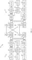
- FIG. 4 illustrates example components of the BS 110 and UE 120 illustrated in FIG. 1 , which may be used to implement aspects of the present disclosure.
- the BS may include a TRP.
- One or more components of the BS 110 and UE 120 may be used to practice aspects of the present disclosure.
- antennas 452, Tx/Rx 222, processors 466, 458, 464, and/or controller/processor 480 of the UE 120 and/or antennas 434, processors 420, 438, and/or controller/processor 440 of the BS 110 maybe used to perform the operations described herein and illustrated with reference to FIGs. 8 , and 9 .
- FIG. 4 shows a block diagram of a design of a BS 110 and a UE 120, which may be one of the BSs and one of the UEs in FIG. 1 .
- the base station 110 may be the macro BS 110c in FIG. 1
- the UE 120 may be the UE 120y.
- the base station 110 may also be a base station of some other type.
- the base station 110 may be equipped with antennas 434a through 434t, and the UE 120 maybe equipped with antennas 452a through 452r.
- a transmit processor 420 may receive data from a data source 412 and control information from a controller/processor 440.
- the control information may be for the Physical Broadcast Channel (PBCH), Physical Control Format Indicator Channel (PCFICH), Physical Hybrid ARQ Indicator Channel (PHICH), Physical Downlink Control Channel (PDCCH), etc.
- the data may be for the Physical Downlink Shared Channel (PDSCH), etc.
- the processor 420 may process (e.g., encode and symbol map) the data and control information to obtain data symbols and control symbols, respectively.
- the processor 420 may also generate reference symbols, e.g., for the PSS, SSS, and cell-specific reference signal.
- a transmit (TX) multiple-input multiple-output (MIMO) processor 430 may perform spatial processing (e.g., precoding) on the data symbols, the control symbols, and/or the reference symbols, if applicable, and may provide output symbol streams to the modulators (MODs) 432a through 432t.
- the TX MIMO processor 430 may perform certain aspects described herein for RS multiplexing.
- Each modulator 432 may process a respective output symbol stream (e.g., for OFDM, etc.) to obtain an output sample stream.
- Each modulator 432 may further process (e.g., convert to analog, amplify, filter, and upconvert) the output sample stream to obtain a downlink signal.
- Downlink signals from modulators 432a through 432t maybe transmitted via the antennas 434a through 434t, respectively.
- the antennas 452a through 452r may receive the downlink signals from the base station 110 and may provide received signals to the demodulators (DEMODs) 454a through 454r, respectively.
- Each demodulator 454 may condition (e.g., filter, amplify, downconvert, and digitize) a respective received signal to obtain input samples.
- Each demodulator 454 may further process the input samples (e.g., for OFDM, etc.) to obtain received symbols.
- a MIMO detector 456 may obtain received symbols from all the demodulators 454a through 454r, perform MIMO detection on the received symbols if applicable, and provide detected symbols. For example, MIMO detector 456 may provide detected RS transmitted using techniques described herein.
- a receive processor 458 may process (e.g., demodulate, deinterleave, and decode) the detected symbols, provide decoded data for the UE 120 to a data sink 460, and provide decoded control information to a controller/processor 480.
- CoMP aspects can include providing the antennas, as well as some Tx/Rx functionalities, such that they reside in distributed units. For example, some Tx/Rx processing can be done in the central unit, while other processing can be done at the distributed units. For example, in accordance with one or more aspects as shown in the diagram, the BS mod/demod 432 may be in the distributed units.
- a transmit processor 464 may receive and process data (e.g., for the Physical Uplink Shared Channel (PUSCH)) from a data source 462 and control information (e.g., for the Physical Uplink Control Channel (PUCCH) from the controller/processor 480.
- the transmit processor 464 may also generate reference symbols for a reference signal.
- the symbols from the transmit processor 464 may be precoded by a TX MIMO processor 466 if applicable, further processed by the demodulators 454a through 454r (e.g., for SC-FDM, etc.), and transmitted to the base station 110.
- the uplink signals from the UE 120 may be received by the antennas 434, processed by the modulators 432, detected by a MIMO detector 436 if applicable, and further processed by a receive processor 438 to obtain decoded data and control information sent by the UE 120.
- the receive processor 438 may provide the decoded data to a data sink 439 and the decoded control information to the controller/processor 440.
- the controllers/processors 440 and 480 may direct the operation at the base station 110 and the UE 120, respectively.
- the processor 440 and/or other processors and modules at the base station 110 may perform or direct the processes for the techniques described herein.
- the processor 480 and/or other processors and modules at the UE 120 may also perform or direct processes for the techniques described herein.
- the memories 442 and 482 may store data and program codes for the BS 110 and the UE 120, respectively.
- a scheduler 444 may schedule UEs for data transmission on the downlink and/or uplink.
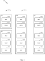
- FIG. 5 illustrates a diagram 500 showing examples for implementing a communications protocol stack, according to aspects of the present disclosure.
- the illustrated communications protocol stacks may be implemented by devices operating in a in a 5G system (e.g., a system that supports uplink-based mobility).
- Diagram 500 illustrates a communications protocol stack including a Radio Resource Control (RRC) layer 510, a Packet Data Convergence Protocol (PDCP) layer 515, a Radio Link Control (RLC) layer 520, a Medium Access Control (MAC) layer 525, and a Physical (PHY) layer 530.
- RRC Radio Resource Control
- PDCP Packet Data Convergence Protocol
- RLC Radio Link Control
- MAC Medium Access Control
- PHY Physical
- the layers of a protocol stack may be implemented as separate modules of software, portions of a processor or ASIC, portions of non-collocated devices connected by a communications link, or various combinations thereof. Collocated and non-collocated implementations may be used, for example, in a protocol stack for a network access device (e.g., ANs, CUs, and/or DUs) or a UE.
- a network access device e.g., ANs, CUs, and/or DUs
- a first option 505-a shows a split implementation of a protocol stack, in which implementation of the protocol stack is split between a centralized network access device (e.g., an ANC 202 in FIG. 2 ) and distributed network access device.
- a centralized network access device e.g., an ANC 202 in FIG. 2
- distributed network access device e.g., an ANC 202 in FIG. 2
- an RRC layer 510 and a PDCP layer 515 maybe implemented by the central unit
- an RLC layer 520, a MAC layer 525, and a PHY layer 530 may be implemented by the DU.
- the CU and the DU may be collocated or non-collocated.
- the first option 505-a may be useful in a macro cell, micro cell, or pico cell deployment.
- a second option 505-b shows a unified implementation of a protocol stack, in which the protocol stack is implemented in a single network access device (e.g., access node (AN), new radio base station (NR BS), a new radio Node-B (NR NB), a network node (NN), or the like.).
- the RRC layer 510, the PDCP layer 515, the RLC layer 520, the MAC layer 525, and the PHY layer 530 may each be implemented by the AN.
- the second option 505-b may be useful in a femto cell deployment.
- a UE may implement an entire protocol stack (e.g., the RRC layer 510, the PDCP layer 515, the RLC layer 520, the MAC layer 525, and the PHY layer 530).
- an entire protocol stack e.g., the RRC layer 510, the PDCP layer 515, the RLC layer 520, the MAC layer 525, and the PHY layer 530.
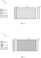
- FIG. 6 is a diagram 600 showing an example of a DL-centric subframe.
- the DL-centric subframe may include a control portion 602.
- the control portion 602 may exist in the initial or beginning portion of the DL-centric subframe.
- the control portion 602 may include various scheduling information and/or control information corresponding to various portions of the DL-centric subframe.
- the control portion 602 may be a physical DL control channel (PDCCH), as indicated in FIG. 6 .
- the DL-centric subframe may also include a DL data portion 604.
- the DL data portion 604 may sometimes be referred to as the payload of the DL-centric subframe.
- the DL data portion 604 may include the communication resources utilized to communicate DL data from the scheduling entity (e.g., UE or BS) to the subordinate entity (e.g., UE).
- the DL data portion 604 may be a physical DL shared channel (PDSCH).
- PDSCH physical DL shared channel
- the DL-centric subframe may also include a common UL portion 606.
- the common UL portion 606 may sometimes be referred to as an UL burst, a common UL burst, and/or various other suitable terms.
- the common UL portion 606 may include feedback information corresponding to various other portions of the DL-centric subframe.
- the common UL portion 606 may include feedback information corresponding to the control portion 602.
- Nonlimiting examples of feedback information may include an ACK signal, a NACK signal, a HARQ indicator, and/or various other suitable types of information.
- the common UL portion 606 may include additional or alternative information, such as information pertaining to random access channel (RACH) procedures, scheduling requests (SRs), and various other suitable types of information.
- RACH random access channel
- SRs scheduling requests
- the end of the DL data portion 604 may be separated in time from the beginning of the common UL portion 606.
- This time separation may sometimes be referred to as a gap, a guard period, a guard interval, and/or various other suitable terms.
- This separation provides time for the switch-over from DL communication (e.g., reception operation by the subordinate entity (e.g., UE)) to UL communication (e.g., transmission by the subordinate entity (e.g., UE)).
- DL communication e.g., reception operation by the subordinate entity (e.g., UE)
- UL communication e.g., transmission by the subordinate entity (e.g., UE)
- FIG. 7 is a diagram 700 showing an example of an UL-centric subframe.
- the UL -centric subframe may include a control portion 702.
- the control portion 702 may exist in the initial or beginning portion of the UL-centric subframe.
- the control portion 702 in FIG. 7 may be similar to the control portion described above with reference to FIG. 6 .
- the UL-centric subframe may also include an UL data portion 704.
- the UL data portion 704 may sometimes be referred to as the payload of the UL-centric subframe.
- the UL portion may refer to the communication resources utilized to communicate UL data from the subordinate entity (e.g., UE) to the scheduling entity (e.g., UE or BS).
- the control portion 702 may be a physical DL control channel (PDCCH).
- PDCH physical DL control channel
- the end of the control portion 702 may be separated in time from the beginning of the UL data portion 704. This time separation may sometimes be referred to as a gap, guard period, guard interval, and/or various other suitable terms. This separation provides time for the switch-over from DL communication (e.g., reception operation by the scheduling entity) to UL communication (e.g., transmission by the scheduling entity).
- the UL-centric subframe may also include a common UL portion 706.
- the common UL portion 706 in FIG. 7 maybe similar to the common UL portion 706 described above with reference to FIG. 7 .
- the common UL portion 706 may additional or alternative include information pertaining to channel quality indicator (CQI), sounding reference signals (SRSs), and various other suitable types of information.
- CQI channel quality indicator
- SRSs sounding reference signals
- two or more subordinate entities may communicate with each other using sidelink signals.
- Real-world applications of such sidelink communications may include public safety, proximity services, UE-to-network relaying, vehicle-to-vehicle (V2V) communications, Internet of Everything (IoE) communications, IoT communications, mission-critical mesh, and/or various other suitable applications.
- a sidelink signal may refer to a signal communicated from one subordinate entity (e.g., UE1) to another subordinate entity (e.g., UE2) without relaying that communication through the scheduling entity (e.g., UE or BS), even though the scheduling entity may be utilized for scheduling and/or control purposes.
- the sidelink signals may be communicated using a licensed spectrum (unlike wireless local area networks, which typically use an unlicensed spectrum).
- a UE may operate in various radio resource configurations, including a configuration associated with transmitting pilots using a dedicated set of resources (e.g., a radio resource control (RRC) dedicated state, etc.) or a configuration associated with transmitting pilots using a common set of resources (e.g., an RRC common state, etc.).
- RRC radio resource control
- the UE may select a dedicated set of resources for transmitting a pilot signal to a network.
- the UE may select a common set of resources for transmitting a pilot signal to the network.
- a pilot signal transmitted by the UE may be received by one or more network access devices, such as an AN, or a DU, or portions thereof.
- Each receiving network access device may be configured to receive and measure pilot signals transmitted on the common set of resources, and also receive and measure pilot signals transmitted on dedicated sets of resources allocated to the UEs for which the network access device is a member of a monitoring set of network access devices for the UE.
- One or more of the receiving network access devices, or a CU to which receiving network access device(s) transmit the measurements of the pilot signals may use the measurements to identify serving cells for the UEs, or to initiate a change of serving cell for one or more of the UEs.
- dual connectivity allows users to transmit and receive data from multiple TRPs independently and/or simultaneously.
- the UE may send and receive data from two TRPs in two separate streams when the UE is in range of two cell towers in two adjacent cells at the same time.
- the UE may communicate with the two towers simultaneously when the UE is within either towers' reach.
- dual connectivity may exploit network capacities.
- the UE may select one of the two TRPs to communicate with depending on the requirements of the UE. This helps improve the user experience while increasing network capacity.
- dual connectivity may have benefits in the cellular industry.
- DC can significantly improve per-user throughput and mobility robustness by allowing users to be connected simultaneously to an eNB and a gNB.
- the increase in per-user throughput is achieved by aggregating radio resources from at least two NBs.
- dual connectivity also helps in load balancing between the eNB and the gNB.
- an LTE-NR tight interworking architecture with dual connectivity may be used to avoid areas where NR does not have ubiquitous coverage.
- a sounding reference signal is a reference signal transmitted by a UE in the uplink direction.
- the SRS may be used by the base station (e.g., gNB or eNB) to estimate the uplink channel quality.
- the base station (BS) may use this information to schedule uplink frequency resources for the UE.
- Certain aspects of the present disclosure are generally directed to techniques for transmitting SRSs for the BS to estimate a channel.
- the SRSs may be transmitted by the UE via different antennas (e.g., downlink (DL) antennas) and using one or more transmit chains of the UE.
- DL downlink
- a special SRS slot (or a mini-slot) may be used to sound multiple (e.g., four) DL channels by sending reference symbols from the UE to the BS.
- the slot structure may be the same for all subcarrier spacing (SCS), but may be different if the SRS is shorter than the full symbol.
- SCS subcarrier spacing
- Certain aspects of the present disclosure provide different configurations for transmission of SRS for different UE capabilities.
- some UEs may have a single transmitter (e.g., a single power amplifier (PA)), indicated by a rank one transmission capability, some UEs may have two transmitters, indicated by a rank two transmission capability, and some UEs may have four transmitters, indicated by a rank three transmission capability.
- PA power amplifier
- two antennas may be sounded simultaneously
- four transmitters four antennas may be sounded simultaneously.
- FIG. 8 illustrates example operations 800 for wireless communication, in accordance with certain aspects of the present disclosure.
- the operations 800 may be performed by a UE, such as the UE 120 of FIG. 1 .
- the operations 800 begin, at block 802, by generating a plurality of SRSs, and at block 804, transmitting each of the plurality of SRSs via one of a plurality of antennas using at least one symbol of a slot in a subframe.
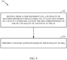
- FIG. 9 illustrates example operations 900 for wireless communication, in accordance with certain aspects of the present disclosure.
- the operations 900 may be performed by a network entity, such as the BS 110 of FIG. 1 .
- the operations 900 begin, at block 902, by receiving, from a UE (e.g., UE 120), a plurality of SRSs via at least one symbol of a slot in a subframe, each of the SRSs corresponding to one of a plurality of antennas at the UE, and at block 904, performing a channel estimate (e.g., MIMO sounding) based on the plurality of SRSs.
- a UE e.g., UE 120
- a channel estimate e.g., MIMO sounding
- the at least one symbol may include a plurality of symbols, and each of the plurality of SRSs may be transmitted using a different one of the plurality of symbols.
- each SRS may be transmitted using different symbols with a gap (e.g., of one symbol) between the different symbols, allowing the transmit path to be routed to a different antenna between the SRS transmissions, as described in more detail with respect to FIG. 10 .
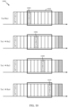
- FIG. 10 illustrates a protocol 1000 for transmitting SRS via different antennas (e.g., receiver (Rx) or DL antennas) for a UE having a single transmitter (e.g., a single PA), in accordance with certain aspects of the present disclosure.
- the protocol 1000 includes a slot 1002, having seven symbols, for transmitting SRSs.
- a transmitter (Tx1) may be used to transmit SRS 1004 via a first receive antenna (Rx1) during a first symbol in the slot 1002.
- a transmit path coupled to Tx1 may be rerouted from Tx1 to a second receive antenna (Rx2), prior to transmitting a SRS 1006 via the second receive antenna Rx2.
- one symbol gap may be present between the transmission of the SRS 1004 and the SRS 1006, as illustrated, allowing sufficient time for the rerouting (e.g., reconfiguring switches) of the transmit chain.
- the symbol duration for a 60 KHz subcarrier spacing may be around 17.8 us
- time for rerouting the transmit chain e.g., turning PA of the transmitter off, switching antennas by controlling one or more switches, and turning the PA on
- the transmit chain may be rerouted to a third receive antenna (Rx3) for transmission of SRS 1008, and subsequently rerouted to a fourth receive antennas (Rx4) for transmission of SRS 1010 in a similar manner.
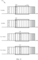
- FIG. 11 illustrates a protocol 1100 for transmitting SRS via different antennas (e.g., Rx or DL antennas) for a UE with two transmitters, in accordance with certain aspects of the present disclosure.
- the protocol 1100 includes a slot (e.g., including seven symbols), for transmitting SRSs.
- a mini slot with fewer symbols may be designated for SRS transmissions.
- a first transmitter may be used to transmit SRS 1104 via a first receive antenna (Rx1) during a first symbol in the slot 1102 and a second transmitter (Tx2) may be used to transmit SRS 1106 via a second receive antenna (Rx2) during the first symbol (e.g., simultaneously with the transmission of SRS 1104).
- Transmit paths coupled to Tx1 and Tx2 may then be rerouted from Tx1 to a third receive antenna (Rx3) and from Tx2 to a fourth receive antenna (Rx4), prior to the first transmitter transmitting a SRS 1108 via Rx3 and the second transmitter transmitting a SRS 1110 via Rx4. Therefore, one symbol gap maybe present prior to the transmission of the SRSs 1108 and 1110, as illustrated, allowing sufficient time for the rerouting of the transmit chains.
- each of the transmitters Tx1 and Tx2 may transmit SRSs via different antennas during the same symbol.
- the symbol duration may be about 35.6 us (e.g., as opposed to only 17.8 us for a 60 KHz subcarrier spacing).
- This longer subcarrier spacing may provide sufficient time for the rerouting of the transmit path and transmission of SRSs via multiple antennas during the same symbol.
- SRSs may be transmitted via two antennas if the number of tones required is less than half the symbol duration.
- two transmitters may transmit SRSs via four antennas in the same symbol. This is also possible for a case where the UE has four transmitters.
- each transmitter may transmit an SRS using one of the four antennas simultaneously.
- the protocol 1100 may be used for UL MIMO. If UL MIMO is not configured, the network can either configure UL MIMO and then request SRS sequence transmission according to protocol 1100 or request SRS sequence transmission according to protocol 1000 described with respect to FIG. 10 .
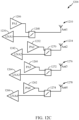
- FIGs. 12A, 12B , and 12C illustrate different architectures of radio-frequency (RF) front-end circuitry 1200, 1202, 1204 having one, two, or four PAs, respectively, in accordance with certain aspects of the present disclosure.
- the RF front-end circuitry 1200 includes a single PA 1206 and is configured with switch circuitry 1208 (e.g., a duplexer) to allow for the output of the PA 1206 to be coupled to one of multiple antennas 1210, 1212, 1214, 1216, and moreover, to couple the antenna 1210 to the low-noise amplifier (LNA) 1230 during reception.
- switch circuitry 1208 e.g., a duplexer
- antennas 1210 may be designated for both uplink and downlink (hereinafter referred to a transmit (TX) antenna), and thus, may be in close proximity to the PA 1206 used to amplify signals for transmission.
- antennas 1212, 1214, 1216 may be receive (Rx) antennas designated for downlink communications, and thus, may not be in close proximity to any PA (e.g., PA 1206).
- PA 1206 may be used to transmit SRSs via the antennas 1212, 1214, 1216 using switches 1218, 1220, 1222, as illustrated.
- switch circuitry 1208 may be configured to route a signal generated by the PA 1206 to one of the switches 1218, 1220, 1222.
- Each of the switches 1218, 1220, 1222 may be configured to route a signal from the switch circuitry 1208 to a respective one of the antennas 1212, 1214, 1216.
- the switches 1218, 1220, 1222 may also be configured to connect a respective one of the antennas 1212, 1214, 1216 to LNAs 1224, 1226, 1228 during reception.
- the RF circuitry 1200 may allow for a single SRS transmission via one of the antennas 1210, 1212, 1214, 1216 at any point in time, as described with respect to FIG. 10 .
- the RF front-end circuitry 1202 includes two PAs 1206, 1232.
- antennas 1210, 1234 may be TX antennas and antennas 1212, 1236 may be RX antennas.
- PA 1206 may be used for SRS transmissions using antennas 1210, 1212
- PA 1232 may be used for SRS transmissions using antennas 1234, 1236.
- the PA 1232 may be coupled to switch circuitry 1238 (e.g., a duplexer) to allow for the output of the PA 1232 to be coupled to one of antennas 1234, 1236, through switch 1240.
- the switch circuitry 1238 and switch 1240 may be configured to connect respective one of antennas 1234, 1236 to a respective one of the LNAs 1242, 1244 during reception.
- the RF circuitry 1202 may allow for two SRS transmissions via two of the antennas (e.g., antennas 1212 and 1236) at any point in time, as described with respect to FIG. 11 .
- the RF front-end circuitry 1202 includes four PAs 1206, 1232, 1260, 1262, each coupled to a respective one of antennas 1210, 1234, 1276, 1278, through a respective one of switches 1268, 1270, 1272, 1274.
- the switches 1268, 1270, 1272, 1274 may also be configured to couple a respective one of the antennas 1210, 1234, 1276, 1278 to a respective one of the LNAs 1230, 1242, 1264, 1266 during reception, as illustrated.
- the RF circuitry 1204 may allow for four SRS transmissions via the antennas 1210, 1234, 1276, 1278 at any point in time.
- multiple subbands may be sounded.
- the time needed to switch between subbands may be 20 microseconds for bandwidth (BW) reconfiguration, plus 50-200 microseconds for retuning the local oscillator (LO) signal of the RF chain, and up to 900 microseconds for changing bands.
- BW bandwidth
- LO local oscillator
- these operations may be performed in parallel with the antenna switching, as previously described.
- One option for sounding multiple subbands is to configure the UE to wide bandwidth mode spanning the multiple bands. In this case, BW reconfiguration and LO retuning may not be needed if the UE supports the intended full frequency range for SRS configurations, and thus, the frame structures described with respect to protocols 1000 and 1100 may be used.
- Certain aspects of the present disclosure provide protocols for transmission of SRSs for a UE that supports UL carrier-aggregation (CA).
- CA carrier-aggregation
- For inter-band CA e.g., when component carriers (CCs) are in different bands
- CCs component carriers
- SRS communication may be performed in accordance with the protocols 1000 or 1100 described with respect to FIGs. 10 and 11 .
- TX transmit
- CC1 first component carrier
- CC2 second component carrier
- the TX chain may be configured to the first component carrier CC1 mode only, at which point the protocols 1000 and 1110 as described with respect to FIGs. 10 and 11 maybe used for SRS transmissions.
- SRS maybe transmitted using the TX antenna (e.g., antenna 1210 in FIG. 12A ) first, before configuring the TX chain to CC1 only for SRS transmissions using the RX antennas (e.g., antennas 1212, 1214, 1216 in FIG. 12A ).
- TX antenna e.g., antenna 1210 in FIG. 12A
- RX antennas e.g., antennas 1212, 1214, 1216 in FIG. 12A
- any transmission including a SRS on a primary cell (PCell) may be sent to the same antenna port as the secondary cell (SCell).
- PCell primary cell
- SCell secondary cell
- the UE supports UL CA and UL MIMO two antenna ports may be sounded simultaneously, but all CCs may be sent to the same antenna ports.
- Similar patterns for SRS transmissions as described with respect to protocols 1000 and 1100 may be applied for two the PA scenario as described herein if UL MIMO is configured. If not UL MIMO is not configured, then the network may configure UL MIMO before scheduling SRS transmissions or schedule single TX SRS pattern as described with respect to protocol 1000 of FIG. 10 . In this case, one PA could be used for SRS transmissions and the other PA may be used for other transmissions on the other CC. However, for UL MIMO and for contiguous intra-band UL CA, the TX chains may share the same LO. Thus, even if the UE supports UL MIMO and UL CA, the UE may still be unable to send different signals to different antenna ports. If a UE has two TX LOs, then independent SRS and CC transmissions may be implemented.
- Switching a PA to secondary or RX antennas involves using additional components or traces between the PA and the RX antennas, as descried herein, which results in additional losses from the PA to the corresponding antenna connectors.
- the multi output switches described with respect to FIGs. 12A, 12B , and 12C may be configured for low insertion losses between the PA and primary TX antenna (e.g., from PA 1206 to antenna 1210 of FIG 12A ).
- the MIMO antennas e.g., antennas 1214 and 1216 of FIG. 12A
- routing losses e.g., up to 3 dB. It may be difficult to distinguish by standard which antennas will experience largest losses.
- an offset parameter may be used to reduce the maximum output power of the SRS transmission (e.g., by 3 dB) when non-TX antenna(s) are sounded.
- this parameter may be band dependent.
- FIG. 13 illustrates example operations 1300 for wireless communication, in accordance with certain aspects of the present disclosure.
- the operations 1300 may be performed by, for example, a UE such as the UE 120 of FIG. 1 .
- the operations 1300 begin, at block 1302, by determining a transmission power for each of at least one first SRS to be transmitted using at least one first antenna (e.g., RX antennas such as antennas 1214 and 1216 of FIG. 12A ). In this case, the determination may be based on whether the at least one first SRS is transmitted using an amplifier (e.g., PA 1206) of a transmit chain configured for transmissions using a second antenna (e.g., a TX antenna such as antenna 1210 of FIG. 12A ). At block 1304, the UE may transmit the at least one first SRS based on the determination.
- an amplifier e.g., PA 1206
- a transmit chain e.g., a TX antenna such as antenna 1210 of FIG. 12A
- P EMAX, c is the maximum allowable uplink emission power as set by the network
- P PowerClass is the maximum RF output power of the UE (dBm) according to the UE power class
- ⁇ P PowerClass is an offset to the maximum RF output power that may be set by the UE
- MPR c is the maximum power reduction (MPR)
- A-MPR c is additional-MPR that may be set by the UE
- P-MPR c is a
- ⁇ TRxSRS may be set to adjust (e.g., relax) the maximum output power setting to account for losses due to sounding on a non-TX antenna(s).
- ⁇ T RxSRS may be set to 3 dB and may be applied when the UE transmits SRS to antenna ports designated as Rx ports (e.g., antennas 1214 and 1216 of FIG. 12A ).
- the UE may know the additional loss from the PA to the RX antenna ports since this loss may be design dependent.
- the UE may compensates for the additional loss at lower power levels and aim to deliver SRSs to all antennas ports with equal power.
- PA 1206 may be configured to transmit SRSs via antennas 1210, 1212, 1214, and 1216 with the same power by compensating for the power loss differences between the routing of signals from the PA 1206 to each of the antennas 1210, 1212, 1214, and 1216.
- compensating for the additional power loss may only be possible until a maximum power capability of the PA 1206 is reached, at which point, the power of SRSs may begin to differ.
- the UE may maintain the same power difference between antennas as indicated by the maximum power capability reduction throughout the entire power range of the PA 1206.
- PA 1206 may be configured to transmit SRSs using the Rx antennas (e.g., antennas 1212, 1214, and 1216) at 3dB lower power as compared to an SRS transmitted using the TX antenna (e.g., antenna 1210).
- certain aspects of the present disclosure are directed to techniques for a network to determine whether a UE is capable of compensation for the power loss and indicate to the UE if the network prefers for the UE to compensate for the SRS power and allow degradation only when the maximum power is reached, or if the network prefers for the UE to maintain the same power difference between antennas regardless of the power level until a maximum power is reached.
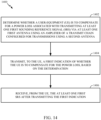
- FIG. 14 illustrates example operations 1400 for wireless communication, in accordance with certain aspects of the present disclosure.
- the operations 1400 may be performed by, for example, a network entity such as the BS 110 of FIG. 1 .
- the operations 1400 begin, at block 1402, by determining whether a UE is to compensate for a power loss associated with transmitting at least one first SRS via at least one first antenna (e.g., antenna 1212) using an amplifier (e.g., PA 1206) of a transmit chain configured for transmissions using a second antenna (e.g., antenna 1210).
- the network entity may transmit, to the UE, a first indication of whether the UE is to compensate for the power loss, based on the determination, and at block 1406, receive, from the UE, the at least one first SRS after transmitting the first indication.
- the network entity may receive, from the UE, a second indication of whether the UE is capable of compensating for the power loss. In this case, the determination at block 1402 may be based on the second indication.
- the methods disclosed herein comprise one or more steps or actions for achieving the described method.
- the method steps and/or actions may be interchanged with one another without departing from the scope of the claims.
- the order and/or use of specific steps and/or actions may be modified without departing from the scope of the claims.
- a phrase referring to "at least one of" a list of items refers to any combination of those items, including single members.
- "at least one of: a, b, or c” is intended to cover a, b, c, a-b, a-c, b-c, and a-b-c, as well as any combination with multiples of the same element (e.g., a-a, a-a-a, a-a-b, a-a-c, a-b-b, a-c-c, b-b, b-b-b, b-b-c, c-c, and c-c-c or any other ordering of a, b, and c).
- the term "and/or,” when used in a list of two or more items, means that any one of the listed items can be employed by itself, or any combination of two or more of the listed items can be employed.
- the composition can contain A alone; B alone; C alone; A and B in combination; A and C in combination; B and C in combination; or A, B, and C in combination.
- determining encompasses a wide variety of actions. For example, “determining” may include calculating, computing, processing, deriving, investigating, looking up (e.g., looking up in a table, a database or another data structure), ascertaining and the like. Also, “determining” may include receiving (e.g., receiving information), accessing (e.g., accessing data in a memory) and the like. Also, “determining” may include resolving, selecting, choosing, establishing and the like.
- the term "or” is intended to mean an inclusive “or” rather than an exclusive “or.” That is, unless specified otherwise, or clear from the context, the phrase, for example, "X employs A or B” is intended to mean any of the natural inclusive permutations. That is, for example the phrase “X employs A or B” is satisfied by any of the following instances: X employs A; X employs B; or X employs both A and B. Moreover, nothing disclosed herein is intended to be dedicated to the public regardless of whether such disclosure is explicitly recited in the claims.
- the various operations of methods described above may be performed by any suitable means capable of performing the corresponding functions.
- the means may include various hardware and/or software component(s) and/or module(s), including, but not limited to a circuit, an application specific integrated circuit (ASIC), or processor.
- ASIC application specific integrated circuit
- DSP digital signal processor
- ASIC application specific integrated circuit
- FPGA field programmable gate array
- PLD programmable logic device
- a general-purpose processor may be a microprocessor, but in the alternative, the processor may be any commercially available processor, controller, microcontroller, or state machine.
- a processor may also be implemented as a combination of computing devices, e.g., a combination of a DSP and a microprocessor, a plurality of microprocessors, one or more microprocessors in conjunction with a DSP core, or any other such configuration.
- an example hardware configuration may comprise a processing system in a wireless node.
- the processing system may be implemented with a bus architecture.
- the bus may include any number of interconnecting buses and bridges depending on the specific application of the processing system and the overall design constraints.
- the bus may link together various circuits including a processor, machine-readable media, and a bus interface.
- the bus interface may be used to connect a network adapter, among other things, to the processing system via the bus.
- the network adapter may be used to implement the signal processing functions of the PHY layer.
- a user interface e.g., keypad, display, mouse, joystick, etc.
- the bus may also link various other circuits such as timing sources, peripherals, voltage regulators, power management circuits, and the like, which are well known in the art, and therefore, will not be described any further.
- the processor may be implemented with one or more general-purpose and/or special-purpose processors. Examples include microprocessors, microcontrollers, DSP processors, and other circuitry that can execute software. Those skilled in the art will recognize how best to implement the described functionality for the processing system depending on the particular application and the overall design constraints imposed on the overall system.
- Computer-readable media include both computer storage media and communication media including any medium that facilitates transfer of a computer program from one place to another.
- the processor may be responsible for managing the bus and general processing, including the execution of software modules stored on the machine-readable storage media.
- a computer-readable storage medium may be coupled to a processor such that the processor can read information from, and write information to, the storage medium. In the alternative, the storage medium may be integral to the processor.
- the machine-readable media may include a transmission line, a carrier wave modulated by data, and/or a computer readable storage medium with instructions stored thereon separate from the wireless node, all of which may be accessed by the processor through the bus interface.
- the machine-readable media, or any portion thereof may be integrated into the processor, such as the case may be with cache and/or general register files.
- machine-readable storage media may include, by way of example, RAM (Random Access Memory), flash memory, phase change memory, ROM (Read Only Memory), PROM (Programmable Read-Only Memory), EPROM (Erasable Programmable Read-Only Memory), EEPROM (Electrically Erasable Programmable Read-Only Memory), registers, magnetic disks, optical disks, hard drives, or any other suitable storage medium, or any combination thereof.
- RAM Random Access Memory
- flash memory Phase change memory
- ROM Read Only Memory
- PROM Programmable Read-Only Memory
- EPROM Erasable Programmable Read-Only Memory
- EEPROM Electrically Erasable Programmable Read-Only Memory
- registers magnetic disks, optical disks, hard drives, or any other suitable storage medium, or any combination thereof.
- the machine-readable media may be embodied in a computer-program product.
- a software module may comprise a single instruction, or many instructions, and may be distributed over several different code segments, among different programs, and across multiple storage media.
- the computer-readable media may comprise a number of software modules.
- the software modules include instructions that, when executed by an apparatus such as a processor, cause the processing system to perform various functions.
- the software modules may include a transmission module and a receiving module. Each software module may reside in a single storage device or be distributed across multiple storage devices.
- a software module may be loaded into RAM from a hard drive when a triggering event occurs.
- the processor may load some of the instructions into cache to increase access speed.
- One or more cache lines may then be loaded into a general register file for execution by the processor.
- any connection is properly termed a computer-readable medium.
- the software is transmitted from a website, server, or other remote source using a coaxial cable, fiber optic cable, twisted pair, digital subscriber line (DSL), or wireless technologies such as infrared (IR), radio, and microwave
- the coaxial cable, fiber optic cable, twisted pair, DSL, or wireless technologies such as infrared, radio, and microwave are included in the definition of medium.
- Disk and disc include compact disc (CD), laser disc, optical disc, digital versatile disc (DVD), floppy disk, and Blu-ray ® disc where disks usually reproduce data magnetically, while discs reproduce data optically with lasers.
- computer-readable media may comprise non-transitory computer-readable media (e.g., tangible media).
- computer-readable media may comprise transitory computer- readable media (e.g., a signal). Combinations of the above should also be included within the scope of computer-readable media.
- certain aspects may comprise a computer program product for performing the operations presented herein.
- a computer program product may comprise a computer-readable medium having instructions stored (and/or encoded) thereon, the instructions being executable by one or more processors to perform the operations described herein.
- instructions for performing the operations described herein and illustrated in the appended figures may comprise a computer-readable medium having instructions stored (and/or encoded) thereon, the instructions being executable by one or more processors to perform the operations described herein.
- modules and/or other appropriate means for performing the methods and techniques described herein can be downloaded and/or otherwise obtained by a user terminal and/or base station as applicable.
- a user terminal and/or base station can be coupled to a server to facilitate the transfer of means for performing the methods described herein.
- various methods described herein can be provided via storage means (e.g., RAM, ROM, a physical storage medium such as a compact disc (CD) or floppy disk, etc.), such that a user terminal and/or base station can obtain the various methods upon coupling or providing the storage means to the device.
- storage means e.g., RAM, ROM, a physical storage medium such as a compact disc (CD) or floppy disk, etc.
- CD compact disc
- floppy disk etc.
- any other suitable technique for providing the methods and techniques described herein to a device can be utilized.
Landscapes
- Engineering & Computer Science (AREA)
- Signal Processing (AREA)
- Computer Networks & Wireless Communication (AREA)
- Mobile Radio Communication Systems (AREA)
- Radar Systems Or Details Thereof (AREA)
- Measuring Pulse, Heart Rate, Blood Pressure Or Blood Flow (AREA)
- Transmitters (AREA)
Applications Claiming Priority (4)
| Application Number | Priority Date | Filing Date | Title |
|---|---|---|---|
| US201762521864P | 2017-06-19 | 2017-06-19 | |
| US201762556740P | 2017-09-11 | 2017-09-11 | |
| US16/011,261 US11026189B2 (en) | 2017-06-19 | 2018-06-18 | Sounding reference signal (SRS) transmission protocol |
| PCT/US2018/038220 WO2018236826A1 (en) | 2017-06-19 | 2018-06-19 | Sounding reference signal (srs) transmission protocol |
Publications (2)
| Publication Number | Publication Date |
|---|---|
| EP3643124A1 EP3643124A1 (en) | 2020-04-29 |
| EP3643124B1 true EP3643124B1 (en) | 2023-08-09 |
Family
ID=64657864
Family Applications (1)
| Application Number | Title | Priority Date | Filing Date |
|---|---|---|---|
| EP18740697.0A Active EP3643124B1 (en) | 2017-06-19 | 2018-06-19 | Sounding reference signal (srs) transmission protocol |
Country Status (9)
| Country | Link |
|---|---|
| US (1) | US11026189B2 (enExample) |
| EP (1) | EP3643124B1 (enExample) |
| JP (1) | JP7076480B2 (enExample) |
| KR (1) | KR102337336B1 (enExample) |
| CN (1) | CN110754118B (enExample) |
| BR (1) | BR112019026327A2 (enExample) |
| SG (1) | SG11201910279WA (enExample) |
| TW (1) | TWI781185B (enExample) |
| WO (1) | WO2018236826A1 (enExample) |
Families Citing this family (24)
| Publication number | Priority date | Publication date | Assignee | Title |
|---|---|---|---|---|
| WO2020141647A1 (ko) * | 2019-01-04 | 2020-07-09 | 엘지전자 주식회사 | Srs를 지원하는 이동 단말기 및 그 이동 단말기의 제어 방법 |
| JP6956755B2 (ja) * | 2019-02-25 | 2021-11-02 | アンリツ株式会社 | 移動端末試験装置とそのサポート組合せ取得方法 |
| CN111669205B (zh) * | 2019-03-07 | 2021-08-17 | 荣耀终端有限公司 | 一种信道测量方法及设备 |
| US11245552B2 (en) * | 2019-03-29 | 2022-02-08 | Skyworks Solutions, Inc. | Sounding reference signal switching |
| WO2021031028A1 (zh) * | 2019-08-16 | 2021-02-25 | 华为技术有限公司 | 一种用于信号发送的方法、装置以及用于信号接收的方法、装置 |
| KR20210066691A (ko) * | 2019-11-28 | 2021-06-07 | 삼성전자주식회사 | 채널 상호성을 위한 사운딩 참조 신호의 송신 전력을 제어하는 무선 통신 장치 및 이를 포함하는 무선 통신 시스템 |
| EP3829076A3 (en) * | 2019-11-28 | 2021-08-04 | Samsung Electronics Co., Ltd. | Transmission power control of sounding reference signals in wireless communication system and device |
| CN110891305B (zh) * | 2019-12-11 | 2022-04-19 | 维沃移动通信有限公司 | 一种功率控制装置、方法及电子设备 |
| CN111342847B (zh) * | 2020-02-13 | 2021-11-30 | 芯朴科技(上海)有限公司 | 调整输出功率的方法 |
| CN113316243B (zh) * | 2020-02-27 | 2025-09-12 | 中兴通讯股份有限公司 | 同步信号的发送方法、电子设备及存储介质 |
| US11015156B1 (en) | 2020-05-22 | 2021-05-25 | Franzenburg | Protein concentration methods |
| CN111628801B (zh) * | 2020-05-28 | 2022-02-01 | 维沃移动通信有限公司 | 射频前端器件控制方法及用户设备 |
| CN111669199A (zh) * | 2020-06-08 | 2020-09-15 | 维沃移动通信有限公司 | 功率检测电路及电子设备 |
| KR20210152860A (ko) * | 2020-06-09 | 2021-12-16 | 삼성전자주식회사 | 복수의 증폭기를 이용한 신호의 증폭을 수행하는 통신 회로와 그것을 구비한 전자 장치 |
| CN111682885B (zh) * | 2020-06-09 | 2022-10-04 | 芯朴科技(上海)有限公司 | 1t2r射频电路、无线通信设备 |
| CN113824455B (zh) * | 2020-06-18 | 2023-04-07 | 华为技术有限公司 | 一种控制天线输出功率的方法、介质及设备 |
| CN113972940B (zh) * | 2020-07-22 | 2025-08-05 | 中兴通讯股份有限公司 | 频分双工系统的探测参考信号传输方法及终端 |
| CN114071748A (zh) * | 2020-08-07 | 2022-02-18 | 大唐移动通信设备有限公司 | 信号传输方法、终端和网络设备 |
| WO2022139847A1 (en) * | 2020-12-24 | 2022-06-30 | Google Llc | Adaptive sounding reference signal mapping for improved channel estimation |
| US12375333B2 (en) | 2021-06-14 | 2025-07-29 | Skyworks Solutions, Inc. | Sounding reference signal switching system |
| US20230119378A1 (en) * | 2021-10-15 | 2023-04-20 | Skyworks Solutions, Inc. | Multiple antenna transmission to manage radiated power |
| WO2023068530A1 (ko) * | 2021-10-18 | 2023-04-27 | 삼성전자 주식회사 | 전력 증폭기의 출력을 제어하는 전자 장치 |
| WO2024166082A1 (en) * | 2023-03-31 | 2024-08-15 | Lenovo (Singapore) Pte. Ltd. | Managing sounding reference signal symbol transmit power imbalance |
| WO2024201446A1 (en) * | 2023-05-12 | 2024-10-03 | Lenovo (Singapore) Pte. Ltd. | Method and apparatus for correcting srs-based downlink channel estimates based on an indication of whether power relaxation is compensated for an uplink transmission |
Citations (3)
| Publication number | Priority date | Publication date | Assignee | Title |
|---|---|---|---|---|
| US20100285762A1 (en) * | 2009-05-05 | 2010-11-11 | Hyunsoo Ko | Method of transmitting reference signal in multiple antenna system |
| US20120121031A1 (en) * | 2010-11-15 | 2012-05-17 | Futurewei Technologies, Inc. | Method and Apparatus for Demodulation of a Reference Signal |
| US20140050182A1 (en) * | 2011-07-13 | 2014-02-20 | Panasonic Corporation | Terminal apparatus, base station apparatus, transmission method and reception method |
Family Cites Families (12)
| Publication number | Priority date | Publication date | Assignee | Title |
|---|---|---|---|---|
| KR101639810B1 (ko) * | 2009-01-13 | 2016-07-25 | 엘지전자 주식회사 | 무선통신 시스템에서 사운딩 참조신호의 전송방법 |
| KR101612550B1 (ko) * | 2009-05-05 | 2016-04-19 | 엘지전자 주식회사 | 다중안테나 시스템에서 참조신호 전송방법 |
| MY161646A (en) * | 2009-10-02 | 2017-04-28 | Interdigital Patent Holdings Inc | Power control for devices having multiple antennas |
| US8958838B2 (en) * | 2010-02-12 | 2015-02-17 | Qualcomm Incorporated | Multi-stage transmit power control scheme for access point |
| KR101758592B1 (ko) * | 2011-07-29 | 2017-07-14 | 후지쯔 가부시끼가이샤 | 파워 제어 방법 및 단말 장치 |
| US9900849B2 (en) * | 2011-10-03 | 2018-02-20 | Qualcomm Incorporated | SRS optimization for coordinated multi-point transmission and reception |
| US9204434B2 (en) * | 2012-03-19 | 2015-12-01 | Qualcomm Incorporated | Enhanced sounding reference signal (SRS) operation |
| US9596065B2 (en) * | 2012-10-24 | 2017-03-14 | Qualcomm Incorporated | Enhanced SRS transmission for MIMO operation in LTE-A |
| EP3016301B1 (en) * | 2013-06-24 | 2019-12-18 | LG Electronics Inc. | Method for controlling transmission power of sounding reference signal in wireless communication system and apparatus for same |
| JP5948376B2 (ja) | 2014-07-30 | 2016-07-06 | 株式会社Nttドコモ | ユーザ端末、無線基地局及び無線通信方法 |
| CN108292940B (zh) * | 2015-12-16 | 2021-03-23 | 瑞士优北罗股份有限公司 | 收发器装置、调制解调器、通信装置和处理信号的方法 |
| MX2019005327A (es) * | 2017-04-27 | 2019-08-12 | Lg Electronics Inc | Metodo de transmision de srs y terminal para el mismo. |
-
2018
- 2018-06-18 US US16/011,261 patent/US11026189B2/en active Active
- 2018-06-19 TW TW107120964A patent/TWI781185B/zh active
- 2018-06-19 WO PCT/US2018/038220 patent/WO2018236826A1/en not_active Ceased
- 2018-06-19 SG SG11201910279WA patent/SG11201910279WA/en unknown
- 2018-06-19 JP JP2019569753A patent/JP7076480B2/ja active Active
- 2018-06-19 BR BR112019026327-6A patent/BR112019026327A2/pt unknown
- 2018-06-19 KR KR1020197037194A patent/KR102337336B1/ko active Active
- 2018-06-19 EP EP18740697.0A patent/EP3643124B1/en active Active
- 2018-06-19 CN CN201880039961.XA patent/CN110754118B/zh active Active
Patent Citations (3)
| Publication number | Priority date | Publication date | Assignee | Title |
|---|---|---|---|---|
| US20100285762A1 (en) * | 2009-05-05 | 2010-11-11 | Hyunsoo Ko | Method of transmitting reference signal in multiple antenna system |
| US20120121031A1 (en) * | 2010-11-15 | 2012-05-17 | Futurewei Technologies, Inc. | Method and Apparatus for Demodulation of a Reference Signal |
| US20140050182A1 (en) * | 2011-07-13 | 2014-02-20 | Panasonic Corporation | Terminal apparatus, base station apparatus, transmission method and reception method |
Also Published As
| Publication number | Publication date |
|---|---|
| BR112019026327A2 (pt) | 2020-07-21 |
| TW201907692A (zh) | 2019-02-16 |
| JP2020524444A (ja) | 2020-08-13 |
| KR20200014794A (ko) | 2020-02-11 |
| CN110754118A (zh) | 2020-02-04 |
| US20180368078A1 (en) | 2018-12-20 |
| EP3643124A1 (en) | 2020-04-29 |
| WO2018236826A1 (en) | 2018-12-27 |
| CN110754118B (zh) | 2022-10-28 |
| TWI781185B (zh) | 2022-10-21 |
| US11026189B2 (en) | 2021-06-01 |
| KR102337336B1 (ko) | 2021-12-08 |
| SG11201910279WA (en) | 2020-01-30 |
| JP7076480B2 (ja) | 2022-05-27 |
Similar Documents
| Publication | Publication Date | Title |
|---|---|---|
| EP3643124B1 (en) | Sounding reference signal (srs) transmission protocol | |
| EP3524020B1 (en) | Techniques for power control and management | |
| EP3579453B1 (en) | Beam correspondence indication, ue calibration indication, and synchronization information for tdd rach procedure | |
| EP3909185B1 (en) | Collision of sounding reference signal (srs) and physical uplink shared channel (pusch) in case of carrier aggregation | |
| EP3536015B1 (en) | Methods and apparatus for setting subband csi-related parameters | |
| WO2018127160A1 (en) | Transmitting sounding reference signals in new radio | |
| EP3669482A1 (en) | Frequency division multiplexing synchronization signals (ss) for wideband operation | |
| US10355743B2 (en) | Frequency hopping design for large bandwidth allocations in eMTC | |
| WO2019036692A1 (en) | UPLINK POWER CONTROL | |
| WO2019062726A1 (en) | FLOW ADAPTATION FOR SHARED PHYSICAL CHANNEL (PDSCH) AND SHARED PHYSICAL CHANNEL AMOUNT (PUSCH) NEW RADIO (NR) | |
| WO2018191250A1 (en) | Inter-radio access technology (rat), inter-band, or inter-carrier switching based on power consumption | |
| EP3602908A1 (en) | Radio resource control (rrc) entity selection for rrc messages | |
| EP3577845B1 (en) | Method and apparatus for retuning in machine type communications | |
| EP3718351B1 (en) | Power control for dual radio access technology (rat) communication | |
| CA3076825C (en) | Timing advance granularity for uplink with different numerologies | |
| HK40021201A (en) | Sounding reference signal (srs) transmission protocol | |
| HK40021201B (en) | Sounding reference signal (srs) transmission protocol | |
| CA3076825A1 (en) | Timing advance granularity for uplink with different numerologies |
Legal Events
| Date | Code | Title | Description |
|---|---|---|---|
| STAA | Information on the status of an ep patent application or granted ep patent |
Free format text: STATUS: UNKNOWN |
|
| STAA | Information on the status of an ep patent application or granted ep patent |
Free format text: STATUS: THE INTERNATIONAL PUBLICATION HAS BEEN MADE |
|
| PUAI | Public reference made under article 153(3) epc to a published international application that has entered the european phase |
Free format text: ORIGINAL CODE: 0009012 |
|
| STAA | Information on the status of an ep patent application or granted ep patent |
Free format text: STATUS: REQUEST FOR EXAMINATION WAS MADE |
|
| 17P | Request for examination filed |
Effective date: 20191106 |
|
| AK | Designated contracting states |
Kind code of ref document: A1 Designated state(s): AL AT BE BG CH CY CZ DE DK EE ES FI FR GB GR HR HU IE IS IT LI LT LU LV MC MK MT NL NO PL PT RO RS SE SI SK SM TR |
|
| AX | Request for extension of the european patent |
Extension state: BA ME |
|
| DAV | Request for validation of the european patent (deleted) | ||
| DAX | Request for extension of the european patent (deleted) | ||
| STAA | Information on the status of an ep patent application or granted ep patent |
Free format text: STATUS: EXAMINATION IS IN PROGRESS |
|
| 17Q | First examination report despatched |
Effective date: 20211013 |
|
| GRAP | Despatch of communication of intention to grant a patent |
Free format text: ORIGINAL CODE: EPIDOSNIGR1 |
|
| STAA | Information on the status of an ep patent application or granted ep patent |
Free format text: STATUS: GRANT OF PATENT IS INTENDED |
|
| INTG | Intention to grant announced |
Effective date: 20230224 |
|
| GRAS | Grant fee paid |
Free format text: ORIGINAL CODE: EPIDOSNIGR3 |
|
| GRAA | (expected) grant |
Free format text: ORIGINAL CODE: 0009210 |
|
| STAA | Information on the status of an ep patent application or granted ep patent |
Free format text: STATUS: THE PATENT HAS BEEN GRANTED |
|
| AK | Designated contracting states |
Kind code of ref document: B1 Designated state(s): AL AT BE BG CH CY CZ DE DK EE ES FI FR GB GR HR HU IE IS IT LI LT LU LV MC MK MT NL NO PL PT RO RS SE SI SK SM TR |
|
| REG | Reference to a national code |
Ref country code: GB Ref legal event code: FG4D |
|
| REG | Reference to a national code |
Ref country code: CH Ref legal event code: EP |
|
| REG | Reference to a national code |
Ref country code: DE Ref legal event code: R096 Ref document number: 602018055004 Country of ref document: DE |
|
| REG | Reference to a national code |
Ref country code: IE Ref legal event code: FG4D |
|
| REG | Reference to a national code |
Ref country code: LT Ref legal event code: MG9D |
|
| REG | Reference to a national code |
Ref country code: NL Ref legal event code: MP Effective date: 20230809 |
|
| REG | Reference to a national code |
Ref country code: AT Ref legal event code: MK05 Ref document number: 1598953 Country of ref document: AT Kind code of ref document: T Effective date: 20230809 |
|
| PG25 | Lapsed in a contracting state [announced via postgrant information from national office to epo] |
Ref country code: GR Free format text: LAPSE BECAUSE OF FAILURE TO SUBMIT A TRANSLATION OF THE DESCRIPTION OR TO PAY THE FEE WITHIN THE PRESCRIBED TIME-LIMIT Effective date: 20231110 |
|
| PG25 | Lapsed in a contracting state [announced via postgrant information from national office to epo] |
Ref country code: IS Free format text: LAPSE BECAUSE OF FAILURE TO SUBMIT A TRANSLATION OF THE DESCRIPTION OR TO PAY THE FEE WITHIN THE PRESCRIBED TIME-LIMIT Effective date: 20231209 |
|
| PG25 | Lapsed in a contracting state [announced via postgrant information from national office to epo] |
Ref country code: SE Free format text: LAPSE BECAUSE OF FAILURE TO SUBMIT A TRANSLATION OF THE DESCRIPTION OR TO PAY THE FEE WITHIN THE PRESCRIBED TIME-LIMIT Effective date: 20230809 Ref country code: RS Free format text: LAPSE BECAUSE OF FAILURE TO SUBMIT A TRANSLATION OF THE DESCRIPTION OR TO PAY THE FEE WITHIN THE PRESCRIBED TIME-LIMIT Effective date: 20230809 Ref country code: PT Free format text: LAPSE BECAUSE OF FAILURE TO SUBMIT A TRANSLATION OF THE DESCRIPTION OR TO PAY THE FEE WITHIN THE PRESCRIBED TIME-LIMIT Effective date: 20231211 Ref country code: NO Free format text: LAPSE BECAUSE OF FAILURE TO SUBMIT A TRANSLATION OF THE DESCRIPTION OR TO PAY THE FEE WITHIN THE PRESCRIBED TIME-LIMIT Effective date: 20231109 Ref country code: NL Free format text: LAPSE BECAUSE OF FAILURE TO SUBMIT A TRANSLATION OF THE DESCRIPTION OR TO PAY THE FEE WITHIN THE PRESCRIBED TIME-LIMIT Effective date: 20230809 Ref country code: LV Free format text: LAPSE BECAUSE OF FAILURE TO SUBMIT A TRANSLATION OF THE DESCRIPTION OR TO PAY THE FEE WITHIN THE PRESCRIBED TIME-LIMIT Effective date: 20230809 Ref country code: LT Free format text: LAPSE BECAUSE OF FAILURE TO SUBMIT A TRANSLATION OF THE DESCRIPTION OR TO PAY THE FEE WITHIN THE PRESCRIBED TIME-LIMIT Effective date: 20230809 Ref country code: IS Free format text: LAPSE BECAUSE OF FAILURE TO SUBMIT A TRANSLATION OF THE DESCRIPTION OR TO PAY THE FEE WITHIN THE PRESCRIBED TIME-LIMIT Effective date: 20231209 Ref country code: HR Free format text: LAPSE BECAUSE OF FAILURE TO SUBMIT A TRANSLATION OF THE DESCRIPTION OR TO PAY THE FEE WITHIN THE PRESCRIBED TIME-LIMIT Effective date: 20230809 Ref country code: GR Free format text: LAPSE BECAUSE OF FAILURE TO SUBMIT A TRANSLATION OF THE DESCRIPTION OR TO PAY THE FEE WITHIN THE PRESCRIBED TIME-LIMIT Effective date: 20231110 Ref country code: FI Free format text: LAPSE BECAUSE OF FAILURE TO SUBMIT A TRANSLATION OF THE DESCRIPTION OR TO PAY THE FEE WITHIN THE PRESCRIBED TIME-LIMIT Effective date: 20230809 Ref country code: AT Free format text: LAPSE BECAUSE OF FAILURE TO SUBMIT A TRANSLATION OF THE DESCRIPTION OR TO PAY THE FEE WITHIN THE PRESCRIBED TIME-LIMIT Effective date: 20230809 |
|
| PG25 | Lapsed in a contracting state [announced via postgrant information from national office to epo] |
Ref country code: PL Free format text: LAPSE BECAUSE OF FAILURE TO SUBMIT A TRANSLATION OF THE DESCRIPTION OR TO PAY THE FEE WITHIN THE PRESCRIBED TIME-LIMIT Effective date: 20230809 |
|
| PG25 | Lapsed in a contracting state [announced via postgrant information from national office to epo] |
Ref country code: ES Free format text: LAPSE BECAUSE OF FAILURE TO SUBMIT A TRANSLATION OF THE DESCRIPTION OR TO PAY THE FEE WITHIN THE PRESCRIBED TIME-LIMIT Effective date: 20230809 |
|
| PG25 | Lapsed in a contracting state [announced via postgrant information from national office to epo] |
Ref country code: SM Free format text: LAPSE BECAUSE OF FAILURE TO SUBMIT A TRANSLATION OF THE DESCRIPTION OR TO PAY THE FEE WITHIN THE PRESCRIBED TIME-LIMIT Effective date: 20230809 Ref country code: RO Free format text: LAPSE BECAUSE OF FAILURE TO SUBMIT A TRANSLATION OF THE DESCRIPTION OR TO PAY THE FEE WITHIN THE PRESCRIBED TIME-LIMIT Effective date: 20230809 Ref country code: ES Free format text: LAPSE BECAUSE OF FAILURE TO SUBMIT A TRANSLATION OF THE DESCRIPTION OR TO PAY THE FEE WITHIN THE PRESCRIBED TIME-LIMIT Effective date: 20230809 Ref country code: EE Free format text: LAPSE BECAUSE OF FAILURE TO SUBMIT A TRANSLATION OF THE DESCRIPTION OR TO PAY THE FEE WITHIN THE PRESCRIBED TIME-LIMIT Effective date: 20230809 Ref country code: DK Free format text: LAPSE BECAUSE OF FAILURE TO SUBMIT A TRANSLATION OF THE DESCRIPTION OR TO PAY THE FEE WITHIN THE PRESCRIBED TIME-LIMIT Effective date: 20230809 Ref country code: CZ Free format text: LAPSE BECAUSE OF FAILURE TO SUBMIT A TRANSLATION OF THE DESCRIPTION OR TO PAY THE FEE WITHIN THE PRESCRIBED TIME-LIMIT Effective date: 20230809 Ref country code: SK Free format text: LAPSE BECAUSE OF FAILURE TO SUBMIT A TRANSLATION OF THE DESCRIPTION OR TO PAY THE FEE WITHIN THE PRESCRIBED TIME-LIMIT Effective date: 20230809 |
|
| REG | Reference to a national code |
Ref country code: DE Ref legal event code: R097 Ref document number: 602018055004 Country of ref document: DE |
|
| PG25 | Lapsed in a contracting state [announced via postgrant information from national office to epo] |
Ref country code: IT Free format text: LAPSE BECAUSE OF FAILURE TO SUBMIT A TRANSLATION OF THE DESCRIPTION OR TO PAY THE FEE WITHIN THE PRESCRIBED TIME-LIMIT Effective date: 20230809 |
|
| PLBE | No opposition filed within time limit |
Free format text: ORIGINAL CODE: 0009261 |
|
| STAA | Information on the status of an ep patent application or granted ep patent |
Free format text: STATUS: NO OPPOSITION FILED WITHIN TIME LIMIT |
|
| 26N | No opposition filed |
Effective date: 20240513 |
|
| PG25 | Lapsed in a contracting state [announced via postgrant information from national office to epo] |
Ref country code: SI Free format text: LAPSE BECAUSE OF FAILURE TO SUBMIT A TRANSLATION OF THE DESCRIPTION OR TO PAY THE FEE WITHIN THE PRESCRIBED TIME-LIMIT Effective date: 20230809 |
|
| PG25 | Lapsed in a contracting state [announced via postgrant information from national office to epo] |
Ref country code: BG Free format text: LAPSE BECAUSE OF FAILURE TO SUBMIT A TRANSLATION OF THE DESCRIPTION OR TO PAY THE FEE WITHIN THE PRESCRIBED TIME-LIMIT Effective date: 20230809 |
|
| PG25 | Lapsed in a contracting state [announced via postgrant information from national office to epo] |
Ref country code: BG Free format text: LAPSE BECAUSE OF FAILURE TO SUBMIT A TRANSLATION OF THE DESCRIPTION OR TO PAY THE FEE WITHIN THE PRESCRIBED TIME-LIMIT Effective date: 20230809 |
|
| PG25 | Lapsed in a contracting state [announced via postgrant information from national office to epo] |
Ref country code: MC Free format text: LAPSE BECAUSE OF FAILURE TO SUBMIT A TRANSLATION OF THE DESCRIPTION OR TO PAY THE FEE WITHIN THE PRESCRIBED TIME-LIMIT Effective date: 20230809 |
|
| REG | Reference to a national code |
Ref country code: CH Ref legal event code: PL |
|
| PG25 | Lapsed in a contracting state [announced via postgrant information from national office to epo] |
Ref country code: LU Free format text: LAPSE BECAUSE OF NON-PAYMENT OF DUE FEES Effective date: 20240619 |
|
| PG25 | Lapsed in a contracting state [announced via postgrant information from national office to epo] |
Ref country code: IE Free format text: LAPSE BECAUSE OF NON-PAYMENT OF DUE FEES Effective date: 20240619 |
|
| PG25 | Lapsed in a contracting state [announced via postgrant information from national office to epo] |
Ref country code: BE Free format text: LAPSE BECAUSE OF NON-PAYMENT OF DUE FEES Effective date: 20240630 Ref country code: CH Free format text: LAPSE BECAUSE OF NON-PAYMENT OF DUE FEES Effective date: 20240630 |
|
| REG | Reference to a national code |
Ref country code: BE Ref legal event code: MM Effective date: 20240630 |
|
| PGFP | Annual fee paid to national office [announced via postgrant information from national office to epo] |
Ref country code: DE Payment date: 20250509 Year of fee payment: 8 |
|
| PGFP | Annual fee paid to national office [announced via postgrant information from national office to epo] |
Ref country code: GB Payment date: 20250508 Year of fee payment: 8 |
|
| PGFP | Annual fee paid to national office [announced via postgrant information from national office to epo] |
Ref country code: FR Payment date: 20250512 Year of fee payment: 8 |
|
| PG25 | Lapsed in a contracting state [announced via postgrant information from national office to epo] |
Ref country code: CY Free format text: LAPSE BECAUSE OF FAILURE TO SUBMIT A TRANSLATION OF THE DESCRIPTION OR TO PAY THE FEE WITHIN THE PRESCRIBED TIME-LIMIT; INVALID AB INITIO Effective date: 20180619 |