EP3642947B1 - Control of mmc during fault - Google Patents
Control of mmc during fault Download PDFInfo
- Publication number
- EP3642947B1 EP3642947B1 EP17732093.4A EP17732093A EP3642947B1 EP 3642947 B1 EP3642947 B1 EP 3642947B1 EP 17732093 A EP17732093 A EP 17732093A EP 3642947 B1 EP3642947 B1 EP 3642947B1
- Authority
- EP
- European Patent Office
- Prior art keywords
- voltage
- mmc
- phase
- fault
- phase leg
- Prior art date
- Legal status (The legal status is an assumption and is not a legal conclusion. Google has not performed a legal analysis and makes no representation as to the accuracy of the status listed.)
- Active
Links
Images


Classifications
-
- H—ELECTRICITY
- H02—GENERATION; CONVERSION OR DISTRIBUTION OF ELECTRIC POWER
- H02M—APPARATUS FOR CONVERSION BETWEEN AC AND AC, BETWEEN AC AND DC, OR BETWEEN DC AND DC, AND FOR USE WITH MAINS OR SIMILAR POWER SUPPLY SYSTEMS; CONVERSION OF DC OR AC INPUT POWER INTO SURGE OUTPUT POWER; CONTROL OR REGULATION THEREOF
- H02M1/00—Details of apparatus for conversion
- H02M1/32—Means for protecting converters other than automatic disconnection
-
- B—PERFORMING OPERATIONS; TRANSPORTING
- B60—VEHICLES IN GENERAL
- B60M—POWER SUPPLY LINES, AND DEVICES ALONG RAILS, FOR ELECTRICALLY- PROPELLED VEHICLES
- B60M3/00—Feeding power to supply lines in contact with collector on vehicles; Arrangements for consuming regenerative power
- B60M3/02—Feeding power to supply lines in contact with collector on vehicles; Arrangements for consuming regenerative power with means for maintaining voltage within a predetermined range
-
- H—ELECTRICITY
- H02—GENERATION; CONVERSION OR DISTRIBUTION OF ELECTRIC POWER
- H02J—ELECTRIC POWER NETWORKS; CIRCUIT ARRANGEMENTS OR SYSTEMS FOR SUPPLYING OR DISTRIBUTING ELECTRIC POWER; SYSTEMS FOR STORING ELECTRIC ENERGY
- H02J3/00—Circuit arrangements for AC mains or AC distribution networks
- H02J3/001—Arrangements for handling faults or abnormalities, e.g. emergencies or contingencies
- H02J3/00125—Transmission line or load transient problems, e.g. overvoltage, resonance or self-excitation of inductive loads
-
- H—ELECTRICITY
- H02—GENERATION; CONVERSION OR DISTRIBUTION OF ELECTRIC POWER
- H02M—APPARATUS FOR CONVERSION BETWEEN AC AND AC, BETWEEN AC AND DC, OR BETWEEN DC AND DC, AND FOR USE WITH MAINS OR SIMILAR POWER SUPPLY SYSTEMS; CONVERSION OF DC OR AC INPUT POWER INTO SURGE OUTPUT POWER; CONTROL OR REGULATION THEREOF
- H02M7/00—Conversion of AC power input into DC power output; Conversion of DC power input into AC power output
- H02M7/42—Conversion of DC power input into AC power output without possibility of reversal
- H02M7/44—Conversion of DC power input into AC power output without possibility of reversal by static converters
- H02M7/48—Conversion of DC power input into AC power output without possibility of reversal by static converters using discharge tubes with control electrode or semiconductor devices with control electrode
- H02M7/483—Converters with outputs that each can have more than two voltages levels
- H02M7/4835—Converters with outputs that each can have more than two voltages levels comprising two or more cells, each including a switchable capacitor, the capacitors having a nominal charge voltage which corresponds to a given fraction of the input voltage, and the capacitors being selectively connected in series to determine the instantaneous output voltage
-
- H—ELECTRICITY
- H02—GENERATION; CONVERSION OR DISTRIBUTION OF ELECTRIC POWER
- H02M—APPARATUS FOR CONVERSION BETWEEN AC AND AC, BETWEEN AC AND DC, OR BETWEEN DC AND DC, AND FOR USE WITH MAINS OR SIMILAR POWER SUPPLY SYSTEMS; CONVERSION OF DC OR AC INPUT POWER INTO SURGE OUTPUT POWER; CONTROL OR REGULATION THEREOF
- H02M1/00—Details of apparatus for conversion
- H02M1/0003—Details of control, feedback or regulation circuits
- H02M1/0025—Arrangements for modifying reference values, feedback values or error values in the control loop of a converter
Definitions
- the present disclosure relates to a controlling an MMC during a fault in a power grid to which the MMC is connected.
- a Modular Multilevel Converter also known as Chain-Link Converter (CLC)
- CLC Chain-Link Converter
- Each converter cell comprises semiconductor switches, in a topology forming a half-bridge (monopolar) or full-bridge (bipolar, H-bridge) circuit with a capacitor for storing energy.
- MMCs may be used in electric power transmission and generation systems such as static synchronous compensator (STATCOM), Railway Interties, Pumped Hydro and High Voltage Direct Current (HVDC) transmission. For railway Interties and Pumped Hydro both direct and indirect topology can be used.
- STATCOM static synchronous compensator
- HVDC High Voltage Direct Current
- CN105762824 A is directed to fault-handling in a hybrid DC transmission system.
- a method of controlling an MMC during a fault in a power grid to which the MMC is connected comprises a plurality of phases, each phase comprising at least one phase leg. Each phase leg comprises a plurality of series connected converter cells.
- the method comprises determining that a fault has occurred in the power grid, said fault including a reduced voltage in the power grid.
- the method also comprises, for each phase leg of the MMC, reducing the DC voltage of the phase leg by a predetermined amount from a nominal DC voltage to a reduced DC voltage, the DC voltage being the sum of all respective voltages over an energy storage of each cell of the phase leg.
- the method also comprises determining that the fault has been cleared, whereby the voltage in the power grid is returned to nominal.
- the method also comprises for each of the phase legs of the MMC, increasing the DC voltage back to the nominal DC voltage.
- a computer program product comprising computer-executable components for causing a control arrangement of an MMC to perform an embodiment of a method of the present disclosure when the computer-executable components are run on processing circuitry comprised in the control arrangement.
- a control arrangement for controlling an MMC during a fault in a power grid to which the MMC is connected.
- the MMC comprises a plurality of phases, each phase comprising at least one phase leg, wherein each phase leg comprises a plurality of series connected converter cells.
- the control arrangement comprises processing circuitry, and data storage storing instructions executable by said processing circuitry whereby said control arrangement is operative to determine that a fault has occurred in the power grid, said fault including a reduced voltage in the power grid.
- the control arrangement is also operative to, for each phase leg of the MMC, reduce the DC voltage of the phase leg by a predetermined amount from a nominal DC voltage to a reduced DC voltage, the DC voltage being the sum of all respective voltages over an energy storage of each cell of the phase leg.
- the control arrangement is also operative to determine that the fault has been cleared, whereby the voltage in the power grid is returned to nominal.
- the control arrangement is also operative to, for each of the phase legs of the MMC, increase the DC voltage back to the nominal DC voltage.
- Embodiments of the invention are intended to be used in MMCs.
- the MMC is used in different applications like STATCOM, Railway Interties, Pumped Hydro and HVDC transmission. These applications have normally strong requirements regarding fault ride through.
- a feature of the present invention is that the DC voltage of the cells is reduced (e.g. by 10%) during the fault in order to increase the margin between actual DC voltage and the overvoltage protection level. This reduces or even eliminates the risk that converter operation has to be stopped after a fault in the grid is cleared.
- Figure 1 illustrates an embodiment of a 3-phase to 1-phase power converter 1 in double-wye (Y, star) configuration, e.g. in a railway intertie.
- the converter 1 is connected to and between two power grids 5, typically via respective transformers, a first power grid 5a which is here a 3-phase alternating current (AC) grid and a second power grid 5b which is here a single-phase AC grid e.g. for railway electrification.
- a reactor may be used instead of transformer on the single-phase side, e.g. when feeding into a catenary wire grid 5b (e.g. 15 kV), while a transformer may be preferred on the single-phase side when feeding into a railway grid 5b (e.g. no kV).
- the MMC 1 comprises a plurality of phases 2, here a first phase 2a, a second phase 2b and a third phase 2c.
- Each phase 2 comprises at least one phase leg 3, here a first phase leg 3a and a second phase leg 3b.
- Each phase leg 3 comprises a plurality of series connected (also called cascaded or chain-linked) converter cells 4, as well as a phase leg reactor L.
- a control arrangement 10 may be comprised in the converter 1 for controlling the same, e.g. for performing an embodiment of the method of the present invention, as well as for setting references and sending firing pulses etc.
- the control arrangement 10 may e.g. comprise a central network controller as well as a local control unit for each cell 4.
- Figure 2 illustrates an embodiment of a STATCOM 1 in delta ( ⁇ ) configuration.
- the converter 1 is connected to a power grid 5, here a 3-phase AC grid, typically with phase reactors L series connected in each leg 3 in the delta configuration as shown in the figure, with line reactors (e.g. as shown between U and i1, V and i2, and Wand i3, in the figure, being optional).
- the power converter 1 comprises a plurality of phases 2, here a first phase 2a, a second phase 2b and a third phase 2c.
- Each phase 2 comprises a phase leg 3.
- Each phase leg 3 comprises a plurality of series connected (also called cascaded or chain-linked) converter cells 4.
- a control arrangement 10 may be comprised in the converter 1 for controlling the same, e.g. for performing an embodiment of the method of the present invention, as well as for setting references and sending firing pulses etc.
- the control arrangement 10 may e.g. comprise a central network controller as well as a local control unit for each cell 4.
- FIG. 3 illustrates an embodiment of a converter cell 4.
- the cell 4 comprises an energy storage 6, e.g. in the form of a capacitor arrangement comprising at least one capacitor.
- the cell 4 also comprises a plurality of semiconductor switches S forming e.g. a half-bridge (also called monopolar) topology or a full-bridge (also called H-bridge or bipolar) topology.
- four semiconductor switches S1-S4 form a full-bridge topology.
- a cell direct current (DC) voltage is present over the energy storage 6 when the cell 4 is in use.
- DC direct current
- the nominal DC voltage of a phase leg 3 (i.e. the sum of all individual cell 4 DC voltages of the phase leg) is chosen in such a way that the converter 1 is able to run at maximum grid 5 voltage, e.g. maximum specified grid 5a voltage on the 3-phase side and simultaneously maximum grid 5b voltage on the 1-phase side for a railway intertie. Apart from that, some control margin is considered in the nominal DC voltage.
- the required DC voltage of a phase leg is kept lower than in normal operation.
- the DC voltage may be reduced by a certain amount (e.g. by 10%).
- the active power is controlled on the 1-phase 5b side, that means that depending on the sign of the active power, the 1-phase side is injecting or withdrawing energy from the converter 1.
- the total stored converter energy has to be maintained at a constant value, that means that the average of all cell DC voltages has to be controlled to a constant value (nominal cell DC voltage).
- a DC voltage controller typically comprised in the control arrangement 10 of the converter 1, whose output is the active current reference for the 3- phase side current controller.
- the reference value to the DC voltage controller is reduced accordingly (e.g. from 1 pu to O.9 pu, i.e. by 10%).
- the same strategy may be applied for faults on the 3- phase grid 5a side, or any other power grid 5 side of an MMC.
- FIG. 4 illustrates an embodiment of a method of the present invention.
- the method is for controlling an MMC 1 during a fault in a power grid 5 to which the MMC is connected.
- the MMC comprises a plurality of phases 2, each phase comprising at least one phase leg 3.
- Each phase leg comprises a plurality of series connected converter cells 4.
- the method comprises determining M1 that a fault has occurred in the power grid 5, said fault including a reduced voltage in the power grid.
- the method also comprises, for each phase leg 3 of the MMC, reducing M2 the DC voltage of the phase leg by a predetermined amount from a nominal DC voltage to a reduced DC voltage, the DC voltage being the sum of all respective voltages over an energy storage 6 of each cell 4 of the phase leg.
- the DC voltage may be reduced e.g.
- the method also comprises determining M3 that the fault has been cleared, whereby the voltage in the power grid 5 is returned to nominal.
- the method also comprises, for each of the phase legs 3 of the MMC, increasing M4 the DC voltage back to the nominal DC voltage.
- the DC voltage may be increased e.g. immediately (in a single step), stepwise, by ramping and/or with a delay of a predetermined time period.
- the predetermined amount with which the DC voltage is reduced is within the range of 5-20%, e.g. about 10%, of the nominal DC voltage.
- the reducing M2 of the DC voltage includes updating a voltage reference for the phase leg 3, e.g. by a DC voltage controller of a control arrangement 10 of the converter 1.
- the MMC 1 in in double-wye or delta configuration, e.g. as illustrated in figure 1 or 2 .
- embodiments of the present invention may also be used with any other MMC topology, e.g. (single) wye.
- the MMC (1) is configured for a railway intertie.
- a railway intertie is only an example and embodiments of the present invention may be useful also for any other converter application, e.g. STATCOM in delta topology (see figure 2 ), STATCOM in wye (star) and/or double wye (star) topology, 3- phase to 3-phase MMC in direct and/or indirect topology (e.g. for pumped hydro applications), or HVDC applications.
- Embodiments of the method of the present invention may be performed by a control arrangement to of the MMC 1, which control arrangement comprises processing circuitry associated with a data storage.
- the processing circuitry may be equipped with one or more processing units CPU in the form of microprocessor(s) executing appropriate software stored in associated memory for procuring required functionality.
- suitable devices with computing capabilities could be comprised in the processor, e.g. an application specific integrated circuit (ASIC), a field programmable gate array (FPGA), a complex programmable logic device (CPLD), etc., in order to control the MMC 1 and perform embodiments of the method of the present disclosure, while executing appropriate software, e.g. stored in a suitable data storage, such as a RAM, a Flash memory or a hard disk, or in the processing circuitry itself ( as e.g. in case of an FPGA).
- ASIC application specific integrated circuit
- FPGA field programmable gate array
- CPLD complex programmable logic device
- Embodiments of the present invention may be conveniently implemented using one or more conventional general purpose or specialized digital computer, computing device, machine, or microprocessor, including one or more processors, memory and/or computer readable storage media programmed according to the teachings of the present disclosure.
- Appropriate software coding can readily be prepared by skilled programmers based on the teachings of the present disclosure, as will be apparent to those skilled in the software art.
- the present invention includes a computer program product which is a non-transitory storage medium or computer readable medium (media) having instructions stored thereon/in which can be used to program a computer to perform any of the methods/processes of the present invention.
- the storage medium can include, but is not limited to, any type of disk including floppy disks, optical discs, DVD, CD-ROMs, microdrive, and magneto-optical disks, ROMs, RAMs, EPROMs, EEPROMs, DRAMs, VRAMs, flash memory devices, magnetic or optical cards, nanosystems (including molecular memory ICs), FPGA or any type of media or device suitable for storing instructions and/or data.
Landscapes
- Engineering & Computer Science (AREA)
- Power Engineering (AREA)
- Mechanical Engineering (AREA)
- Inverter Devices (AREA)
- Rectifiers (AREA)
Description
- The present disclosure relates to a controlling an MMC during a fault in a power grid to which the MMC is connected.
- A Modular Multilevel Converter (MMC), also known as Chain-Link Converter (CLC), comprises a plurality of converter cells, also called converter sub-modules, serially connected (cascaded, chain-linked) in converter branches, also called phase legs or arms, that in turn may be arranged in a star (Y, wye), delta, direct or indirect converter topology. Each converter cell comprises semiconductor switches, in a topology forming a half-bridge (monopolar) or full-bridge (bipolar, H-bridge) circuit with a capacitor for storing energy. Semiconductor switches such as insulated gate bipolar transistor (IGBT) devices, gate-turn-off thyristor (GTO) devices, integrated gate commutated thyristor (IGCT) devices, or metal-oxide-semiconductor field-effect transistor (MOSFET) devices may be used for connecting the capacitor to the converter branch with one or two polarities. MMCs may be used in electric power transmission and generation systems such as static synchronous compensator (STATCOM), Railway Interties, Pumped Hydro and High Voltage Direct Current (HVDC) transmission. For Railway Interties and Pumped Hydro both direct and indirect topology can be used.
- In e.g. Railway Intertie applications, there are requirements regarding fault ride through, especially on the 1- phase side. If there is a grid failure which causes a grid voltage drop, the converter is not allowed to stop pulses and is required to inject short circuit current immediately after the grid fault is initiated. The converter has to supply the short circuit current during the whole fault. At the time instant where the fault in the grid is cleared, the grid voltage jumps from the fault voltage to approximately the former operational voltage. The converter has to stay in operation during and after this transition.
- Then, depending on the phase angle when the alternating current (AC) voltage recovers and the height of the AC voltage step, there may be a problem that the DC voltages in the MMC cells can increase fast and reach the overvoltage protection level in the respective cells. This may lead to a converter main breaker trip and therefore to an interruption of the power transfer, which is undesirable.
CN105762824 A is directed to fault-handling in a hybrid DC transmission system. - It is an objective of the present invention to provide a method of controlling an MMC during fault in the grid voltage to reduce the risk of DC overvoltage in the respective converter cells when the grid voltage returns to nominal. According to an aspect of the present invention, there is provided a method of controlling an MMC during a fault in a power grid to which the MMC is connected. The MMC comprises a plurality of phases, each phase comprising at least one phase leg. Each phase leg comprises a plurality of series connected converter cells. The method comprises determining that a fault has occurred in the power grid, said fault including a reduced voltage in the power grid. The method also comprises, for each phase leg of the MMC, reducing the DC voltage of the phase leg by a predetermined amount from a nominal DC voltage to a reduced DC voltage, the DC voltage being the sum of all respective voltages over an energy storage of each cell of the phase leg. The method also comprises determining that the fault has been cleared, whereby the voltage in the power grid is returned to nominal. The method also comprises for each of the phase legs of the MMC, increasing the DC voltage back to the nominal DC voltage.
- According to another aspect of the present invention, there is provided a computer program product comprising computer-executable components for causing a control arrangement of an MMC to perform an embodiment of a method of the present disclosure when the computer-executable components are run on processing circuitry comprised in the control arrangement.
- According to another aspect of the present invention, there is provided a control arrangement for controlling an MMC during a fault in a power grid to which the MMC is connected. The MMC comprises a plurality of phases, each phase comprising at least one phase leg, wherein each phase leg comprises a plurality of series connected converter cells. The control arrangement comprises processing circuitry, and data storage storing instructions executable by said processing circuitry whereby said control arrangement is operative to determine that a fault has occurred in the power grid, said fault including a reduced voltage in the power grid. The control arrangement is also operative to, for each phase leg of the MMC, reduce the DC voltage of the phase leg by a predetermined amount from a nominal DC voltage to a reduced DC voltage, the DC voltage being the sum of all respective voltages over an energy storage of each cell of the phase leg. The control arrangement is also operative to determine that the fault has been cleared, whereby the voltage in the power grid is returned to nominal. The control arrangement is also operative to, for each of the phase legs of the MMC, increase the DC voltage back to the nominal DC voltage.
- Embodiments of the invention are intended to be used in MMCs. The MMC is used in different applications like STATCOM, Railway Interties, Pumped Hydro and HVDC transmission. These applications have normally strong requirements regarding fault ride through.
- One situation which may be difficult to handle is when the grid voltage recovers after a fault (e.g. a voltage step from 10% to 100% of nominal voltage). In this case the converter could suffer from overvoltages in the cells and, as a consequence, the converter has to stop operation (pulse block or even opening the main circuit breaker).
- A feature of the present invention is that the DC voltage of the cells is reduced (e.g. by 10%) during the fault in order to increase the margin between actual DC voltage and the overvoltage protection level. This reduces or even eliminates the risk that converter operation has to be stopped after a fault in the grid is cleared.
- It is to be noted that any feature of any of the aspects may be applied to any other aspect, wherever appropriate. Likewise, any advantage of any of the aspects may apply to any of the other aspects. Other objectives, features and advantages of the enclosed embodiments will be apparent from the following detailed disclosure, from the attached dependent claims as well as from the drawings.
- Generally, all terms used in the claims are to be interpreted according to their ordinary meaning in the technical field, unless explicitly defined otherwise herein. All references to "a/an/the element, apparatus, component, means, step, etc." are to be interpreted openly as referring to at least one instance of the element, apparatus, component, means, step, etc., unless explicitly stated otherwise. The steps of any method disclosed herein do not have to be performed in the exact order disclosed, unless explicitly stated. The use of "first", "second" etc. for different features/components of the present disclosure are only intended to distinguish the features/components from other similar features/components and not to impart any order or hierarchy to the features/components.
- Embodiments will be described, by way of example, with reference to the accompanying drawings, in which:
-
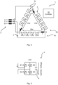
Fig 1 is a schematic circuit diagram of an embodiment of an MMC in double-wye configuration, in accordance with the present invention. -
Fig 2 is a schematic circuit diagram of an embodiment of an MMC in delta configuration, in accordance with the present invention. -
Fig 3 is a schematic circuit diagram of an embodiment of a bipolar MMC cell, in accordance with the present invention. -
Fig 4 is a schematic flow chart of an embodiment of a method of the present invention. - Embodiments will now be described more fully hereinafter with reference to the accompanying drawings, in which certain embodiments are shown. However, other embodiments in many different forms are possible within the scope of the present disclosure. Rather, the following embodiments are provided by way of example so that this disclosure will be thorough and complete, and will fully convey the scope of the disclosure to those skilled in the art. Like numbers refer to like elements throughout the description.
- The following description is focused on a Railway Intertie MMC (3- phase to 1- phase direct converter (see
figure 1 ). But embodiments of the invention can easily be applied to other topologies such as for example: - Statcom in MMC delta topology (see
figure 2 ). - Statcom in MMC star and/or double star topology.
- 3- phase to 3- phase MMC in direct and/or indirect topology (e.g. for pumped hydro applications).
- HVDC applications.
-
Figure 1 illustrates an embodiment of a 3-phase to 1-phase power converter 1 in double-wye (Y, star) configuration, e.g. in a railway intertie. Theconverter 1 is connected to and between twopower grids 5, typically via respective transformers, afirst power grid 5a which is here a 3-phase alternating current (AC) grid and asecond power grid 5b which is here a single-phase AC grid e.g. for railway electrification. In some embodiments, a reactor may be used instead of transformer on the single-phase side, e.g. when feeding into acatenary wire grid 5b (e.g. 15 kV), while a transformer may be preferred on the single-phase side when feeding into arailway grid 5b (e.g. no kV). TheMMC 1 comprises a plurality of phases 2, here afirst phase 2a, asecond phase 2b and athird phase 2c. Each phase 2 comprises at least onephase leg 3, here afirst phase leg 3a and asecond phase leg 3b. Eachphase leg 3 comprises a plurality of series connected (also called cascaded or chain-linked)converter cells 4, as well as a phase leg reactor L. Acontrol arrangement 10 may be comprised in theconverter 1 for controlling the same, e.g. for performing an embodiment of the method of the present invention, as well as for setting references and sending firing pulses etc. Thecontrol arrangement 10 may e.g. comprise a central network controller as well as a local control unit for eachcell 4. -
Figure 2 illustrates an embodiment of aSTATCOM 1 in delta (Δ) configuration. Theconverter 1 is connected to apower grid 5, here a 3-phase AC grid, typically with phase reactors L series connected in eachleg 3 in the delta configuration as shown in the figure, with line reactors (e.g. as shown between U and i1, V and i2, and Wand i3, in the figure, being optional). As in the embodiment offigure 1 , thepower converter 1 comprises a plurality of phases 2, here afirst phase 2a, asecond phase 2b and athird phase 2c. Each phase 2 comprises aphase leg 3. Eachphase leg 3 comprises a plurality of series connected (also called cascaded or chain-linked)converter cells 4. Again, acontrol arrangement 10 may be comprised in theconverter 1 for controlling the same, e.g. for performing an embodiment of the method of the present invention, as well as for setting references and sending firing pulses etc. Thecontrol arrangement 10 may e.g. comprise a central network controller as well as a local control unit for eachcell 4. -
Figure 3 illustrates an embodiment of aconverter cell 4. Thecell 4 comprises anenergy storage 6, e.g. in the form of a capacitor arrangement comprising at least one capacitor. Thecell 4 also comprises a plurality of semiconductor switches S forming e.g. a half-bridge (also called monopolar) topology or a full-bridge (also called H-bridge or bipolar) topology. In the embodiment offigure 3 , four semiconductor switches S1-S4 form a full-bridge topology. As indicated by the arrow by theenergy storage 6, a cell direct current (DC) voltage is present over theenergy storage 6 when thecell 4 is in use. - The nominal DC voltage of a phase leg 3 (i.e. the sum of all
individual cell 4 DC voltages of the phase leg) is chosen in such a way that theconverter 1 is able to run atmaximum grid 5 voltage, e.g. maximum specifiedgrid 5a voltage on the 3-phase side and simultaneouslymaximum grid 5b voltage on the 1-phase side for a railway intertie. Apart from that, some control margin is considered in the nominal DC voltage. - In accordance with the present invention, during grid failure and the resulting lower grid voltage, the required DC voltage of a phase leg is kept lower than in normal operation. At the time instant of the fault entry, the DC voltage may be reduced by a certain amount (e.g. by 10%).
- Normally the active power is controlled on the 1-
phase 5b side, that means that depending on the sign of the active power, the 1-phase side is injecting or withdrawing energy from theconverter 1. The total stored converter energy has to be maintained at a constant value, that means that the average of all cell DC voltages has to be controlled to a constant value (nominal cell DC voltage). This is done by a DC voltage controller, typically comprised in thecontrol arrangement 10 of theconverter 1, whose output is the active current reference for the 3- phase side current controller. To reduce the DC voltage during a fault in apower grid 5 in accordance with the present invention, e.g. the first orsecond power grids phase power grid 5b, offigure 1 , the reference value to the DC voltage controller is reduced accordingly (e.g. from 1 pu to O.9 pu, i.e. by 10%). - During the whole fault, the DC voltage will be kept at the reduced value. At the time instant when the grid voltage recovers, the DC voltage will raise again fast. The difference is now that due to the earlier reduction in DC voltage, the cell DC voltages do not hit the overvoltage limit and the
converter 1 stays in operation. - The same strategy may be applied for faults on the 3-
phase grid 5a side, or anyother power grid 5 side of an MMC. -
Figure 4 illustrates an embodiment of a method of the present invention. The method is for controlling anMMC 1 during a fault in apower grid 5 to which the MMC is connected. The MMC comprises a plurality of phases 2, each phase comprising at least onephase leg 3. Each phase leg comprises a plurality of series connectedconverter cells 4. The method comprises determining M1 that a fault has occurred in thepower grid 5, said fault including a reduced voltage in the power grid. The method also comprises, for eachphase leg 3 of the MMC, reducing M2 the DC voltage of the phase leg by a predetermined amount from a nominal DC voltage to a reduced DC voltage, the DC voltage being the sum of all respective voltages over anenergy storage 6 of eachcell 4 of the phase leg. The DC voltage may be reduced e.g. immediately (in a single step), stepwise, by ramping and/or with a delay of a predetermined time period. The method also comprises determining M3 that the fault has been cleared, whereby the voltage in thepower grid 5 is returned to nominal. The method also comprises, for each of thephase legs 3 of the MMC, increasing M4 the DC voltage back to the nominal DC voltage. The DC voltage may be increased e.g. immediately (in a single step), stepwise, by ramping and/or with a delay of a predetermined time period. - In some embodiments of the present invention, the predetermined amount with which the DC voltage is reduced is within the range of 5-20%, e.g. about 10%, of the nominal DC voltage.
- In some embodiments of the present invention, the reducing M2 of the DC voltage includes updating a voltage reference for the
phase leg 3, e.g. by a DC voltage controller of acontrol arrangement 10 of theconverter 1. - In some embodiments of the present invention, the
MMC 1 in in double-wye or delta configuration, e.g. as illustrated infigure 1 or2 . However, embodiments of the present invention may also be used with any other MMC topology, e.g. (single) wye. - In some embodiments of the present invention, the MMC (1) is configured for a railway intertie. However, a railway intertie is only an example and embodiments of the present invention may be useful also for any other converter application, e.g. STATCOM in delta topology (see
figure 2 ), STATCOM in wye (star) and/or double wye (star) topology, 3- phase to 3-phase MMC in direct and/or indirect topology (e.g. for pumped hydro applications), or HVDC applications. - Embodiments of the method of the present invention may be performed by a control arrangement to of the
MMC 1, which control arrangement comprises processing circuitry associated with a data storage. The processing circuitry may be equipped with one or more processing units CPU in the form of microprocessor(s) executing appropriate software stored in associated memory for procuring required functionality. However, other suitable devices with computing capabilities could be comprised in the processor, e.g. an application specific integrated circuit (ASIC), a field programmable gate array (FPGA), a complex programmable logic device (CPLD), etc., in order to control theMMC 1 and perform embodiments of the method of the present disclosure, while executing appropriate software, e.g. stored in a suitable data storage, such as a RAM, a Flash memory or a hard disk, or in the processing circuitry itself ( as e.g. in case of an FPGA). - Embodiments of the present invention may be conveniently implemented using one or more conventional general purpose or specialized digital computer, computing device, machine, or microprocessor, including one or more processors, memory and/or computer readable storage media programmed according to the teachings of the present disclosure. Appropriate software coding can readily be prepared by skilled programmers based on the teachings of the present disclosure, as will be apparent to those skilled in the software art.
- In some embodiments, the present invention includes a computer program product which is a non-transitory storage medium or computer readable medium (media) having instructions stored thereon/in which can be used to program a computer to perform any of the methods/processes of the present invention. Examples of the storage medium can include, but is not limited to, any type of disk including floppy disks, optical discs, DVD, CD-ROMs, microdrive, and magneto-optical disks, ROMs, RAMs, EPROMs, EEPROMs, DRAMs, VRAMs, flash memory devices, magnetic or optical cards, nanosystems (including molecular memory ICs), FPGA or any type of media or device suitable for storing instructions and/or data.
- The present disclosure has mainly been described above with reference to a few embodiments. However, as is readily appreciated by a person skilled in the art, other embodiments than the ones disclosed above are equally possible within the scope of the present disclosure, as defined by the appended claims.
Claims (7)
- A method of controlling a Modular Multilevel Converter, MMC, (1) for fault ride through during a fault in an AC power grid (5) to which the MMC is directly connected, the MMC comprising a plurality of phases (2), each phase comprising at least one phase leg (3), wherein each phase leg comprises a plurality of series connected converter cells (4), the method comprising:determining (M1) that a fault has occurred in the power grid (5), said fault including a reduced voltage in the power grid;for each phase leg (3) of the MMC, reducing (M2) the DC voltage of the phase leg by a predetermined amount from a nominal DC voltage to a reduced DC voltage, the DC voltage being the sum of all respective voltages over an energy storage (6) of each cell (4) of the phase leg;determining (M3) that the fault has been cleared;for each of the phase legs (3) of the MMC, increasing (M4) the DC voltage back to the nominal DC voltage.
- The method of claim 1, wherein the predetermined amount is within the range of 5-20% of the nominal DC voltage.
- The method of any preceding claim, wherein the reducing (M2) includes updating a voltage reference for the phase leg (3).
- The method of any preceding claim, wherein the MMC (1) in in double-wye or delta configuration.
- The method of any preceding claim, wherein the MMC (1) is configured for a railway intertie.
- A computer program product comprising computer-executable components for causing a control arrangement (10) of a Modular Multilevel Converter, MMC, (1) to perform the method of any preceding claim when the computer-executable components are run on processing circuitry comprised in the control arrangement.
- A control arrangement (10) for controlling a Modular Multilevel Converter, MMC, (1) for fault ride through during a fault in an AC power grid (5) to which the MMC is directly connected, the MMC comprising a plurality of phases (2), each phase comprising at least one phase leg (3), wherein each phase leg comprises a plurality of series connected converter cells (4), the control arrangement comprising:processing circuitry; anddata storage storing instructions executable by said processing circuitry whereby said control arrangement is operative to:determine that a fault has occurred in the power grid (5), said fault including a reduced voltage in the power grid;for each phase leg (3) of the MMC, reduce the DC voltage of the phase leg by a predetermined amount from a nominal DC voltage to a reduced DC voltage, the DC voltage being the sum of all respective voltages over an energy storage (6) of each cell (4) of the phase leg;determine that the fault has been cleared;for each of the phase legs (3) of the MMC, increase the DC voltage back to the nominal DC voltage.
Applications Claiming Priority (1)
| Application Number | Priority Date | Filing Date | Title |
|---|---|---|---|
| PCT/EP2017/065240 WO2018233824A1 (en) | 2017-06-21 | 2017-06-21 | CONTROL OF MMC DURING A BREAK |
Publications (2)
| Publication Number | Publication Date |
|---|---|
| EP3642947A1 EP3642947A1 (en) | 2020-04-29 |
| EP3642947B1 true EP3642947B1 (en) | 2023-10-11 |
Family
ID=59101461
Family Applications (1)
| Application Number | Title | Priority Date | Filing Date |
|---|---|---|---|
| EP17732093.4A Active EP3642947B1 (en) | 2017-06-21 | 2017-06-21 | Control of mmc during fault |
Country Status (4)
| Country | Link |
|---|---|
| US (1) | US10840822B2 (en) |
| EP (1) | EP3642947B1 (en) |
| CN (1) | CN110809852B (en) |
| WO (1) | WO2018233824A1 (en) |
Families Citing this family (5)
| Publication number | Priority date | Publication date | Assignee | Title |
|---|---|---|---|---|
| CN110771019B (en) * | 2017-06-21 | 2021-10-19 | Abb电网瑞士股份公司 | Model-Based Current Control for Three-Phase-Single-Phase Power Converters |
| CN109484254B (en) * | 2018-12-04 | 2021-09-14 | 武汉大学 | Power supply topological structure for passing neutral section of high-speed railway system and control method |
| EP4147345B1 (en) * | 2020-07-10 | 2023-10-04 | Hitachi Energy Switzerland AG | Control of a modular multilevel converter of a full bridge or mixed arm type in case of a dc line disturbance |
| CN112072940B (en) * | 2020-09-08 | 2022-02-18 | 南京南瑞继保电气有限公司 | Active modular converter chain, converter control method and device and electronic equipment |
| JP7675620B2 (en) * | 2021-11-01 | 2025-05-13 | 株式会社東芝 | Power Conversion Equipment |
Citations (1)
| Publication number | Priority date | Publication date | Assignee | Title |
|---|---|---|---|---|
| CN105762824A (en) * | 2016-03-10 | 2016-07-13 | 南京南瑞继保电气有限公司 | Hybrid direct current power transmission system control method and device |
Family Cites Families (7)
| Publication number | Priority date | Publication date | Assignee | Title |
|---|---|---|---|---|
| EP2443732B1 (en) * | 2009-06-18 | 2013-08-14 | ABB Technology AG | An arrangement for exchanging power |
| WO2011113471A1 (en) * | 2010-03-15 | 2011-09-22 | Areva T&D Uk Ltd | Static var compensator with multilevel converter |
| EP2595265A1 (en) * | 2011-11-17 | 2013-05-22 | Siemens Aktiengesellschaft | Power supply system of a marine vessel |
| IN2014KN01145A (en) * | 2011-12-15 | 2015-10-16 | Siemens Ag | |
| CN103248255B (en) * | 2013-05-24 | 2014-12-31 | 哈尔滨工业大学 | Tri-phase modular multi-level converter and fault-tolerate detecting method for IGBT (insulated gate bipolar translator) open circuit fault in sub-modules thereof |
| CN104167912B (en) * | 2014-08-14 | 2016-08-31 | 华中科技大学 | A kind of MMC possessing zero DC voltage fault ride-through capacity and method for designing thereof |
| EP3391522B1 (en) * | 2015-12-18 | 2019-10-16 | ABB Schweiz AG | Voltage balancing in a modular multilevel converter having delta configuration |
-
2017
- 2017-06-21 EP EP17732093.4A patent/EP3642947B1/en active Active
- 2017-06-21 US US16/624,187 patent/US10840822B2/en active Active
- 2017-06-21 WO PCT/EP2017/065240 patent/WO2018233824A1/en not_active Ceased
- 2017-06-21 CN CN201780092376.1A patent/CN110809852B/en active Active
Patent Citations (2)
| Publication number | Priority date | Publication date | Assignee | Title |
|---|---|---|---|---|
| CN105762824A (en) * | 2016-03-10 | 2016-07-13 | 南京南瑞继保电气有限公司 | Hybrid direct current power transmission system control method and device |
| US20190052087A1 (en) * | 2016-03-10 | 2019-02-14 | Nr Electric Co., Ltd. | Method And Apparatus For Controlling Hybrid Direct-Current Transmission System |
Also Published As
| Publication number | Publication date |
|---|---|
| US20200177098A1 (en) | 2020-06-04 |
| CN110809852A (en) | 2020-02-18 |
| WO2018233824A1 (en) | 2018-12-27 |
| EP3642947A1 (en) | 2020-04-29 |
| US10840822B2 (en) | 2020-11-17 |
| CN110809852B (en) | 2022-05-24 |
Similar Documents
| Publication | Publication Date | Title |
|---|---|---|
| US11201565B2 (en) | Conversion circuit, control method, and power supply device | |
| US10651755B2 (en) | Standby and charging of modular multilevel converters | |
| EP3642947B1 (en) | Control of mmc during fault | |
| CN101297469B (en) | A transmission system and a method for control thereof | |
| US9048691B2 (en) | Converters | |
| EP3278435B1 (en) | Voltage source converters provided with dc fault control | |
| JP6261491B2 (en) | Power converter | |
| JP6529676B2 (en) | Active discharge of a modular multilevel converter | |
| EP2719066B1 (en) | Methods for de-energizing a chain-link converter, controller, computer programs and computer program products | |
| US10110110B2 (en) | Power conversion device | |
| US20190068081A1 (en) | Converter | |
| EP3729631B1 (en) | Mmc phase leg and method for control thereof | |
| WO2019007479A1 (en) | Power converter voltage balancing | |
| CN108604797B (en) | Multilevel power converter and method for controlling a multilevel power converter | |
| EP3714538B1 (en) | Control of a power converter | |
| CN112534695B (en) | Methods for controlling MMC | |
| CN106899033A (en) | The electricity generation system and its control method of many converter wind turbines | |
| EP4550604A1 (en) | An energy storage system embedded in a power network |
Legal Events
| Date | Code | Title | Description |
|---|---|---|---|
| STAA | Information on the status of an ep patent application or granted ep patent |
Free format text: STATUS: UNKNOWN |
|
| STAA | Information on the status of an ep patent application or granted ep patent |
Free format text: STATUS: THE INTERNATIONAL PUBLICATION HAS BEEN MADE |
|
| PUAI | Public reference made under article 153(3) epc to a published international application that has entered the european phase |
Free format text: ORIGINAL CODE: 0009012 |
|
| STAA | Information on the status of an ep patent application or granted ep patent |
Free format text: STATUS: REQUEST FOR EXAMINATION WAS MADE |
|
| 17P | Request for examination filed |
Effective date: 20191216 |
|
| AK | Designated contracting states |
Kind code of ref document: A1 Designated state(s): AL AT BE BG CH CY CZ DE DK EE ES FI FR GB GR HR HU IE IS IT LI LT LU LV MC MK MT NL NO PL PT RO RS SE SI SK SM TR |
|
| AX | Request for extension of the european patent |
Extension state: BA ME |
|
| RIN1 | Information on inventor provided before grant (corrected) |
Inventor name: BANCEANU, COSMIN Inventor name: BUCHMANN, BEAT |
|
| DAV | Request for validation of the european patent (deleted) | ||
| DAX | Request for extension of the european patent (deleted) | ||
| STAA | Information on the status of an ep patent application or granted ep patent |
Free format text: STATUS: EXAMINATION IS IN PROGRESS |
|
| 17Q | First examination report despatched |
Effective date: 20201029 |
|
| RAP1 | Party data changed (applicant data changed or rights of an application transferred) |
Owner name: ABB POWER GRIDS SWITZERLAND AG |
|
| RIC1 | Information provided on ipc code assigned before grant |
Ipc: H02M 7/483 20070101ALI20211203BHEP Ipc: H02M 1/32 20070101AFI20211203BHEP |
|
| GRAP | Despatch of communication of intention to grant a patent |
Free format text: ORIGINAL CODE: EPIDOSNIGR1 |
|
| STAA | Information on the status of an ep patent application or granted ep patent |
Free format text: STATUS: GRANT OF PATENT IS INTENDED |
|
| RAP3 | Party data changed (applicant data changed or rights of an application transferred) |
Owner name: HITACHI ENERGY SWITZERLAND AG |
|
| INTG | Intention to grant announced |
Effective date: 20220114 |
|
| GRAJ | Information related to disapproval of communication of intention to grant by the applicant or resumption of examination proceedings by the epo deleted |
Free format text: ORIGINAL CODE: EPIDOSDIGR1 |
|
| STAA | Information on the status of an ep patent application or granted ep patent |
Free format text: STATUS: EXAMINATION IS IN PROGRESS |
|
| INTC | Intention to grant announced (deleted) | ||
| GRAP | Despatch of communication of intention to grant a patent |
Free format text: ORIGINAL CODE: EPIDOSNIGR1 |
|
| STAA | Information on the status of an ep patent application or granted ep patent |
Free format text: STATUS: GRANT OF PATENT IS INTENDED |
|
| INTG | Intention to grant announced |
Effective date: 20230510 |
|
| P01 | Opt-out of the competence of the unified patent court (upc) registered |
Effective date: 20230527 |
|
| GRAS | Grant fee paid |
Free format text: ORIGINAL CODE: EPIDOSNIGR3 |
|
| GRAA | (expected) grant |
Free format text: ORIGINAL CODE: 0009210 |
|
| STAA | Information on the status of an ep patent application or granted ep patent |
Free format text: STATUS: THE PATENT HAS BEEN GRANTED |
|
| AK | Designated contracting states |
Kind code of ref document: B1 Designated state(s): AL AT BE BG CH CY CZ DE DK EE ES FI FR GB GR HR HU IE IS IT LI LT LU LV MC MK MT NL NO PL PT RO RS SE SI SK SM TR |
|
| REG | Reference to a national code |
Ref country code: GB Ref legal event code: FG4D |
|
| REG | Reference to a national code |
Ref country code: CH Ref legal event code: EP |
|
| REG | Reference to a national code |
Ref country code: DE Ref legal event code: R096 Ref document number: 602017075176 Country of ref document: DE |
|
| REG | Reference to a national code |
Ref country code: IE Ref legal event code: FG4D |
|
| REG | Reference to a national code |
Ref country code: SE Ref legal event code: TRGR |
|
| RAP2 | Party data changed (patent owner data changed or rights of a patent transferred) |
Owner name: HITACHI ENERGY LTD |
|
| REG | Reference to a national code |
Ref country code: NO Ref legal event code: T2 Effective date: 20231011 |
|
| REG | Reference to a national code |
Ref country code: LT Ref legal event code: MG9D Ref country code: NO Ref legal event code: CHAD Owner name: HITACHI ENERGY LTD, CH |
|
| REG | Reference to a national code |
Ref country code: NL Ref legal event code: MP Effective date: 20231011 |
|
| RAP4 | Party data changed (patent owner data changed or rights of a patent transferred) |
Owner name: HITACHI ENERGY SWITZERLAND AG |
|
| RAP2 | Party data changed (patent owner data changed or rights of a patent transferred) |
Owner name: HITACHI ENERGY LTD |
|
| REG | Reference to a national code |
Ref country code: AT Ref legal event code: MK05 Ref document number: 1621228 Country of ref document: AT Kind code of ref document: T Effective date: 20231011 |
|
| PG25 | Lapsed in a contracting state [announced via postgrant information from national office to epo] |
Ref country code: NL Free format text: LAPSE BECAUSE OF FAILURE TO SUBMIT A TRANSLATION OF THE DESCRIPTION OR TO PAY THE FEE WITHIN THE PRESCRIBED TIME-LIMIT Effective date: 20231011 |
|
| REG | Reference to a national code |
Ref country code: DE Ref legal event code: R081 Ref document number: 602017075176 Country of ref document: DE Owner name: HITACHI ENERGY LTD, CH Free format text: FORMER OWNER: HITACHI ENERGY SWITZERLAND AG, BADEN, CH |
|
| PG25 | Lapsed in a contracting state [announced via postgrant information from national office to epo] |
Ref country code: GR Free format text: LAPSE BECAUSE OF FAILURE TO SUBMIT A TRANSLATION OF THE DESCRIPTION OR TO PAY THE FEE WITHIN THE PRESCRIBED TIME-LIMIT Effective date: 20240112 |
|
| PG25 | Lapsed in a contracting state [announced via postgrant information from national office to epo] |
Ref country code: IS Free format text: LAPSE BECAUSE OF FAILURE TO SUBMIT A TRANSLATION OF THE DESCRIPTION OR TO PAY THE FEE WITHIN THE PRESCRIBED TIME-LIMIT Effective date: 20240211 |
|
| PG25 | Lapsed in a contracting state [announced via postgrant information from national office to epo] |
Ref country code: LT Free format text: LAPSE BECAUSE OF FAILURE TO SUBMIT A TRANSLATION OF THE DESCRIPTION OR TO PAY THE FEE WITHIN THE PRESCRIBED TIME-LIMIT Effective date: 20231011 |
|
| PG25 | Lapsed in a contracting state [announced via postgrant information from national office to epo] |
Ref country code: AT Free format text: LAPSE BECAUSE OF FAILURE TO SUBMIT A TRANSLATION OF THE DESCRIPTION OR TO PAY THE FEE WITHIN THE PRESCRIBED TIME-LIMIT Effective date: 20231011 |
|
| PG25 | Lapsed in a contracting state [announced via postgrant information from national office to epo] |
Ref country code: ES Free format text: LAPSE BECAUSE OF FAILURE TO SUBMIT A TRANSLATION OF THE DESCRIPTION OR TO PAY THE FEE WITHIN THE PRESCRIBED TIME-LIMIT Effective date: 20231011 |
|
| PG25 | Lapsed in a contracting state [announced via postgrant information from national office to epo] |
Ref country code: LT Free format text: LAPSE BECAUSE OF FAILURE TO SUBMIT A TRANSLATION OF THE DESCRIPTION OR TO PAY THE FEE WITHIN THE PRESCRIBED TIME-LIMIT Effective date: 20231011 Ref country code: IS Free format text: LAPSE BECAUSE OF FAILURE TO SUBMIT A TRANSLATION OF THE DESCRIPTION OR TO PAY THE FEE WITHIN THE PRESCRIBED TIME-LIMIT Effective date: 20240211 Ref country code: GR Free format text: LAPSE BECAUSE OF FAILURE TO SUBMIT A TRANSLATION OF THE DESCRIPTION OR TO PAY THE FEE WITHIN THE PRESCRIBED TIME-LIMIT Effective date: 20240112 Ref country code: ES Free format text: LAPSE BECAUSE OF FAILURE TO SUBMIT A TRANSLATION OF THE DESCRIPTION OR TO PAY THE FEE WITHIN THE PRESCRIBED TIME-LIMIT Effective date: 20231011 Ref country code: BG Free format text: LAPSE BECAUSE OF FAILURE TO SUBMIT A TRANSLATION OF THE DESCRIPTION OR TO PAY THE FEE WITHIN THE PRESCRIBED TIME-LIMIT Effective date: 20240111 Ref country code: AT Free format text: LAPSE BECAUSE OF FAILURE TO SUBMIT A TRANSLATION OF THE DESCRIPTION OR TO PAY THE FEE WITHIN THE PRESCRIBED TIME-LIMIT Effective date: 20231011 Ref country code: PT Free format text: LAPSE BECAUSE OF FAILURE TO SUBMIT A TRANSLATION OF THE DESCRIPTION OR TO PAY THE FEE WITHIN THE PRESCRIBED TIME-LIMIT Effective date: 20240212 |
|
| PG25 | Lapsed in a contracting state [announced via postgrant information from national office to epo] |
Ref country code: RS Free format text: LAPSE BECAUSE OF FAILURE TO SUBMIT A TRANSLATION OF THE DESCRIPTION OR TO PAY THE FEE WITHIN THE PRESCRIBED TIME-LIMIT Effective date: 20231011 Ref country code: PL Free format text: LAPSE BECAUSE OF FAILURE TO SUBMIT A TRANSLATION OF THE DESCRIPTION OR TO PAY THE FEE WITHIN THE PRESCRIBED TIME-LIMIT Effective date: 20231011 Ref country code: LV Free format text: LAPSE BECAUSE OF FAILURE TO SUBMIT A TRANSLATION OF THE DESCRIPTION OR TO PAY THE FEE WITHIN THE PRESCRIBED TIME-LIMIT Effective date: 20231011 Ref country code: HR Free format text: LAPSE BECAUSE OF FAILURE TO SUBMIT A TRANSLATION OF THE DESCRIPTION OR TO PAY THE FEE WITHIN THE PRESCRIBED TIME-LIMIT Effective date: 20231011 |
|
| PG25 | Lapsed in a contracting state [announced via postgrant information from national office to epo] |
Ref country code: DK Free format text: LAPSE BECAUSE OF FAILURE TO SUBMIT A TRANSLATION OF THE DESCRIPTION OR TO PAY THE FEE WITHIN THE PRESCRIBED TIME-LIMIT Effective date: 20231011 |
|
| REG | Reference to a national code |
Ref country code: DE Ref legal event code: R097 Ref document number: 602017075176 Country of ref document: DE |
|
| PG25 | Lapsed in a contracting state [announced via postgrant information from national office to epo] |
Ref country code: CZ Free format text: LAPSE BECAUSE OF FAILURE TO SUBMIT A TRANSLATION OF THE DESCRIPTION OR TO PAY THE FEE WITHIN THE PRESCRIBED TIME-LIMIT Effective date: 20231011 |
|
| PG25 | Lapsed in a contracting state [announced via postgrant information from national office to epo] |
Ref country code: SK Free format text: LAPSE BECAUSE OF FAILURE TO SUBMIT A TRANSLATION OF THE DESCRIPTION OR TO PAY THE FEE WITHIN THE PRESCRIBED TIME-LIMIT Effective date: 20231011 |
|
| PG25 | Lapsed in a contracting state [announced via postgrant information from national office to epo] |
Ref country code: SM Free format text: LAPSE BECAUSE OF FAILURE TO SUBMIT A TRANSLATION OF THE DESCRIPTION OR TO PAY THE FEE WITHIN THE PRESCRIBED TIME-LIMIT Effective date: 20231011 Ref country code: SK Free format text: LAPSE BECAUSE OF FAILURE TO SUBMIT A TRANSLATION OF THE DESCRIPTION OR TO PAY THE FEE WITHIN THE PRESCRIBED TIME-LIMIT Effective date: 20231011 Ref country code: RO Free format text: LAPSE BECAUSE OF FAILURE TO SUBMIT A TRANSLATION OF THE DESCRIPTION OR TO PAY THE FEE WITHIN THE PRESCRIBED TIME-LIMIT Effective date: 20231011 Ref country code: IT Free format text: LAPSE BECAUSE OF FAILURE TO SUBMIT A TRANSLATION OF THE DESCRIPTION OR TO PAY THE FEE WITHIN THE PRESCRIBED TIME-LIMIT Effective date: 20231011 Ref country code: EE Free format text: LAPSE BECAUSE OF FAILURE TO SUBMIT A TRANSLATION OF THE DESCRIPTION OR TO PAY THE FEE WITHIN THE PRESCRIBED TIME-LIMIT Effective date: 20231011 Ref country code: DK Free format text: LAPSE BECAUSE OF FAILURE TO SUBMIT A TRANSLATION OF THE DESCRIPTION OR TO PAY THE FEE WITHIN THE PRESCRIBED TIME-LIMIT Effective date: 20231011 Ref country code: CZ Free format text: LAPSE BECAUSE OF FAILURE TO SUBMIT A TRANSLATION OF THE DESCRIPTION OR TO PAY THE FEE WITHIN THE PRESCRIBED TIME-LIMIT Effective date: 20231011 |
|
| PLBE | No opposition filed within time limit |
Free format text: ORIGINAL CODE: 0009261 |
|
| STAA | Information on the status of an ep patent application or granted ep patent |
Free format text: STATUS: NO OPPOSITION FILED WITHIN TIME LIMIT |
|
| 26N | No opposition filed |
Effective date: 20240712 |
|
| PG25 | Lapsed in a contracting state [announced via postgrant information from national office to epo] |
Ref country code: SI Free format text: LAPSE BECAUSE OF FAILURE TO SUBMIT A TRANSLATION OF THE DESCRIPTION OR TO PAY THE FEE WITHIN THE PRESCRIBED TIME-LIMIT Effective date: 20231011 |
|
| PG25 | Lapsed in a contracting state [announced via postgrant information from national office to epo] |
Ref country code: SI Free format text: LAPSE BECAUSE OF FAILURE TO SUBMIT A TRANSLATION OF THE DESCRIPTION OR TO PAY THE FEE WITHIN THE PRESCRIBED TIME-LIMIT Effective date: 20231011 |
|
| PG25 | Lapsed in a contracting state [announced via postgrant information from national office to epo] |
Ref country code: MC Free format text: LAPSE BECAUSE OF FAILURE TO SUBMIT A TRANSLATION OF THE DESCRIPTION OR TO PAY THE FEE WITHIN THE PRESCRIBED TIME-LIMIT Effective date: 20231011 |
|
| PG25 | Lapsed in a contracting state [announced via postgrant information from national office to epo] |
Ref country code: LU Free format text: LAPSE BECAUSE OF NON-PAYMENT OF DUE FEES Effective date: 20240621 |
|
| GBPC | Gb: european patent ceased through non-payment of renewal fee |
Effective date: 20240621 |
|
| PG25 | Lapsed in a contracting state [announced via postgrant information from national office to epo] |
Ref country code: IE Free format text: LAPSE BECAUSE OF NON-PAYMENT OF DUE FEES Effective date: 20240621 |
|
| PG25 | Lapsed in a contracting state [announced via postgrant information from national office to epo] |
Ref country code: BE Free format text: LAPSE BECAUSE OF NON-PAYMENT OF DUE FEES Effective date: 20240630 |
|
| PG25 | Lapsed in a contracting state [announced via postgrant information from national office to epo] |
Ref country code: FR Free format text: LAPSE BECAUSE OF NON-PAYMENT OF DUE FEES Effective date: 20240630 |
|
| PG25 | Lapsed in a contracting state [announced via postgrant information from national office to epo] |
Ref country code: GB Free format text: LAPSE BECAUSE OF NON-PAYMENT OF DUE FEES Effective date: 20240621 |
|
| REG | Reference to a national code |
Ref country code: BE Ref legal event code: MM Effective date: 20240630 |
|
| REG | Reference to a national code |
Ref country code: DE Ref legal event code: R082 Ref document number: 602017075176 Country of ref document: DE Representative=s name: DENNEMEYER & ASSOCIATES RECHTSANWALTSGESELLSCH, DE |
|
| PGFP | Annual fee paid to national office [announced via postgrant information from national office to epo] |
Ref country code: DE Payment date: 20250618 Year of fee payment: 9 |
|
| PGFP | Annual fee paid to national office [announced via postgrant information from national office to epo] |
Ref country code: NO Payment date: 20250624 Year of fee payment: 9 |
|
| PGFP | Annual fee paid to national office [announced via postgrant information from national office to epo] |
Ref country code: SE Payment date: 20250618 Year of fee payment: 9 |
|
| PG25 | Lapsed in a contracting state [announced via postgrant information from national office to epo] |
Ref country code: FI Free format text: LAPSE BECAUSE OF FAILURE TO SUBMIT A TRANSLATION OF THE DESCRIPTION OR TO PAY THE FEE WITHIN THE PRESCRIBED TIME-LIMIT Effective date: 20231011 |
|
| PGFP | Annual fee paid to national office [announced via postgrant information from national office to epo] |
Ref country code: CH Payment date: 20250701 Year of fee payment: 9 |
|
| PG25 | Lapsed in a contracting state [announced via postgrant information from national office to epo] |
Ref country code: CY Free format text: LAPSE BECAUSE OF FAILURE TO SUBMIT A TRANSLATION OF THE DESCRIPTION OR TO PAY THE FEE WITHIN THE PRESCRIBED TIME-LIMIT; INVALID AB INITIO Effective date: 20170621 |
|
| PG25 | Lapsed in a contracting state [announced via postgrant information from national office to epo] |
Ref country code: HU Free format text: LAPSE BECAUSE OF FAILURE TO SUBMIT A TRANSLATION OF THE DESCRIPTION OR TO PAY THE FEE WITHIN THE PRESCRIBED TIME-LIMIT; INVALID AB INITIO Effective date: 20170621 |