EP3641949B1 - System and process for applying an adhesive to a moving web - Google Patents
System and process for applying an adhesive to a moving web Download PDFInfo
- Publication number
- EP3641949B1 EP3641949B1 EP17914951.3A EP17914951A EP3641949B1 EP 3641949 B1 EP3641949 B1 EP 3641949B1 EP 17914951 A EP17914951 A EP 17914951A EP 3641949 B1 EP3641949 B1 EP 3641949B1
- Authority
- EP
- European Patent Office
- Prior art keywords
- web
- adhesive
- nozzle
- moving
- contact
- Prior art date
- Legal status (The legal status is an assumption and is not a legal conclusion. Google has not performed a legal analysis and makes no representation as to the accuracy of the status listed.)
- Active
Links
Images


Classifications
-
- B—PERFORMING OPERATIONS; TRANSPORTING
- B05—SPRAYING OR ATOMISING IN GENERAL; APPLYING FLUENT MATERIALS TO SURFACES, IN GENERAL
- B05B—SPRAYING APPARATUS; ATOMISING APPARATUS; NOZZLES
- B05B13/00—Machines or plants for applying liquids or other fluent materials to surfaces of objects or other work by spraying, not covered by groups B05B1/00 - B05B11/00
- B05B13/02—Means for supporting work; Arrangement or mounting of spray heads; Adaptation or arrangement of means for feeding work
- B05B13/0221—Means for supporting work; Arrangement or mounting of spray heads; Adaptation or arrangement of means for feeding work characterised by the means for moving or conveying the objects or other work, e.g. conveyor belts
- B05B13/025—Means for supporting work; Arrangement or mounting of spray heads; Adaptation or arrangement of means for feeding work characterised by the means for moving or conveying the objects or other work, e.g. conveyor belts the objects or work being present in bulk
-
- B—PERFORMING OPERATIONS; TRANSPORTING
- B05—SPRAYING OR ATOMISING IN GENERAL; APPLYING FLUENT MATERIALS TO SURFACES, IN GENERAL
- B05B—SPRAYING APPARATUS; ATOMISING APPARATUS; NOZZLES
- B05B13/00—Machines or plants for applying liquids or other fluent materials to surfaces of objects or other work by spraying, not covered by groups B05B1/00 - B05B11/00
- B05B13/02—Means for supporting work; Arrangement or mounting of spray heads; Adaptation or arrangement of means for feeding work
-
- B—PERFORMING OPERATIONS; TRANSPORTING
- B05—SPRAYING OR ATOMISING IN GENERAL; APPLYING FLUENT MATERIALS TO SURFACES, IN GENERAL
- B05B—SPRAYING APPARATUS; ATOMISING APPARATUS; NOZZLES
- B05B13/00—Machines or plants for applying liquids or other fluent materials to surfaces of objects or other work by spraying, not covered by groups B05B1/00 - B05B11/00
- B05B13/02—Means for supporting work; Arrangement or mounting of spray heads; Adaptation or arrangement of means for feeding work
- B05B13/0278—Arrangement or mounting of spray heads
-
- B—PERFORMING OPERATIONS; TRANSPORTING
- B05—SPRAYING OR ATOMISING IN GENERAL; APPLYING FLUENT MATERIALS TO SURFACES, IN GENERAL
- B05B—SPRAYING APPARATUS; ATOMISING APPARATUS; NOZZLES
- B05B9/00—Spraying apparatus for discharge of liquids or other fluent material, without essentially mixing with gas or vapour
- B05B9/03—Spraying apparatus for discharge of liquids or other fluent material, without essentially mixing with gas or vapour characterised by means for supplying liquid or other fluent material
-
- B—PERFORMING OPERATIONS; TRANSPORTING
- B05—SPRAYING OR ATOMISING IN GENERAL; APPLYING FLUENT MATERIALS TO SURFACES, IN GENERAL
- B05C—APPARATUS FOR APPLYING FLUENT MATERIALS TO SURFACES, IN GENERAL
- B05C11/00—Component parts, details or accessories not specifically provided for in groups B05C1/00 - B05C9/00
- B05C11/10—Storage, supply or control of liquid or other fluent material; Recovery of excess liquid or other fluent material
- B05C11/1002—Means for controlling supply, i.e. flow or pressure, of liquid or other fluent material to the applying apparatus, e.g. valves
- B05C11/1005—Means for controlling supply, i.e. flow or pressure, of liquid or other fluent material to the applying apparatus, e.g. valves responsive to condition of liquid or other fluent material already applied to the surface, e.g. coating thickness, weight or pattern
-
- B—PERFORMING OPERATIONS; TRANSPORTING
- B05—SPRAYING OR ATOMISING IN GENERAL; APPLYING FLUENT MATERIALS TO SURFACES, IN GENERAL
- B05C—APPARATUS FOR APPLYING FLUENT MATERIALS TO SURFACES, IN GENERAL
- B05C5/00—Apparatus in which liquid or other fluent material is projected, poured or allowed to flow on to the surface of the work
- B05C5/02—Apparatus in which liquid or other fluent material is projected, poured or allowed to flow on to the surface of the work the liquid or other fluent material being discharged through an outlet orifice by pressure, e.g. from an outlet device in contact or almost in contact, with the work
- B05C5/027—Coating heads with several outlets, e.g. aligned transversally to the moving direction of a web to be coated
- B05C5/0275—Coating heads with several outlets, e.g. aligned transversally to the moving direction of a web to be coated flow controlled, e.g. by a valve
- B05C5/0279—Coating heads with several outlets, e.g. aligned transversally to the moving direction of a web to be coated flow controlled, e.g. by a valve independently, e.g. individually, flow controlled
-
- B—PERFORMING OPERATIONS; TRANSPORTING
- B05—SPRAYING OR ATOMISING IN GENERAL; APPLYING FLUENT MATERIALS TO SURFACES, IN GENERAL
- B05D—PROCESSES FOR APPLYING FLUENT MATERIALS TO SURFACES, IN GENERAL
- B05D1/00—Processes for applying liquids or other fluent materials
- B05D1/02—Processes for applying liquids or other fluent materials performed by spraying
-
- B—PERFORMING OPERATIONS; TRANSPORTING
- B05—SPRAYING OR ATOMISING IN GENERAL; APPLYING FLUENT MATERIALS TO SURFACES, IN GENERAL
- B05D—PROCESSES FOR APPLYING FLUENT MATERIALS TO SURFACES, IN GENERAL
- B05D1/00—Processes for applying liquids or other fluent materials
- B05D1/26—Processes for applying liquids or other fluent materials performed by applying the liquid or other fluent material from an outlet device in contact with, or almost in contact with, the surface
- B05D1/265—Extrusion coatings
-
- B—PERFORMING OPERATIONS; TRANSPORTING
- B05—SPRAYING OR ATOMISING IN GENERAL; APPLYING FLUENT MATERIALS TO SURFACES, IN GENERAL
- B05D—PROCESSES FOR APPLYING FLUENT MATERIALS TO SURFACES, IN GENERAL
- B05D5/00—Processes for applying liquids or other fluent materials to surfaces to obtain special surface effects, finishes or structures
- B05D5/10—Processes for applying liquids or other fluent materials to surfaces to obtain special surface effects, finishes or structures to obtain an adhesive surface
-
- B—PERFORMING OPERATIONS; TRANSPORTING
- B05—SPRAYING OR ATOMISING IN GENERAL; APPLYING FLUENT MATERIALS TO SURFACES, IN GENERAL
- B05D—PROCESSES FOR APPLYING FLUENT MATERIALS TO SURFACES, IN GENERAL
- B05D7/00—Processes, other than flocking, specially adapted for applying liquids or other fluent materials to particular surfaces or for applying particular liquids or other fluent materials
- B05D7/02—Processes, other than flocking, specially adapted for applying liquids or other fluent materials to particular surfaces or for applying particular liquids or other fluent materials to macromolecular substances, e.g. rubber
- B05D7/04—Processes, other than flocking, specially adapted for applying liquids or other fluent materials to particular surfaces or for applying particular liquids or other fluent materials to macromolecular substances, e.g. rubber to surfaces of films or sheets
-
- B—PERFORMING OPERATIONS; TRANSPORTING
- B05—SPRAYING OR ATOMISING IN GENERAL; APPLYING FLUENT MATERIALS TO SURFACES, IN GENERAL
- B05B—SPRAYING APPARATUS; ATOMISING APPARATUS; NOZZLES
- B05B15/00—Details of spraying plant or spraying apparatus not otherwise provided for; Accessories
- B05B15/50—Arrangements for cleaning; Arrangements for preventing deposits, drying-out or blockage; Arrangements for detecting improper discharge caused by the presence of foreign matter
- B05B15/52—Arrangements for cleaning; Arrangements for preventing deposits, drying-out or blockage; Arrangements for detecting improper discharge caused by the presence of foreign matter for removal of clogging particles
-
- B—PERFORMING OPERATIONS; TRANSPORTING
- B05—SPRAYING OR ATOMISING IN GENERAL; APPLYING FLUENT MATERIALS TO SURFACES, IN GENERAL
- B05D—PROCESSES FOR APPLYING FLUENT MATERIALS TO SURFACES, IN GENERAL
- B05D2201/00—Polymeric substrate or laminate
- B05D2201/02—Polymeric substrate
-
- B—PERFORMING OPERATIONS; TRANSPORTING
- B05—SPRAYING OR ATOMISING IN GENERAL; APPLYING FLUENT MATERIALS TO SURFACES, IN GENERAL
- B05D—PROCESSES FOR APPLYING FLUENT MATERIALS TO SURFACES, IN GENERAL
- B05D2252/00—Sheets
- B05D2252/02—Sheets of indefinite length
Definitions
- Absorbent articles such as disposable diapers, training pants, adult incontinence articles and the like, generally include several different components which are adhesively bonded together.
- adhesive has been used to bond individual layers of the absorbent article, such as the outer cover and body side liner, together.
- Adhesive has also been used to bond discrete pieces, such as the fasteners and leg elastics, to the article.
- the adhesive has been sprayed or slot-coated on the continuous moving web which provides the absorbent articles.
- the sufficiency of the adhesive bond between the components of the absorbent article is generally dependent upon the amount of adhesive, the type of adhesive and the pattern of the adhesive.
- adhesive applicators as described above also have experienced problems with maintaining uniform flow through the adhesive head due to clogging and other issues. For instance, over time, adhesive heads can generate significant amounts of dust and lint. In addition, adhesive build up on the head can occur over time. Thus, adhesive applicators are typically periodically cleaned which can require downtime of the process.
- US 4371571 discloses fluid adhesive and similar applicator systems and methods.
- US 2013/0260031 discloses an adhesive agent applying apparatus.
- US 2029922 discloses an apparatus and method for uniting layers of material.
- US 2004/161531 discloses a process for applying glue, in particular glue of the hot-melt type.
- US 5614023 discloses a method of applying a liquid to a flexible substrate.
- the present disclosure is directed to a system and process for applying an adhesive to a moving web of material.
- the system and process of the present disclosure are capable of dramatically reducing the adhesive application length when the web of material is running at high speeds in comparison to conventional systems.
- the system and process of the present disclosure is also capable of providing better control of application of the adhesive.
- the system and process of the present disclosure can apply adhesives to moving webs in unique patterns that can result in improved bonding between two materials during the process.
- the adhesive control device can be configured to enable and disable flow of adhesive through the nozzle prior to the nozzle contacting a moving web of material.
- the adhesive control device can be configured to enable flow of adhesive through the nozzle prior to contact with the moving web and then to disable flow of an adhesive through the nozzle while the nozzle is in contact with the moving web of material. In this manner, lesser of amounts of adhesive can be applied to the web even at extremely fast speeds.
- the length of adhesive applied to the moving web can be minimized in relation to the amount of time the moving web is in contact with the nozzle.
- the web deflecting device can cause the moving web of material to contact the nozzle by moving the web and/or by moving the nozzle.
- the web deflecting device comprises a deflecting cam that moves the moving web of material periodically into contact with the nozzle.
- the deflecting cam can be attached to a rotating roll positioned adjacent to the moving web of material.
- the deflecting cam can project from the surface of the rotating roll. As the roll rotates, the deflecting cam contacts the web and pushes the web into contact with the nozzle.
- the rotating roll can be configured to rotate at a speed such that a web contacting surface on the deflecting cam moves at a speed that is faster than the speed at which the web of material is moving.
- the action of the web contacting the nozzle not only removes adhesive from the nozzle but also wipes the nozzle head in a manner that prevents the buildup of adhesive and prevents the buildup of lint and dust.
- the deflecting device causes the moving web of material to contact the nozzle in a manner such that the web forms a maximum exit angle with the nozzle.
- the maximum exit angle is from about 5° to about 30° in relation to a horizontal plane that is perpendicular to an exit port on the nozzle.
- the exit angle can constantly change from a minimum exit angle to a maximum exit angle as the deflecting device deflects the web.
- the deflecting device can be positioned downstream from the nozzle or can be positioned upstream from the nozzle. In one embodiment, the deflecting device contacts the moving web of material in a manner that causes the web of material to increase in tension during contact with the nozzle. Increasing the tension of the web can further improve application of the adhesive to the web. In one embodiment, the web conveying device moves the web of material at a speed of at least 400 m/min, such as at least about 450 m/min, such as at least about 500 m/min, such as at least about 550 m/min, such as even greater than about 600 m/min.
- the adhesive can comprise a pressure sensitive hot melt adhesive.
- the nozzle can include a plurality of exit ports for forming a plurality of parallel and vertical adhesive streaks on the moving web of material.
- the web of material is moving at a speed of at least 400 m/min and each vertical streak of adhesive has a length of less than about 80 mm, such as less than about 45 mm, such as less than about 30 mm, such as less than about 20 mm.
- the process includes the steps of incorporating the moving web of material into a product, such as an absorbent article or into a packaging product.
- controlling the timing of supply of adhesive to the nozzle allows for extremely accurate control over the desired amount of adhesive to be applied to the web. In this manner, less materials are needed in constructing the product, such as the absorbent article. In addition, line speeds can be increased in comparison to the use of conventional adhesive applicators.
- the system includes an adhesive applicator 10 that includes a nozzle 12.
- the nozzle 12 may comprise a slot coating device.
- the nozzle 12 can include a single adhesive orifice or slot.
- the orifice may be designed to apply adhesive to a particular location on a web of material or can be designed to apply adhesive over the entire width of the material.
- the web 20 during processing can be moving at a speed of at least about 100 m/min, such as at least about 200 m/min, such as at least about 300 m/min, such as at least about 400 m/min, such as at least about 450 m/min, such as at least about 500 m/min, such as at least about 550 m/min, such as at least about 600 m/min.
- the speed of the web of material 20 is generally less than about 1,000 m/min, such as less than about 800 m/min.
- the system further includes a web deflecting device 30 that is designed to periodically cause contact between the nozzle 12 and the web of material 20.
- the web deflecting device contacts the web 20 moving the web into contact with the nozzle 12. In other embodiments, however, the web deflecting device may move the nozzle into contact with the web.
- the web deflecting device can be any suitable device or apparatus capable of causing contact between the nozzle 12 and the moving web of material 20.
- the web deflecting device includes a rotating roll 32 attached to a deflecting cam 34.
- the deflecting cam 34 extends radially outward from the roll 32 and includes a web contacting surface 36.
- the web contacting surface 36 can have a width that can correspond with the width of the moving web 20. In general, the width of the web contacting surface 36 is at least as wide as the one or more exit ports located on the nozzle 12.
- the web deflecting device 30 In order to apply adhesive from the nozzle 12 of the adhesive applicator 10 to the moving web 20, the web deflecting device 30 is rotated, which causes the web contacting surface 36 of the deflecting cam 34 to contact the web 20 as shown in FIGS. 2 and 3 . For at least a portion of the rotation of the web deflecting device 30 where the deflecting cam 34 is in contact with the web 20, the web 20 comes into contact with the nozzle 12. During contact between the web of material 20 and the nozzle 12, adhesive is transferred to the web. The web deflecting device 30 continues to rotate causing the deflecting cam 34 to rotate out of the path of travel of the web of material 20 causing the web to once again move away from the nozzle 12 and to continue to move downstream in a noncontacting relationship with the adhesive applicator 10.
- the adhesive control device 16 can be used to control the flow of adhesive from the nozzle 12 in a manner that forms the desired pattern of adhesive onto the web. For example, enabling flow of adhesive and disabling flow of adhesive from the nozzle in conjunction with the timing of contact between the nozzle and the moving web can be varied and adjusted in order to obtain an optimum result for the particular application.
- flow of adhesive through the nozzle 12 is started and stopped prior to any contact of the nozzle 12 with the web 20.
- the flow control device 16 may cause the one or more valves to open for a period of time, allowing adhesive to flow to the nozzle 12, and then close the one or more valves, causing the adhesive to cease flowing to the nozzle 12, all during a time period where the web 20 is not in contact with the nozzle 12.
- a bead of adhesive is discharged from the exit port of the nozzle 12. Due to the fluid properties of the adhesive, the adhesive remains adhered to the nozzle head.
- the web of material 20 is then brought into contact with the bottom surface of the nozzle 12 by the web deflecting device 30.
- the bead of adhesive is then removed from the surface of the nozzle 12 due to contact with the moving web. Due to the manner in which the adhesive is wiped off the nozzle 12, a streak of adhesive is then deposited onto the web 20 in the longitudinal direction or the machine direction of the moving web.
- flow of adhesive through the nozzle 12 is enabled by the adhesive control device 16 prior to contact with the moving web.
- the flow control device 16 may cause the one or more valves to open allowing adhesive to flow to the nozzle 12.
- the one or more valves remain open as the web 20 contacts the nozzle 12. Accordingly, flow of adhesive through the nozzle 12 continues for at least a portion of the time period during which the nozzle 12 is in contact with the web 20.
- the adhesive control device 16 can disable flow of adhesive at any point during contact with the web 20, for instance by closing the one or more valves.
- flow of adhesive can be discontinued just as the web 20 contacts the nozzle 12 for applying lesser amounts of adhesive or can discontinue the flow of adhesive generally at the same time the web 20 separates from the nozzle 12 for applying greater amounts of adhesive.
- the flow of adhesive may be stopped after contact between the web 20 and the nozzle 12 has ceased.
- the system and process of the present disclosure provides a significant amount of variability in the amount of adhesive that is applied to the web depending upon the application.
- the length of adhesive in the longitudinal direction can be controlled by controlling the amount of adhesive that flows through the nozzle 12, the duration of flow of adhesive, and/or the timing of the flow of adhesive in relation to contact with the moving web.
- the amount of time that the web 20 contacts the surface of the nozzle 12 can also be controlled depending upon various factors.
- the amount of time the web 20 remains in contact with the nozzle 12, for instance, depends upon the speed of the web and the construction of the web deflecting device 30, including the shape of the deflecting cam 34.
- the contact time for instance, can depend upon the amount the web 20 is deflected towards the adhesive applicator 10 and can also depend upon the length of the web contacting surface 36 in the longitudinal direction.
- the system of the present disclosure can be configured such that the web of material 20 contacts the nozzle 12 for at least about 4 milliseconds, such as at least about 6 milliseconds, such as at least about 8 milliseconds, such as at least about 10 milliseconds, such as at least about 12 milliseconds.
- the contact time is generally less than about 1 second, such as less than about 500 milliseconds, such as less than about 200 milliseconds, such as less than about 100 milliseconds, such as less than about 50 milliseconds, such as less than about 40 milliseconds, such as less than about 30 milliseconds, such as less than about 20 milliseconds, such as less than about 15 milliseconds.
- the adhesive is deposited onto the moving web of material 20 so as to form treated discrete areas on the web.
- a pattern of treated discrete areas can be formed on one surface of the moving web 20.
- the treated discrete areas are generally parallel to each other and extend in a longitudinal direction or the machine direction of the web 20. Due to the speed of the moving web and continuous contact between the web and the adhesive nozzle, conventional adhesive applicators tended to apply relatively long streaks of adhesive to the web and provided little to no control over the adhesive pattern. The system of the present disclosure, however can apply relatively short streaks of adhesive to a web of material 20 moving at very rapid speeds.
- the streaks of adhesive can have a length in the longitudinal direction of generally less than about 80 mm, such as less than about 60 mm, such as less than about 50 mm, such as less than about 45 mm, such as less than about 40 mm, such as less than about 30 mm, such as less than about 25 mm, such as less than about 20 mm, such as less than about 15 mm, such as less than about 13 mm, such as less than about 10 mm, such as less than about 8 mm, such as even less than about 5 mm.
- the adhesive lengths are generally greater than about 2 mm, such as greater than about 4 mm, such as greater than about 5mm.
- the web contacting surface 36 can be moving at a speed that is at least about 1% greater, such as at least about 2% greater, such as at least about 3% greater, such as at least about 4% greater, such as at least about 5% greater than the speed at which the web 20 is moving during contact with the web 20.
- the speed of the web contacting surface 36 is generally moving at a speed that is no more than about 30% greater than the speed of the web 20, such as no more than about 20% greater than the speed of the web 20, such as no more than about 10% greater than the speed of the web 20.
- the web deflecting device 30 can also be positioned to contact the web 20 upstream from the nozzle 12.
- an entrance angle will be formed between the web 20 and a horizontal plane that is perpendicular to the exit port on the nozzle 12.
- the entrance angle can have the same dimensions as the exit angle 42 described above.
- the adhesive that is emitted or extruded from the nozzle 12 in accordance with the present disclosure can vary depending upon various factors including the type of material 20 being processed, the type of product being formed, and the type of opposing material that is later attached to the web of material 20.
- the adhesive applied to the web 20 may comprise a hot melt adhesive, such as a hot melt, pressure-sensitive adhesive.
- an adhesive composition is applied to the web of material 20 containing a thermoplastic polymer which may comprise an elastomeric polymer. The polymer may be combined with one or more tackifying resins and/or one or more plasticizers.
- the adhesive composition may also contain an oil, a wax, and/or a stabilizer.
- the polymer contained in the adhesive composition is a polyolefin polymer.
- the polyolefin polymer may comprise a polypropylene, a polyethylene, copolymers thereof, homopolymers thereof, and the like.
- the polymer contained in the polymer composition contains a block copolymer, such as a styrene block copolymer.
- Tackifying resins that may be combined with the polymer include, for instance, colophony rosins, terpene resins, copolymers based on natural terpenes, or resins that have been hydrogenated, polymerized or copolymerized with an aromatic hydrocarbon.
- plasticizers in the adhesive composition are also optional.
- a plasticizer can be included in the composition in an amount greater than about 5% by weight, such as in an amount greater than about 10% by weight, such as in an amount greater than about 15% by weight, and generally less than about 30% by weight, such as in an amount less than about 25% by weight, such as in an amount less than about 20% by weight.
- Suitable plasticizers that may be included in the adhesive composition include mineral oil, vegetable oils, animal oils, and derivatives thereof. Petroleum derived oils may also be used as plasticizers.
- the viscosity of the adhesive composition
- the Viscosity Test is conducted in accordance with ASTM Test Method D3236-88, entitled “Standard Test Method for Apparent Viscosity of Hot Melt Adhesives and Coating Materials,"
- the viscometer used is that made by Brookfield Engineering Laboratories of Middleboro, Mass., U.S.A., as model RVDV III.
- the spindle number to use in conducting the ASTM Test Method is SC4-27.
- the sample size should be about 10.5 grams of adhesive.
- the spindle speed (rpm) is set to a value that results in a torque reading in the range of 20 percent to 80 percent. A reading should be taken every few minutes for about 15 minutes, or until the viscosity values stabilize, after which the final viscosity reading (in centipoises) is recorded.
- FIGS. 5 and 6 For instance, one example of a pattern of treated discrete areas of an adhesive composition is shown in FIGS. 5 and 6 .
- a plurality of vertically extending treated discrete areas 50 are shown applied to the web 20.
- the treated discrete areas 50 are generally parallel to each other in the length direction of the web 20.
- six parallel discrete areas are shown. It should be understood, however, that a greater number or lesser number of treated discrete areas may be formed on the web 20. For example, in one embodiment, from about 2 to about 30 treated discrete areas, such as from about 3 to about 12 treated discrete areas can be formed on the web of material 20.
- the treated discrete area 50 includes a head portion 52 and a tail portion 54.
- a broken line 80 is used to illustrate where the head portion 52 ends and the tail portion 54 begins.
- the head portion 52 is visually distinct from the tail portion 54.
- the head portion 52 will appear more as a bead or glob of adhesive composition, while the tail portion 54 appears more like a smear or streak of the adhesive composition.
- the tail portion 54 typically has a more uniform width than the head portion 52.
- the width of the tail portion 54 generally corresponds to the width of the exit orifice on the nozzle 12.
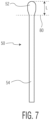
- the head portion is defined as the area above the tail portion wherein the tail portion is the part of the treated discrete area 50 where a relatively uniform width is achieved as shown in FIG. 7 .
- the head portion can have various irregular shapes and can generally have a width that is wider than the width of the tail portion 54.
- the position of the line of demarcation 80 is where the head portion 52 tapers inward and joins the tail portion 54.
- the length of the treated discrete area 50 can vary depending upon the particular application but can be less than about 80 mm, such as less than about 70 mm, such as less than about 60 mm, such as less than about 50 mm, such as less than about 45 mm, such as less than about 40 mm, such as less than about 35 mm, such as less than about 30 mm, such as less than about 25 mm, such as less than about 20 mm, such as even less than about 15 mm.
- These short lengths can be achieved even when the web of material 20 is being conveyed at extremely fast speeds, such as greater than about 400 m/min.
- the amount of adhesive composition contained in each head portion 52 in relation to the amount of adhesive composition contained in a corresponding tail portion 54 can vary by controlling the web speed, the web deflecting device 30 and the adhesive flow rates.
- the amount of adhesive composition contained in each head portion 52 in comparison to the amount of adhesive composition contained in each tail portion 54 can be from about 95:5 to about 5:95. In one embodiment, however, a greater amount of adhesive composition may be contained in head portion 52 in relation to the amount of adhesive composition as contained in the tail portion 54.
- a bead of the adhesive composition first contacts the web of material 20 during the process forming the head portion 52 followed by formation of the tail portion 54 through a smearing process.
- the amount of adhesive composition contained in each head portion 52 in comparison to the amount of adhesive composition contained in each tail portion 54 can be from about 90:10 to about 60:40.
- the adhesive composition can have a basis weight (i.e. amount of adhesive composition per area on the web) in the head portion 52 that is greater than the basis weight of the adhesive composition in the tail portion 54.
- the basis weight of the adhesive composition in the head portion 52 can be at least about 20%, such as at least about 30%, such as at least about 40%, such as least about 50%, such as least about 60%, such as least about 70%, such as least about 80%, such as least about 90%, such as even at least about 100% greater than the basis weight of the adhesive composition in the tail portion 54.
- the web of material 20 can be used to construct many different types of products.
- the web of material 20 can be incorporated into an absorbent article.
- the adhesive composition is applied to the web during the process in order to attach a separate piece of material to the web for constructing a particular portion of the product.
- the absorbent article for instance, may comprise a diaper, a training pant, a swim pant, an adult incontinence product, a feminine hygiene product, or the like.
- the adhesive composition may be applied to the web of material 20 in order to attach side panels to an absorbent article, such as elastic side panels.
- the adhesive composition may be used to attach fastener panels, such as hook and loop fasteners, to the material that serve as attachment devices for attaching the diaper to the wearer.
- the adhesive composition can be used to form a pocket within the absorbent article.
Landscapes
- Life Sciences & Earth Sciences (AREA)
- Engineering & Computer Science (AREA)
- Wood Science & Technology (AREA)
- Application Of Or Painting With Fluid Materials (AREA)
- Absorbent Articles And Supports Therefor (AREA)
- Coating Apparatus (AREA)
- Adhesives Or Adhesive Processes (AREA)
Description
- Absorbent articles, such as disposable diapers, training pants, adult incontinence articles and the like, generally include several different components which are adhesively bonded together. For example, adhesive has been used to bond individual layers of the absorbent article, such as the outer cover and body side liner, together. Adhesive has also been used to bond discrete pieces, such as the fasteners and leg elastics, to the article. Typically, the adhesive has been sprayed or slot-coated on the continuous moving web which provides the absorbent articles. The sufficiency of the adhesive bond between the components of the absorbent article is generally dependent upon the amount of adhesive, the type of adhesive and the pattern of the adhesive.
- Various techniques for spraying an adhesive on a moving web are well known to those skilled in the art. Many conventional techniques have relied upon pressure to deliver the adhesive to a plurality of nozzles and spray the adhesive from the nozzles onto a moving web. In such conventional techniques, the amount and pattern of the spray of adhesive is directly dependent upon the pressure at each nozzle.
- For example, one conventional technique which relies upon pressure for spraying the adhesive involves an apparatus having a plurality of nozzles which are connected to a manifold. Adhesive is supplied to the manifold and nozzles by a single large, central tank of molten adhesive. The tank of adhesive is pressurized to deliver the adhesive from the tank to the manifold and to the individual nozzles. The individual nozzles are then independently turned on and off to spray the adhesive. The amount of adhesive which is dispensed from the nozzles is dependent upon the pressure at the tank of adhesive, the length of the supply lines, the number of nozzles which are being operated at a given point in time and whether the nozzles are operating efficiently.
- Various problems, however, exist is spraying an adhesive on a moving web. For instance, it is very difficult to control the placement of the adhesive on the web and to control the amount of adhesive applied to the web. Collateral spray of adhesive, for instance, can land on portions of the moving web where adhesive is not desired and/or on the processing equipment. In addition, some spray adhesives lack adhesive strength, especially when applying elastic components to a web that are later to be stretched.
- In addition to spraying adhesives onto a moving web, hot melt adhesives are also applied by being extruded onto a web using a slot coater or similar device. In these processes, the moving web contacts the adhesive head and the adhesive is periodically applied to the web. At faster web speeds, however, the application of a hot melt adhesive through extrusion can be the rate limiting step in the process. For instance, due to the speed of the web, even short pulses of adhesive form relatively long lengths of adhesive streaks. For instance, during conventional processes, the moving web is in constant contact with the adhesive head. A single bead of adhesive extruded from the adhesive head contacts the moving web and is smeared over the web as the web is moving past the adhesive head. These adhesive streaks typically must be covered by a material joined to the web. Thus, long adhesive streaks require longer pieces of material, which may represent excess material and waste in the final product. In order to create shorter streaks of adhesive, the process speeds, i.e. the speed of the moving web, must be decreased. Consequently, the adhesive application step of the process can be a rate limiting step and can adversely affect the overall throughput of the process.
- In addition to problems experienced in applying adhesives at fast speeds, adhesive applicators as described above also have experienced problems with maintaining uniform flow through the adhesive head due to clogging and other issues. For instance, over time, adhesive heads can generate significant amounts of dust and lint. In addition, adhesive build up on the head can occur over time. Thus, adhesive applicators are typically periodically cleaned which can require downtime of the process.
- In view of the above, a need exists for an improved method and system for applying an adhesive, such as a hot melt adhesive, to a moving web. More particularly, a need exists for an adhesive applicator system and method capable of controlling the amount of adhesive being applied to a web while the web is moving at very fast speeds.
US 4371571 discloses fluid adhesive and similar applicator systems and methods.US 2013/0260031 discloses an adhesive agent applying apparatus.US 2029922 discloses an apparatus and method for uniting layers of material.US 2004/161531 discloses a process for applying glue, in particular glue of the hot-melt type.US 5614023 discloses a method of applying a liquid to a flexible substrate. - In general, the present disclosure is directed to a system and process for applying an adhesive to a moving web of material. The system and process of the present disclosure are capable of dramatically reducing the adhesive application length when the web of material is running at high speeds in comparison to conventional systems. In addition, the system and process of the present disclosure is also capable of providing better control of application of the adhesive. In addition, the system and process of the present disclosure can apply adhesives to moving webs in unique patterns that can result in improved bonding between two materials during the process.
- The present disclosure is directed to a system for applying an adhesive to a moving web of material in accordance with claim 1. For instance, the adhesive control device can be configured to enable and disable flow of adhesive through the nozzle prior to the nozzle contacting a moving web of material. Alternatively, the adhesive control device can be configured to enable flow of adhesive through the nozzle prior to contact with the moving web and then to disable flow of an adhesive through the nozzle while the nozzle is in contact with the moving web of material. In this manner, lesser of amounts of adhesive can be applied to the web even at extremely fast speeds. In addition, the length of adhesive applied to the moving web can be minimized in relation to the amount of time the moving web is in contact with the nozzle.
- In one embodiment, the nozzle can include a plurality of spaced apart exit ports for depositing a plurality of parallel and vertical adhesive streaks onto the moving web of material. For instance, the nozzle can include from about 2 to about 15 exit ports.
- The web deflecting device can cause the moving web of material to contact the nozzle by moving the web and/or by moving the nozzle. In one embodiment, for instance, the web deflecting device comprises a deflecting cam that moves the moving web of material periodically into contact with the nozzle. For instance, the deflecting cam can be attached to a rotating roll positioned adjacent to the moving web of material. The deflecting cam can project from the surface of the rotating roll. As the roll rotates, the deflecting cam contacts the web and pushes the web into contact with the nozzle. In one embodiment, the rotating roll can be configured to rotate at a speed such that a web contacting surface on the deflecting cam moves at a speed that is faster than the speed at which the web of material is moving.
- In one embodiment, the action of the web contacting the nozzle not only removes adhesive from the nozzle but also wipes the nozzle head in a manner that prevents the buildup of adhesive and prevents the buildup of lint and dust.
- The deflecting device causes the moving web of material to contact the nozzle in a manner such that the web forms a maximum exit angle with the nozzle. The maximum exit angle is from about 5° to about 30° in relation to a horizontal plane that is perpendicular to an exit port on the nozzle. During the process, the exit angle can constantly change from a minimum exit angle to a maximum exit angle as the deflecting device deflects the web.
- The deflecting device can be positioned downstream from the nozzle or can be positioned upstream from the nozzle. In one embodiment, the deflecting device contacts the moving web of material in a manner that causes the web of material to increase in tension during contact with the nozzle. Increasing the tension of the web can further improve application of the adhesive to the web.
In one embodiment, the web conveying device moves the web of material at a speed of at least 400 m/min, such as at least about 450 m/min, such as at least about 500 m/min, such as at least about 550 m/min, such as even greater than about 600 m/min. - The present disclosure is also directed to a process for applying an adhesive to a moving web of material in accordance with claim 11. In this manner, the nozzle applies at least one vertical streak of an adhesive to the web. The flow of adhesive through the nozzle, for instance, can be intermittent. For example, in one embodiment, the process includes the step of starting and stopping the flow of adhesive through the nozzle prior to contacting the nozzle with the moving web. In an alternative process, flow of adhesive through the nozzle is started prior to contact with the moving web of material and is stopped during contact with the moving web.
- The adhesive can comprise a pressure sensitive hot melt adhesive. In one embodiment, the nozzle can include a plurality of exit ports for forming a plurality of parallel and vertical adhesive streaks on the moving web of material. In one embodiment, the web of material is moving at a speed of at least 400 m/min and each vertical streak of adhesive has a length of less than about 80 mm, such as less than about 45 mm, such as less than about 30 mm, such as less than about 20 mm. In one embodiment, the process includes the steps of incorporating the moving web of material into a product, such as an absorbent article or into a packaging product.
- Other features and aspects of the present disclosure are discussed in greater detail below.
- A full and enabling disclosure of the present disclosure is set forth more particularly in the remainder of the specification, including reference to the accompanying figures, in which:
-
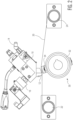
Fig. 1 is a side view of one embodiment of a system for applying an adhesive to a moving web of material illustrating an adhesive applicator in relation to a web deflecting device; -
Fig. 2 is a side view of the system illustrated inFig. 1 showing the web deflecting device deflecting a web of material into contact with an adhesive nozzle; -
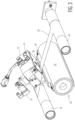
Fig. 3 is a perspective view of the system for applying an adhesive to a moving web as shown inFigs. 1 and2 ; -
Fig. 4 is a side view of a nozzle for an adhesive applicator illustrating an exit angle; -
Fig. 5 is a plan view of a web of material illustrating an adhesive pattern applied to the material; -
Fig. 6 is a cross sectional view of the woven material illustrated inFig. 5 ; and -
Fig. 7 is a plan view of an enlarged view of one of the adhesive streaks shown inFig. 5 . - Repeat use of reference characters in the present specification and drawings is intended to represent the same or analogous features or elements of the disclosure.
- It is to be understood by one of ordinary skill in the art that the present discussion is a description of exemplary embodiments only, and is not intended as limiting the broader aspects of the present disclosure.
- In general, the present disclosure is directed to a system and method for accurately applying an adhesive onto a continuously moving web in a desired pattern. The apparatus and method are particularly useful for applying viscous adhesives, such as hot melt adhesives, to bond together different components of various different products, such as a disposable absorbent article. The system and method of the present disclosure, for instance, can be used to bond elastic panels, side panels, fastener panels, leg elastics, and the like to other materials during the production of an absorbent article, such as a diaper, an adult incontinence product, a training pant, a swim pant, a feminine hygiene product, or the like. It should be understood, however, that the system and process can also be used in numerous and various other applications and is not in any way limited to the production of absorbent articles.
- The system of the present disclosure generally includes a web conveying device that conveys the web adjacent to an adhesive applicator. The system further includes a web deflecting device that periodically causes the moving web to contact a nozzle of the adhesive applicator. Adhesive, in one embodiment, intermittently exits the nozzle of the adhesive applicator for application to the web. The adhesive flows from the nozzle prior to contact with the web. In this manner, during contact with the web, the adhesive is smeared onto the web in a controlled manner. The system and process of the present disclosure provide numerous benefits and advantages in processing webs of material. For instance, the amount of adhesive and the length of adhesive that extends in the machine direction (i.e. moving direction or longitudinal direction) can be minimized at extremely fast web speeds. In addition, controlling the timing of supply of adhesive to the nozzle allows for extremely accurate control over the desired amount of adhesive to be applied to the web. In this manner, less materials are needed in constructing the product, such as the absorbent article. In addition, line speeds can be increased in comparison to the use of conventional adhesive applicators.
- Referring to
FIGS. 1 through 3 , one embodiment of an adhesive applicator system made in accordance with the present disclosure is illustrated. As shown, the system includes anadhesive applicator 10 that includes anozzle 12. Thenozzle 12, for instance, may comprise a slot coating device. In one embodiment, thenozzle 12 can include a single adhesive orifice or slot. The orifice may be designed to apply adhesive to a particular location on a web of material or can be designed to apply adhesive over the entire width of the material. - Alternatively, the
nozzle 12 may include a plurality of spaced apart exit ports or slots for depositing a plurality of parallel treated discrete areas of adhesive onto a moving web. Thenozzle 12 can receive adhesive from an adhesive supply. For instance, as shown in the figures, theadhesive applicator 10 can include anadhesive supply line 14 in fluid communication with thenozzle 12. - The
adhesive applicator 10 further includes an adhesiveflow control device 16. The adhesiveflow control device 16 controls the flow of adhesive from thesupply line 14 to the one or more exit ports on thenozzle 12. Theflow control device 16 can comprise, for instance, any suitable valve or similar device. In one embodiment, for instance, the adhesiveflow control device 16 may comprise a solenoid valve. In one embodiment, the adhesiveflow control device 16 can be in communication with a controller, such as one or more microprocessors. The controller can be configured to control the adhesiveflow control device 16 for enabling and disabling flow of an adhesive through thenozzle 12 at desired times, such as during periodic intervals. For example, the adhesiveflow control device 16 may open the valve to allow the adhesive to flow through thenozzle 12 and may close the valve to cease the flow of adhesive through thenozzle 12. - The
adhesive applicator 10 can include a singleadhesive control device 16 or can include multiple devices. Additionally, theadhesive applicator 10 can include a single valve or multiple valves. For instance, if thenozzle 12 includes a plurality of exit ports, theadhesive applicator 10 can include a corresponding plurality ofcontrol devices 16 and/or valves for controlling each of the individual exit ports. Alternatively, asingle control device 16, along with either a single valve or multiple valves, can control flow through all of the exit ports simultaneously. - The system of the present disclosure further includes a web conveying device for conveying a web of material. As shown in
FIGS. 1 through 3 , the web conveying device can include guide rolls 22 and 24 for supporting a web ofmaterial 20. As shown inFIG. 1 , the guide rolls 22 and 24 are positioned to convey the web ofmaterial 20 in close proximity to thenozzle 12 without contacting the nozzle. The web conveying device can be designed to convey theweb 20 at very fast speeds. For instance, theweb 20 during processing can be moving at a speed of at least about 100 m/min, such as at least about 200 m/min, such as at least about 300 m/min, such as at least about 400 m/min, such as at least about 450 m/min, such as at least about 500 m/min, such as at least about 550 m/min, such as at least about 600 m/min. The speed of the web ofmaterial 20 is generally less than about 1,000 m/min, such as less than about 800 m/min. - In accordance with the present disclosure, the system further includes a
web deflecting device 30 that is designed to periodically cause contact between thenozzle 12 and the web ofmaterial 20. In the embodiment illustrated inFIGS. 1 through 3 , the web deflecting device contacts theweb 20 moving the web into contact with thenozzle 12. In other embodiments, however, the web deflecting device may move the nozzle into contact with the web. In general, the web deflecting device can be any suitable device or apparatus capable of causing contact between thenozzle 12 and the moving web ofmaterial 20. - In the embodiment illustrated in
FIGS. 1 through 3 , the web deflecting device includes arotating roll 32 attached to a deflectingcam 34. The deflectingcam 34 extends radially outward from theroll 32 and includes aweb contacting surface 36. Theweb contacting surface 36 can have a width that can correspond with the width of the movingweb 20. In general, the width of theweb contacting surface 36 is at least as wide as the one or more exit ports located on thenozzle 12. - In order to apply adhesive from the
nozzle 12 of theadhesive applicator 10 to the movingweb 20, theweb deflecting device 30 is rotated, which causes theweb contacting surface 36 of the deflectingcam 34 to contact theweb 20 as shown inFIGS. 2 and3 . For at least a portion of the rotation of theweb deflecting device 30 where the deflectingcam 34 is in contact with theweb 20, theweb 20 comes into contact with thenozzle 12. During contact between the web ofmaterial 20 and thenozzle 12, adhesive is transferred to the web. Theweb deflecting device 30 continues to rotate causing the deflectingcam 34 to rotate out of the path of travel of the web ofmaterial 20 causing the web to once again move away from thenozzle 12 and to continue to move downstream in a noncontacting relationship with theadhesive applicator 10. - In order to apply adhesive to the web of
material 20, theadhesive control device 16 can be used to control the flow of adhesive from thenozzle 12 in a manner that forms the desired pattern of adhesive onto the web. For example, enabling flow of adhesive and disabling flow of adhesive from the nozzle in conjunction with the timing of contact between the nozzle and the moving web can be varied and adjusted in order to obtain an optimum result for the particular application. - In one embodiment, for instance, flow of adhesive through the
nozzle 12 is started and stopped prior to any contact of thenozzle 12 with theweb 20. For example, theflow control device 16 may cause the one or more valves to open for a period of time, allowing adhesive to flow to thenozzle 12, and then close the one or more valves, causing the adhesive to cease flowing to thenozzle 12, all during a time period where theweb 20 is not in contact with thenozzle 12. In this embodiment, for instance, a bead of adhesive is discharged from the exit port of thenozzle 12. Due to the fluid properties of the adhesive, the adhesive remains adhered to the nozzle head. The web ofmaterial 20 is then brought into contact with the bottom surface of thenozzle 12 by theweb deflecting device 30. The bead of adhesive is then removed from the surface of thenozzle 12 due to contact with the moving web. Due to the manner in which the adhesive is wiped off thenozzle 12, a streak of adhesive is then deposited onto theweb 20 in the longitudinal direction or the machine direction of the moving web. - In an alternative embodiment, flow of adhesive through the
nozzle 12 is enabled by theadhesive control device 16 prior to contact with the moving web. For example, theflow control device 16 may cause the one or more valves to open allowing adhesive to flow to thenozzle 12. In this embodiment, however, the one or more valves remain open as theweb 20 contacts thenozzle 12. Accordingly, flow of adhesive through thenozzle 12 continues for at least a portion of the time period during which thenozzle 12 is in contact with theweb 20. Theadhesive control device 16 can disable flow of adhesive at any point during contact with theweb 20, for instance by closing the one or more valves. For example, flow of adhesive can be discontinued just as theweb 20 contacts thenozzle 12 for applying lesser amounts of adhesive or can discontinue the flow of adhesive generally at the same time theweb 20 separates from thenozzle 12 for applying greater amounts of adhesive. In still further embodiments, the flow of adhesive may be stopped after contact between theweb 20 and thenozzle 12 has ceased. - Thus, the system and process of the present disclosure provides a significant amount of variability in the amount of adhesive that is applied to the web depending upon the application. The length of adhesive in the longitudinal direction can be controlled by controlling the amount of adhesive that flows through the
nozzle 12, the duration of flow of adhesive, and/or the timing of the flow of adhesive in relation to contact with the moving web. - In accordance with the present disclosure, the amount of time that the
web 20 contacts the surface of thenozzle 12 can also be controlled depending upon various factors. The amount of time theweb 20 remains in contact with thenozzle 12, for instance, depends upon the speed of the web and the construction of theweb deflecting device 30, including the shape of the deflectingcam 34. The contact time, for instance, can depend upon the amount theweb 20 is deflected towards theadhesive applicator 10 and can also depend upon the length of theweb contacting surface 36 in the longitudinal direction. In one embodiment, for instance, the system of the present disclosure can be configured such that the web ofmaterial 20 contacts thenozzle 12 for at least about 4 milliseconds, such as at least about 6 milliseconds, such as at least about 8 milliseconds, such as at least about 10 milliseconds, such as at least about 12 milliseconds. The contact time is generally less than about 1 second, such as less than about 500 milliseconds, such as less than about 200 milliseconds, such as less than about 100 milliseconds, such as less than about 50 milliseconds, such as less than about 40 milliseconds, such as less than about 30 milliseconds, such as less than about 20 milliseconds, such as less than about 15 milliseconds. - During the process, the adhesive is deposited onto the moving web of
material 20 so as to form treated discrete areas on the web. For instance, when thenozzle 12 includes a plurality of spaced apart exit ports, a pattern of treated discrete areas can be formed on one surface of the movingweb 20. The treated discrete areas are generally parallel to each other and extend in a longitudinal direction or the machine direction of theweb 20. Due to the speed of the moving web and continuous contact between the web and the adhesive nozzle, conventional adhesive applicators tended to apply relatively long streaks of adhesive to the web and provided little to no control over the adhesive pattern. The system of the present disclosure, however can apply relatively short streaks of adhesive to a web ofmaterial 20 moving at very rapid speeds. For example, for a web ofmaterial 20 moving at a speed of greater than about 100 m/min, such as greater than about 300 m/min, such as even greater than about 600 m/min, the streaks of adhesive can have a length in the longitudinal direction of generally less than about 80 mm, such as less than about 60 mm, such as less than about 50 mm, such as less than about 45 mm, such as less than about 40 mm, such as less than about 30 mm, such as less than about 25 mm, such as less than about 20 mm, such as less than about 15 mm, such as less than about 13 mm, such as less than about 10 mm, such as less than about 8 mm, such as even less than about 5 mm. The adhesive lengths are generally greater than about 2 mm, such as greater than about 4 mm, such as greater than about 5mm. - In addition to being capable of controlling the amount of adhesive applied to the moving
web 20 and being able to reduce the adhesive application length when running at high speeds, the process and system of the present disclosure also provides for a self-cleaning mechanism of the nozzle. For example, by periodically contacting thenozzle 12 as shown isFIGS. 1 through 3 , the web ofmaterial 20 wipes the surface of thenozzle 12 clean during application of the adhesive to theweb 20. Thus, during application of the adhesive to the movingweb 20, theweb 20 wipes away the adhesive residing on thenozzle 12 and simultaneously wipes away any lint on the nozzle head. - In one embodiment the deflecting
cam 34 of theweb deflecting device 30 contacts the movingweb 20 and pushes the web above the exit ports on thenozzle 12. In this manner, theweb 20 forms an exit angle with thenozzle 12. - Referring to
FIG. 4 , for instance, the exit ports on thenozzle 12 are perpendicular to ahorizontal plane 40. When the web ofmaterial 20 is deflected, the web ofmaterial 20 forms anexit angle 42 in relation to thehorizontal plane 40. During contact with thenozzle 12, theexit angle 42 of the web ofmaterial 20 with the exit ports on the nozzle changes from a minimum exit angle to a maximum exit angle. The maximum exit angle during the process is greater than about 5°, such as greater than about 7°, such as greater than about 10°, such as greater than about 12°, such as greater than about 15°, such as greater than about 18°, such as greater than
about 20°, such as greater than about 22°, such as greater than about 25°. The maximum exit angle is less than 30°, such as less than about 25°, such as less than about 20°. As theexit angle 42 of the web ofmaterial 20 changes with respect to thenozzle 12, the wiping motion of theweb 20 against thenozzle 12 changes further facilitating cleaning of thenozzle 12 during the process. Changing theexit angle 42 during the process also facilitates application of adhesive to theweb 20 and provides greater uniformity and control. - In addition to forming and changing the exit angle of the
web 20 with thenozzle 12, the tension of theweb 20 as it contacts thenozzle 12 can also be varied in order to facilitate application of the adhesive to theweb 20 and/or further clean the surface of thenozzle 12 during contact. For example, in one embodiment, therotating roll 32 of theweb deflecting device 30 can be rotated so that theweb contacting surface 36 of the deflectingcam 34 contacts theweb 20 at a speed that is faster than the speed theweb 20 is moving. In this manner, tension in theweb 20 can be increased during contact with thenozzle 12. For example, theweb contacting surface 36 can be moving at a speed that is at least about 1% greater, such as at least about 2% greater, such as at least about 3% greater, such as at least about 4% greater, such as at least about 5% greater than the speed at which theweb 20 is moving during contact with theweb 20. The speed of theweb contacting surface 36 is generally moving at a speed that is no more than about 30% greater than the speed of theweb 20, such as no more than about 20% greater than the speed of theweb 20, such as no more than about 10% greater than the speed of theweb 20. - In the embodiment illustrated in
FIGS. 1 through 3 , theweb deflecting device 30 is positioned in the system such that theweb contacting surface 36 contacts theweb 20 downstream from thenozzle 12. For instance, theweb contacting surface 36 can contact the web of material 20 a distance downstream from the one or more exit ports from the nozzle 12 a distance of greater than about 20 mm, such as greater than about 40mm, such as greater than about 60 mm, such as greater than about 80 mm, such as greater than about 100 mm. The distance downstream can generally be less than about 1000 mm, such as less than about 500 mm, such as less than about 100 mm. - In an alternative embodiment, instead of contacting the
web 20 downstream from the nozzle12, theweb deflecting device 30 can also be positioned to contact theweb 20 upstream from thenozzle 12. When contacting theweb 20 upstream from thenozzle 12, an entrance angle will be formed between theweb 20 and a horizontal plane that is perpendicular to the exit port on thenozzle 12. The entrance angle can have the same dimensions as theexit angle 42 described above. - It should also be understood that the
web deflecting device 30 as shown inFIGS. 1 through 3 represents one embodiment of theweb deflecting device 30 and that various other web deflecting devices may be utilized. For instance, in an alternative embodiment, theweb deflecting device 30 may be configured to move the deflectingcam 34 up and down instead of in a rotating motion. - The adhesive that is emitted or extruded from the
nozzle 12 in accordance with the present disclosure can vary depending upon various factors including the type ofmaterial 20 being processed, the type of product being formed, and the type of opposing material that is later attached to the web ofmaterial 20. In one embodiment, for instance, the adhesive applied to theweb 20 may comprise a hot melt adhesive, such as a hot melt, pressure-sensitive adhesive. For example, in one embodiment, an adhesive composition is applied to the web ofmaterial 20 containing a thermoplastic polymer which may comprise an elastomeric polymer. The polymer may be combined with one or more tackifying resins and/or one or more plasticizers. Optionally, the adhesive composition may also contain an oil, a wax, and/or a stabilizer. - In one embodiment, the polymer contained in the adhesive composition is a polyolefin polymer. The polyolefin polymer may comprise a polypropylene, a polyethylene, copolymers thereof, homopolymers thereof, and the like. In an alternative embodiment, the polymer contained in the polymer composition contains a block copolymer, such as a styrene block copolymer. The block copolymer, for instance, may comprise, a polystyrene-polybutadiene-polystyrene polymer, a polystyrene-polyisoprene-polystyrene polymer, a polystyrene-polyisoprene-polybutadiene-polystyrene polymer, a polystyrene-poly(ethylenebutylene)-polystyrene polymer, a polystyrene-poly(ethylenepropylene)-polystyrene polymer, or mixtures thereof. One or more of the block copolymers can also be combined with a polyolefin as described above.
- In general, the adhesive composition can contain one or more polymers in an amount greater than about 25% by weight, such as in an amount greater than about 30% by weight, such as in an amount greater than about 35% by weight, such as in an amount greater than about 40% by weight, such as in an amount greater than about 50% by weight, such as in an amount greater than about 60% by weight, such as in an amount greater than about 70% by weight. One or more polymers may be contained in the adhesive composition in an amount less than about 98% by weight, such as in an amount less than about 80% by weight, such as in an amount less than about 70% by weight, such as in an amount less than about 60% by weight, such as in an amount less than about 50% by weight.
- Tackifying resins that may be combined with the polymer include, for instance, colophony rosins, terpene resins, copolymers based on natural terpenes, or resins that have been hydrogenated, polymerized or copolymerized with an aromatic hydrocarbon.
- The use of a tackifying resin in an adhesive composition is optional. When present the tackifying resin can be included in the composition generally in an amount greater than about 10% by weight, such as in an amount greater than about 20% by weight, such as in an amount greater than about 30% by weight. Tackifying resins are generally present in an amount less than about 70% by weight, such as in an amount less than about 60% by weight, such as in an amount less than about 50% by weight.
- Use of plasticizers in the adhesive composition is also optional. When present, a plasticizer can be included in the composition in an amount greater than about 5% by weight, such as in an amount greater than about 10% by weight, such as in an amount greater than about 15% by weight, and generally less than about 30% by weight, such as in an amount less than about 25% by weight, such as in an amount less than about 20% by weight. Suitable plasticizers that may be included in the adhesive composition include mineral oil, vegetable oils, animal oils, and derivatives thereof. Petroleum derived oils may also be used as plasticizers.
- As described above, beginning a flow of the adhesive composition through the
nozzle 12 can occur prior to contact of thenozzle 12 with the movingweb 20. Thus, the adhesive composition used in the present disclosure, in one embodiment, has sufficient cohesive properties such that the adhesive will not drip from the surface of the novel during flow. For example, in one embodiment, the adhesive composition has sufficient viscosity and cohesiveness to remain adhered to the surface of thenozzle 12 until contact with the movingweb 20. - For instance, the adhesive composition can have a viscosity at 350°F (176°C) of generally greater than about 500cps (0.5 Pa-s) such as greater than about 600 cps (0,6 Pa-s) such as greater than about 700 cps, such as greater than about 800 cps, such as greater than about 900 cps, such as greater than about 1000 cps, such as greater than about 1200 cps, such as greater than about 1400 cps, such as greater than about 1600 cps, such as greater than about 1800 cps, such as greater than about 2000 cps, such as greater than about 2200 cps, such as greater than about 2500 cps, such as greater than about 2700 cps, such as greater than about 3000 cps, such as greater than about 3500 cps, such as greater than about 4000 cps (4 Pa-s) ( 1 cps = 0,001 Pa-s) The viscosity of the adhesive composition is generally less than about 90,000 cps at 350°F (176°C), such as less than about 80,000 cps, such as less than about 70,000 cps, such as less than about 60,000 cps, such as less than about 50,000 cps, such as less than about 40,000 cps, such as less than about 30,000 cps, such as less than about 20,000 cps, such as less than about 10,000 cps, such as less than about 8000 cps, such as less than about 5000 cps, such as less than about 3000 cps (3Pa-s; 1 cps = 0,001 Pa-s)
- The Viscosity Test is conducted in accordance with ASTM Test Method D3236-88, entitled "Standard Test Method for Apparent Viscosity of Hot Melt Adhesives and Coating Materials," The viscometer used is that made by Brookfield Engineering Laboratories of Middleboro, Mass., U.S.A., as model RVDV III. The spindle number to use in conducting the ASTM Test Method is SC4-27. The sample size should be about 10.5 grams of adhesive. The spindle speed (rpm) is set to a value that results in a torque reading in the range of 20 percent to 80 percent. A reading should be taken every few minutes for about 15 minutes, or until the viscosity values stabilize, after which the final viscosity reading (in centipoises) is recorded.
- The system and process of the present disclosure is capable of producing a unique adhesive pattern applied to the moving
web 20. For instance, through the process of the present disclosure, an adhesive pattern of treated discrete areas can be formed onto the movingweb 20. These treated discrete areas can have many beneficial properties for attaching the movingweb 20 to an adjoining surface, such as to another piece of material. For example, in one embodiment, the adhesive pattern made according to the present disclosure can be applied to theweb 20 at high speeds while minimizing the amount of materials needed to construct a product. In addition, the adhesive pattern may include treated discrete areas having a unique adhesive profile that facilitates attachment to another material and provides for a strong bond. - For example, in one embodiment, the
nozzle 12 of theadhesive applicator 10 includes a plurality of exit ports. For instance, thenozzle 12 can include greater than about 2 exit ports, such as greater than about 4 exit ports, such as greater than about 6 exit ports, such as greater than about 8 exit ports, such as greater than about 10 exit ports and generally less than about 30 exit ports, such as less than about 20 exit ports, such as less than about 15 exit ports that extend along the width of the web ofmaterial 20. The plurality of exit ports can be used to form a pattern of treated discrete areas on the top surface of the movingweb 20. The treated discrete areas form streaks on the surface of theweb 20 and generally extend in the longitudinal direction of theweb 20 or the machine direction. - For instance, one example of a pattern of treated discrete areas of an adhesive composition is shown in
FIGS. 5 and 6 . Referring toFIG. 5 , for example, a plurality of vertically extending treateddiscrete areas 50 are shown applied to theweb 20. The treateddiscrete areas 50 are generally parallel to each other in the length direction of theweb 20. InFIG. 5 , six parallel discrete areas are shown. It should be understood, however, that a greater number or lesser number of treated discrete areas may be formed on theweb 20. For example, in one embodiment, from about 2 to about 30 treated discrete areas, such as from about 3 to about 12 treated discrete areas can be formed on the web ofmaterial 20. - As shown in
FIG. 5 , in one embodiment, each treated discrete area can include ahead portion 52 integral with atail portion 54. Thehead portion 52 is formed when the web ofmaterial 20 first contacts thenozzle 12 during the process. Thetail 54, on the other hand, is formed as the web ofmaterial 20 moves across the head of thenozzle 12. A cross section of one of the treateddiscrete areas 50 showing thehead portion 52 and thetail portion 54 is illustrated inFIG. 6 . - Referring to
FIG. 7 , one of the treateddiscrete areas 50 is shown in greater detail. The treateddiscrete area 50 includes ahead portion 52 and atail portion 54. InFIG. 7 , abroken line 80 is used to illustrate where thehead portion 52 ends and thetail portion 54 begins. For most applications, thehead portion 52 is visually distinct from thetail portion 54. For example, in one embodiment, thehead portion 52 will appear more as a bead or glob of adhesive composition, while thetail portion 54 appears more like a smear or streak of the adhesive composition. As shown inFIG. 7 , thetail portion 54 typically has a more uniform width than thehead portion 52. The width of thetail portion 54 generally corresponds to the width of the exit orifice on thenozzle 12. As used herein, the head portion is defined as the area above the tail portion wherein the tail portion is the part of the treateddiscrete area 50 where a relatively uniform width is achieved as shown inFIG. 7 . The head portion, on the other hand, can have various irregular shapes and can generally have a width that is wider than the width of thetail portion 54. As shown inFIG. 7 , the position of the line ofdemarcation 80 is where thehead portion 52 tapers inward and joins thetail portion 54. - As shown in
FIG. 5 , in one embodiment, thehead portion 52 can have a maximum width that is wider than the maximum width of thecorresponding tail portion 54. Thetail portion 54, on the other hand, can be substantially longer than a correspondinghead portion 52. For example, the ratio of the length of thehead portion 52 to the length of thetail portion 54 is generally greater than about 1:5, such as greater than about 1:10, such as greater than about 1:15, such as greater than about 1:20. The ratio of the length of thehead portion 52 to the length of thetail portion 54 is generally less than about 1:100, such as less than about 1:40, such as less than about 1:30, such as less than about 1:20. As described above, the length of the treateddiscrete area 50 can vary depending upon the particular application but can be less than about 80 mm, such as less than about 70 mm, such as less than about 60 mm, such as less than about 50 mm, such as less than about 45 mm, such as less than about 40 mm, such as less than about 35 mm, such as less than about 30 mm, such as less than about 25 mm, such as less than about 20 mm, such as even less than about 15 mm. These short lengths can be achieved even when the web ofmaterial 20 is being conveyed at extremely fast speeds, such as greater than about 400 m/min. - The amount of adhesive composition contained in each
head portion 52 in relation to the amount of adhesive composition contained in acorresponding tail portion 54 can vary by controlling the web speed, theweb deflecting device 30 and the adhesive flow rates. For instance, in general, the amount of adhesive composition contained in eachhead portion 52 in comparison to the amount of adhesive composition contained in eachtail portion 54 can be from about 95:5 to about 5:95. In one embodiment, however, a greater amount of adhesive composition may be contained inhead portion 52 in relation to the amount of adhesive composition as contained in thetail portion 54. For example, a bead of the adhesive composition first contacts the web ofmaterial 20 during the process forming thehead portion 52 followed by formation of thetail portion 54 through a smearing process. In these embodiments, for instance, the amount of adhesive composition contained in eachhead portion 52 in comparison to the amount of adhesive composition contained in eachtail portion 54 can be from about 90:10 to about 60:40. - As shown in
FIG. 6 , for instance, the adhesive composition can have a basis weight (i.e. amount of adhesive composition per area on the web) in thehead portion 52 that is greater than the basis weight of the adhesive composition in thetail portion 54. For example, the basis weight of the adhesive composition in thehead portion 52 can be at least about 20%, such as at least about 30%, such as at least about 40%, such as least about 50%, such as least about 60%, such as least about 70%, such as least about 80%, such as least about 90%, such as even at least about 100% greater than the basis weight of the adhesive composition in thetail portion 54. - As used herein, the basis weight of the adhesive composition refers to an average basis weight over the particular area taken up by the adhesive composition on the
web 20. For instance, the basis weight of the adhesive composition in thehead portion 52 would be the average basis weight of the adhesive composition over the area occupied by thehead portion 52. Similarly, the basis weight of the adhesive composition in thetail portion 54 would be the average basis weight of the adhesive composition over the area occupied by thetail portion 54. - In one embodiment, the amount of adhesive in the
head portion 52 and the amount of adhesive in thetail portion 54 can be measured on a grams per linear meter basis. When measuring the amount of adhesive composition in the different portions based on a grams per linear meter basis, the total weight of the adhesive composition in grams in a particular portion can be divided by the length of the particular portion in the machine direction or in the length direction. For instance, as shown inFIG. 7 , the amount of adhesive composition in thehead portion 52 can first be measured. In one embodiment, for instance, thehead portion 52 can be removed from the web ofmaterial 20 and weighed in grams. An untreated portion of the web material can also be weighed having the exact same dimensions. The mass of the untreated material can then be subtracted from the mass of thehead portion 52 in order to arrive at the mass of the adhesive composition itself. The mass of the adhesive composition can then be divided by the length L as shown inFIG. 7 in order to calculate the amount of adhesive composition in grams per linear meter. A similar analysis can be conducted in order to determine the amount of adhesive composition present in thetail portion 54 in grams per linear meter. - In general, the adhesive composition in the
head portion 52 in grams per linear meter can be at least about 20%, such as at least about 30%, such as at least about 40%, such as at least about 50%, such as at least about 60%, such as at least about 70%, such as at least about 80%, such as at least about 90%, such as even at least about 100% greater than the amount of adhesive composition in grams per linear meter contained within thetail portion 54. For example, the adhesive composition in grams per linear meter in thehead portion 52 can be greater than about 150%, such as greater than about 200% than the amount of adhesive composition in grams per linear meter contained in thetail portion 54. In general, the ratio of the amount of adhesive composition in grams per linear meter in thehead portion 52 in comparison to the amount of adhesive composition in grams per linear meter in thetail portion 54 is less than about 50:1, such as less than about 20:1, such as less than about 10:1. - As shown in
FIG. 6 , thetail portion 54 can include amiddle section 58 and anend section 60. Theend section 60 can be located opposite thehead portion 52. In one embodiment, themiddle section 58 can have a substantially uniform basis weight while theend section 60 can have a gradually decreasing basis weight. For example, the basis weight of themiddle section 58 can vary by no more than about 15%, such as by no more than about 10%, such as by no more than about 5% over the length of the middle section. Theend section 60, on the other hand, can gradually decrease from the average basis weight of themiddle section 58 to zero. - In general, the web of
material 20 can comprise any suitable substrate for receiving the adhesive composition. The web ofmaterial 20, for instance, can comprise a single layer of material or can comprise a laminate. In one embodiment, the web ofmaterial 20 comprises a nonwoven web. For instance, the web ofmaterial 20 may comprise a spunbond web, a meltblown web, a coform web, a hydroentagled web, or the like. In one embodiment the web ofmaterial 20 can contain pulp fibers and may comprise a paper or tissue web. In another embodiment, the web ofmaterial 20 comprises a woven fabric or a knitted fabric. In still another alternative embodiment of the present disclosure, the web ofmaterial 20 can comprise a film. The film can be a single layer film or a multi-layer film. - In one embodiment, the web of
material 20 may comprise a laminate comprised of multiple layers. In one embodiment, for instance, the web ofmaterial 20 may comprise a spunbond/meltblown/spunbond web. - The web of
material 20 can be used to construct many different types of products. In one embodiment, for instance, the web ofmaterial 20 can be incorporated into an absorbent article. The adhesive composition is applied to the web during the process in order to attach a separate piece of material to the web for constructing a particular portion of the product. The absorbent article, for instance, may comprise a diaper, a training pant, a swim pant, an adult incontinence product, a feminine hygiene product, or the like. In one embodiment the adhesive composition may be applied to the web ofmaterial 20 in order to attach side panels to an absorbent article, such as elastic side panels. In an alternative embodiment, the adhesive composition may be used to attach fastener panels, such as hook and loop fasteners, to the material that serve as attachment devices for attaching the diaper to the wearer. In still another embodiment, the adhesive composition can be used to form a pocket within the absorbent article. - In another embodiment, the web of
material 20 may be used to produce various other products in addition to absorbent articles. For instance, in one embodiment, the web ofmaterial 20 may be used to form packaging. - These and other modifications and variations to the present invention may be practiced by those of ordinary skill in the art, without departing from the scope of the present invention, which is more particularly set forth in the appended claims. In addition, it should be understood that aspects of the various embodiments may be interchanged both in whole or in part. Furthermore, those of ordinary skill in the art will appreciate that the foregoing description is by way of example only, and is not intended to limit the invention so further described in such appended claims.
Claims (13)
- A system for applying an adhesive to a moving web of material (20) comprising:a nozzle (12) in fluid communication with an adhesive supply;a web conveying device for conveying a web of material, the web conveying device being configured to convey the web of material adjacent to the nozzle without contacting the nozzle;a web deflecting device (30) that periodically causes a moving web of material being conveyed by the web conveying device to contact the nozzle for a length of time;an adhesive control device (16) in communication with the nozzle, characterised in that the adhesive control device is configured to control a flow of adhesive through the nozzle in relation to contact of a moving web with the nozzle caused by the deflecting device such that flow of adhesive from the nozzle occurs prior to contact with the moving web of material;characterized in that the deflecting device is configured to cause a moving web of material to contact the nozzle in a manner such that the web forms a maximum exit angle (42) with the nozzle, the maximum exit angle being from 5° to 30° in relation to a horizontal plane that is perpendicular to an exit port on the nozzle, wherein the deflecting device is further configured such that the exit angle changes from a minimum exit angle to the maximum exit angle while the web of material is in contact with the nozzle.
- A system as defined in claim 1, wherein the nozzle includes a plurality of spaced apart exit ports for depositing a plurality of parallel and vertical adhesive streaks (50) onto a moving web of material, optionally wherein the nozzle includes from 2 to 15 exit ports.
- A system as defined in claim 1, wherein the adhesive control device is configured to enable and disable flow of adhesive through the nozzle prior to the moving web of material contacting the nozzle.
- A system as defined in claim 1, wherein the adhesive control device is configured to enable flow of adhesive through the nozzle prior to contact with a moving web of material and then to disable flow of an adhesive through the nozzle while the moving web of material is in contact with the nozzle.
- A system as defined in claim 1, wherein the web deflecting device comprises a deflecting cam (34) that moves a moving web of material periodically into contact with the nozzle.
- A system as defined in claim 1, wherein the web deflecting device is configured to move the nozzle into contact with a moving web of material.
- A system as defined in claim 5, wherein the deflecting cam is attached to a rotating roll (32) positioned adjacent to a moving web of material, the deflecting cam projecting from a surface of the rotating roll.
- A system as defined in claim 7, wherein the rotating roll is configured to rotate at a speed such that a web contacting surface of the deflecting cam moves at a speed that is faster than a speed of the web of material contacting the deflecting cam.
- A system as defined in any preceding claim, comprising:an adhesive supply line (14), wherein the adhesive supply is in fluid communication with the nozzle through said supply line;wherein the adhesive control device (16) is configured to control the flow of adhesive from the supply line to one or more exit ports of the nozzle;a controller, wherein the adhesive control device is in communication with the controller, the controller configured to control the adhesive control device for enabling and disabling flow of adhesive through the nozzle at desired times;optionally wherein the adhesive control device comprises one or more valves, wherein the one or more valves are configured to be opened by the adhesive control device to allow adhesive to flow through the nozzle to the one or more exit ports and are configured to be closed by the adhesive control device to cease the flow of adhesive through the nozzle to the one or more exit ports.
- A system as defined in claim 1, wherein the deflecting device contacts a moving web of material in a manner that causes the web of material to increase in tension during contact with the nozzle.
- A process for applying an adhesive to a moving web of material (20) using the system according to any one of the preceding claims, the process comprising:conveying a web of material adjacent to a nozzle (12) without contacting the nozzle;flowing an adhesive through the nozzle so as to exit the nozzle while the nozzle and the web are in a spaced apart relationship;periodically contacting the nozzle with the web of material while the web is moving, the nozzle applying at least one vertical streak (50) of adhesive to the web;characterized in that the web contacts the nozzle and forms and exit angle, and wherein, during contact with the moving web, the exit angle has a maximum exit angle of from 5° to 30°, the exit angle being measured in relation to a horizontal plane that is perpendicular to an exit port on the nozzle, wherein the exit angle changes from a minimum exit angle to the maximum exit angle while the web of material is in contact with the nozzle.
- A process as defined in claim 11, wherein flow of adhesive through the nozzle is started and stopped prior to contacting the nozzle with the moving web or wherein flow of adhesive through the nozzle is started prior to contact with the moving web of material and is stopped during contact with the moving web of material.
- A process as defined in claim 11, wherein the nozzle includes a plurality of exit ports and wherein the adhesive flows through the nozzle so as to form a plurality of parallel and vertical adhesive streaks (50) on the moving web of material; and wherein the web of material is moving at a speed of at least 400 m/min and wherein each vertical streak of adhesive has a length of less than 15 mm.
Applications Claiming Priority (1)
| Application Number | Priority Date | Filing Date | Title |
|---|---|---|---|
| PCT/US2017/039082 WO2018236395A1 (en) | 2017-06-23 | 2017-06-23 | APPARATUS AND METHOD FOR APPLYING ADHESIVE TO A MOVING BAND |
Publications (3)
| Publication Number | Publication Date |
|---|---|
| EP3641949A1 EP3641949A1 (en) | 2020-04-29 |
| EP3641949A4 EP3641949A4 (en) | 2021-03-03 |
| EP3641949B1 true EP3641949B1 (en) | 2025-04-09 |
Family
ID=64735764
Family Applications (1)
| Application Number | Title | Priority Date | Filing Date |
|---|---|---|---|
| EP17914951.3A Active EP3641949B1 (en) | 2017-06-23 | 2017-06-23 | System and process for applying an adhesive to a moving web |
Country Status (9)
| Country | Link |
|---|---|
| US (1) | US11878322B2 (en) |
| EP (1) | EP3641949B1 (en) |
| KR (1) | KR20200011543A (en) |
| CN (1) | CN110944757A (en) |
| AU (1) | AU2017420368B2 (en) |
| BR (1) | BR112019024978B1 (en) |
| MX (1) | MX2019014309A (en) |
| RU (1) | RU2745016C1 (en) |
| WO (1) | WO2018236395A1 (en) |
Families Citing this family (5)
| Publication number | Priority date | Publication date | Assignee | Title |
|---|---|---|---|---|
| GB2578694B (en) | 2017-06-23 | 2022-10-05 | Kimberly Clark Co | Adhesive pattern residing on a moving base web |
| JP7714873B2 (en) * | 2020-12-01 | 2025-07-30 | 王子ホールディングス株式会社 | Coating method and coating device |
| CN113275228A (en) * | 2021-05-20 | 2021-08-20 | 风迈智能科技(重庆)有限公司 | Live working RTV spraying method |
| US12246522B2 (en) * | 2021-10-05 | 2025-03-11 | The Boeing Company | Nozzles and systems for adhesively attaching a first part to a second part |
| IT202400004876A1 (en) * | 2024-03-05 | 2025-09-05 | Itapack S R L | ADHESIVE GROUP |
Family Cites Families (50)
| Publication number | Priority date | Publication date | Assignee | Title |
|---|---|---|---|---|
| US2029922A (en) | 1933-03-20 | 1936-02-04 | Gold Dust Corp | Method of and machine for uniting layers of material |
| US3926148A (en) | 1971-03-05 | 1975-12-16 | Honsel Karl Heinz | Application of adhesive to a moving web |
| US4020194A (en) * | 1974-12-30 | 1977-04-26 | Acumeter Laboratories, Inc. | Process for discontinuous coating of a web by periodic deflection thereof against a fluid coating |
| US4081301A (en) | 1975-10-30 | 1978-03-28 | The Procter & Gamble Company | Method and apparatus for continuously attaching discrete, stretched elastic strands to predetermined isolated portions of disposable abosrbent products |
| US4371571A (en) * | 1979-08-27 | 1983-02-01 | Acumeter Laboratories, Inc. | Wide-band and continuous line adhesive applicator and method for cigarette filter attachment and the like |
| US4608115A (en) | 1984-04-23 | 1986-08-26 | Kimberly-Clark Corporation | Revolving transfer roll |
| US4547243A (en) | 1984-10-09 | 1985-10-15 | Whitestone Products | Method and apparatus for continuously attaching elastic strands to disposable absorbent products |
| US4746545A (en) | 1985-12-16 | 1988-05-24 | Acumeter Laboratories, Inc. | Fluid coating and web-handling method and apparatus particularly adapted for low-tension and/or unevenly thick webs |
| US5049122A (en) | 1989-09-19 | 1991-09-17 | Marguip, Inc. | Apparatus for stripping scrap from die cut blanks |
| JP2601365B2 (en) | 1990-04-13 | 1997-04-16 | 富士写真フイルム株式会社 | Application method |
| CH690958A5 (en) | 1995-04-15 | 2001-03-15 | Bobst Sa | rotary cutting unit. |
| JPH07508923A (en) | 1992-07-08 | 1995-10-05 | ノードソン コーポレーション | Apparatus and method for applying separate foam coatings |
| US5363728A (en) | 1992-10-22 | 1994-11-15 | Elsner Engineering Works, Inc. | Two roll web cutter and method |
| US6776094B1 (en) | 1993-10-04 | 2004-08-17 | President & Fellows Of Harvard College | Kit For Microcontact Printing |
| US5494237A (en) | 1994-04-04 | 1996-02-27 | Alexander Machinery, Inc. | Oscillatable web guide roll and method of winding |
| DE19604761C2 (en) | 1996-02-09 | 1998-02-26 | Windmoeller & Hoelscher | Glue application device |
| JP3697315B2 (en) | 1996-05-13 | 2005-09-21 | 松下電器産業株式会社 | Adhesive applicator |
| CA2205622A1 (en) | 1997-05-16 | 1998-11-16 | Allan R. Prittie | Apparatus for removing waste windows from web carton material |
| RU2170241C2 (en) | 1999-08-26 | 2001-07-10 | Открытое акционерное общество "Химпласт" | Method of production of adhesive tape and unit for realization of this method |
| US6372064B1 (en) | 1999-12-13 | 2002-04-16 | C. G. Bretting Manufacturing Company, Inc. | Tail sealer apparatus and method |
| US7163740B2 (en) | 2001-06-02 | 2007-01-16 | The Procter & Gamble Company | Process for printing adhesives, adhesive articles and printing equipment |
| US6895649B2 (en) | 2001-08-29 | 2005-05-24 | Zuiko Corporation | Article production method |
| US6656401B1 (en) * | 2001-10-16 | 2003-12-02 | International Paper Company | Method for extrusion coating multiple webs |
| US6881471B2 (en) | 2001-10-25 | 2005-04-19 | The Procter & Gamble Company | High speed embossing and adhesive printing process and apparatus |
| US6652273B2 (en) | 2002-01-14 | 2003-11-25 | The Procter & Gamble Company | Apparatus and method for controlling the temperature of manufacturing equipment |
| EP1354638A3 (en) * | 2002-04-15 | 2004-11-03 | Fuji Photo Film Co., Ltd. | Method and apparatus for manufacturing pattern members using webs on which coating films have been formed |
| JP3680945B2 (en) | 2002-06-14 | 2005-08-10 | 株式会社東京機械製作所 | Automatic adjustment device for the customizing device |
| JP3669354B2 (en) | 2002-09-17 | 2005-07-06 | 株式会社東京機械製作所 | Folding device |
| EP1437303B2 (en) | 2003-01-08 | 2012-12-12 | Focke & Co. (GmbH & Co. KG) | Process and device for applying glue to packaging material |
| US6942610B2 (en) | 2003-05-28 | 2005-09-13 | Specialty Systems Advanced Machinery, Inc. | Web folding machine |
| US20050120947A1 (en) * | 2003-12-09 | 2005-06-09 | Konica Minolta Photo Imaging, Inc. | Coating apparatus and coating method |
| MXPA04000089A (en) | 2003-12-19 | 2005-06-23 | Grupo P I Mabe Sa De C V | Method for applying elastic adhesive. |
| US20050137549A1 (en) | 2003-12-22 | 2005-06-23 | Kimberly-Clark Worldwide, Inc. | Use of swirl-like adhesive patterns in the formation of absorbent articles |
| WO2005065248A2 (en) * | 2003-12-24 | 2005-07-21 | Dsg Technology Holdings Ltd | A system and process for making an elastic composit |
| US7163133B2 (en) | 2004-03-05 | 2007-01-16 | S.C. Johnson Home Storage, Inc. | Apparatus for and method of moving a slider along mating zipper elements |
| US6978816B1 (en) | 2004-12-17 | 2005-12-27 | The Procter & Gamble Company | Method and apparatus for splicing a web material |
| ATE410091T1 (en) | 2005-02-12 | 2008-10-15 | Nordenia Deutschland Gronau | METHOD FOR PRODUCING A COMPOSITE FOR VELCRO FASTENERS, IN PARTICULAR FOR DIAPER FASTENERS |
| US8166858B2 (en) | 2006-10-11 | 2012-05-01 | Proden Inc. | Trim ejector for ejecting the trim produced by a rule of a rotary steel rule die apparatus or the like |
| US20080229953A1 (en) | 2007-03-20 | 2008-09-25 | Komori Corporation | Cleaning apparatus |
| JP2011516654A (en) | 2008-03-30 | 2011-05-26 | アイキュー テック スウィツァランド ゲーエムベーハー | Apparatus and method for making a reactive polymer prepreg |
| DE102009026170B4 (en) | 2009-07-14 | 2012-11-08 | Andritz Küsters Gmbh | Method and device for equipping a material web |
| JP5622502B2 (en) * | 2010-09-22 | 2014-11-12 | ユニ・チャーム株式会社 | Adhesive coating apparatus and absorbent coating method for absorbent article |
| US8491742B2 (en) | 2010-10-28 | 2013-07-23 | The Procter And Gamble Company | Method for embossing an absorbent article using a segmented anvil |
| US20130240122A1 (en) | 2012-03-13 | 2013-09-19 | Nordson Corporation | Method of manufacturing a personal hygiene product |
| US9050213B2 (en) | 2012-03-30 | 2015-06-09 | The Procter & Gamble Company | Apparatuses and methods for making absorbent articles |
| US9289967B2 (en) | 2012-10-23 | 2016-03-22 | The Procter & Gamble Company | Methods for bonding substrates |
| ES2655045T3 (en) | 2013-09-23 | 2018-02-16 | The Procter & Gamble Company | Apparatus and method for manufacturing side seams of absorbent articles |
| CN204134843U (en) | 2014-09-23 | 2015-02-04 | 日东电工株式会社 | The liquid-supplying system of light-curing adhesive |
| EP3267866A4 (en) | 2015-03-12 | 2018-11-07 | Proctor, Charles | Hand wetted paper |
| GB2578694B (en) | 2017-06-23 | 2022-10-05 | Kimberly Clark Co | Adhesive pattern residing on a moving base web |
-
2017
- 2017-06-23 RU RU2020100004A patent/RU2745016C1/en active
- 2017-06-23 US US16/622,622 patent/US11878322B2/en active Active
- 2017-06-23 KR KR1020207000143A patent/KR20200011543A/en not_active Ceased
- 2017-06-23 CN CN201780091370.2A patent/CN110944757A/en active Pending
- 2017-06-23 WO PCT/US2017/039082 patent/WO2018236395A1/en not_active Ceased
- 2017-06-23 AU AU2017420368A patent/AU2017420368B2/en active Active
- 2017-06-23 MX MX2019014309A patent/MX2019014309A/en unknown
- 2017-06-23 BR BR112019024978-8A patent/BR112019024978B1/en active IP Right Grant
- 2017-06-23 EP EP17914951.3A patent/EP3641949B1/en active Active
Also Published As
| Publication number | Publication date |
|---|---|
| MX2019014309A (en) | 2020-02-03 |
| WO2018236395A1 (en) | 2018-12-27 |
| AU2017420368A1 (en) | 2020-01-16 |
| US20210138500A1 (en) | 2021-05-13 |
| RU2745016C1 (en) | 2021-03-18 |
| AU2017420368B2 (en) | 2024-03-07 |
| BR112019024978A2 (en) | 2020-06-23 |
| EP3641949A1 (en) | 2020-04-29 |
| US11878322B2 (en) | 2024-01-23 |
| BR112019024978B1 (en) | 2022-09-06 |
| CN110944757A (en) | 2020-03-31 |
| KR20200011543A (en) | 2020-02-03 |
| EP3641949A4 (en) | 2021-03-03 |
Similar Documents
| Publication | Publication Date | Title |
|---|---|---|
| US11878322B2 (en) | System and process for applying an adhesive to a moving web | |
| US10807114B2 (en) | System, nozzle and method for coating elastic strands | |
| US5618347A (en) | Apparatus for spraying adhesive | |
| EP2679313B1 (en) | Method and apparatus for applying adhesive on an elastic strand in a personal disposable hygiene product | |
| US6037009A (en) | Method for spraying adhesive | |
| JPH06182285A (en) | Device and method for intermittent application of dispersed adhesive coating | |
| US11993879B2 (en) | Adhesive pattern residing on a moving base web | |
| JP4529060B2 (en) | Apparatus and method for applying liquid to a sheet-like object | |
| WO1997034705A1 (en) | Apparatus and method for applying a fluid to a moving web of material | |
| JP4402894B2 (en) | Apparatus and method for dispensing adhesive on a strand | |
| JP2017148505A (en) | Method, apparatus and nozzle for applying varying amounts or types of adhesive on elastic strand | |
| JPH05245938A (en) | Method and apparatus for coating hot-melt pressure sensitive adhesive | |
| JP5295492B2 (en) | Nozzle for forming an elliptical spiral pattern of viscous fluid material, method for applying viscous fluid material to a substrate, and product | |
| CA2924215C (en) | Fluid application device having a modular non-contact nozzle for applying fluid to an article | |
| JPS59127667A (en) | Sprayer for adhesive agent | |
| MXPA99003435A (en) | Process for coating an elast thread |
Legal Events
| Date | Code | Title | Description |
|---|---|---|---|
| STAA | Information on the status of an ep patent application or granted ep patent |
Free format text: STATUS: THE INTERNATIONAL PUBLICATION HAS BEEN MADE |
|
| PUAI | Public reference made under article 153(3) epc to a published international application that has entered the european phase |
Free format text: ORIGINAL CODE: 0009012 |
|
| STAA | Information on the status of an ep patent application or granted ep patent |
Free format text: STATUS: REQUEST FOR EXAMINATION WAS MADE |
|
| 17P | Request for examination filed |
Effective date: 20200108 |
|
| AK | Designated contracting states |
Kind code of ref document: A1 Designated state(s): AL AT BE BG CH CY CZ DE DK EE ES FI FR GB GR HR HU IE IS IT LI LT LU LV MC MK MT NL NO PL PT RO RS SE SI SK SM TR |
|
| AX | Request for extension of the european patent |
Extension state: BA ME |
|
| DAV | Request for validation of the european patent (deleted) | ||
| DAX | Request for extension of the european patent (deleted) | ||
| A4 | Supplementary search report drawn up and despatched |
Effective date: 20210128 |
|
| RIC1 | Information provided on ipc code assigned before grant |
Ipc: B05D 1/02 20060101ALI20210122BHEP Ipc: B05B 9/03 20060101ALI20210122BHEP Ipc: B05B 13/02 20060101AFI20210122BHEP Ipc: B05C 5/02 20060101ALI20210122BHEP Ipc: B05C 11/10 20060101ALI20210122BHEP |
|
| STAA | Information on the status of an ep patent application or granted ep patent |
Free format text: STATUS: EXAMINATION IS IN PROGRESS |
|
| 17Q | First examination report despatched |
Effective date: 20230508 |
|
| GRAP | Despatch of communication of intention to grant a patent |
Free format text: ORIGINAL CODE: EPIDOSNIGR1 |
|
| STAA | Information on the status of an ep patent application or granted ep patent |
Free format text: STATUS: GRANT OF PATENT IS INTENDED |
|
| INTG | Intention to grant announced |
Effective date: 20241030 |
|
| GRAS | Grant fee paid |
Free format text: ORIGINAL CODE: EPIDOSNIGR3 |
|
| GRAA | (expected) grant |
Free format text: ORIGINAL CODE: 0009210 |
|
| STAA | Information on the status of an ep patent application or granted ep patent |
Free format text: STATUS: THE PATENT HAS BEEN GRANTED |
|
| AK | Designated contracting states |
Kind code of ref document: B1 Designated state(s): AL AT BE BG CH CY CZ DE DK EE ES FI FR GB GR HR HU IE IS IT LI LT LU LV MC MK MT NL NO PL PT RO RS SE SI SK SM TR |
|
| RAP3 | Party data changed (applicant data changed or rights of an application transferred) |
Owner name: KIMBERLY-CLARK WORLDWIDE, INC. |
|
| REG | Reference to a national code |
Ref country code: GB Ref legal event code: FG4D |
|
| REG | Reference to a national code |
Ref country code: CH Ref legal event code: EP |
|
| REG | Reference to a national code |
Ref country code: DE Ref legal event code: R096 Ref document number: 602017088881 Country of ref document: DE |
|
| P01 | Opt-out of the competence of the unified patent court (upc) registered |
Free format text: CASE NUMBER: APP_15549/2025 Effective date: 20250401 |
|
| REG | Reference to a national code |
Ref country code: IE Ref legal event code: FG4D |
|
| PGFP | Annual fee paid to national office [announced via postgrant information from national office to epo] |
Ref country code: GB Payment date: 20250627 Year of fee payment: 9 |
|
| REG | Reference to a national code |
Ref country code: NL Ref legal event code: MP Effective date: 20250409 |
|
| PG25 | Lapsed in a contracting state [announced via postgrant information from national office to epo] |
Ref country code: NL Free format text: LAPSE BECAUSE OF FAILURE TO SUBMIT A TRANSLATION OF THE DESCRIPTION OR TO PAY THE FEE WITHIN THE PRESCRIBED TIME-LIMIT Effective date: 20250409 |
|
| REG | Reference to a national code |
Ref country code: AT Ref legal event code: MK05 Ref document number: 1783101 Country of ref document: AT Kind code of ref document: T Effective date: 20250409 |
|
| PG25 | Lapsed in a contracting state [announced via postgrant information from national office to epo] |
Ref country code: PT Free format text: LAPSE BECAUSE OF FAILURE TO SUBMIT A TRANSLATION OF THE DESCRIPTION OR TO PAY THE FEE WITHIN THE PRESCRIBED TIME-LIMIT Effective date: 20250811 Ref country code: FI Free format text: LAPSE BECAUSE OF FAILURE TO SUBMIT A TRANSLATION OF THE DESCRIPTION OR TO PAY THE FEE WITHIN THE PRESCRIBED TIME-LIMIT Effective date: 20250409 Ref country code: ES Free format text: LAPSE BECAUSE OF FAILURE TO SUBMIT A TRANSLATION OF THE DESCRIPTION OR TO PAY THE FEE WITHIN THE PRESCRIBED TIME-LIMIT Effective date: 20250409 |
|
| REG | Reference to a national code |
Ref country code: LT Ref legal event code: MG9D |
|
| PG25 | Lapsed in a contracting state [announced via postgrant information from national office to epo] |
Ref country code: GR Free format text: LAPSE BECAUSE OF FAILURE TO SUBMIT A TRANSLATION OF THE DESCRIPTION OR TO PAY THE FEE WITHIN THE PRESCRIBED TIME-LIMIT Effective date: 20250710 Ref country code: NO Free format text: LAPSE BECAUSE OF FAILURE TO SUBMIT A TRANSLATION OF THE DESCRIPTION OR TO PAY THE FEE WITHIN THE PRESCRIBED TIME-LIMIT Effective date: 20250709 |
|
| PG25 | Lapsed in a contracting state [announced via postgrant information from national office to epo] |
Ref country code: PL Free format text: LAPSE BECAUSE OF FAILURE TO SUBMIT A TRANSLATION OF THE DESCRIPTION OR TO PAY THE FEE WITHIN THE PRESCRIBED TIME-LIMIT Effective date: 20250409 |
|
| PGFP | Annual fee paid to national office [announced via postgrant information from national office to epo] |
Ref country code: IT Payment date: 20250619 Year of fee payment: 9 |
|
| PG25 | Lapsed in a contracting state [announced via postgrant information from national office to epo] |
Ref country code: BG Free format text: LAPSE BECAUSE OF FAILURE TO SUBMIT A TRANSLATION OF THE DESCRIPTION OR TO PAY THE FEE WITHIN THE PRESCRIBED TIME-LIMIT Effective date: 20250409 |
|
| PG25 | Lapsed in a contracting state [announced via postgrant information from national office to epo] |
Ref country code: HR Free format text: LAPSE BECAUSE OF FAILURE TO SUBMIT A TRANSLATION OF THE DESCRIPTION OR TO PAY THE FEE WITHIN THE PRESCRIBED TIME-LIMIT Effective date: 20250409 |
|
| PG25 | Lapsed in a contracting state [announced via postgrant information from national office to epo] |
Ref country code: AT Free format text: LAPSE BECAUSE OF FAILURE TO SUBMIT A TRANSLATION OF THE DESCRIPTION OR TO PAY THE FEE WITHIN THE PRESCRIBED TIME-LIMIT Effective date: 20250409 |
|
| PG25 | Lapsed in a contracting state [announced via postgrant information from national office to epo] |
Ref country code: RS Free format text: LAPSE BECAUSE OF FAILURE TO SUBMIT A TRANSLATION OF THE DESCRIPTION OR TO PAY THE FEE WITHIN THE PRESCRIBED TIME-LIMIT Effective date: 20250709 |
|
| PG25 | Lapsed in a contracting state [announced via postgrant information from national office to epo] |
Ref country code: IS Free format text: LAPSE BECAUSE OF FAILURE TO SUBMIT A TRANSLATION OF THE DESCRIPTION OR TO PAY THE FEE WITHIN THE PRESCRIBED TIME-LIMIT Effective date: 20250809 |
|
| PG25 | Lapsed in a contracting state [announced via postgrant information from national office to epo] |
Ref country code: LV Free format text: LAPSE BECAUSE OF FAILURE TO SUBMIT A TRANSLATION OF THE DESCRIPTION OR TO PAY THE FEE WITHIN THE PRESCRIBED TIME-LIMIT Effective date: 20250409 |
|
| REG | Reference to a national code |
Ref country code: DE Ref legal event code: R119 Ref document number: 602017088881 Country of ref document: DE |
|
| PG25 | Lapsed in a contracting state [announced via postgrant information from national office to epo] |
Ref country code: DK Free format text: LAPSE BECAUSE OF FAILURE TO SUBMIT A TRANSLATION OF THE DESCRIPTION OR TO PAY THE FEE WITHIN THE PRESCRIBED TIME-LIMIT Effective date: 20250409 Ref country code: SM Free format text: LAPSE BECAUSE OF FAILURE TO SUBMIT A TRANSLATION OF THE DESCRIPTION OR TO PAY THE FEE WITHIN THE PRESCRIBED TIME-LIMIT Effective date: 20250409 |
|
| PG25 | Lapsed in a contracting state [announced via postgrant information from national office to epo] |
Ref country code: CZ Free format text: LAPSE BECAUSE OF FAILURE TO SUBMIT A TRANSLATION OF THE DESCRIPTION OR TO PAY THE FEE WITHIN THE PRESCRIBED TIME-LIMIT Effective date: 20250409 |
|
| PG25 | Lapsed in a contracting state [announced via postgrant information from national office to epo] |
Ref country code: EE Free format text: LAPSE BECAUSE OF FAILURE TO SUBMIT A TRANSLATION OF THE DESCRIPTION OR TO PAY THE FEE WITHIN THE PRESCRIBED TIME-LIMIT Effective date: 20250409 |
|
| PG25 | Lapsed in a contracting state [announced via postgrant information from national office to epo] |
Ref country code: SK Free format text: LAPSE BECAUSE OF FAILURE TO SUBMIT A TRANSLATION OF THE DESCRIPTION OR TO PAY THE FEE WITHIN THE PRESCRIBED TIME-LIMIT Effective date: 20250409 Ref country code: RO Free format text: LAPSE BECAUSE OF FAILURE TO SUBMIT A TRANSLATION OF THE DESCRIPTION OR TO PAY THE FEE WITHIN THE PRESCRIBED TIME-LIMIT Effective date: 20250409 |
|
| REG | Reference to a national code |
Ref country code: CH Ref legal event code: H13 Free format text: ST27 STATUS EVENT CODE: U-0-0-H10-H13 (AS PROVIDED BY THE NATIONAL OFFICE) Effective date: 20260127 |
|
| PG25 | Lapsed in a contracting state [announced via postgrant information from national office to epo] |
Ref country code: MC Free format text: LAPSE BECAUSE OF FAILURE TO SUBMIT A TRANSLATION OF THE DESCRIPTION OR TO PAY THE FEE WITHIN THE PRESCRIBED TIME-LIMIT Effective date: 20250409 |
|
| PLBE | No opposition filed within time limit |
Free format text: ORIGINAL CODE: 0009261 |
|
| STAA | Information on the status of an ep patent application or granted ep patent |
Free format text: STATUS: NO OPPOSITION FILED WITHIN TIME LIMIT |
|
| PG25 | Lapsed in a contracting state [announced via postgrant information from national office to epo] |
Ref country code: LU Free format text: LAPSE BECAUSE OF NON-PAYMENT OF DUE FEES Effective date: 20250623 |
|
| REG | Reference to a national code |
Ref country code: CH Ref legal event code: L10 Free format text: ST27 STATUS EVENT CODE: U-0-0-L10-L00 (AS PROVIDED BY THE NATIONAL OFFICE) Effective date: 20260218 |
|
| REG | Reference to a national code |
Ref country code: BE Ref legal event code: MM Effective date: 20250630 |
|
| 26N | No opposition filed |
Effective date: 20260112 |
|
| PG25 | Lapsed in a contracting state [announced via postgrant information from national office to epo] |
Ref country code: IE Free format text: LAPSE BECAUSE OF NON-PAYMENT OF DUE FEES Effective date: 20250623 Ref country code: DE Free format text: LAPSE BECAUSE OF NON-PAYMENT OF DUE FEES Effective date: 20260101 |
|
| PG25 | Lapsed in a contracting state [announced via postgrant information from national office to epo] |
Ref country code: BE Free format text: LAPSE BECAUSE OF NON-PAYMENT OF DUE FEES Effective date: 20250630 |
|
| PG25 | Lapsed in a contracting state [announced via postgrant information from national office to epo] |
Ref country code: FR Free format text: LAPSE BECAUSE OF NON-PAYMENT OF DUE FEES Effective date: 20250630 |
|
| PG25 | Lapsed in a contracting state [announced via postgrant information from national office to epo] |
Ref country code: CH Free format text: LAPSE BECAUSE OF NON-PAYMENT OF DUE FEES Effective date: 20250630 |