EP3641434B1 - Method, device, user equipment and base station for channel carrier configuration - Google Patents
Method, device, user equipment and base station for channel carrier configuration Download PDFInfo
- Publication number
- EP3641434B1 EP3641434B1 EP17907685.6A EP17907685A EP3641434B1 EP 3641434 B1 EP3641434 B1 EP 3641434B1 EP 17907685 A EP17907685 A EP 17907685A EP 3641434 B1 EP3641434 B1 EP 3641434B1
- Authority
- EP
- European Patent Office
- Prior art keywords
- carrier
- channel
- logical channel
- message
- numerology
- Prior art date
- Legal status (The legal status is an assumption and is not a legal conclusion. Google has not performed a legal analysis and makes no representation as to the accuracy of the status listed.)
- Active
Links
- 238000000034 method Methods 0.000 title claims description 65
- 239000000969 carrier Substances 0.000 claims description 41
- 230000005540 biological transmission Effects 0.000 claims description 38
- 238000013468 resource allocation Methods 0.000 claims description 6
- 208000037918 transfusion-transmitted disease Diseases 0.000 description 17
- 238000004891 communication Methods 0.000 description 14
- 238000010586 diagram Methods 0.000 description 14
- 238000012545 processing Methods 0.000 description 14
- 238000013507 mapping Methods 0.000 description 10
- 108700026140 MAC combination Proteins 0.000 description 7
- 238000005516 engineering process Methods 0.000 description 7
- 230000003287 optical effect Effects 0.000 description 5
- 230000005236 sound signal Effects 0.000 description 4
- 238000005538 encapsulation Methods 0.000 description 3
- 230000001133 acceleration Effects 0.000 description 2
- 238000004458 analytical method Methods 0.000 description 2
- 230000008859 change Effects 0.000 description 2
- 238000013500 data storage Methods 0.000 description 2
- 230000003247 decreasing effect Effects 0.000 description 2
- 230000003993 interaction Effects 0.000 description 2
- 238000007726 management method Methods 0.000 description 2
- 230000002093 peripheral effect Effects 0.000 description 2
- 230000002776 aggregation Effects 0.000 description 1
- 238000004220 aggregation Methods 0.000 description 1
- 238000003491 array Methods 0.000 description 1
- 230000009286 beneficial effect Effects 0.000 description 1
- 125000004122 cyclic group Chemical group 0.000 description 1
- 238000003384 imaging method Methods 0.000 description 1
- 239000004973 liquid crystal related substance Substances 0.000 description 1
- 238000010295 mobile communication Methods 0.000 description 1
- 238000012986 modification Methods 0.000 description 1
- 230000004048 modification Effects 0.000 description 1
- 230000008569 process Effects 0.000 description 1
- 238000011160 research Methods 0.000 description 1
- 230000003068 static effect Effects 0.000 description 1
Images


Classifications
-
- H—ELECTRICITY
- H04—ELECTRIC COMMUNICATION TECHNIQUE
- H04W—WIRELESS COMMUNICATION NETWORKS
- H04W72/00—Local resource management
- H04W72/04—Wireless resource allocation
- H04W72/044—Wireless resource allocation based on the type of the allocated resource
- H04W72/0453—Resources in frequency domain, e.g. a carrier in FDMA
-
- H—ELECTRICITY
- H04—ELECTRIC COMMUNICATION TECHNIQUE
- H04L—TRANSMISSION OF DIGITAL INFORMATION, e.g. TELEGRAPHIC COMMUNICATION
- H04L5/00—Arrangements affording multiple use of the transmission path
- H04L5/003—Arrangements for allocating sub-channels of the transmission path
- H04L5/0053—Allocation of signaling, i.e. of overhead other than pilot signals
-
- H—ELECTRICITY
- H04—ELECTRIC COMMUNICATION TECHNIQUE
- H04L—TRANSMISSION OF DIGITAL INFORMATION, e.g. TELEGRAPHIC COMMUNICATION
- H04L5/00—Arrangements affording multiple use of the transmission path
- H04L5/0091—Signaling for the administration of the divided path
- H04L5/0092—Indication of how the channel is divided
-
- H—ELECTRICITY
- H04—ELECTRIC COMMUNICATION TECHNIQUE
- H04L—TRANSMISSION OF DIGITAL INFORMATION, e.g. TELEGRAPHIC COMMUNICATION
- H04L5/00—Arrangements affording multiple use of the transmission path
- H04L5/0091—Signaling for the administration of the divided path
- H04L5/0094—Indication of how sub-channels of the path are allocated
-
- H—ELECTRICITY
- H04—ELECTRIC COMMUNICATION TECHNIQUE
- H04W—WIRELESS COMMUNICATION NETWORKS
- H04W72/00—Local resource management
- H04W72/20—Control channels or signalling for resource management
- H04W72/23—Control channels or signalling for resource management in the downlink direction of a wireless link, i.e. towards a terminal
Definitions
- the present disclosure relates to the field of communication technologies, and in particular to a method, an apparatus, for configuring a channel carrier, user equipment and a base station.
- the multiple numerologies refer to that there are a plurality of supported sub-carrier intervals.
- the multiple TTI durations refer to that there are a plurality of time lengths of supported TTIs.
- a logical channel may be mapped to one or more numerologies/TTI durations in a Radio Resource Control (RRC) message.
- RRC Radio Resource Control
- UE user equipment
- UE in a multi-carrier communication when allocating uplink resources of a particular carrier to a logical channel, may obtain a numerology/TTI duration configuration with a low priority for the logical channel, thereby reducing efficiency of service transmission.
- a configuration manner of mapping the logical channel to one or more numerologies/TTI durations by using the RRC message has low flexibility and long latency. Further, since UE in an inactive state does not perform cell handover during movement, the UE in the inactive state cannot determine the numerology/TTI duration configuration in time when moving to and residing in another cell which is adopting a different carrier.
- R1-1705402 Samsung: "HARQ-ACK Feedback for Numerology Multiplexing", 3GPP DRAFT; R1-1705402 , considered aspects for CA operation among NR cells with different slot durations and for numerology multiplexing within a single carrier.
- R1-1705402 discloses that logical channel to numerology/TTI length mapping can be reconfigured via RRC reconfiguration.
- R2-1701201 discloses that logical channel to numerology/TTI length mapping can be reconfigured via RRC reconfiguration.
- R2-1701201 also discloses that hence when the single logical channel is allowed to be mapped to multiple numerology/TTI duration, it makes sense to allow that duplication could be transmitted over multiple numerologies either in a single carrier or multiple carriers.
- R2-1702602 analyses logical channel multiplexing schemes to support the introduction of multiple numerologies.
- R2-1702602 discloses that logical channel to numerology/TTI length mapping can be reconfigured via RRC reconfiguration.
- R2-1702602 also discloses that the network or the gNB can provide differentiated QoS to different logical channel via mapping between the logical channel and the numerology/TTI, and giving those logical channels proper priorities.
- EP 3 576 480 A1 is comprised in the state of the art relevant to the question of novelty, it discloses a method for use in a wireless communication system as well as a related wireless device.
- the method includes receiving, by the wireless device, configuration parameters of logical channels grouped into logical channel groups comprising a first logical channel group.
- the method of EP 3 576 480 A1 further includes transmitting a truncated buffer status report (BSR) based on a number of padding bits.
- BSR buffer status report
- the truncated BSR comprises a presence bit indicating a presence of a buffer size field for the first logical channel group as well as a first number of buffer size fields for logical channel groups with logical channels having data for transmission following a decreasing order of priority.
- the first number is determined based on the number of padding bits.
- a corresponding method for a base station and a respective base station are described.
- WO 2018/128431 A1 is comprised in the state of the art relevant to the question of novelty, it discloses that a user equipment (UE) receives first configuration information for one or more numerology sets, each numerology set including one or more numerologies.
- the UE receives second configuration information for one or more logical channels, each logical channel mapped to one or more numerologies.
- the UE receives a first uplink (UL) grant for new transmission, the first UL grant including information indicating a numerology set associated with the first UL grant.
- the UE generates a MAC PDU.
- the UE performs a new transmission of the MAC PDU using the first UL grant.
- the MAC PDU contains data from a logical channel of which every numerology belongs to the numerology set.
- WO 2016/163663 A1 discloses a method and a device for performing a LCP procedure in a carrier aggregation, the method comprising: configuring with a first cell group including at least one first cell and a second cell group including at least one second cell served by an eNB; configuring two or more logical channels, wherein each of the two or more logical channels has
- examples of the present disclosure provides a method and an apparatus for configuring a channel carrier, user equipment and a base station.
- a method of configuring a channel carrier by a user equipment is provided as defined by claim 1.
- a method of configuring a channel carrier by a base station is provided as defined by claim 5.
- an apparatus for configuring a channel carrier for a user equipment provided as defined by claim 8.
- an apparatus for configuring a channel carrier is provided as defined by claim 9.
- FIG. 1A is a flow chart illustrating a method of configuring a channel carrier according to an example.
- FIG. 1B is a scenario diagram illustrating a method of configuring a channel carrier according to an example.
- the method of configuring a channel carrier may be applied to UE.
- the method of configuring a channel carrier may include the following blocks 101-102.
- a message carrying channel carrier configuration information sent by a base station is received, where the channel carrier configuration information indicates numerology/transmission time interval configuration information for a logical channel.
- the numerology may be understood as a set of parameters used by a communication system.
- the numerology may include a sub-carrier spacing (SCS), a symbol length, a cyclic prefix (CP) length, and so on.
- the parameter values may also be different.
- the SCS is set to 15 ⁇ (2 ⁇ n) kHz, where n may be a negative number. That is, the SCS may be set to 3.75kHz, 7.5kHz, 15kHz, 30kHz, 60kHz, 120kHz and so on.
- the other parameters may also be set to a variable value.
- TTI durations there may be a plurality of Transmission Time Interval (TTI) durations, for example, a TTI duration may be two symbols, four symbols, eight symbols, one sub-frame, a plurality of sub-frames or the like.
- TTI duration may be two symbols, four symbols, eight symbols, one sub-frame, a plurality of sub-frames or the like.
- the channel carrier configuration information may be numerology/TTI configuration information for a logical channel. Because there is a situation with multiple carriers, the logical channel and the carriers may be firstly bound and then a corresponding numerology/TTI is configured for the bound carrier. For example, logical channel 1 is bound with carrier 1 and carrier 2, the carrier 1 is configured with numerology 1/TTI 1, and the carrier 2 is configured with numerology 2/TTI 2. Thus, the numerology/TTI is configured for the logical channel in a distinguishing carrier manner.
- the message may be an RRC message, such as a connection reconfiguration message, a cell handover message, or the like.
- the channel carrier configuration information may be added in an encapsulation header of an RRC layer in the RRC message, so as to perform channel carrier configuration for the UE accessing an RRC connection.
- a channel carrier configuration flow with the message being the RRC message may be refer to the example shown in FIG. 2 .
- the message may be a general message with an unlimited type, such as a system message, a service data message, or the like.
- the message may also be an RRC message.
- the channel carrier configuration information may be added to a Media Access Control (MAC) control element in a MAC layer Protocol Data Unit (PDU), so as to update a channel carrier configuration stored in the UE.
- a modification latency may be reduced by carrying the channel carrier configuration information in the MAC control element.
- the channel carrier configuration information may only include a carrier or a carrier list corresponding to the logical channel; or only include a numerology/TTI configured for one or more carriers associated with the logical channel.
- a channel carrier configuration flow may be referred to the examples shown in FIG. 3A and FIG. 3B , which the message is a general message and the channel carrier configuration information is carried through the MAC control element.
- each carrier mapped to the logical channel and a numerology/TTI configured for each carrier mapped to the logical channel are determined.
- a reference may be made to the example shown in FIG. 2 for a flow of determining each carrier mapped to the logical channel and the numerology/TTI configured for each carrier mapped to the logical channel based on the channel carrier configuration information in the RRC message.
- a reference may be made to the examples shown in FIGs. 3A and 3B for a flow of determining each carrier mapped to the logical channel and the numerology/TTI configured for each carrier mapped to the logical channel based on the channel carrier configuration information in the MAC control element of the general message.
- a mobile network as a 5G network and a base station as gNB (a 5G base station).
- the scenario shown in FIG. 1B includes gNB 10 and UE 20.
- gNB 10 may indicate channel carrier configuration information to UE through a message.
- UE 20 may configure a logical channel and a numerology/TTI per carrier, that is, in a distinguishing carrier manner.
- gNB 10 may directly send new channel carrier configuration information through a MAC control element in a message of any type. In this way, problems of low flexibility and long latency caused by a configuring manner of mapping the logical channel to one or more numerologies/TTIs only using an RRC message are avoided.
- each logical channel may be mapped to corresponding carrier(s), and a corresponding numerology/TTI is configured for a carrier mapped to the logical channel.
- the logical channel and the numerology/TTI are configured in a distinguishing carrier manner. Further, by carrying the channel carrier configuration information in the MAC control element, problems of low flexibility and long latency caused by a configuring manner of mapping the logical channel to one or more numerologies/TTIs only using the RRC message are avoided.
- receiving the message carrying the channel carrier configuration information sent by the base station includes: receiving an RRC message carrying the channel carrier configuration information sent by the base station.
- determining each carrier mapped to the logical channel and the numerology/TTI configured for each carrier mapped to the logical channel based on the channel carrier configuration information includes: analyzing each carrier mapped to the logical channel and the numerology/TTI configured for each carrier mapped to the logical channel from the RRC message.
- the RRC message when the RRC message is an RRC message instructing the UE to switch to an inactive state, the RRC message further carries respective numerologies/TTIs configured for different carriers associated with the logical channel.
- the method of configuring a channel carrier further includes: determining a carrier for a cell when the UE in the inactive state resides in the cell; and determining the numerology/TTI configured for the carrier of the cell with respect to the logical channel based on the carrier of the cell.
- the RRC message when the RRC message is an RRC message instructing the UE to switch to an inactive state, the RRC message further carries respective numerologies/TTIs configured for different carriers and different cells associated with the logical channel.
- the method of configuring a channel carrier further includes: determining a carrier for a cell and identification information of the cell when the UE in the inactive state resides in the cell; and determining a numerology/transmission time interval configured for the carrier for the cell with respect to the logical channel, based on the carrier for the cell and the identification information of the cell.
- receiving the message carrying the channel carrier configuration information sent by the base station includes: receiving the message with the channel carrier configuration information carried in a MAC control element sent by the base station.
- determining each carrier mapped to the logical channel and the numerology/TTI configured for each carrier mapped to the logical channel based on the channel carrier configuration information includes:
- each carrier to which the logical channel is to be mapped by analyzing contents of the MAC control element from a MAC protocol data unit in the message; and updating the carrier mapped to the logical channel based on the carrier to which the logical channel is to be mapped.
- determining each carrier mapped to the logical channel and the numerology/TTI configured for each carrier mapped to the logical channel based on the channel carrier configuration information includes:
- the method of configuring a channel carrier further includes:
- the methods provided by examples of the present disclosure may configure the logical channel and the numerology/TTI in a distinguishing carrier manner.
- the channel carrier configuration information carried in the MAC control element may be used.
- flexibility of updating configuration is improved and latency is reduced.
- FIG. 2 is a flow chart illustrating another method of configuring a channel carrier according to an example. According to the above method of the examples of the present disclosure, illustrative descriptions are made to a flow of configuring a channel carrier with a message as an RRC message. As shown in FIG. 2 , the following blocks are included.
- an RRC message carrying channel carrier configuration information sent by a base station is received.
- the RRC message may be a connection reconfiguration message, a cell handover instruction, a state switching message and so on.
- the base station may add the channel carrier configuration information in an RRC layer.
- the channel carrier configuration information in the RRC message may include each carrier bound with a logical channel and a numerology/TTI configured for each carrier bound with the logical channel.
- each carrier mapped to the logical channel and a numerology/TTI configured for each carrier mapped to the logical channel are analyzed from the RRC message.
- each carrier mapped to the logical channel and the numerology/TTI configured for each carrier mapped to the logical channel may be analyzed in an encapsulation header of an RRC layer in the RRC message.
- the method further includes blocks 203 and 204.
- a carrier for a cell is determined when the UE in an inactive state resides in the cell.
- a numerology/TTI configured for the carrier for the cell with respect to the logical channel is determined based on the carrier for the cell.
- the UE when the RRC message is an RRC message instructing the UE to switch to the inactive state, the UE switches to the inactive state, and by analyzing the RRC message, the UE obtains a carrier that can be bound to each logical channel, and obtains a numerology/TTI configured for the carrier which can be bound.
- the numerology/TTI configured for the logical channel may be determined based on the carrier of the cell.
- the method further includes blocks 205 and 206.
- a carrier for the cell and identification information of the cell are determined.
- the numerology/TTI configured for the carrier of the cell with respect to the logical channel is determined based on the carrier for the cell and the identification information of the cell.
- the UE when the RRC message is an RRC message instructing the UE to switch to the inactive state, the UE is switched to the inactive state, and by analyzing the RRC message, the UE obtains carriers that can be bound to each logical channel in different cells, and obtains a numerology/TTI configured for the carrier which can be bound.
- the numerology/TTI configured for the logical channel may be determined based on the carrier for the cell and the identification information of the cell.
- the corresponding RRC message for instructing the switch may carry channel carrier configuration information associated with another cell. After the UE switches to the inactive state and resides in the another cell, the UE in the inactive state may still determine the configuration of the numerology/TTI.
- FIG. 3A is a flow chart 1 illustrating still another method of configuring a channel carrier according to an example.
- FIG. 3B is a flow chart 2 illustrating still another method of configuring a channel carrier according to an example.
- the method may include the following blocks.
- a message with channel carrier configuration information carried in a MAC control element sent by a base station is received.
- the message with the channel carrier configuration information carried in the MAC control element may be a service data message, a system message, or the like.
- the type of the message with the channel carrier configuration information carried in the MAC control element is not limited in the present disclosure.
- each to-be-mapped carrier for a logical channel is obtained by analyzing contents in the MAC control element of a MAC protocol data unit of the message.
- the MAC control element may only carry each to-be-mapped carrier for the logical channel, and the to-be-mapped carrier may be more than one carrier. For example, if a channel carrier configuration is logical channel 1 being mapped to carrier 1, carrier 2 and carrier 3, where the channel carrier configuration is configured for a data radio bearer (DRB) in an RRC configuration, in the subsequent MAC control element, the carrier mapped to logical channel 1 may be updated to any one of carrier 1, carrier 2 and carrier 3, or a combination of any two.
- DRB data radio bearer
- the MAC control element is required to further carry a numerology/TTI of a newly-added carrier. For example, assuming that a channel carrier configuration is logical channel 1 being mapped to carrier 1 and carrier 2, where the channel carrier configuration is configured for a DRB in an RRC configuration. In this case, when the carrier mapped to logical channel 1 is to be updated to carrier 3 in the MAC control element, it is to analyze the numerology/TTI configured for carrier 3 in the MAC control element, where carrier 3 is mapped to logical channel 1.
- carrier mapped to the logical channel is updated based on the to-be-mapped carrier.
- the following blocks may be included based on the channel carrier configuration method shown in FIG. 3B .
- the numerology/TTI configured for each carrier mapped to the logical channel is obtained by analyzing contents in the MAC control element within the MAC protocol data unit of the message.
- each carrier to which the logical channel is to be mapped is obtained by analyzing the contents in the MAC control element within the MAC protocol data unit of the message.
- a numerology/TTI configured for each carrier mapped to the logical channel is updated based on a numerology/TTI to be configured for each carrier.
- the MAC control element may carry a new numerology/TTI configured for each carrier mapped to the logical channel. For example, if a channel carrier configuration is logical channel 1 being mapped to carrier 1 and carrier 2, where the channel carrier configuration is configured for a DRB in an RRC configuration, numerologies/TTIs configured for carrier 1 is numerology 1/TTI 1 and numerology 2/TTI 2. In this case, when a numerology/TTI for carrier 1 bound with logical channel 1 is set to numerology 1/TTI 1 in the MAC control element, the numerology/TTI for carrier 1 bound with logical channel 1 may be updated to numerology 1/TTI 1.
- the UE when receiving the message with the channel carrier configuration information carried in the MAC control element, the UE may update the channel carrier configuration in time. Problems of low flexibility and long latency caused by a configuring manner of mapping the logical channel to one or more numerologies/TTIs only using the RRC message are avoided.
- all pieces of UE may receive to-be-requested system information by receiving the to-be-requested system information sent on a physical downlink shared channel based on a system information scheduling instruction within a receiving window period.
- multiple pieces of UE may multiplex the to-be-requested system information sent by the base station, thereby improving the sending and receiving performances of the system information.
- FIG. 4 is a flow chart illustrating yet another method of configuring a channel carrier according to an example. According to the above methods of examples of the present disclosure, illustrative descriptions are made to a flow of allocating, by UE, an uplink resource to a logical channel upon receiving a UL grant message. As shown in FIG. 4 , the following blocks are included.
- an uplink (UL) grant message sent by a base station is received.
- UE when receiving a scheduling message for allocating radio resources from the base station, e.g., the UL grant message, UE can determine in which time domain and on which carrier data is transmitted, and an adopted modulation and coding scheme.
- an allocated carrier and a numerology/TTI configured for the allocated carrier are obtained by analyzing the UL grant message.
- uplink resource allocation information is determined based on the allocated carrier, the numerology/TTI configured for the allocated carrier, a locally-stored carrier mapped to the logical channel, and a locally-stored numerology/TTI configured for each carrier mapped to the logical channel.
- the UL grant message further carries the numerology/TTI configured for the carrier.
- the UE may be granted to transmit data on carrier 1 based on numerology 1/TTI 1.
- the UE may firstly determine that a logical channel is bound with carrier 1. If logical channel 1 is bound with carrier 1, it is further determined, in the UL grant message, the uplink resource which is included the numerology/TTI configured for carrier 1 bound with logical channel 1. If the uplink resource exists and is not allocated out yet, the uplink resource may be allocated for the logical channel 1.
- the allocation of the uplink resource is performed still based on an original channel carrier configuration for a UL grant received before the message carrying the channel carrier configuration information is received; and the allocation of the uplink resource is performed based on an updated channel carrier configuration for a UL grant received after the message carrying the channel carrier configuration information is received.
- the UE may perform allocation for the uplink resource based on the carrier and the numerology/TTI configured for the carrier, thereby realizing an optimal result of resource allocation.
- FIG. 5 is a flow chart illustrating a method of configuring a channel carrier according to an example, which may be applied to a base station. This example will be described illustratively in combination with FIG. 1B . As shown in FIG. 1B , the method of configuring a channel carrier may include the following blocks 501-502.
- a message carrying channel carrier configuration information is generated, where the channel carrier configuration information indicates numerology/TTI configuration information for a logical channel.
- the channel carrier configuration information includes information on each carrier mapped to the logical channel and information on a numerology/TTI configured for each carrier mapped to the logical channel.
- the channel carrier configuration information further includes respective numerologies/TTIs configured for different carriers associated with the logical channel, or respective numerologies/TTIs configured for different carriers and different cells associated with the logical channel.
- the channel carrier configuration information may be added in an encapsulation header of an RRC layer.
- the channel carrier configuration information may include each to-be-mapped carrier for the logical channel, and/or, a numerology/TTI configured for each carrier mapped to the logical channel.
- the channel carrier configuration information may be added in a MAC control element.
- the message is sent to the UE, where the message is used for the UE to determine each carrier mapped to the logical channel and a numerology/TTI configured for each carrier mapped to the logical channel.
- a mobile network as a 5G network and a base station as gNB (a 5G base station).
- the scenario shown in FIG. 1B includes gNB 10 and UE 20.
- gNB 10 may indicate channel carrier configuration information to UE through a message.
- UE 20 may configure a logical channel and a numerology/TTI per carrier, that is, in a distinguishing carrier manner.
- gNB 10 may directly send new channel carrier configuration information through a MAC control element in a message of any type. In this way, problems of low flexibility and long latency caused by a configuring manner of mapping the logical channel to one or more numerologies/TTIs only using the RRC message are avoided.
- each logical channel may be mapped to corresponding carrier(s), and a corresponding numerology/TTI is configured for each carrier mapped to the logical channel.
- the logical channel and the numerology/TTI are configured in a distinguishing carrier manner. Further, by carrying the channel carrier configuration information in the MAC control element, problems of low flexibility and long latency caused by a configuring manner of mapping the logical channel to one or more numerologies/TTIs only using the RRC message are avoided.
- the channel carrier configuration information includes information on each carrier mapped to the logical channel and information on the numerology/TTI configured for each carrier mapped to the logical channel.
- the RRC message when the RRC message is a message instructing the UE to switch to an inactive state, the RRC message further carries the respective numerologies/TTIs configured for different carriers associated with the logical channel; or respective numerologies/TTIs configured for different carriers and different cells associated with the logical channel.
- generating the message carrying the channel carrier configuration information includes: obtaining the message by adding the channel carrier configuration information to a MAC control element of the message.
- the channel carrier configuration information includes information on each carrier to which the logical channel is to be mapped and/or information on the numerology/transmission time interval configured for each carrier mapped to the logical channel.
- the method of configuring a channel carrier further includes:
- FIG. 6 is a flow chart illustrating another method of configuring a channel carrier according to an example. According to the above methods of the examples of the present disclosure, illustrative descriptions are made with how to instruct allocating an uplink resource to UE. As shown in FIG. 6 , the following blocks are included.
- an uplink grant scheduling message is generated, where the uplink grant scheduling message carries a carrier allocated to the UE and a numerology/TTI configured for the carrier.
- gNB should firstly know quality of an uplink channel before allocating the uplink resource to the UE. Upon the uplink channel of the UE has good quality and the UE has a requirement of data transmission, the gNB may allocate a resource to the UE.
- the carrier allocated to the UE and the numerology/TTI configured for the carrier may be added in a UL grant message, so as to generate the UL grant message.
- UE may be granted to transmit data on carrier 1 based on numerology 1/TTI 1.
- the uplink grant scheduling message is sent to the UE.
- the base station may add the carrier allocated to the UE and the numerology/TTI configured for the carrier in the UL grant message, and send the UL grant message to the UE, so that the UE may allocate the uplink resource based on the carrier and the configured numerology/TTI, thereby realizing an optimal result of resource allocation.
- FIG. 7 is a block diagram illustrating an apparatus for configuring a channel carrier according to an example. As shown in FIG. 7 , the apparatus for configuring a channel carrier includes:
- FIG. 8 is a block diagram illustrating another apparatus for configuring a channel carrier according to an example.
- the first receiving module 710 may include: a first receiving sub-module 711, configured to receive an RRC message carrying the channel carrier configuration information sent by the base station.
- the first configuring module 720 includes: a first analyzing sub-module 721, configured to analyze, from the RRC message, the carriers mapped to each logical channel and the numerology/TTI configured for each carrier mapped to the logical channel.
- the RRC message when the RRC message is an RRC message instructing user equipment to switch to an inactive state, the RRC message further carries respective numerologies/TTIs configured for different carriers associated with the logical channel; the apparatus further includes:
- the RRC message when the RRC message is the RRC message instructing the user equipment to switch to the inactive state, the RRC message further carries respective numerologies/TTIs configured for different carriers and different cells associated with the logical channel; and the apparatus further includes:
- the first receiving module 710 includes: a second receiving sub-module 712, configured to receive the message, sent by the base station, with the channel carrier configuration information carried in a MAC control element.
- the first configuring module 720 includes:
- the first configuring module 720 includes:
- the apparatus further includes:
- FIG. 9 is a block diagram illustrating an apparatus for configuring a channel carrier according to an example of the present disclosure. As shown in FIG. 9 , the apparatus for configuring a channel carrier includes:
- FIG. 10 is a block diagram illustrating another apparatus for configuring a channel carrier according to an example of the present disclosure.
- the channel carrier configuration information includes information on each carrier mapped to the logical channel and information on the numerology/TTI configured for each carrier mapped to the logical channel.
- the RRC message when the RRC message is an RRC message instructing the user equipment to switch to an inactive state, the RRC message further carries respective numerologies/TTIs configured for different carriers associated with the logical channel, or respective numerologies/TTIs configured for different carriers and different cells associated with the logical channel.
- the first generating module 910 includes: a generating sub-module 911, configured to obtain the message by adding the channel carrier configuration information to a MAC control element of the message.
- the channel carrier configuration information includes information on each carrier to which the logical channel is to be mapped and/or information on the numerology/TTI configured for each carrier mapped to the logical channel.
- the apparatus further includes:
- FIG. 11 is a block diagram illustrating an apparatus for configuring a channel carrier according to an example.
- an apparatus 1100 may be user equipment, such as a mobile phone, a computer, a digital broadcast terminal, a message transceiver, a game console, a tablet device, a medical device, a fitness device, a personal digital assistant, and so on.
- the apparatus 1100 may include one or more of the following components: a processing component 1102, a memory 1104, a power supply component 1106, a multimedia component 1108, an audio component 1110, an input/output (I/O) interface 1112, a sensor component 1114 and a communication component 1116.
- a processing component 1102 a memory 1104, a power supply component 1106, a multimedia component 1108, an audio component 1110, an input/output (I/O) interface 1112, a sensor component 1114 and a communication component 1116.
- the processing component 1102 generally controls overall operations of the apparatus 1100, such as operations associated with display, phone calls, data communications, camera operations, and recording operations.
- the processing component 1102 may include one or more processors 1120 for executing instructions to complete all or a part of steps of the above method.
- the processing component 1102 may include one or more modules which facilitate the interaction between the processing component 1102 and other components.
- the processing component 1102 may include a multimedia module to facilitate the interaction between the multimedia component 1108 and the processing component 1102.
- the memory 1104 may be configured to store various types of data to support the operation of the apparatus 1100. Examples of such data include instructions for any application or method operated on the apparatus 1100, contact data, phonebook data, messages, pictures, videos, and so on.
- the memory 1104 may be implemented by any type of volatile or non-volatile memory devices or a combination thereof, such as a Static Random Access Memory (SRAM), an Electrically Erasable Programmable Read-Only Memory (EEPROM), an Erasable Programmable Read-Only Memory (EPROM), a Programmable Read-Only Memory (PROM), a Read-Only Memory (ROM), a magnetic memory, a flash memory, a magnetic, or compact disk.
- SRAM Static Random Access Memory
- EEPROM Electrically Erasable Programmable Read-Only Memory
- EPROM Erasable Programmable Read-Only Memory
- PROM Programmable Read-Only Memory
- ROM Read-Only Memory
- the power supply component 1106 may provide power to different components of the apparatus 1100.
- the power supply component 1106 may include a power management system, one or more power supplies and other components associated with generating, managing, and distributing power for the apparatus 1100.
- the multimedia component 1108 may include a screen providing an output interface between the apparatus 1100 and a user.
- the screen may include a Liquid Crystal Display (LCD) and a Touch Panel (TP). If the screen includes the TP, the screen may be implemented as a touch screen to receive input signals from the user.
- the TP may include one or more touch sensors to sense touches, swipes, and gestures on the TP. The touch sensors may not only sense a boundary of a touch or swipe, but also sense a duration and a pressure associated with the touch or swipe.
- the multimedia component 1108 may include a front camera and/or a rear camera.
- the front camera and/or rear camera may receive external multimedia data when the apparatus 1100 is in an operating mode, such as a photographing mode or a video mode.
- an operating mode such as a photographing mode or a video mode.
- Each of the front camera and the rear camera may be a fixed optical lens system or have focal length and optical zooming capability.
- the audio component 1110 may be configured to output and/or input an audio signal.
- the audio component 1110 may include a microphone (MIC) configured to receive an external audio signal when the apparatus 1100 is in an operating mode, such as a call mode, a recording mode, and a voice recognition mode.
- the received audio signal may be further stored in the memory 1104 or sent via the communication component 1116.
- the audio component 1110 further includes a speaker to output an audio signal.
- the I/O interface 1112 provides interfaces between the processing component 1102 and peripheral interface modules.
- peripheral interface modules may be a keyboard, a click wheel, buttons, and so on. These buttons may include, but are not limited to, a home button, a volume button, a starting button, and a locking button.
- the sensor component 1114 may include one or more sensors to provide status assessments of various aspects for the apparatus 1100.
- the sensor component 1114 may detect an on/off state of the apparatus 1100, and relative positioning of an component, for example, the component is a display and a mini-keypad of the apparatus 1100.
- the sensor component 1114 may also detect a change in position of the apparatus 1100 or a component of the apparatus 1100, a presence or absence of the contact between a user and the apparatus 1100, an orientation or an acceleration/deceleration of the apparatus 1100, and a change in temperature of the apparatus 1100.
- the sensor component 1114 may include a proximity sensor configured to detect the presence of a nearby object without any physical contact.
- the sensor component 1114 may further include an optical sensor, such as a CMOS or CCD image sensor which is used in imaging applications.
- the sensor component 1114 may further include an acceleration sensor, a gyroscope sensor, a magnetic sensor, a pressure sensor, or a temperature sensor.
- the communication component 1116 may be configured to facilitate wired or wireless communication between the apparatus 1100 and other devices.
- the apparatus 1100 may access a wireless network that is based on a communication standard, such as Wi-Fi, 2G, 3G or a combination thereof.
- the communication component 1116 receives broadcast signals or broadcast-associated information from an external broadcast management system via a broadcast channel.
- the communication component 1116 further includes a Near Field Communication (NFC) module to facilitate short-range communications.
- the NFC module may be implemented based on a Radio Frequency Identification (RFID) technology, an Infrared Data Association (IrDA) technology, an Ultra Wideband (UWB) technology, a Bluetooth ® (BT) technology and other technologies.
- RFID Radio Frequency Identification
- IrDA Infrared Data Association
- UWB Ultra Wideband
- BT Bluetooth ®
- the apparatus 1100 may be implemented by one or more application specific integrated circuits (ASIC), digital signal processors (DSP), digital signal processing devices (DSPD), programmable logic devices (PLD), field programmable gate arrays (FPGA), controllers, microcontrollers, microprocessors or other electronic components for performing the method of the above first aspect.
- the method includes: receiving a message carrying channel carrier configuration information sent by a base station, where the channel carrier configuration information indicates numerology/TTI configuration information for a logical channel; and determining each carrier mapped to the logical channel and a numerology/TTI configured for each carrier mapped to the logical channel, based on the channel carrier configuration information.
- a non-transitory computer-readable storage medium storing instructions, for example, a memory 1104 storing the instructions.
- the instructions are executed by the processor 1120 of the apparatus 1100 to perform the method of the above first aspect, including: receiving a message carrying channel carrier configuration information sent by a base station, where the channel carrier configuration information indicates numerology/TTI configuration information for a logical channel; and determining each carrier mapped to the logical channel and a numerology/TTI configured for each carrier mapped to the logical channel, based on the channel carrier configuration information.
- the non-transitory computer readable storage medium may be a Read Only Memory (ROM), a Random Access Memory (RAM), a CD-ROM, a magnetic tape, a floppy disk, and an optical data storage device and so on.
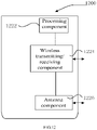
- FIG. 12 is a block diagram illustrating an apparatus for configuring a channel carrier according to an example.
- An apparatus 1200 may be provided as a base station. As shown in FIG. 12 , the apparatus 1200 includes a processing component 1222, a wireless transmission/receiving component 1224, an antenna component 1226, and a signal processing part specific to the wireless interface.
- the processing component 1222 may further include one or more processors.
- One of the processors in the processing component 1222 can be configured to:
- a non-transitory computer-readable storage medium storing instructions.
- the above instructions are executed by the processing component 1222 of the apparatus 1200 to perform the above method of the above second aspect, including: generating a message carrying channel carrier configuration information, where the channel carrier configuration information indicates numerology/TTI configuration information for a logical channel; and; sending the message to UE, where the message is configured for the UE to determine each carrier mapped to the logical channel and a numerology/TTI configured for each carrier mapped to the logical channel.
- the non-transitory computer readable storage medium may be a Read Only Memory (ROM), a Random Access Memory (RAM), a CD-ROM, a magnetic tape, a floppy disk, and an optical data storage device and so on.
Description
- The present disclosure relates to the field of communication technologies, and in particular to a method, an apparatus, for configuring a channel carrier, user equipment and a base station.
- In a research discussion of the 5th Generation (5G) mobile communication technology project, in order to support diversified service requirements, such as large bandwidth services, low-latency and high-reliability services, and small data packet services, a concept of multiple numerologies/transmission time interval (numerologies/TTI) durations is introduced in a physical layer. The multiple numerologies refer to that there are a plurality of supported sub-carrier intervals. The multiple TTI durations refer to that there are a plurality of time lengths of supported TTIs.
- In the related art, a logical channel may be mapped to one or more numerologies/TTI durations in a Radio Resource Control (RRC) message. In the configuration manner of the related art, user equipment (UE) in a multi-carrier communication, when allocating uplink resources of a particular carrier to a logical channel, may obtain a numerology/TTI duration configuration with a low priority for the logical channel, thereby reducing efficiency of service transmission. Additionally, in the related art, a configuration manner of mapping the logical channel to one or more numerologies/TTI durations by using the RRC message has low flexibility and long latency. Further, since UE in an inactive state does not perform cell handover during movement, the UE in the inactive state cannot determine the numerology/TTI duration configuration in time when moving to and residing in another cell which is adopting a different carrier.
- Samsung: "HARQ-ACK Feedback for Numerology Multiplexing", 3GPP DRAFT; R1-1705402, considered aspects for CA operation among NR cells with different slot durations and for numerology multiplexing within a single carrier. R1-1705402 discloses that logical channel to numerology/TTI length mapping can be reconfigured via RRC reconfiguration.
- Huawei et al: "Redundancy Schemes below PDCP Layer", 3GPP DRAFT; R2-1701201, analyses the detailed redundancy schemes in RLC and MAC layers, respectively. R2-1701201 discloses that logical channel to numerology/TTI length mapping can be reconfigured via RRC reconfiguration. R2-1701201 also discloses that hence when the single logical channel is allowed to be mapped to multiple numerology/TTI duration, it makes sense to allow that duplication could be transmitted over multiple numerologies either in a single carrier or multiple carriers.
- Huawei et al: "LCP with Multiple Numerologies", 3GPP DRAFT; R2-1702602, analyses logical channel multiplexing schemes to support the introduction of multiple numerologies. R2-1702602 discloses that logical channel to numerology/TTI length mapping can be reconfigured via RRC reconfiguration. R2-1702602 also discloses that the network or the gNB can provide differentiated QoS to different logical channel via mapping between the logical channel and the numerology/TTI, and giving those logical channels proper priorities.
-
EP 3 576 480 A1 is comprised in the state of the art relevant to the question of novelty, it discloses a method for use in a wireless communication system as well as a related wireless device. In accordance with one embodiment the method includes receiving, by the wireless device, configuration parameters of logical channels grouped into logical channel groups comprising a first logical channel group. The method ofEP 3 576 480 A1 further includes transmitting a truncated buffer status report (BSR) based on a number of padding bits. The truncated BSR comprises a presence bit indicating a presence of a buffer size field for the first logical channel group as well as a first number of buffer size fields for logical channel groups with logical channels having data for transmission following a decreasing order of priority. The first number is determined based on the number of padding bits. Furthermore, a corresponding method for a base station and a respective base station are described. -
WO 2018/128431 A1 is comprised in the state of the art relevant to the question of novelty, it discloses that a user equipment (UE) receives first configuration information for one or more numerology sets, each numerology set including one or more numerologies. The UE receives second configuration information for one or more logical channels, each logical channel mapped to one or more numerologies. The UE receives a first uplink (UL) grant for new transmission, the first UL grant including information indicating a numerology set associated with the first UL grant. The UE generates a MAC PDU. The UE performs a new transmission of the MAC PDU using the first UL grant. The MAC PDU contains data from a logical channel of which every numerology belongs to the numerology set. -
WO 2016/163663 A1 discloses a method and a device for performing a LCP procedure in a carrier aggregation, the method comprising: configuring with a first cell group including at least one first cell and a second cell group including at least one second cell served by an eNB; configuring two or more logical channels, wherein each of the two or more logical channels has - respective logical channel priority for a LCP procedure; receiving a UL grant from the first cell or the second cell; performing a LCP procedure to the two or more logical channels in decreasing priority order when the UL grant is received from the first cell; and performing a LCP procedure to the two or more logical channels in increasing priority order when the UL grant is received from the second cell.
- To overcome the problems existing in the related art, examples of the present disclosure provides a method and an apparatus for configuring a channel carrier, user equipment and a base station.
- According to a first aspect of an example of the present disclosure, a method of configuring a channel carrier by a user equipment is provided as defined by claim 1.
- According to a second aspect of an example of the present disclosure, a method of configuring a channel carrier by a base station is provided as defined by claim 5.
- According to a third aspect of an example of the present disclosure, an apparatus for configuring a channel carrier for a user equipment provided as defined by claim 8.
- According to a fourth aspect of an example of the present disclosure, an apparatus for configuring a channel carrier is provided as defined by
claim 9. - The technical solutions of the examples of the present disclosure may have the following beneficial effects.
- The accompanying drawings, which are incorporated in and constitute a part of this specification, illustrate examples consistent with the present disclosure and, together with the description, serve to explain the principles of the disclosure.
-
FIG. 1A is a flow chart illustrating a method of configuring a channel carrier according to an example. -
FIG. 1B is a scenario diagram illustrating a method of configuring a channel carrier according to an example. -
FIG. 2 is a flow chart illustrating another method of configuring a channel carrier according to an example. -
FIG. 3A is a flow chart 1 illustrating still another method of configuring a channel carrier according to an example. -
FIG. 3B is a flow chart 2 illustrating still another method of configuring a channel carrier according to an example. -
FIG. 4 is a flow chart illustrating yet another method of configuring a channel carrier according to an example. -
FIG. 5 is a flow chart illustrating a method of configuring a channel carrier according to an example. -
FIG. 6 is a flow chart illustrating another method of configuring a channel carrier according to an example. -
FIG. 7 is a block diagram illustrating an apparatus for configuring a channel carrier according to an example. -
FIG. 8 is a block diagram illustrating another apparatus for configuring a channel carrier according to an example. -
FIG. 9 is a block diagram illustrating an apparatus for configuring a channel carrier according to an example. -
FIG. 10 is a block diagram illustrating another apparatus for configuring a channel carrier according to an example. -
FIG. 11 is a block diagram illustrating an apparatus suitable for configuring a channel carrier according to an example. -
FIG. 12 is a block diagram illustrating an apparatus suitable for configuring a channel carrier according to an example. - Examples will be described in detail herein, with the illustrations thereof represented in the drawings. When the following descriptions involve the drawings, like numerals in different drawings refer to like or similar elements unless otherwise indicated. The embodiments described in the following examples do not represent all embodiments consistent with the present disclosure. Rather, they are merely examples of apparatuses and methods consistent with some aspects of the present disclosure as detailed in the appended claims.
-
FIG. 1A is a flow chart illustrating a method of configuring a channel carrier according to an example.FIG. 1B is a scenario diagram illustrating a method of configuring a channel carrier according to an example. The method of configuring a channel carrier may be applied to UE. As shown inFIG. 1A , the method of configuring a channel carrier may include the following blocks 101-102. - At
block 101, a message carrying channel carrier configuration information sent by a base station is received, where the channel carrier configuration information indicates numerology/transmission time interval configuration information for a logical channel. - In an example, the numerology may be understood as a set of parameters used by a communication system. For example, the numerology may include a sub-carrier spacing (SCS), a symbol length, a cyclic prefix (CP) length, and so on. For different numerologies, the parameter values may also be different. For example, the SCS is set to 15∗(2^n) kHz, where n may be a negative number. That is, the SCS may be set to 3.75kHz, 7.5kHz, 15kHz, 30kHz, 60kHz, 120kHz and so on. The other parameters may also be set to a variable value.
- In an example, there may be a plurality of Transmission Time Interval (TTI) durations, for example, a TTI duration may be two symbols, four symbols, eight symbols, one sub-frame, a plurality of sub-frames or the like.
- In an example, the channel carrier configuration information may be numerology/TTI configuration information for a logical channel. Because there is a situation with multiple carriers, the logical channel and the carriers may be firstly bound and then a corresponding numerology/TTI is configured for the bound carrier. For example, logical channel 1 is bound with carrier 1 and carrier 2, the carrier 1 is configured with numerology 1/TTI 1, and the carrier 2 is configured with numerology 2/TTI 2. Thus, the numerology/TTI is configured for the logical channel in a distinguishing carrier manner.
- In an example, the message may be an RRC message, such as a connection reconfiguration message, a cell handover message, or the like. The channel carrier configuration information may be added in an encapsulation header of an RRC layer in the RRC message, so as to perform channel carrier configuration for the UE accessing an RRC connection.
- In an example, a channel carrier configuration flow with the message being the RRC message may be refer to the example shown in
FIG. 2 . - In an example, the message may be a general message with an unlimited type, such as a system message, a service data message, or the like. The message may also be an RRC message. The channel carrier configuration information may be added to a Media Access Control (MAC) control element in a MAC layer Protocol Data Unit (PDU), so as to update a channel carrier configuration stored in the UE. A modification latency may be reduced by carrying the channel carrier configuration information in the MAC control element. In an example, when the message carries the channel carrier configuration information through the MAC control element, the channel carrier configuration information may only include a carrier or a carrier list corresponding to the logical channel; or only include a numerology/TTI configured for one or more carriers associated with the logical channel.
- In an example, a channel carrier configuration flow may be referred to the examples shown in
FIG. 3A and FIG. 3B , which the message is a general message and the channel carrier configuration information is carried through the MAC control element. - At
block 102, based on the channel carrier configuration information, each carrier mapped to the logical channel and a numerology/TTI configured for each carrier mapped to the logical channel are determined. - In an example, a reference may be made to the example shown in
FIG. 2 for a flow of determining each carrier mapped to the logical channel and the numerology/TTI configured for each carrier mapped to the logical channel based on the channel carrier configuration information in the RRC message. - In an example, a reference may be made to the examples shown in
FIGs. 3A and 3B for a flow of determining each carrier mapped to the logical channel and the numerology/TTI configured for each carrier mapped to the logical channel based on the channel carrier configuration information in the MAC control element of the general message. - In an exemplary scenario, as shown in
FIG. 1B , illustrative descriptions are made with a mobile network as a 5G network and a base station as gNB (a 5G base station). The scenario shown inFIG. 1B includes gNB 10 andUE 20.gNB 10 may indicate channel carrier configuration information to UE through a message. After receiving the message carrying the channel carrier configuration information,UE 20 may configure a logical channel and a numerology/TTI per carrier, that is, in a distinguishing carrier manner. Further, when the channel carrier configuration ofUE 20 is to be updated,gNB 10 may directly send new channel carrier configuration information through a MAC control element in a message of any type. In this way, problems of low flexibility and long latency caused by a configuring manner of mapping the logical channel to one or more numerologies/TTIs only using an RRC message are avoided. - Through the above blocks 101-102, each logical channel may be mapped to corresponding carrier(s), and a corresponding numerology/TTI is configured for a carrier mapped to the logical channel. Thus, the logical channel and the numerology/TTI are configured in a distinguishing carrier manner. Further, by carrying the channel carrier configuration information in the MAC control element, problems of low flexibility and long latency caused by a configuring manner of mapping the logical channel to one or more numerologies/TTIs only using the RRC message are avoided.
- In an example, receiving the message carrying the channel carrier configuration information sent by the base station includes:
receiving an RRC message carrying the channel carrier configuration information sent by the base station. - In an example, determining each carrier mapped to the logical channel and the numerology/TTI configured for each carrier mapped to the logical channel based on the channel carrier configuration information includes:
analyzing each carrier mapped to the logical channel and the numerology/TTI configured for each carrier mapped to the logical channel from the RRC message. - In an example, when the RRC message is an RRC message instructing the UE to switch to an inactive state, the RRC message further carries respective numerologies/TTIs configured for different carriers associated with the logical channel.
- The method of configuring a channel carrier further includes: determining a carrier for a cell when the UE in the inactive state resides in the cell; and
determining the numerology/TTI configured for the carrier of the cell with respect to the logical channel based on the carrier of the cell. - In an example, when the RRC message is an RRC message instructing the UE to switch to an inactive state, the RRC message further carries respective numerologies/TTIs configured for different carriers and different cells associated with the logical channel.
- The method of configuring a channel carrier further includes: determining a carrier for a cell and identification information of the cell when the UE in the inactive state resides in the cell; and
determining a numerology/transmission time interval configured for the carrier for the cell with respect to the logical channel, based on the carrier for the cell and the identification information of the cell. - In an example, receiving the message carrying the channel carrier configuration information sent by the base station includes:
receiving the message with the channel carrier configuration information carried in a MAC control element sent by the base station. - In an example, determining each carrier mapped to the logical channel and the numerology/TTI configured for each carrier mapped to the logical channel based on the channel carrier configuration information includes:
- Obtaining each carrier to which the logical channel is to be mapped by analyzing contents of the MAC control element from a MAC protocol data unit in the message; and
updating the carrier mapped to the logical channel based on the carrier to which the logical channel is to be mapped. - In an example, determining each carrier mapped to the logical channel and the numerology/TTI configured for each carrier mapped to the logical channel based on the channel carrier configuration information includes:
- obtaining the numerology/TTI configured for each carrier mapped to the logical channel by analyzing contents of the MAC control element from a MAC protocol data unit of the message; and
- updating the numerology/TTI configured for each carrier mapped to the logical channel based on the numerology/TTI to be configured for each carrier.
- In an example, the method of configuring a channel carrier further includes:
- receiving an uplink (UL) grant message sent by the base station;
- analyzing the UL grant message to obtain an allocated carrier and a numerology/TTI configured for the allocated carrier; and
- determining uplink resource allocation information based on the allocated carrier, the numerology/transmission time interval configured for the allocated carrier, a locally-stored carrier mapped to the logical channel, and a locally-stored numerology/transmission time interval configured for each carrier mapped to the logical channel.
- A reference may be made to the subsequent examples for how to configure a channel carrier.
- Thus, the methods provided by examples of the present disclosure may configure the logical channel and the numerology/TTI in a distinguishing carrier manner. When updating the channel carrier configuration of the UE, the channel carrier configuration information carried in the MAC control element may be used. Thus, flexibility of updating configuration is improved and latency is reduced.
- The technical solutions of the examples of the present disclosure will be described below with specific examples.
-
FIG. 2 is a flow chart illustrating another method of configuring a channel carrier according to an example. According to the above method of the examples of the present disclosure, illustrative descriptions are made to a flow of configuring a channel carrier with a message as an RRC message. As shown inFIG. 2 , the following blocks are included. - At
block 201, an RRC message carrying channel carrier configuration information sent by a base station is received. - In an example, the RRC message may be a connection reconfiguration message, a cell handover instruction, a state switching message and so on. The base station may add the channel carrier configuration information in an RRC layer. The channel carrier configuration information in the RRC message may include each carrier bound with a logical channel and a numerology/TTI configured for each carrier bound with the logical channel.
- At
block 202, each carrier mapped to the logical channel and a numerology/TTI configured for each carrier mapped to the logical channel are analyzed from the RRC message. - In an example, each carrier mapped to the logical channel and the numerology/TTI configured for each carrier mapped to the logical channel may be analyzed in an encapsulation header of an RRC layer in the RRC message.
- In an example, when the RRC message is an RRC message instructing the UE to switch to an inactive state, the method further includes
blocks - At
block 203, a carrier for a cell is determined when the UE in an inactive state resides in the cell. - At
block 204, a numerology/TTI configured for the carrier for the cell with respect to the logical channel is determined based on the carrier for the cell. - In an example, at
blocks - In an example, when the RRC message is an RRC message instructing the UE to switch to an inactive state, the method further includes
blocks - At
block 205, when the UE in the inactive state resides in a cell, a carrier for the cell and identification information of the cell are determined. - At
block 206, the numerology/TTI configured for the carrier of the cell with respect to the logical channel is determined based on the carrier for the cell and the identification information of the cell. - In an example, at
blocks - In the example, for the UE instructed to switch to the inactive state, the corresponding RRC message for instructing the switch may carry channel carrier configuration information associated with another cell. After the UE switches to the inactive state and resides in the another cell, the UE in the inactive state may still determine the configuration of the numerology/TTI.
-
FIG. 3A is a flow chart 1 illustrating still another method of configuring a channel carrier according to an example.FIG. 3B is a flow chart 2 illustrating still another method of configuring a channel carrier according to an example. According to the above methods of the examples of the present disclosure, illustrative descriptions are made to a flow of configuring a channel carrier, in which the message is a message with channel carrier configuration information carried in a MAC control element. As shown inFIG. 3A , the method may include the following blocks. - At
block 301, a message with channel carrier configuration information carried in a MAC control element sent by a base station is received. - In an example, the message with the channel carrier configuration information carried in the MAC control element may be a service data message, a system message, or the like. The type of the message with the channel carrier configuration information carried in the MAC control element is not limited in the present disclosure.
- At
block 302, each to-be-mapped carrier for a logical channel is obtained by analyzing contents in the MAC control element of a MAC protocol data unit of the message. - In an example, the MAC control element may only carry each to-be-mapped carrier for the logical channel, and the to-be-mapped carrier may be more than one carrier. For example, if a channel carrier configuration is logical channel 1 being mapped to carrier 1, carrier 2 and carrier 3, where the channel carrier configuration is configured for a data radio bearer (DRB) in an RRC configuration, in the subsequent MAC control element, the carrier mapped to logical channel 1 may be updated to any one of carrier 1, carrier 2 and carrier 3, or a combination of any two.
- In an example, if original mapped carrier(s) associated with a logical channel do not include the carrier mapped to the logical channel in the MAC control element, the MAC control element is required to further carry a numerology/TTI of a newly-added carrier. For example, assuming that a channel carrier configuration is logical channel 1 being mapped to carrier 1 and carrier 2, where the channel carrier configuration is configured for a DRB in an RRC configuration. In this case, when the carrier mapped to logical channel 1 is to be updated to carrier 3 in the MAC control element, it is to analyze the numerology/TTI configured for carrier 3 in the MAC control element, where carrier 3 is mapped to logical channel 1.
- At
block 303, carrier mapped to the logical channel is updated based on the to-be-mapped carrier. - In an example, if the MAC control element carries the numerology/TTI configured for each carrier mapped to the logical channel, the following blocks may be included based on the channel carrier configuration method shown in
FIG. 3B . - At
block 311, the numerology/TTI configured for each carrier mapped to the logical channel is obtained by analyzing contents in the MAC control element within the MAC protocol data unit of the message. - At
block 312, each carrier to which the logical channel is to be mapped, is obtained by analyzing the contents in the MAC control element within the MAC protocol data unit of the message. - At
block 313, a numerology/TTI configured for each carrier mapped to the logical channel is updated based on a numerology/TTI to be configured for each carrier. - In an example, the MAC control element may carry a new numerology/TTI configured for each carrier mapped to the logical channel. For example, if a channel carrier configuration is logical channel 1 being mapped to carrier 1 and carrier 2, where the channel carrier configuration is configured for a DRB in an RRC configuration, numerologies/TTIs configured for carrier 1 is numerology 1/TTI 1 and numerology 2/TTI 2. In this case, when a numerology/TTI for carrier 1 bound with logical channel 1 is set to numerology 1/TTI 1 in the MAC control element, the numerology/TTI for carrier 1 bound with logical channel 1 may be updated to numerology 1/TTI 1.
- In an example, when receiving the message with the channel carrier configuration information carried in the MAC control element, the UE may update the channel carrier configuration in time. Problems of low flexibility and long latency caused by a configuring manner of mapping the logical channel to one or more numerologies/TTIs only using the RRC message are avoided.
- In this example, all pieces of UE may receive to-be-requested system information by receiving the to-be-requested system information sent on a physical downlink shared channel based on a system information scheduling instruction within a receiving window period. In this way, multiple pieces of UE may multiplex the to-be-requested system information sent by the base station, thereby improving the sending and receiving performances of the system information.
-
FIG. 4 is a flow chart illustrating yet another method of configuring a channel carrier according to an example. According to the above methods of examples of the present disclosure, illustrative descriptions are made to a flow of allocating, by UE, an uplink resource to a logical channel upon receiving a UL grant message. As shown inFIG. 4 , the following blocks are included. - At
block 401, an uplink (UL) grant message sent by a base station is received. - In an example, when receiving a scheduling message for allocating radio resources from the base station, e.g., the UL grant message, UE can determine in which time domain and on which carrier data is transmitted, and an adopted modulation and coding scheme.
- At
block 402, an allocated carrier and a numerology/TTI configured for the allocated carrier are obtained by analyzing the UL grant message. - At
block 403, uplink resource allocation information is determined based on the allocated carrier, the numerology/TTI configured for the allocated carrier, a locally-stored carrier mapped to the logical channel, and a locally-stored numerology/TTI configured for each carrier mapped to the logical channel. - In an example, at blocks 401-403, the UL grant message further carries the numerology/TTI configured for the carrier. For example, the UE may be granted to transmit data on carrier 1 based on numerology 1/TTI 1. In this case, the UE may firstly determine that a logical channel is bound with carrier 1. If logical channel 1 is bound with carrier 1, it is further determined, in the UL grant message, the uplink resource which is included the numerology/TTI configured for carrier 1 bound with logical channel 1. If the uplink resource exists and is not allocated out yet, the uplink resource may be allocated for the logical channel 1.
- In an example, if the UE receives a message carrying the channel carrier configuration information during a process of using the uplink resource, the allocation of the uplink resource is performed still based on an original channel carrier configuration for a UL grant received before the message carrying the channel carrier configuration information is received; and the allocation of the uplink resource is performed based on an updated channel carrier configuration for a UL grant received after the message carrying the channel carrier configuration information is received.
- In the example, after receiving the UL grant message, the UE may perform allocation for the uplink resource based on the carrier and the numerology/TTI configured for the carrier, thereby realizing an optimal result of resource allocation.
-
FIG. 5 is a flow chart illustrating a method of configuring a channel carrier according to an example, which may be applied to a base station. This example will be described illustratively in combination withFIG. 1B . As shown inFIG. 1B , the method of configuring a channel carrier may include the following blocks 501-502. - At
block 501, a message carrying channel carrier configuration information is generated, where the channel carrier configuration information indicates numerology/TTI configuration information for a logical channel. - In an example, for an RRC message, the channel carrier configuration information includes information on each carrier mapped to the logical channel and information on a numerology/TTI configured for each carrier mapped to the logical channel. In an example, for a message instructing UE to switch to an inactive state, the channel carrier configuration information further includes respective numerologies/TTIs configured for different carriers associated with the logical channel, or respective numerologies/TTIs configured for different carriers and different cells associated with the logical channel. In an example, for the RRC message, the channel carrier configuration information may be added in an encapsulation header of an RRC layer.
- In an example, when the message is not the RRC message, the channel carrier configuration information may include each to-be-mapped carrier for the logical channel, and/or, a numerology/TTI configured for each carrier mapped to the logical channel. In an example, when the message is not the RRC message, the channel carrier configuration information may be added in a MAC control element.
- At
block 502, the message is sent to the UE, where the message is used for the UE to determine each carrier mapped to the logical channel and a numerology/TTI configured for each carrier mapped to the logical channel. - In an exemplary scenario, as shown in
FIG. 1B , illustrative descriptions are made with a mobile network as a 5G network and a base station as gNB (a 5G base station). The scenario shown inFIG. 1B includes gNB 10 andUE 20.gNB 10 may indicate channel carrier configuration information to UE through a message. After receiving the message carrying the channel carrier configuration information,UE 20 may configure a logical channel and a numerology/TTI per carrier, that is, in a distinguishing carrier manner. Further, when the channel carrier configuration ofUE 20 is to be updated,gNB 10 may directly send new channel carrier configuration information through a MAC control element in a message of any type. In this way, problems of low flexibility and long latency caused by a configuring manner of mapping the logical channel to one or more numerologies/TTIs only using the RRC message are avoided. - In an example, through the above blocks 501-502, each logical channel may be mapped to corresponding carrier(s), and a corresponding numerology/TTI is configured for each carrier mapped to the logical channel. Thus, the logical channel and the numerology/TTI are configured in a distinguishing carrier manner. Further, by carrying the channel carrier configuration information in the MAC control element, problems of low flexibility and long latency caused by a configuring manner of mapping the logical channel to one or more numerologies/TTIs only using the RRC message are avoided.
- In the example, when the message is an RRC message, the channel carrier configuration information includes information on each carrier mapped to the logical channel and information on the numerology/TTI configured for each carrier mapped to the logical channel.
- In an example, when the RRC message is a message instructing the UE to switch to an inactive state, the RRC message further carries the respective numerologies/TTIs configured for different carriers associated with the logical channel; or respective numerologies/TTIs configured for different carriers and different cells associated with the logical channel.
- In an example, when the message is not an RRC message, generating the message carrying the channel carrier configuration information includes:
obtaining the message by adding the channel carrier configuration information to a MAC control element of the message. - In an example, the channel carrier configuration information includes information on each carrier to which the logical channel is to be mapped and/or information on the numerology/transmission time interval configured for each carrier mapped to the logical channel.
- In an example, the method of configuring a channel carrier further includes:
- generating a UL grant message, where the UL message carries a carrier allocated to the UE and a numerology/TTI configured for the carrier; and
- sending the UL grant message to the UE.
- Technical solutions of the present disclosure will be described below with specific examples.
-
FIG. 6 is a flow chart illustrating another method of configuring a channel carrier according to an example. According to the above methods of the examples of the present disclosure, illustrative descriptions are made with how to instruct allocating an uplink resource to UE. As shown inFIG. 6 , the following blocks are included. - At
block 601, an uplink grant scheduling message is generated, where the uplink grant scheduling message carries a carrier allocated to the UE and a numerology/TTI configured for the carrier. - In an example, gNB should firstly know quality of an uplink channel before allocating the uplink resource to the UE. Upon the uplink channel of the UE has good quality and the UE has a requirement of data transmission, the gNB may allocate a resource to the UE.
- In an example, when the base station allocates the resource to the UE based on the uplink channel quality of the UE, the carrier allocated to the UE and the numerology/TTI configured for the carrier may be added in a UL grant message, so as to generate the UL grant message. For example, UE may be granted to transmit data on carrier 1 based on numerology 1/TTI 1.
- At
block 602, the uplink grant scheduling message is sent to the UE. - In an example, the base station may add the carrier allocated to the UE and the numerology/TTI configured for the carrier in the UL grant message, and send the UL grant message to the UE, so that the UE may allocate the uplink resource based on the carrier and the configured numerology/TTI, thereby realizing an optimal result of resource allocation.
-
FIG. 7 is a block diagram illustrating an apparatus for configuring a channel carrier according to an example. As shown inFIG. 7 , the apparatus for configuring a channel carrier includes: - a
first receiving module 710, configured to receive a message carrying channel carrier configuration information sent by a base station, where the channel carrier configuration information indicates numerology/TTI configuration information for a logical channel; and - a
first configuring module 720, configured to determine each carrier mapped to the logical channel and a numerology/TTI configured for each carrier mapped to the logical channel, based on the channel carrier configuration information carried in the message received by thefirst receiving module 710. -
FIG. 8 is a block diagram illustrating another apparatus for configuring a channel carrier according to an example. In an example, as shown inFIG. 8 , based on the example ofFIG. 7 , thefirst receiving module 710 may include:
a first receivingsub-module 711, configured to receive an RRC message carrying the channel carrier configuration information sent by the base station. - In an example, the
first configuring module 720 includes:
a first analyzingsub-module 721, configured to analyze, from the RRC message, the carriers mapped to each logical channel and the numerology/TTI configured for each carrier mapped to the logical channel. - In an example, when the RRC message is an RRC message instructing user equipment to switch to an inactive state, the RRC message further carries respective numerologies/TTIs configured for different carriers associated with the logical channel;
the apparatus further includes: - a first determining
module 730, configured to determine a carrier for a cell when the user equipment in the inactive state resides in the cell; and - a second determining
module 740, configured to determine a numerology/TTI configured for the carrier for the cell with respect to the logical channel, based on the carrier for the cell which is determined by the first determiningmodule 730. - In an example, when the RRC message is the RRC message instructing the user equipment to switch to the inactive state, the RRC message further carries respective numerologies/TTIs configured for different carriers and different cells associated with the logical channel; and
the apparatus further includes: - a third determining
module 750, configured to determine a carrier for a cell and identification information of the cell when the user equipment in the inactive state resides in the cell; and - a fourth determining
module 760, configured to determine a numerology/TTI configured for the carrier for the cell with respect to the logical channel, based on the carrier for the cell and the identification information of the cell which are determined by the third determiningmodule 750. - In an example, the
first receiving module 710 includes:
a second receiving sub-module 712, configured to receive the message, sent by the base station, with the channel carrier configuration information carried in a MAC control element. - In an example, the
first configuring module 720 includes: - a
second analyzing sub-module 722, configured to obtain each carrier to which the logical channel is to be mapped, by analyzing contents of the MAC control element from a MAC protocol data unit in the message; and - a first updating
sub-module 723, configured to update the carrier mapped to the logical channel based on the carrier to which the logical channel is to be mapped, obtained by the second analyzing sub-module. - In an example, the
first configuring module 720 includes: - a third analyzing sub-module 724, configured to obtain the numerology/TTI configured for each carrier mapped to the logical channel, by analyzing contents of the MAC control element from a MAC protocol data unit of the message; and
- a
second updating sub-module 725, configured to update the numerology/TTI configured for each carrier mapped to the logical channel, based on the numerology/TTI to be configured for each carrier which is obtained by the third analyzingsub-module 724. - In an example, the apparatus further includes:
- a
second receiving module 770, configured to receive a UL grant message sent by the base station; - an
analyzing module 780, configured to analyze, from the UL grant message received by thesecond receiving module 770, an allocated carrier and a numerology/TTI configured for the allocated carrier; and - a fifth determining
module 790, configured to determine uplink resource allocation information based on the allocated carrier obtained by the analyzingmodule 780, the numerology/TTI configured for the allocated carrier obtained by the analyzingmodule 780, a locally-stored carrier mapped to the logical channel, and a locally-stored numerology/TTI configured for each carrier mapped to the logical channel. -
FIG. 9 is a block diagram illustrating an apparatus for configuring a channel carrier according to an example of the present disclosure. As shown inFIG. 9 , the apparatus for configuring a channel carrier includes: - a
first generating module 910, configured to generate a message carrying channel carrier configuration information, where the channel carrier configuration information indicates numerology/TTI configuration information for a logical channel; and - a
first sending module 920, configured to send the message generated by thefirst generating module 910 to user equipment, where the message is configured for the user equipment to determine each carrier mapped to the logical channel and a numerology/TTI configured for each carrier mapped to the logical channel. -
FIG. 10 is a block diagram illustrating another apparatus for configuring a channel carrier according to an example of the present disclosure. In an example, as shown inFIG. 10 , on the basis of the example ofFIG. 9 , when the message is an RRC message, the channel carrier configuration information includes information on each carrier mapped to the logical channel and information on the numerology/TTI configured for each carrier mapped to the logical channel. - In an example, when the RRC message is an RRC message instructing the user equipment to switch to an inactive state, the RRC message further carries respective numerologies/TTIs configured for different carriers associated with the logical channel, or respective numerologies/TTIs configured for different carriers and different cells associated with the logical channel.
- In an example, when the message is not the RRC message, the
first generating module 910 includes:
a generating sub-module 911, configured to obtain the message by adding the channel carrier configuration information to a MAC control element of the message. - In an example, the channel carrier configuration information includes information on each carrier to which the logical channel is to be mapped and/or information on the numerology/TTI configured for each carrier mapped to the logical channel.
- In an example, the apparatus further includes:
- a
second generating module 930, configured to generate a UL grant message, where the UL grant message carries a carrier allocated to the user equipment and a numerology/TTI configured for the allocated carrier; and - a
second sending module 940, configured to send the UL grant message generated by thesecond generating module 930 to the user equipment. - The specific manners in which different modules of the apparatus of the above examples perform operation are already described in detail in the examples of relevant method, which will not be repeated here.
-
FIG. 11 is a block diagram illustrating an apparatus for configuring a channel carrier according to an example. For example, anapparatus 1100 may be user equipment, such as a mobile phone, a computer, a digital broadcast terminal, a message transceiver, a game console, a tablet device, a medical device, a fitness device, a personal digital assistant, and so on. - As shown in
FIG. 11 , theapparatus 1100 may include one or more of the following components: aprocessing component 1102, amemory 1104, apower supply component 1106, amultimedia component 1108, anaudio component 1110, an input/output (I/O)interface 1112, asensor component 1114 and acommunication component 1116. - The
processing component 1102 generally controls overall operations of theapparatus 1100, such as operations associated with display, phone calls, data communications, camera operations, and recording operations. Theprocessing component 1102 may include one ormore processors 1120 for executing instructions to complete all or a part of steps of the above method. In addition, theprocessing component 1102 may include one or more modules which facilitate the interaction between theprocessing component 1102 and other components. For example, theprocessing component 1102 may include a multimedia module to facilitate the interaction between themultimedia component 1108 and theprocessing component 1102. - The
memory 1104 may be configured to store various types of data to support the operation of theapparatus 1100. Examples of such data include instructions for any application or method operated on theapparatus 1100, contact data, phonebook data, messages, pictures, videos, and so on. Thememory 1104 may be implemented by any type of volatile or non-volatile memory devices or a combination thereof, such as a Static Random Access Memory (SRAM), an Electrically Erasable Programmable Read-Only Memory (EEPROM), an Erasable Programmable Read-Only Memory (EPROM), a Programmable Read-Only Memory (PROM), a Read-Only Memory (ROM), a magnetic memory, a flash memory, a magnetic, or compact disk. - The
power supply component 1106 may provide power to different components of theapparatus 1100. Thepower supply component 1106 may include a power management system, one or more power supplies and other components associated with generating, managing, and distributing power for theapparatus 1100. - The
multimedia component 1108 may include a screen providing an output interface between theapparatus 1100 and a user. In some examples, the screen may include a Liquid Crystal Display (LCD) and a Touch Panel (TP). If the screen includes the TP, the screen may be implemented as a touch screen to receive input signals from the user. The TP may include one or more touch sensors to sense touches, swipes, and gestures on the TP. The touch sensors may not only sense a boundary of a touch or swipe, but also sense a duration and a pressure associated with the touch or swipe. In some examples, themultimedia component 1108 may include a front camera and/or a rear camera. The front camera and/or rear camera may receive external multimedia data when theapparatus 1100 is in an operating mode, such as a photographing mode or a video mode. Each of the front camera and the rear camera may be a fixed optical lens system or have focal length and optical zooming capability. - The
audio component 1110 may be configured to output and/or input an audio signal. For example, theaudio component 1110 may include a microphone (MIC) configured to receive an external audio signal when theapparatus 1100 is in an operating mode, such as a call mode, a recording mode, and a voice recognition mode. The received audio signal may be further stored in thememory 1104 or sent via thecommunication component 1116. In some examples, theaudio component 1110 further includes a speaker to output an audio signal. - The I/
O interface 1112 provides interfaces between theprocessing component 1102 and peripheral interface modules. The above peripheral interface modules may be a keyboard, a click wheel, buttons, and so on. These buttons may include, but are not limited to, a home button, a volume button, a starting button, and a locking button. - The
sensor component 1114 may include one or more sensors to provide status assessments of various aspects for theapparatus 1100. For example, thesensor component 1114 may detect an on/off state of theapparatus 1100, and relative positioning of an component, for example, the component is a display and a mini-keypad of theapparatus 1100. Thesensor component 1114 may also detect a change in position of theapparatus 1100 or a component of theapparatus 1100, a presence or absence of the contact between a user and theapparatus 1100, an orientation or an acceleration/deceleration of theapparatus 1100, and a change in temperature of theapparatus 1100. Thesensor component 1114 may include a proximity sensor configured to detect the presence of a nearby object without any physical contact. Thesensor component 1114 may further include an optical sensor, such as a CMOS or CCD image sensor which is used in imaging applications. In some examples, thesensor component 1114 may further include an acceleration sensor, a gyroscope sensor, a magnetic sensor, a pressure sensor, or a temperature sensor. - The
communication component 1116 may be configured to facilitate wired or wireless communication between theapparatus 1100 and other devices. Theapparatus 1100 may access a wireless network that is based on a communication standard, such as Wi-Fi, 2G, 3G or a combination thereof. In an example, thecommunication component 1116 receives broadcast signals or broadcast-associated information from an external broadcast management system via a broadcast channel. In an example, thecommunication component 1116 further includes a Near Field Communication (NFC) module to facilitate short-range communications. For example, the NFC module may be implemented based on a Radio Frequency Identification (RFID) technology, an Infrared Data Association (IrDA) technology, an Ultra Wideband (UWB) technology, a Bluetooth® (BT) technology and other technologies. - In an example, the
apparatus 1100 may be implemented by one or more application specific integrated circuits (ASIC), digital signal processors (DSP), digital signal processing devices (DSPD), programmable logic devices (PLD), field programmable gate arrays (FPGA), controllers, microcontrollers, microprocessors or other electronic components for performing the method of the above first aspect. The method includes: receiving a message carrying channel carrier configuration information sent by a base station, where the channel carrier configuration information indicates numerology/TTI configuration information for a logical channel; and determining each carrier mapped to the logical channel and a numerology/TTI configured for each carrier mapped to the logical channel, based on the channel carrier configuration information. - In an example, there is further provided a non-transitory computer-readable storage medium storing instructions, for example, a
memory 1104 storing the instructions. The instructions are executed by theprocessor 1120 of theapparatus 1100 to perform the method of the above first aspect, including: receiving a message carrying channel carrier configuration information sent by a base station, where the channel carrier configuration information indicates numerology/TTI configuration information for a logical channel; and determining each carrier mapped to the logical channel and a numerology/TTI configured for each carrier mapped to the logical channel, based on the channel carrier configuration information. The non-transitory computer readable storage medium may be a Read Only Memory (ROM), a Random Access Memory (RAM), a CD-ROM, a magnetic tape, a floppy disk, and an optical data storage device and so on. -
FIG. 12 is a block diagram illustrating an apparatus for configuring a channel carrier according to an example. Anapparatus 1200 may be provided as a base station. As shown inFIG. 12 , theapparatus 1200 includes aprocessing component 1222, a wireless transmission/receiving component 1224, anantenna component 1226, and a signal processing part specific to the wireless interface. Theprocessing component 1222 may further include one or more processors. - One of the processors in the
processing component 1222 can be configured to: - generate a message carrying channel carrier configuration information, wherein the channel carrier configuration information indicates numerology/TTI configuration information for a logical channel; and
- send the message to UE, where the message is configured for the UE to determine each carrier mapped to the logical channel and a numerology/TTI configured for each carrier mapped to the logical channel.
- In an example, there is further provided a non-transitory computer-readable storage medium storing instructions. The above instructions are executed by the
processing component 1222 of theapparatus 1200 to perform the above method of the above second aspect, including: generating a message carrying channel carrier configuration information, where the channel carrier configuration information indicates numerology/TTI configuration information for a logical channel; and; sending the message to UE, where the message is configured for the UE to determine each carrier mapped to the logical channel and a numerology/TTI configured for each carrier mapped to the logical channel. The non-transitory computer readable storage medium may be a Read Only Memory (ROM), a Random Access Memory (RAM), a CD-ROM, a magnetic tape, a floppy disk, and an optical data storage device and so on. - Other implementations of the present disclosure will be apparent to those skilled in the art from consideration of the specification and practice of the present disclosure herein. The invention is solely defined by the appended claims 1-9.
Claims (9)
- A method of configuring a channel carrier by a user equipment, comprising:receiving a message carrying channel carrier configuration information sent by a base station, wherein the channel carrier configuration information indicates numerology and/or transmission time interval configuration information for a plurality of carriers associated with a logical channel; anddetermining each of the plurality of carriers mapped to the logical channel and a numerology and/or a transmission time interval configured for each of the plurality of carriers mapped to the logical channel, based on the channel carrier configuration information;wherein receiving the message carrying the channel carrier configuration information sent by the base station comprises:
receiving a Radio Resource Control, RRC, message carrying the channel carrier configuration information sent by the base station; andcharacterized in that,wherein when the RRC message is an RRC message instructing user equipment to switch to an inactive state, the RRC message further carries respective numerologies and/or transmission time intervals configured for the plurality of carriers associated with the logical channel; andthe method further comprises:determining a carrier for a cell when the user equipment in the inactive state resides in the cell; anddetermining a numerology and/or a transmission time interval configured for the carrier for the cell with respect to the logical channel, based on the carrier for the cell. - The method according to claim 1, wherein determining each of the plurality of carriers mapped to the logical channel and the numerology and/or the transmission time interval configured for each of the plurality of carriers mapped to the logical channel based on the channel carrier configuration information comprises:
analyzing each of the plurality of carriers mapped to the logical channel and the numerology and/or the transmission time interval configured for each of the plurality of carriers mapped to the logical channel, from the RRC message. - The method according to claim 1, wherein, when the RRC message is the RRC message instructing the user equipment to switch to the inactive state, the RRC message further carries respective numerologies and/or transmission time intervals configured for the plurality of carriers and different cells associated with the logical channel; and
the method further comprises:determining a carrier for a cell and identification information of the cell when the user equipment in the inactive state resides in the cell; anddetermining a numerology and/or a transmission time interval configured for the carrier for the cell with respect to the logical channel, based on the carrier for the cell and the identification information of the cell. - The method according to claim 1, further comprising:receiving an uplink, UL, grant message sent by the base station;analyzing, from the UL grant message, an allocated carrier and a numerology and/or a transmission time interval configured for the allocated carrier; anddetermining uplink resource allocation information based on the allocated carrier, the numerology and/or the transmission time interval configured for the allocated carrier, a locally-stored carrier mapped to the logical channel, and a locally-stored numerology and/or a locally-stored transmission time interval configured for each of the plurality of carriers mapped to the logical channel.
- A method of configuring a channel carrier by a base station, comprising:generating a message carrying channel carrier configuration information, wherein the channel carrier configuration information indicates numerology and/or transmission time interval configuration information for a plurality of carriers associated with a logical channel; andsending the message to user equipment, wherein the message is configured for the user equipment to determine each of the plurality of carriers mapped to the logical channel and a numerology and/or a transmission time interval configured for each of the plurality of carriers mapped to the logical channel;wherein generating the message carrying the channel carrier configuration information comprises:generating a Radio Resource Control, RRC, message carrying the channel carrier configuration information; andcharacterized in that,when the RRC message is an RRC message instructing user equipment to switch to an inactive state, the RRC message further carries respective numerologies and/or transmission time intervals configured for the plurality of carriers associated with the logical channel; andwherein the message is further configured for the user equipment to determine a carrier for a cell when the user equipment in the inactive state resides in the cell, and to determine a numerology and/or a transmission time interval configured for the carrier for the cell with respect to the logical channel, based on the carrier for the cell.
- The method according to claim 5, wherein, when the message is the RRC message, the channel carrier configuration information further comprises:
information on each of the plurality of carriers mapped to the logical channel and information on the numerology and/or the transmission time interval configured for each of the plurality of carriers mapped to the logical channel. - The method according to claim 5, wherein, when the RRC message is the RRC message instructing the user equipment to switch to the inactive state, the RRC message further carries respective numerologies and/or transmission time intervals configured for the plurality of carriers and different cells associated with the logical channel.
- An apparatus for configuring a channel for a user equipment, comprising:a first receiving module configured to receive a message carrying channel carrier configuration information sent by a base station, wherein the channel carrier configuration information indicates numerology and/or transmission time interval configuration information for a plurality of carriers associated with a logical channel; anda first configuring module configured to determine each of the plurality of carriers mapped to the logical channel and a numerology and/or a transmission time interval configured for each of the plurality of carriers mapped to the logical channel, based on the channel carrier configuration information carried in the message received by the first receiving module;wherein the first receiving module comprises:
a first receiving sub-module configured to receive an RRC message carrying the channel carrier configuration information sent by the base station; andcharacterized in that,wherein when the RRC message is an RRC message instructing user equipment to switch to an inactive state, the RRC message further carries respective numerologies and/or transmission time intervals configured for the plurality of carriers associated with the logical channel; andthe apparatus further comprises:a first determining module configured to determine a carrier for a cell when the user equipment in the inactive state resides in the cell; anda second determining module configured to determine a numerology and/or a transmission time interval configured for the carrier for the cell with respect to the logical channel, based on the carrier for the cell. - An apparatus for configuring a channel carrier for a base station, comprising:a first generating module configured to generate a message carrying channel carrier configuration information, wherein the channel carrier configuration information indicates numerology and/or transmission time interval configuration information for a plurality of carriers associated with a logical channel; anda first sending module configured to send the message generated by the first generating module to user equipment, wherein the message is configured for the user equipment to determine each of the plurality of carriers mapped to the logical channel and a numerology and/or a transmission time interval configured for each of the plurality of carriers mapped to the logical channel;wherein generating the message carrying the channel carrier configuration information comprises:generating a Radio Resource Control, RRC, message carrying the channel carrier configuration information; andcharacterized in that,when the RRC message is an RRC message instructing user equipment to switch to an inactive state, the RRC message further carries respective numerologies and/or transmission time intervals configured for the plurality of carriers associated with the logical channel; andwherein the message is further configured for the user equipment to determine a carrier for a cell when the user equipment in the inactive state resides in the cell, and to determine a numerology and/or a transmission time interval configured for the carrier for the cell with respect to the logical channel, based on the carrier for the cell.
Applications Claiming Priority (1)
| Application Number | Priority Date | Filing Date | Title |
|---|---|---|---|
| PCT/CN2017/082389 WO2018195904A1 (en) | 2017-04-28 | 2017-04-28 | Method, device, user equipment and base station for channel carrier configuration |
Publications (3)
| Publication Number | Publication Date |
|---|---|
| EP3641434A1 EP3641434A1 (en) | 2020-04-22 |
| EP3641434A4 EP3641434A4 (en) | 2020-05-13 |
| EP3641434B1 true EP3641434B1 (en) | 2022-06-01 |
Family
ID=59955049
Family Applications (1)
| Application Number | Title | Priority Date | Filing Date |
|---|---|---|---|
| EP17907685.6A Active EP3641434B1 (en) | 2017-04-28 | 2017-04-28 | Method, device, user equipment and base station for channel carrier configuration |
Country Status (5)
| Country | Link |
|---|---|
| US (1) | US11109379B2 (en) |
| EP (1) | EP3641434B1 (en) |
| CN (1) | CN107223359B (en) |
| ES (1) | ES2921704T3 (en) |
| WO (1) | WO2018195904A1 (en) |
Families Citing this family (6)
| Publication number | Priority date | Publication date | Assignee | Title |
|---|---|---|---|---|
| ES2748895T3 (en) | 2017-05-25 | 2020-03-18 | Asustek Comp Inc | Method and apparatus for monitoring the physical downlink control channel (PDCCH) in a wireless communication system |
| CN110012512B (en) | 2018-01-04 | 2020-07-28 | 维沃移动通信有限公司 | State processing method and related equipment |
| CN110446231B (en) * | 2018-05-03 | 2021-07-16 | 华为技术有限公司 | Communication method and device of wireless network |
| EP4190069A4 (en) * | 2020-07-30 | 2024-03-20 | Nokia Technologies Oy | Methods, apparatuses, and computer readable media for controlling pre-configured uplink resources in inactive state |
| CN114390718A (en) * | 2020-10-19 | 2022-04-22 | 展讯半导体(南京)有限公司 | Carrier wave determining method, device, storage medium and network side |
| CN116800383A (en) * | 2023-08-21 | 2023-09-22 | 北京紫光芯能科技有限公司 | Multi-channel communication method, device, equipment and medium |
Family Cites Families (11)
| Publication number | Priority date | Publication date | Assignee | Title |
|---|---|---|---|---|
| CN101902817B (en) * | 2009-05-26 | 2015-07-22 | 中兴通讯股份有限公司 | Uplink radio resource dispatching method and device for wireless communication system |
| US8638815B2 (en) | 2010-01-08 | 2014-01-28 | Blackberry Limited | Method and apparatus for logical channel prioritization for uplink carrier aggregation |
| CN105357773B (en) * | 2011-07-15 | 2020-06-02 | 华为技术有限公司 | Wireless broadband communication method, device and system |
| US20160143025A1 (en) * | 2014-11-17 | 2016-05-19 | Mediatek Inc. | Apparatuses and methods for logic channel prioritization |
| CN107439049B (en) * | 2015-04-09 | 2020-12-22 | Lg 电子株式会社 | Method of performing logical channel prioritization in carrier aggregation with at least one SCELL operating in unlicensed spectrum and apparatus therefor |
| JP6515210B2 (en) * | 2015-07-03 | 2019-05-15 | 華為技術有限公司Huawei Technologies Co.,Ltd. | Communication method and communication apparatus |
| KR102489521B1 (en) * | 2015-08-31 | 2023-01-17 | 삼성전자주식회사 | Method and apparatus for implementing radio protocol configurable according to services and devices |
| CA3038835C (en) * | 2016-11-04 | 2021-08-31 | Guangdong Oppo Mobile Telecommunications Corp., Ltd. | Method for transmitting data, terminal device and network device |
| JP6792714B2 (en) * | 2017-01-06 | 2020-11-25 | エルジー エレクトロニクス インコーポレイティド | How to send data units and terminals |
| KR102326369B1 (en) * | 2017-03-16 | 2021-11-15 | 베이징 시아오미 모바일 소프트웨어 컴퍼니 리미티드 | Report truncated buffer status |
| US10334598B2 (en) * | 2017-04-25 | 2019-06-25 | Motorola Mobility Llc | Determining a priority order based on uplink transmission parameters |
-
2017
- 2017-04-28 WO PCT/CN2017/082389 patent/WO2018195904A1/en unknown
- 2017-04-28 ES ES17907685T patent/ES2921704T3/en active Active
- 2017-04-28 EP EP17907685.6A patent/EP3641434B1/en active Active
- 2017-04-28 CN CN201780000277.6A patent/CN107223359B/en active Active
-
2019
- 2019-10-28 US US16/666,076 patent/US11109379B2/en active Active
Also Published As
| Publication number | Publication date |
|---|---|
| WO2018195904A1 (en) | 2018-11-01 |
| CN107223359A (en) | 2017-09-29 |
| CN107223359B (en) | 2021-08-31 |
| US11109379B2 (en) | 2021-08-31 |
| US20200068571A1 (en) | 2020-02-27 |
| EP3641434A4 (en) | 2020-05-13 |
| ES2921704T3 (en) | 2022-08-30 |
| EP3641434A1 (en) | 2020-04-22 |
Similar Documents
| Publication | Publication Date | Title |
|---|---|---|
| EP3641434B1 (en) | Method, device, user equipment and base station for channel carrier configuration | |
| CN109155726B (en) | Information transmission method, device, system and storage medium | |
| EP4007356A1 (en) | Resource configuration method, information transmission method, and related equipment | |
| CN112953610B (en) | Uplink transmission method and device | |
| CN111294177B (en) | Resource sending method and device, and terminal configuration method and device | |
| US20220417954A1 (en) | Data processing method and apparatus, and communication device | |
| JP6703180B2 (en) | Data transmission method, device, computer program, and recording medium | |
| CN110366260B (en) | Method and device for transmitting scheduling request and storage medium | |
| CN107223358B (en) | Service multiplexing transmission method and device and computer readable storage medium | |
| CN108811146B (en) | Uplink scheduling request processing method and device | |
| CN109451872A (en) | Uplink resource allocating method, device and terminal | |
| CN113271676B (en) | PUSCH and SR processing method and equipment | |
| CN110352621B (en) | Resource allocation method, device and system | |
| EP3534639B1 (en) | Information transmission method and terminal apparatus | |
| MX2011002652A (en) | Faint connectivity session setup. | |
| EP4002932A1 (en) | Pusch receiving method and device, pusch sending method and device | |
| CN109451855B (en) | Uplink resource allocation method, device and terminal | |
| CN114271002A (en) | Method, device and storage medium for determining physical uplink control channel resources | |
| CN110546914A (en) | Resource allocation method and device, communication equipment and storage medium | |
| CN111316690A (en) | Information processing method, device, base station, user equipment and storage medium | |
| WO2022152039A1 (en) | Uplink data sending method, configuration method, terminal, and network side device | |
| CN117083887A (en) | Information processing method and device, communication equipment and storage medium | |
| CN116744461A (en) | Semi-static scheduling method, user equipment, base station and communication system | |
| CN117136616A (en) | Information processing method and device, communication equipment and storage medium | |
| CN115868183A (en) | Target terminal determination method and device, communication equipment and storage medium |
Legal Events
| Date | Code | Title | Description |
|---|---|---|---|
| STAA | Information on the status of an ep patent application or granted ep patent |
Free format text: STATUS: THE INTERNATIONAL PUBLICATION HAS BEEN MADE |
|
| PUAI | Public reference made under article 153(3) epc to a published international application that has entered the european phase |
Free format text: ORIGINAL CODE: 0009012 |
|
| STAA | Information on the status of an ep patent application or granted ep patent |
Free format text: STATUS: REQUEST FOR EXAMINATION WAS MADE |
|
| 17P | Request for examination filed |
Effective date: 20191126 |
|
| AK | Designated contracting states |
Kind code of ref document: A1 Designated state(s): AL AT BE BG CH CY CZ DE DK EE ES FI FR GB GR HR HU IE IS IT LI LT LU LV MC MK MT NL NO PL PT RO RS SE SI SK SM TR |
|
| AX | Request for extension of the european patent |
Extension state: BA ME |
|
| A4 | Supplementary search report drawn up and despatched |
Effective date: 20200414 |
|
| RIC1 | Information provided on ipc code assigned before grant |
Ipc: H04L 5/00 20060101ALI20200406BHEP Ipc: H04W 72/04 20090101AFI20200406BHEP |
|
| DAV | Request for validation of the european patent (deleted) | ||
| DAX | Request for extension of the european patent (deleted) | ||
| STAA | Information on the status of an ep patent application or granted ep patent |
Free format text: STATUS: EXAMINATION IS IN PROGRESS |
|
| STAA | Information on the status of an ep patent application or granted ep patent |
Free format text: STATUS: EXAMINATION IS IN PROGRESS |
|
| 17Q | First examination report despatched |
Effective date: 20201207 |
|
| STAA | Information on the status of an ep patent application or granted ep patent |
Free format text: STATUS: EXAMINATION IS IN PROGRESS |
|
| GRAP | Despatch of communication of intention to grant a patent |
Free format text: ORIGINAL CODE: EPIDOSNIGR1 |
|
| STAA | Information on the status of an ep patent application or granted ep patent |
Free format text: STATUS: GRANT OF PATENT IS INTENDED |
|
| INTG | Intention to grant announced |
Effective date: 20211217 |
|
| GRAS | Grant fee paid |
Free format text: ORIGINAL CODE: EPIDOSNIGR3 |
|
| GRAA | (expected) grant |
Free format text: ORIGINAL CODE: 0009210 |
|
| STAA | Information on the status of an ep patent application or granted ep patent |
Free format text: STATUS: THE PATENT HAS BEEN GRANTED |
|
| AK | Designated contracting states |
Kind code of ref document: B1 Designated state(s): AL AT BE BG CH CY CZ DE DK EE ES FI FR GB GR HR HU IE IS IT LI LT LU LV MC MK MT NL NO PL PT RO RS SE SI SK SM TR |
|
| REG | Reference to a national code |
Ref country code: GB Ref legal event code: FG4D |
|
| REG | Reference to a national code |
Ref country code: AT Ref legal event code: REF Ref document number: 1496257 Country of ref document: AT Kind code of ref document: T Effective date: 20220615 Ref country code: CH Ref legal event code: EP |
|
| REG | Reference to a national code |
Ref country code: IE Ref legal event code: FG4D |
|
| REG | Reference to a national code |
Ref country code: DE Ref legal event code: R096 Ref document number: 602017058176 Country of ref document: DE |
|
| REG | Reference to a national code |
Ref country code: NL Ref legal event code: FP |
|
| REG | Reference to a national code |
Ref country code: ES Ref legal event code: FG2A Ref document number: 2921704 Country of ref document: ES Kind code of ref document: T3 Effective date: 20220830 |
|
| REG | Reference to a national code |
Ref country code: LT Ref legal event code: MG9D |
|
| PG25 | Lapsed in a contracting state [announced via postgrant information from national office to epo] |
Ref country code: SE Free format text: LAPSE BECAUSE OF FAILURE TO SUBMIT A TRANSLATION OF THE DESCRIPTION OR TO PAY THE FEE WITHIN THE PRESCRIBED TIME-LIMIT Effective date: 20220601 Ref country code: NO Free format text: LAPSE BECAUSE OF FAILURE TO SUBMIT A TRANSLATION OF THE DESCRIPTION OR TO PAY THE FEE WITHIN THE PRESCRIBED TIME-LIMIT Effective date: 20220901 Ref country code: LT Free format text: LAPSE BECAUSE OF FAILURE TO SUBMIT A TRANSLATION OF THE DESCRIPTION OR TO PAY THE FEE WITHIN THE PRESCRIBED TIME-LIMIT Effective date: 20220601 Ref country code: HR Free format text: LAPSE BECAUSE OF FAILURE TO SUBMIT A TRANSLATION OF THE DESCRIPTION OR TO PAY THE FEE WITHIN THE PRESCRIBED TIME-LIMIT Effective date: 20220601 Ref country code: GR Free format text: LAPSE BECAUSE OF FAILURE TO SUBMIT A TRANSLATION OF THE DESCRIPTION OR TO PAY THE FEE WITHIN THE PRESCRIBED TIME-LIMIT Effective date: 20220902 Ref country code: FI Free format text: LAPSE BECAUSE OF FAILURE TO SUBMIT A TRANSLATION OF THE DESCRIPTION OR TO PAY THE FEE WITHIN THE PRESCRIBED TIME-LIMIT Effective date: 20220601 Ref country code: BG Free format text: LAPSE BECAUSE OF FAILURE TO SUBMIT A TRANSLATION OF THE DESCRIPTION OR TO PAY THE FEE WITHIN THE PRESCRIBED TIME-LIMIT Effective date: 20220901 |
|
| REG | Reference to a national code |
Ref country code: AT Ref legal event code: MK05 Ref document number: 1496257 Country of ref document: AT Kind code of ref document: T Effective date: 20220601 |
|
| PG25 | Lapsed in a contracting state [announced via postgrant information from national office to epo] |
Ref country code: RS Free format text: LAPSE BECAUSE OF FAILURE TO SUBMIT A TRANSLATION OF THE DESCRIPTION OR TO PAY THE FEE WITHIN THE PRESCRIBED TIME-LIMIT Effective date: 20220601 Ref country code: PL Free format text: LAPSE BECAUSE OF FAILURE TO SUBMIT A TRANSLATION OF THE DESCRIPTION OR TO PAY THE FEE WITHIN THE PRESCRIBED TIME-LIMIT Effective date: 20220601 Ref country code: LV Free format text: LAPSE BECAUSE OF FAILURE TO SUBMIT A TRANSLATION OF THE DESCRIPTION OR TO PAY THE FEE WITHIN THE PRESCRIBED TIME-LIMIT Effective date: 20220601 |
|
| PG25 | Lapsed in a contracting state [announced via postgrant information from national office to epo] |
Ref country code: SM Free format text: LAPSE BECAUSE OF FAILURE TO SUBMIT A TRANSLATION OF THE DESCRIPTION OR TO PAY THE FEE WITHIN THE PRESCRIBED TIME-LIMIT Effective date: 20220601 Ref country code: SK Free format text: LAPSE BECAUSE OF FAILURE TO SUBMIT A TRANSLATION OF THE DESCRIPTION OR TO PAY THE FEE WITHIN THE PRESCRIBED TIME-LIMIT Effective date: 20220601 Ref country code: RO Free format text: LAPSE BECAUSE OF FAILURE TO SUBMIT A TRANSLATION OF THE DESCRIPTION OR TO PAY THE FEE WITHIN THE PRESCRIBED TIME-LIMIT Effective date: 20220601 Ref country code: PT Free format text: LAPSE BECAUSE OF FAILURE TO SUBMIT A TRANSLATION OF THE DESCRIPTION OR TO PAY THE FEE WITHIN THE PRESCRIBED TIME-LIMIT Effective date: 20221003 Ref country code: EE Free format text: LAPSE BECAUSE OF FAILURE TO SUBMIT A TRANSLATION OF THE DESCRIPTION OR TO PAY THE FEE WITHIN THE PRESCRIBED TIME-LIMIT Effective date: 20220601 Ref country code: CZ Free format text: LAPSE BECAUSE OF FAILURE TO SUBMIT A TRANSLATION OF THE DESCRIPTION OR TO PAY THE FEE WITHIN THE PRESCRIBED TIME-LIMIT Effective date: 20220601 Ref country code: AT Free format text: LAPSE BECAUSE OF FAILURE TO SUBMIT A TRANSLATION OF THE DESCRIPTION OR TO PAY THE FEE WITHIN THE PRESCRIBED TIME-LIMIT Effective date: 20220601 |
|
| PG25 | Lapsed in a contracting state [announced via postgrant information from national office to epo] |
Ref country code: IS Free format text: LAPSE BECAUSE OF FAILURE TO SUBMIT A TRANSLATION OF THE DESCRIPTION OR TO PAY THE FEE WITHIN THE PRESCRIBED TIME-LIMIT Effective date: 20221001 |
|
| REG | Reference to a national code |
Ref country code: DE Ref legal event code: R097 Ref document number: 602017058176 Country of ref document: DE |
|
| PG25 | Lapsed in a contracting state [announced via postgrant information from national office to epo] |
Ref country code: AL Free format text: LAPSE BECAUSE OF FAILURE TO SUBMIT A TRANSLATION OF THE DESCRIPTION OR TO PAY THE FEE WITHIN THE PRESCRIBED TIME-LIMIT Effective date: 20220601 |
|
| PLBE | No opposition filed within time limit |
Free format text: ORIGINAL CODE: 0009261 |
|
| STAA | Information on the status of an ep patent application or granted ep patent |
Free format text: STATUS: NO OPPOSITION FILED WITHIN TIME LIMIT |
|
| PG25 | Lapsed in a contracting state [announced via postgrant information from national office to epo] |
Ref country code: DK Free format text: LAPSE BECAUSE OF FAILURE TO SUBMIT A TRANSLATION OF THE DESCRIPTION OR TO PAY THE FEE WITHIN THE PRESCRIBED TIME-LIMIT Effective date: 20220601 |
|
| 26N | No opposition filed |
Effective date: 20230302 |
|
| PG25 | Lapsed in a contracting state [announced via postgrant information from national office to epo] |
Ref country code: SI Free format text: LAPSE BECAUSE OF FAILURE TO SUBMIT A TRANSLATION OF THE DESCRIPTION OR TO PAY THE FEE WITHIN THE PRESCRIBED TIME-LIMIT Effective date: 20220601 |
|
| P01 | Opt-out of the competence of the unified patent court (upc) registered |
Effective date: 20230523 |
|
| PGFP | Annual fee paid to national office [announced via postgrant information from national office to epo] |
Ref country code: NL Payment date: 20230419 Year of fee payment: 7 |
|
| PGFP | Annual fee paid to national office [announced via postgrant information from national office to epo] |
Ref country code: FR Payment date: 20230424 Year of fee payment: 7 Ref country code: ES Payment date: 20230627 Year of fee payment: 7 Ref country code: DE Payment date: 20230420 Year of fee payment: 7 |
|
| PGFP | Annual fee paid to national office [announced via postgrant information from national office to epo] |
Ref country code: GB Payment date: 20230419 Year of fee payment: 7 |
|
| REG | Reference to a national code |
Ref country code: CH Ref legal event code: PL |
|
| PG25 | Lapsed in a contracting state [announced via postgrant information from national office to epo] |
Ref country code: LU Free format text: LAPSE BECAUSE OF NON-PAYMENT OF DUE FEES Effective date: 20230428 |
|
| REG | Reference to a national code |
Ref country code: BE Ref legal event code: MM Effective date: 20230430 |
|
| PG25 | Lapsed in a contracting state [announced via postgrant information from national office to epo] |
Ref country code: MC Free format text: LAPSE BECAUSE OF FAILURE TO SUBMIT A TRANSLATION OF THE DESCRIPTION OR TO PAY THE FEE WITHIN THE PRESCRIBED TIME-LIMIT Effective date: 20220601 |
|
| PG25 | Lapsed in a contracting state [announced via postgrant information from national office to epo] |
Ref country code: MC Free format text: LAPSE BECAUSE OF FAILURE TO SUBMIT A TRANSLATION OF THE DESCRIPTION OR TO PAY THE FEE WITHIN THE PRESCRIBED TIME-LIMIT Effective date: 20220601 Ref country code: LI Free format text: LAPSE BECAUSE OF NON-PAYMENT OF DUE FEES Effective date: 20230430 Ref country code: IT Free format text: LAPSE BECAUSE OF FAILURE TO SUBMIT A TRANSLATION OF THE DESCRIPTION OR TO PAY THE FEE WITHIN THE PRESCRIBED TIME-LIMIT Effective date: 20220601 Ref country code: CH Free format text: LAPSE BECAUSE OF NON-PAYMENT OF DUE FEES Effective date: 20230430 |
|
| REG | Reference to a national code |
Ref country code: IE Ref legal event code: MM4A |
|
| PG25 | Lapsed in a contracting state [announced via postgrant information from national office to epo] |
Ref country code: BE Free format text: LAPSE BECAUSE OF NON-PAYMENT OF DUE FEES Effective date: 20230430 |
|
| PG25 | Lapsed in a contracting state [announced via postgrant information from national office to epo] |
Ref country code: IE Free format text: LAPSE BECAUSE OF NON-PAYMENT OF DUE FEES Effective date: 20230428 |