EP3641086A2 - Surge protector with active overload protection - Google Patents
Surge protector with active overload protection Download PDFInfo
- Publication number
- EP3641086A2 EP3641086A2 EP19199840.0A EP19199840A EP3641086A2 EP 3641086 A2 EP3641086 A2 EP 3641086A2 EP 19199840 A EP19199840 A EP 19199840A EP 3641086 A2 EP3641086 A2 EP 3641086A2
- Authority
- EP
- European Patent Office
- Prior art keywords
- output
- power
- switching device
- disable
- power distribution
- Prior art date
- Legal status (The legal status is an assumption and is not a legal conclusion. Google has not performed a legal analysis and makes no representation as to the accuracy of the status listed.)
- Withdrawn
Links
Images


Classifications
-
- H—ELECTRICITY
- H02—GENERATION; CONVERSION OR DISTRIBUTION OF ELECTRIC POWER
- H02H—EMERGENCY PROTECTIVE CIRCUIT ARRANGEMENTS
- H02H3/00—Emergency protective circuit arrangements for automatic disconnection directly responsive to an undesired change from normal electric working condition with or without subsequent reconnection ; integrated protection
- H02H3/42—Emergency protective circuit arrangements for automatic disconnection directly responsive to an undesired change from normal electric working condition with or without subsequent reconnection ; integrated protection responsive to product of voltage and current
-
- H—ELECTRICITY
- H02—GENERATION; CONVERSION OR DISTRIBUTION OF ELECTRIC POWER
- H02H—EMERGENCY PROTECTIVE CIRCUIT ARRANGEMENTS
- H02H3/00—Emergency protective circuit arrangements for automatic disconnection directly responsive to an undesired change from normal electric working condition with or without subsequent reconnection ; integrated protection
- H02H3/02—Details
- H02H3/033—Details with several disconnections in a preferential order, e.g. following priority of the users, load repartition
-
- H—ELECTRICITY
- H01—ELECTRIC ELEMENTS
- H01R—ELECTRICALLY-CONDUCTIVE CONNECTIONS; STRUCTURAL ASSOCIATIONS OF A PLURALITY OF MUTUALLY-INSULATED ELECTRICAL CONNECTING ELEMENTS; COUPLING DEVICES; CURRENT COLLECTORS
- H01R13/00—Details of coupling devices of the kinds covered by groups H01R12/70 or H01R24/00 - H01R33/00
- H01R13/66—Structural association with built-in electrical component
- H01R13/70—Structural association with built-in electrical component with built-in switch
- H01R13/713—Structural association with built-in electrical component with built-in switch the switch being a safety switch
-
- G—PHYSICS
- G06—COMPUTING OR CALCULATING; COUNTING
- G06F—ELECTRIC DIGITAL DATA PROCESSING
- G06F1/00—Details not covered by groups G06F3/00 - G06F13/00 and G06F21/00
- G06F1/26—Power supply means, e.g. regulation thereof
- G06F1/28—Supervision thereof, e.g. detecting power-supply failure by out of limits supervision
-
- H—ELECTRICITY
- H01—ELECTRIC ELEMENTS
- H01R—ELECTRICALLY-CONDUCTIVE CONNECTIONS; STRUCTURAL ASSOCIATIONS OF A PLURALITY OF MUTUALLY-INSULATED ELECTRICAL CONNECTING ELEMENTS; COUPLING DEVICES; CURRENT COLLECTORS
- H01R13/00—Details of coupling devices of the kinds covered by groups H01R12/70 or H01R24/00 - H01R33/00
- H01R13/66—Structural association with built-in electrical component
- H01R13/6608—Structural association with built-in electrical component with built-in single component
- H01R13/6616—Structural association with built-in electrical component with built-in single component with resistor
-
- H—ELECTRICITY
- H01—ELECTRIC ELEMENTS
- H01R—ELECTRICALLY-CONDUCTIVE CONNECTIONS; STRUCTURAL ASSOCIATIONS OF A PLURALITY OF MUTUALLY-INSULATED ELECTRICAL CONNECTING ELEMENTS; COUPLING DEVICES; CURRENT COLLECTORS
- H01R13/00—Details of coupling devices of the kinds covered by groups H01R12/70 or H01R24/00 - H01R33/00
- H01R13/66—Structural association with built-in electrical component
- H01R13/665—Structural association with built-in electrical component with built-in electronic circuit
- H01R13/6683—Structural association with built-in electrical component with built-in electronic circuit with built-in sensor
-
- H—ELECTRICITY
- H01—ELECTRIC ELEMENTS
- H01R—ELECTRICALLY-CONDUCTIVE CONNECTIONS; STRUCTURAL ASSOCIATIONS OF A PLURALITY OF MUTUALLY-INSULATED ELECTRICAL CONNECTING ELEMENTS; COUPLING DEVICES; CURRENT COLLECTORS
- H01R13/00—Details of coupling devices of the kinds covered by groups H01R12/70 or H01R24/00 - H01R33/00
- H01R13/66—Structural association with built-in electrical component
- H01R13/717—Structural association with built-in electrical component with built-in light source
- H01R13/7175—Light emitting diodes (LEDs)
-
- H—ELECTRICITY
- H01—ELECTRIC ELEMENTS
- H01R—ELECTRICALLY-CONDUCTIVE CONNECTIONS; STRUCTURAL ASSOCIATIONS OF A PLURALITY OF MUTUALLY-INSULATED ELECTRICAL CONNECTING ELEMENTS; COUPLING DEVICES; CURRENT COLLECTORS
- H01R25/00—Coupling parts adapted for simultaneous co-operation with two or more identical counterparts, e.g. for distributing energy to two or more circuits
- H01R25/003—Coupling parts adapted for simultaneous co-operation with two or more identical counterparts, e.g. for distributing energy to two or more circuits the coupling part being secured only to wires or cables
-
- H—ELECTRICITY
- H02—GENERATION; CONVERSION OR DISTRIBUTION OF ELECTRIC POWER
- H02H—EMERGENCY PROTECTIVE CIRCUIT ARRANGEMENTS
- H02H3/00—Emergency protective circuit arrangements for automatic disconnection directly responsive to an undesired change from normal electric working condition with or without subsequent reconnection ; integrated protection
- H02H3/08—Emergency protective circuit arrangements for automatic disconnection directly responsive to an undesired change from normal electric working condition with or without subsequent reconnection ; integrated protection responsive to excess current
-
- H—ELECTRICITY
- H02—GENERATION; CONVERSION OR DISTRIBUTION OF ELECTRIC POWER
- H02J—ELECTRIC POWER NETWORKS; CIRCUIT ARRANGEMENTS OR SYSTEMS FOR SUPPLYING OR DISTRIBUTING ELECTRIC POWER; SYSTEMS FOR STORING ELECTRIC ENERGY
- H02J3/00—Circuit arrangements for AC mains or AC distribution networks
- H02J3/12—Arrangements for adjusting voltage in AC networks by changing a characteristic of the network load
- H02J3/14—Arrangements for adjusting voltage in AC networks by changing a characteristic of the network load by switching loads on to, or off from, the networks, e.g. progressively balanced loading
-
- H—ELECTRICITY
- H02—GENERATION; CONVERSION OR DISTRIBUTION OF ELECTRIC POWER
- H02J—ELECTRIC POWER NETWORKS; CIRCUIT ARRANGEMENTS OR SYSTEMS FOR SUPPLYING OR DISTRIBUTING ELECTRIC POWER; SYSTEMS FOR STORING ELECTRIC ENERGY
- H02J2105/00—Networks for supplying or distributing electric power characterised by their spatial reach or by the load
- H02J2105/50—Networks for supplying or distributing electric power characterised by their spatial reach or by the load for selectively controlling the operation of the loads
- H02J2105/52—Networks for supplying or distributing electric power characterised by their spatial reach or by the load for selectively controlling the operation of the loads for limitation of the power consumption in the networks or in one section of the networks, e.g. load shedding or peak shaving
-
- Y—GENERAL TAGGING OF NEW TECHNOLOGICAL DEVELOPMENTS; GENERAL TAGGING OF CROSS-SECTIONAL TECHNOLOGIES SPANNING OVER SEVERAL SECTIONS OF THE IPC; TECHNICAL SUBJECTS COVERED BY FORMER USPC CROSS-REFERENCE ART COLLECTIONS [XRACs] AND DIGESTS
- Y02—TECHNOLOGIES OR APPLICATIONS FOR MITIGATION OR ADAPTATION AGAINST CLIMATE CHANGE
- Y02B—CLIMATE CHANGE MITIGATION TECHNOLOGIES RELATED TO BUILDINGS, e.g. HOUSING, HOUSE APPLIANCES OR RELATED END-USER APPLICATIONS
- Y02B70/00—Technologies for an efficient end-user side electric power management and consumption
- Y02B70/30—Systems integrating technologies related to power network operation and communication or information technologies for improving the carbon footprint of the management of residential or tertiary loads, i.e. smart grids as climate change mitigation technology in the buildings sector, including also the last stages of power distribution and the control, monitoring or operating management systems at local level
- Y02B70/3225—Demand response systems, e.g. load shedding, peak shaving
-
- Y—GENERAL TAGGING OF NEW TECHNOLOGICAL DEVELOPMENTS; GENERAL TAGGING OF CROSS-SECTIONAL TECHNOLOGIES SPANNING OVER SEVERAL SECTIONS OF THE IPC; TECHNICAL SUBJECTS COVERED BY FORMER USPC CROSS-REFERENCE ART COLLECTIONS [XRACs] AND DIGESTS
- Y02—TECHNOLOGIES OR APPLICATIONS FOR MITIGATION OR ADAPTATION AGAINST CLIMATE CHANGE
- Y02B—CLIMATE CHANGE MITIGATION TECHNOLOGIES RELATED TO BUILDINGS, e.g. HOUSING, HOUSE APPLIANCES OR RELATED END-USER APPLICATIONS
- Y02B90/00—Enabling technologies or technologies with a potential or indirect contribution to GHG emissions mitigation
- Y02B90/20—Smart grids as enabling technology in buildings sector
-
- Y—GENERAL TAGGING OF NEW TECHNOLOGICAL DEVELOPMENTS; GENERAL TAGGING OF CROSS-SECTIONAL TECHNOLOGIES SPANNING OVER SEVERAL SECTIONS OF THE IPC; TECHNICAL SUBJECTS COVERED BY FORMER USPC CROSS-REFERENCE ART COLLECTIONS [XRACs] AND DIGESTS
- Y04—INFORMATION OR COMMUNICATION TECHNOLOGIES HAVING AN IMPACT ON OTHER TECHNOLOGY AREAS
- Y04S—SYSTEMS INTEGRATING TECHNOLOGIES RELATED TO POWER NETWORK OPERATION, COMMUNICATION OR INFORMATION TECHNOLOGIES FOR IMPROVING THE ELECTRICAL POWER GENERATION, TRANSMISSION, DISTRIBUTION, MANAGEMENT OR USAGE, i.e. SMART GRIDS
- Y04S20/00—Management or operation of end-user stationary applications or the last stages of power distribution; Controlling, monitoring or operating thereof
-
- Y—GENERAL TAGGING OF NEW TECHNOLOGICAL DEVELOPMENTS; GENERAL TAGGING OF CROSS-SECTIONAL TECHNOLOGIES SPANNING OVER SEVERAL SECTIONS OF THE IPC; TECHNICAL SUBJECTS COVERED BY FORMER USPC CROSS-REFERENCE ART COLLECTIONS [XRACs] AND DIGESTS
- Y04—INFORMATION OR COMMUNICATION TECHNOLOGIES HAVING AN IMPACT ON OTHER TECHNOLOGY AREAS
- Y04S—SYSTEMS INTEGRATING TECHNOLOGIES RELATED TO POWER NETWORK OPERATION, COMMUNICATION OR INFORMATION TECHNOLOGIES FOR IMPROVING THE ELECTRICAL POWER GENERATION, TRANSMISSION, DISTRIBUTION, MANAGEMENT OR USAGE, i.e. SMART GRIDS
- Y04S20/00—Management or operation of end-user stationary applications or the last stages of power distribution; Controlling, monitoring or operating thereof
- Y04S20/20—End-user application control systems
- Y04S20/222—Demand response systems, e.g. load shedding, peak shaving
Definitions
- At least one example in accordance with the present invention relates generally to power distribution.
- Power distribution devices including Power Distribution Units (PDUs), outlets, and power strips, are known.
- Power distribution devices may include an input configured to receive input power, and at least one output to provide output power.
- a power strip may include an input plug configured to be coupled to an input power source, and several outputs respectively configured to be coupled to a corresponding load.
- the power strip may receive power from the input power source at the input plug, and provide output power to each of the outputs.
- a power distribution device comprising an input configured to receive input power, a plurality of outputs, each output of the plurality of outputs being configured to provide output power, and being coupled to the input, a plurality of switching devices, each switching device of the plurality of switching devices being coupled to a respective output of the plurality of outputs, and a controller coupled to each of the plurality of switching devices, the controller being configured to receive power information indicative of the output power provided by each output of the plurality of outputs determine, based on the power information, that an overcurrent condition exists, select, based on the power information and based on the determination that the overcurrent condition exists, at least one switching device of the plurality of switching devices to disable, and disable the at least one selected switching device.
- the controller is configured to select the at least one switching device of the plurality of switching devices to disable based on a change in load of an output coupled to the at least one switching device.
- the controller is configured to store a priority list of switching devices to disable, and wherein the controller is configured to select the at least one switching device to disable based on the priority list.
- the device includes a plurality of shunt resistors, each coupled to a respective switching device of the plurality of switching devices.
- the device includes a sense circuit configured to be coupled to each shunt resistor of the plurality of shunt resistors.
- the sense circuit is configured to measure a voltage across each shunt resistor of the plurality of shunt resistors, generate, based on the measured voltage across each shunt resistor, the power information, and transmit the power information to the controller.
- the at least one switching device is a relay. In at least one embodiment, disabling the switching device includes transmitting, by the controller, one or more control signals to the relay to actuate the relay to an open and non-conducting position.
- the device includes a circuit breaker coupled to the input.
- the controller is configured to disable the at least one switching device based on a current rating of the circuit breaker.
- the device includes a plurality of Light-Emitting Diode (LED) indicators, each corresponding to an output of the plurality of outputs, wherein the controller is configured to illuminate at least one LED indicator of the plurality of LED indicators corresponding to the at least one switching device.
- the method includes a piezoelectric buzzer, wherein the controller is configured to control the piezoelectric buzzer to produce a sound indicative of the at least one selected switching device being disabled.
- a method of operating a power distribution device having an input to receive input power, and a plurality of outputs each coupled to a respective switching device of a plurality of switching devices and configured to provide output power, the method including receiving power information indicative of the output power provided by each output of the plurality of outputs, determining, based on the power information, that an overcurrent condition exists, selecting, based on the power information and based on the determination that the overcurrent condition exists, at least one switching device of the plurality of switching devices to disable, and disabling the at least one selected switching device.
- selecting at least one switching device of the plurality of switching devices to disable includes selecting at least one switching device based on a change in load of an output coupled to the at least one switching device.
- the method includes storing a priority list of switching devices to disable, and wherein selecting at least one switching device to disable includes selecting at least one lowest-priority switching device to disable from the priority list.
- selecting at least one switching device of the plurality of switching devices to disable includes generating, based on the power information, a priority list of switching devices to disable, and selecting at least one lowest-priority switching device to disable from the priority list.
- generating the priority list of switching devices to disable includes determining, based on the power information, that at least one output of the plurality of outputs is drawing more current than the power distribution device is rated to provide, and assigning, responsive to determining that the at least one output is drawing more current than the power distribution device is rated to provide, a lowest priority to at least one switching device corresponding to the at least one output.
- At least one output is coupled to a load
- generating the priority list of switching devices to disable includes determining, based on the power information, a criticality of a mode of operation of each load corresponding to a respective output of the at least one output, and assigning a lowest priority to a switching device corresponding to an output coupled to a load in a lowest-criticality mode of operation.
- a power distribution system includes an input configured to receive input power, a plurality of outputs, each output being configured to provide output power, and means for selecting, based on the output power, at least one output of the plurality of outputs to disable, and means for disabling the selected at least one output from providing the output power.
- the system includes a sense circuit configured to determine power characteristic information indicative of the output power.
- references to "or” may be construed as inclusive so that any terms described using “or” may indicate any of a single, more than one, and all of the described terms.
- the term usage in the incorporated features is supplementary to that of this document; for irreconcilable differences, the term usage in this document controls.
- Power distribution devices may have applications in many environments, including residential and commercial environments. For example, power outlets including one or more outputs are commonplace in most residential and commercial structures. Power strips including one or more receptacles may be used in residential environments and office environments. PDUs including one or more receptacles are often implemented in data centers to distribute power to one or more racks, and to distribute power to components within a rack.
- Power distribution devices may be subject to significant variations in output power demands depending on a number of connected loads and the connected loads' respective power demands. For example, consider a power strip having six outputs. At a first time, only one output of the six outputs may be connected to a load which draws a moderate current (for example, 2 Amperes [A]). At a second time, each of the six outputs may be connected to a respective load, each drawing a large amount of current (for example, 4A each). In the foregoing example, the current demand at the second time is twelve times larger than the current demand at the first time. Accordingly, the power strip is subject to significant variations in a range of possible output current demand. Particularly high current draw within the range of possible output current demand may be considered an excessive current draw.
- conventional power strips may include a circuit breaker coupled to the input and rated to withstand a specific amount of current. If the current through the circuit breaker exceeds the current rating of the circuit breaker, the circuit breaker will "trip,” or open, thereby preventing current from passing through the circuit breaker and eliminating or mitigating the overcurrent condition. However, by eliminating input current to the power strip, power is no longer provided to any of the outputs.
- power distribution devices configured to eliminate or mitigate an overcurrent condition.
- power distribution devices are provided which are configured to eliminate or mitigate an overcurrent condition without discontinuing power provision to all receptacles of the power distribution device. Responsive to detecting an overcurrent condition, some embodiments of the present disclosure are configured to disable power provision to a subset of the receptacles to address the overcurrent condition while enabling power provision to a complementary subset of the receptacles.
- excessive current in a power distribution device may be defined as a current in excess of a maximum permissible current value.
- the maximum permissible current value may be a set value specified by a designer of the power distribution device.
- the maximum permissible current value may be equal to or slightly less than a current rating of a circuit breaker.
- the maximum permissible current value may be dynamically determined based on one or more parameters (for example, an ambient temperature parameter or a parameter indicative of the age of the power distribution device).
- the maximum permissible current value may be statically or dynamically determined according to alternate methods.
- FIG. 1 illustrates a schematic diagram of a power distribution device 100 according to an embodiment.
- the power distribution device 100 includes a line input 102, a neutral input 104, a ground connection 106, a circuit breaker 108, a controller 110, a sense circuit 112, and a plurality of outputs 114a-114f.
- the controller 110 includes a Logic Power Supply (LPS) 116, a Light-Emitting Diode (LED) indicator 118, a switch 119, an audio output device 120, a mode indicator 121, and a Micro-Controller Unit (MCU) 122.
- LPS Logic Power Supply
- LED Light-Emitting Diode
- MCU Micro-Controller Unit
- the output 114a includes a shunt resistor 124, a switching device 126, and an output connector 128.
- the output connector 128 includes a line output 130, a neutral input 132, and a ground connection 134.
- the outputs 114b-114f may be substantially similar to the output 114a in at least one embodiment. Accordingly, while the operation and configuration of the output 114a is specifically discussed in the following examples for purposes of explanation only, the outputs 114b-114f are operated and configured similarly.
- the line input 102 is configured to receive input power (for example, input AC mains power) from an input power source (not illustrated), and is configured to be coupled to the circuit breaker 108.
- the neutral input 104 is configured to be coupled to the input power source, and is configured to be coupled to the LPS 116 and the neutral input 132.
- the ground connection 106 is configured to be coupled to a reference node operating at a reference voltage (for example, a ground voltage), and is configured to be coupled to the ground connection 134.
- the circuit breaker 108 is configured to be coupled to the line input 102 at a first connection, and is configured to be coupled to the LPS 116 and the shunt resistor 124 at a second connection.
- the sense circuit 112 is configured to be coupled to the MCU 122, and is configured to be coupled across the shunt resistor 124.
- the LPS 116 is configured to be coupled to a bus connecting the circuit breaker 108 and the shunt resistor 124 at a first input, is configured to be coupled to a bus connecting the neutral input 104 and the neutral input 132 at a second input, and is configured to be coupled to the MCU 122 at an output.
- the LED indicator 118 is configured to be coupled to the MCU 122.
- the switch 119 is configured to be coupled to the MCU 122.
- the audio output device 120 is configured to be coupled to the MCU 122.
- the mode indicator 121 is configured to be coupled to the MCU 122.
- the MCU 122 is configured to be coupled to the sense circuit 112, the LPS 116, the LED indicator 118, the switch 119, the audio output device 120, the mode indicator 121, and the switching device 126.
- the shunt resistor 124 is configured to be coupled to the circuit breaker 108, the sense circuit 112, and the LPS 116 at a first connection, and is configured to be coupled to the sense circuit 112 and the switching device 126 at a second connection.
- the switching device 126 is configured to be coupled to the shunt resistor 124, and is configured to be selectively (i.e., switchably) coupled to the line output 130.
- the switching device 126 is a relay configured to be communicatively coupled to, and controlled by, the MCU 122.
- the output connector 128 may be configured to be coupled to a plug configured to receive power to be provided to a load coupled to the plug.
- the output connector 128 may be configured to be coupled to a plug having three pins (not illustrated).
- the line output 130 is configured to be coupled to the switching device 126, and may be configured to be coupled to a first pin of the three pins of the plug.
- the neutral input 132 is configured to be coupled to the neutral input 104, and may be configured to be coupled to a second pin of the three pins of the plug.
- the ground connection 134 is configured to be coupled to the ground connection 106, and may be configured to be coupled to a third pin of the three pins of the plug.
- the power distribution device 100 is generally configured to receive line power at the line input 102 from a power source and provide at least a portion of the line power to one or more of the outputs 114a-114f.
- power may be provided only to loads connected to outputs having a corresponding switching device in a closed (i.e., conducting) position.
- the MCU 122 may communicate one or more control signals to the switching devices to control a position of the switching devices.
- a position of the switching device 126 is controlled by the MCU 122. Accordingly, the MCU 122 may selectively provide power to a subset of the outputs 114a-114f by selectively closing the switching devices corresponding to output connectors for which power is to be provided, and opening the switching devices corresponding to output connectors for which power is to not be provided. In some embodiments, "disabling a switching device" may include controlling the switching device to be in an open and non-conducting position.
- FIG. 2 illustrates a process 200 for controlling a corresponding state of one or more switching devices.
- the process 200 may be executed by the MCU 122.
- the process 200 includes acts of receiving power information, determining if a criterion is satisfied, selecting at least one switching device to disable, disabling the at least one switching device, and providing a notification of the disabling.
- the process 200 begins.
- power information is received.
- the MCU 122 may receive the power information from the sense circuit 112.
- the sense circuit 112 may determine the power information by measuring a voltage drop across the shunt resistors, including the shunt resistor 124, respectively coupled to each of the outputs 114a-114f.
- the power information may be information indicative of a total amount of power provided to the outputs 114a-114f, or may be information indicative of power provided to each of the outputs 114a-114f individually.
- the power information may be expressed in terms of power consumed, or may be expressed in terms of current, voltage, or a combination thereof.
- the sense circuit 112 may measure a voltage across each shunt resistor of the outputs 114a-114f, and determine a corresponding current through each shunt resistor using the measured voltage where the value of the shunt resistor is known.
- satisfaction of the criterion may indicate that an overcurrent condition may be present.
- determining whether the criterion is satisfied may include determining whether a total output current (i.e., the cumulative current provided by the outputs 114a-114f), which is substantially equivalent to the input current, exceeds a threshold value.
- the threshold value may be a static value (for example, set by a designer of the power distribution device 100 based on a rating of the circuit breaker 108), or may be a dynamic value.
- the MCU 122 may dynamically determine a threshold current value based on a temperature of or around the power distribution device 100, or based on a date of manufacture of the power distribution device 100. If the criterion is not satisfied (206 NO), which may indicate that a level of a current output by the power distribution device 100 is within a permissible range, then the process 200 returns to act 204.
- determining that the criterion is satisfied may include determining that a total current through the power distribution device 100 is excessively high.
- one or more switching devices are selected to be disabled to reduce a total output current. A process of selecting one or more switching devices to be disabled is discussed in greater detail below.
- one or more switching devices are disabled.
- disabling one or more switching devices may include controlling, by the MCU 122, the one or more switching devices selected at act 208 to be in an open and non-conducting state, thereby substantially eliminating current passing through the selected switching device.
- a notification indicative of the overcurrent condition is provided.
- the power distribution device 100 may provide a notification to one or more users indicating that power provision to one or more of the outputs 114a-114f has been disabled.
- the MCU 122 is configured to provide one or more signals to one or both of the LED indicator 118 and the audio output device 120, as discussed in greater detail below.
- the process 200 ends.
- Execution of the process 200 may enable a power distribution device having several outputs to continue providing power to at least a subset of the several outputs responsive to detecting an overcurrent condition.
- one or more of the several outputs is selected and disabled from providing power to reduce the total output current to a permissible current level.
- a permissible current level may be a current level at or below the maximum current rating of a circuit breaker, such as the circuit breaker 108. Accordingly, an overcurrent condition may be addressed without tripping the circuit breaker 108, and without disabling power provision to all of the outputs 114a-114f.
- Selecting one or more switching devices to be disabled may be implemented according to one of several embodiments.
- a switching device corresponding to a most-recently-connected load is selected. For example, if an overcurrent condition is detected responsive to a load being connected to the output 114a, then the switching device 126 may be selected to be disabled because it corresponds to a most-recently-connected load.
- a most-recently-connected load may more broadly include a load which most recently changed a power draw which caused an overcurrent condition. For example, if a load which was not most recently connected changes a mode of operation and suddenly draws more power, the load may be considered a most-recently-connected load regardless of whether the load was most recently physically connected to the power distribution device 100.
- a priority list of switching devices may be determined, and a lowest-priority switching device may be selected to be disabled. For example, a user may establish a static priority list indicating that the output 114a is a lowest-priority receptacle, the output 114b is a second-lowest-priority receptacle, and so forth.
- the priority list may be stored within the MCU 122 or in external memory or logic circuits coupled to the MCU 122. If an overcurrent condition is detected, regardless of which of the outputs 114a-114f was most recently connected to a load, the switching device 126 corresponding to the output 114a may be disabled first because the output 114a is the lowest-priority output. If the overcurrent condition persists, then the switching device corresponding to the output 114b may be disabled because it is a next-lowest-priority output, and so forth until the overcurrent condition is eliminated or reduced to a desired level.
- a dynamic determination may be made based on one or more electrical characteristics to select a switching device corresponding to one of the outlet receptacles 114a-114f to disable.
- the electrical characteristics may be received from the sense circuit 112 and may be indicative of current, voltage, or power provided to each respective load.
- the dynamic determination may include determining, by the MCU 122, that a single load is drawing more current than the circuit breaker 108 is rated to withstand. Accordingly, the MCU 122 may determine that a switching device corresponding to the single load should be disabled because, even if the single load were operating in isolation, the circuit breaker 108 would be tripped.
- the MCU 122 may perform a dynamic determination based on a determined criticality of a mode of operation of a load corresponding to a respective switching device.
- Criticality of a load generally refers to a level of importance that a load receives power, where a high criticality load corresponds to a load for which power provision is very important, and a low criticality load corresponds to a load for which power provision is less important.
- a high criticality load corresponds to a load for which power provision is very important
- a low criticality load corresponds to a load for which power provision is less important.
- the power distribution device 100 may be configured to select a switching device to disable according to two or more of the foregoing implementations.
- the switch 119 may be configured to switch between a first switching device selection implementation (for example, by disabling a most-recently-connected switching device) and a second switching device selection implementation (for example, by disabling a switching device according to a dynamic determination).
- the switch 119 may be configured to switch between any number of states.
- the switch 119 may be a hardware switch, a software switch, or a combination of both.
- the mode indicator 121 may indicate a mode of operation which has been switched to.
- the mode indicator 121 may include one or more LED indicators, whereby a first LED indicator may be illuminated to indicate that the power distribution device 100 is operating in a first mode of operation, and a second LED indicator may be illuminated to indicate that the power distribution device 100 is operating in a second mode of operation.
- providing a notification to users of the power distribution device 100 may be executed in connection with one or more LED indicators and one or more audio output devices, such as the LED indicator 118 and audio output device 120.
- the LED indicator 118 may include multiple LED indicators
- the audio output device 120 may include multiple audio output devices.
- each of the outputs 114a-114f may correspond to a respective LED indicator, such that a disabled output may be indicated by a corresponding LED indicator being illuminated.
- a disabled output may be indicated by a corresponding LED indicator being illuminated in a first color (for example, red), and an enabled output may be indicated by a corresponding LED indicator being illuminated in a second color (for example, green).
- the single LED indicator may be illuminated to indicate that at least one of the outputs 114a-114f has been disabled.
- the single LED indicator may be selectively illuminated and de-illuminated, whereby a blinking pattern of the single LED may be indicative of which of the outputs 114a-114f are enabled, and which are disabled.
- Providing the one or more signals to the audio output device 120 may include providing the one or more signals to a piezoelectric buzzer, a speaker, or both.
- providing the one or more signals to the audio output device 120 may include controlling the piezoelectric buzzer to output a buzzing sound indicative of power provision by one of the outputs 114a-114f being disabled.
- providing the one or more signals to the audio output device 120 may include controlling the speaker to output a message describing the condition of the outputs 114a-114f.
- the message may be a human- or machine-comprehensible message stating that power provision to the output 114a and the output 114c has been disabled.
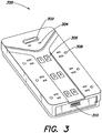
- FIG. 3 illustrates a perspective view of a power distribution device 300 according to an embodiment.
- the power distribution device 300 may be similar to the power distribution device 100, and may operate in a similar or same manner as the power distribution device 100.
- the power distribution device 300 includes a switch 302, a mode indicator 304, a plurality of LED indicators including a first LED indicator 306, a plurality of outputs including a first output 308, and a connection port 310.
- the switch 302 is configured to switch between modes of operation of the power distribution device 300.
- the switch 302 may enable the power distribution device to switch between a normal mode of operation in which power provision is disabled to a most-recently-connected output upon detection of an overload condition, and a smart mode of operation in which a priority list is provided to disable outputs in a hierarchical list when an overload condition occurs.
- the switch 302 is illustrated as a two-state rocker switch, in alternate embodiments the switch 302 may be any other type of switch, such as a hardware or software switch having any number of states.
- the mode indicator 304 may indicate a mode of operation in which the power distribution device 300 is operating.
- the mode indicator 304 may include a first LED indicator configured to be illuminated when the power distribution device 300 is in a normal mode of operation, and a second LED indicator configured to be illuminated when the power distribution device 300 is in a smart mode of operation.
- Each LED indicator of the plurality of LED indicators is configured to be associated with, and indicate the status of, an associated output of the plurality of outputs.
- the first LED indicator 306 is configured to indicate a status (for example, providing power or not providing power) of the first output 308.
- the connection port 310 is configured to enable a wired connection between the power distribution device 300 and an external entity, such as a computing device.
- the external entity may include a personal computer, laptop computer, tablet computer, smartphone, and so forth.
- the wired connection to the connection port 310 may enable a user of the external entity to provide information to the power distribution device 300.
- a user of the external entity may provide configuration information to the power distribution device 300.
- the configuration information may include, for example, a priority list indicating an order in which to disable outputs in the event of an overcurrent condition.
- a wireless connection may be used to provide configuration data to the power distribution device 300.
- the outputs 114a, 114b, 114c, and 114d are each connected to a load drawing a current of 3.5A.
- the power distribution device 100 is therefore providing a total current of 14A.
- the circuit breaker 108 is rated to withstand a current of 15A, and the MCU 122 is configured to disable a switching device corresponding to a most-recently-connected load responsive to a total current draw exceeding 15A.
- a load is subsequently connected to the output 114e, which draws a current of 16A, yielding a total output current of 30A from the power distribution device 100.
- the MCU 122 may receive electrical characteristic information from the sense circuit 112 indicating that the total current is 30A, and determine that the total current provided by the power distribution device 100 exceeds 15A. In response, the MCU 122 disables the switching device corresponding to the output 114e, thereby discontinuing current provision to the load connected to the output 114e.
- the total current output by the power distribution device 100 returns to 14A, while power provision to the outputs 114a-114d continues uninterrupted.
- the MCU 122 may be configured to address an overcurrent condition before the circuit breaker 108 is tripped.
- the total current through the circuit breaker 108 is approximately 200% the rated current of the circuit breaker 108.
- the circuit breaker 108 may be rated to trip after approximately four seconds when the total current is approximately 200% the rated current.
- the MCU 122 may be configured to disable a switching device in less than four seconds such that the overcurrent condition is eliminated or mitigated before the circuit breaker 108 is activated.
- the outputs 114a, 114b, 114c, and 114d are each connected to a load drawing a current of 3.5A.
- the power distribution device 100 is therefore providing a total current of 14A.
- the circuit breaker 108 is rated to withstand a current of 15A, and the MCU 122 is configured with a priority list of switching devices to disable responsive to detecting an overcurrent condition.
- the MCU 122 is configured to disable, in order, the switching devices corresponding to the outputs 114a, 114b, 114c, 114d, 114e, and 114f, such that the switching device 126 corresponding to the output 114a is disabled first, and the switching device corresponding to the output 114f is disabled last.
- a load drawing 5A is subsequently connected to the output 114e, yielding a total output current of 19A from the power distribution device 100.
- the MCU 122 may receive electrical characteristic information from the sense circuit 112 indicating that the total current is 19A, and determine that the total current provided by the power distribution device 100 exceeds 15A. In response, the MCU 122 disables the switching device corresponding to the first output in the priority list, specifically, the switching device 126 corresponding to the output 114a.
- the current provided by the output 114a is reduced from approximately 3.5A to approximately 0A, yielding a total output current of 15.5A.
- the MCU 122 may determine that the total current provided by the power distribution device 100 still exceeds 15A. In response, the MCU 122 disables the switching device corresponding to the second output in the priority list, specifically, the switching device corresponding to the second output 114b. The current provided by the output 114b is reduced from approximately 3.5A to approximately 0A. The total current output by the power distribution device 100 drops to approximately 12A, while power provision to the outputs 114c-114e continues uninterrupted. Similar to the first example discussed above, the MCU 122 addresses the overcurrent condition before the circuit breaker 108 is tripped.
- the outputs 114a, 114b, 114c, and 114d are each connected to a load drawing a current of 3.5A.
- the power distribution device 100 is therefore providing a total current of 14A.
- the circuit breaker 108 is rated to withstand a current of 15A, and the MCU 122 is configured to execute a dynamic determination of a switching device to disable responsive to detecting an overcurrent condition.
- the dynamic determination may be based on electrical characteristic information.
- a load drawing 16A is subsequently connected to the output 114e, yielding a total output current of 30A from the power distribution device 100.
- the MCU 122 may receive electrical characteristic information from the sense circuit 112 indicating that the total current is 30A, and determine that the total current provided by the power distribution device 100 exceeds 15A.
- the MCU 122 may determine, based on the electrical characteristic information from the sense circuit 112 relating specifically to the output 114e, that the load connected to the output 114e draws more current than the circuit breaker 108 is rated to withstand.
- the MCU 122 may therefore select the switching device corresponding to the output 114e to disable, because the load connected to the output 114e alone draws more current than the circuit breaker 108 is rated to withstand. Therefore, the MCU 122 may disable the elected switching device responsive to determining that the power distribution device 100 cannot support the connected load.
- the controller 110 may control certain aspects of the power distribution device 100. Using data stored in associated memory, the controller 110 also executes one or more instructions stored on one or more non-transitory computer-readable media that may result in manipulated data. In some examples, the controller 110 may include one or more processors or other types of controllers. In one example, the controller 110 performs a portion of the functions disclosed herein on a processor and performs another portion using an Application-Specific Integrated Circuit (ASIC) tailored to perform particular operations. As illustrated by these examples, examples in accordance with the present invention may perform the operations described herein using many specific combinations of hardware and software and the invention is not limited to any particular combination of hardware and software components.
- ASIC Application-Specific Integrated Circuit
- the MCU 122 may be powered by the LPS 116.
- the LPS 116 may receive electrical power via the line input 102, condition the electrical power, and provide the conditioned power to the MCU 122.
- Conditioning the electrical power may include rectifying AC input power to DC power, and may further include stepping down the DC power to a lower voltage level.
- Example embodiments provided herein are not intended to be limiting.
- the outputs 114a-1 14f of FIG. 1 are illustrated as being compatible with Type B plugs, in alternate embodiments, a power distribution device may have outputs configured to couple with one or more other types of plugs.
- the power distribution device 100 is illustrated as having six outputs 114a-114f, in alternate embodiments, any type of power distribution device (including power strips, outlets, uninterruptible power supplies, and power distribution units) may be configured having any number of outputs.
- the power distribution device 300 is illustrated as having six outputs, any type of power distribution device may be configured having any number of outputs.
Landscapes
- Engineering & Computer Science (AREA)
- Microelectronics & Electronic Packaging (AREA)
- Physics & Mathematics (AREA)
- Theoretical Computer Science (AREA)
- Optics & Photonics (AREA)
- General Engineering & Computer Science (AREA)
- General Physics & Mathematics (AREA)
- Power Engineering (AREA)
- Remote Monitoring And Control Of Power-Distribution Networks (AREA)
- Emergency Protection Circuit Devices (AREA)
- Supply And Distribution Of Alternating Current (AREA)
- Direct Current Feeding And Distribution (AREA)
Abstract
Description
- At least one example in accordance with the present invention relates generally to power distribution.
- Power distribution devices, including Power Distribution Units (PDUs), outlets, and power strips, are known. Power distribution devices may include an input configured to receive input power, and at least one output to provide output power. For example, a power strip may include an input plug configured to be coupled to an input power source, and several outputs respectively configured to be coupled to a corresponding load. The power strip may receive power from the input power source at the input plug, and provide output power to each of the outputs.
- According to at least one aspect of the present invention, a power distribution device is provided comprising an input configured to receive input power, a plurality of outputs, each output of the plurality of outputs being configured to provide output power, and being coupled to the input, a plurality of switching devices, each switching device of the plurality of switching devices being coupled to a respective output of the plurality of outputs, and a controller coupled to each of the plurality of switching devices, the controller being configured to receive power information indicative of the output power provided by each output of the plurality of outputs determine, based on the power information, that an overcurrent condition exists, select, based on the power information and based on the determination that the overcurrent condition exists, at least one switching device of the plurality of switching devices to disable, and disable the at least one selected switching device.
- In one embodiment, the controller is configured to select the at least one switching device of the plurality of switching devices to disable based on a change in load of an output coupled to the at least one switching device. In embodiments, the controller is configured to store a priority list of switching devices to disable, and wherein the controller is configured to select the at least one switching device to disable based on the priority list. In an embodiment, the device includes a plurality of shunt resistors, each coupled to a respective switching device of the plurality of switching devices.
- In some embodiments, the device includes a sense circuit configured to be coupled to each shunt resistor of the plurality of shunt resistors. In one embodiment, the sense circuit is configured to measure a voltage across each shunt resistor of the plurality of shunt resistors, generate, based on the measured voltage across each shunt resistor, the power information, and transmit the power information to the controller. In embodiments, the at least one switching device is a relay. In at least one embodiment, disabling the switching device includes transmitting, by the controller, one or more control signals to the relay to actuate the relay to an open and non-conducting position.
- In an embodiment, the device includes a circuit breaker coupled to the input. In embodiments, the controller is configured to disable the at least one switching device based on a current rating of the circuit breaker. In at least one embodiment, the device includes a plurality of Light-Emitting Diode (LED) indicators, each corresponding to an output of the plurality of outputs, wherein the controller is configured to illuminate at least one LED indicator of the plurality of LED indicators corresponding to the at least one switching device. In an embodiment, the method includes a piezoelectric buzzer, wherein the controller is configured to control the piezoelectric buzzer to produce a sound indicative of the at least one selected switching device being disabled.
- According to one aspect, a method of operating a power distribution device is provided, the power distribution device having an input to receive input power, and a plurality of outputs each coupled to a respective switching device of a plurality of switching devices and configured to provide output power, the method including receiving power information indicative of the output power provided by each output of the plurality of outputs, determining, based on the power information, that an overcurrent condition exists, selecting, based on the power information and based on the determination that the overcurrent condition exists, at least one switching device of the plurality of switching devices to disable, and disabling the at least one selected switching device.
- In one embodiment, selecting at least one switching device of the plurality of switching devices to disable includes selecting at least one switching device based on a change in load of an output coupled to the at least one switching device. In an embodiment, the method includes storing a priority list of switching devices to disable, and wherein selecting at least one switching device to disable includes selecting at least one lowest-priority switching device to disable from the priority list. In at least one embodiment, selecting at least one switching device of the plurality of switching devices to disable includes generating, based on the power information, a priority list of switching devices to disable, and selecting at least one lowest-priority switching device to disable from the priority list.
- In at least one embodiment, generating the priority list of switching devices to disable includes determining, based on the power information, that at least one output of the plurality of outputs is drawing more current than the power distribution device is rated to provide, and assigning, responsive to determining that the at least one output is drawing more current than the power distribution device is rated to provide, a lowest priority to at least one switching device corresponding to the at least one output. In an embodiment, at least one output is coupled to a load, and generating the priority list of switching devices to disable includes determining, based on the power information, a criticality of a mode of operation of each load corresponding to a respective output of the at least one output, and assigning a lowest priority to a switching device corresponding to an output coupled to a load in a lowest-criticality mode of operation.
- According to one aspect, a power distribution system is provided. The power distribution system includes an input configured to receive input power, a plurality of outputs, each output being configured to provide output power, and means for selecting, based on the output power, at least one output of the plurality of outputs to disable, and means for disabling the selected at least one output from providing the output power. In one embodiment, the system includes a sense circuit configured to determine power characteristic information indicative of the output power.
- Various aspects of at least one embodiment are discussed below with reference to the accompanying figures, which are not intended to be drawn to scale. The figures are included to provide an illustration and a further understanding of the various aspects and embodiments, and are incorporated in and constitute a part of this specification, but are not intended as a definition of the limits of any particular embodiment. The drawings, together with the remainder of the specification, serve to explain principles and operations of the described and claimed aspects and embodiments. In the figures, each identical or nearly identical component that is illustrated in various figures is represented by a like numeral. For purposes of clarity, not every component may be labeled in every figure. In the figures:
-
FIG. 1 illustrates a schematic diagram of a power distribution device according to an embodiment; -
FIG. 2 illustrates a process of controlling one or more switching devices according to an embodiment; and -
FIG. 3 illustrates a perspective view of a power distribution device according to an embodiment. - Examples of the methods and systems discussed herein are not limited in application to the details of construction and the arrangement of components set forth in the following description or illustrated in the accompanying drawings. The methods and systems are capable of implementation in other embodiments and of being practiced or of being carried out in various ways. Examples of specific implementations are provided herein for illustrative purposes only and are not intended to be limiting. In particular, acts, components, elements and features discussed in connection with any one or more examples are not intended to be excluded from a similar role in any other examples.
- Also, the phraseology and terminology used herein is for the purpose of description and should not be regarded as limiting. Any references to examples, embodiments, components, elements or acts of the systems and methods herein referred to in the singular may also embrace embodiments including a plurality, and any references in plural to any embodiment, component, element or act herein may also embrace embodiments including only a singularity. References in the singular or plural form are no intended to limit the presently disclosed systems or methods, their components, acts, or elements. The use herein of "including," "comprising," "having," "containing," "involving," and variations thereof is meant to encompass the items listed thereafter and equivalents thereof as well as additional items.
- References to "or" may be construed as inclusive so that any terms described using "or" may indicate any of a single, more than one, and all of the described terms. In addition, in the event of inconsistent usages of terms between this document and documents incorporated herein by reference, the term usage in the incorporated features is supplementary to that of this document; for irreconcilable differences, the term usage in this document controls.
- As discussed above, power distribution devices are generally known. Power distribution devices may have applications in many environments, including residential and commercial environments. For example, power outlets including one or more outputs are commonplace in most residential and commercial structures. Power strips including one or more receptacles may be used in residential environments and office environments. PDUs including one or more receptacles are often implemented in data centers to distribute power to one or more racks, and to distribute power to components within a rack.
- Power distribution devices may be subject to significant variations in output power demands depending on a number of connected loads and the connected loads' respective power demands. For example, consider a power strip having six outputs. At a first time, only one output of the six outputs may be connected to a load which draws a moderate current (for example, 2 Amperes [A]). At a second time, each of the six outputs may be connected to a respective load, each drawing a large amount of current (for example, 4A each). In the foregoing example, the current demand at the second time is twelve times larger than the current demand at the first time. Accordingly, the power strip is subject to significant variations in a range of possible output current demand. Particularly high current draw within the range of possible output current demand may be considered an excessive current draw.
- Excessive current draw during an overcurrent condition may cause an undesirable rise in temperature in the power strip. To mitigate or otherwise address the effects of overcurrent conditions, conventional power strips may include a circuit breaker coupled to the input and rated to withstand a specific amount of current. If the current through the circuit breaker exceeds the current rating of the circuit breaker, the circuit breaker will "trip," or open, thereby preventing current from passing through the circuit breaker and eliminating or mitigating the overcurrent condition. However, by eliminating input current to the power strip, power is no longer provided to any of the outputs.
- In one embodiment of the present disclosure, power distribution devices configured to eliminate or mitigate an overcurrent condition are provided. For example, power distribution devices are provided which are configured to eliminate or mitigate an overcurrent condition without discontinuing power provision to all receptacles of the power distribution device. Responsive to detecting an overcurrent condition, some embodiments of the present disclosure are configured to disable power provision to a subset of the receptacles to address the overcurrent condition while enabling power provision to a complementary subset of the receptacles.
- As used herein, excessive current in a power distribution device may be defined as a current in excess of a maximum permissible current value. In some embodiments, the maximum permissible current value may be a set value specified by a designer of the power distribution device. For example, the maximum permissible current value may be equal to or slightly less than a current rating of a circuit breaker. In alternate embodiments, the maximum permissible current value may be dynamically determined based on one or more parameters (for example, an ambient temperature parameter or a parameter indicative of the age of the power distribution device). In still other embodiments, the maximum permissible current value may be statically or dynamically determined according to alternate methods.
-
FIG. 1 illustrates a schematic diagram of apower distribution device 100 according to an embodiment. Thepower distribution device 100 includes aline input 102, aneutral input 104, aground connection 106, acircuit breaker 108, acontroller 110, asense circuit 112, and a plurality ofoutputs 114a-114f. Thecontroller 110 includes a Logic Power Supply (LPS) 116, a Light-Emitting Diode (LED)indicator 118, aswitch 119, anaudio output device 120, amode indicator 121, and a Micro-Controller Unit (MCU) 122. - The
output 114a includes ashunt resistor 124, aswitching device 126, and anoutput connector 128. Theoutput connector 128 includes aline output 130, aneutral input 132, and aground connection 134. Theoutputs 114b-114f may be substantially similar to theoutput 114a in at least one embodiment. Accordingly, while the operation and configuration of theoutput 114a is specifically discussed in the following examples for purposes of explanation only, theoutputs 114b-114f are operated and configured similarly. - The
line input 102 is configured to receive input power (for example, input AC mains power) from an input power source (not illustrated), and is configured to be coupled to thecircuit breaker 108. Theneutral input 104 is configured to be coupled to the input power source, and is configured to be coupled to theLPS 116 and theneutral input 132. Theground connection 106 is configured to be coupled to a reference node operating at a reference voltage (for example, a ground voltage), and is configured to be coupled to theground connection 134. - The
circuit breaker 108 is configured to be coupled to theline input 102 at a first connection, and is configured to be coupled to theLPS 116 and theshunt resistor 124 at a second connection. Thesense circuit 112 is configured to be coupled to theMCU 122, and is configured to be coupled across theshunt resistor 124. TheLPS 116 is configured to be coupled to a bus connecting thecircuit breaker 108 and theshunt resistor 124 at a first input, is configured to be coupled to a bus connecting theneutral input 104 and theneutral input 132 at a second input, and is configured to be coupled to theMCU 122 at an output. - The
LED indicator 118 is configured to be coupled to theMCU 122. Theswitch 119 is configured to be coupled to theMCU 122. Theaudio output device 120 is configured to be coupled to theMCU 122. Themode indicator 121 is configured to be coupled to theMCU 122. TheMCU 122 is configured to be coupled to thesense circuit 112, theLPS 116, theLED indicator 118, theswitch 119, theaudio output device 120, themode indicator 121, and theswitching device 126. Theshunt resistor 124 is configured to be coupled to thecircuit breaker 108, thesense circuit 112, and theLPS 116 at a first connection, and is configured to be coupled to thesense circuit 112 and theswitching device 126 at a second connection. Theswitching device 126 is configured to be coupled to theshunt resistor 124, and is configured to be selectively (i.e., switchably) coupled to theline output 130. In one embodiment, theswitching device 126 is a relay configured to be communicatively coupled to, and controlled by, theMCU 122. - The
output connector 128 may be configured to be coupled to a plug configured to receive power to be provided to a load coupled to the plug. For example, theoutput connector 128 may be configured to be coupled to a plug having three pins (not illustrated). Theline output 130 is configured to be coupled to theswitching device 126, and may be configured to be coupled to a first pin of the three pins of the plug. Theneutral input 132 is configured to be coupled to theneutral input 104, and may be configured to be coupled to a second pin of the three pins of the plug. Theground connection 134 is configured to be coupled to theground connection 106, and may be configured to be coupled to a third pin of the three pins of the plug. - In one embodiment, the
power distribution device 100 is generally configured to receive line power at theline input 102 from a power source and provide at least a portion of the line power to one or more of theoutputs 114a-114f. In one example, power may be provided only to loads connected to outputs having a corresponding switching device in a closed (i.e., conducting) position. TheMCU 122 may communicate one or more control signals to the switching devices to control a position of the switching devices. - For example, if the
output 114a is coupled to a load via theoutput connector 128, power from theline input 102 will only be provided to the load if theswitching device 126 is in a closed and conducting position. In some embodiments, a position of theswitching device 126 is controlled by theMCU 122. Accordingly, theMCU 122 may selectively provide power to a subset of theoutputs 114a-114f by selectively closing the switching devices corresponding to output connectors for which power is to be provided, and opening the switching devices corresponding to output connectors for which power is to not be provided. In some embodiments, "disabling a switching device" may include controlling the switching device to be in an open and non-conducting position. - A state of the switching devices corresponding to the
outputs 114a-114f may be controlled by theMCU 122 in connection with information received from thesense circuit 112.FIG. 2 illustrates aprocess 200 for controlling a corresponding state of one or more switching devices. For example, theprocess 200 may be executed by theMCU 122. Theprocess 200 includes acts of receiving power information, determining if a criterion is satisfied, selecting at least one switching device to disable, disabling the at least one switching device, and providing a notification of the disabling. - At
act 202, theprocess 200 begins. Atact 204, power information is received. For example, theMCU 122 may receive the power information from thesense circuit 112. Thesense circuit 112 may determine the power information by measuring a voltage drop across the shunt resistors, including theshunt resistor 124, respectively coupled to each of theoutputs 114a-114f. The power information may be information indicative of a total amount of power provided to theoutputs 114a-114f, or may be information indicative of power provided to each of theoutputs 114a-114f individually. The power information may be expressed in terms of power consumed, or may be expressed in terms of current, voltage, or a combination thereof. For example, thesense circuit 112 may measure a voltage across each shunt resistor of theoutputs 114a-114f, and determine a corresponding current through each shunt resistor using the measured voltage where the value of the shunt resistor is known. - At
act 206, a determination is made as to whether a criterion is satisfied. Generally speaking, satisfaction of the criterion may indicate that an overcurrent condition may be present. For example, determining whether the criterion is satisfied may include determining whether a total output current (i.e., the cumulative current provided by theoutputs 114a-114f), which is substantially equivalent to the input current, exceeds a threshold value. - As discussed above, the threshold value may be a static value (for example, set by a designer of the
power distribution device 100 based on a rating of the circuit breaker 108), or may be a dynamic value. For example, theMCU 122 may dynamically determine a threshold current value based on a temperature of or around thepower distribution device 100, or based on a date of manufacture of thepower distribution device 100. If the criterion is not satisfied (206 NO), which may indicate that a level of a current output by thepower distribution device 100 is within a permissible range, then theprocess 200 returns to act 204. - Otherwise, if the criterion is satisfied (206 YES), then the
process 200 continues to act 208. For example, determining that the criterion is satisfied may include determining that a total current through thepower distribution device 100 is excessively high. Atact 208, one or more switching devices are selected to be disabled to reduce a total output current. A process of selecting one or more switching devices to be disabled is discussed in greater detail below. - At
act 210, one or more switching devices are disabled. For example, disabling one or more switching devices may include controlling, by theMCU 122, the one or more switching devices selected atact 208 to be in an open and non-conducting state, thereby substantially eliminating current passing through the selected switching device. Atact 212, a notification indicative of the overcurrent condition is provided. For example, thepower distribution device 100 may provide a notification to one or more users indicating that power provision to one or more of theoutputs 114a-114f has been disabled. In one embodiment, theMCU 122 is configured to provide one or more signals to one or both of theLED indicator 118 and theaudio output device 120, as discussed in greater detail below. Atact 214, theprocess 200 ends. - Execution of the
process 200 may enable a power distribution device having several outputs to continue providing power to at least a subset of the several outputs responsive to detecting an overcurrent condition. In one embodiment, one or more of the several outputs is selected and disabled from providing power to reduce the total output current to a permissible current level. For example, a permissible current level may be a current level at or below the maximum current rating of a circuit breaker, such as thecircuit breaker 108. Accordingly, an overcurrent condition may be addressed without tripping thecircuit breaker 108, and without disabling power provision to all of theoutputs 114a-114f. - Selecting one or more switching devices to be disabled, as discussed above in connection with
act 208 of theprocess 200, may be implemented according to one of several embodiments. In one embodiment, a switching device corresponding to a most-recently-connected load is selected. For example, if an overcurrent condition is detected responsive to a load being connected to theoutput 114a, then theswitching device 126 may be selected to be disabled because it corresponds to a most-recently-connected load. Alternatively, a most-recently-connected load may more broadly include a load which most recently changed a power draw which caused an overcurrent condition. For example, if a load which was not most recently connected changes a mode of operation and suddenly draws more power, the load may be considered a most-recently-connected load regardless of whether the load was most recently physically connected to thepower distribution device 100. - In another embodiment, a priority list of switching devices may be determined, and a lowest-priority switching device may be selected to be disabled. For example, a user may establish a static priority list indicating that the
output 114a is a lowest-priority receptacle, theoutput 114b is a second-lowest-priority receptacle, and so forth. The priority list may be stored within theMCU 122 or in external memory or logic circuits coupled to theMCU 122. If an overcurrent condition is detected, regardless of which of theoutputs 114a-114f was most recently connected to a load, theswitching device 126 corresponding to theoutput 114a may be disabled first because theoutput 114a is the lowest-priority output. If the overcurrent condition persists, then the switching device corresponding to theoutput 114b may be disabled because it is a next-lowest-priority output, and so forth until the overcurrent condition is eliminated or reduced to a desired level. - In another embodiment, a dynamic determination may be made based on one or more electrical characteristics to select a switching device corresponding to one of the
outlet receptacles 114a-114f to disable. The electrical characteristics may be received from thesense circuit 112 and may be indicative of current, voltage, or power provided to each respective load. For example, the dynamic determination may include determining, by theMCU 122, that a single load is drawing more current than thecircuit breaker 108 is rated to withstand. Accordingly, theMCU 122 may determine that a switching device corresponding to the single load should be disabled because, even if the single load were operating in isolation, thecircuit breaker 108 would be tripped. - In some embodiments, the
MCU 122 may perform a dynamic determination based on a determined criticality of a mode of operation of a load corresponding to a respective switching device. Criticality of a load generally refers to a level of importance that a load receives power, where a high criticality load corresponds to a load for which power provision is very important, and a low criticality load corresponds to a load for which power provision is less important. For example, methods and systems for determining characteristics a mode of operation of a load connected to a power distribution device are discussed inU.S. Patent No. 9,047,071 - In some embodiments, the
power distribution device 100 may be configured to select a switching device to disable according to two or more of the foregoing implementations. For example, theswitch 119 may be configured to switch between a first switching device selection implementation (for example, by disabling a most-recently-connected switching device) and a second switching device selection implementation (for example, by disabling a switching device according to a dynamic determination). In alternate embodiments, theswitch 119 may be configured to switch between any number of states. Theswitch 119 may be a hardware switch, a software switch, or a combination of both. - The
mode indicator 121 may indicate a mode of operation which has been switched to. For example, themode indicator 121 may include one or more LED indicators, whereby a first LED indicator may be illuminated to indicate that thepower distribution device 100 is operating in a first mode of operation, and a second LED indicator may be illuminated to indicate that thepower distribution device 100 is operating in a second mode of operation. - As discussed above with respect to act 212 of the
process 200, providing a notification to users of thepower distribution device 100 may be executed in connection with one or more LED indicators and one or more audio output devices, such as theLED indicator 118 andaudio output device 120. Although asingle LED indicator 118 and asingle audio device 120 are illustrated, in alternate embodiments, theLED indicator 118 may include multiple LED indicators, and theaudio output device 120 may include multiple audio output devices. For example, in some embodiments, each of theoutputs 114a-114f may correspond to a respective LED indicator, such that a disabled output may be indicated by a corresponding LED indicator being illuminated. A disabled output may be indicated by a corresponding LED indicator being illuminated in a first color (for example, red), and an enabled output may be indicated by a corresponding LED indicator being illuminated in a second color (for example, green). - In an embodiment having a single LED indicator, the single LED indicator may be illuminated to indicate that at least one of the
outputs 114a-114f has been disabled. In yet another embodiment, the single LED indicator may be selectively illuminated and de-illuminated, whereby a blinking pattern of the single LED may be indicative of which of theoutputs 114a-114f are enabled, and which are disabled. - Providing the one or more signals to the
audio output device 120 may include providing the one or more signals to a piezoelectric buzzer, a speaker, or both. For example, where theaudio output device 120 includes a piezoelectric buzzer, providing the one or more signals to theaudio output device 120 may include controlling the piezoelectric buzzer to output a buzzing sound indicative of power provision by one of theoutputs 114a-114f being disabled. In another embodiment, where theaudio output device 120 includes a speaker, providing the one or more signals to theaudio output device 120 may include controlling the speaker to output a message describing the condition of theoutputs 114a-114f. For example, the message may be a human- or machine-comprehensible message stating that power provision to theoutput 114a and theoutput 114c has been disabled. -
FIG. 3 illustrates a perspective view of apower distribution device 300 according to an embodiment. For example, thepower distribution device 300 may be similar to thepower distribution device 100, and may operate in a similar or same manner as thepower distribution device 100. Thepower distribution device 300 includes aswitch 302, amode indicator 304, a plurality of LED indicators including afirst LED indicator 306, a plurality of outputs including afirst output 308, and aconnection port 310. - The
switch 302 is configured to switch between modes of operation of thepower distribution device 300. For example, theswitch 302 may enable the power distribution device to switch between a normal mode of operation in which power provision is disabled to a most-recently-connected output upon detection of an overload condition, and a smart mode of operation in which a priority list is provided to disable outputs in a hierarchical list when an overload condition occurs. Although theswitch 302 is illustrated as a two-state rocker switch, in alternate embodiments theswitch 302 may be any other type of switch, such as a hardware or software switch having any number of states. - The
mode indicator 304 may indicate a mode of operation in which thepower distribution device 300 is operating. For example, themode indicator 304 may include a first LED indicator configured to be illuminated when thepower distribution device 300 is in a normal mode of operation, and a second LED indicator configured to be illuminated when thepower distribution device 300 is in a smart mode of operation. Each LED indicator of the plurality of LED indicators is configured to be associated with, and indicate the status of, an associated output of the plurality of outputs. For example, thefirst LED indicator 306 is configured to indicate a status (for example, providing power or not providing power) of thefirst output 308. - The
connection port 310 is configured to enable a wired connection between thepower distribution device 300 and an external entity, such as a computing device. For example, the external entity may include a personal computer, laptop computer, tablet computer, smartphone, and so forth. The wired connection to theconnection port 310 may enable a user of the external entity to provide information to thepower distribution device 300. For example, a user of the external entity may provide configuration information to thepower distribution device 300. The configuration information may include, for example, a priority list indicating an order in which to disable outputs in the event of an overcurrent condition. In other embodiments, a wireless connection may be used to provide configuration data to thepower distribution device 300. - Example embodiments of the present disclosure will now be described. In a first example, the
outputs power distribution device 100 is therefore providing a total current of 14A. Thecircuit breaker 108 is rated to withstand a current of 15A, and theMCU 122 is configured to disable a switching device corresponding to a most-recently-connected load responsive to a total current draw exceeding 15A. - A load is subsequently connected to the
output 114e, which draws a current of 16A, yielding a total output current of 30A from thepower distribution device 100. TheMCU 122 may receive electrical characteristic information from thesense circuit 112 indicating that the total current is 30A, and determine that the total current provided by thepower distribution device 100 exceeds 15A. In response, theMCU 122 disables the switching device corresponding to theoutput 114e, thereby discontinuing current provision to the load connected to theoutput 114e. The total current output by thepower distribution device 100 returns to 14A, while power provision to theoutputs 114a-114d continues uninterrupted. - The
MCU 122 may be configured to address an overcurrent condition before thecircuit breaker 108 is tripped. For example, in the foregoing example, the total current through thecircuit breaker 108 is approximately 200% the rated current of thecircuit breaker 108. Thecircuit breaker 108 may be rated to trip after approximately four seconds when the total current is approximately 200% the rated current. Accordingly, theMCU 122 may be configured to disable a switching device in less than four seconds such that the overcurrent condition is eliminated or mitigated before thecircuit breaker 108 is activated. - In a second example, the
outputs power distribution device 100 is therefore providing a total current of 14A. Thecircuit breaker 108 is rated to withstand a current of 15A, and theMCU 122 is configured with a priority list of switching devices to disable responsive to detecting an overcurrent condition. More specifically, in the illustrated example, theMCU 122 is configured to disable, in order, the switching devices corresponding to theoutputs switching device 126 corresponding to theoutput 114a is disabled first, and the switching device corresponding to theoutput 114f is disabled last. - A load drawing 5A is subsequently connected to the
output 114e, yielding a total output current of 19A from thepower distribution device 100. TheMCU 122 may receive electrical characteristic information from thesense circuit 112 indicating that the total current is 19A, and determine that the total current provided by thepower distribution device 100 exceeds 15A. In response, theMCU 122 disables the switching device corresponding to the first output in the priority list, specifically, theswitching device 126 corresponding to theoutput 114a. The current provided by theoutput 114a is reduced from approximately 3.5A to approximately 0A, yielding a total output current of 15.5A. - The
MCU 122 may determine that the total current provided by thepower distribution device 100 still exceeds 15A. In response, theMCU 122 disables the switching device corresponding to the second output in the priority list, specifically, the switching device corresponding to thesecond output 114b. The current provided by theoutput 114b is reduced from approximately 3.5A to approximately 0A. The total current output by thepower distribution device 100 drops to approximately 12A, while power provision to theoutputs 114c-114e continues uninterrupted. Similar to the first example discussed above, theMCU 122 addresses the overcurrent condition before thecircuit breaker 108 is tripped. - In a third example, the
outputs power distribution device 100 is therefore providing a total current of 14A. Thecircuit breaker 108 is rated to withstand a current of 15A, and theMCU 122 is configured to execute a dynamic determination of a switching device to disable responsive to detecting an overcurrent condition. For example, the dynamic determination may be based on electrical characteristic information. - A load drawing 16A is subsequently connected to the
output 114e, yielding a total output current of 30A from thepower distribution device 100. TheMCU 122 may receive electrical characteristic information from thesense circuit 112 indicating that the total current is 30A, and determine that the total current provided by thepower distribution device 100 exceeds 15A. TheMCU 122 may determine, based on the electrical characteristic information from thesense circuit 112 relating specifically to theoutput 114e, that the load connected to theoutput 114e draws more current than thecircuit breaker 108 is rated to withstand. TheMCU 122 may therefore select the switching device corresponding to theoutput 114e to disable, because the load connected to theoutput 114e alone draws more current than thecircuit breaker 108 is rated to withstand. Therefore, theMCU 122 may disable the elected switching device responsive to determining that thepower distribution device 100 cannot support the connected load. - As discussed above, the
controller 110 may control certain aspects of thepower distribution device 100. Using data stored in associated memory, thecontroller 110 also executes one or more instructions stored on one or more non-transitory computer-readable media that may result in manipulated data. In some examples, thecontroller 110 may include one or more processors or other types of controllers. In one example, thecontroller 110 performs a portion of the functions disclosed herein on a processor and performs another portion using an Application-Specific Integrated Circuit (ASIC) tailored to perform particular operations. As illustrated by these examples, examples in accordance with the present invention may perform the operations described herein using many specific combinations of hardware and software and the invention is not limited to any particular combination of hardware and software components. - In at least one embodiment, the
MCU 122 may be powered by theLPS 116. For example, theLPS 116 may receive electrical power via theline input 102, condition the electrical power, and provide the conditioned power to theMCU 122. Conditioning the electrical power may include rectifying AC input power to DC power, and may further include stepping down the DC power to a lower voltage level. - Example embodiments provided herein are not intended to be limiting. For example, although the
outputs 114a-1 14f ofFIG. 1 are illustrated as being compatible with Type B plugs, in alternate embodiments, a power distribution device may have outputs configured to couple with one or more other types of plugs. Furthermore, although thepower distribution device 100 is illustrated as having sixoutputs 114a-114f, in alternate embodiments, any type of power distribution device (including power strips, outlets, uninterruptible power supplies, and power distribution units) may be configured having any number of outputs. Similarly, although thepower distribution device 300 is illustrated as having six outputs, any type of power distribution device may be configured having any number of outputs. - Having thus described several aspects of at least one embodiment, it is to be appreciated various alterations, modifications, and improvements will readily occur to those skilled in the art. Such alterations, modifications, and improvements are intended to be part of this disclosure, and are intended to be within the scope of the disclosure. Accordingly, the foregoing description and drawings are by way of example only.
Claims (15)
- A power distribution device comprising:an input configured to receive input power;a plurality of outputs, each output of the plurality of outputs being configured to provide output power, and being coupled to the input;a plurality of switching devices, each switching device of the plurality of switching devices being coupled to a respective output of the plurality of outputs; anda controller coupled to each switching device of the plurality of switching devices, the controller being configured to:receive power information indicative of the output power provided by each output of the plurality of outputs;determine, based on the power information, that an overcurrent condition exists;select, based on the power information and based on the determination that the overcurrent condition exists, at least one switching device of the plurality of switching devices to disable; anddisable the at least one selected switching device.
- The power distribution device of claim 1, wherein the controller is configured to select the at least one switching device of the plurality of switching devices to disable based on a change in load of an output coupled to the at least one switching device.
- The power distribution device of claim 1, wherein the controller is configured to store a priority list of switching devices to disable, and wherein the controller is configured to select the at least one switching device to disable based on the priority list.
- The power distribution device of claim 1, further comprising:a plurality of shunt resistors, each coupled to a respective switching device of the plurality of switching devices, anda sense circuit configured to be coupled to each shunt resistor of the plurality of shunt resistors.
- The power distribution device of claim 4, wherein the sense circuit is configured to:measure a voltage across each shunt resistor of the plurality of shunt resistors;generate, based on the measured voltage across each shunt resistor, the power information; andtransmit the power information to the controller.
- The power distribution device of claim 1, wherein the at least one switching device is a relay, and wherein disabling the at least one switching device includes transmitting, by the controller, one or more control signals to the relay to actuate the relay to an open and non-conducting position.
- The power distribution device of claim 1, further comprising a circuit breaker coupled to the input, and wherein the controller is configured to disable the at least one switching device based on a current rating of the circuit breaker.
- The power distribution device of claim 1, further comprising a plurality of Light-Emitting Diode (LED) indicators, each corresponding to an output of the plurality of outputs, wherein the controller is configured to illuminate at least one LED indicator of the plurality of LED indicators corresponding to the at least one switching device.
- The power distribution device of claim 1, further comprising a piezoelectric buzzer, wherein the controller is configured to control the piezoelectric buzzer to produce a sound indicative of the at least one selected switching device being disabled.
- A method of operating a power distribution device having an input to receive input power, and a plurality of outputs each coupled to a respective switching device of a plurality of switching devices and configured to provide output power, the method including:receiving power information indicative of the output power provided by each output of the plurality of outputs;determining, based on the power information, that an overcurrent condition exists;selecting, based on the power information and based on the determination that the overcurrent condition exists, at least one switching device of the plurality of switching devices to disable; anddisabling the at least one selected switching device.
- The method of claim 10, wherein selecting at least one switching device of the plurality of switching devices to disable includes selecting at least one switching device based on a change in load of an output coupled to the at least one switching device.
- The method of claim 10, further comprising storing a priority list of switching devices to disable, and wherein selecting at least one switching device to disable includes selecting at least one lowest-priority switching device to disable from the priority list.
- The method of claim 10, wherein selecting at least one switching device of the plurality of switching devices to disable includes:generating, based on the power information, a priority list of switching devices to disable; andselecting at least one lowest-priority switching device to disable from the priority list.
- The method of claim 13, wherein generating the priority list of switching devices to disable includes:determining, based on the power information, that at least one output of the plurality of outputs is drawing more current than the power distribution device is rated to provide; andassigning, responsive to determining that the at least one output is drawing more current than the power distribution device is rated to provide, a lowest priority to at least one switching device corresponding to the at least one output.
- The method of claim 13, wherein at least one output is coupled to a load, and wherein generating the priority list of switching devices to disable includes:determining, based on the power information, a criticality of a mode of operation of each load corresponding to a respective output of the at least one output; andassigning a lowest priority to a switching device corresponding to an output coupled to a load in a lowest-criticality mode of operation.
Applications Claiming Priority (1)
| Application Number | Priority Date | Filing Date | Title |
|---|---|---|---|
| US16/144,189 US11870186B2 (en) | 2018-09-27 | 2018-09-27 | Surge protector with active overload protection |
Publications (2)
| Publication Number | Publication Date |
|---|---|
| EP3641086A2 true EP3641086A2 (en) | 2020-04-22 |
| EP3641086A3 EP3641086A3 (en) | 2020-07-29 |
Family
ID=68072128
Family Applications (1)
| Application Number | Title | Priority Date | Filing Date |
|---|---|---|---|
| EP19199840.0A Withdrawn EP3641086A3 (en) | 2018-09-27 | 2019-09-26 | Surge protector with active overload protection |
Country Status (3)
| Country | Link |
|---|---|
| US (1) | US11870186B2 (en) |
| EP (1) | EP3641086A3 (en) |
| CN (1) | CN110957699B (en) |
Families Citing this family (6)
| Publication number | Priority date | Publication date | Assignee | Title |
|---|---|---|---|---|
| US11581728B1 (en) * | 2019-02-12 | 2023-02-14 | Equinix, Inc. | Soft breaker circuit |
| US12019490B2 (en) * | 2020-12-28 | 2024-06-25 | Robert Bosch Gmbh | System and method to detect malicious can controller behavior from adversarial clock control |
| CN113036712B (en) * | 2021-05-28 | 2021-08-17 | 四块科技(深圳)有限公司 | Smart power-off method, device, smart socket and storage medium of smart socket |
| CN114678841A (en) * | 2022-03-25 | 2022-06-28 | 深圳市道通合创新能源有限公司 | Control method of terminal equipment, storage medium, total meter device and electricity meter system |
| US11831143B1 (en) * | 2023-01-17 | 2023-11-28 | Legrand DPC, LLC | Circuit breaker forensics for power distribution units |
| EP4554024A1 (en) * | 2023-11-13 | 2025-05-14 | Future Systems Besitz GmbH | Load-break switching device, switching cabinet, automation system and method for operating a load-break switching device |
Citations (5)
| Publication number | Priority date | Publication date | Assignee | Title |
|---|---|---|---|---|
| US20040148060A1 (en) * | 2003-01-24 | 2004-07-29 | Rong-Jung Lee | Method and device for power management and control of power supply system |
| US20080309164A1 (en) * | 2005-11-30 | 2008-12-18 | Seong-Kyu Lim | Power-Controllable Outlet Receptacle |
| US9047071B2 (en) | 2010-05-21 | 2015-06-02 | Schneider Electric It Corporation | Method and apparatus for controlling distribution of power |
| US20160013646A1 (en) * | 2014-07-14 | 2016-01-14 | Heart Transverter, S.A. | Load management, metering, and demand response module |
| US20170279273A1 (en) * | 2014-09-18 | 2017-09-28 | Ergotron, Inc. | Electrical load management system and method |
Family Cites Families (16)
| Publication number | Priority date | Publication date | Assignee | Title |
|---|---|---|---|---|
| US5844326A (en) * | 1997-06-23 | 1998-12-01 | Cruising Equipment Company, Inc. | Managed electrical outlet for providing rank-ordered over-current protection |
| US6232754B1 (en) | 1999-08-15 | 2001-05-15 | Philips Electronics North America Corporation | Sleep-mode-ready switching power converter |
| US7630186B2 (en) | 2002-05-06 | 2009-12-08 | Cyber Switching, Inc. | Current protection apparatus and method |
| CN2821983Y (en) | 2005-07-04 | 2006-09-27 | 至宝电脑兴业股份有限公司 | Current-limiting protection circuit for power supplies |
| US7519438B2 (en) | 2005-11-09 | 2009-04-14 | Abb Technology Ag | Method and a tool for calculating and displaying fault response tolerances for a power switching device |
| US9658665B2 (en) * | 2009-09-29 | 2017-05-23 | Zonit Structured Solutions, Llc | Parallel redundant power distribution |
| KR101066736B1 (en) | 2007-06-12 | 2011-09-21 | 엘지전자 주식회사 | Portable device |
| US7903382B2 (en) * | 2007-06-19 | 2011-03-08 | General Electric Company | MEMS micro-switch array based on current limiting enabled circuit interrupting apparatus |
| US7554409B1 (en) * | 2007-09-27 | 2009-06-30 | Cirrus Logic, Inc. | Over-current protection circuit and method for protecting switching power amplifier circuits |
| US7795759B2 (en) * | 2008-06-27 | 2010-09-14 | iGo, Inc | Load condition controlled power strip |
| US9401635B2 (en) * | 2009-04-27 | 2016-07-26 | Hewlett Packard Enterprise Development Lp | Switching power supply for a load in stanby mode |
| EP3161927B1 (en) | 2014-06-30 | 2019-08-14 | Schneider Electric IT Corporation | Load balancing for power distribution |
| US9263877B1 (en) | 2014-12-30 | 2016-02-16 | Api Technologies Corp. | Temperature-compensated current monitoring |
| EP3160033B1 (en) | 2015-10-20 | 2022-12-14 | Schneider Electric IT Corporation | Current sensing system for full-bridge pulse-width modulated inverter system |
| US10601187B2 (en) * | 2017-06-20 | 2020-03-24 | International Business Machines Corporation | Overload prevention in a power distribution unit with electrical power outlet sockets |
| TWI652580B (en) * | 2018-04-13 | 2019-03-01 | 緯創資通股份有限公司 | Line collecting device and power supply method thereof |
-
2018
- 2018-09-27 US US16/144,189 patent/US11870186B2/en active Active
-
2019
- 2019-09-26 EP EP19199840.0A patent/EP3641086A3/en not_active Withdrawn
- 2019-09-26 CN CN201910915556.6A patent/CN110957699B/en active Active
Patent Citations (5)
| Publication number | Priority date | Publication date | Assignee | Title |
|---|---|---|---|---|
| US20040148060A1 (en) * | 2003-01-24 | 2004-07-29 | Rong-Jung Lee | Method and device for power management and control of power supply system |
| US20080309164A1 (en) * | 2005-11-30 | 2008-12-18 | Seong-Kyu Lim | Power-Controllable Outlet Receptacle |
| US9047071B2 (en) | 2010-05-21 | 2015-06-02 | Schneider Electric It Corporation | Method and apparatus for controlling distribution of power |
| US20160013646A1 (en) * | 2014-07-14 | 2016-01-14 | Heart Transverter, S.A. | Load management, metering, and demand response module |
| US20170279273A1 (en) * | 2014-09-18 | 2017-09-28 | Ergotron, Inc. | Electrical load management system and method |
Also Published As
| Publication number | Publication date |
|---|---|
| CN110957699A (en) | 2020-04-03 |
| US20200106221A1 (en) | 2020-04-02 |
| US11870186B2 (en) | 2024-01-09 |
| EP3641086A3 (en) | 2020-07-29 |
| CN110957699B (en) | 2024-08-02 |
Similar Documents
| Publication | Publication Date | Title |
|---|---|---|
| US11870186B2 (en) | Surge protector with active overload protection | |
| KR101738618B1 (en) | Multiconcent and control method thereof | |
| AU2011326721A1 (en) | Static bypass switch with built in transfer switch capabilities | |
| EP3157123B1 (en) | Mitigating an effect of a downstream failure in an automatic transfer switching system | |
| CN108110728A (en) | Protection switch | |
| US20250357741A1 (en) | System and method for discerning arcing in electrical wiring | |
| US11563433B2 (en) | Direct current circuit switch | |
| US11152778B2 (en) | Low-voltage circuit breaker and method | |
| CN113098024A (en) | Capacitor system, method of operating a system and power factor correction circuit | |
| CN117916977A (en) | Boot setup for companion module graphic display | |
| US20180294641A1 (en) | Dc-dc converters having bullet terminals | |
| KR20200061200A (en) | Operation apparatus for substation and the control method thereof | |
| EP4030585A1 (en) | Intelligent load control to support peak load demands in electrical circuits | |
| KR101592464B1 (en) | Socket for protecting standby power and control methdo using the same | |
| US11955833B2 (en) | Intelligent load control to support peak load demands in electrical circuits | |
| US11038351B2 (en) | System and method for power sharing between a plurality of electrical appliances on an alternating current circuit | |
| JP6714141B2 (en) | Electronic circuit breaker | |
| US20190273394A1 (en) | Power supply with programmable restriction | |
| US20200176968A1 (en) | Power distribution unit with aggregate current control | |
| KR101273708B1 (en) | Intelligent outlet for power saving and driving method thereof | |
| KR20140126934A (en) | Intelligent outlet for power saving and driving method thereof | |
| EP4576474A1 (en) | Multiphase-to-single-phase automatic transfer switch | |
| JP7471944B2 (en) | Power supply control device, switching power supply device and communication device | |
| JP6604656B2 (en) | AC adapter availability determination circuit, AC adapter availability determination device, AC adapter availability determination method, and AC adapter availability determination program | |
| CN111077973B (en) | Server Cabinet |
Legal Events
| Date | Code | Title | Description |
|---|---|---|---|
| PUAI | Public reference made under article 153(3) epc to a published international application that has entered the european phase |
Free format text: ORIGINAL CODE: 0009012 |
|
| STAA | Information on the status of an ep patent application or granted ep patent |
Free format text: STATUS: THE APPLICATION HAS BEEN PUBLISHED |
|
| AK | Designated contracting states |
Kind code of ref document: A2 Designated state(s): AL AT BE BG CH CY CZ DE DK EE ES FI FR GB GR HR HU IE IS IT LI LT LU LV MC MK MT NL NO PL PT RO RS SE SI SK SM TR |
|
| AX | Request for extension of the european patent |
Extension state: BA ME |
|
| PUAL | Search report despatched |
Free format text: ORIGINAL CODE: 0009013 |
|
| AK | Designated contracting states |
Kind code of ref document: A3 Designated state(s): AL AT BE BG CH CY CZ DE DK EE ES FI FR GB GR HR HU IE IS IT LI LT LU LV MC MK MT NL NO PL PT RO RS SE SI SK SM TR |
|
| AX | Request for extension of the european patent |
Extension state: BA ME |
|
| RIC1 | Information provided on ipc code assigned before grant |
Ipc: H02H 3/08 20060101ALI20200622BHEP Ipc: G06F 1/28 20060101ALI20200622BHEP Ipc: H02H 3/033 20060101AFI20200622BHEP Ipc: H02J 3/14 20060101ALI20200622BHEP |
|
| STAA | Information on the status of an ep patent application or granted ep patent |
Free format text: STATUS: REQUEST FOR EXAMINATION WAS MADE |
|
| 17P | Request for examination filed |
Effective date: 20210129 |
|
| RBV | Designated contracting states (corrected) |
Designated state(s): AL AT BE BG CH CY CZ DE DK EE ES FI FR GB GR HR HU IE IS IT LI LT LU LV MC MK MT NL NO PL PT RO RS SE SI SK SM TR |
|
| STAA | Information on the status of an ep patent application or granted ep patent |
Free format text: STATUS: EXAMINATION IS IN PROGRESS |
|
| 17Q | First examination report despatched |
Effective date: 20220223 |
|
| STAA | Information on the status of an ep patent application or granted ep patent |
Free format text: STATUS: THE APPLICATION IS DEEMED TO BE WITHDRAWN |
|
| 18D | Application deemed to be withdrawn |
Effective date: 20251118 |