EP3641048A1 - Multilayered cylindrical battery module having heat dissipation and chain ignition preventing structure and battery pack comprising same - Google Patents
Multilayered cylindrical battery module having heat dissipation and chain ignition preventing structure and battery pack comprising same Download PDFInfo
- Publication number
- EP3641048A1 EP3641048A1 EP19741550.8A EP19741550A EP3641048A1 EP 3641048 A1 EP3641048 A1 EP 3641048A1 EP 19741550 A EP19741550 A EP 19741550A EP 3641048 A1 EP3641048 A1 EP 3641048A1
- Authority
- EP
- European Patent Office
- Prior art keywords
- battery cells
- cylindrical battery
- heatsink
- multilayer
- battery module
- Prior art date
- Legal status (The legal status is an assumption and is not a legal conclusion. Google has not performed a legal analysis and makes no representation as to the accuracy of the status listed.)
- Granted
Links
Images




Classifications
-
- H—ELECTRICITY
- H01—ELECTRIC ELEMENTS
- H01M—PROCESSES OR MEANS, e.g. BATTERIES, FOR THE DIRECT CONVERSION OF CHEMICAL ENERGY INTO ELECTRICAL ENERGY
- H01M10/00—Secondary cells; Manufacture thereof
- H01M10/60—Heating or cooling; Temperature control
- H01M10/61—Types of temperature control
- H01M10/613—Cooling or keeping cold
-
- H—ELECTRICITY
- H01—ELECTRIC ELEMENTS
- H01M—PROCESSES OR MEANS, e.g. BATTERIES, FOR THE DIRECT CONVERSION OF CHEMICAL ENERGY INTO ELECTRICAL ENERGY
- H01M10/00—Secondary cells; Manufacture thereof
- H01M10/60—Heating or cooling; Temperature control
- H01M10/62—Heating or cooling; Temperature control specially adapted for specific applications
- H01M10/625—Vehicles
-
- H—ELECTRICITY
- H01—ELECTRIC ELEMENTS
- H01M—PROCESSES OR MEANS, e.g. BATTERIES, FOR THE DIRECT CONVERSION OF CHEMICAL ENERGY INTO ELECTRICAL ENERGY
- H01M10/00—Secondary cells; Manufacture thereof
- H01M10/60—Heating or cooling; Temperature control
- H01M10/64—Heating or cooling; Temperature control characterised by the shape of the cells
- H01M10/643—Cylindrical cells
-
- H—ELECTRICITY
- H01—ELECTRIC ELEMENTS
- H01M—PROCESSES OR MEANS, e.g. BATTERIES, FOR THE DIRECT CONVERSION OF CHEMICAL ENERGY INTO ELECTRICAL ENERGY
- H01M10/00—Secondary cells; Manufacture thereof
- H01M10/60—Heating or cooling; Temperature control
- H01M10/65—Means for temperature control structurally associated with the cells
- H01M10/653—Means for temperature control structurally associated with the cells characterised by electrically insulating or thermally conductive materials
-
- H—ELECTRICITY
- H01—ELECTRIC ELEMENTS
- H01M—PROCESSES OR MEANS, e.g. BATTERIES, FOR THE DIRECT CONVERSION OF CHEMICAL ENERGY INTO ELECTRICAL ENERGY
- H01M10/00—Secondary cells; Manufacture thereof
- H01M10/60—Heating or cooling; Temperature control
- H01M10/65—Means for temperature control structurally associated with the cells
- H01M10/655—Solid structures for heat exchange or heat conduction
- H01M10/6551—Surfaces specially adapted for heat dissipation or radiation, e.g. fins or coatings
-
- H—ELECTRICITY
- H01—ELECTRIC ELEMENTS
- H01M—PROCESSES OR MEANS, e.g. BATTERIES, FOR THE DIRECT CONVERSION OF CHEMICAL ENERGY INTO ELECTRICAL ENERGY
- H01M10/00—Secondary cells; Manufacture thereof
- H01M10/60—Heating or cooling; Temperature control
- H01M10/65—Means for temperature control structurally associated with the cells
- H01M10/655—Solid structures for heat exchange or heat conduction
- H01M10/6553—Terminals or leads
-
- H—ELECTRICITY
- H01—ELECTRIC ELEMENTS
- H01M—PROCESSES OR MEANS, e.g. BATTERIES, FOR THE DIRECT CONVERSION OF CHEMICAL ENERGY INTO ELECTRICAL ENERGY
- H01M50/00—Constructional details or processes of manufacture of the non-active parts of electrochemical cells other than fuel cells, e.g. hybrid cells
- H01M50/20—Mountings; Secondary casings or frames; Racks, modules or packs; Suspension devices; Shock absorbers; Transport or carrying devices; Holders
- H01M50/204—Racks, modules or packs for multiple batteries or multiple cells
- H01M50/207—Racks, modules or packs for multiple batteries or multiple cells characterised by their shape
- H01M50/213—Racks, modules or packs for multiple batteries or multiple cells characterised by their shape adapted for cells having curved cross-section, e.g. round or elliptic
-
- H—ELECTRICITY
- H01—ELECTRIC ELEMENTS
- H01M—PROCESSES OR MEANS, e.g. BATTERIES, FOR THE DIRECT CONVERSION OF CHEMICAL ENERGY INTO ELECTRICAL ENERGY
- H01M50/00—Constructional details or processes of manufacture of the non-active parts of electrochemical cells other than fuel cells, e.g. hybrid cells
- H01M50/30—Arrangements for facilitating escape of gases
-
- H—ELECTRICITY
- H01—ELECTRIC ELEMENTS
- H01M—PROCESSES OR MEANS, e.g. BATTERIES, FOR THE DIRECT CONVERSION OF CHEMICAL ENERGY INTO ELECTRICAL ENERGY
- H01M2220/00—Batteries for particular applications
- H01M2220/20—Batteries in motive systems, e.g. vehicle, ship, plane
-
- Y—GENERAL TAGGING OF NEW TECHNOLOGICAL DEVELOPMENTS; GENERAL TAGGING OF CROSS-SECTIONAL TECHNOLOGIES SPANNING OVER SEVERAL SECTIONS OF THE IPC; TECHNICAL SUBJECTS COVERED BY FORMER USPC CROSS-REFERENCE ART COLLECTIONS [XRACs] AND DIGESTS
- Y02—TECHNOLOGIES OR APPLICATIONS FOR MITIGATION OR ADAPTATION AGAINST CLIMATE CHANGE
- Y02E—REDUCTION OF GREENHOUSE GAS [GHG] EMISSIONS, RELATED TO ENERGY GENERATION, TRANSMISSION OR DISTRIBUTION
- Y02E60/00—Enabling technologies; Technologies with a potential or indirect contribution to GHG emissions mitigation
- Y02E60/10—Energy storage using batteries
Definitions
- the present disclosure relates to a cylindrical secondary battery module, and more particularly, to a multilayer cylindrical secondary battery module having a heat dissipation and chain ignition prevention structure for cylindrical secondary batteries arranged in a layered form.
- a secondary battery may be classified into a can-type secondary battery in which an electrode assembly is included in a metal can and a pouch-type secondary battery in which an electrode assembly is included in a pouch made of an aluminum sheet, depending on the shape of the exterior.
- the can-type secondary battery may also be classified into a cylindrical battery and a rectangular battery depending on the shape of the metal can.
- the pouch-type secondary battery has advantages of easy stacking and high energy density, but it is vulnerable to an external impact due to low mechanical rigidity. Meanwhile, the can-type secondary battery is evaluated as being better than the pouch-type secondary battery in terms of safety due to good durability.
- the cylindrical secondary batteries are widely used in a battery module or a battery pack applied to environment-friendly electric vehicles in addition to the pouch-type secondary batteries.
- the cylindrical secondary batteries heat is generated in the charging and discharging process because the charging and discharging process is performed by electrochemical reaction. At this time, if heat is not properly dissipated, the cylindrical secondary batteries may be degraded faster and, in some cases, ignition or explosion may occur. Here, if any one of the cylindrical secondary batteries is exploded, the explosion may cause a series explosion of other neighboring cylindrical secondary batteries. Thus, heat dissipation of the cylindrical secondary battery is very important especially for the secondary battery module to which the multilayer assembly method is applied.
- the cylindrical secondary battery has a current interruptive device (CID) and a safety vent for interrupting the current during abnormal operation of the battery and for relieving the internal pressure, which are mounted in the space between an electrode assembly and a top cap of a positive electrode terminal.
- the safety vent is generally installed at the positive electrode terminal of the secondary battery.
- the safety vent protrudes and ruptures to exhausts the gas.
- gas is discharged toward the positive electrode terminal at which the safety vent is installed.
- the heat dissipation and gas discharge structure of the conventional multilayer cylindrical secondary battery pack is as follows in consideration of the above characteristics of the cylindrical secondary battery.
- the cylindrical secondary batteries are separated into layers to include a first cylindrical secondary battery group arranged in the first layer and a second cylindrical secondary battery group arranged in the second layer.
- the cylindrical secondary batteries are arranged in two patterns.
- positive electrode terminals of the first and second cylindrical secondary battery groups face each other based on the center portion thereof, and negative electrode terminals are arranged at an uppermost end or a lowermost end.
- the negative electrode terminals of the first and second cylindrical secondary battery groups face each other based on the center portion thereof, and the positive electrode terminals are arranged at the uppermost end or the lowermost end.
- the heat dissipation structure is applied to the negative electrode terminal located at the uppermost end and the lowermost end to facilitate heat dissipation to the outside.
- the heat dissipation structure is applied to the positive electrode terminals facing each other in a vertical direction in a middle region, it is difficult to secure a gas discharge space for preventing chain ignition.
- a cooling plate is installed between the negative electrode terminals facing each other in a vertical direction in a middle region, and the heat is discharged to the outside through the cooling plate.
- a gas discharge space may be easily secured at the positive electrode terminal located at the uppermost end and the lowermost end, but it is difficult to add the heat dissipation structure thereto.
- the negative electrode terminals of the first and second cylindrical secondary battery groups should face each other or face in the opposite direction.
- the electrical connection structure between the batteries becomes complicated.
- the present disclosure is designed to solve the problems of the related art, and therefore the present disclosure is directed to providing a multilayer battery module, in which a heat dissipation and chain ignition prevention structure is applied to a cylindrical battery cell assembly where positive electrode terminals and negative electrode terminals are arranged to face each other in a vertical direction with space efficiency, and a battery pack including the multilayer battery module.
- a multilayer battery module comprising: first cylindrical battery cells disposed to stand up and arranged in lateral and longitudinal directions into a matrix form; second cylindrical battery cells disposed to stand up and arranged on the first cylindrical battery cells in one-to-one relationship; and a heatsink made of a material with high thermal conductivity and disposed at a layer boundary between the first cylindrical battery cells and the second cylindrical battery cells, wherein the first cylindrical battery cells and the second cylindrical battery cells are disposed so that positive electrode terminals thereof and negative electrode terminals thereof face each other with the heatsink being interposed therebetween, wherein a portion of the heatsink facing the positive electrode terminal is convex toward the positive electrode terminal to form a heat and gas discharge path, and a portion of the heatsink facing the negative electrode terminal is closely adhered to the negative electrode terminal to form a heat dissipation path.
- the first and second cylindrical battery cells may be arranged so that upper and lower portions of first and second cylindrical battery cells neighboring along a lateral direction are reversed and upper and lower portions of first and second cylindrical battery cells neighboring along a longitudinal direction are not reversed.
- the heatsink may include an uneven portion having an uneven pattern along the lateral direction and having an area corresponding to a lateral and longitudinal arrangement area of the first and second cylindrical battery cells; and a heat dissipation portion having an increased thickness in a vertical direction from at least one edge of the uneven portion and exposed out of the layer boundary of the first and second cylindrical battery cells.
- the multilayer battery module may further comprise a plurality of heat transfer pads disposed at top ends and bottom ends of the first and second cylindrical battery cells, respectively, to cover all of negative electrode terminals and a part of positive electrode terminals neighboring in the lateral direction.
- the multilayer battery module may further comprise a first cell housing formed to surround a periphery of each of the first cylindrical battery cells; and a second cell housing vertically coupled to the first cell housing with the heatsink being interposed therebetween, the second cell housing being formed to surround a periphery of each of the second cylindrical battery cells.
- the heat and gas discharge path may be partitioned into several separate compartments by the uneven portion of the heatsink, an upper surface of the first cell housing and a lower surface of the second cell housing.
- the heat dissipation portion may be provided in plural so that the plurality of heat dissipation portions are discontinuous along a longitudinal direction of the heatsink, and the multilayer battery module may further comprise a coupling plate disposed vertically between the heat dissipation portions and coupled to side surfaces of the first cell housing and the second cell housing.
- the first cell housing and the second cell housing may include side protrusions respectively formed to protrude from side surfaces thereof to compress the heat dissipation portion in the vertical direction.
- a multilayer battery pack comprising: the multilayer battery module described above; and a pack case configured to accommodate the multilayer battery module, wherein the pack case includes a case body configured to integrally surround a side periphery of the multilayer battery module; and a case upper plate and a case lower plate respectively coupled to a top end and a bottom end of the case body to cover an upper portion and a lower portion of the multilayer battery module.
- An inner surface of the case upper plate may be separated from and convex toward the positive electrode terminals located at top ends of the second cylindrical battery cells and is closely adhered to the negative electrode terminals of the second cylindrical battery cells, and an inner surface of the case lower plate may be separated from and convex toward the positive electrode terminals located at bottom ends of the first cylindrical battery cells and is closely adhered to the negative electrode terminals of the first cylindrical battery cells.
- the case body may have a gas venting hole formed at a height where the heatsink is located.
- the multilayer battery module according to the present disclosure may have a heat dissipation and gas discharge space to easily discharge the heat and gas generated from the cylindrical battery cells to a layer boundary at which the positive electrode terminals and the negative electrode terminals face each other in a vertical direction.
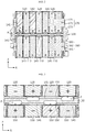
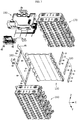
- FIG. 1 is a perspective view showing a multilayer battery module according to an embodiment of the present disclosure
- FIG. 2 is a cross-sectioned view, taken along the line I-I' of FIG. 1
- FIG. 3 is an enlarged view showing a layer boundary portion of first and second cylindrical battery cells of FIG. 2
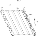
- FIG. 4 is a perspective view showing a heatsink of FIG. 1 .
- a multilayer battery module 100 includes first and second cylindrical battery cells 110, 120, first and second cell housings 160, 170 for respectively accommodating the first and second cylindrical battery cells 110, 120 and vertically coupled to each other, and a heatsink 130 interposed between the first and second cell housings 160, 170.
- the cylindrical battery cells are stacked in two layers.
- the first cylindrical battery cells 110 are disposed on the first layer
- the second cylindrical battery cells 120 are disposed on the second layer.
- the heatsink 130 is located at a layer boundary of the first cylindrical battery cells 110 and the second cylindrical battery cells 120.
- the first and second cylindrical battery cells 110, 120 are conceptually classified according to upper and lower positions thereof, and the first and second cylindrical battery cells 110, 120 have the same configuration.
- the cylindrical battery cell includes, for example, an electrode assembly in a jelly-roll form, a cylindrical battery case for accommodating an electrolyte together with the electrode assembly, a positive electrode terminal formed at a top end of the battery case, a negative electrode terminal formed at a bottom end of the battery case.
- the cylindrical battery cell may be fabricated such that a top cap forming the positive electrode terminal is separated from the battery case or a gas hole is formed at the top cap, so as to prevent the cylindrical battery cell from being exploded since the internal pressure of cylindrical battery cell increases rapidly due to the gas generated in the cell during a charging and discharging process.
- the first cylindrical battery cells 110 may be arranged in lateral and longitudinal directions into a matrix form in a state where the positive electrode terminals and the negative electrode terminals stand up toward an upper side or a lower side (Here, the lateral direction means ⁇ X-axis direction and the longitudinal direction means ⁇ Y-axis direction based on the coordinates shown in each figure).
- first cylindrical battery cells 110 may be arranged such that first cylindrical battery cells neighboring in the lateral direction are reversed and the first cylindrical battery cells neighboring in the longitudinal direction are not reversed.
- the upper and lower portions of the cylindrical battery cells in each row are reversed in the X-axis direction so that the polarities at the top and the bottom thereof are alternately reversed
- the upper and lower portions of the cylindrical battery cells in each column are not reversed in the Y-axis direction so that the polarities at the top and the bottom thereof are identical to each other (see FIGS. 2 and 8 together).
- the second cylindrical battery cells 120 may be disposed on the first cylindrical battery cells 110 and arranged in lateral and longitudinal directions into a matrix form to correspond to the first cylindrical battery cells 110 in one-to-one relationship.
- the second cylindrical battery cells 120 are also arranged such that second cylindrical battery cells neighboring in the lateral direction have different polarities at top and bottom ends thereof and second cylindrical battery cells neighboring in the longitudinal direction have the same polarity at the top and bottom ends thereof, similar to the first cylindrical battery cells 110.
- the first cylindrical battery cells 110 and the second cylindrical battery cells 120 having different polarities are disposed to face each other, based on the heatsink 130 located in the middle of the multilayer battery module 100, namely between the layers the multilayer battery module 100.
- the positive electrode terminal of the first cylindrical battery cell 110 is disposed to vertically face the negative electrode terminal of the second cylindrical battery cell 120
- the negative electrode terminal of the first cylindrical battery cell 110 is disposed to vertically face the positive electrode terminal of the second cylindrical battery cell 120.
- the cylindrical battery cells 110, 120 may be connected in series and/or in parallel more easily, compared to the case where the top and bottom ends of the cylindrical battery cells in each row and column are arranged to have the same polarity.
- a center portion where the first and second cylindrical battery cells 110, 120 face each other namely a layer boundary portion of the first and second cylindrical battery cells 110, 120, has a high heat accumulation rate, and when gas is generated, the gas is not easily discharged, compared to an outer portion.
- the present disclosure is designed to solve this problem by applying the heatsink 130 to the center portion where the first and second cylindrical battery cells 110, 120 face each other, so as to smoothly perform heat dissipation and gas discharge.
- the heatsink 130 may include an uneven portion 131 having an uneven pattern along the lateral direction and having an area corresponding to a lateral and vertical arrangement area of the first and second cylindrical battery cells 110, 120, and a heat dissipation portion 132 having an increased thickness from at least one edge of the uneven portion 131 and exposed out of the layer boundary of the first and second cylindrical battery cells 110, 120.
- the heat dissipation portion 132 is provided at two edges of the uneven portion 131, and a plurality of heat dissipation fins 132a diverged into several branches are provided at the heat dissipation portion 132 to ensure a sufficient heat dissipation area.
- the heatsink 130 may be made of aluminum or aluminum alloy, among metal materials with high thermal conductivity.
- the heatsink 130 of the present disclosure is not limited to aluminum.
- copper, gold or silver may be used, and ceramic materials such as aluminum nitride and silicon carbide other than metal are also available.
- the heat of the cylindrical battery cell is dissipated mainly through the negative electrode terminal, and the heatsink 130 is formed at the top portion of the positive electrode terminal to secure a gas discharge space.
- the uneven portion 131 of the heatsink 130 is provided so that a portion facing each positive electrode terminal of the first and second cylindrical battery cells 110, 120 is convex toward the positive electrode terminal, thereby forming a gas discharge path for discharging gas generated in the cylindrical battery cell. Also, a portion of the uneven portion 131 of the heatsink 130 facing each negative electrode terminal of the first and second cylindrical battery cells 110, 120 may be closely adhered to the negative electrode terminal to form a heat dissipation path leading to the heat dissipation portion 132.
- the gas discharge paths P of each row may communicate with at least one of front and rear surfaces of the battery module 100 along the longitudinal direction (Y-axis direction).
- a BMS housing 190 in which a BMS circuit board and other electrical components are assembled is mounted to a front side of the battery module 100 of this embodiment, and the gas discharge path P communicates with the outside through a rear portion of the battery module 100.
- the uneven portion 131 of the heatsink 130 absorbs the heat generated from the negative electrode terminals of the first and second cylindrical battery cells 110, 120. Since the heat dissipation portion 132 of the heatsink 130 exposed out of the battery module 100 has a relatively lower temperature than the uneven portion 131, the heat absorbed by the uneven portion 131 may be transferred to the heat dissipation portion 132 and discharged to the outside.
- heat transfer pads may be interposed between the first and second cylindrical battery cells 110, 120 and the heatsink 130.
- the heat transfer pad is made of a thermally conductive material and transfers heat between the heatsink 130 and the positive or negative electrode terminal.
- the heat transfer pad may be fixed to the heatsink 130 and the positive or negative electrode terminal by means of an adhesive. By doing so, it is possible to prevent the heat transfer pad from moving, and an air layer between the heat transfer pad and the heatsink 130 or an air layer between the heat transfer pad and the positive or negative electrode terminal may be removed or reduced to increase the heat transfer efficiency.
- the heat transfer pads according to the present disclosure may be disposed at the top end and the bottom end of each of the first and second cylindrical battery cells 110, 120 to cover a part of the positive electrode terminals neighboring in the lateral direction and all of the negative electrode terminals together.
- the heat transfer pads are conceptually classified into a first heat transfer pad 141, a second heat transfer pad 142 and a third heat transfer pad 143 depending on their positions.
- the first to third heat transfer pads 143 are arranged in the same pattern.
- the construction and arrangement of the first heat transfer pad 141 will be described in detail and the second and third heat transfer pad 142, 143 will not be described in detail.
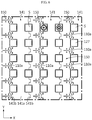
- the positive electrode terminals 110a and the negative electrode terminals located at the top ends of the first cylindrical battery cells 110 may be electrically connected to each other by several metal plates 150 extending in the longitudinal direction.
- the metal plate 150 is an electrically conductive component made of copper or aluminum that electrically connects the cylindrical battery cells, and the metal plate 150 is attached to partially cover the positive electrode terminals 110a and the negative electrode terminals.
- the first heat transfer pad 141 may be alternately arranged with the metal plates 150 along the X-axis direction to cover the upper portions of the positive electrode terminals 110a and the negative electrode terminals. In other words, the first heat transfer pad 141 may cover the entire area of the negative electrode terminal and cover only the edge area of the neighboring positive electrode terminal 110a.
- the first heat transfer pad 141 may include a strap portion 141a extended by a longitudinal arrangement length of the cylindrical battery cells and branch portions 141b extending at the strap portion 141a in left and right direction at predetermined intervals.
- the strap portion 141a covers the upper portion of all negative electrode terminals along the longitudinal direction, and the branch portions 141b cover a part of the edges of the positive electrode terminals adjacent to each negative electrode terminal in the left and right directions.
- the first heat transfer pad 141 not only the negative electrode terminal but also a part of the edge of the positive electrode terminal 110a may contact the first heat transfer pad 141, so that the heat of the first and second cylindrical battery cells 110, 120 may be rapidly conducted from the positive electrode terminal and the negative electrode terminal to the heatsink 130 via the first heat transfer pad 141.
- gas since the upper portions of the positive electrode terminals are not completely covered by the first heat transfer pad 141 and the metal plate 150, gas may be discharged from the positive electrode terminal at emergency.
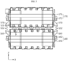
- the multilayer battery module 100 may further include a first cell housing 160 made of upper and lower cases configured to be vertically coupled to each other to respectively surround the peripheries of the first cylindrical battery cells 110, and a second cell housing 170 made upper and lower cases configured to be vertically coupled to each other to respectively surround the peripheries of the second cylindrical battery cells 120.
- the first and second cell housings 160, 170 may be symmetrically coupled with each other with the heatsink 130 being interposed therebetween.
- the uneven portion 131 of the heatsink 130 has an uneven structure in the X-axis direction
- the heatsink 130 is disposed horizontal to the top surface of the first cell housing 160 and the bottom surface of the second cell housing 170
- the top portion and the bottom portion of the uneven portion 131 are covered to form a long heat and gas discharge path P in the Y-axis direction.
- the heat and gas discharge path P is partitioned into several separate compartments by the uneven portion 131 of the heatsink 130, the upper surface of the first cell housing 160, and the lower surface of the second cell housing 170.
- the gas discharge paths P of each row may communicate with at least one of the front surface and the rear surface of the battery module 100 along the longitudinal direction (Y-axis direction) based on the first and second cylindrical battery cells 110, 120.
- the battery module 100 of this embodiment is configured such that a BMS circuit board and other electrical components are mounted to the front side thereof and the gas discharge path P communicates with the outside through the rear side thereof.
- the heat dissipation portion 132 of the heatsink 130 may be exposed to the outside at both side surfaces of the first and second cell housings 160, 170.
- the first and second cell housings 160, 170 may be connected into a single body by a coupling plate 180.
- the heat dissipation portion 132 of the heatsink 130 may be provided in plural, and the plurality of heat dissipation portions 132 may be discontinuous along the longitudinal direction (Y-axis direction) of the heatsink 130.
- the coupling plate 180 may be vertically disposed between the heat dissipation portions 132 and fixed to the first and second cell housings 160, 170 by a fastening means such as a screw or a bolt.
- the coupling plate 180 may be fixedly mounted to both side surfaces of the first and second cell housings 160, 170, respectively.
- the first and second cell housings 160, 170 may be strongly restrained, and also the heatsink 130 located between the first and second cell housings 160, 170 may not move at all in the upper, lower, left and right directions.
- first and second cell housings 160, 170 may further include side protrusions 163, 173 respectively formed to protrude from the side surfaces thereof to press the heat dissipation portion 132 of the heatsink 130 in a vertical direction.
- the heat dissipation portion 132 of the heatsink 130 exposed to the outside may be compressed by the side protrusions 163, 173 of the first and second cell housings 160, 170 not to move.
- the side protrusions 163, 173 of the first and second cell housings 160, 170 and the heat dissipation portion 132 of the heatsink 130 may be integrally fixed to each other by vertically fastening a bolt or screw.
- the heatsink 130 may be firmly fixed to the first and second cell housings 160, 170 by the coupling plate 180 disposed between the heat dissipation portions 132 of the heatsink 130 and the side protrusions 163, 173 pressing the top and bottom portions of the heat dissipation portion 132 of the heatsink 130.
- the first and second cell housings 160, 170 may respectively include upper cases 161, 171 and lower cases 162, 172, which may be vertically coupled to each other.
- the upper and lower cases 161, 171, 162, 172 surround the outer surfaces of the cylindrical battery cells, and the top and bottom ends thereof may be exposed to the outside.
- the upper and lower cases 161, 171, 162, 172 may include cell holders capable of inserting individual cylindrical battery cells therein and may be vertically coupled to each other to surround the outer surfaces of the cylindrical battery cells.
- top end of the upper case 161, 171 and the bottom end of the lower case 162, 172 may have rectangular pieces S which may support the cylindrical battery cells without separating from the cell holder when the cylindrical battery cells are inserted.
- the multilayer battery module 100 may further include various devices for controlling charge and discharge of the first and second cylindrical battery cells 110, 120, for example a BMS, a current sensor, a fuse, and the like.
- the multilayer battery pack 10 includes the multilayer battery module 100 described above and a pack case 200 configured to package the multilayer battery module 100 therein.
- the multilayer battery pack 10 of this embodiment is designed to include one multilayer battery module 100, but the present disclosure is not necessarily limited thereto.
- the multilayer battery pack 10 may include two or more multilayer battery modules 100 stacked vertically and/or horizontally.
- the pack case 200 of this embodiment includes a case body 210, and a case upper plate 220 and a case lower plate 230 for covering an upper portion and a lower portion of the case body 210.
- the case body 210 may have a substantially tetrahedral shape that integrally surrounds the entire side periphery of the multilayer battery module 100 with a size corresponding to the volume of the multilayer battery module 100.
- a positive electrode terminal, a negative electrode terminal and other communication ports may be provided at the front surface of the case body 210, and a gas venting hole 211 may be provided at the rear surface of the case body 210. The heat or gas emitted from the multilayer battery module 100 may be discharged out of the battery pack 10 through the gas venting hole 211.
- the gas venting hole 211 may be provided at a height where the heatsink 130 is located when the multilayer battery module 100 is accommodated in the pack case 200.
- the gas venting hole 211 is provided at the same height as the heat and gas discharge path P, which communicates with the outside through the rear surface of the multilayer battery module 100, at the inside of the multilayer battery module 100.
- the gas venting hole 211 faces the heat and gas discharge path P of the battery module 100 at the same height, the gas may be discharged out of the battery pack 10 more smoothly.
- the inner surface of the case upper plate 220 is separated from and convex toward the positive electrode terminal located at the top end of the second cylindrical battery cells 120 and is closely adhered to the negative electrode terminal.
- the heat and gas discharge path P may also be formed at the upper portion of the second cylindrical battery cell 120, similar to the layer boundary of the first and second cylindrical battery cells 110, 120.
- a second heat transfer pad 142 may be additionally attached to the case upper plate 220 that is in contact with the negative electrode terminals, in order to increase the thermal conductivity from the negative electrode terminals.
- the case lower plate 230 has a structure similar to the case upper plate 220.
- the inner surface of the case lower plate 230 is separated from and convex toward the positive electrode terminal located at the bottom end of the first cylindrical battery cells 110 and is closely adhered to the negative electrode terminal.
- the heat and gas discharge path P may also be formed at the lower portion of the first cylindrical battery cell 110, similar to the layer boundary of the first and second cylindrical battery cells 110, 120.
- a second heat transfer pad 142 may be additionally attached to the case upper plate 220 that is in contact with the negative electrode terminals, in order to increase the thermal conductivity from the negative electrode terminals.
- the case upper plate 220 and the case lower plate 230 may be used to secure the heat dissipation and gas discharge space, similar to the heatsink 130 described above, together with the function of protecting the battery module from external impacts.
- the case upper plate 220 and the case lower plate 230 may be preferably made of a metal material with excellent mechanical rigidity and excellent thermal conductivity.
Landscapes
- Chemical & Material Sciences (AREA)
- Chemical Kinetics & Catalysis (AREA)
- Electrochemistry (AREA)
- General Chemical & Material Sciences (AREA)
- Engineering & Computer Science (AREA)
- Manufacturing & Machinery (AREA)
- Battery Mounting, Suspending (AREA)
- Secondary Cells (AREA)
- Gas Exhaust Devices For Batteries (AREA)
Abstract
Description
- The present disclosure relates to a cylindrical secondary battery module, and more particularly, to a multilayer cylindrical secondary battery module having a heat dissipation and chain ignition prevention structure for cylindrical secondary batteries arranged in a layered form.
- The present application claims priority to Korean Patent Application No.
10-2018-0005920 filed on January 17, 2018 - A secondary battery may be classified into a can-type secondary battery in which an electrode assembly is included in a metal can and a pouch-type secondary battery in which an electrode assembly is included in a pouch made of an aluminum sheet, depending on the shape of the exterior. Here, the can-type secondary battery may also be classified into a cylindrical battery and a rectangular battery depending on the shape of the metal can.
- The pouch-type secondary battery has advantages of easy stacking and high energy density, but it is vulnerable to an external impact due to low mechanical rigidity. Meanwhile, the can-type secondary battery is evaluated as being better than the pouch-type secondary battery in terms of safety due to good durability. Thus, the cylindrical secondary batteries are widely used in a battery module or a battery pack applied to environment-friendly electric vehicles in addition to the pouch-type secondary batteries.
- However, in the cylindrical secondary batteries, heat is generated in the charging and discharging process because the charging and discharging process is performed by electrochemical reaction. At this time, if heat is not properly dissipated, the cylindrical secondary batteries may be degraded faster and, in some cases, ignition or explosion may occur. Here, if any one of the cylindrical secondary batteries is exploded, the explosion may cause a series explosion of other neighboring cylindrical secondary batteries. Thus, heat dissipation of the cylindrical secondary battery is very important especially for the secondary battery module to which the multilayer assembly method is applied.
- In general, the cylindrical secondary battery has a current interruptive device (CID) and a safety vent for interrupting the current during abnormal operation of the battery and for relieving the internal pressure, which are mounted in the space between an electrode assembly and a top cap of a positive electrode terminal. Here, the safety vent is generally installed at the positive electrode terminal of the secondary battery. When the internal pressure of the secondary battery increases, the safety vent protrudes and ruptures to exhausts the gas. In other words, when the battery operates abnormally, gas is discharged toward the positive electrode terminal at which the safety vent is installed.
- The heat dissipation and gas discharge structure of the conventional multilayer cylindrical secondary battery pack is as follows in consideration of the above characteristics of the cylindrical secondary battery. For example, the cylindrical secondary batteries are separated into layers to include a first cylindrical secondary battery group arranged in the first layer and a second cylindrical secondary battery group arranged in the second layer. At this time, the cylindrical secondary batteries are arranged in two patterns. In the first pattern, positive electrode terminals of the first and second cylindrical secondary battery groups face each other based on the center portion thereof, and negative electrode terminals are arranged at an uppermost end or a lowermost end. In the second pattern, the negative electrode terminals of the first and second cylindrical secondary battery groups face each other based on the center portion thereof, and the positive electrode terminals are arranged at the uppermost end or the lowermost end.
- In the first pattern, the heat dissipation structure is applied to the negative electrode terminal located at the uppermost end and the lowermost end to facilitate heat dissipation to the outside. However, if the heat dissipation structure is applied to the positive electrode terminals facing each other in a vertical direction in a middle region, it is difficult to secure a gas discharge space for preventing chain ignition.
- In the second pattern, a cooling plate is installed between the negative electrode terminals facing each other in a vertical direction in a middle region, and the heat is discharged to the outside through the cooling plate. Here, a gas discharge space may be easily secured at the positive electrode terminal located at the uppermost end and the lowermost end, but it is difficult to add the heat dissipation structure thereto.
- In addition, in case of a multilayer battery module having the conventional heat dissipation and gas discharge space securing structure as described above, the negative electrode terminals of the first and second cylindrical secondary battery groups should face each other or face in the opposite direction. In this case, the electrical connection structure between the batteries becomes complicated. Thus, there is a need for a method of effectively securing the heat dissipation and gas discharge space even when the cylindrical secondary batteries layered in a vertical direction are arranged so that terminals having different polarities face each other in a middle region, unlike the conventional case.
- The present disclosure is designed to solve the problems of the related art, and therefore the present disclosure is directed to providing a multilayer battery module, in which a heat dissipation and chain ignition prevention structure is applied to a cylindrical battery cell assembly where positive electrode terminals and negative electrode terminals are arranged to face each other in a vertical direction with space efficiency, and a battery pack including the multilayer battery module.
- In one aspect of the present disclosure, there is provided a multilayer battery module, comprising: first cylindrical battery cells disposed to stand up and arranged in lateral and longitudinal directions into a matrix form; second cylindrical battery cells disposed to stand up and arranged on the first cylindrical battery cells in one-to-one relationship; and a heatsink made of a material with high thermal conductivity and disposed at a layer boundary between the first cylindrical battery cells and the second cylindrical battery cells, wherein the first cylindrical battery cells and the second cylindrical battery cells are disposed so that positive electrode terminals thereof and negative electrode terminals thereof face each other with the heatsink being interposed therebetween, wherein a portion of the heatsink facing the positive electrode terminal is convex toward the positive electrode terminal to form a heat and gas discharge path, and a portion of the heatsink facing the negative electrode terminal is closely adhered to the negative electrode terminal to form a heat dissipation path.
- The first and second cylindrical battery cells may be arranged so that upper and lower portions of first and second cylindrical battery cells neighboring along a lateral direction are reversed and upper and lower portions of first and second cylindrical battery cells neighboring along a longitudinal direction are not reversed.
- The heatsink may include an uneven portion having an uneven pattern along the lateral direction and having an area corresponding to a lateral and longitudinal arrangement area of the first and second cylindrical battery cells; and a heat dissipation portion having an increased thickness in a vertical direction from at least one edge of the uneven portion and exposed out of the layer boundary of the first and second cylindrical battery cells.
- The multilayer battery module may further comprise a plurality of heat transfer pads disposed at top ends and bottom ends of the first and second cylindrical battery cells, respectively, to cover all of negative electrode terminals and a part of positive electrode terminals neighboring in the lateral direction.
- The multilayer battery module may further comprise a first cell housing formed to surround a periphery of each of the first cylindrical battery cells; and a second cell housing vertically coupled to the first cell housing with the heatsink being interposed therebetween, the second cell housing being formed to surround a periphery of each of the second cylindrical battery cells.
- The heat and gas discharge path may be partitioned into several separate compartments by the uneven portion of the heatsink, an upper surface of the first cell housing and a lower surface of the second cell housing.
- The heat dissipation portion may be provided in plural so that the plurality of heat dissipation portions are discontinuous along a longitudinal direction of the heatsink, and the multilayer battery module may further comprise a coupling plate disposed vertically between the heat dissipation portions and coupled to side surfaces of the first cell housing and the second cell housing.
- The first cell housing and the second cell housing may include side protrusions respectively formed to protrude from side surfaces thereof to compress the heat dissipation portion in the vertical direction.
- In another aspect of the present disclosure, there is also provided a multilayer battery pack, comprising: the multilayer battery module described above; and a pack case configured to accommodate the multilayer battery module, wherein the pack case includes a case body configured to integrally surround a side periphery of the multilayer battery module; and a case upper plate and a case lower plate respectively coupled to a top end and a bottom end of the case body to cover an upper portion and a lower portion of the multilayer battery module.
- An inner surface of the case upper plate may be separated from and convex toward the positive electrode terminals located at top ends of the second cylindrical battery cells and is closely adhered to the negative electrode terminals of the second cylindrical battery cells, and an inner surface of the case lower plate may be separated from and convex toward the positive electrode terminals located at bottom ends of the first cylindrical battery cells and is closely adhered to the negative electrode terminals of the first cylindrical battery cells.
- The case body may have a gas venting hole formed at a height where the heatsink is located.
- The multilayer battery module according to the present disclosure may have a heat dissipation and gas discharge space to easily discharge the heat and gas generated from the cylindrical battery cells to a layer boundary at which the positive electrode terminals and the negative electrode terminals face each other in a vertical direction.
- Thus, even though heat and gas are generated in any one of the cylindrical battery cells concentrated in a narrow space, it is possible to prevent other neighboring cylindrical battery cells from being ignited or exploded in a chain.
-
-
FIG. 1 is a perspective view showing a multilayer battery module according to an embodiment of the present disclosure. -
FIG. 2 is a cross-sectioned view, taken along the line I-I' ofFIG. 1 . -
FIG. 3 is an enlarged view showing a layer boundary portion of first and second cylindrical battery cells ofFIG. 2 . -
FIG. 4 is a perspective view showing a heatsink ofFIG. 1 . -
FIG. 5 is a rear view ofFIG. 1 . -
FIG. 6 is a diagram showing a portion of a top end of the first cylindrical battery cells according to an embodiment of the present disclosure. -
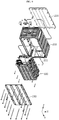
FIG. 7 is an exploded perspective view ofFIG. 1 . -
FIG. 8 is an exploded perspective view showing a first cell housing ofFIG. 7 . -
FIG. 9 is an exploded perspective view showing a multilayer battery pack according to an embodiment of the present disclosure. -
FIG. 10 is a perspective view showing the multilayer battery pack ofFIG. 9 in an assembled state. -
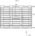
FIG. 11 is a rear view ofFIG. 10 . -
FIG. 12 is a cross-sectioned view, taken along the line II-II' ofFIG. 10 . - Hereinafter, preferred embodiments of the present disclosure will be described in detail with reference to the accompanying drawings. Prior to the description, it should be understood that the terms used in the specification and the appended claims should not be construed as limited to general and dictionary meanings, but interpreted based on the meanings and concepts corresponding to technical aspects of the present disclosure on the basis of the principle that the inventor is allowed to define terms appropriately for the best explanation.
- Therefore, the description proposed herein is just a preferable example for the purpose of illustrations only, not intended to limit the scope of the disclosure, so it should be understood that other equivalents and modifications could be made thereto without departing from the scope of the disclosure.
-
FIG. 1 is a perspective view showing a multilayer battery module according to an embodiment of the present disclosure,FIG. 2 is a cross-sectioned view, taken along the line I-I' ofFIG. 1 ,FIG. 3 is an enlarged view showing a layer boundary portion of first and second cylindrical battery cells ofFIG. 2 , andFIG. 4 is a perspective view showing a heatsink ofFIG. 1 . - Referring to these figures, a
multilayer battery module 100 according to an embodiment of the present disclosure includes first and secondcylindrical battery cells second cell housings cylindrical battery cells heatsink 130 interposed between the first andsecond cell housings - The cylindrical battery cells are stacked in two layers. Here, it may be understood that the first
cylindrical battery cells 110 are disposed on the first layer, and the secondcylindrical battery cells 120 are disposed on the second layer. In addition, theheatsink 130 is located at a layer boundary of the firstcylindrical battery cells 110 and the secondcylindrical battery cells 120. - The first and second
cylindrical battery cells cylindrical battery cells - In this embodiment, the cylindrical battery cell may be fabricated such that a top cap forming the positive electrode terminal is separated from the battery case or a gas hole is formed at the top cap, so as to prevent the cylindrical battery cell from being exploded since the internal pressure of cylindrical battery cell increases rapidly due to the gas generated in the cell during a charging and discharging process.
- Referring to
FIGS. 2 and8 together, the firstcylindrical battery cells 110 may be arranged in lateral and longitudinal directions into a matrix form in a state where the positive electrode terminals and the negative electrode terminals stand up toward an upper side or a lower side (Here, the lateral direction means ±X-axis direction and the longitudinal direction means ±Y-axis direction based on the coordinates shown in each figure). - More specifically, the first
cylindrical battery cells 110 may be arranged such that first cylindrical battery cells neighboring in the lateral direction are reversed and the first cylindrical battery cells neighboring in the longitudinal direction are not reversed. For example, the upper and lower portions of the cylindrical battery cells in each row are reversed in the X-axis direction so that the polarities at the top and the bottom thereof are alternately reversed, and the upper and lower portions of the cylindrical battery cells in each column are not reversed in the Y-axis direction so that the polarities at the top and the bottom thereof are identical to each other (seeFIGS. 2 and8 together). - The second
cylindrical battery cells 120 may be disposed on the firstcylindrical battery cells 110 and arranged in lateral and longitudinal directions into a matrix form to correspond to the firstcylindrical battery cells 110 in one-to-one relationship. In addition, the secondcylindrical battery cells 120 are also arranged such that second cylindrical battery cells neighboring in the lateral direction have different polarities at top and bottom ends thereof and second cylindrical battery cells neighboring in the longitudinal direction have the same polarity at the top and bottom ends thereof, similar to the firstcylindrical battery cells 110. - At this time, the first
cylindrical battery cells 110 and the secondcylindrical battery cells 120 having different polarities are disposed to face each other, based on theheatsink 130 located in the middle of themultilayer battery module 100, namely between the layers themultilayer battery module 100. For example, in each row, the positive electrode terminal of the firstcylindrical battery cell 110 is disposed to vertically face the negative electrode terminal of the secondcylindrical battery cell 120, and the negative electrode terminal of the firstcylindrical battery cell 110 is disposed to vertically face the positive electrode terminal of the secondcylindrical battery cell 120. - If the first and second
cylindrical battery cells - Meanwhile, in the general
multilayer battery module 100, a center portion where the first and secondcylindrical battery cells cylindrical battery cells heatsink 130 to the center portion where the first and secondcylindrical battery cells - As shown in
FIG. 4 , theheatsink 130 may include anuneven portion 131 having an uneven pattern along the lateral direction and having an area corresponding to a lateral and vertical arrangement area of the first and secondcylindrical battery cells heat dissipation portion 132 having an increased thickness from at least one edge of theuneven portion 131 and exposed out of the layer boundary of the first and secondcylindrical battery cells heat dissipation portion 132 is provided at two edges of theuneven portion 131, and a plurality ofheat dissipation fins 132a diverged into several branches are provided at theheat dissipation portion 132 to ensure a sufficient heat dissipation area. - The
heatsink 130 may be made of aluminum or aluminum alloy, among metal materials with high thermal conductivity. Theheatsink 130 of the present disclosure is not limited to aluminum. For example, copper, gold or silver may be used, and ceramic materials such as aluminum nitride and silicon carbide other than metal are also available. - For reference, since heat is generated greatest at the electrode terminal during charging and discharging, it is effective to cool the positive electrode terminal and the negative electrode terminal of the cylindrical battery cell. However, if the positive electrode terminal is covered with the
heat dissipation portion 132, the gas generated in the cylindrical battery cell may not be smoothly discharged, and thus the cylindrical battery cell may be highly likely to be exploded due to the increased pressure. Thus, in the present disclosure, the heat of the cylindrical battery cell is dissipated mainly through the negative electrode terminal, and theheatsink 130 is formed at the top portion of the positive electrode terminal to secure a gas discharge space. - Specifically, the
uneven portion 131 of theheatsink 130 is provided so that a portion facing each positive electrode terminal of the first and secondcylindrical battery cells uneven portion 131 of theheatsink 130 facing each negative electrode terminal of the first and secondcylindrical battery cells heat dissipation portion 132. - As shown in
FIG. 5 , the gas discharge paths P of each row may communicate with at least one of front and rear surfaces of thebattery module 100 along the longitudinal direction (Y-axis direction). For example, aBMS housing 190 in which a BMS circuit board and other electrical components are assembled is mounted to a front side of thebattery module 100 of this embodiment, and the gas discharge path P communicates with the outside through a rear portion of thebattery module 100. - In addition, the
uneven portion 131 of theheatsink 130 absorbs the heat generated from the negative electrode terminals of the first and secondcylindrical battery cells heat dissipation portion 132 of theheatsink 130 exposed out of thebattery module 100 has a relatively lower temperature than theuneven portion 131, the heat absorbed by theuneven portion 131 may be transferred to theheat dissipation portion 132 and discharged to the outside. - At this time, in order to improve the thermal conductivity, heat transfer pads may be interposed between the first and second
cylindrical battery cells heatsink 130. The heat transfer pad is made of a thermally conductive material and transfers heat between theheatsink 130 and the positive or negative electrode terminal. - The heat transfer pad may be fixed to the
heatsink 130 and the positive or negative electrode terminal by means of an adhesive. By doing so, it is possible to prevent the heat transfer pad from moving, and an air layer between the heat transfer pad and theheatsink 130 or an air layer between the heat transfer pad and the positive or negative electrode terminal may be removed or reduced to increase the heat transfer efficiency. - The heat transfer pads according to the present disclosure may be disposed at the top end and the bottom end of each of the first and second
cylindrical battery cells - The heat transfer pads are conceptually classified into a first
heat transfer pad 141, a secondheat transfer pad 142 and a thirdheat transfer pad 143 depending on their positions. Here, the first to thirdheat transfer pads 143 are arranged in the same pattern. Thus, the construction and arrangement of the firstheat transfer pad 141 will be described in detail and the second and thirdheat transfer pad - For example, referring to
FIGS. 2 to 3 and6 to 8 together, thepositive electrode terminals 110a and the negative electrode terminals located at the top ends of the firstcylindrical battery cells 110 may be electrically connected to each other byseveral metal plates 150 extending in the longitudinal direction. Here, themetal plate 150 is an electrically conductive component made of copper or aluminum that electrically connects the cylindrical battery cells, and themetal plate 150 is attached to partially cover thepositive electrode terminals 110a and the negative electrode terminals. - The first
heat transfer pad 141 may be alternately arranged with themetal plates 150 along the X-axis direction to cover the upper portions of thepositive electrode terminals 110a and the negative electrode terminals. In other words, the firstheat transfer pad 141 may cover the entire area of the negative electrode terminal and cover only the edge area of the neighboringpositive electrode terminal 110a. - More specifically, the first
heat transfer pad 141 may include astrap portion 141a extended by a longitudinal arrangement length of the cylindrical battery cells andbranch portions 141b extending at thestrap portion 141a in left and right direction at predetermined intervals. - The
strap portion 141a covers the upper portion of all negative electrode terminals along the longitudinal direction, and thebranch portions 141b cover a part of the edges of the positive electrode terminals adjacent to each negative electrode terminal in the left and right directions. - If the first
heat transfer pad 141 is used, not only the negative electrode terminal but also a part of the edge of thepositive electrode terminal 110a may contact the firstheat transfer pad 141, so that the heat of the first and secondcylindrical battery cells heatsink 130 via the firstheat transfer pad 141. In addition, since the upper portions of the positive electrode terminals are not completely covered by the firstheat transfer pad 141 and themetal plate 150, gas may be discharged from the positive electrode terminal at emergency. - Referring to
FIGS. 1 ,2 ,5 and7 again, themultilayer battery module 100 according to the present disclosure may further include afirst cell housing 160 made of upper and lower cases configured to be vertically coupled to each other to respectively surround the peripheries of the firstcylindrical battery cells 110, and asecond cell housing 170 made upper and lower cases configured to be vertically coupled to each other to respectively surround the peripheries of the secondcylindrical battery cells 120. In addition, the first andsecond cell housings heatsink 130 being interposed therebetween. - Since the
uneven portion 131 of theheatsink 130 has an uneven structure in the X-axis direction, when theheatsink 130 is disposed horizontal to the top surface of thefirst cell housing 160 and the bottom surface of thesecond cell housing 170, the top portion and the bottom portion of theuneven portion 131 are covered to form a long heat and gas discharge path P in the Y-axis direction. At this time, the heat and gas discharge path P is partitioned into several separate compartments by theuneven portion 131 of theheatsink 130, the upper surface of thefirst cell housing 160, and the lower surface of thesecond cell housing 170. For example, the gas discharge paths P of each row may communicate with at least one of the front surface and the rear surface of thebattery module 100 along the longitudinal direction (Y-axis direction) based on the first and secondcylindrical battery cells battery module 100 of this embodiment is configured such that a BMS circuit board and other electrical components are mounted to the front side thereof and the gas discharge path P communicates with the outside through the rear side thereof. - In this case, even though the positive electrode terminal of any one cylindrical battery cell is broken to generate heat and gas, the heat and gas may be quickly discharged out of the battery module. Also, since the upper and lower portions and the left and right portions of the battery module are partially blocked the
heatsink 130, it is possible to minimize the effect applied to other cylindrical battery cells. - The
heat dissipation portion 132 of theheatsink 130 may be exposed to the outside at both side surfaces of the first andsecond cell housings second cell housings coupling plate 180. - The
heat dissipation portion 132 of theheatsink 130 may be provided in plural, and the plurality ofheat dissipation portions 132 may be discontinuous along the longitudinal direction (Y-axis direction) of theheatsink 130. Thecoupling plate 180 may be vertically disposed between theheat dissipation portions 132 and fixed to the first andsecond cell housings coupling plate 180 may be fixedly mounted to both side surfaces of the first andsecond cell housings - According to this coupling configuration, the first and
second cell housings heatsink 130 located between the first andsecond cell housings - In addition, the first and
second cell housings side protrusions heat dissipation portion 132 of theheatsink 130 in a vertical direction. - As shown in
FIG. 5 , theheat dissipation portion 132 of theheatsink 130 exposed to the outside may be compressed by theside protrusions second cell housings side protrusions second cell housings heat dissipation portion 132 of theheatsink 130 may be integrally fixed to each other by vertically fastening a bolt or screw. - As described above, the
heatsink 130 may be firmly fixed to the first andsecond cell housings coupling plate 180 disposed between theheat dissipation portions 132 of theheatsink 130 and theside protrusions heat dissipation portion 132 of theheatsink 130. - Meanwhile, as shown in
FIG. 8 , the first andsecond cell housings upper cases lower cases - The upper and
lower cases lower cases - In addition, the top end of the
upper case lower case - In addition to the above components, the
multilayer battery module 100 may further include various devices for controlling charge and discharge of the first and secondcylindrical battery cells - Subsequently, referring to
FIGS. 9 to 12 , amultilayer battery pack 10 will be described. Themultilayer battery pack 10 according to an embodiment of the present disclosure includes themultilayer battery module 100 described above and apack case 200 configured to package themultilayer battery module 100 therein. For reference, themultilayer battery pack 10 of this embodiment is designed to include onemultilayer battery module 100, but the present disclosure is not necessarily limited thereto. For example, unlike this embodiment, themultilayer battery pack 10 may include two or moremultilayer battery modules 100 stacked vertically and/or horizontally. - The
pack case 200 of this embodiment includes acase body 210, and a caseupper plate 220 and a caselower plate 230 for covering an upper portion and a lower portion of thecase body 210. - The
case body 210 may have a substantially tetrahedral shape that integrally surrounds the entire side periphery of themultilayer battery module 100 with a size corresponding to the volume of themultilayer battery module 100. A positive electrode terminal, a negative electrode terminal and other communication ports may be provided at the front surface of thecase body 210, and agas venting hole 211 may be provided at the rear surface of thecase body 210. The heat or gas emitted from themultilayer battery module 100 may be discharged out of thebattery pack 10 through thegas venting hole 211. - The
gas venting hole 211 may be provided at a height where theheatsink 130 is located when themultilayer battery module 100 is accommodated in thepack case 200. For example, as shown inFIGS. 9 and11 , thegas venting hole 211 is provided at the same height as the heat and gas discharge path P, which communicates with the outside through the rear surface of themultilayer battery module 100, at the inside of themultilayer battery module 100. In this case, since thegas venting hole 211 faces the heat and gas discharge path P of thebattery module 100 at the same height, the gas may be discharged out of thebattery pack 10 more smoothly. - In addition, as shown in
FIG. 12 , when the caseupper plate 220 is mounted to thecase body 210, the inner surface of the caseupper plate 220 is separated from and convex toward the positive electrode terminal located at the top end of the secondcylindrical battery cells 120 and is closely adhered to the negative electrode terminal. - Thus, the heat and gas discharge path P may also be formed at the upper portion of the second
cylindrical battery cell 120, similar to the layer boundary of the first and secondcylindrical battery cells heat transfer pad 142 may be additionally attached to the caseupper plate 220 that is in contact with the negative electrode terminals, in order to increase the thermal conductivity from the negative electrode terminals. - The case
lower plate 230 has a structure similar to the caseupper plate 220. When the caselower plate 230 is mounted to thecase body 210, the inner surface of the caselower plate 230 is separated from and convex toward the positive electrode terminal located at the bottom end of the firstcylindrical battery cells 110 and is closely adhered to the negative electrode terminal. Thus, the heat and gas discharge path P may also be formed at the lower portion of the firstcylindrical battery cell 110, similar to the layer boundary of the first and secondcylindrical battery cells heat transfer pad 142 may be additionally attached to the caseupper plate 220 that is in contact with the negative electrode terminals, in order to increase the thermal conductivity from the negative electrode terminals. - That is, the case
upper plate 220 and the caselower plate 230 according to the present disclosure may be used to secure the heat dissipation and gas discharge space, similar to theheatsink 130 described above, together with the function of protecting the battery module from external impacts. Thus, the caseupper plate 220 and the caselower plate 230 may be preferably made of a metal material with excellent mechanical rigidity and excellent thermal conductivity. - The present disclosure has been described in detail. However, it should be understood that the detailed description and specific examples, while indicating preferred embodiments of the disclosure, are given by way of illustration only, since various changes and modifications within the scope of the disclosure will become apparent to those skilled in the art from this detailed description.
- Meanwhile, when the terms indicating up, down, left, right, front and rear directions are used in the specification, it is obvious to those skilled in the art that these merely represent relative locations for convenience in explanation and may vary based on a location of an observer or an object to be observed.
Claims (11)
- A multilayer battery module, comprising:first cylindrical battery cells disposed to stand up and arranged in lateral and longitudinal directions into a matrix form;second cylindrical battery cells disposed to stand up and arranged on the first cylindrical battery cells in a one-to-one relationship; anda heatsink made of a material with high thermal conductivity and disposed at a layer boundary between the first cylindrical battery cells and the second cylindrical battery cells,wherein the first cylindrical battery cells and the second cylindrical battery cells are disposed so that positive electrode terminals thereof and negative electrode terminals thereof face each other with the heatsink being interposed therebetween for each corresponding ones of the first and second cylindrical battery cells,wherein a portion of the heatsink facing the each respective positive electrode terminal is recessed to form a heat and gas discharge path, and a portion of the heatsink facing the each negative electrode terminal contacts to the respective negative electrode terminal to form a heat dissipation path.
- The multilayer battery module according to claim 1,
wherein the first and second cylindrical battery cells are arranged so that upper and lower portions of first and second cylindrical battery cells neighboring along a lateral direction are reversed and upper and lower portions of first and second cylindrical battery cells neighboring along a longitudinal direction are not reversed. - The multilayer battery module according to claim 2,
wherein the heatsink includes:an uneven portion having an uneven pattern along the lateral direction and having an area corresponding to a lateral and longitudinal arrangement area of the first and second cylindrical battery cells; anda heat dissipation portion having an increased thickness in a vertical direction from at least one edge of the uneven portion and exposed out of the layer boundary of the first and second cylindrical battery cells. - The multilayer battery module according to claim 2, further comprising:
a plurality of heat transfer pads disposed at top ends and bottom ends of the first and second cylindrical battery cells, respectively, to cover all of the negative electrode terminals and a part of the positive electrode terminals. - The multilayer battery module according to claim 3, further comprising:a first cell housing formed to surround a periphery of each of the first cylindrical battery cells; anda second cell housing vertically coupled to the first cell housing with the heatsink being interposed therebetween, the second cell housing being formed to surround a periphery of each of the second cylindrical battery cells.
- The multilayer battery module according to claim 5,
wherein the heat and gas discharge path is partitioned into several separate compartments by the uneven portion of the heatsink, an upper surface of the first cell housing and a lower surface of the second cell housing. - The multilayer battery module according to claim 5,
wherein the heat dissipation portion is provided in plural, and the plurality of heat dissipation portions are discontinuous along a longitudinal direction of the heatsink, and
wherein the multilayer battery module further comprises a coupling plate disposed vertically between the heat dissipation portions and coupled to side surfaces of the first cell housing and the second cell housing. - The multilayer battery module according to claim 5,
wherein the first cell housing and the second cell housing include side protrusions respectively formed to protrude from side surfaces thereof to compress the heat dissipation portion in the vertical direction. - A multilayer battery pack, comprising:a multilayer battery module defined in any one of claims 1 to 8; anda pack case configured to accommodate the multilayer battery module,wherein the pack case includes:a case body configured to integrally surround a side periphery of the multilayer battery module; anda case upper plate and a case lower plate respectively coupled to a top end and a bottom end of the case body to cover an upper portion and a lower portion of the multilayer battery module.
- The multilayer battery pack according to claim 9,
wherein an inner surface of the case upper plate is separated from and convex toward the positive electrode terminals located at top ends of the second cylindrical battery cells and contacts the negative electrode terminals of the second cylindrical battery cells, and
wherein an inner surface of the case lower plate is separated from the positive electrode terminals located at bottom ends of the first cylindrical battery cells and contacts the negative electrode terminals of the first cylindrical battery cells. - The multilayer battery pack according to claim 10,
wherein the case body has a gas venting hole formed at a height where the heatsink is located.
Applications Claiming Priority (2)
| Application Number | Priority Date | Filing Date | Title |
|---|---|---|---|
| KR1020180005920A KR102263763B1 (en) | 2018-01-17 | 2018-01-17 | Mfultilayer cylindrical battery module with heat dissipation and chain ignition prevention structure and Battery Pack including the same |
| PCT/KR2019/000293 WO2019143060A1 (en) | 2018-01-17 | 2019-01-08 | Multilayered cylindrical battery module having heat dissipation and chain ignition preventing structure and battery pack comprising same |
Publications (3)
| Publication Number | Publication Date |
|---|---|
| EP3641048A1 true EP3641048A1 (en) | 2020-04-22 |
| EP3641048A4 EP3641048A4 (en) | 2020-11-11 |
| EP3641048B1 EP3641048B1 (en) | 2023-10-18 |
Family
ID=67301499
Family Applications (1)
| Application Number | Title | Priority Date | Filing Date |
|---|---|---|---|
| EP19741550.8A Active EP3641048B1 (en) | 2018-01-17 | 2019-01-08 | Multilayered cylindrical battery module having heat dissipation and chain ignition preventing structure and battery pack comprising same |
Country Status (8)
| Country | Link |
|---|---|
| US (1) | US11233285B2 (en) |
| EP (1) | EP3641048B1 (en) |
| JP (1) | JP7045565B2 (en) |
| KR (1) | KR102263763B1 (en) |
| CN (1) | CN110720158B (en) |
| ES (1) | ES2968438T3 (en) |
| HU (1) | HUE065592T2 (en) |
| WO (1) | WO2019143060A1 (en) |
Cited By (1)
| Publication number | Priority date | Publication date | Assignee | Title |
|---|---|---|---|---|
| DE102024112624A1 (en) * | 2024-05-06 | 2025-11-06 | Dr. Ing. H.C. F. Porsche Aktiengesellschaft | Battery module with heat buffer element |
Families Citing this family (23)
| Publication number | Priority date | Publication date | Assignee | Title |
|---|---|---|---|---|
| KR102352296B1 (en) * | 2019-01-10 | 2022-01-14 | 주식회사 엘지에너지솔루션 | Battery Module Having Inner Plate |
| KR102807685B1 (en) * | 2019-10-15 | 2025-05-13 | 주식회사 엘지에너지솔루션 | Battery Pack |
| KR102572650B1 (en) | 2019-11-29 | 2023-08-31 | 삼성에스디아이 주식회사 | Battery pack |
| KR102574517B1 (en) | 2019-11-29 | 2023-09-04 | 삼성에스디아이 주식회사 | Battery pack |
| KR102533159B1 (en) | 2019-11-29 | 2023-05-17 | 삼성에스디아이 주식회사 | Battery pack |
| KR102561801B1 (en) | 2019-11-29 | 2023-07-31 | 삼성에스디아이 주식회사 | Battery pack |
| KR102501080B1 (en) | 2019-11-29 | 2023-02-17 | 삼성에스디아이 주식회사 | Battery pack |
| KR20210067647A (en) | 2019-11-29 | 2021-06-08 | 삼성에스디아이 주식회사 | Battery pack |
| CN111129384B (en) * | 2019-12-25 | 2022-04-01 | 河南省森电电力设备股份有限公司 | Cover type FTU and battery box thereof |
| KR102882505B1 (en) | 2020-06-12 | 2025-11-05 | 에스케이온 주식회사 | Battery Module |
| KR102954302B1 (en) | 2020-07-22 | 2026-04-16 | 주식회사 엘지에너지솔루션 | Battery pack and vehicle comprising the battery pack |
| KR102858666B1 (en) * | 2020-10-26 | 2025-09-10 | 주식회사 엘지에너지솔루션 | Battery module, battery pack comprising the battery module and vehicle comprising the battery pack |
| CN115917861B (en) * | 2020-11-17 | 2025-02-18 | 宁德时代新能源科技股份有限公司 | Battery, device using battery, method for preparing battery, and preparation equipment |
| KR102857933B1 (en) | 2020-12-24 | 2025-09-10 | 에스케이온 주식회사 | Battery pack case, and Battery pack having the same |
| EP4254619A4 (en) * | 2021-03-18 | 2025-03-05 | LG Energy Solution, Ltd. | BATTERY MODULE AND BATTERY PACK |
| KR102887452B1 (en) * | 2021-04-27 | 2025-11-18 | 주식회사 엘지에너지솔루션 | Battery modules comprising zigzag arranged connection terminals |
| CN117480670B (en) * | 2021-06-29 | 2026-05-05 | 松下新能源株式会社 | Battery Module |
| WO2023128574A1 (en) | 2021-12-27 | 2023-07-06 | 주식회사 엘지에너지솔루션 | Battery pack and vehicle comprising same |
| US11876201B1 (en) * | 2022-08-16 | 2024-01-16 | Rivian Ip Holdings, Llc | Thermal component |
| US20240063464A1 (en) * | 2022-08-16 | 2024-02-22 | Rivian Ip Holdings, Llc | Structural module thermal compoment |
| KR102804712B1 (en) * | 2023-04-05 | 2025-05-07 | 삼성에스디아이 주식회사 | Rechargeable battery pack |
| CN116345058A (en) * | 2023-04-28 | 2023-06-27 | 惠州亿纬锂能股份有限公司 | A battery module, battery pack and vehicle |
| KR20250037153A (en) * | 2023-09-08 | 2025-03-17 | 주식회사 엘지에너지솔루션 | Battery assembly and battery pack including the same |
Family Cites Families (28)
| Publication number | Priority date | Publication date | Assignee | Title |
|---|---|---|---|---|
| US4161568A (en) * | 1978-01-11 | 1979-07-17 | Schonstedt Instrument Company | Battery holder |
| JP4374947B2 (en) * | 2003-08-25 | 2009-12-02 | 日産自動車株式会社 | Multilayer bipolar secondary battery having a cooling tab |
| JP4902164B2 (en) | 2005-09-28 | 2012-03-21 | 三洋電機株式会社 | Power supply |
| KR100776767B1 (en) | 2006-05-17 | 2007-11-16 | 현대에너셀 주식회사 | Aseismatic structure case of rechargeable battery |
| US20080076016A1 (en) * | 2006-09-21 | 2008-03-27 | Debashis Ghosh | Design for reducing thermal spreads within a battery module |
| KR100839374B1 (en) | 2007-04-27 | 2008-06-19 | 삼성에스디아이 주식회사 | Battery module |
| KR100949334B1 (en) * | 2007-11-12 | 2010-03-26 | 삼성에스디아이 주식회사 | Battery module |
| DE102007063195B4 (en) | 2007-12-20 | 2013-08-29 | Daimler Ag | Battery with a housing and a heat conducting plate |
| JP2009211907A (en) | 2008-03-04 | 2009-09-17 | Panasonic Corp | Battery module and battery pack using the same |
| JP4935802B2 (en) * | 2008-12-10 | 2012-05-23 | パナソニック株式会社 | Battery module and assembled battery module using the same |
| JPWO2010150458A1 (en) | 2009-06-22 | 2012-12-06 | パナソニック株式会社 | Battery and battery pack |
| JP5496576B2 (en) | 2009-08-26 | 2014-05-21 | 三洋電機株式会社 | Battery pack |
| US8647762B2 (en) * | 2010-01-28 | 2014-02-11 | GM Global Technology Operations LLC | Battery cell module |
| WO2011092773A1 (en) | 2010-01-29 | 2011-08-04 | パナソニック株式会社 | Cell module |
| US9780421B2 (en) | 2010-02-02 | 2017-10-03 | Dana Canada Corporation | Conformal heat exchanger for battery cell stack |
| FR2963485B1 (en) * | 2010-07-29 | 2013-03-22 | Commissariat Energie Atomique | BATTERY OF ACCUMULATORS DESIGNED AND MOUNTED FACILITIES |
| WO2012014418A1 (en) | 2010-07-30 | 2012-02-02 | パナソニック株式会社 | Battery module |
| JP2012204287A (en) | 2011-03-28 | 2012-10-22 | Toyota Industries Corp | Battery unit |
| JP2013030384A (en) * | 2011-07-29 | 2013-02-07 | Panasonic Corp | Battery block and battery pack |
| US20140178723A1 (en) | 2011-08-10 | 2014-06-26 | Panasonic Corporation | Battery block and battery module comprising same |
| KR101472882B1 (en) * | 2012-05-07 | 2014-12-15 | 주식회사 엘지화학 | Battery Module Having Cell Cover Coupling Portion and Receiving Part Coupling Portion |
| EP2744033B1 (en) * | 2012-12-07 | 2015-02-18 | Obrist Powertrain GmbH | Battery |
| WO2014178569A1 (en) * | 2013-04-29 | 2014-11-06 | 주식회사 엘지화학 | Battery pack case for vehicle |
| JP6256397B2 (en) | 2015-03-23 | 2018-01-10 | トヨタ自動車株式会社 | Battery pack |
| KR101913786B1 (en) * | 2015-07-21 | 2018-10-31 | 주식회사 엘지화학 | Battery Module for Direct Connection Structure Between Terminal Plate and Battery Management System |
| KR102074995B1 (en) * | 2015-07-27 | 2020-02-07 | 주식회사 엘지화학 | Battery Cell Having Improved Design Freedom in Positioning of Electrode Lead |
| JP6571577B2 (en) * | 2016-03-30 | 2019-09-04 | トヨタ自動車株式会社 | Assembled battery |
| KR102176846B1 (en) | 2016-07-07 | 2020-11-10 | 주식회사 엘지화학 | Heterocyclic compound and organic solar cell comprising the same |
-
2018
- 2018-01-17 KR KR1020180005920A patent/KR102263763B1/en active Active
-
2019
- 2019-01-08 ES ES19741550T patent/ES2968438T3/en active Active
- 2019-01-08 JP JP2019566284A patent/JP7045565B2/en active Active
- 2019-01-08 HU HUE19741550A patent/HUE065592T2/en unknown
- 2019-01-08 WO PCT/KR2019/000293 patent/WO2019143060A1/en not_active Ceased
- 2019-01-08 EP EP19741550.8A patent/EP3641048B1/en active Active
- 2019-01-08 CN CN201980002643.0A patent/CN110720158B/en active Active
- 2019-01-08 US US16/615,241 patent/US11233285B2/en active Active
Cited By (1)
| Publication number | Priority date | Publication date | Assignee | Title |
|---|---|---|---|---|
| DE102024112624A1 (en) * | 2024-05-06 | 2025-11-06 | Dr. Ing. H.C. F. Porsche Aktiengesellschaft | Battery module with heat buffer element |
Also Published As
| Publication number | Publication date |
|---|---|
| JP7045565B2 (en) | 2022-04-01 |
| JP2020522108A (en) | 2020-07-27 |
| US20200203788A1 (en) | 2020-06-25 |
| CN110720158A (en) | 2020-01-21 |
| HUE065592T2 (en) | 2024-06-28 |
| US11233285B2 (en) | 2022-01-25 |
| KR102263763B1 (en) | 2021-06-09 |
| EP3641048B1 (en) | 2023-10-18 |
| CN110720158B (en) | 2023-01-24 |
| WO2019143060A1 (en) | 2019-07-25 |
| KR20190087744A (en) | 2019-07-25 |
| EP3641048A4 (en) | 2020-11-11 |
| ES2968438T3 (en) | 2024-05-09 |
Similar Documents
| Publication | Publication Date | Title |
|---|---|---|
| EP3641048B1 (en) | Multilayered cylindrical battery module having heat dissipation and chain ignition preventing structure and battery pack comprising same | |
| EP3664187B1 (en) | Cylindrical battery cell assembly with improved space utilization and safety, and battery module comprising same | |
| US11728531B2 (en) | Battery module, and battery pack and vehicle comprising the same | |
| JP7566139B2 (en) | Battery module including multiple parallel battery cells | |
| KR20190023917A (en) | Cylindrical secondary battery module | |
| KR102876964B1 (en) | Battery pack | |
| KR102659210B1 (en) | A battery module that integrates a gas venting channel and a cooling channel, a battery pack including the same, and a method for manufacturing the battery module | |
| CN112042003A (en) | Protection unit for battery module of high-voltage battery, battery module and high-voltage battery | |
| KR20220062995A (en) | Secondary battery | |
| KR102028916B1 (en) | Battery Pack for Secondary Battery | |
| JP2025541731A (en) | Battery cell assembly and battery pack including same | |
| JP2025533292A (en) | Battery module and battery pack including same | |
| US20260100477A1 (en) | Battery module, and battery pack and vehicle including same | |
| EP4730487A1 (en) | Battery module, and battery pack and vehicle including same | |
| KR20240146884A (en) | Battery pack | |
| CN118202514A (en) | Battery module, battery pack and vehicle including the battery module | |
| CN121359303A (en) | Battery Module | |
| JP2025529290A (en) | Battery cell assembly and battery pack including same | |
| KR20240078828A (en) | Battery pack | |
| KR20260014248A (en) | Battery cell and manufactuing method of the same | |
| JP2025538800A (en) | Battery assembly and battery pack including same | |
| CN119968735A (en) | Battery Pack | |
| KR20200104624A (en) | Cooling cover with improved cooling performance |
Legal Events
| Date | Code | Title | Description |
|---|---|---|---|
| STAA | Information on the status of an ep patent application or granted ep patent |
Free format text: STATUS: THE INTERNATIONAL PUBLICATION HAS BEEN MADE |
|
| PUAI | Public reference made under article 153(3) epc to a published international application that has entered the european phase |
Free format text: ORIGINAL CODE: 0009012 |
|
| STAA | Information on the status of an ep patent application or granted ep patent |
Free format text: STATUS: REQUEST FOR EXAMINATION WAS MADE |
|
| 17P | Request for examination filed |
Effective date: 20200113 |
|
| AK | Designated contracting states |
Kind code of ref document: A1 Designated state(s): AL AT BE BG CH CY CZ DE DK EE ES FI FR GB GR HR HU IE IS IT LI LT LU LV MC MK MT NL NO PL PT RO RS SE SI SK SM TR |
|
| AX | Request for extension of the european patent |
Extension state: BA ME |
|
| A4 | Supplementary search report drawn up and despatched |
Effective date: 20201013 |
|
| RIC1 | Information provided on ipc code assigned before grant |
Ipc: H01M 2/12 20060101ALI20201007BHEP Ipc: H01M 10/653 20140101ALI20201007BHEP Ipc: H01M 2/10 20060101ALI20201007BHEP Ipc: H01M 10/643 20140101ALI20201007BHEP Ipc: H01M 10/6553 20140101ALI20201007BHEP Ipc: H01M 10/613 20140101ALI20201007BHEP Ipc: H01M 10/6551 20140101AFI20201007BHEP |
|
| DAV | Request for validation of the european patent (deleted) | ||
| DAX | Request for extension of the european patent (deleted) | ||
| RAP1 | Party data changed (applicant data changed or rights of an application transferred) |
Owner name: LG ENERGY SOLUTION LTD. |
|
| RAP3 | Party data changed (applicant data changed or rights of an application transferred) |
Owner name: LG ENERGY SOLUTION, LTD. |
|
| GRAP | Despatch of communication of intention to grant a patent |
Free format text: ORIGINAL CODE: EPIDOSNIGR1 |
|
| STAA | Information on the status of an ep patent application or granted ep patent |
Free format text: STATUS: GRANT OF PATENT IS INTENDED |
|
| RIC1 | Information provided on ipc code assigned before grant |
Ipc: H01M 50/213 20210101ALI20230503BHEP Ipc: H01M 50/30 20210101ALI20230503BHEP Ipc: H01M 10/613 20140101ALI20230503BHEP Ipc: H01M 10/643 20140101ALI20230503BHEP Ipc: H01M 10/653 20140101ALI20230503BHEP Ipc: H01M 10/6553 20140101ALI20230503BHEP Ipc: H01M 10/6551 20140101AFI20230503BHEP |
|
| INTG | Intention to grant announced |
Effective date: 20230519 |
|
| P01 | Opt-out of the competence of the unified patent court (upc) registered |
Effective date: 20230530 |
|
| GRAS | Grant fee paid |
Free format text: ORIGINAL CODE: EPIDOSNIGR3 |
|
| GRAA | (expected) grant |
Free format text: ORIGINAL CODE: 0009210 |
|
| STAA | Information on the status of an ep patent application or granted ep patent |
Free format text: STATUS: THE PATENT HAS BEEN GRANTED |
|
| AK | Designated contracting states |
Kind code of ref document: B1 Designated state(s): AL AT BE BG CH CY CZ DE DK EE ES FI FR GB GR HR HU IE IS IT LI LT LU LV MC MK MT NL NO PL PT RO RS SE SI SK SM TR |
|
| REG | Reference to a national code |
Ref country code: GB Ref legal event code: FG4D |
|
| REG | Reference to a national code |
Ref country code: CH Ref legal event code: EP |
|
| REG | Reference to a national code |
Ref country code: IE Ref legal event code: FG4D |
|
| REG | Reference to a national code |
Ref country code: DE Ref legal event code: R096 Ref document number: 602019039607 Country of ref document: DE |
|
| REG | Reference to a national code |
Ref country code: LT Ref legal event code: MG9D |
|
| REG | Reference to a national code |
Ref country code: NL Ref legal event code: MP Effective date: 20231018 |
|
| REG | Reference to a national code |
Ref country code: AT Ref legal event code: MK05 Ref document number: 1623281 Country of ref document: AT Kind code of ref document: T Effective date: 20231018 |
|
| PG25 | Lapsed in a contracting state [announced via postgrant information from national office to epo] |
Ref country code: NL Free format text: LAPSE BECAUSE OF FAILURE TO SUBMIT A TRANSLATION OF THE DESCRIPTION OR TO PAY THE FEE WITHIN THE PRESCRIBED TIME-LIMIT Effective date: 20231018 |
|
| PG25 | Lapsed in a contracting state [announced via postgrant information from national office to epo] |
Ref country code: GR Free format text: LAPSE BECAUSE OF FAILURE TO SUBMIT A TRANSLATION OF THE DESCRIPTION OR TO PAY THE FEE WITHIN THE PRESCRIBED TIME-LIMIT Effective date: 20240119 |
|
| PG25 | Lapsed in a contracting state [announced via postgrant information from national office to epo] |
Ref country code: IS Free format text: LAPSE BECAUSE OF FAILURE TO SUBMIT A TRANSLATION OF THE DESCRIPTION OR TO PAY THE FEE WITHIN THE PRESCRIBED TIME-LIMIT Effective date: 20240218 |
|
| PG25 | Lapsed in a contracting state [announced via postgrant information from national office to epo] |
Ref country code: LT Free format text: LAPSE BECAUSE OF FAILURE TO SUBMIT A TRANSLATION OF THE DESCRIPTION OR TO PAY THE FEE WITHIN THE PRESCRIBED TIME-LIMIT Effective date: 20231018 |
|
| PG25 | Lapsed in a contracting state [announced via postgrant information from national office to epo] |
Ref country code: AT Free format text: LAPSE BECAUSE OF FAILURE TO SUBMIT A TRANSLATION OF THE DESCRIPTION OR TO PAY THE FEE WITHIN THE PRESCRIBED TIME-LIMIT Effective date: 20231018 |
|
| PG25 | Lapsed in a contracting state [announced via postgrant information from national office to epo] |
Ref country code: LT Free format text: LAPSE BECAUSE OF FAILURE TO SUBMIT A TRANSLATION OF THE DESCRIPTION OR TO PAY THE FEE WITHIN THE PRESCRIBED TIME-LIMIT Effective date: 20231018 Ref country code: IS Free format text: LAPSE BECAUSE OF FAILURE TO SUBMIT A TRANSLATION OF THE DESCRIPTION OR TO PAY THE FEE WITHIN THE PRESCRIBED TIME-LIMIT Effective date: 20240218 Ref country code: GR Free format text: LAPSE BECAUSE OF FAILURE TO SUBMIT A TRANSLATION OF THE DESCRIPTION OR TO PAY THE FEE WITHIN THE PRESCRIBED TIME-LIMIT Effective date: 20240119 Ref country code: BG Free format text: LAPSE BECAUSE OF FAILURE TO SUBMIT A TRANSLATION OF THE DESCRIPTION OR TO PAY THE FEE WITHIN THE PRESCRIBED TIME-LIMIT Effective date: 20240118 Ref country code: AT Free format text: LAPSE BECAUSE OF FAILURE TO SUBMIT A TRANSLATION OF THE DESCRIPTION OR TO PAY THE FEE WITHIN THE PRESCRIBED TIME-LIMIT Effective date: 20231018 Ref country code: PT Free format text: LAPSE BECAUSE OF FAILURE TO SUBMIT A TRANSLATION OF THE DESCRIPTION OR TO PAY THE FEE WITHIN THE PRESCRIBED TIME-LIMIT Effective date: 20240219 |
|
| REG | Reference to a national code |
Ref country code: ES Ref legal event code: FG2A Ref document number: 2968438 Country of ref document: ES Kind code of ref document: T3 Effective date: 20240509 |
|
| PG25 | Lapsed in a contracting state [announced via postgrant information from national office to epo] |
Ref country code: SE Free format text: LAPSE BECAUSE OF FAILURE TO SUBMIT A TRANSLATION OF THE DESCRIPTION OR TO PAY THE FEE WITHIN THE PRESCRIBED TIME-LIMIT Effective date: 20231018 Ref country code: RS Free format text: LAPSE BECAUSE OF FAILURE TO SUBMIT A TRANSLATION OF THE DESCRIPTION OR TO PAY THE FEE WITHIN THE PRESCRIBED TIME-LIMIT Effective date: 20231018 Ref country code: PL Free format text: LAPSE BECAUSE OF FAILURE TO SUBMIT A TRANSLATION OF THE DESCRIPTION OR TO PAY THE FEE WITHIN THE PRESCRIBED TIME-LIMIT Effective date: 20231018 Ref country code: NO Free format text: LAPSE BECAUSE OF FAILURE TO SUBMIT A TRANSLATION OF THE DESCRIPTION OR TO PAY THE FEE WITHIN THE PRESCRIBED TIME-LIMIT Effective date: 20240118 Ref country code: LV Free format text: LAPSE BECAUSE OF FAILURE TO SUBMIT A TRANSLATION OF THE DESCRIPTION OR TO PAY THE FEE WITHIN THE PRESCRIBED TIME-LIMIT Effective date: 20231018 Ref country code: HR Free format text: LAPSE BECAUSE OF FAILURE TO SUBMIT A TRANSLATION OF THE DESCRIPTION OR TO PAY THE FEE WITHIN THE PRESCRIBED TIME-LIMIT Effective date: 20231018 |
|
| REG | Reference to a national code |
Ref country code: HU Ref legal event code: AG4A Ref document number: E065592 Country of ref document: HU |
|
| PG25 | Lapsed in a contracting state [announced via postgrant information from national office to epo] |
Ref country code: DK Free format text: LAPSE BECAUSE OF FAILURE TO SUBMIT A TRANSLATION OF THE DESCRIPTION OR TO PAY THE FEE WITHIN THE PRESCRIBED TIME-LIMIT Effective date: 20231018 |
|
| REG | Reference to a national code |
Ref country code: DE Ref legal event code: R097 Ref document number: 602019039607 Country of ref document: DE |
|
| PG25 | Lapsed in a contracting state [announced via postgrant information from national office to epo] |
Ref country code: CZ Free format text: LAPSE BECAUSE OF FAILURE TO SUBMIT A TRANSLATION OF THE DESCRIPTION OR TO PAY THE FEE WITHIN THE PRESCRIBED TIME-LIMIT Effective date: 20231018 |
|
| PG25 | Lapsed in a contracting state [announced via postgrant information from national office to epo] |
Ref country code: SK Free format text: LAPSE BECAUSE OF FAILURE TO SUBMIT A TRANSLATION OF THE DESCRIPTION OR TO PAY THE FEE WITHIN THE PRESCRIBED TIME-LIMIT Effective date: 20231018 |
|
| PG25 | Lapsed in a contracting state [announced via postgrant information from national office to epo] |
Ref country code: SM Free format text: LAPSE BECAUSE OF FAILURE TO SUBMIT A TRANSLATION OF THE DESCRIPTION OR TO PAY THE FEE WITHIN THE PRESCRIBED TIME-LIMIT Effective date: 20231018 Ref country code: SK Free format text: LAPSE BECAUSE OF FAILURE TO SUBMIT A TRANSLATION OF THE DESCRIPTION OR TO PAY THE FEE WITHIN THE PRESCRIBED TIME-LIMIT Effective date: 20231018 Ref country code: RO Free format text: LAPSE BECAUSE OF FAILURE TO SUBMIT A TRANSLATION OF THE DESCRIPTION OR TO PAY THE FEE WITHIN THE PRESCRIBED TIME-LIMIT Effective date: 20231018 Ref country code: IT Free format text: LAPSE BECAUSE OF FAILURE TO SUBMIT A TRANSLATION OF THE DESCRIPTION OR TO PAY THE FEE WITHIN THE PRESCRIBED TIME-LIMIT Effective date: 20231018 Ref country code: EE Free format text: LAPSE BECAUSE OF FAILURE TO SUBMIT A TRANSLATION OF THE DESCRIPTION OR TO PAY THE FEE WITHIN THE PRESCRIBED TIME-LIMIT Effective date: 20231018 Ref country code: DK Free format text: LAPSE BECAUSE OF FAILURE TO SUBMIT A TRANSLATION OF THE DESCRIPTION OR TO PAY THE FEE WITHIN THE PRESCRIBED TIME-LIMIT Effective date: 20231018 Ref country code: CZ Free format text: LAPSE BECAUSE OF FAILURE TO SUBMIT A TRANSLATION OF THE DESCRIPTION OR TO PAY THE FEE WITHIN THE PRESCRIBED TIME-LIMIT Effective date: 20231018 |
|
| PLBE | No opposition filed within time limit |
Free format text: ORIGINAL CODE: 0009261 |
|
| STAA | Information on the status of an ep patent application or granted ep patent |
Free format text: STATUS: NO OPPOSITION FILED WITHIN TIME LIMIT |
|
| PG25 | Lapsed in a contracting state [announced via postgrant information from national office to epo] |
Ref country code: MC Free format text: LAPSE BECAUSE OF FAILURE TO SUBMIT A TRANSLATION OF THE DESCRIPTION OR TO PAY THE FEE WITHIN THE PRESCRIBED TIME-LIMIT Effective date: 20231018 |
|
| PG25 | Lapsed in a contracting state [announced via postgrant information from national office to epo] |
Ref country code: MC Free format text: LAPSE BECAUSE OF FAILURE TO SUBMIT A TRANSLATION OF THE DESCRIPTION OR TO PAY THE FEE WITHIN THE PRESCRIBED TIME-LIMIT Effective date: 20231018 |
|
| REG | Reference to a national code |
Ref country code: CH Ref legal event code: PL |
|
| PG25 | Lapsed in a contracting state [announced via postgrant information from national office to epo] |
Ref country code: LU Free format text: LAPSE BECAUSE OF NON-PAYMENT OF DUE FEES Effective date: 20240108 |
|
| 26N | No opposition filed |
Effective date: 20240719 |
|
| PG25 | Lapsed in a contracting state [announced via postgrant information from national office to epo] |
Ref country code: LU Free format text: LAPSE BECAUSE OF NON-PAYMENT OF DUE FEES Effective date: 20240108 |
|
| PG25 | Lapsed in a contracting state [announced via postgrant information from national office to epo] |
Ref country code: BE Free format text: LAPSE BECAUSE OF NON-PAYMENT OF DUE FEES Effective date: 20240131 |
|
| PG25 | Lapsed in a contracting state [announced via postgrant information from national office to epo] |
Ref country code: CH Free format text: LAPSE BECAUSE OF NON-PAYMENT OF DUE FEES Effective date: 20240131 |
|
| PG25 | Lapsed in a contracting state [announced via postgrant information from national office to epo] |
Ref country code: SI Free format text: LAPSE BECAUSE OF FAILURE TO SUBMIT A TRANSLATION OF THE DESCRIPTION OR TO PAY THE FEE WITHIN THE PRESCRIBED TIME-LIMIT Effective date: 20231018 |
|
| PG25 | Lapsed in a contracting state [announced via postgrant information from national office to epo] |
Ref country code: SI Free format text: LAPSE BECAUSE OF FAILURE TO SUBMIT A TRANSLATION OF THE DESCRIPTION OR TO PAY THE FEE WITHIN THE PRESCRIBED TIME-LIMIT Effective date: 20231018 Ref country code: CH Free format text: LAPSE BECAUSE OF NON-PAYMENT OF DUE FEES Effective date: 20240131 Ref country code: BE Free format text: LAPSE BECAUSE OF NON-PAYMENT OF DUE FEES Effective date: 20240131 |
|
| REG | Reference to a national code |
Ref country code: BE Ref legal event code: MM Effective date: 20240131 |
|
| PG25 | Lapsed in a contracting state [announced via postgrant information from national office to epo] |
Ref country code: IE Free format text: LAPSE BECAUSE OF NON-PAYMENT OF DUE FEES Effective date: 20240108 |
|
| PG25 | Lapsed in a contracting state [announced via postgrant information from national office to epo] |
Ref country code: IE Free format text: LAPSE BECAUSE OF NON-PAYMENT OF DUE FEES Effective date: 20240108 |
|
| PG25 | Lapsed in a contracting state [announced via postgrant information from national office to epo] |
Ref country code: CY Free format text: LAPSE BECAUSE OF FAILURE TO SUBMIT A TRANSLATION OF THE DESCRIPTION OR TO PAY THE FEE WITHIN THE PRESCRIBED TIME-LIMIT; INVALID AB INITIO Effective date: 20190108 |
|
| PG25 | Lapsed in a contracting state [announced via postgrant information from national office to epo] |
Ref country code: FI Free format text: LAPSE BECAUSE OF FAILURE TO SUBMIT A TRANSLATION OF THE DESCRIPTION OR TO PAY THE FEE WITHIN THE PRESCRIBED TIME-LIMIT Effective date: 20231019 |
|
| PG25 | Lapsed in a contracting state [announced via postgrant information from national office to epo] |
Ref country code: TR Free format text: LAPSE BECAUSE OF FAILURE TO SUBMIT A TRANSLATION OF THE DESCRIPTION OR TO PAY THE FEE WITHIN THE PRESCRIBED TIME-LIMIT Effective date: 20231018 |
|
| PGFP | Annual fee paid to national office [announced via postgrant information from national office to epo] |
Ref country code: GB Payment date: 20251222 Year of fee payment: 8 |
|
| PGFP | Annual fee paid to national office [announced via postgrant information from national office to epo] |
Ref country code: FR Payment date: 20251223 Year of fee payment: 8 |
|
| PGFP | Annual fee paid to national office [announced via postgrant information from national office to epo] |
Ref country code: HU Payment date: 20260129 Year of fee payment: 8 |
|
| PGFP | Annual fee paid to national office [announced via postgrant information from national office to epo] |
Ref country code: ES Payment date: 20260212 Year of fee payment: 8 |
|
| PGFP | Annual fee paid to national office [announced via postgrant information from national office to epo] |
Ref country code: DE Payment date: 20251222 Year of fee payment: 8 |