EP3640919A1 - Driving assistance device, driving assistance method, and computer program - Google Patents
Driving assistance device, driving assistance method, and computer program Download PDFInfo
- Publication number
- EP3640919A1 EP3640919A1 EP18816892.6A EP18816892A EP3640919A1 EP 3640919 A1 EP3640919 A1 EP 3640919A1 EP 18816892 A EP18816892 A EP 18816892A EP 3640919 A1 EP3640919 A1 EP 3640919A1
- Authority
- EP
- European Patent Office
- Prior art keywords
- vehicle
- boundary
- detected
- sensor
- object vehicle
- Prior art date
- Legal status (The legal status is an assumption and is not a legal conclusion. Google has not performed a legal analysis and makes no representation as to the accuracy of the status listed.)
- Withdrawn
Links
- 238000000034 method Methods 0.000 title claims description 25
- 238000004590 computer program Methods 0.000 title claims description 5
- 238000001514 detection method Methods 0.000 claims abstract description 64
- 238000004891 communication Methods 0.000 description 18
- 238000010586 diagram Methods 0.000 description 13
- 230000001133 acceleration Effects 0.000 description 11
- 238000013459 approach Methods 0.000 description 1
- 230000000694 effects Effects 0.000 description 1
Images



Classifications
-
- G—PHYSICS
- G08—SIGNALLING
- G08G—TRAFFIC CONTROL SYSTEMS
- G08G1/00—Traffic control systems for road vehicles
- G08G1/16—Anti-collision systems
- G08G1/167—Driving aids for lane monitoring, lane changing, e.g. blind spot detection
-
- B—PERFORMING OPERATIONS; TRANSPORTING
- B60—VEHICLES IN GENERAL
- B60W—CONJOINT CONTROL OF VEHICLE SUB-UNITS OF DIFFERENT TYPE OR DIFFERENT FUNCTION; CONTROL SYSTEMS SPECIALLY ADAPTED FOR HYBRID VEHICLES; ROAD VEHICLE DRIVE CONTROL SYSTEMS FOR PURPOSES NOT RELATED TO THE CONTROL OF A PARTICULAR SUB-UNIT
- B60W30/00—Purposes of road vehicle drive control systems not related to the control of a particular sub-unit, e.g. of systems using conjoint control of vehicle sub-units
- B60W30/10—Path keeping
- B60W30/12—Lane keeping
-
- B—PERFORMING OPERATIONS; TRANSPORTING
- B60—VEHICLES IN GENERAL
- B60R—VEHICLES, VEHICLE FITTINGS, OR VEHICLE PARTS, NOT OTHERWISE PROVIDED FOR
- B60R21/00—Arrangements or fittings on vehicles for protecting or preventing injuries to occupants or pedestrians in case of accidents or other traffic risks
-
- B—PERFORMING OPERATIONS; TRANSPORTING
- B60—VEHICLES IN GENERAL
- B60W—CONJOINT CONTROL OF VEHICLE SUB-UNITS OF DIFFERENT TYPE OR DIFFERENT FUNCTION; CONTROL SYSTEMS SPECIALLY ADAPTED FOR HYBRID VEHICLES; ROAD VEHICLE DRIVE CONTROL SYSTEMS FOR PURPOSES NOT RELATED TO THE CONTROL OF A PARTICULAR SUB-UNIT
- B60W30/00—Purposes of road vehicle drive control systems not related to the control of a particular sub-unit, e.g. of systems using conjoint control of vehicle sub-units
- B60W30/08—Active safety systems predicting or avoiding probable or impending collision or attempting to minimise its consequences
-
- B—PERFORMING OPERATIONS; TRANSPORTING
- B60—VEHICLES IN GENERAL
- B60W—CONJOINT CONTROL OF VEHICLE SUB-UNITS OF DIFFERENT TYPE OR DIFFERENT FUNCTION; CONTROL SYSTEMS SPECIALLY ADAPTED FOR HYBRID VEHICLES; ROAD VEHICLE DRIVE CONTROL SYSTEMS FOR PURPOSES NOT RELATED TO THE CONTROL OF A PARTICULAR SUB-UNIT
- B60W30/00—Purposes of road vehicle drive control systems not related to the control of a particular sub-unit, e.g. of systems using conjoint control of vehicle sub-units
- B60W30/08—Active safety systems predicting or avoiding probable or impending collision or attempting to minimise its consequences
- B60W30/095—Predicting travel path or likelihood of collision
- B60W30/0956—Predicting travel path or likelihood of collision the prediction being responsive to traffic or environmental parameters
-
- B—PERFORMING OPERATIONS; TRANSPORTING
- B60—VEHICLES IN GENERAL
- B60W—CONJOINT CONTROL OF VEHICLE SUB-UNITS OF DIFFERENT TYPE OR DIFFERENT FUNCTION; CONTROL SYSTEMS SPECIALLY ADAPTED FOR HYBRID VEHICLES; ROAD VEHICLE DRIVE CONTROL SYSTEMS FOR PURPOSES NOT RELATED TO THE CONTROL OF A PARTICULAR SUB-UNIT
- B60W50/00—Details of control systems for road vehicle drive control not related to the control of a particular sub-unit, e.g. process diagnostic or vehicle driver interfaces
- B60W50/08—Interaction between the driver and the control system
- B60W50/14—Means for informing the driver, warning the driver or prompting a driver intervention
-
- B—PERFORMING OPERATIONS; TRANSPORTING
- B60—VEHICLES IN GENERAL
- B60W—CONJOINT CONTROL OF VEHICLE SUB-UNITS OF DIFFERENT TYPE OR DIFFERENT FUNCTION; CONTROL SYSTEMS SPECIALLY ADAPTED FOR HYBRID VEHICLES; ROAD VEHICLE DRIVE CONTROL SYSTEMS FOR PURPOSES NOT RELATED TO THE CONTROL OF A PARTICULAR SUB-UNIT
- B60W60/00—Drive control systems specially adapted for autonomous road vehicles
- B60W60/007—Emergency override
-
- G—PHYSICS
- G01—MEASURING; TESTING
- G01S—RADIO DIRECTION-FINDING; RADIO NAVIGATION; DETERMINING DISTANCE OR VELOCITY BY USE OF RADIO WAVES; LOCATING OR PRESENCE-DETECTING BY USE OF THE REFLECTION OR RERADIATION OF RADIO WAVES; ANALOGOUS ARRANGEMENTS USING OTHER WAVES
- G01S13/00—Systems using the reflection or reradiation of radio waves, e.g. radar systems; Analogous systems using reflection or reradiation of waves whose nature or wavelength is irrelevant or unspecified
- G01S13/02—Systems using reflection of radio waves, e.g. primary radar systems; Analogous systems
- G01S13/06—Systems determining position data of a target
- G01S13/42—Simultaneous measurement of distance and other co-ordinates
-
- G—PHYSICS
- G01—MEASURING; TESTING
- G01S—RADIO DIRECTION-FINDING; RADIO NAVIGATION; DETERMINING DISTANCE OR VELOCITY BY USE OF RADIO WAVES; LOCATING OR PRESENCE-DETECTING BY USE OF THE REFLECTION OR RERADIATION OF RADIO WAVES; ANALOGOUS ARRANGEMENTS USING OTHER WAVES
- G01S13/00—Systems using the reflection or reradiation of radio waves, e.g. radar systems; Analogous systems using reflection or reradiation of waves whose nature or wavelength is irrelevant or unspecified
- G01S13/88—Radar or analogous systems specially adapted for specific applications
- G01S13/93—Radar or analogous systems specially adapted for specific applications for anti-collision purposes
- G01S13/931—Radar or analogous systems specially adapted for specific applications for anti-collision purposes of land vehicles
-
- G—PHYSICS
- G01—MEASURING; TESTING
- G01S—RADIO DIRECTION-FINDING; RADIO NAVIGATION; DETERMINING DISTANCE OR VELOCITY BY USE OF RADIO WAVES; LOCATING OR PRESENCE-DETECTING BY USE OF THE REFLECTION OR RERADIATION OF RADIO WAVES; ANALOGOUS ARRANGEMENTS USING OTHER WAVES
- G01S15/00—Systems using the reflection or reradiation of acoustic waves, e.g. sonar systems
- G01S15/02—Systems using the reflection or reradiation of acoustic waves, e.g. sonar systems using reflection of acoustic waves
- G01S15/06—Systems determining the position data of a target
- G01S15/42—Simultaneous measurement of distance and other co-ordinates
-
- G—PHYSICS
- G01—MEASURING; TESTING
- G01S—RADIO DIRECTION-FINDING; RADIO NAVIGATION; DETERMINING DISTANCE OR VELOCITY BY USE OF RADIO WAVES; LOCATING OR PRESENCE-DETECTING BY USE OF THE REFLECTION OR RERADIATION OF RADIO WAVES; ANALOGOUS ARRANGEMENTS USING OTHER WAVES
- G01S15/00—Systems using the reflection or reradiation of acoustic waves, e.g. sonar systems
- G01S15/88—Sonar systems specially adapted for specific applications
- G01S15/93—Sonar systems specially adapted for specific applications for anti-collision purposes
- G01S15/931—Sonar systems specially adapted for specific applications for anti-collision purposes of land vehicles
-
- G—PHYSICS
- G01—MEASURING; TESTING
- G01S—RADIO DIRECTION-FINDING; RADIO NAVIGATION; DETERMINING DISTANCE OR VELOCITY BY USE OF RADIO WAVES; LOCATING OR PRESENCE-DETECTING BY USE OF THE REFLECTION OR RERADIATION OF RADIO WAVES; ANALOGOUS ARRANGEMENTS USING OTHER WAVES
- G01S7/00—Details of systems according to groups G01S13/00, G01S15/00, G01S17/00
- G01S7/02—Details of systems according to groups G01S13/00, G01S15/00, G01S17/00 of systems according to group G01S13/00
- G01S7/41—Details of systems according to groups G01S13/00, G01S15/00, G01S17/00 of systems according to group G01S13/00 using analysis of echo signal for target characterisation; Target signature; Target cross-section
- G01S7/411—Identification of targets based on measurements of radar reflectivity
-
- G—PHYSICS
- G01—MEASURING; TESTING
- G01S—RADIO DIRECTION-FINDING; RADIO NAVIGATION; DETERMINING DISTANCE OR VELOCITY BY USE OF RADIO WAVES; LOCATING OR PRESENCE-DETECTING BY USE OF THE REFLECTION OR RERADIATION OF RADIO WAVES; ANALOGOUS ARRANGEMENTS USING OTHER WAVES
- G01S7/00—Details of systems according to groups G01S13/00, G01S15/00, G01S17/00
- G01S7/52—Details of systems according to groups G01S13/00, G01S15/00, G01S17/00 of systems according to group G01S15/00
- G01S7/539—Details of systems according to groups G01S13/00, G01S15/00, G01S17/00 of systems according to group G01S15/00 using analysis of echo signal for target characterisation; Target signature; Target cross-section
-
- G—PHYSICS
- G08—SIGNALLING
- G08G—TRAFFIC CONTROL SYSTEMS
- G08G1/00—Traffic control systems for road vehicles
- G08G1/16—Anti-collision systems
-
- B—PERFORMING OPERATIONS; TRANSPORTING
- B60—VEHICLES IN GENERAL
- B60W—CONJOINT CONTROL OF VEHICLE SUB-UNITS OF DIFFERENT TYPE OR DIFFERENT FUNCTION; CONTROL SYSTEMS SPECIALLY ADAPTED FOR HYBRID VEHICLES; ROAD VEHICLE DRIVE CONTROL SYSTEMS FOR PURPOSES NOT RELATED TO THE CONTROL OF A PARTICULAR SUB-UNIT
- B60W50/00—Details of control systems for road vehicle drive control not related to the control of a particular sub-unit, e.g. process diagnostic or vehicle driver interfaces
- B60W50/08—Interaction between the driver and the control system
- B60W50/14—Means for informing the driver, warning the driver or prompting a driver intervention
- B60W2050/143—Alarm means
-
- B—PERFORMING OPERATIONS; TRANSPORTING
- B60—VEHICLES IN GENERAL
- B60W—CONJOINT CONTROL OF VEHICLE SUB-UNITS OF DIFFERENT TYPE OR DIFFERENT FUNCTION; CONTROL SYSTEMS SPECIALLY ADAPTED FOR HYBRID VEHICLES; ROAD VEHICLE DRIVE CONTROL SYSTEMS FOR PURPOSES NOT RELATED TO THE CONTROL OF A PARTICULAR SUB-UNIT
- B60W2420/00—Indexing codes relating to the type of sensors based on the principle of their operation
- B60W2420/40—Photo, light or radio wave sensitive means, e.g. infrared sensors
- B60W2420/408—Radar; Laser, e.g. lidar
-
- B—PERFORMING OPERATIONS; TRANSPORTING
- B60—VEHICLES IN GENERAL
- B60W—CONJOINT CONTROL OF VEHICLE SUB-UNITS OF DIFFERENT TYPE OR DIFFERENT FUNCTION; CONTROL SYSTEMS SPECIALLY ADAPTED FOR HYBRID VEHICLES; ROAD VEHICLE DRIVE CONTROL SYSTEMS FOR PURPOSES NOT RELATED TO THE CONTROL OF A PARTICULAR SUB-UNIT
- B60W2420/00—Indexing codes relating to the type of sensors based on the principle of their operation
- B60W2420/54—Audio sensitive means, e.g. ultrasound
-
- B—PERFORMING OPERATIONS; TRANSPORTING
- B60—VEHICLES IN GENERAL
- B60W—CONJOINT CONTROL OF VEHICLE SUB-UNITS OF DIFFERENT TYPE OR DIFFERENT FUNCTION; CONTROL SYSTEMS SPECIALLY ADAPTED FOR HYBRID VEHICLES; ROAD VEHICLE DRIVE CONTROL SYSTEMS FOR PURPOSES NOT RELATED TO THE CONTROL OF A PARTICULAR SUB-UNIT
- B60W2520/00—Input parameters relating to overall vehicle dynamics
- B60W2520/10—Longitudinal speed
-
- B—PERFORMING OPERATIONS; TRANSPORTING
- B60—VEHICLES IN GENERAL
- B60W—CONJOINT CONTROL OF VEHICLE SUB-UNITS OF DIFFERENT TYPE OR DIFFERENT FUNCTION; CONTROL SYSTEMS SPECIALLY ADAPTED FOR HYBRID VEHICLES; ROAD VEHICLE DRIVE CONTROL SYSTEMS FOR PURPOSES NOT RELATED TO THE CONTROL OF A PARTICULAR SUB-UNIT
- B60W2520/00—Input parameters relating to overall vehicle dynamics
- B60W2520/14—Yaw
-
- B—PERFORMING OPERATIONS; TRANSPORTING
- B60—VEHICLES IN GENERAL
- B60W—CONJOINT CONTROL OF VEHICLE SUB-UNITS OF DIFFERENT TYPE OR DIFFERENT FUNCTION; CONTROL SYSTEMS SPECIALLY ADAPTED FOR HYBRID VEHICLES; ROAD VEHICLE DRIVE CONTROL SYSTEMS FOR PURPOSES NOT RELATED TO THE CONTROL OF A PARTICULAR SUB-UNIT
- B60W2554/00—Input parameters relating to objects
-
- B—PERFORMING OPERATIONS; TRANSPORTING
- B60—VEHICLES IN GENERAL
- B60W—CONJOINT CONTROL OF VEHICLE SUB-UNITS OF DIFFERENT TYPE OR DIFFERENT FUNCTION; CONTROL SYSTEMS SPECIALLY ADAPTED FOR HYBRID VEHICLES; ROAD VEHICLE DRIVE CONTROL SYSTEMS FOR PURPOSES NOT RELATED TO THE CONTROL OF A PARTICULAR SUB-UNIT
- B60W2554/00—Input parameters relating to objects
- B60W2554/80—Spatial relation or speed relative to objects
-
- B—PERFORMING OPERATIONS; TRANSPORTING
- B60—VEHICLES IN GENERAL
- B60W—CONJOINT CONTROL OF VEHICLE SUB-UNITS OF DIFFERENT TYPE OR DIFFERENT FUNCTION; CONTROL SYSTEMS SPECIALLY ADAPTED FOR HYBRID VEHICLES; ROAD VEHICLE DRIVE CONTROL SYSTEMS FOR PURPOSES NOT RELATED TO THE CONTROL OF A PARTICULAR SUB-UNIT
- B60W2554/00—Input parameters relating to objects
- B60W2554/80—Spatial relation or speed relative to objects
- B60W2554/801—Lateral distance
-
- B—PERFORMING OPERATIONS; TRANSPORTING
- B60—VEHICLES IN GENERAL
- B60W—CONJOINT CONTROL OF VEHICLE SUB-UNITS OF DIFFERENT TYPE OR DIFFERENT FUNCTION; CONTROL SYSTEMS SPECIALLY ADAPTED FOR HYBRID VEHICLES; ROAD VEHICLE DRIVE CONTROL SYSTEMS FOR PURPOSES NOT RELATED TO THE CONTROL OF A PARTICULAR SUB-UNIT
- B60W2554/00—Input parameters relating to objects
- B60W2554/80—Spatial relation or speed relative to objects
- B60W2554/802—Longitudinal distance
-
- G—PHYSICS
- G01—MEASURING; TESTING
- G01S—RADIO DIRECTION-FINDING; RADIO NAVIGATION; DETERMINING DISTANCE OR VELOCITY BY USE OF RADIO WAVES; LOCATING OR PRESENCE-DETECTING BY USE OF THE REFLECTION OR RERADIATION OF RADIO WAVES; ANALOGOUS ARRANGEMENTS USING OTHER WAVES
- G01S13/00—Systems using the reflection or reradiation of radio waves, e.g. radar systems; Analogous systems using reflection or reradiation of waves whose nature or wavelength is irrelevant or unspecified
- G01S13/86—Combinations of radar systems with non-radar systems, e.g. sonar, direction finder
-
- G—PHYSICS
- G01—MEASURING; TESTING
- G01S—RADIO DIRECTION-FINDING; RADIO NAVIGATION; DETERMINING DISTANCE OR VELOCITY BY USE OF RADIO WAVES; LOCATING OR PRESENCE-DETECTING BY USE OF THE REFLECTION OR RERADIATION OF RADIO WAVES; ANALOGOUS ARRANGEMENTS USING OTHER WAVES
- G01S15/00—Systems using the reflection or reradiation of acoustic waves, e.g. sonar systems
- G01S15/86—Combinations of sonar systems with lidar systems; Combinations of sonar systems with systems not using wave reflection
-
- G—PHYSICS
- G01—MEASURING; TESTING
- G01S—RADIO DIRECTION-FINDING; RADIO NAVIGATION; DETERMINING DISTANCE OR VELOCITY BY USE OF RADIO WAVES; LOCATING OR PRESENCE-DETECTING BY USE OF THE REFLECTION OR RERADIATION OF RADIO WAVES; ANALOGOUS ARRANGEMENTS USING OTHER WAVES
- G01S13/00—Systems using the reflection or reradiation of radio waves, e.g. radar systems; Analogous systems using reflection or reradiation of waves whose nature or wavelength is irrelevant or unspecified
- G01S13/88—Radar or analogous systems specially adapted for specific applications
- G01S13/93—Radar or analogous systems specially adapted for specific applications for anti-collision purposes
- G01S13/931—Radar or analogous systems specially adapted for specific applications for anti-collision purposes of land vehicles
- G01S2013/9315—Monitoring blind spots
-
- G—PHYSICS
- G01—MEASURING; TESTING
- G01S—RADIO DIRECTION-FINDING; RADIO NAVIGATION; DETERMINING DISTANCE OR VELOCITY BY USE OF RADIO WAVES; LOCATING OR PRESENCE-DETECTING BY USE OF THE REFLECTION OR RERADIATION OF RADIO WAVES; ANALOGOUS ARRANGEMENTS USING OTHER WAVES
- G01S13/00—Systems using the reflection or reradiation of radio waves, e.g. radar systems; Analogous systems using reflection or reradiation of waves whose nature or wavelength is irrelevant or unspecified
- G01S13/88—Radar or analogous systems specially adapted for specific applications
- G01S13/93—Radar or analogous systems specially adapted for specific applications for anti-collision purposes
- G01S13/931—Radar or analogous systems specially adapted for specific applications for anti-collision purposes of land vehicles
- G01S2013/932—Radar or analogous systems specially adapted for specific applications for anti-collision purposes of land vehicles using own vehicle data, e.g. ground speed, steering wheel direction
-
- G—PHYSICS
- G01—MEASURING; TESTING
- G01S—RADIO DIRECTION-FINDING; RADIO NAVIGATION; DETERMINING DISTANCE OR VELOCITY BY USE OF RADIO WAVES; LOCATING OR PRESENCE-DETECTING BY USE OF THE REFLECTION OR RERADIATION OF RADIO WAVES; ANALOGOUS ARRANGEMENTS USING OTHER WAVES
- G01S13/00—Systems using the reflection or reradiation of radio waves, e.g. radar systems; Analogous systems using reflection or reradiation of waves whose nature or wavelength is irrelevant or unspecified
- G01S13/88—Radar or analogous systems specially adapted for specific applications
- G01S13/93—Radar or analogous systems specially adapted for specific applications for anti-collision purposes
- G01S13/931—Radar or analogous systems specially adapted for specific applications for anti-collision purposes of land vehicles
- G01S2013/9324—Alternative operation using ultrasonic waves
-
- G—PHYSICS
- G01—MEASURING; TESTING
- G01S—RADIO DIRECTION-FINDING; RADIO NAVIGATION; DETERMINING DISTANCE OR VELOCITY BY USE OF RADIO WAVES; LOCATING OR PRESENCE-DETECTING BY USE OF THE REFLECTION OR RERADIATION OF RADIO WAVES; ANALOGOUS ARRANGEMENTS USING OTHER WAVES
- G01S13/00—Systems using the reflection or reradiation of radio waves, e.g. radar systems; Analogous systems using reflection or reradiation of waves whose nature or wavelength is irrelevant or unspecified
- G01S13/88—Radar or analogous systems specially adapted for specific applications
- G01S13/93—Radar or analogous systems specially adapted for specific applications for anti-collision purposes
- G01S13/931—Radar or analogous systems specially adapted for specific applications for anti-collision purposes of land vehicles
- G01S2013/9327—Sensor installation details
- G01S2013/93271—Sensor installation details in the front of the vehicles
-
- G—PHYSICS
- G01—MEASURING; TESTING
- G01S—RADIO DIRECTION-FINDING; RADIO NAVIGATION; DETERMINING DISTANCE OR VELOCITY BY USE OF RADIO WAVES; LOCATING OR PRESENCE-DETECTING BY USE OF THE REFLECTION OR RERADIATION OF RADIO WAVES; ANALOGOUS ARRANGEMENTS USING OTHER WAVES
- G01S13/00—Systems using the reflection or reradiation of radio waves, e.g. radar systems; Analogous systems using reflection or reradiation of waves whose nature or wavelength is irrelevant or unspecified
- G01S13/88—Radar or analogous systems specially adapted for specific applications
- G01S13/93—Radar or analogous systems specially adapted for specific applications for anti-collision purposes
- G01S13/931—Radar or analogous systems specially adapted for specific applications for anti-collision purposes of land vehicles
- G01S2013/9327—Sensor installation details
- G01S2013/93274—Sensor installation details on the side of the vehicles
-
- G—PHYSICS
- G01—MEASURING; TESTING
- G01S—RADIO DIRECTION-FINDING; RADIO NAVIGATION; DETERMINING DISTANCE OR VELOCITY BY USE OF RADIO WAVES; LOCATING OR PRESENCE-DETECTING BY USE OF THE REFLECTION OR RERADIATION OF RADIO WAVES; ANALOGOUS ARRANGEMENTS USING OTHER WAVES
- G01S15/00—Systems using the reflection or reradiation of acoustic waves, e.g. sonar systems
- G01S15/88—Sonar systems specially adapted for specific applications
- G01S15/93—Sonar systems specially adapted for specific applications for anti-collision purposes
- G01S15/931—Sonar systems specially adapted for specific applications for anti-collision purposes of land vehicles
- G01S2015/937—Sonar systems specially adapted for specific applications for anti-collision purposes of land vehicles sensor installation details
-
- G—PHYSICS
- G01—MEASURING; TESTING
- G01S—RADIO DIRECTION-FINDING; RADIO NAVIGATION; DETERMINING DISTANCE OR VELOCITY BY USE OF RADIO WAVES; LOCATING OR PRESENCE-DETECTING BY USE OF THE REFLECTION OR RERADIATION OF RADIO WAVES; ANALOGOUS ARRANGEMENTS USING OTHER WAVES
- G01S7/00—Details of systems according to groups G01S13/00, G01S15/00, G01S17/00
- G01S7/02—Details of systems according to groups G01S13/00, G01S15/00, G01S17/00 of systems according to group G01S13/00
- G01S7/28—Details of pulse systems
- G01S7/285—Receivers
- G01S7/292—Extracting wanted echo-signals
- G01S7/2921—Extracting wanted echo-signals based on data belonging to one radar period
-
- G—PHYSICS
- G01—MEASURING; TESTING
- G01S—RADIO DIRECTION-FINDING; RADIO NAVIGATION; DETERMINING DISTANCE OR VELOCITY BY USE OF RADIO WAVES; LOCATING OR PRESENCE-DETECTING BY USE OF THE REFLECTION OR RERADIATION OF RADIO WAVES; ANALOGOUS ARRANGEMENTS USING OTHER WAVES
- G01S7/00—Details of systems according to groups G01S13/00, G01S15/00, G01S17/00
- G01S7/02—Details of systems according to groups G01S13/00, G01S15/00, G01S17/00 of systems according to group G01S13/00
- G01S7/35—Details of non-pulse systems
- G01S7/352—Receivers
- G01S7/354—Extracting wanted echo-signals
-
- G—PHYSICS
- G01—MEASURING; TESTING
- G01S—RADIO DIRECTION-FINDING; RADIO NAVIGATION; DETERMINING DISTANCE OR VELOCITY BY USE OF RADIO WAVES; LOCATING OR PRESENCE-DETECTING BY USE OF THE REFLECTION OR RERADIATION OF RADIO WAVES; ANALOGOUS ARRANGEMENTS USING OTHER WAVES
- G01S7/00—Details of systems according to groups G01S13/00, G01S15/00, G01S17/00
- G01S7/52—Details of systems according to groups G01S13/00, G01S15/00, G01S17/00 of systems according to group G01S15/00
- G01S7/523—Details of pulse systems
- G01S7/526—Receivers
- G01S7/527—Extracting wanted echo signals
Definitions
- the present disclosure relates to a driving support apparatus for supporting the driving of a vehicle, etc.
- a vehicle may include a driving support apparatus for supporting the driving of a vehicle by a driver (for example, see Patent Document 1).
- the driving support apparatus outputs magnetic waves or ultrasonic waves to the periphery of a vehicle, in addition to detecting a sensor for detecting a detection object such as another vehicle or a guard rail, based on reflected waves which are detected by a sensor for detecting the reflected waves.
- the sensor is, for example, a millimeter wave sensor or an ultrasonic wave sensor, etc., and is installed to the front right and left ends of a vehicle, etc.
- the detection region of the sensor installed at the right end spreads like a fan so as to lead from the right front to the right rear of the vehicle via the right side thereof centering around the sensor.
- the driving support apparatus detects this detection object as another vehicle approaching from the right rear and estimates the trajectory of the other vehicle as an object to be detected (hereinafter, referred to as an "object vehicle"). If the driving support apparatus detects the object vehicle and estimates the trajectory thereof, for example, a sound, flashing light, etc. urges the driver to refrain from changing lanes.
- Patent Document 1 JP 2007-531872 W
- the present disclosure has been created in view of the abovementioned problems, with an object of providing a driving support apparatus, driving support method, and computer program, which can favorably support driving.
- a driving support apparatus for supporting the driving of a vehicle, including: a boundary estimation part for outputting magnetic waves or ultrasonic waves to the periphery of a vehicle, and for estimating the boundary of a roadway based on reflected waves which are detected by a sensor for detecting the reflected waves; a detection part for detecting a mobile body based on the reflected waves which are detected by the sensor; and a region estimation part for estimating a progress region of the object vehicle which is moving in an adjacent lane when this detection part detects the mobile body generated by multiplexed reflections from an object vehicle which is actually moving in the adjacent lane.
- the detection part detects a false image due to the reflection of magnetic waves or ultrasonic waves of the object vehicle which is moving in an adjacent lane. Because this false image is detected based on the reflected waves, the vehicle disposed outside the detection region of the sensor is detected. Therefore, an object vehicle disposed outside the detection region of the sensor can be detected as a false image, while the actual progress region of the object vehicle can be estimated. As a result, before the object vehicle enters the detection region, this object vehicle can be detected to estimate the progress region. Moreover, it is possible to support, for example, urging of the driver to refrain from changing lanes in accordance with the estimated progress region, thereby favorably supporting driving.
- the detection part outputs a stop signal for refraining from changing lanes upon detecting the mobile body disposed in the progress region.
- refraining from changing lanes can be urged or restraint executed. Therefore, before the object vehicle enters the detection region of the sensor and is detected, it is possible to detect the object vehicle, urge to refrain from changing lanes, or execute restraint, making it possible to favorably support driving.
- the region estimation part estimates the progress region of the object vehicle in the adjacent lane, based on the distance between the boundary and the mobile body which the detection part has detected behind the boundary of the roadway.
- the progress region can be favorably estimated to support driving.
- the region estimation part estimates the actual position of the object vehicle, based on the mobile body due to the multiplexed reflections from behind the boundary of the roadway.
- the progress region can be favorably estimated to support driving.
- a driving support method is a driving support method for supporting the driving of a vehicle, including the steps of: outputting magnetic waves or ultrasonic waves to a periphery of a vehicle, and estimating a boundary of a roadway based on reflected waves which are detected by a sensor for detecting the reflected waves; detecting a mobile body based on multiplexed reflected waves which are detected by the sensor; and estimating a progress region of the object vehicle (when the object vehicle is disposed on the vehicle side of the boundary), based on a position of the detected object vehicle, upon detecting an object vehicle which is moving in an adjacent lane behind the boundary of the roadway.
- an object vehicle disposed outside the detection region of the sensor can be detected as a false image, while the actual progress region of the object vehicle can be estimated.
- this object vehicle can be detected to estimate the progress region.
- a computer program is a computer program for making a computer execute the processes of: outputting magnetic waves or ultrasonic waves to a periphery of a vehicle, and estimating a boundary of a roadway based on reflected waves which are detected by a sensor for detecting the reflected waves; detecting a mobile body based on multiplexed reflected waves which are detected by the sensor; and estimating a progress region of the object vehicle (when the object vehicle is disposed on the vehicle side of the boundary) based on a position of the detected object vehicle upon detecting an object vehicle which is moving in an adjacent lane behind the boundary of the roadway.
- an object vehicle disposed outside the detection region of the sensor can be detected as a false image, while the actual progress region of the object vehicle can be estimated.
- this object vehicle can be detected to estimate the progress region.
- driving can be favorably supported.
- FIG. 1 is a block diagram illustrating the configuration of a vehicle equipped with a driving support apparatus according to an embodiment.
- 100 illustrated is an own vehicle, wherein the own vehicle 100 includes a driving support apparatus 1, an external sensor 20, an acceleration sensor 21, a yaw rate sensor 22, a vehicle speed sensor 23, a notification part 24, and a communication bus 3.
- the left and right of the own vehicle 100 respectively refer to the left hand direction and the right hand direction with respect to the common progress direction of the vehicle.
- the own vehicle 100 runs via manual driving by a passenger or via automatic driving under the control of an ECU (Electronic Control Unit).
- ECU Electronic Control Unit
- the driving support apparatus 1 is connected to the external sensor 20, the acceleration sensor 21, the yaw rate sensor 22, the vehicle speed sensor 23, the notification part 24, and the communication bus 3.
- the external sensor 20 is a millimeter wave radar, ultrasonic wave sensor, etc., and outputs magnetic waves or ultrasonic waves to the periphery of the vehicle, in addition to detecting the reflected waves of the output magnetic waves or ultrasonic waves.
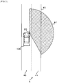
- FIG. 2 is a schematic diagram illustrating the detection region A1 of the external sensor 20.
- the external sensor 20 is, for example, provided at each end in the left and right direction on the front of the own vehicle 100, etc.
- FIG. 2 illustrates the external sensor 20 at the front right end, while the radar at the left end and the radar at other positions also have a detection region, with the same process as the below-mentioned driving support process carried out.
- the own vehicle 100 runs in the left lane 40 of a roadway 4 which has a left lane 40 and a right lane 41 (which are the same lanes in the progress direction).
- a guard rail, a wall of a building, etc., a soundproof wall, etc. are provided along the right lane 41 on a boundary 42 on the right of the roadway 4.
- the detection region A1 of the external sensor 20 spreads like a fan from the right front to the right side and right rear of the own vehicle 100 centering around the external sensor 20. Moreover, the detection region A1 leads to the right of the boundary 42 in the left and right direction, wherein the below-mentioned magnetic waves or ultrasonic waves output by the external sensor 20 are reflected on the guard rail of the boundary 42.
- the external sensor 20 outputs magnetic waves or ultrasonic waves in the detection region A1, in addition to detecting the reflected waves of the output magnetic waves or ultrasonic waves. Based on the value according to the reciprocating time from the external sensor 20 of magnetic waves or ultrasonic waves to the reflection point, a control part 10 measures and detects the position of a detection object such as the vehicle or guard rail in the detection region A1.
- the acceleration sensor 21 detects the acceleration of the own vehicle 100, while the vehicle speed sensor 23 detects the vehicle speed.
- the yaw rate sensor 22 detects the rate (at which the angle (yaw angle) formed between a predetermined direction (for example, the north direction) and the running direction of the own vehicle 100 changes), the so-called yaw rate.
- the values detected by the external sensor 20, the acceleration sensor 21, the yaw rate sensor 22, and the vehicle speed sensor 23 are input into the driving support apparatus 1.
- the notification part 24 is a speaker or LED light, etc. provided in the vehicle interior of the own vehicle 100 and is operated by a signal output by the driving support apparatus 1.
- the communication bus 3 is connected to each ECU equipped with the own vehicle 100 such as a body ECU or engine ECU.
- the driving support apparatus 1 can mutually communicate with each ECU such as the body ECU or engine ECU via the communication bus 3.
- the driving support apparatus 1 and each ECU communicate with each other based on communications standards such as, for example, a CAN (Controller Area Network) and LIN (Local Interconnect Network).
- the driving support apparatus 1 has the control part 10, a storage part 11, an input part 12, a communication part 13, an output part 14, and a communication bus 15.
- the control part 10 is a CPU (Central Processing Unit) or MPU (Micro-Processing Unit), etc.
- the storage part 11 includes a ROM (Read Only Memory), RAM (Random Access Memory), etc., and stores a control program 11a for supporting driving.
- the input part 12 is connected to the external sensor 20, the acceleration sensor 21, the yaw rate sensor 22, and the vehicle speed sensor 23, wherein the values detected by the external sensor 20, the acceleration sensor 21, the yaw rate sensor 22, and the vehicle speed sensor 23 are input into the input part 12.
- the communication part 13 is connected to the communication bus 3.
- the output part 14 is connected to the notification part 24 to output, to the notification part 24, a signal from the control part 10.
- the communication bus 15 is connected to the control part 10, the storage part 11, the input part 12, the communication part 13, and the output part 14, such that the control part 10 can communicate with the storage part 11, the input part 12, the communication part 13, and the output part 14 via the communication bus 15.
- the control part 10 Based on the values input from the external sensor 20, the acceleration sensor 21, the yaw rate sensor 22, and the vehicle speed sensor 23 to the input part 12, as mentioned below, the control part 10 outputs signals to the notification part 24 and the communication bus 3 via the communication part 13 and the output part 14, so as to support driving of the own vehicle 100.
- control part 10 While the own vehicle 100 is running, the control part 10 reads the control program 11a, and periodically carries out the driving support process described below.
- the driving support process will be described with reference to FIGS. 3 to 9 .
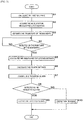
- FIG. 3 is a flowchart illustrating the procedure of the driving support process carried out by the control part 10.
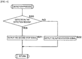
- FIG. 4 is a flowchart illustrating the procedure of the detection process.
- FIG. 5 is a schematic diagram illustrating a false image based on reflection.
- FIGS. 6 and 7 are schematic diagrams illustrating the position of the false image.
- FIG. 8 is a schematic diagram illustrating an estimated progress region.
- FIG. 9 is a schematic diagram illustrating the detection aspect of an object vehicle.
- the control part 10 first acquires a value detected by the external sensor 20 and calculates a first distance D1 (see FIG. 6 ) between the external sensor 20 and the boundary 42 based on this value (S1).
- the first distance D1 refers to the distance serving as the shortest distance such that the straight line extending towards the boundary 42 of a guard rail, wall of a building, soundproof wall, etc. provided along the roadway from the external sensor 20 is orthogonal to this boundary 42.
- the control part 10 acquires the acceleration and vehicle speed of the own vehicle 100 from the acceleration sensor 21 and the vehicle speed sensor 23, in addition to acquiring the yaw rate of the own vehicle 100 from the yaw rate sensor 22 (S2).
- the control part 10 estimates the trajectory of the boundary 42 of the roadway 4 based on the acquired acceleration, vehicle speed, yaw rate, and first distance D1 (S3). At this time, the trajectory of the estimated boundary is parallel in the anteroposterior direction so as to overlap the guard rail of the boundary 42.
- magnetic waves or ultrasonic waves are, for example, reflected on the guard rail on the boundary 42 of the roadway 4 along a reflection path R and lead to the detection object outside the detection region A1.
- an object vehicle 101 which is another vehicle as an object to be detected running in the right lane 41, approaches from behind, magnetic waves or ultrasonic waves reflected on the guard rail are further subjected to multiplexed reflections in the object vehicle 101 and return to the external sensor 20 along the reflection path R. Note that illustrated paths, as well as multiple paths having other angles and distances, are assumed as the reflection path R.
- the control part 10 detects a false image 102 (as a mobile body disposed on the right of the boundary 42) as the object vehicle 101.
- the control part 10 estimates the trajectory of the boundary 42 of the roadway 4, then determines whether or not the detection object has been detected on the right of the boundary 42, based on the value of the external sensor 20 (S4). If the control part 10 determines that the detection object has not been detected (S4: NO), the control part 10 returns the process to Step S4. If the control part 10 determines that the detection object has been detected (S4: YES), a second distance D2 between the false image 102 and the external sensor 20, along with the angle ⁇ formed between the first distance D1 and the second distance D2, is calculated (S5).
- the first distance D1 and the second distance D2 are linear distances.
- the detection object is the false image 102.
- the control part 10 estimates a fifth distance D5 (see FIG. 7 ) between the actual object vehicle 101 and the boundary 42 based on the fourth distance D4, estimates the assumed position P of the actual object vehicle 101, and estimates a progress region A2 of the object vehicle 101 based on this position P (S7). Because multiple reflection paths R of magnetic waves or ultrasonic waves are assumed, the control part 10 assumes multiple fifth distances D5 and positions P.
- the progress region A2 is estimated based on multiple positions P and estimated at a position overlapping the right rear in the detection region A1 at a width including the rightmost position P and the leftmost position P (see FIG. 8 ). Note that in FIG. 8 , an illustration of the object vehicle 101 is omitted.
- the control part 10 estimates the progress region A2, then determines whether or not the detection object has been detected in the progress region A2 (S8). If the control part 10 determines that a detection object has been detected (S8: YES), the control part 10 outputs a first stop signal (S9) and completes the process. If the control part 10 determines that a mobile detection object has not been detected (S8: NO), the control part 10 carries out a detection process (S10).
- the detection object is the object vehicle 101.
- the notification part 24 urges the driver of the own vehicle 100 to refrain from changing lanes due to the output of a sound or flashing of an LED, etc.
- the first stop signal may be output from the control part 10 to another ECU via the communication bus 3, after which the own vehicle 100 may automatically refrain from changing lanes regardless of the operation of the driver.
- the control part 10 determines whether or not a mobile body such as a vehicle has been detected in the detection region A1 in the detection process (S20).
- the control part 10 detects the detection object as a mobile body if reflected waves from the detection object in the detection region A1 are detected four times at times t1, t2, t3, and t4 (t1 ⁇ t2 ⁇ t3 ⁇ t4) (see FIG. 9 ).
- control part 10 determines that a mobile body has been detected (S20: YES)
- the control part 10 outputs a second stop signal (S21) and completes the process. If the control part 10 determines that a mobile body has not been detected (S20: NO), the control part 10 outputs an authentication signal (S22) and completes the process.
- the second stop signal is output from the control part 10 to the notification part 24, after which the driver of the own vehicle 100 is urged to refrain from changing lanes.
- the first stop signal may be output to an ECU connected to the communication bus 3, while the own vehicle 100 may be controlled so as to automatically refrain from changing lanes, regardless of the operation of the driver.
- the authentication signal is output from the control part 10 to the notification part 24, after which the driver of the own vehicle 100 is urged regarding the possibility of changing lanes.
- the authentication signal may be output to the ECU connected to the communication bus 3, after which, regardless of the operation of the driver, the own vehicle 100 may be controlled so as to automatically change lanes.
- the control part 10 if the control part 10 makes a detection on the right of the boundary 42, the control part 10 detects a false image 102 due to the reflection of magnetic waves or ultrasonic waves of the object vehicle 101. Because this false image 102 is detected based on the reflected waves, even when the object vehicle 101 is disposed outside the detection region A1 of the external sensor 20, it can be detected. Therefore, an object vehicle 101 disposed outside the detection region A1 of the external sensor 20 can be detected as a false image 102, while the actual progress region A2 of the object vehicle 101 can be estimated. As a result, before the object vehicle 101 enters the detection region A1, this object vehicle 101 can be detected to estimate the progress region A2. Moreover, it is possible to support, for example, urging the driver to restrain from changing lanes in accordance with the estimated progress region A2, thereby favorably supporting driving.
- the control part 10 characteristically estimates the progress region A2 based on the third distance D3 between the false image 102 and the boundary 42, making it possible to favorably estimate the progress region A2 and support driving.
- the control part 10 estimates the multiple actual positions P of the object vehicle 101 in terms of the false image 102 based on the third distance D3, estimates the progress region A2 of the object vehicle 101 based on the estimated actual positions P, and therefore can estimate the progress region A2 and support driving.
Landscapes
- Engineering & Computer Science (AREA)
- Radar, Positioning & Navigation (AREA)
- Remote Sensing (AREA)
- Physics & Mathematics (AREA)
- General Physics & Mathematics (AREA)
- Automation & Control Theory (AREA)
- Mechanical Engineering (AREA)
- Computer Networks & Wireless Communication (AREA)
- Transportation (AREA)
- Human Computer Interaction (AREA)
- Acoustics & Sound (AREA)
- Electromagnetism (AREA)
- Traffic Control Systems (AREA)
- Radar Systems Or Details Thereof (AREA)
- Measurement Of Velocity Or Position Using Acoustic Or Ultrasonic Waves (AREA)
Abstract
Description
- The present disclosure relates to a driving support apparatus for supporting the driving of a vehicle, etc.
- In terms of safety such as when changing lanes, a vehicle may include a driving support apparatus for supporting the driving of a vehicle by a driver (for example, see Patent Document 1).
- The driving support apparatus outputs magnetic waves or ultrasonic waves to the periphery of a vehicle, in addition to detecting a sensor for detecting a detection object such as another vehicle or a guard rail, based on reflected waves which are detected by a sensor for detecting the reflected waves. The sensor is, for example, a millimeter wave sensor or an ultrasonic wave sensor, etc., and is installed to the front right and left ends of a vehicle, etc. For example, the detection region of the sensor installed at the right end spreads like a fan so as to lead from the right front to the right rear of the vehicle via the right side thereof centering around the sensor.
- If the sensor installed at the right end detects the same detection object in the detection region multiple times, the driving support apparatus detects this detection object as another vehicle approaching from the right rear and estimates the trajectory of the other vehicle as an object to be detected (hereinafter, referred to as an "object vehicle"). If the driving support apparatus detects the object vehicle and estimates the trajectory thereof, for example, a sound, flashing light, etc. urges the driver to refrain from changing lanes.
- Patent Document 1:
JP 2007-531872 W - Unfortunately, the speed of an object vehicle may delay detection and render the estimation of the trajectory of the object vehicle inaccurate.
- The present disclosure has been created in view of the abovementioned problems, with an object of providing a driving support apparatus, driving support method, and computer program, which can favorably support driving.
- A driving support apparatus according to one embodiment of the present disclosure is a driving support apparatus for supporting the driving of a vehicle, including: a boundary estimation part for outputting magnetic waves or ultrasonic waves to the periphery of a vehicle, and for estimating the boundary of a roadway based on reflected waves which are detected by a sensor for detecting the reflected waves; a detection part for detecting a mobile body based on the reflected waves which are detected by the sensor; and a region estimation part for estimating a progress region of the object vehicle which is moving in an adjacent lane when this detection part detects the mobile body generated by multiplexed reflections from an object vehicle which is actually moving in the adjacent lane.
- According to one embodiment of the present disclosure, if the detection part detects a mobile body on the opposite side of the vehicle on the boundary behind the boundary of the roadway, the detection part detects a false image due to the reflection of magnetic waves or ultrasonic waves of the object vehicle which is moving in an adjacent lane. Because this false image is detected based on the reflected waves, the vehicle disposed outside the detection region of the sensor is detected. Therefore, an object vehicle disposed outside the detection region of the sensor can be detected as a false image, while the actual progress region of the object vehicle can be estimated. As a result, before the object vehicle enters the detection region, this object vehicle can be detected to estimate the progress region. Moreover, it is possible to support, for example, urging of the driver to refrain from changing lanes in accordance with the estimated progress region, thereby favorably supporting driving.
- In the driving support apparatus according to one embodiment of the present disclosure, the detection part outputs a stop signal for refraining from changing lanes upon detecting the mobile body disposed in the progress region.
- According to one embodiment of the present disclosure, when the object vehicle enters the estimated progress region, refraining from changing lanes can be urged or restraint executed. Therefore, before the object vehicle enters the detection region of the sensor and is detected, it is possible to detect the object vehicle, urge to refrain from changing lanes, or execute restraint, making it possible to favorably support driving.
- In the driving support apparatus according to one embodiment of the present disclosure, the region estimation part estimates the progress region of the object vehicle in the adjacent lane, based on the distance between the boundary and the mobile body which the detection part has detected behind the boundary of the roadway.
- According to one embodiment of the present disclosure, the progress region can be favorably estimated to support driving.
- In the driving support apparatus according to one embodiment of the present disclosure, the region estimation part estimates the actual position of the object vehicle, based on the mobile body due to the multiplexed reflections from behind the boundary of the roadway.
- According to one embodiment of the present disclosure, the progress region can be favorably estimated to support driving.
- A driving support method according to one embodiment of the present disclosure is a driving support method for supporting the driving of a vehicle, including the steps of: outputting magnetic waves or ultrasonic waves to a periphery of a vehicle, and estimating a boundary of a roadway based on reflected waves which are detected by a sensor for detecting the reflected waves; detecting a mobile body based on multiplexed reflected waves which are detected by the sensor; and estimating a progress region of the object vehicle (when the object vehicle is disposed on the vehicle side of the boundary), based on a position of the detected object vehicle, upon detecting an object vehicle which is moving in an adjacent lane behind the boundary of the roadway.
- According to one embodiment of the present disclosure, an object vehicle disposed outside the detection region of the sensor can be detected as a false image, while the actual progress region of the object vehicle can be estimated. As a result, before the object vehicle enters the detection region, this object vehicle can be detected to estimate the progress region. Moreover, it is possible to support, for example, urging the driver to refrain from changing lanes in accordance with the estimated progress region, thereby favorably supporting driving.
- A computer program according to one embodiment of the present disclosure is a computer program for making a computer execute the processes of: outputting magnetic waves or ultrasonic waves to a periphery of a vehicle, and estimating a boundary of a roadway based on reflected waves which are detected by a sensor for detecting the reflected waves; detecting a mobile body based on multiplexed reflected waves which are detected by the sensor; and estimating a progress region of the object vehicle (when the object vehicle is disposed on the vehicle side of the boundary) based on a position of the detected object vehicle upon detecting an object vehicle which is moving in an adjacent lane behind the boundary of the roadway.
- According to one embodiment of the present disclosure, an object vehicle disposed outside the detection region of the sensor can be detected as a false image, while the actual progress region of the object vehicle can be estimated. As a result, before the object vehicle enters the detection region, this object vehicle can be detected to estimate the progress region. Moreover, it is possible to support, for example, urging the driver to refrain from changing lanes in accordance with the estimated progress region, thereby favorably supporting driving.
- According to one embodiment of the present disclosure, driving can be favorably supported.
-
-
FIG. 1 is a block diagram illustrating the configuration of a vehicle equipped with a driving support apparatus according to an embodiment. -
FIG. 2 is a schematic diagram illustrating a detection region of an external sensor. -
FIG. 3 is a flowchart illustrating a procedure of a driving support process carried out by a control part. -
FIG. 4 is a flowchart illustrating the procedure of the detection process. -
FIG. 5 is a schematic diagram illustrating a false image based on reflection. -
FIG. 6 is a schematic diagram illustrating the position of the false image. -
FIG. 7 is a schematic diagram illustrating the position of the false image. -
FIG. 8 is a schematic diagram illustrating an estimated progress region. -
FIG. 9 is a schematic diagram illustrating the detection aspect of an object vehicle. - Hereinafter, a driving support apparatus according to the present disclosure will be described in detail based on the drawings indicating the embodiments.
-
FIG. 1 is a block diagram illustrating the configuration of a vehicle equipped with a driving support apparatus according to an embodiment. InFIG. 1 , 100 illustrated is an own vehicle, wherein theown vehicle 100 includes adriving support apparatus 1, anexternal sensor 20, anacceleration sensor 21, ayaw rate sensor 22, avehicle speed sensor 23, anotification part 24, and acommunication bus 3. Hereinafter, the left and right of theown vehicle 100 respectively refer to the left hand direction and the right hand direction with respect to the common progress direction of the vehicle. Theown vehicle 100 runs via manual driving by a passenger or via automatic driving under the control of an ECU (Electronic Control Unit). - The
driving support apparatus 1 is connected to theexternal sensor 20, theacceleration sensor 21, theyaw rate sensor 22, thevehicle speed sensor 23, thenotification part 24, and thecommunication bus 3. Theexternal sensor 20 is a millimeter wave radar, ultrasonic wave sensor, etc., and outputs magnetic waves or ultrasonic waves to the periphery of the vehicle, in addition to detecting the reflected waves of the output magnetic waves or ultrasonic waves. -
FIG. 2 is a schematic diagram illustrating the detection region A1 of theexternal sensor 20. Theexternal sensor 20 is, for example, provided at each end in the left and right direction on the front of theown vehicle 100, etc.FIG. 2 illustrates theexternal sensor 20 at the front right end, while the radar at the left end and the radar at other positions also have a detection region, with the same process as the below-mentioned driving support process carried out. InFIG. 2 , theown vehicle 100 runs in theleft lane 40 of aroadway 4 which has aleft lane 40 and a right lane 41 (which are the same lanes in the progress direction). A guard rail, a wall of a building, etc., a soundproof wall, etc. are provided along theright lane 41 on aboundary 42 on the right of theroadway 4. - As illustrated in
FIG. 2 , the detection region A1 of theexternal sensor 20 spreads like a fan from the right front to the right side and right rear of theown vehicle 100 centering around theexternal sensor 20. Moreover, the detection region A1 leads to the right of theboundary 42 in the left and right direction, wherein the below-mentioned magnetic waves or ultrasonic waves output by theexternal sensor 20 are reflected on the guard rail of theboundary 42. - The
external sensor 20 outputs magnetic waves or ultrasonic waves in the detection region A1, in addition to detecting the reflected waves of the output magnetic waves or ultrasonic waves. Based on the value according to the reciprocating time from theexternal sensor 20 of magnetic waves or ultrasonic waves to the reflection point, acontrol part 10 measures and detects the position of a detection object such as the vehicle or guard rail in the detection region A1. - The
acceleration sensor 21 detects the acceleration of theown vehicle 100, while thevehicle speed sensor 23 detects the vehicle speed. Theyaw rate sensor 22 detects the rate (at which the angle (yaw angle) formed between a predetermined direction (for example, the north direction) and the running direction of theown vehicle 100 changes), the so-called yaw rate. The values detected by theexternal sensor 20, theacceleration sensor 21, theyaw rate sensor 22, and thevehicle speed sensor 23 are input into the drivingsupport apparatus 1. - The
notification part 24 is a speaker or LED light, etc. provided in the vehicle interior of theown vehicle 100 and is operated by a signal output by the drivingsupport apparatus 1. Thecommunication bus 3 is connected to each ECU equipped with theown vehicle 100 such as a body ECU or engine ECU. The drivingsupport apparatus 1 can mutually communicate with each ECU such as the body ECU or engine ECU via thecommunication bus 3. The drivingsupport apparatus 1 and each ECU communicate with each other based on communications standards such as, for example, a CAN (Controller Area Network) and LIN (Local Interconnect Network). - The driving
support apparatus 1 has thecontrol part 10, astorage part 11, aninput part 12, acommunication part 13, anoutput part 14, and acommunication bus 15. Thecontrol part 10 is a CPU (Central Processing Unit) or MPU (Micro-Processing Unit), etc. Thestorage part 11 includes a ROM (Read Only Memory), RAM (Random Access Memory), etc., and stores acontrol program 11a for supporting driving. Theinput part 12 is connected to theexternal sensor 20, theacceleration sensor 21, theyaw rate sensor 22, and thevehicle speed sensor 23, wherein the values detected by theexternal sensor 20, theacceleration sensor 21, theyaw rate sensor 22, and thevehicle speed sensor 23 are input into theinput part 12. - The
communication part 13 is connected to thecommunication bus 3. Theoutput part 14 is connected to thenotification part 24 to output, to thenotification part 24, a signal from thecontrol part 10. Thecommunication bus 15 is connected to thecontrol part 10, thestorage part 11, theinput part 12, thecommunication part 13, and theoutput part 14, such that thecontrol part 10 can communicate with thestorage part 11, theinput part 12, thecommunication part 13, and theoutput part 14 via thecommunication bus 15. - In the driving
support apparatus 1, based on the values input from theexternal sensor 20, theacceleration sensor 21, theyaw rate sensor 22, and thevehicle speed sensor 23 to theinput part 12, as mentioned below, thecontrol part 10 outputs signals to thenotification part 24 and thecommunication bus 3 via thecommunication part 13 and theoutput part 14, so as to support driving of theown vehicle 100. - While the
own vehicle 100 is running, thecontrol part 10 reads thecontrol program 11a, and periodically carries out the driving support process described below. The driving support process will be described with reference toFIGS. 3 to 9 . -
FIG. 3 is a flowchart illustrating the procedure of the driving support process carried out by thecontrol part 10.FIG. 4 is a flowchart illustrating the procedure of the detection process.FIG. 5 is a schematic diagram illustrating a false image based on reflection.FIGS. 6 and7 are schematic diagrams illustrating the position of the false image.FIG. 8 is a schematic diagram illustrating an estimated progress region.FIG. 9 is a schematic diagram illustrating the detection aspect of an object vehicle. - The
control part 10 first acquires a value detected by theexternal sensor 20 and calculates a first distance D1 (seeFIG. 6 ) between theexternal sensor 20 and theboundary 42 based on this value (S1). The first distance D1 refers to the distance serving as the shortest distance such that the straight line extending towards theboundary 42 of a guard rail, wall of a building, soundproof wall, etc. provided along the roadway from theexternal sensor 20 is orthogonal to thisboundary 42. Subsequently, thecontrol part 10 acquires the acceleration and vehicle speed of theown vehicle 100 from theacceleration sensor 21 and thevehicle speed sensor 23, in addition to acquiring the yaw rate of theown vehicle 100 from the yaw rate sensor 22 (S2). - The
control part 10 estimates the trajectory of theboundary 42 of theroadway 4 based on the acquired acceleration, vehicle speed, yaw rate, and first distance D1 (S3). At this time, the trajectory of the estimated boundary is parallel in the anteroposterior direction so as to overlap the guard rail of theboundary 42. - Here, as illustrated in
FIG. 5 , also outside the detection region A1 of theexternal sensor 20, magnetic waves or ultrasonic waves are, for example, reflected on the guard rail on theboundary 42 of theroadway 4 along a reflection path R and lead to the detection object outside the detection region A1. If anobject vehicle 101, which is another vehicle as an object to be detected running in theright lane 41, approaches from behind, magnetic waves or ultrasonic waves reflected on the guard rail are further subjected to multiplexed reflections in theobject vehicle 101 and return to theexternal sensor 20 along the reflection path R. Note that illustrated paths, as well as multiple paths having other angles and distances, are assumed as the reflection path R. - If the
external sensor 20 detects reflected waves due to the so-called multiplexed reflections along the reflection path R as mentioned above, thecontrol part 10 detects a false image 102 (as a mobile body disposed on the right of the boundary 42) as theobject vehicle 101. - The
control part 10 estimates the trajectory of theboundary 42 of theroadway 4, then determines whether or not the detection object has been detected on the right of theboundary 42, based on the value of the external sensor 20 (S4). If thecontrol part 10 determines that the detection object has not been detected (S4: NO), thecontrol part 10 returns the process to Step S4. If thecontrol part 10 determines that the detection object has been detected (S4: YES), a second distance D2 between thefalse image 102 and theexternal sensor 20, along with the angle θ formed between the first distance D1 and the second distance D2, is calculated (S5). Here, the first distance D1 and the second distance D2 are linear distances. Moreover, the detection object is thefalse image 102. - Subsequently, the
control part 10 calculates a third distance D3 (D3=D1/cosθ=D1×secθ, seeFIG. 7 ) between theexternal sensor 20 and theboundary 42 in the second distance D2, subtracts the third distance D3 from the second distance D2, and calculates a fourth distance D4 (D4=D2-D3=the distance between thefalse image 102 and the external sensor 20-D1×secθ, seeFIG. 7 ) between thefalse image 102 and the boundary 42 (S6). - Subsequently, the
control part 10 estimates a fifth distance D5 (seeFIG. 7 ) between theactual object vehicle 101 and theboundary 42 based on the fourth distance D4, estimates the assumed position P of theactual object vehicle 101, and estimates a progress region A2 of theobject vehicle 101 based on this position P (S7). Because multiple reflection paths R of magnetic waves or ultrasonic waves are assumed, thecontrol part 10 assumes multiple fifth distances D5 and positions P. The progress region A2 is estimated based on multiple positions P and estimated at a position overlapping the right rear in the detection region A1 at a width including the rightmost position P and the leftmost position P (seeFIG. 8 ). Note that inFIG. 8 , an illustration of theobject vehicle 101 is omitted. - The
control part 10 estimates the progress region A2, then determines whether or not the detection object has been detected in the progress region A2 (S8). If thecontrol part 10 determines that a detection object has been detected (S8: YES), thecontrol part 10 outputs a first stop signal (S9) and completes the process. If thecontrol part 10 determines that a mobile detection object has not been detected (S8: NO), thecontrol part 10 carries out a detection process (S10). Here, the detection object is theobject vehicle 101. - If the first stop signal is, for example, output from the
control part 10 to thenotification part 24 and the first stop signal is input, thenotification part 24 urges the driver of theown vehicle 100 to refrain from changing lanes due to the output of a sound or flashing of an LED, etc. Moreover, the first stop signal may be output from thecontrol part 10 to another ECU via thecommunication bus 3, after which theown vehicle 100 may automatically refrain from changing lanes regardless of the operation of the driver. - The
control part 10 determines whether or not a mobile body such as a vehicle has been detected in the detection region A1 in the detection process (S20). Here, upon detecting the mobile body, thecontrol part 10 detects the detection object as a mobile body if reflected waves from the detection object in the detection region A1 are detected four times at times t1, t2, t3, and t4 (t1<t2<t3<t4) (seeFIG. 9 ). - If the
control part 10 determines that a mobile body has been detected (S20: YES), thecontrol part 10 outputs a second stop signal (S21) and completes the process. If thecontrol part 10 determines that a mobile body has not been detected (S20: NO), thecontrol part 10 outputs an authentication signal (S22) and completes the process. - The second stop signal is output from the
control part 10 to thenotification part 24, after which the driver of theown vehicle 100 is urged to refrain from changing lanes. Moreover, the first stop signal may be output to an ECU connected to thecommunication bus 3, while theown vehicle 100 may be controlled so as to automatically refrain from changing lanes, regardless of the operation of the driver. The authentication signal is output from thecontrol part 10 to thenotification part 24, after which the driver of theown vehicle 100 is urged regarding the possibility of changing lanes. Moreover, the authentication signal may be output to the ECU connected to thecommunication bus 3, after which, regardless of the operation of the driver, theown vehicle 100 may be controlled so as to automatically change lanes. - According to the above configuration, if the
control part 10 makes a detection on the right of theboundary 42, thecontrol part 10 detects afalse image 102 due to the reflection of magnetic waves or ultrasonic waves of theobject vehicle 101. Because thisfalse image 102 is detected based on the reflected waves, even when theobject vehicle 101 is disposed outside the detection region A1 of theexternal sensor 20, it can be detected. Therefore, anobject vehicle 101 disposed outside the detection region A1 of theexternal sensor 20 can be detected as afalse image 102, while the actual progress region A2 of theobject vehicle 101 can be estimated. As a result, before theobject vehicle 101 enters the detection region A1, thisobject vehicle 101 can be detected to estimate the progress region A2. Moreover, it is possible to support, for example, urging the driver to restrain from changing lanes in accordance with the estimated progress region A2, thereby favorably supporting driving. - When the
object vehicle 101 enters the estimated progress region A2, refraining from changing lanes can be urged or restraint can be executed. Therefore, before theobject vehicle 101 enters the detection region A1 of theexternal sensor 20 to make a detection, it is possible to detect theobject vehicle 101, urge to refrain from changing lanes, or execute restraint, making it possible to favorably support driving. - The
control part 10 characteristically estimates the progress region A2 based on the third distance D3 between thefalse image 102 and theboundary 42, making it possible to favorably estimate the progress region A2 and support driving. Thecontrol part 10 estimates the multiple actual positions P of theobject vehicle 101 in terms of thefalse image 102 based on the third distance D3, estimates the progress region A2 of theobject vehicle 101 based on the estimated actual positions P, and therefore can estimate the progress region A2 and support driving. - Embodiments not disclosed herein should be regarded as illustrative in all respects and not restrictive. The scope of the present disclosure is indicated not by the abovementioned meaning but by the claims and is intended to include all changes in the meaning and scope equivalent to the claims. That is, embodiments obtained by combining the technical means which is appropriately changed within the scope indicated in the claims are included in the technical scope of the present disclosure.
-
- 1 Driving support apparatus
- 10 Control part (boundary estimation part, detection part, and region estimation part)
- 11a Control program
- 20 External sensor (sensor)
- 42 Boundary
- 100 Own vehicle (vehicle)
- 101 Object vehicle
- 102 False image
- A1 Detection region
- A2 Progress region
- D3 Third distance (distance)
- P Actual position
Claims (6)
- A driving support apparatus for supporting the driving of a vehicle, comprising:a boundary estimation part for outputting magnetic waves or ultrasonic waves to the periphery of a vehicle, and for estimating the boundary of a roadway based on reflected waves which are detected by a sensor for detecting the reflected waves;a detection part for detecting a mobile body based on the reflected waves which are detected by the sensor; anda region estimation part for estimating a progress region of the object vehicle which is moving in an adjacent lane when this detection part detects the mobile body generated by multiplexed reflections from an object vehicle which is actually moving in the adjacent lane.
- The driving support apparatus according to claim 1, wherein the detection part outputs a stop signal for refraining from changing lanes upon detecting the mobile body disposed in the progress region.
- The driving support apparatus according to claim 1 or 2, wherein the region estimation part estimates the progress region of the object vehicle in the adjacent lane, based on the distance between the boundary and the mobile body which the detection part has detected behind the boundary of the roadway.
- The driving support apparatus according to claim 3, wherein the region estimation part estimates the actual position of the object vehicle, based on the mobile body due to the multiplexed reflections from behind the boundary of the roadway.
- A driving support method for supporting the driving of a vehicle, comprising the steps of:outputting magnetic waves or ultrasonic waves to the periphery of a vehicle, and estimating the boundary of a roadway based on reflected waves which are detected by a sensor for detecting the reflected waves;detecting a mobile body based on the multiplexed reflected waves which are detected by the sensor; andestimating a progress region of the object vehicle (when the object vehicle is disposed on the vehicle side of the boundary), based on a position of the detected object vehicle, upon detecting an object vehicle which is moving in an adjacent lane behind the boundary of the roadway.
- A computer program for making a computer execute the processes of:outputting magnetic waves or ultrasonic waves to the periphery of a vehicle, and estimating the boundary of a roadway based on reflected waves which are detected by a sensor for detecting the reflected waves;detecting a mobile body based on the multiplexed reflected waves which are detected by the sensor; andestimating a progress region of the object vehicle (when the object vehicle is disposed on the vehicle side of the boundary) based on a position of the detected object vehicle upon detecting an object vehicle which is moving in an adjacent lane behind the boundary of the roadway.
Applications Claiming Priority (2)
| Application Number | Priority Date | Filing Date | Title |
|---|---|---|---|
| JP2017117667 | 2017-06-15 | ||
| PCT/JP2018/020693 WO2018230344A1 (en) | 2017-06-15 | 2018-05-30 | Driving assistance device, driving assistance method, and computer program |
Publications (2)
| Publication Number | Publication Date |
|---|---|
| EP3640919A1 true EP3640919A1 (en) | 2020-04-22 |
| EP3640919A4 EP3640919A4 (en) | 2021-01-27 |
Family
ID=64659730
Family Applications (1)
| Application Number | Title | Priority Date | Filing Date |
|---|---|---|---|
| EP18816892.6A Withdrawn EP3640919A4 (en) | 2017-06-15 | 2018-05-30 | DRIVING ASSISTANCE DEVICE, DRIVING ASSISTANCE PROCESS AND COMPUTER PROGRAM |
Country Status (4)
| Country | Link |
|---|---|
| US (1) | US11332135B2 (en) |
| EP (1) | EP3640919A4 (en) |
| JP (1) | JP7030117B2 (en) |
| WO (1) | WO2018230344A1 (en) |
Families Citing this family (5)
| Publication number | Priority date | Publication date | Assignee | Title |
|---|---|---|---|---|
| JP7169873B2 (en) * | 2018-12-27 | 2022-11-11 | 株式会社デンソー | Driving support device |
| JP7366695B2 (en) * | 2019-11-06 | 2023-10-23 | 日産自動車株式会社 | Object recognition method and object recognition device |
| BE1028219B1 (en) * | 2020-04-20 | 2021-11-24 | Rombit Nv | METHOD, SYSTEM AND COMPUTER PROGRAM PRODUCT FOR BLIND STAIN DETECTION |
| JP2023536150A (en) * | 2020-07-29 | 2023-08-23 | ニューラル プロパルション システムズ,インコーポレイテッド | Multi-frequency radar array system and sensor fusion for viewing around corners during autonomous driving |
| JP2025094609A (en) * | 2023-12-13 | 2025-06-25 | 本田技研工業株式会社 | MOBILE BODY CONTROL DEVICE, MOBILE BODY CONTROL METHOD, AND PROGRAM |
Family Cites Families (16)
| Publication number | Priority date | Publication date | Assignee | Title |
|---|---|---|---|---|
| JPH09132094A (en) * | 1995-11-09 | 1997-05-20 | Nissan Motor Co Ltd | Lane change notification device |
| JP2000147115A (en) * | 1998-11-04 | 2000-05-26 | Toyota Motor Corp | Automotive radar equipment |
| JP3608991B2 (en) | 1999-10-22 | 2005-01-12 | 富士通テン株式会社 | Inter-vehicle distance sensor |
| JP3770189B2 (en) | 2002-03-19 | 2006-04-26 | 株式会社デンソー | Object recognition device, object recognition method, radar device |
| DE102004004492A1 (en) * | 2004-01-29 | 2005-08-18 | Robert Bosch Gmbh | Radar system for motor vehicles |
| DE102004036580A1 (en) * | 2004-07-28 | 2006-03-16 | Robert Bosch Gmbh | Method and device for object detection in a vehicle |
| JP5075656B2 (en) * | 2008-02-05 | 2012-11-21 | 本田技研工業株式会社 | Object detection device |
| DE102012105582A1 (en) * | 2011-07-01 | 2013-01-03 | Conti Temic Microelectronic Gmbh | Simplified calculation of high-resolution angle estimation of two targets with radar system for motor vehicles |
| JP6077226B2 (en) * | 2012-05-31 | 2017-02-08 | 富士通テン株式会社 | Radar apparatus and signal processing method |
| US8473144B1 (en) * | 2012-10-30 | 2013-06-25 | Google Inc. | Controlling vehicle lateral lane positioning |
| JP6063319B2 (en) | 2013-03-27 | 2017-01-18 | 富士重工業株式会社 | Lane change support device |
| DE102014201026A1 (en) * | 2014-01-21 | 2015-07-23 | Robert Bosch Gmbh | Method for angle estimation and radar sensor for motor vehicles |
| JP2015230566A (en) * | 2014-06-04 | 2015-12-21 | トヨタ自動車株式会社 | Driving support device |
| JP2016148547A (en) | 2015-02-10 | 2016-08-18 | トヨタ自動車株式会社 | Detection device |
| JP6668895B2 (en) * | 2016-04-01 | 2020-03-18 | 株式会社デンソー | Driving support device |
| US10290214B2 (en) * | 2017-04-11 | 2019-05-14 | Denso International America, Inc. | Lane change system and lane change controller |
-
2018
- 2018-05-30 US US16/615,262 patent/US11332135B2/en active Active
- 2018-05-30 EP EP18816892.6A patent/EP3640919A4/en not_active Withdrawn
- 2018-05-30 JP JP2019525295A patent/JP7030117B2/en active Active
- 2018-05-30 WO PCT/JP2018/020693 patent/WO2018230344A1/en not_active Ceased
Also Published As
| Publication number | Publication date |
|---|---|
| EP3640919A4 (en) | 2021-01-27 |
| US20200086867A1 (en) | 2020-03-19 |
| JPWO2018230344A1 (en) | 2020-03-26 |
| WO2018230344A1 (en) | 2018-12-20 |
| JP7030117B2 (en) | 2022-03-04 |
| US11332135B2 (en) | 2022-05-17 |
Similar Documents
| Publication | Publication Date | Title |
|---|---|---|
| US11332135B2 (en) | Driving assistance device, driving assistance method, and computer program | |
| JP6152673B2 (en) | Lane change support device | |
| JP4396400B2 (en) | Obstacle recognition device | |
| US8862383B2 (en) | Apparatus for judging probability of collision between vehicle and object surrounding the vehicle | |
| JP6327708B2 (en) | Vehicle driving support device | |
| JP4788778B2 (en) | Deviation warning device and deviation warning program | |
| JP5846034B2 (en) | Boundary line detection device, deviation detection device, and boundary line detection program | |
| KR102112125B1 (en) | Vehicle control device | |
| KR101843073B1 (en) | Driving assistance device for vehicles and onboard computer | |
| US20140297170A1 (en) | Driving support system | |
| JP6412346B2 (en) | Vehicle driving support device | |
| KR20140128236A (en) | Vehicle-use collision mitigation apparatus | |
| CN107408347B (en) | Object detection device and object detection method | |
| US10800432B2 (en) | Rear-side alert system and method of controlling same | |
| WO2017111147A1 (en) | Travel assistance device and travel assistance method | |
| CN104276121A (en) | Vehicle system for control of vehicle safety parameters, vehicle and method for controlling safety parameters | |
| US20140297134A1 (en) | On-board apparatus | |
| CN106575479A (en) | Driving assistance apparatus | |
| WO2019012995A1 (en) | Driving support device | |
| JP2014119285A (en) | Object detection apparatus | |
| JP7344077B2 (en) | Collision determination device | |
| US12559091B2 (en) | Control device for controlling safety device in vehicle | |
| JP4872517B2 (en) | Obstacle recognition device | |
| JP6934432B2 (en) | Target detection device, target detection method and program | |
| WO2017154471A1 (en) | Crossing determination device |
Legal Events
| Date | Code | Title | Description |
|---|---|---|---|
| STAA | Information on the status of an ep patent application or granted ep patent |
Free format text: STATUS: THE INTERNATIONAL PUBLICATION HAS BEEN MADE |
|
| PUAI | Public reference made under article 153(3) epc to a published international application that has entered the european phase |
Free format text: ORIGINAL CODE: 0009012 |
|
| STAA | Information on the status of an ep patent application or granted ep patent |
Free format text: STATUS: REQUEST FOR EXAMINATION WAS MADE |
|
| 17P | Request for examination filed |
Effective date: 20200109 |
|
| AK | Designated contracting states |
Kind code of ref document: A1 Designated state(s): AL AT BE BG CH CY CZ DE DK EE ES FI FR GB GR HR HU IE IS IT LI LT LU LV MC MK MT NL NO PL PT RO RS SE SI SK SM TR |
|
| AX | Request for extension of the european patent |
Extension state: BA ME |
|
| DAV | Request for validation of the european patent (deleted) | ||
| DAX | Request for extension of the european patent (deleted) | ||
| A4 | Supplementary search report drawn up and despatched |
Effective date: 20210114 |
|
| RIC1 | Information provided on ipc code assigned before grant |
Ipc: G08G 1/16 20060101AFI20201223BHEP Ipc: B60R 21/00 20060101ALI20201223BHEP Ipc: B60W 30/08 20120101ALI20201223BHEP Ipc: G01S 7/527 20060101ALN20201223BHEP Ipc: G01S 7/41 20060101ALI20201223BHEP Ipc: G01S 13/931 20200101ALI20201223BHEP Ipc: G01S 7/35 20060101ALN20201223BHEP Ipc: B60W 30/095 20120101ALI20201223BHEP Ipc: G01S 15/42 20060101ALI20201223BHEP Ipc: G01S 15/931 20200101ALI20201223BHEP Ipc: G01S 13/93 20200101ALI20201223BHEP Ipc: B60W 50/14 20200101ALI20201223BHEP Ipc: B60W 60/00 20200101ALI20201223BHEP Ipc: G01S 7/539 20060101ALI20201223BHEP Ipc: G01S 13/86 20060101ALN20201223BHEP Ipc: G01S 13/42 20060101ALI20201223BHEP Ipc: G01S 7/292 20060101ALN20201223BHEP |
|
| STAA | Information on the status of an ep patent application or granted ep patent |
Free format text: STATUS: EXAMINATION IS IN PROGRESS |
|
| 17Q | First examination report despatched |
Effective date: 20230609 |
|
| STAA | Information on the status of an ep patent application or granted ep patent |
Free format text: STATUS: THE APPLICATION IS DEEMED TO BE WITHDRAWN |
|
| 18D | Application deemed to be withdrawn |
Effective date: 20231020 |