EP3640670B1 - Multiple-pulses-in-air laser scanning system with ambiguity resolution based on range probing and 3d point analysis - Google Patents
Multiple-pulses-in-air laser scanning system with ambiguity resolution based on range probing and 3d point analysis Download PDFInfo
- Publication number
- EP3640670B1 EP3640670B1 EP19201944.6A EP19201944A EP3640670B1 EP 3640670 B1 EP3640670 B1 EP 3640670B1 EP 19201944 A EP19201944 A EP 19201944A EP 3640670 B1 EP3640670 B1 EP 3640670B1
- Authority
- EP
- European Patent Office
- Prior art keywords
- pulses
- pulse
- send
- return
- laser scanner
- Prior art date
- Legal status (The legal status is an assumption and is not a legal conclusion. Google has not performed a legal analysis and makes no representation as to the accuracy of the status listed.)
- Active
Links
Images




Classifications
-
- G—PHYSICS
- G01—MEASURING; TESTING
- G01S—RADIO DIRECTION-FINDING; RADIO NAVIGATION; DETERMINING DISTANCE OR VELOCITY BY USE OF RADIO WAVES; LOCATING OR PRESENCE-DETECTING BY USE OF THE REFLECTION OR RERADIATION OF RADIO WAVES; ANALOGOUS ARRANGEMENTS USING OTHER WAVES
- G01S17/00—Systems using the reflection or reradiation of electromagnetic waves other than radio waves, e.g. lidar systems
- G01S17/02—Systems using the reflection of electromagnetic waves other than radio waves
- G01S17/06—Systems determining position data of a target
- G01S17/08—Systems determining position data of a target for measuring distance only
-
- G—PHYSICS
- G01—MEASURING; TESTING
- G01S—RADIO DIRECTION-FINDING; RADIO NAVIGATION; DETERMINING DISTANCE OR VELOCITY BY USE OF RADIO WAVES; LOCATING OR PRESENCE-DETECTING BY USE OF THE REFLECTION OR RERADIATION OF RADIO WAVES; ANALOGOUS ARRANGEMENTS USING OTHER WAVES
- G01S7/00—Details of systems according to groups G01S13/00, G01S15/00, G01S17/00
- G01S7/48—Details of systems according to groups G01S13/00, G01S15/00, G01S17/00 of systems according to group G01S17/00
- G01S7/483—Details of pulse systems
- G01S7/486—Receivers
- G01S7/4861—Circuits for detection, sampling, integration or read-out
-
- G—PHYSICS
- G01—MEASURING; TESTING
- G01C—MEASURING DISTANCES, LEVELS OR BEARINGS; SURVEYING; NAVIGATION; GYROSCOPIC INSTRUMENTS; PHOTOGRAMMETRY OR VIDEOGRAMMETRY
- G01C15/00—Surveying instruments or accessories not provided for in groups G01C1/00 - G01C13/00
- G01C15/002—Active optical surveying means
-
- G—PHYSICS
- G01—MEASURING; TESTING
- G01S—RADIO DIRECTION-FINDING; RADIO NAVIGATION; DETERMINING DISTANCE OR VELOCITY BY USE OF RADIO WAVES; LOCATING OR PRESENCE-DETECTING BY USE OF THE REFLECTION OR RERADIATION OF RADIO WAVES; ANALOGOUS ARRANGEMENTS USING OTHER WAVES
- G01S17/00—Systems using the reflection or reradiation of electromagnetic waves other than radio waves, e.g. lidar systems
- G01S17/02—Systems using the reflection of electromagnetic waves other than radio waves
- G01S17/06—Systems determining position data of a target
- G01S17/08—Systems determining position data of a target for measuring distance only
- G01S17/10—Systems determining position data of a target for measuring distance only using transmission of interrupted, pulse-modulated waves
-
- G—PHYSICS
- G01—MEASURING; TESTING
- G01S—RADIO DIRECTION-FINDING; RADIO NAVIGATION; DETERMINING DISTANCE OR VELOCITY BY USE OF RADIO WAVES; LOCATING OR PRESENCE-DETECTING BY USE OF THE REFLECTION OR RERADIATION OF RADIO WAVES; ANALOGOUS ARRANGEMENTS USING OTHER WAVES
- G01S17/00—Systems using the reflection or reradiation of electromagnetic waves other than radio waves, e.g. lidar systems
- G01S17/02—Systems using the reflection of electromagnetic waves other than radio waves
- G01S17/06—Systems determining position data of a target
- G01S17/42—Simultaneous measurement of distance and other co-ordinates
-
- G—PHYSICS
- G01—MEASURING; TESTING
- G01S—RADIO DIRECTION-FINDING; RADIO NAVIGATION; DETERMINING DISTANCE OR VELOCITY BY USE OF RADIO WAVES; LOCATING OR PRESENCE-DETECTING BY USE OF THE REFLECTION OR RERADIATION OF RADIO WAVES; ANALOGOUS ARRANGEMENTS USING OTHER WAVES
- G01S17/00—Systems using the reflection or reradiation of electromagnetic waves other than radio waves, e.g. lidar systems
- G01S17/88—Lidar systems specially adapted for specific applications
-
- G—PHYSICS
- G01—MEASURING; TESTING
- G01S—RADIO DIRECTION-FINDING; RADIO NAVIGATION; DETERMINING DISTANCE OR VELOCITY BY USE OF RADIO WAVES; LOCATING OR PRESENCE-DETECTING BY USE OF THE REFLECTION OR RERADIATION OF RADIO WAVES; ANALOGOUS ARRANGEMENTS USING OTHER WAVES
- G01S17/00—Systems using the reflection or reradiation of electromagnetic waves other than radio waves, e.g. lidar systems
- G01S17/88—Lidar systems specially adapted for specific applications
- G01S17/89—Lidar systems specially adapted for specific applications for mapping or imaging
-
- G—PHYSICS
- G01—MEASURING; TESTING
- G01S—RADIO DIRECTION-FINDING; RADIO NAVIGATION; DETERMINING DISTANCE OR VELOCITY BY USE OF RADIO WAVES; LOCATING OR PRESENCE-DETECTING BY USE OF THE REFLECTION OR RERADIATION OF RADIO WAVES; ANALOGOUS ARRANGEMENTS USING OTHER WAVES
- G01S7/00—Details of systems according to groups G01S13/00, G01S15/00, G01S17/00
- G01S7/48—Details of systems according to groups G01S13/00, G01S15/00, G01S17/00 of systems according to group G01S17/00
- G01S7/4808—Evaluating distance, position or velocity data
-
- G—PHYSICS
- G01—MEASURING; TESTING
- G01S—RADIO DIRECTION-FINDING; RADIO NAVIGATION; DETERMINING DISTANCE OR VELOCITY BY USE OF RADIO WAVES; LOCATING OR PRESENCE-DETECTING BY USE OF THE REFLECTION OR RERADIATION OF RADIO WAVES; ANALOGOUS ARRANGEMENTS USING OTHER WAVES
- G01S7/00—Details of systems according to groups G01S13/00, G01S15/00, G01S17/00
- G01S7/48—Details of systems according to groups G01S13/00, G01S15/00, G01S17/00 of systems according to group G01S17/00
- G01S7/481—Constructional features, e.g. arrangements of optical elements
- G01S7/4817—Constructional features, e.g. arrangements of optical elements relating to scanning
-
- G—PHYSICS
- G01—MEASURING; TESTING
- G01S—RADIO DIRECTION-FINDING; RADIO NAVIGATION; DETERMINING DISTANCE OR VELOCITY BY USE OF RADIO WAVES; LOCATING OR PRESENCE-DETECTING BY USE OF THE REFLECTION OR RERADIATION OF RADIO WAVES; ANALOGOUS ARRANGEMENTS USING OTHER WAVES
- G01S7/00—Details of systems according to groups G01S13/00, G01S15/00, G01S17/00
- G01S7/48—Details of systems according to groups G01S13/00, G01S15/00, G01S17/00 of systems according to group G01S17/00
- G01S7/483—Details of pulse systems
- G01S7/486—Receivers
- G01S7/4865—Time delay measurement, e.g. time-of-flight measurement, time of arrival measurement or determining the exact position of a peak
-
- G—PHYSICS
- G01—MEASURING; TESTING
- G01S—RADIO DIRECTION-FINDING; RADIO NAVIGATION; DETERMINING DISTANCE OR VELOCITY BY USE OF RADIO WAVES; LOCATING OR PRESENCE-DETECTING BY USE OF THE REFLECTION OR RERADIATION OF RADIO WAVES; ANALOGOUS ARRANGEMENTS USING OTHER WAVES
- G01S7/00—Details of systems according to groups G01S13/00, G01S15/00, G01S17/00
- G01S7/48—Details of systems according to groups G01S13/00, G01S15/00, G01S17/00 of systems according to group G01S17/00
- G01S7/483—Details of pulse systems
- G01S7/486—Receivers
- G01S7/487—Extracting wanted echo signals, e.g. pulse detection
Definitions
- Pulse time-of-flight measuring systems are standard solutions nowadays in many different fields of application.
- the principle used herein substantially consists of emitting pulsed electromagnetic radiation onto a target to be surveyed and subsequently receiving the radiation that is returned by the target, wherein the distance to the target is determined on the basis of the time of flight of the pulses, i.e. the time difference between the transmission of a laser pulse (send pulse) and the reception of its echo (return) coming back from a surface.
- the range to the surface may be then be calculated using this measurement.
- airborne LiDAR systems LiDAR: light detection and ranging
- LiDAR light detection and ranging
- ToF time-of-flight
- ranges when combined with knowledge of the aircraft's trajectory, can in turn be used to generate a 3D point cloud containing the terrain, as well as features such as buildings and vegetation lying on top of it.
- a light pulse is detected if the intensity of the incoming radiation exceeds a specific threshold value. This threshold prevents false detection of noise and other interfering signals as useful signal, i.e. light of the emitted pulse returning from the target.
- Another approach is based on the temporally very precise sampling of the detected return pulse.
- the electric signal generated by the detector is converted into a digital signal sequence which is subsequently processed further, typically in real time.
- the sampling detects both the measurement signal and the substantial noise information, which enables an increased measurement accuracy.
- the so-called waveform digitizing (WFD) method often scans the entire waveform of the analog signal from the radiation detected by a detector. After identification of the coding of the associated transmission signal (ASK, FSK, PSK, also called distance or interval modulation, etc.) to a received signal the signal propagation time is determined with high accuracy, e.g. by means of Fourier transformation or from a defined progression point of the sampled, digitized and reconstructed signal, such as the turning points, the curve maxima, or integrally by means of an optimum filter known from the time interpolation.
- ASK coding of the associated transmission signal
- FSK frequency division multiple access signal
- PSK also called distance or interval modulation, etc.
- MPiA multiple-pulses-in-air
- MTA multiple-time-around
- a return pulse from a particular transmitted pulse may arrive at the detector only after a number of other intervening transmit pulses have been sent.
- the received pulse must be assigned to the original send time in question to enable a correct range measurement.
- the process of this assignment is often referred to as MPiA or MTA disambiguation and the assignment itself is often referred to as the return pulse's MPiA or MTA zone. For example, if a return pulse is assigned to the send pulse immediately preceding it, it is assigned to MPiA zone zero, and an MPiA zone of twenty indicates that there are twenty intervening send pulses.
- pulses returning to the laser scanner may mix with one another, i.e. return with a different sequence than that with which they were sent. For example, this may be caused by sudden distance jumps between an airborne laser scanner and the target, e.g. in areas of steep terrain or tall buildings, where the MPiA zone may rapidly change as the scanning laser passes onto and off of cliffs or building roofs.
- a so-called ambiguity distance is characterized by the longest distance at which the returning signal still returns to the laser scanner within a transmission period, wherein the signal can comprise one or more pulses, that is to say a pulse sequence or a burst.
- US 2017/234973A1 describes a LiDAR scanner and a method for determining a return time of a returning light pulse, in particular for measuring the time between an outgoing pulse event and a return pulse event in an aerial LiDAR surface scan.
- EP 2 694 996 B1 such as the US family member US 2012/257186 describe a known approach to address the MPiA problem by using pseudorandom code sequences to modulate the position of send pulses, also known as the pulse position modulation (PPM) technique.
- PPM pulse position modulation
- the system cycles through a series of PPM code sequences and sequences of return pulses are then compared to the PPM codes, wherein each sequence of returns is assigned to the send pulse sequence such that the effect of the perturbation added by the modulation is minimized.
- the invention relates to a multiple-pulses-in-air (MPiA) laser scanning system, particularly for aerial surveying of an overflown terrain, configured for measuring the time-of-flight of laser pulses, comprising a laser scanner with a transmitter configured for transmitting a plurality of consecutive laser pulses as send pulses towards a target, and a receiver configured for detecting the send pulses returning from the target as return pulses.
- the system further comprises a computing unit configured for determining a measurement value indicative of a time-of-flight of a send pulse based on an assignment of one of the return pulses to the send pulse.
- the laser scanner is configured for executing a range probing at intermittent points in time, wherein each range probing comprises a time-of-flight arrangement which is constructed to be free of the multiple-pulses-in-air problem.
- the computing unit is configured for carrying out the assignment based on range tracking, wherein the return pulse is assigned to the send pulse by taking into account a measurement value indicative of a time-of-flight determined based on at least another of the return pulses, particularly a preceding return pulse, and by taking into account at least one probe value indicative of a time-of-flight determined based on the range probing as reliable measurement value.
- the laser scanner may comprise at least one of movable Risley prism, a galvo-mirror, a fast steering mirror, a liquid lens, a rotating glass plate, a movable wedge prism, and a linear translation unit.
- a second aspect of the invention taken alone or in combination with the above described first aspect relating to a laser scanning system and its embodiments, relates to a multiple-pulses-in-air (MPiA) laser scanning system, particularly for aerial surveying of an overflown terrain, configured for measuring the time-of-flight of laser pulses, comprising a laser scanner with a transmitter configured for transmitting a plurality of consecutive laser pulses as send pulses towards a target, and a receiver configured for detecting the send pulses returning from the target as return pulses.
- MPiA multiple-pulses-in-air
- the computing unit is configured for carrying out the initial assignment based on range tracking, wherein the return pulse is assigned to the send pulse by taking into account a measurement value indicative of a time-of-flight determined based on at least another return pulse; for determining a confidence level of the initial assignment, and for generating an alternative assignment of the return pulse to a different send pulse in case the confidence level is below a defined threshold; and for carrying out a selection of one of the assignments by respectively generating corresponding point cloud sections within the 3D point cloud, and by carrying out a comparison of the point cloud sections with the neighborhood within the 3D point cloud.
- additional or complementary data sources and measuring devices are used for improving or calibrating the LiDAR measurement, particularly additional means for determining the position and orientation of the airborne carrier 2, e.g. comprising an altimeter, a device for determining the flight attitude, e.g. giving a yaw angle, a longitudinal angle, and/or a transverse inclination angle of the airplane 2, and measured data of a satellite navigation system carried along in the airplane 2.
- additional means for determining the position and orientation of the airborne carrier 2 e.g. comprising an altimeter
- a device for determining the flight attitude e.g. giving a yaw angle, a longitudinal angle, and/or a transverse inclination angle of the airplane 2
- measured data of a satellite navigation system carried along in the airplane 2 e.g. giving a yaw angle, a longitudinal angle, and/or a transverse inclination angle of the airplane 2
- measured data of a satellite navigation system carried along in the airplane 2 e.g. giving
- the figure shows an airborne surveying scenario in which a laser scanner has been flown over an underlying terrain, from the left to the right of the figure, wherein in the top illustration return pulses A-G are correctly assigned to respective send pulses, i.e. the terrain - including vegetation 6 and a steep cliff 7 - is correctly reproduced by the LiDAR scanning.
- the top illustration some of the return pulses B, C, E, G have been incorrectly assigned and thus lead to wrong time-of-flights of the send pulses. Therefore, the terrain is not correctly mapped, wherein the map comprises "free-floating" points B, E as well as "sub-surface” points G.
- Figure 5 exemplarily shows different aspects of post-processing making use of probe shots 10 (range probings) and range tracking for carrying out the assignment of return pulses to send pulses.
- the figure shows an airborne surveying scenario in which a laser scanner has been flown over an urban area comprising buildings of different height.
- the computing unit is configured for so-called loop closure, i.e. wherein analysis may have started based on a preceding probe shot 101, wherein in a first step range tracking is performed in a sequential way by assigning the next return pulse I to the send pulse such that the difference between the resulting measurement value and the probe value of the initial probe shot 101 is minimal.
- This procedure is carried forward, comparing each subsequent measurement value to the previous one.
- an ambiguity K' may still be incorrectly resolved, e.g. wherein the ambiguity K' is resolved based on an estimated slope associated to preceding assignments. Therefore, different heuristics may be employed to make the process more robust to noise or sharp changes of the target surface.
- the range probings may also be used for so-called loop closure, e.g. wherein a surface slope is also estimated “backwards" by taking into account another probe shot 102, here the following probe shot, in order to support correct assignment of the return pulse K.
- a confidence level for the MPiA assignment is determined in 2D space based on a total variation method, wherein the transmitter of the laser scanner is configured for imprinting a regular pulse-position modulation onto the send pulses.
Landscapes
- Engineering & Computer Science (AREA)
- Physics & Mathematics (AREA)
- General Physics & Mathematics (AREA)
- Radar, Positioning & Navigation (AREA)
- Remote Sensing (AREA)
- Computer Networks & Wireless Communication (AREA)
- Electromagnetism (AREA)
- Optical Radar Systems And Details Thereof (AREA)
Description
- The present invention relates to a multiple-pulses-in-air (MPiA) laser scanning system for measuring the time-of-flight of laser pulses of a laser scanner according to the preamble of claim 1 or claim 9. Furthermore, the invention relates to a computer program product for measuring the time-of-flight of laser pulses of a laser scanner.
- Pulse time-of-flight measuring systems are standard solutions nowadays in many different fields of application. The principle used herein substantially consists of emitting pulsed electromagnetic radiation onto a target to be surveyed and subsequently receiving the radiation that is returned by the target, wherein the distance to the target is determined on the basis of the time of flight of the pulses, i.e. the time difference between the transmission of a laser pulse (send pulse) and the reception of its echo (return) coming back from a surface. Using the speed of light, the range to the surface may be then be calculated using this measurement.
- By way of example, airborne LiDAR systems (LiDAR: light detection and ranging) use the operating principle of time-of-flight (ToF) measurement to measure the distance between a LiDAR sensor in an aircraft and underlying terrain. These ranges, when combined with knowledge of the aircraft's trajectory, can in turn be used to generate a 3D point cloud containing the terrain, as well as features such as buildings and vegetation lying on top of it.
- Different approaches are used to detect the returning pulses. In what is known as the threshold value method, a light pulse is detected if the intensity of the incoming radiation exceeds a specific threshold value. This threshold prevents false detection of noise and other interfering signals as useful signal, i.e. light of the emitted pulse returning from the target.
- Another approach is based on the temporally very precise sampling of the detected return pulse. The electric signal generated by the detector is converted into a digital signal sequence which is subsequently processed further, typically in real time. The sampling detects both the measurement signal and the substantial noise information, which enables an increased measurement accuracy. By using a plurality of sampling points and/or by summing up the received signal synchronously to the emission rate, a useful signal can be identified even under unfavorable circumstances, e.g. enabling measurements over large distances or under noisy or disturbed background conditions.
- The so-called waveform digitizing (WFD) method often scans the entire waveform of the analog signal from the radiation detected by a detector. After identification of the coding of the associated transmission signal (ASK, FSK, PSK, also called distance or interval modulation, etc.) to a received signal the signal propagation time is determined with high accuracy, e.g. by means of Fourier transformation or from a defined progression point of the sampled, digitized and reconstructed signal, such as the turning points, the curve maxima, or integrally by means of an optimum filter known from the time interpolation.
- Economic motivations to reduce measurement time, e.g. flight time in an airborne LiDAR system, have incentivized an effort to accelerate data acquisition. One route to accomplish this is to increase the rate at which send pulses are transmitted from the LiDAR scanner, i.e. to increase the so-called pulse repetition frequency (PRF). However, besides hardware constraints, an increase of the pulse repetition frequency gives rise to the so-called multiple-pulses-in-air (MPiA) problem, also called multiple-time-around (MTA) problem. The MPiA problem occurs when the pulse repetition frequency is so high that the time between send pulses is shorter than the time required for an echo to return to the sensor. In this case, a return pulse from a particular transmitted pulse may arrive at the detector only after a number of other intervening transmit pulses have been sent. The received pulse must be assigned to the original send time in question to enable a correct range measurement. The process of this assignment is often referred to as MPiA or MTA disambiguation and the assignment itself is often referred to as the return pulse's MPiA or MTA zone. For example, if a return pulse is assigned to the send pulse immediately preceding it, it is assigned to MPiA zone zero, and an MPiA zone of twenty indicates that there are twenty intervening send pulses.
- Furthermore, given a pair of consecutive send pulses, the echo of the latter may nevertheless arrive at the receiver before the former if it has been reflected off of a target that is closer to the detector by a wide enough margin to allow the previously emitted pulse to arrive first.
- Thus, pulses returning to the laser scanner may mix with one another, i.e. return with a different sequence than that with which they were sent. For example, this may be caused by sudden distance jumps between an airborne laser scanner and the target, e.g. in areas of steep terrain or tall buildings, where the MPiA zone may rapidly change as the scanning laser passes onto and off of cliffs or building roofs.
- By way of example, the MPiA problem may be conceptualized in terms of the so-called range cycle (RC), defined as half the distance light will travel during the interval between two send pulses, wherein the MPiA problem will arise if the range cycle is less than the distance from the sensor to the target, e.g. the flight altitude of an airborne laser scanner. By way of example, assuming a maximum pulse repetition frequency of 2 MHz in an airborne MPiA laser scanner results in a range cycle of roughly 75 m. In this case, a flying altitude of 2000 m will result in roughly 28 to 29 send pulses in the air at any given time. In such a scenario, each return pulse must be correctly disambiguated in order to obtain correct ranges and an accurate point cloud.
- A so-called ambiguity distance is characterized by the longest distance at which the returning signal still returns to the laser scanner within a transmission period, wherein the signal can comprise one or more pulses, that is to say a pulse sequence or a burst.
US 2017/234973A1 describes a LiDAR scanner and a method for determining a return time of a returning light pulse, in particular for measuring the time between an outgoing pulse event and a return pulse event in an aerial LiDAR surface scan. -
EP 2 694 996 B1US 2012/257186 describe a known approach to address the MPiA problem by using pseudorandom code sequences to modulate the position of send pulses, also known as the pulse position modulation (PPM) technique. The system cycles through a series of PPM code sequences and sequences of return pulses are then compared to the PPM codes, wherein each sequence of returns is assigned to the send pulse sequence such that the effect of the perturbation added by the modulation is minimized. - This approach has the drawback that the computational complexity rises with the number of MPiA zones that must be accommodated. This is because more codes are required for more MPiA zones and the code sequences themselves must be longer to maintain a consistent signal to noise ratio. Thus, as all possible sequences must be compared, computation outlay for the disambiguation is significantly increased.
- Another drawback arises due to the length of the code itself and the fact that all returns from the same sequence will be assigned to the same MPiA zone. For code sequences involving dozens of returns, it is likely, e.g. in urban environments, that multiple MPiA zones will actually be represented within the same sequence. Therefore, such a sequence-based approach will particularly lead to MPiA disambiguation errors in areas of rapidly changing elevation.
- It is an object of the present invention to provide an improved MPiA laser scanning system which overcomes the above-mentioned problems.
- In particular, it is an object of the invention to provide an MPiA laser scanning system having a more efficient and more robust measuring workflow.
- These objects are achieved by realizing the features of the independent claims. Features which further develop the invention in an alternative or advantageous manner are described in the dependent patent claims.
- The invention relates to a multiple-pulses-in-air (MPiA) laser scanning system, particularly for aerial surveying of an overflown terrain, configured for measuring the time-of-flight of laser pulses, comprising a laser scanner with a transmitter configured for transmitting a plurality of consecutive laser pulses as send pulses towards a target, and a receiver configured for detecting the send pulses returning from the target as return pulses. The system further comprises a computing unit configured for determining a measurement value indicative of a time-of-flight of a send pulse based on an assignment of one of the return pulses to the send pulse.
- According to a first aspect of the invention the laser scanner is configured for executing a range probing at intermittent points in time, wherein each range probing comprises a time-of-flight arrangement which is constructed to be free of the multiple-pulses-in-air problem. Furthermore, the computing unit is configured for carrying out the assignment based on range tracking, wherein the return pulse is assigned to the send pulse by taking into account a measurement value indicative of a time-of-flight determined based on at least another of the return pulses, particularly a preceding return pulse, and by taking into account at least one probe value indicative of a time-of-flight determined based on the range probing as reliable measurement value.
- By way of example, the range probing is carried out in that the laser scanner is configured to transmit the send pulses at a send pulse transmitting rate, i.e. a pulse repetition frequency, providing for a range cycle which is larger than a current distance between the laser scanner and the target, e.g. the flying altitude of an airborne laser scanner. This allows for measuring the distance to the target in an unambiguous way, e.g. for short periods of time throughout the flight.
- In order to generate a 3D point cloud of the target the laser scanner is typically configured to provide or capture a variable targeting direction of transmitted send pulses, wherein the laser scanner itself may be moved with respect to the target, e.g. wherein the laser scanner is installed in an aircraft for flying over an underlying terrain, and/or the laser scanner may be configured to generate a scanning pattern on its own by directing the send pulses in different directions, e.g. by means of deflection optics and/or by mechanical steering. The 3D point cloud of the target is then generated based on the measurement value and targeting information for the send pulses defined by a scanning pattern of the laser scanner.
- According to one embodiment, the laser scanner is configured for directing the send pulses towards the target according to a spatial scan pattern having spatially different scan points, and for carrying out at least part of the range probing at different scan points of the spatial scan pattern.
- By way of example, for generating the spatial scan pattern, i.e. for directing the send pulses in different directions, the laser scanner may comprise at least one of movable Risley prism, a galvo-mirror, a fast steering mirror, a liquid lens, a rotating glass plate, a movable wedge prism, and a linear translation unit.
- In a further embodiment, the laser scanner is configured for aerial surveying of an overflown terrain, and for generating the spatial scan pattern such that it has a transverse extension with respect to a flight direction of the laser scanner, particularly wherein the spatial scan pattern is a circular scan pattern or a zigzag scan pattern, and for carrying out at least part of the range probing at different scan points along the transverse extension, particularly at the extremes of the transverse extension.
- For example, aerial LiDAR systems often operate with a circular scan pattern, e.g. using a rotating tilted deflection mirror. Due to the circular scanning and the forward flight movement of the laser scanner, a spiral scan pattern is generated on the underlying surface, wherein thanks to the spiral scan pattern, many surface points are scanned from two different viewing angles, thus minimizing shadow effects.
- Typically, the MPiA assignment of one of the return pulses to the send pulse by the computing unit occurs in post-processing, e.g. by a host computer on the ground. However, the computing unit may also be configured for carrying out the assignment in parallel to the scanning process, e.g. wherein the computing unit is part of the laser scanner or connected to the laser scanner by a high-speed link. Similarly, generation of a 3D point cloud may be carried out in post-processing or by parallel processing during the scanning.
- One advantage of the MPiA assignment according to the invention, i.e. based on range tracking and by taking into account at least one probe value as reliable measurement value, is that the computational complexity is independent of the number of MPiA zones that need to be tracked. In other words, the same computations will be performed whether the operating scenario involves a distance to be measured, e.g. a flying height, of 1000 m and 10 MPiA zones or a distance to be measured of 3000 m and 25 MPiA zones.
- Furthermore, e.g. in contrast to the pulse position modulation technique described above, the risk of errors occurring as MPiA zones change within an analysis window is reduced because the width of subsequent analysis windows may still be kept sufficiently short.
- In addition, drifts in the chronological progress of determined measurement values can be minimized and/or compensated thanks to the use of intermittent probe values as reliable measurement values.
- According to one embodiment, the computing unit is configured for carrying out the assignment by taking into account the temporally closest range probing preceding the return pulse, and/or by taking into account the temporally closest range probing succeeding the return pulse.
- For example, range tracking may be performed in a sequential way in intervals between consecutive range probings, also called "probe shots", wherein the assignment process is started with an initial probe shot followed by assigning the next return pulse to the send pulse such that the difference between the resulting measurement value and the probe value of the initial probe shot is minimal. This procedure is carried forward, comparing each subsequent measurement value to the previous one, until the next probe shot is encountered. Then the process begins again.
- In addition, different heuristics may be employed to make the process more robust to noise or sharp changes of the target surface. Thus, instead of simply using the range probings as starting points of a sequential procedure as described above, the range probings may also be used for so-called loop closure, i.e. wherein a first return pulse assignment based on a preceding range probing is further improved based on knowledge of the probing value of the following range probing in order to generate a more accurate second return pulse assignment.
- For example, in aerial surveying a history of tracked returns may be generated in order to generate, among other things, an approximation of the ground level, which is used to prevent return pulse assignments that would result in coordinates below ground level or in free-floating objects.
- Accordingly, in a further embodiment, the computing unit is configured for recording a history of probe values determined from different range probings and of measurement values determined based on different return pulses, for applying a heuristic technique for approximating a shape component of the target based on the history, particularly for approximating a ground level when the laser scanner is configured for aerial surveying, and for taking into account the shape component for carrying out the assignment.
- By way of a further example, the computing unit is configured for applying the heuristic technique by means of a moving analysis of the history based on a moving time window comprising multiple return pulses, wherein the moving time window has a fixed size which is larger than a time interval between consecutive range probings.
- In a further embodiment, residual errors in MPiA assignments are determined for the purpose of further processing, e.g. to preferably use sequences of returns that are very likely to be correctly disambiguated for the generation of a 3D point cloud. In particular, such residual errors may be due to areas of rapid variations of the target surface or due to noise.
- Accordingly, the computing unit is configured for determining a confidence level of the assignment, wherein the confidence level is determined based on at least one of a difference between the measurement value and the probe value determined from the temporally closest range probing, a similarity of different sections of a chronological course of determined measurement values, a statistical model, and a mathematical measure.
- In particular, the laser scanner is configured for imprinting a regular pulse-position modulation onto the send pulses, and the computing unit is configured for determining the confidence level based on the pulse-position modulation, and a statistical method and/or mathematical measure, particularly a total variation method.
- Thus, in case of a false assignment the regular pulse-position modulation of the send pulses give rise to characteristic artifacts in the data that can be detected by various mathematical measures, e.g. the total variation method. If the total variation is very low in an analysis window of return pulses, a high confidence can be attributed to these returns and it is assumed that their initial MPiA assignment is correct.
- A second aspect of the invention, taken alone or in combination with the above described first aspect relating to a laser scanning system and its embodiments, relates to a multiple-pulses-in-air (MPiA) laser scanning system, particularly for aerial surveying of an overflown terrain, configured for measuring the time-of-flight of laser pulses, comprising a laser scanner with a transmitter configured for transmitting a plurality of consecutive laser pulses as send pulses towards a target, and a receiver configured for detecting the send pulses returning from the target as return pulses. The system further comprises a computing unit configured for determining a measurement value indicative of a time-of-flight of a send pulse based on an initial assignment of one of the return pulses to the send pulse, and for generating a 3D point cloud of the target based on the measurement value and targeting information for the send pulses defined by a scanning pattern of the laser scanner.
- According to this second aspect, the computing unit is configured for carrying out the initial assignment based on range tracking, wherein the return pulse is assigned to the send pulse by taking into account a measurement value indicative of a time-of-flight determined based on at least another return pulse; for determining a confidence level of the initial assignment, and for generating an alternative assignment of the return pulse to a different send pulse in case the confidence level is below a defined threshold; and for carrying out a selection of one of the assignments by respectively generating corresponding point cloud sections within the 3D point cloud, and by carrying out a comparison of the point cloud sections with the neighborhood within the 3D point cloud.
- Thus, according to this aspect of the invention, an ambiguity within 2D space, i.e. taking into account a sequential time series of return pulses without knowledge of the targeting information for the send pulses defined by the scanning pattern, is converted into 3D space, i.e. the 3D point cloud, which provides additional information from the spatial neighborhood of the point in question.
- By way of example, the confidence level is determined (in 2D space) based on at least one of a similarity of different sections of a chronological course of determined measurement values, and a mathematical measure, particularly wherein the laser scanner is configured for imprinting a regular pulse-position modulation onto the send pulses, and the computing unit is configured for determining the confidence level based on the pulse-position modulation and a mathematical measure, particularly a total variation method.
- For example, alternative versions of the 3D point cloud may be generated based on the initial MPiA zone assignment of the return pulse and alternative assignments of the return pulse to MPiA zones immediately above and/or below the initially assigned MPiA zone, e.g. to the closest five MPiA zones above the initially assigned MPiA zone and the closest five MPiA zones below the initially assigned MPiA zone. These so-called redundant points are then positioned whereby they are combined with the targeting information for the send pulses, e.g. trajectory information and calibration information, to generate different versions of the 3D point cloud, or at least of a different section of the 3D point cloud so that high-confidence points, i.e. points having a confidence level above the threshold, are not duplicated. Then, an optimal version of the 3D point cloud or an optimal version of the point cloud section is chosen based on some measure taking into account the neighborhood of the point cloud section.
- In particular, under the assumption that the correct MPiA assignment will probably result in the densest neighborhood of points, e.g. provided that many MPiA zones were already correctly identified using range tracking from probe shots according to the above described first aspect of the invention, a density measurement may be used to determine the optimal version.
- Thus, in a further embodiment the selection is based on a density criterion for the 3D point cloud, particularly wherein it is assumed that a correct assignment leads to the highest point density within the 3D point cloud.
- In some embodiments, unused assignments may be immediately removed from the 3D point cloud data, e.g. to reduce storage and computing efforts, whereas in other embodiments it may be possible to iteratively select optimal redundant points, changing parameters, and reexamining them after each iteration. In the latter case, rejected assignments / rejected redundant points are not removed from the 3D point cloud data until the final iteration, but calculation of the metric used to select them (e.g. the density) is iteratively updated.
- The invention further relates to a computer program product comprising program code which is stored on a machine-readable medium, or embodied by an electromagnetic wave comprising a program code segment, and has computer-executable instructions for performing, in particular when run on a computing unit of a laser scanning system according to one of the above described embodiments, at least the following steps: carrying out an initial assignment of a return pulse of a laser scanner to a send pulse of the laser scanner based on range tracking, wherein the return pulse is assigned to the send pulse by taking into account a measurement value indicative of a time-of-flight determined based on at least another return pulse of the laser scanner; determining a confidence level of the initial assignment, and generating an alternative assignment of the return pulse to a different send pulse of the laser scanner in case the confidence level is below a defined threshold; generating a 3D point cloud based on the initial assignment and targeting information for the send pulses defined by a scanning pattern of the laser scanner; and carrying out a selection of one of the assignments by respectively generating corresponding point cloud sections within the 3D point cloud, and by carrying out a comparison of the point cloud sections with the neighborhood within the 3D point cloud.
- The invention further relates to a computer program product comprising program code which is stored on a machine-readable medium, or embodied by an electromagnetic wave comprising a program code segment, and has computer-executable instructions for performing, in particular when run on a computing unit of a laser scanning system according to one of the above described embodiments, at least the step of carrying out an assignment of a return pulse of the laser scanner to a send pulse of the laser scanner based on range tracking, wherein the return pulse is assigned to the send pulse by taking into account a measurement value indicative of a time-of-flight determined based on at least another return pulse of the laser scanner, particularly a preceding return pulse, and by taking into account at least one probe value indicative of a time-of-flight determined based on a range probing as reliable measurement value, wherein the range probing comprises a time-of-flight arrangement which is carried out at intermittent points in time by the laser scanner and constructed to be free of the multiple-pulses-in-air problem.
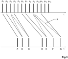
- The MPiA laser scanning system according to the invention is described or explained in more detail below, purely by way of example, with reference to working examples shown schematically in the drawing. Identical elements are labelled with the same reference numerals in the figures. The described embodiments are generally not shown true to scale and they are also not to be interpreted as limiting the invention. Specifically,
- Fig. 1:
- an exemplary embodiment of the inventive MPiA laser scanner in the field of airborne surveying;
- Fig. 2:
- schematically shows the so-called multiple-pulses-in-air (MPiA) problem;
- Fig. 3:
- schematically indicates the transmission of the send pulses and the reception of return pulses corresponding to
Fig. 2 as a function of time t; - Fig. 4:
- schematically shows a first aspect of the invention, wherein the MPiA problem is addressed by range tracking involving range probing;
- Fig. 5:
- exemplarily shows different aspects of post-processing making use of probe shots and range tracking;
- Fig. 6:
- exemplarily shows a second aspect of the invention, wherein an MPiA ambiguity within 2D space is resolved based on an analysis in 3D space.
-
Figure 1 shows an exemplary embodiment of the inventive MPiA laser scanner 1 in the field of airborne surveying, wherein the laser scanner 1 is installed in an airborne carrier, e.g. anairplane 2 or satellite. By way of example, the laser scanner 1 is configured for scanning with a circular scan pattern, e.g. using a rotating tilted deflection mirror, wherein an actualscanner pointing direction 3 is indicated. Due to the circular scanning motion by the laser scanner 1 and the forward flight movement of thecarrier 2, the surface area is drawing aspiral scan pattern 4 on the ground. Thanks to thespiral scan pattern 4 many surface points will be scanned from two viewing angles, thus minimizing shadow effects. - Usually several additional or complementary data sources and measuring devices are used for improving or calibrating the LiDAR measurement, particularly additional means for determining the position and orientation of the
airborne carrier 2, e.g. comprising an altimeter, a device for determining the flight attitude, e.g. giving a yaw angle, a longitudinal angle, and/or a transverse inclination angle of theairplane 2, and measured data of a satellite navigation system carried along in theairplane 2. Furthermore, a known digital 3D model of the overflown terrain might be stored on a central control device of the airplane or on the computing unit of the aerial MPiA laser scanner 1. -
Figure 2 schematically shows the so-called multiple-pulses-in-air (MPiA) problem occurring when the pulse repetition frequency is so high that the time between send pulses is shorter than the time required for an echo to return to the sensor. In this case there are multiple transmit pulses occurring between an initial send pulse and the reception of its echo. - The figure shows an airborne surveying scenario in which a laser scanner has been flown over an underlying terrain, from the left to the right of the figure, wherein in the top illustration return pulses A-G are correctly assigned to respective send pulses, i.e. the terrain - including
vegetation 6 and a steep cliff 7 - is correctly reproduced by the LiDAR scanning. In the bottom illustration some of the return pulses B, C, E, G have been incorrectly assigned and thus lead to wrong time-of-flights of the send pulses. Therefore, the terrain is not correctly mapped, wherein the map comprises "free-floating" points B, E as well as "sub-surface" points G. - Dashed horizontal lines indicate
MPiA zone boundaries 8 according to the exemplary scenario described below forFig. 3 . -
Figure 3 corresponds to the scenario depicted byFig. 2 and schematically indicates the transmission of the send pulses P1-P13 and the reception of return pulses A-G as a function of time t. - Although the first two send pulses P1 and P2 occur over terrain where the correct MPiA zone for the corresponding returns A and B is four, the tall tree encountered by the third send pulse P3 results in a reduction of one MPiA zone for return pulse C. The terrain at send pulse P6 is on the border between MPiA zones three and four due to the rising ground elevation (return pulse D). The steep terrain overflown at send pulses P7-11 results in a rapid transition from MPiA zone three to MPiA zone one for return pulses E, F, and G as the range (and thus the time-of-flight) between the ground and sensor is reduced.
- Tall objects such as trees (return pulse C), steep terrain (return pulses E, F, and G), and even gradual terrain changes (return pulse D), will, in general, lead to MPiA zone transitions that complicate the MPiA problem.
Erroneous disambiguation 9 will lead to incorrect range calculation and the artifacts noted in the lower illustration ofFig. 2 . -
Figure 4 exemplarily shows a first aspect of the invention, wherein the MPiA problem is addressed in that the laser scanner is configured for carrying out a range probing 10 at intermittent points in time, wherein each range probing 10 comprises a time-of-flight arrangement which is laid out to be free of the multiple-pulses-in-air problem, e.g. wherein the pulse repetition frequency is lowered in order to provide for a range cycle which is larger than a flight altitude. On that basis, the MPiA laser scanning system is configured for carrying out the MPiA assignment of the return pulses A-G to respective send pulses P1-P13 (Fig. 3 ) based on range tracking, i.e. taking into account ranges determined by assignments of neighboring return pulses to send pulses, and based on probe values from the range probing 10. - By way of example, as depicted in the top illustration, the laser scanner is configured for generating a spatial scan pattern, here a
circular scan pattern 4, such that it has a transverse extension with respect to aflight direction 11 of the laser scanner. In this example, the laser scanner is configured for carrying out range probing 10 at the extremes of the transverse extension. - Alternatively, the range probing 10 may be carried out at any other fixed or variable repetition rate, e.g. based on a known surface model of the overflown terrain and/or based on a set point density of the LiDAR measurement. For example, as depicted in the bottom illustration, the laser scanner is configured for generating a
zigzag scan pattern 12, wherein range probing 10 is evenly distributed over thespatial scan pattern 12. -
Figure 5 exemplarily shows different aspects of post-processing making use of probe shots 10 (range probings) and range tracking for carrying out the assignment of return pulses to send pulses. The figure shows an airborne surveying scenario in which a laser scanner has been flown over an urban area comprising buildings of different height. - Various return pulses from
probe shots 10 and measurement shots are shown as a function of detection time t of the respective return pulses. - Now referring to the return pulses within the left analysis box B1, the computing unit is configured for carrying out the assignment by taking into account the temporally closest range probing with respect to a return pulse to be assigned. For example, in the transition from the left small building to the skyscraper an ambiguity H' of a return pulse H associated to a hit position on the small building may be resolved by taking into account the temporally closest probe shot 100, such that the
difference 13 between the resulting height and the height indicated by the temporally closest probe shot 100 is minimal. - Now referring to the return pulses within the central analysis box B2, the computing unit is configured for so-called loop closure, i.e. wherein analysis may have started based on a preceding probe shot 101, wherein in a first step range tracking is performed in a sequential way by assigning the next return pulse I to the send pulse such that the difference between the resulting measurement value and the probe value of the initial probe shot 101 is minimal. This procedure is carried forward, comparing each subsequent measurement value to the previous one. However, by taking into account only preceding return pulses an ambiguity K' may still be incorrectly resolved, e.g. wherein the ambiguity K' is resolved based on an estimated slope associated to preceding assignments. Therefore, different heuristics may be employed to make the process more robust to noise or sharp changes of the target surface.
- For example, instead of simply using a sequential procedure as described above, the range probings may also be used for so-called loop closure, e.g. wherein a surface slope is also estimated "backwards" by taking into account another probe shot 102, here the following probe shot, in order to support correct assignment of the return pulse K.
- By way of another example, referring now to the right analysis box B3, a history of tracked returns may be generated in order to approximate, among other things, a
ground level 14, such that an ambiguity L' is immediately discarded as being below the surface in order to correctly assign the corresponding return pulse L. -
Figure 6 exemplarily shows a second aspect of the invention, wherein an MPiA ambiguity within 2D space (top illustration), spanned by sequential time series of return pulses, is converted into the 3D point cloud space (bottom illustration), which provides additional information from the spatial neighborhood of the points in question. - By way of example, a confidence level for the MPiA assignment is determined in 2D space based on a total variation method, wherein the transmitter of the laser scanner is configured for imprinting a regular pulse-position modulation onto the send pulses.
- Based on this assessment a critical area C is identified comprising a set of return pulse assignments with a confidence level below a defined threshold. For example, the 2D assessment may provide reasonable indication that a
first range jump 15, e.g. over only one or two MPiA zones, is associated to a group of trees and thus it is assumed that here the MPiA assignment is correct. However, 2D analysis may not be able to resolve the jump associated with a steep cliff which extends over a multitude of MPiA zones. - Therefore, the problem is transferred to 3D space in that alternative versions of the 3D point cloud section related to the critical area C are generated based on different MPiA zone assignments of the return pulses within the critical area C, so-called
redundant points 16. Theseredundant points 16 are combined with trajectory information and calibration information in order to be positioned asalternative patches 160 within the section S of the 3D point cloud associated to the critical area C. Then, an optimal version of the 3D point cloud section S, i.e. thebest patch 170, is chosen based on comparing thealternative patches 160 with their neighborhood of the point cloud section S. - By way of example, provided that many MPiA zones were already correctly identified in 2D using range tracking from probe shots according to the above described first aspect of the invention, a density measurement may be used to determine the
optimal patch 170. - Although the invention is illustrated above, partly with reference to some preferred embodiments, it must be understood that numerous modifications and combinations of different features of the embodiments can be made. All of these modifications lie within the scope of the appended claims.
Claims (13)
- A multiple-pulses-in-air (MPiA) laser scanning system, particularly for aerial surveying of an overflown terrain, configured for measuring the time-of-flight of laser pulses, comprising• a laser scanner witho a transmitter configured for transmitting a plurality of consecutive laser pulses as send pulses towards a target, ando a receiver configured for detecting the send pulses returning from the target as return pulses,and• a computing unit configured for determining a measurement value indicative of a time-of-flight of a send pulse based on an assignment of one of the return pulses to the send pulse,
characterized in that• the laser scanner is configured for executing a range probing at intermittent points in time, wherein each range probing comprises a time-of-flight arrangement which is constructed to be free of the multiple-pulses-in-air problem, and• the computing unit is configured for carrying out the assignment based on range tracking, wherein the return pulse is assigned to the send pulse by taking into account a measurement value indicative of a time-of-flight determined based on at least another of the return pulses,particularly a preceding return pulse, and by taking into account at least one probe value indicative of a time-of-flight determined based on the range probing as reliable measurement value. - Laser scanning system according to claim 1,
characterized in that
the laser scanner is configured• for directing the send pulses towards the target according to a spatial scan pattern having spatially different scan points, and• for carrying out at least part of the range probing at different scan points of the spatial scan pattern. - Laser scanning system according to claim 2,
characterized in that
the laser scanner is configured for aerial surveying of an overflown terrain, and• for generating the spatial scan pattern such that it has a transverse extension with respect to a flight direction of the laser scanner, particularly wherein the spatial scan pattern is a circular scan pattern or a zigzag scan pattern, and• for carrying out at least part of the range probing at different scan points along the transverse extension, particularly at the extremes of the transverse extension. - Laser scanning system according to any one of the preceding claims,
characterized in thatthe computing unit is configured for carrying out the assignment by taking into account the temporally closest range probing preceding the return pulse, and/or by taking into account the temporally closest range probing succeeding the return pulse,particularly for minimizing and/or compensating drifts in the chronological progress of determined measurement values. - Laser scanning system according to any one of the preceding claims,
characterized in that
the computing unit is configured• for recording a history of probe values determined from different range probings and of measurement values determined based on different return pulses,• for applying a heuristic technique for approximating a shape component of the target based on the history, particularly for approximating a ground level when the laser scanner is configured for aerial surveying, and• for taking into account the shape component for carrying out the assignment. - Laser scanning system according to claim 5,
characterized in that• the computing unit is configured for applying the heuristic technique by means of a moving analysis of the history based on a moving time window comprising multiple return pulses,• wherein the moving time window has a fixed size which is larger than a time interval between consecutive range probings. - Laser scanning system according to any one of the preceding claims,
characterized in that
the computing unit is configured for determining a confidence level of the assignment, wherein the confidence level is determined based on at least one of• a difference between the measurement value and the probe value determined from the temporally closest range probing,• a similarity of different sections of a chronological course of determined measurement values,• a statistical model, and• a mathematical measure. - Laser scanning system according to claim 7,
characterized in that• the laser scanner is configured for imprinting a regular pulse-position modulation onto the send pulses, and• the computing unit is configured for determining the confidence level based on the pulse-position modulation, and a statistical method and/or mathematical measure, particularly a total variation method. - A multiple-pulses-in-air (MPiA) laser scanning system, particularly for aerial surveying of an overflown terrain, according to any one of claims 1 to 8, configured for measuring the time-of-flight of laser pulses, comprising• a laser scanner witho a transmitter configured for transmitting a plurality of consecutive laser pulses as send pulses towards a target, ando a receiver configured for detecting the send pulses returning from the target as return pulses,and• a computing unit configured for determining a measurement value indicative of a time-of-flight of a send pulse based on an initial assignment of one of the return pulses to the send pulse, and for generating a 3D point cloud of the target based on the measurement value and targeting information for the send pulses defined by a scanning pattern of the laser scanner,characterized in that
the computing unit is configured• for carrying out the initial assignment based on range tracking, wherein the return pulse is assigned to the send pulse by taking into account a measurement value indicative of a time-of-flight determined based on at least another return pulse,• for determining a confidence level of the initial assignment, and for generating an alternative assignment of the return pulse to a different send pulse in case the confidence level is below a defined threshold, and• for carrying out a selection of one of the assignments by respectively generating corresponding point cloud sections within the 3D point cloud, and by carrying out a comparison of the point cloud sections with the neighborhood within the 3D point cloud. - Laser scanning system according to claim 9,
characterized in thatthe confidence level is determined based on at least one of a similarity of different sections of a chronological course of determined measurement values, a statistical model, and a mathematical measure,particularly wherein• the laser scanner is configured for imprinting a regular pulse-position modulation onto the send pulses, and• the computing unit is configured for determining the confidence level based on the pulse-position modulation, and a statistical method and/or mathematical measure, particularly a total variation method. - Laser scanning system according to claim 9 or 10,
characterized in that
the selection is based on a density criterion for the 3D point cloud, particularly wherein it is assumed that a correct assignment leads to the highest point density within the 3D point cloud. - Computer program product comprising program code which is stored on a machine-readable medium, or embodied by an electromagnetic wave comprising a program code segment, and has computer-executable instructions for performing, when run on the computing unit of a laser scanning system according to any one of claims 1 to 11, at least the following steps,• carrying out an initial assignment of a return pulse of a laser scanner to a send pulse of the laser scanner based on range tracking, wherein the return pulse is assigned to the send pulse by taking into account a measurement value indicative of a time-of-flight determined based on at least another return pulse of the laser scanner,• determining a confidence level of the initial assignment, and generating an alternative assignment of the return pulse to a different send pulse of the laser scanner in case the confidence level is below a defined threshold,• generating a 3D point cloud based on the initial assignment and targeting information for the send pulses defined by a scanning pattern of the laser scanner, and• carrying out a selection of one of the assignments by respectively generating corresponding point cloud sections within the 3D point cloud, and by carrying out a comparison of the point cloud sections with the neighborhood within the 3D point cloud.
- Computer program product comprising program code which is stored on a machine-readable medium, or embodied by an electromagnetic wave comprising a program code segment, and has computer-executable instructions for performing, when run on the computing unit of a laser scanning system according to any one of claims 1 to 11, at least the step of carrying out an assignment of a return pulse of the laser scanner to a send pulse of the laser scanner based on range tracking, wherein• the return pulse is assigned to the send pulse by taking into account a measurement value indicative of a time-of-flight determined based on at least another return pulse of the laser scanner, particularly a preceding return pulse, and• by taking into account at least one probe value indicative of a time-of-flight determined based on a range probing as reliable measurement value, wherein the range probing comprises a time-of-flight arrangement which is carried out at intermittent points in time by the laser scanner and constructed to be free of the multiple-pulses-in-air problem.
Applications Claiming Priority (1)
| Application Number | Priority Date | Filing Date | Title |
|---|---|---|---|
| US16/160,885 US11513197B2 (en) | 2018-10-15 | 2018-10-15 | Multiple-pulses-in-air laser scanning system with ambiguity resolution based on range probing and 3D point analysis |
Publications (2)
| Publication Number | Publication Date |
|---|---|
| EP3640670A1 EP3640670A1 (en) | 2020-04-22 |
| EP3640670B1 true EP3640670B1 (en) | 2025-07-09 |
Family
ID=68242328
Family Applications (1)
| Application Number | Title | Priority Date | Filing Date |
|---|---|---|---|
| EP19201944.6A Active EP3640670B1 (en) | 2018-10-15 | 2019-10-08 | Multiple-pulses-in-air laser scanning system with ambiguity resolution based on range probing and 3d point analysis |
Country Status (4)
| Country | Link |
|---|---|
| US (1) | US11513197B2 (en) |
| EP (1) | EP3640670B1 (en) |
| CN (1) | CN111123281B (en) |
| DK (1) | DK3640670T3 (en) |
Families Citing this family (9)
| Publication number | Priority date | Publication date | Assignee | Title |
|---|---|---|---|---|
| EP3811113A1 (en) * | 2018-06-22 | 2021-04-28 | Ams Ag | Using time-of-flight and pseudo-random bit sequences to measure distance to object |
| US11513197B2 (en) * | 2018-10-15 | 2022-11-29 | Leica Geosystems Ag | Multiple-pulses-in-air laser scanning system with ambiguity resolution based on range probing and 3D point analysis |
| US12158524B2 (en) * | 2020-12-14 | 2024-12-03 | Luminar Technologies, Inc. | Generating scan patterns using cognitive lidar |
| CN115616596A (en) * | 2021-07-16 | 2023-01-17 | 上海禾赛科技有限公司 | Laser radar ranging method, laser radar, and computer-readable storage medium |
| CN113933912B (en) * | 2021-09-14 | 2023-10-03 | 北京航天控制仪器研究所 | A multi-target high-precision positioning method and system based on UAV platform |
| JP7770893B2 (en) * | 2021-12-13 | 2025-11-17 | 国際航業株式会社 | Ground surface generation system |
| CN116930931A (en) * | 2022-04-11 | 2023-10-24 | 上海禾赛科技有限公司 | Method for evaluating laser radar point cloud drag degree, testing device and laser radar |
| EP4575563A1 (en) | 2023-12-21 | 2025-06-25 | Hexagon Technology Center GmbH | Elliptical pattern generation for scanning instruments |
| EP4657109A1 (en) * | 2024-05-27 | 2025-12-03 | Hexagon Technology Center GmbH | A terrestrial scanning instrument and a method of multiple time around disambiguation |
Citations (1)
| Publication number | Priority date | Publication date | Assignee | Title |
|---|---|---|---|---|
| US20200116833A1 (en) * | 2018-10-15 | 2020-04-16 | Leica Geosystems Ag | Multiple-pulses-in-air laser scanning system with ambiguity resolution based on range probing and 3d point analysis |
Family Cites Families (24)
| Publication number | Priority date | Publication date | Assignee | Title |
|---|---|---|---|---|
| US3409368A (en) * | 1964-01-07 | 1968-11-05 | Martin Marietta Corp | Ranging device |
| IL110611A (en) * | 1994-08-09 | 1997-01-10 | Israel State | Apparatus and method for laser imaging |
| US6963354B1 (en) | 1997-08-07 | 2005-11-08 | The United States Of America As Represented By The Secretary Of The Navy | High resolution imaging lidar for detecting submerged objects |
| US20060238742A1 (en) * | 2005-04-25 | 2006-10-26 | Hunt Jeffrey H | Short duty cycle lidar |
| US7944548B2 (en) * | 2006-03-07 | 2011-05-17 | Leica Geosystems Ag | Increasing measurement rate in time of flight measurement apparatuses |
| EP2253932A1 (en) * | 2009-05-19 | 2010-11-24 | Leica Geosystems AG | Aerial picture camera system and method for correcting distortion in an aerial picture |
| US8344942B2 (en) * | 2010-04-29 | 2013-01-01 | Raytheon Company | System and method for resolving ambiguity in radar, lidar, and acoustic systems |
| AT511310B1 (en) | 2011-04-07 | 2013-05-15 | Riegl Laser Measurement Sys | PROCESS FOR REMOTE MEASUREMENT |
| CN102645209B (en) * | 2012-04-24 | 2014-10-01 | 长江勘测规划设计研究有限责任公司 | Joint positioning method of airborne LiDAR point cloud and high-resolution imagery for spatial points |
| GB2520232A (en) * | 2013-08-06 | 2015-05-20 | Univ Edinburgh | Multiple Event Time to Digital Converter |
| EP2846173B1 (en) * | 2013-09-09 | 2019-06-19 | Trimble AB | Ambiguity compensation in time-of-flight ranging |
| US9575184B2 (en) * | 2014-07-03 | 2017-02-21 | Continental Advanced Lidar Solutions Us, Inc. | LADAR sensor for a dense environment |
| US10088558B2 (en) * | 2014-08-15 | 2018-10-02 | Aeye, Inc. | Method and system for ladar transmission with spiral dynamic scan patterns |
| CN104297743B (en) * | 2014-10-11 | 2017-02-08 | 中国林业科学研究院资源信息研究所 | Method and device for eliminating distance measuring ambiguity of high repetition frequency airborne laser radar system |
| AT517300B1 (en) | 2015-06-15 | 2017-03-15 | Riegl Laser Measurement Systems Gmbh | Method for distance measurement |
| EP3118651B1 (en) * | 2015-07-17 | 2021-04-21 | Hexagon Technology Center GmbH | Time-of-flight measuring device and time-of-flight measuring method with ambiguity solution in real time |
| CN105425245B (en) * | 2015-11-06 | 2018-02-09 | 中国人民解放军空军装备研究院雷达与电子对抗研究所 | A kind of remote Gao Zhongying laser three-dimensional scanning device based on coherent detection |
| EP3182159B1 (en) * | 2015-12-15 | 2018-09-26 | Riegl Laser Measurement Systems GmbH | Distance measuring device |
| US10627490B2 (en) * | 2016-01-31 | 2020-04-21 | Velodyne Lidar, Inc. | Multiple pulse, LIDAR based 3-D imaging |
| EP3206045B1 (en) | 2016-02-15 | 2021-03-31 | Airborne Hydrography AB | Single-photon lidar scanner |
| US10810753B2 (en) * | 2017-02-27 | 2020-10-20 | Microsoft Technology Licensing, Llc | Single-frequency time-of-flight depth computation using stereoscopic disambiguation |
| DE102017002235A1 (en) * | 2017-03-08 | 2018-09-13 | Blickfeld GmbH | LIDAR system with flexible scan parameters |
| US10295668B2 (en) * | 2017-03-30 | 2019-05-21 | Luminar Technologies, Inc. | Reducing the number of false detections in a lidar system |
| US10620301B2 (en) * | 2017-04-04 | 2020-04-14 | Argo AI, LLC | LiDAR system and method employing late-lock Geiger mode detection |
-
2018
- 2018-10-15 US US16/160,885 patent/US11513197B2/en active Active
-
2019
- 2019-10-08 DK DK19201944.6T patent/DK3640670T3/en active
- 2019-10-08 EP EP19201944.6A patent/EP3640670B1/en active Active
- 2019-10-15 CN CN201910977437.3A patent/CN111123281B/en active Active
Patent Citations (1)
| Publication number | Priority date | Publication date | Assignee | Title |
|---|---|---|---|---|
| US20200116833A1 (en) * | 2018-10-15 | 2020-04-16 | Leica Geosystems Ag | Multiple-pulses-in-air laser scanning system with ambiguity resolution based on range probing and 3d point analysis |
Also Published As
| Publication number | Publication date |
|---|---|
| US11513197B2 (en) | 2022-11-29 |
| CN111123281B (en) | 2023-08-11 |
| DK3640670T3 (en) | 2025-10-13 |
| CN111123281A (en) | 2020-05-08 |
| EP3640670A1 (en) | 2020-04-22 |
| US20200116833A1 (en) | 2020-04-16 |
Similar Documents
| Publication | Publication Date | Title |
|---|---|---|
| EP3640670B1 (en) | Multiple-pulses-in-air laser scanning system with ambiguity resolution based on range probing and 3d point analysis | |
| US12345835B2 (en) | LIDAR based distance measurements with tiered power control | |
| US11703569B2 (en) | LIDAR data acquisition and control | |
| CN111492265B (en) | Multi-resolution, simultaneous localization and mapping based on 3D lidar measurements | |
| US10795023B2 (en) | Laser scanning apparatus and method | |
| Thiel et al. | Performance capabilities of laser scanners–an overview and measurement principle analysis | |
| KR102254466B1 (en) | Automatic real-time adaptive scanning method and system using optical distance measurement system | |
| KR102252219B1 (en) | Adaptive scanning method and system using optical distance measurement system | |
| JP7331098B2 (en) | Lidar system and method of operation | |
| EP1832897B1 (en) | LIDAR apparatus with increased pulse repetition rate | |
| US10131446B1 (en) | Addressing multiple time around (MTA) ambiguities, particularly for lidar systems, and particularly for autonomous aircraft | |
| KR101387664B1 (en) | A terrain-aided navigation apparatus using a radar altimeter based on the modified elevation model | |
| EP1405095B1 (en) | Apparatus and method of tracking objects in flight | |
| US7315280B2 (en) | Coherent geolocation system | |
| CN107817501B (en) | Point cloud data processing method with variable scanning frequency | |
| CN115792934A (en) | Airborne laser scanner | |
| US20240201380A1 (en) | Unambiguous laser scanning data from scanning with two pulse frequencies | |
| CN115407303B (en) | Laser radar distance ambiguity elimination method | |
| CN107817499A (en) | A kind of Processing Method of Point-clouds based on dual radars | |
| RU2536320C1 (en) | Method of navigation of aircrafts | |
| KR102861346B1 (en) | Method and Apparatus for LiDAR Signal Processing Using Multiple Beams | |
| RU2755650C1 (en) | Method for scanning underlying surface along course | |
| RU2358281C1 (en) | Method of measuring angular coordinates of object and radar station for its realisation | |
| RU2681303C1 (en) | Method of aircraft navigation | |
| CN121026002A (en) | Unambiguous laser scanning data using overlapping scan domains |
Legal Events
| Date | Code | Title | Description |
|---|---|---|---|
| PUAI | Public reference made under article 153(3) epc to a published international application that has entered the european phase |
Free format text: ORIGINAL CODE: 0009012 |
|
| STAA | Information on the status of an ep patent application or granted ep patent |
Free format text: STATUS: THE APPLICATION HAS BEEN PUBLISHED |
|
| AK | Designated contracting states |
Kind code of ref document: A1 Designated state(s): AL AT BE BG CH CY CZ DE DK EE ES FI FR GB GR HR HU IE IS IT LI LT LU LV MC MK MT NL NO PL PT RO RS SE SI SK SM TR |
|
| AX | Request for extension of the european patent |
Extension state: BA ME |
|
| STAA | Information on the status of an ep patent application or granted ep patent |
Free format text: STATUS: REQUEST FOR EXAMINATION WAS MADE |
|
| 17P | Request for examination filed |
Effective date: 20200821 |
|
| RBV | Designated contracting states (corrected) |
Designated state(s): AL AT BE BG CH CY CZ DE DK EE ES FI FR GB GR HR HU IE IS IT LI LT LU LV MC MK MT NL NO PL PT RO RS SE SI SK SM TR |
|
| STAA | Information on the status of an ep patent application or granted ep patent |
Free format text: STATUS: EXAMINATION IS IN PROGRESS |
|
| 17Q | First examination report despatched |
Effective date: 20211217 |
|
| GRAP | Despatch of communication of intention to grant a patent |
Free format text: ORIGINAL CODE: EPIDOSNIGR1 |
|
| STAA | Information on the status of an ep patent application or granted ep patent |
Free format text: STATUS: GRANT OF PATENT IS INTENDED |
|
| INTG | Intention to grant announced |
Effective date: 20250210 |
|
| GRAS | Grant fee paid |
Free format text: ORIGINAL CODE: EPIDOSNIGR3 |
|
| GRAA | (expected) grant |
Free format text: ORIGINAL CODE: 0009210 |
|
| STAA | Information on the status of an ep patent application or granted ep patent |
Free format text: STATUS: THE PATENT HAS BEEN GRANTED |
|
| AK | Designated contracting states |
Kind code of ref document: B1 Designated state(s): AL AT BE BG CH CY CZ DE DK EE ES FI FR GB GR HR HU IE IS IT LI LT LU LV MC MK MT NL NO PL PT RO RS SE SI SK SM TR |
|
| REG | Reference to a national code |
Ref country code: GB Ref legal event code: FG4D |
|
| REG | Reference to a national code |
Ref country code: CH Ref legal event code: EP |
|
| REG | Reference to a national code |
Ref country code: IE Ref legal event code: FG4D |
|
| REG | Reference to a national code |
Ref country code: DE Ref legal event code: R096 Ref document number: 602019072228 Country of ref document: DE |
|
| REG | Reference to a national code |
Ref country code: DK Ref legal event code: T3 Effective date: 20251009 |
|
| REG | Reference to a national code |
Ref country code: NL Ref legal event code: MP Effective date: 20250709 |
|
| PG25 | Lapsed in a contracting state [announced via postgrant information from national office to epo] |
Ref country code: PT Free format text: LAPSE BECAUSE OF FAILURE TO SUBMIT A TRANSLATION OF THE DESCRIPTION OR TO PAY THE FEE WITHIN THE PRESCRIBED TIME-LIMIT Effective date: 20251110 |
|
| PG25 | Lapsed in a contracting state [announced via postgrant information from national office to epo] |
Ref country code: NL Free format text: LAPSE BECAUSE OF FAILURE TO SUBMIT A TRANSLATION OF THE DESCRIPTION OR TO PAY THE FEE WITHIN THE PRESCRIBED TIME-LIMIT Effective date: 20250709 |
|
| PG25 | Lapsed in a contracting state [announced via postgrant information from national office to epo] |
Ref country code: IS Free format text: LAPSE BECAUSE OF FAILURE TO SUBMIT A TRANSLATION OF THE DESCRIPTION OR TO PAY THE FEE WITHIN THE PRESCRIBED TIME-LIMIT Effective date: 20251109 |
|
| PGFP | Annual fee paid to national office [announced via postgrant information from national office to epo] |
Ref country code: DE Payment date: 20251021 Year of fee payment: 7 |
|
| PG25 | Lapsed in a contracting state [announced via postgrant information from national office to epo] |
Ref country code: NO Free format text: LAPSE BECAUSE OF FAILURE TO SUBMIT A TRANSLATION OF THE DESCRIPTION OR TO PAY THE FEE WITHIN THE PRESCRIBED TIME-LIMIT Effective date: 20251009 |
|
| REG | Reference to a national code |
Ref country code: LT Ref legal event code: MG9D |
|
| PGFP | Annual fee paid to national office [announced via postgrant information from national office to epo] |
Ref country code: AT Payment date: 20251022 Year of fee payment: 7 |
|
| PG25 | Lapsed in a contracting state [announced via postgrant information from national office to epo] |
Ref country code: FI Free format text: LAPSE BECAUSE OF FAILURE TO SUBMIT A TRANSLATION OF THE DESCRIPTION OR TO PAY THE FEE WITHIN THE PRESCRIBED TIME-LIMIT Effective date: 20250709 |
|
| PGFP | Annual fee paid to national office [announced via postgrant information from national office to epo] |
Ref country code: DK Payment date: 20251027 Year of fee payment: 7 |
|
| PG25 | Lapsed in a contracting state [announced via postgrant information from national office to epo] |
Ref country code: HR Free format text: LAPSE BECAUSE OF FAILURE TO SUBMIT A TRANSLATION OF THE DESCRIPTION OR TO PAY THE FEE WITHIN THE PRESCRIBED TIME-LIMIT Effective date: 20250709 |
|
| PG25 | Lapsed in a contracting state [announced via postgrant information from national office to epo] |
Ref country code: GR Free format text: LAPSE BECAUSE OF FAILURE TO SUBMIT A TRANSLATION OF THE DESCRIPTION OR TO PAY THE FEE WITHIN THE PRESCRIBED TIME-LIMIT Effective date: 20251010 |
|
| PG25 | Lapsed in a contracting state [announced via postgrant information from national office to epo] |
Ref country code: SE Free format text: LAPSE BECAUSE OF FAILURE TO SUBMIT A TRANSLATION OF THE DESCRIPTION OR TO PAY THE FEE WITHIN THE PRESCRIBED TIME-LIMIT Effective date: 20250709 |
|
| PG25 | Lapsed in a contracting state [announced via postgrant information from national office to epo] |
Ref country code: LV Free format text: LAPSE BECAUSE OF FAILURE TO SUBMIT A TRANSLATION OF THE DESCRIPTION OR TO PAY THE FEE WITHIN THE PRESCRIBED TIME-LIMIT Effective date: 20250709 |
|
| PG25 | Lapsed in a contracting state [announced via postgrant information from national office to epo] |
Ref country code: BG Free format text: LAPSE BECAUSE OF FAILURE TO SUBMIT A TRANSLATION OF THE DESCRIPTION OR TO PAY THE FEE WITHIN THE PRESCRIBED TIME-LIMIT Effective date: 20250709 Ref country code: PL Free format text: LAPSE BECAUSE OF FAILURE TO SUBMIT A TRANSLATION OF THE DESCRIPTION OR TO PAY THE FEE WITHIN THE PRESCRIBED TIME-LIMIT Effective date: 20250709 |
|
| PG25 | Lapsed in a contracting state [announced via postgrant information from national office to epo] |
Ref country code: RS Free format text: LAPSE BECAUSE OF FAILURE TO SUBMIT A TRANSLATION OF THE DESCRIPTION OR TO PAY THE FEE WITHIN THE PRESCRIBED TIME-LIMIT Effective date: 20251009 |
|
| PG25 | Lapsed in a contracting state [announced via postgrant information from national office to epo] |
Ref country code: ES Free format text: LAPSE BECAUSE OF FAILURE TO SUBMIT A TRANSLATION OF THE DESCRIPTION OR TO PAY THE FEE WITHIN THE PRESCRIBED TIME-LIMIT Effective date: 20250709 |
|
| PG25 | Lapsed in a contracting state [announced via postgrant information from national office to epo] |
Ref country code: RO Free format text: LAPSE BECAUSE OF FAILURE TO SUBMIT A TRANSLATION OF THE DESCRIPTION OR TO PAY THE FEE WITHIN THE PRESCRIBED TIME-LIMIT Effective date: 20250709 |
|
| PG25 | Lapsed in a contracting state [announced via postgrant information from national office to epo] |
Ref country code: SM Free format text: LAPSE BECAUSE OF FAILURE TO SUBMIT A TRANSLATION OF THE DESCRIPTION OR TO PAY THE FEE WITHIN THE PRESCRIBED TIME-LIMIT Effective date: 20250709 |
|
| PG25 | Lapsed in a contracting state [announced via postgrant information from national office to epo] |
Ref country code: IT Free format text: LAPSE BECAUSE OF FAILURE TO SUBMIT A TRANSLATION OF THE DESCRIPTION OR TO PAY THE FEE WITHIN THE PRESCRIBED TIME-LIMIT Effective date: 20250709 |
|
| PG25 | Lapsed in a contracting state [announced via postgrant information from national office to epo] |
Ref country code: CZ Free format text: LAPSE BECAUSE OF FAILURE TO SUBMIT A TRANSLATION OF THE DESCRIPTION OR TO PAY THE FEE WITHIN THE PRESCRIBED TIME-LIMIT Effective date: 20250709 |
|
| PG25 | Lapsed in a contracting state [announced via postgrant information from national office to epo] |
Ref country code: SK Free format text: LAPSE BECAUSE OF FAILURE TO SUBMIT A TRANSLATION OF THE DESCRIPTION OR TO PAY THE FEE WITHIN THE PRESCRIBED TIME-LIMIT Effective date: 20250709 Ref country code: EE Free format text: LAPSE BECAUSE OF FAILURE TO SUBMIT A TRANSLATION OF THE DESCRIPTION OR TO PAY THE FEE WITHIN THE PRESCRIBED TIME-LIMIT Effective date: 20250709 |