EP3640579A1 - Rotation detection device - Google Patents
Rotation detection device Download PDFInfo
- Publication number
- EP3640579A1 EP3640579A1 EP18817574.9A EP18817574A EP3640579A1 EP 3640579 A1 EP3640579 A1 EP 3640579A1 EP 18817574 A EP18817574 A EP 18817574A EP 3640579 A1 EP3640579 A1 EP 3640579A1
- Authority
- EP
- European Patent Office
- Prior art keywords
- wheel
- shaft body
- rotational axis
- detection device
- tubular
- Prior art date
- Legal status (The legal status is an assumption and is not a legal conclusion. Google has not performed a legal analysis and makes no representation as to the accuracy of the status listed.)
- Granted
Links
Images






Classifications
-
- G—PHYSICS
- G01—MEASURING; TESTING
- G01D—MEASURING NOT SPECIALLY ADAPTED FOR A SPECIFIC VARIABLE; ARRANGEMENTS FOR MEASURING TWO OR MORE VARIABLES NOT COVERED IN A SINGLE OTHER SUBCLASS; TARIFF METERING APPARATUS; MEASURING OR TESTING NOT OTHERWISE PROVIDED FOR
- G01D5/00—Mechanical means for transferring the output of a sensing member; Means for converting the output of a sensing member to another variable where the form or nature of the sensing member does not constrain the means for converting; Transducers not specially adapted for a specific variable
- G01D5/12—Mechanical means for transferring the output of a sensing member; Means for converting the output of a sensing member to another variable where the form or nature of the sensing member does not constrain the means for converting; Transducers not specially adapted for a specific variable using electric or magnetic means
- G01D5/14—Mechanical means for transferring the output of a sensing member; Means for converting the output of a sensing member to another variable where the form or nature of the sensing member does not constrain the means for converting; Transducers not specially adapted for a specific variable using electric or magnetic means influencing the magnitude of a current or voltage
-
- G—PHYSICS
- G01—MEASURING; TESTING
- G01B—MEASURING LENGTH, THICKNESS OR SIMILAR LINEAR DIMENSIONS; MEASURING ANGLES; MEASURING AREAS; MEASURING IRREGULARITIES OF SURFACES OR CONTOURS
- G01B7/00—Measuring arrangements characterised by the use of electric or magnetic techniques
- G01B7/30—Measuring arrangements characterised by the use of electric or magnetic techniques for measuring angles or tapers; for testing the alignment of axes
-
- G—PHYSICS
- G01—MEASURING; TESTING
- G01D—MEASURING NOT SPECIALLY ADAPTED FOR A SPECIFIC VARIABLE; ARRANGEMENTS FOR MEASURING TWO OR MORE VARIABLES NOT COVERED IN A SINGLE OTHER SUBCLASS; TARIFF METERING APPARATUS; MEASURING OR TESTING NOT OTHERWISE PROVIDED FOR
- G01D5/00—Mechanical means for transferring the output of a sensing member; Means for converting the output of a sensing member to another variable where the form or nature of the sensing member does not constrain the means for converting; Transducers not specially adapted for a specific variable
- G01D5/12—Mechanical means for transferring the output of a sensing member; Means for converting the output of a sensing member to another variable where the form or nature of the sensing member does not constrain the means for converting; Transducers not specially adapted for a specific variable using electric or magnetic means
- G01D5/14—Mechanical means for transferring the output of a sensing member; Means for converting the output of a sensing member to another variable where the form or nature of the sensing member does not constrain the means for converting; Transducers not specially adapted for a specific variable using electric or magnetic means influencing the magnitude of a current or voltage
- G01D5/142—Mechanical means for transferring the output of a sensing member; Means for converting the output of a sensing member to another variable where the form or nature of the sensing member does not constrain the means for converting; Transducers not specially adapted for a specific variable using electric or magnetic means influencing the magnitude of a current or voltage using Hall-effect devices
- G01D5/145—Mechanical means for transferring the output of a sensing member; Means for converting the output of a sensing member to another variable where the form or nature of the sensing member does not constrain the means for converting; Transducers not specially adapted for a specific variable using electric or magnetic means influencing the magnitude of a current or voltage using Hall-effect devices influenced by the relative movement between the Hall device and magnetic fields
-
- G—PHYSICS
- G01—MEASURING; TESTING
- G01D—MEASURING NOT SPECIALLY ADAPTED FOR A SPECIFIC VARIABLE; ARRANGEMENTS FOR MEASURING TWO OR MORE VARIABLES NOT COVERED IN A SINGLE OTHER SUBCLASS; TARIFF METERING APPARATUS; MEASURING OR TESTING NOT OTHERWISE PROVIDED FOR
- G01D2205/00—Indexing scheme relating to details of means for transferring or converting the output of a sensing member
- G01D2205/20—Detecting rotary movement
- G01D2205/28—The target being driven in rotation by additional gears
-
- G—PHYSICS
- G01—MEASURING; TESTING
- G01D—MEASURING NOT SPECIALLY ADAPTED FOR A SPECIFIC VARIABLE; ARRANGEMENTS FOR MEASURING TWO OR MORE VARIABLES NOT COVERED IN A SINGLE OTHER SUBCLASS; TARIFF METERING APPARATUS; MEASURING OR TESTING NOT OTHERWISE PROVIDED FOR
- G01D5/00—Mechanical means for transferring the output of a sensing member; Means for converting the output of a sensing member to another variable where the form or nature of the sensing member does not constrain the means for converting; Transducers not specially adapted for a specific variable
- G01D5/12—Mechanical means for transferring the output of a sensing member; Means for converting the output of a sensing member to another variable where the form or nature of the sensing member does not constrain the means for converting; Transducers not specially adapted for a specific variable using electric or magnetic means
- G01D5/244—Mechanical means for transferring the output of a sensing member; Means for converting the output of a sensing member to another variable where the form or nature of the sensing member does not constrain the means for converting; Transducers not specially adapted for a specific variable using electric or magnetic means influencing characteristics of pulses or pulse trains; generating pulses or pulse trains
- G01D5/24428—Error prevention
- G01D5/24433—Error prevention by mechanical means
Definitions
- the present invention relates to a rotation detection device that detects an angle by which a shaft body has rotated about a central axis thereof.
- PTL 1 describes a rotational angle detection device including a rotor that rotates together with a steering shaft when the steering shaft rotates and a support body disposed outside a tubular portion of the rotor.
- the rotational angle detection device is disposed in a case in such a manner that the tubular portion of the rotor is inserted in an insertion hole in the support body.
- the rotor includes a disc portion that extends outward from the tubular portion and engagement projections that project inward.
- a detection object is provided on a peripheral surface of the disc portion.
- the support body includes a cylindrical portion and a sensor support portion that projects outward from the cylindrical portion. A sensor is fixed to the sensor support portion so that the sensor faces the peripheral surface of the disc portion of the rotor.
- the steering shaft has a pair of grooves formed in a peripheral surface thereof so as to extend in an axial direction, and is inserted in the tubular portion in such a manner that the engagement projections of the rotor are engaged with the grooves.
- the tubular portion of the rotor may project inward beyond extension of an inner peripheral surface of a hole formed in the case due to errors in attachment of the rotor to the case or manufacturing errors in the shape of the rotor.
- the steering shaft is inserted into the hole in the case in such a state, there is a risk that the steering shaft will come into contact with the tubular portion of the rotor that projects inward.
- damage to the rotor, the support body, or the steering shaft and displacement between the rotor and the support body may occur.
- an object of the present invention is to provide a rotation detection device including a rotor to be engaged with a shaft body that serves as a detection object, the rotation detection device being capable of preventing contact between the shaft body and the rotor even when the rotor has attachment errors or manufacturing errors, or capable of reducing damage to and displacements of components even when the contact occurs.
- a rotation detection device includes a housing portion; a wheel portion having a rotational axis and retained by the housing portion such that the wheel portion is rotatable about the rotational axis; a magnet body retained by the housing portion, the magnet body rotating in response to rotation of the wheel portion so that a magnetic field of the magnet body changes; and a magnetic detection portion disposed on the housing portion at a position corresponding to a position of the magnet body, the magnetic detection portion detecting the magnetic field of the magnet body.
- the wheel portion allows a shaft body that serves as a detection object to be inserted therein in a direction of the rotational axis from a position in front of the wheel portion, and is rotated about the rotational axis when the shaft body is rotated.
- the wheel portion includes a tubular portion in which the shaft body is inserted and a projecting edge portion extending away from the rotational axis at a front end of the tubular portion.
- the housing portion includes a cover portion having a hollow tubular opening portion in which the shaft body is inserted. The cover portion and the wheel portion are engaged with each other such that the opening portion is located on an inner side of the projecting edge portion.
- the shaft body when the shaft body is inserted into the rotation detection device, the shaft body comes into contact more easily with the cover portion, which is disposed on an outer side of the wheel portion, than with the wheel portion. Therefore, the wheel portion is prevented from receiving a strong impact.
- a ridge portion between an inner peripheral surface of the tubular portion and the projecting edge portion is preferably chamfered.
- an inner peripheral surface of the opening portion preferably includes a guide surface shaped such that an inner diameter of the guide surface decreases with increasing distance toward a downstream side in a direction in which the shaft body is inserted.
- the shaft body can be smoothly guided into the device, and can be prevented from coming into contact with components such as the wheel portion.
- the projecting edge portion includes a step portion forming a small diameter portion at a downstream side in a direction in which the shaft body is inserted and a large diameter portion located upstream of the small diameter portion and having an inner diameter greater than an inner diameter of the small diameter portion, and the opening portion is engaged with the step portion so that the cover portion and the wheel portion are joined together.
- the wheel portion can be easily retained by the cover portion, and the rotation of the wheel portion can be stabilized.
- the opening portion can be easily disposed on the inner side of the wheel portion, so that the shaft body can be easily prevented from coming into contact with the wheel portion.
- FIGS. 1 and 2 are perspective views illustrating the structure of a rotation detection device 10 according to the present embodiment.
- Fig. 1 shows a view from the front (D1 side in Fig. 1 ), and
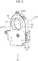
- Fig. 2 shows a view from the rear (D2 side in Fig. 1 ).
- Fig. 3 is a front perspective view illustrating the structure of a case portion 40.
- Fig. 4 shows perspective views illustrating the structure of a wheel portion 50.
- Fig. 4(A) shows a view from the front
- Fig. 4(B) shows a view from the rear.
- Fig. 1 and 2 are perspective views illustrating the structure of a rotation detection device 10 according to the present embodiment.
- Fig. 1 shows a view from the front (D1 side in Fig. 1 )
- Fig. 2 shows a view from the rear (D2 side in Fig. 1 ).
- Fig. 3 is a front perspective view illustrating the structure of a case portion 40.
- FIG. 5 is an enlarged partial sectional view illustrating the structure of a tubular portion 51 and a projecting edge portion 52 of the wheel portion 50.
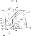
- Fig. 6 is an enlarged partial sectional view illustrating a state in which the wheel portion 50 is retained in a housing portion 20.
- the D1 direction is the forward direction and the D2 direction is the rearward direction.
- a view in the front-to-rear direction may be referred to as a plan view.
- the rotation detection device 10 includes the housing portion 20 and the wheel portion 50 retained by the housing portion 20.
- the housing portion 20 is formed by joining a cover portion 30 disposed at the front and the case portion 40 disposed at the rear together in the front-rear direction.
- the housing portion 20 and the wheel portion 50 may be formed of various materials.
- the housing portion 20 may be formed of polybutadiene terephthalate (PBT), and the wheel portion 50 may be formed of polyacetal or polyoxymethylene (POM). In such a case, abrasion between these materials can be reduced owing to the difference therebetween in the modulus of elasticity.
- the cover portion 30 has an opening portion 31 extending therethrough in the front-rear direction (D1-D2 direction) and having a circular shape in plan view. As illustrated in Figs. 1 and 6 (in Fig. 6 , the D1 direction is upward in the drawing), the opening portion 31 includes an inclined portion 32 having a diameter that decreases with increasing distance in the front-to-rear direction and an annular portion 33 that extends from the rear end of the inclined portion 32 in a thin plate shape in the front-rear direction.
- the inclined portion 32 has an inner surface 32a that serves as a guide surface that guides a shaft body B inserted into the housing portion 20.
- the case portion 40 has an opening portion 43 extending therethrough in the front-rear direction and having a circular shape in plan view.
- the opening portion 43 is at a position corresponding to the position of the opening portion 31 of the cover portion 30.
- the opening portion 31 of the cover portion 30 and the opening portion 43 of the case portion 40 are arranged so that central axes thereof coincide and extend in the front-rear direction.
- These two opening portions 31 and 43 define an opening 20a ( Fig. 1 ) that extends through the housing portion 20 in the front-rear direction.
- Two shaft portions 41 and 42 which each extend forward are provided on a front surface 40a of the case portion 40 in a region below the opening portion 43.
- the front side (D1 side) is the upstream side in the direction in which the shaft body B is inserted
- the rear side (D2 side) is the downstream side in the direction in which the shaft body B is inserted.
- the wheel portion 50 which serves as a rotor, is retained by the housing portion 20 in such a manner that the wheel portion 50 is rotatable about a rotational axis AX.
- the wheel portion 50 has a circular shape in plan view, and is arranged concentrically to the opening portion 31 of the cover portion 30 and the opening portion 43 of the case portion 40 with the rotational axis AX serving as the central axis.
- the rotational axis AX of the wheel portion 50 is arranged to extend in the front-rear direction (D1-D2 direction).
- the shaft body B and the wheel portion 50 are in spline engagement with each other.
- a projection provided on the shaft body B and a recess provided in the wheel portion 50 are fitted together to form a joined portion. Accordingly, when the shaft body B is rotated about a rotational axis thereof, the wheel portion 50 also rotates about the rotational axis AX thereof.
- the attachment portion may, for example, have a member (hereinafter referred to as an interlocking member) into which the shaft body B is inserted, similarly to the tubular portion 51, and that rotates in response to rotation of the shaft body B.
- an interlocking member may be connected to the shaft portion B, and one end of the wheel portion 50 (tubular portion 51) may be connected to the interlocking member so that the wheel portion 50 rotates in response to rotation of the shaft portion B.
- the wheel portion 50 includes the tubular portion 51, which is hollow and has the rotational axis AX as the central axis thereof, and the projecting edge portion 52, which extends toward an outer side from the front end of the tubular portion 51.
- the projecting edge portion 52 is formed to extend in directions away from the rotational axis AX.
- the outer side means the side away from the rotational axis AX
- the inner side means the side toward the rotational axis AX.
- the projecting edge portion 52 includes a small diameter portion 53, a large diameter portion 54, and a step portion 55.
- the small diameter portion 53 is formed to extend toward the outer side from a front end portion 51a of the tubular portion 51, and has an annular shape.
- the small diameter portion 53 has teeth 53b with a predetermined pitch on an outer peripheral surface thereof (see Fig. 9 ).
- a ridge portion 53a between an inner peripheral surface 51b of the tubular portion 51 and the small diameter portion 53 is chamfered. Accordingly, even when the shaft body B that is being inserted comes into contact with the ridge portion 53a, the possibility that the shaft body B or the wheel portion 50 will be damaged or the assembly positions thereof will be displaced can be reduced.
- the step portion 55 extends forward (toward the D1 side) from an outer end of the small diameter portion 53.
- the large diameter portion 54 is formed to extend toward the outer side from a front end portion 55a of the step portion 55.
- the large diameter portion 54 has an annular shape with an inner diameter greater than that of the small diameter portion 53, and has teeth 54b with a pitch equal to that of the teeth 53b of the small diameter portion 53 on an outer peripheral surface thereof (see Fig. 9 ).
- the teeth 53b of the small diameter portion 53 and the teeth 54b of the large diameter portion 54 are arranged at positions corresponding to each other in the circumferential direction.
- a ridge portion 54a between an inner peripheral surface 55b of the step portion 55 and the large diameter portion 54 is also chamfered.
- the ridge portion 54a is chamfered, even when the outer surface of the opening portion 31 comes into contact with the ridge portion 54a upon engagement between the cover portion 30 and the wheel portion 50, the possibility of damage to the cover portion 30 or the wheel portion 50 can be reduced, and sufficient assembly accuracy can be ensured.
- the pitch of the teeth 53b of the small diameter portion 53 and the pitch of the teeth 54b of the large diameter portion 54 are not necessarily equal.
- the wheel portion 50 is retained between the cover portion 30 and the case portion 40 in the front-rear direction (D1-D2 direction). More specifically, in a rear section (D2-side section) of the wheel portion 50, the small diameter portion 53 is supported by the case portion 40 positioned therebehind, and the tubular portion 51 is supported by an inner peripheral surface of the opening portion 43. The tubular portion 51 extends rearward (in the D2 direction) beyond the opening portion 43.
- the annular portion 33 of the opening portion 31 is disposed on the inner side of (closer to the center than) the step portion 55, and the inner peripheral surface 55b of the step portion 55 and the annular portion 33 of the opening portion 31 extend parallel to each other in the front-rear direction.
- the annular portion 33 of the opening portion 31 is located on an L-shaped bent portion formed by the tubular portion 51 and the step portion 55, so that movement of the wheel portion 50 in the front-rear direction is restrained. As illustrated in Fig.
- the inner peripheral surface 33a of the annular portion 33 is at substantially the same position as the inner peripheral surface 51b of the tubular portion 51 in a direction orthogonal to the front-rear direction (left-right direction in Fig. 6 ). Therefore, the inner surface of the opening 20a has small irregularities.
- the shaft body B is inserted into the housing portion 20 assembled as described above from a position in front of (on the D1-side of) the opening 20a (opening portion 31 of the cover portion 30). Even when the wheel portion 50 has attachment errors or manufacturing errors in shape, the shaft body B can be prevented from coming into hard contact with the wheel portion 50 because the ridge portion 53a between the tubular portion 51 and the small diameter portion 53 is chamfered. Accordingly, the possibilities of damage to the shaft body B or the wheel portion 50 and displacements between the cover portion 30, the case portion 40, and the wheel portion 50 can be reduced. In addition, since the opening portion 31 of the cover portion 30 includes the inclined portion 32 having the inner surface 32a that serves as a guide surface, the shaft body B can be smoothly guided rearward through the opening 20a.
- the inner peripheral surface 33a of the annular portion 33 and the inner peripheral surface 51b of the tubular portion 51 are arranged at substantially the same position in a direction orthogonal to the front-rear direction. Therefore, when the shaft body B is advanced into the wheel portion 50 from the space inside the opening portion 31 of the cover portion 30, the shaft body B can be smoothly inserted with less risk of interference with the inner peripheral surface 51b of the wheel portion 50. In addition, when the shaft body B is inserted into the wheel portion 50, the shaft body B is guided by the annular portion 33 until the shaft body B reaches the position of the inner peripheral surface 51b. Therefore, the possibility that the shaft body B will come into direct contact with the wheel portion 50 is further reduced. Accordingly, force is not easily applied in a direction for cancelling the engagement between the cover portion 30 and the case portion 40.
- the annular portion 33 of the cover portion 30 and the wheel portion 50 have a gap G1 therebetween in the front-rear direction and a gap G2 therebetween in a direction orthogonal to the front-rear direction. Therefore, even when the shaft body B that is being inserted comes into contact with the opening portion 31, the impact is not easily transmitted to the wheel portion 50, so that the occurrence of, for example, damage to and displacement of the wheel portion 50 can be reduced. In addition, when the wheel portion 50 rotates together with the shaft body B, abrasion of the annular portion 33 can be prevented. In addition, a large space is provided between the inclined portion 32 of the cover portion 30 and the wheel portion 50 on the inner side of the inclined portion 32. Therefore, even when the shaft body B comes into contact with the inclined portion 32, the impact is not easily transmitted to the wheel portion 50.
- Fig. 7 is a rear perspective view of the cover portion 30.
- Fig. 8 is a front perspective view illustrating a state in which the cover portion 30 is removed.
- Fig. 9 is a rear perspective view illustrating a state in which the case portion 40 is removed.
- Fig. 10 is an enlarged partial sectional view illustrating the relationship between a magnetic detection portion 71 and a magnet body 61.
- a circuit board and other components are not illustrated.
- the D3 direction is the upward direction and the D4 direction is the downward direction.
- the case portion 40 has two shaft portions 41 and 42.
- the cover portion 30 has two magnetic detection portions 71 and 72 at positions corresponding to the positions of the shaft portions 41 and 42 when the cover portion 30 is joined to the case portion 40.
- the magnetic detection portions 71 and 72 may be various magnetic sensors, such as Hall elements or magnetoresistive elements.
- the shaft portions 41 and 42 respectively support gears 41a and 42a, and the gears 41a and 42a are respectively rotatable about the shaft portions 41 and 42.
- a first magnet body 61 is fixed in the gear 41a
- a second magnet body 62 is fixed in the gear 42a.
- the outer shape of the magnet bodies 61 and 62 is a substantially square loop shape in plan view, and the shaft portions 41 and 42 are disposed at the centers of the loops. In other words, the magnet bodies 61 and 62 are arranged to be rotatable about the shaft portions 41 and 42 together with the gears 41a and 42a.
- the outer shape of the magnet bodies 61 and 62 in plan view may instead be a polygonal shape other than the substantially square shape or an annular shape.
- the gear 41a has teeth 41b with a predetermined pitch on an outer peripheral surface thereof, and is arranged to mesh with the teeth 54b of the wheel portion 50.
- the gear 42a has teeth 42b with a predetermined pitch on an outer peripheral surface thereof, and is arranged to mesh with the teeth 53b of the wheel portion 50.
- the gear 41a that meshes with the teeth 54b of the wheel portion 50 rotates about the shaft portion 41
- the gear 42a that meshes with the teeth 53b rotates about the shaft portion 42.
- the magnetic detection portion 71 is positioned to face the shaft portion 41, and the magnet body 61 is disposed so that the shaft portion 41 is positioned between portions thereof.
- the magnet body 61 illustrated in Fig. 10 may have an N-pole in an upper region 61a thereof and an S-pole in a lower region 61b thereof.
- lines of magnetic force extend from the N-pole to the S-pole
- the magnetic detection portion 71 which is located at an intermediate position along the lines of magnetic force, measures the magnitude and direction of the magnetic field generated by the magnet body 61.
- the structure and operation of the magnet body 62 are similar to those of the magnet body 61 described above.
- the structures of the magnet body 61 and the magnet body 62 are not limited to the above-described structure.
- the inner peripheral surface 33a of the annular portion 33 of the opening portion 31 is at substantially the same position as the inner peripheral surface 51b of the tubular portion 51 of the wheel portion 50 in a direction orthogonal to the front-rear direction.
- the inner peripheral surface 33a of the annular portion 33 may instead be disposed on the inner side of the inner peripheral surface 51b of the tubular portion 51.
- a rotation detection device is advantageously capable of preventing contact between a shaft body and a rotor even when a wheel portion, which serves as the rotor, has attachment errors or manufacturing errors, or capable of reducing damage to and displacements of the components even when the contact occurs.
Landscapes
- Physics & Mathematics (AREA)
- General Physics & Mathematics (AREA)
- Transmission And Conversion Of Sensor Element Output (AREA)
- Measurement Of Length, Angles, Or The Like Using Electric Or Magnetic Means (AREA)
Abstract
Description
- The present invention relates to a rotation detection device that detects an angle by which a shaft body has rotated about a central axis thereof.
-
PTL 1 describes a rotational angle detection device including a rotor that rotates together with a steering shaft when the steering shaft rotates and a support body disposed outside a tubular portion of the rotor. The rotational angle detection device is disposed in a case in such a manner that the tubular portion of the rotor is inserted in an insertion hole in the support body. The rotor includes a disc portion that extends outward from the tubular portion and engagement projections that project inward. A detection object is provided on a peripheral surface of the disc portion. The support body includes a cylindrical portion and a sensor support portion that projects outward from the cylindrical portion. A sensor is fixed to the sensor support portion so that the sensor faces the peripheral surface of the disc portion of the rotor. The steering shaft has a pair of grooves formed in a peripheral surface thereof so as to extend in an axial direction, and is inserted in the tubular portion in such a manner that the engagement projections of the rotor are engaged with the grooves. According to this structure, when the rotor rotates in response to rotation of the steering shaft, movement of the detection object is detected by the sensor. - PTL 1: Japanese Unexamined Patent Application Publication No.
11-51636 - However, according to the rotational angle detection device of
PTL 1, the tubular portion of the rotor may project inward beyond extension of an inner peripheral surface of a hole formed in the case due to errors in attachment of the rotor to the case or manufacturing errors in the shape of the rotor. When the steering shaft is inserted into the hole in the case in such a state, there is a risk that the steering shaft will come into contact with the tubular portion of the rotor that projects inward. When the steering shaft comes into contact with the tubular portion, damage to the rotor, the support body, or the steering shaft and displacement between the rotor and the support body may occur. - Accordingly, an object of the present invention is to provide a rotation detection device including a rotor to be engaged with a shaft body that serves as a detection object, the rotation detection device being capable of preventing contact between the shaft body and the rotor even when the rotor has attachment errors or manufacturing errors, or capable of reducing damage to and displacements of components even when the contact occurs.
- To achieve the above-described object, a rotation detection device according to the present invention includes a housing portion; a wheel portion having a rotational axis and retained by the housing portion such that the wheel portion is rotatable about the rotational axis; a magnet body retained by the housing portion, the magnet body rotating in response to rotation of the wheel portion so that a magnetic field of the magnet body changes; and a magnetic detection portion disposed on the housing portion at a position corresponding to a position of the magnet body, the magnetic detection portion detecting the magnetic field of the magnet body. The wheel portion allows a shaft body that serves as a detection object to be inserted therein in a direction of the rotational axis from a position in front of the wheel portion, and is rotated about the rotational axis when the shaft body is rotated. The wheel portion includes a tubular portion in which the shaft body is inserted and a projecting edge portion extending away from the rotational axis at a front end of the tubular portion. The housing portion includes a cover portion having a hollow tubular opening portion in which the shaft body is inserted. The cover portion and the wheel portion are engaged with each other such that the opening portion is located on an inner side of the projecting edge portion.
- Accordingly, when the shaft body is inserted into the rotation detection device, the shaft body comes into contact more easily with the cover portion, which is disposed on an outer side of the wheel portion, than with the wheel portion. Therefore, the wheel portion is prevented from receiving a strong impact.
- In the rotation detection device according to the present invention, a ridge portion between an inner peripheral surface of the tubular portion and the projecting edge portion is preferably chamfered.
- In this case, even when the shaft body that is being inserted into the rotation detection device comes into contact with the wheel portion that serves as a rotor, the impact can be reduced. Therefore, damage to and displacements of the shaft body, the wheel, and other components can be prevented.
- In the rotation detection device according to the present invention, an inner peripheral surface of the opening portion preferably includes a guide surface shaped such that an inner diameter of the guide surface decreases with increasing distance toward a downstream side in a direction in which the shaft body is inserted.
- In this case, the shaft body can be smoothly guided into the device, and can be prevented from coming into contact with components such as the wheel portion.
- In the rotation detection device according to the present invention, preferably, the projecting edge portion includes a step portion forming a small diameter portion at a downstream side in a direction in which the shaft body is inserted and a large diameter portion located upstream of the small diameter portion and having an inner diameter greater than an inner diameter of the small diameter portion, and the opening portion is engaged with the step portion so that the cover portion and the wheel portion are joined together.
- In this case, the wheel portion can be easily retained by the cover portion, and the rotation of the wheel portion can be stabilized. In addition, the opening portion can be easily disposed on the inner side of the wheel portion, so that the shaft body can be easily prevented from coming into contact with the wheel portion.
- According to the present invention, even when the wheel portion, which serves a rotor, has attachment errors or manufacturing errors, contact between the shaft body and the rotor can be prevented. Alternatively, even when the contact occurs, damage to and displacements of components can be reduced.
-
- [
Fig. 1] Fig. 1 is a front perspective view of a rotation detection device according to an embodiment of the present invention. - [
Fig. 2] Fig. 2 is a rear perspective view of the rotation detection device illustrated inFig. 1 . - [
Fig. 3] Fig. 3 is a front perspective view illustrating the structure of a case portion. - [
Fig. 4] Figs. 4(A) and 4(B) are perspective views illustrating the structure of a wheel portion. - [
Fig. 5] Fig. 5 is an enlarged partial sectional view illustrating the structure of a tubular portion and a projecting edge portion of the wheel portion. - [
Fig. 6] Fig. 6 is an enlarged partial sectional view illustrating a state in which the wheel portion illustrated inFig. 5 is retained in a housing portion. - [
Fig. 7] Fig. 7 is a rear perspective view of a cover portion. - [
Fig. 8] Fig. 8 is a front perspective view illustrating a state in which the cover portion is removed. - [
Fig. 9] Fig. 9 is a rear perspective view illustrating a state in which the case portion is removed. - [
Fig. 10] Fig. 10 is an enlarged partial sectional view illustrating the relationship between a magnetic detection portion and a magnet body. - A rotation detection device according to an embodiment of the present invention will now be described in detail with reference to the drawings.
Figs. 1 and2 are perspective views illustrating the structure of arotation detection device 10 according to the present embodiment.Fig. 1 shows a view from the front (D1 side inFig. 1 ), andFig. 2 shows a view from the rear (D2 side inFig. 1 ).Fig. 3 is a front perspective view illustrating the structure of acase portion 40.Fig. 4 shows perspective views illustrating the structure of awheel portion 50.Fig. 4(A) shows a view from the front, andFig. 4(B) shows a view from the rear.Fig. 5 is an enlarged partial sectional view illustrating the structure of atubular portion 51 and aprojecting edge portion 52 of thewheel portion 50.Fig. 6 is an enlarged partial sectional view illustrating a state in which thewheel portion 50 is retained in ahousing portion 20. In each figure, the D1 direction is the forward direction and the D2 direction is the rearward direction. A view in the front-to-rear direction may be referred to as a plan view. - As illustrated in
Figs. 1 and2 , therotation detection device 10 includes thehousing portion 20 and thewheel portion 50 retained by thehousing portion 20. Thehousing portion 20 is formed by joining acover portion 30 disposed at the front and thecase portion 40 disposed at the rear together in the front-rear direction. Thehousing portion 20 and thewheel portion 50 may be formed of various materials. For example, thehousing portion 20 may be formed of polybutadiene terephthalate (PBT), and thewheel portion 50 may be formed of polyacetal or polyoxymethylene (POM). In such a case, abrasion between these materials can be reduced owing to the difference therebetween in the modulus of elasticity. - The
cover portion 30 has anopening portion 31 extending therethrough in the front-rear direction (D1-D2 direction) and having a circular shape in plan view. As illustrated inFigs. 1 and6 (inFig. 6 , the D1 direction is upward in the drawing), the openingportion 31 includes aninclined portion 32 having a diameter that decreases with increasing distance in the front-to-rear direction and anannular portion 33 that extends from the rear end of theinclined portion 32 in a thin plate shape in the front-rear direction. Theinclined portion 32 has aninner surface 32a that serves as a guide surface that guides a shaft body B inserted into thehousing portion 20. - As illustrated in
Fig. 3 , thecase portion 40 has an openingportion 43 extending therethrough in the front-rear direction and having a circular shape in plan view. When thecover portion 30 and thecase portion 40 are joined together, the openingportion 43 is at a position corresponding to the position of the openingportion 31 of thecover portion 30. In other words, the openingportion 31 of thecover portion 30 and the openingportion 43 of thecase portion 40 are arranged so that central axes thereof coincide and extend in the front-rear direction. These two openingportions opening 20a (Fig. 1 ) that extends through thehousing portion 20 in the front-rear direction. Twoshaft portions front surface 40a of thecase portion 40 in a region below the openingportion 43. - A shaft body B that serves as a detection object, for example, a steering shaft, is inserted into the
opening 20a in the front-rear direction from the front side toward the rear side of the openingportion 31. Thus, the front side (D1 side) is the upstream side in the direction in which the shaft body B is inserted, and the rear side (D2 side) is the downstream side in the direction in which the shaft body B is inserted. - As illustrated in
Figs. 1 and2 , thewheel portion 50, which serves as a rotor, is retained by thehousing portion 20 in such a manner that thewheel portion 50 is rotatable about a rotational axis AX. Thewheel portion 50 has a circular shape in plan view, and is arranged concentrically to the openingportion 31 of thecover portion 30 and the openingportion 43 of thecase portion 40 with the rotational axis AX serving as the central axis. Thus, the rotational axis AX of thewheel portion 50 is arranged to extend in the front-rear direction (D1-D2 direction). - The shaft body B and the
wheel portion 50 are in spline engagement with each other. For example, a projection provided on the shaft body B and a recess provided in the wheel portion 50 (projection and recess are not illustrated) are fitted together to form a joined portion. Accordingly, when the shaft body B is rotated about a rotational axis thereof, thewheel portion 50 also rotates about the rotational axis AX thereof. - When the
rotation detection device 10 is attached to an attachment portion (not illustrated), the attachment portion may, for example, have a member (hereinafter referred to as an interlocking member) into which the shaft body B is inserted, similarly to thetubular portion 51, and that rotates in response to rotation of the shaft body B. In such a case, the following structure may be employed. That is, the interlocking member may be connected to the shaft portion B, and one end of the wheel portion 50 (tubular portion 51) may be connected to the interlocking member so that thewheel portion 50 rotates in response to rotation of the shaft portion B. - As illustrated in
Figs. 4(A) and 4(B) , thewheel portion 50 includes thetubular portion 51, which is hollow and has the rotational axis AX as the central axis thereof, and the projectingedge portion 52, which extends toward an outer side from the front end of thetubular portion 51. In other words, the projectingedge portion 52 is formed to extend in directions away from the rotational axis AX. Here, the outer side means the side away from the rotational axis AX, and the inner side means the side toward the rotational axis AX. - As illustrated in
Figs. 4 to 6 , the projectingedge portion 52 includes asmall diameter portion 53, alarge diameter portion 54, and astep portion 55. - As illustrated in
Fig. 5 , thesmall diameter portion 53 is formed to extend toward the outer side from afront end portion 51a of thetubular portion 51, and has an annular shape. Thesmall diameter portion 53 hasteeth 53b with a predetermined pitch on an outer peripheral surface thereof (seeFig. 9 ). Aridge portion 53a between an innerperipheral surface 51b of thetubular portion 51 and thesmall diameter portion 53 is chamfered. Accordingly, even when the shaft body B that is being inserted comes into contact with theridge portion 53a, the possibility that the shaft body B or thewheel portion 50 will be damaged or the assembly positions thereof will be displaced can be reduced. - The
step portion 55 extends forward (toward the D1 side) from an outer end of thesmall diameter portion 53. Thelarge diameter portion 54 is formed to extend toward the outer side from afront end portion 55a of thestep portion 55. Thelarge diameter portion 54 has an annular shape with an inner diameter greater than that of thesmall diameter portion 53, and hasteeth 54b with a pitch equal to that of theteeth 53b of thesmall diameter portion 53 on an outer peripheral surface thereof (seeFig. 9 ). As illustrated inFig. 9 , theteeth 53b of thesmall diameter portion 53 and theteeth 54b of thelarge diameter portion 54 are arranged at positions corresponding to each other in the circumferential direction. Aridge portion 54a between an innerperipheral surface 55b of thestep portion 55 and thelarge diameter portion 54 is also chamfered. Since theridge portion 54a is chamfered, even when the outer surface of the openingportion 31 comes into contact with theridge portion 54a upon engagement between thecover portion 30 and thewheel portion 50, the possibility of damage to thecover portion 30 or thewheel portion 50 can be reduced, and sufficient assembly accuracy can be ensured. - The pitch of the
teeth 53b of thesmall diameter portion 53 and the pitch of theteeth 54b of thelarge diameter portion 54 are not necessarily equal. - As illustrated in
Fig. 6 , thewheel portion 50 is retained between thecover portion 30 and thecase portion 40 in the front-rear direction (D1-D2 direction). More specifically, in a rear section (D2-side section) of thewheel portion 50, thesmall diameter portion 53 is supported by thecase portion 40 positioned therebehind, and thetubular portion 51 is supported by an inner peripheral surface of the openingportion 43. Thetubular portion 51 extends rearward (in the D2 direction) beyond the openingportion 43. In a front section (D1-side section), theannular portion 33 of the openingportion 31 is disposed on the inner side of (closer to the center than) thestep portion 55, and the innerperipheral surface 55b of thestep portion 55 and theannular portion 33 of the openingportion 31 extend parallel to each other in the front-rear direction. Theannular portion 33 of the openingportion 31 is located on an L-shaped bent portion formed by thetubular portion 51 and thestep portion 55, so that movement of thewheel portion 50 in the front-rear direction is restrained. As illustrated inFig. 6 , the innerperipheral surface 33a of theannular portion 33 is at substantially the same position as the innerperipheral surface 51b of thetubular portion 51 in a direction orthogonal to the front-rear direction (left-right direction inFig. 6 ). Therefore, the inner surface of theopening 20a has small irregularities. When thecover portion 30 and thecase portion 40 are joined together in the above-described state, thewheel portion 50 is retained in thehousing portion 20 such that thewheel portion 50 is rotatable about the rotational axis AX. - The shaft body B is inserted into the
housing portion 20 assembled as described above from a position in front of (on the D1-side of) theopening 20a (openingportion 31 of the cover portion 30). Even when thewheel portion 50 has attachment errors or manufacturing errors in shape, the shaft body B can be prevented from coming into hard contact with thewheel portion 50 because theridge portion 53a between thetubular portion 51 and thesmall diameter portion 53 is chamfered. Accordingly, the possibilities of damage to the shaft body B or thewheel portion 50 and displacements between thecover portion 30, thecase portion 40, and thewheel portion 50 can be reduced. In addition, since the openingportion 31 of thecover portion 30 includes theinclined portion 32 having theinner surface 32a that serves as a guide surface, the shaft body B can be smoothly guided rearward through theopening 20a. Furthermore, the innerperipheral surface 33a of theannular portion 33 and the innerperipheral surface 51b of thetubular portion 51 are arranged at substantially the same position in a direction orthogonal to the front-rear direction. Therefore, when the shaft body B is advanced into thewheel portion 50 from the space inside the openingportion 31 of thecover portion 30, the shaft body B can be smoothly inserted with less risk of interference with the innerperipheral surface 51b of thewheel portion 50. In addition, when the shaft body B is inserted into thewheel portion 50, the shaft body B is guided by theannular portion 33 until the shaft body B reaches the position of the innerperipheral surface 51b. Therefore, the possibility that the shaft body B will come into direct contact with thewheel portion 50 is further reduced. Accordingly, force is not easily applied in a direction for cancelling the engagement between thecover portion 30 and thecase portion 40. - When the shaft body B comes into contact with the
inclined portion 32, the impact is dissipated and is not easily transmitted to thewheel portion 50. - As illustrated in
Fig. 6 , theannular portion 33 of thecover portion 30 and thewheel portion 50 have a gap G1 therebetween in the front-rear direction and a gap G2 therebetween in a direction orthogonal to the front-rear direction. Therefore, even when the shaft body B that is being inserted comes into contact with the openingportion 31, the impact is not easily transmitted to thewheel portion 50, so that the occurrence of, for example, damage to and displacement of thewheel portion 50 can be reduced. In addition, when thewheel portion 50 rotates together with the shaft body B, abrasion of theannular portion 33 can be prevented. In addition, a large space is provided between theinclined portion 32 of thecover portion 30 and thewheel portion 50 on the inner side of theinclined portion 32. Therefore, even when the shaft body B comes into contact with theinclined portion 32, the impact is not easily transmitted to thewheel portion 50. -
Fig. 7 is a rear perspective view of thecover portion 30.Fig. 8 is a front perspective view illustrating a state in which thecover portion 30 is removed.Fig. 9 is a rear perspective view illustrating a state in which thecase portion 40 is removed.Fig. 10 is an enlarged partial sectional view illustrating the relationship between amagnetic detection portion 71 and amagnet body 61. InFigs. 7 and8 , a circuit board and other components are not illustrated. InFigs. 7 to 10 and inFig. 3 , the D3 direction is the upward direction and the D4 direction is the downward direction. - As illustrated in
Fig. 3 , thecase portion 40 has twoshaft portions Fig. 7 , thecover portion 30 has twomagnetic detection portions shaft portions cover portion 30 is joined to thecase portion 40. Themagnetic detection portions - As illustrated in
Fig. 8 , theshaft portions gears shaft portions first magnet body 61 is fixed in thegear 41a, and asecond magnet body 62 is fixed in thegear 42a. The outer shape of themagnet bodies shaft portions magnet bodies shaft portions gears magnet bodies - The
gear 41a hasteeth 41b with a predetermined pitch on an outer peripheral surface thereof, and is arranged to mesh with theteeth 54b of thewheel portion 50. - The
gear 42a hasteeth 42b with a predetermined pitch on an outer peripheral surface thereof, and is arranged to mesh with theteeth 53b of thewheel portion 50. When thewheel portion 50 rotates in response to rotation of the shaft body B, thegear 41a that meshes with theteeth 54b of thewheel portion 50 rotates about theshaft portion 41, and thegear 42a that meshes with theteeth 53b rotates about theshaft portion 42. These rotations cause changes in the orientations of themagnet bodies magnet bodies - As illustrated in
Fig. 10 , in the up-down direction (D3-D4 direction), themagnetic detection portion 71 is positioned to face theshaft portion 41, and themagnet body 61 is disposed so that theshaft portion 41 is positioned between portions thereof. For example, themagnet body 61 illustrated inFig. 10 may have an N-pole in anupper region 61a thereof and an S-pole in alower region 61b thereof. In this case, lines of magnetic force extend from the N-pole to the S-pole, and themagnetic detection portion 71, which is located at an intermediate position along the lines of magnetic force, measures the magnitude and direction of the magnetic field generated by themagnet body 61. When themagnet body 61 rotates about theshaft portion 41 in response to rotation of the shaft body B, the information regarding the magnetic field measured by themagnetic detection portion 71 changes. The rotational angle of the shaft body B can be calculated based on this change. - The structure and operation of the
magnet body 62 are similar to those of themagnet body 61 described above. The structures of themagnet body 61 and themagnet body 62 are not limited to the above-described structure. - Modifications will now be described.
- In the above-described embodiment, the inner
peripheral surface 33a of theannular portion 33 of the openingportion 31 is at substantially the same position as the innerperipheral surface 51b of thetubular portion 51 of thewheel portion 50 in a direction orthogonal to the front-rear direction. However, the innerperipheral surface 33a of theannular portion 33 may instead be disposed on the inner side of the innerperipheral surface 51b of thetubular portion 51. In such a case, the possibility that the shaft body B inserted into the openingportion 31 of thecover portion 30 will come into contact with theridge portion 53a of thewheel portion 50 can be reduced, so that the shaft body B can be smoothly inserted into thewheel portion 50. Accordingly, the possibilities of damage to the shaft body B or thewheel portion 50 and displacements between thecover portion 30, thecase portion 40, and thewheel portion 50 can be reduced. - Although the present invention has been described with reference to the above-described embodiment, the present invention is not limited to the above-described embodiment. Modifications or alterations are possible within the scope of the object of the modifications or the idea of the present invention.
- As described above, a rotation detection device according to the present invention is advantageously capable of preventing contact between a shaft body and a rotor even when a wheel portion, which serves as the rotor, has attachment errors or manufacturing errors, or capable of reducing damage to and displacements of the components even when the contact occurs.
-
- 10
- rotation detection device
- 20
- housing portion
- 20a
- opening
- 30
- cover portion
- 31
- opening portion
- 32
- inclined portion
- 32a
- inner surface (guide surface)
- 33
- annular portion
- 33a
- inner peripheral surface
- 40
- case portion
- 41, 42
- shaft portion
- 41a, 42a
- gear
- 41b, 42b
- teeth
- 43
- opening portion
- 50
- wheel portion
- 51
- tubular portion
- 51a
- front end portion
- 51b
- inner peripheral surface
- 52
- projecting edge portion
- 53
- small diameter portion
- 53a
- ridge portion
- 53b
- teeth
- 54
- large diameter portion
- 54a
- ridge portion
- 54b
- teeth
- 55
- step portion
- 55a
- front end portion
- 55b
- inner peripheral surface
- 61, 62
- magnet body
- 61a, 61b
- region
- 71, 72
- magnetic detection portion
- AX
- rotational axis
- B
- shaft body
Claims (4)
- A rotation detection device comprising:a housing portion;a wheel portion having a rotational axis and retained by the housing portion such that the wheel portion is rotatable about the rotational axis;a magnet body retained by the housing portion, the magnet body rotating in response to rotation of the wheel portion so that a magnetic field of the magnet body changes; anda magnetic detection portion disposed on the housing portion at a position corresponding to a position of the magnet body, the magnetic detection portion detecting the magnetic field of the magnet body,wherein the wheel portion allows a shaft body that serves as a detection object to be inserted therein in a direction of the rotational axis from a position in front of the wheel portion, and is rotated about the rotational axis when the shaft body is rotated,wherein the wheel portion includes a tubular portion in which the shaft body is inserted and a projecting edge portion extending away from the rotational axis at a front end of the tubular portion,wherein the housing portion includes a cover portion having a hollow tubular opening portion in which the shaft body is inserted, andwherein the cover portion and the wheel portion are engaged with each other such that the opening portion is located on an inner side of the projecting edge portion.
- The rotation detection device according to Claim 1, wherein a ridge portion between an inner peripheral surface of the tubular portion and the projecting edge portion is chamfered.
- The rotation detection device according to Claim 1 or 2, wherein an inner peripheral surface of the opening portion includes a guide surface shaped such that an inner diameter of the guide surface decreases with increasing distance toward a downstream side in a direction in which the shaft body is inserted.
- The rotation detection device according to any one of Claims 1 to 3, wherein the projecting edge portion includes a step portion forming a small diameter portion at a downstream side in a direction in which the shaft body is inserted and a large diameter portion located upstream of the small diameter portion and having an inner diameter greater than an inner diameter of the small diameter portion, and
wherein the opening portion is engaged with the step portion so that the cover portion and the wheel portion are joined together.
Applications Claiming Priority (2)
| Application Number | Priority Date | Filing Date | Title |
|---|---|---|---|
| JP2017117451 | 2017-06-15 | ||
| PCT/JP2018/017714 WO2018230188A1 (en) | 2017-06-15 | 2018-05-08 | Rotation detection device |
Publications (3)
| Publication Number | Publication Date |
|---|---|
| EP3640579A1 true EP3640579A1 (en) | 2020-04-22 |
| EP3640579A4 EP3640579A4 (en) | 2021-01-06 |
| EP3640579B1 EP3640579B1 (en) | 2022-12-28 |
Family
ID=64660540
Family Applications (1)
| Application Number | Title | Priority Date | Filing Date |
|---|---|---|---|
| EP18817574.9A Active EP3640579B1 (en) | 2017-06-15 | 2018-05-08 | Rotation detection device |
Country Status (5)
| Country | Link |
|---|---|
| US (1) | US11125582B2 (en) |
| EP (1) | EP3640579B1 (en) |
| JP (1) | JP6827111B2 (en) |
| CN (1) | CN110582684B (en) |
| WO (1) | WO2018230188A1 (en) |
Families Citing this family (1)
| Publication number | Priority date | Publication date | Assignee | Title |
|---|---|---|---|---|
| US20230086616A1 (en) * | 2021-09-17 | 2023-03-23 | Optisys, Inc. | Absolute position device, system, and method |
Family Cites Families (19)
| Publication number | Priority date | Publication date | Assignee | Title |
|---|---|---|---|---|
| JPH1151636A (en) * | 1997-08-06 | 1999-02-26 | Mitsubishi Materials Corp | Rotation angle detector |
| US6155106A (en) | 1997-10-29 | 2000-12-05 | Alps Electric Co., Inc. | Steering angle sensor unit |
| JP2000283704A (en) * | 1999-03-30 | 2000-10-13 | Bosch Braking Systems Co Ltd | Rotation detection device |
| JP4123761B2 (en) | 2001-11-15 | 2008-07-23 | 松下電器産業株式会社 | Rotation angle detector |
| JP3958115B2 (en) * | 2002-05-28 | 2007-08-15 | ナイルス株式会社 | Rotation detector |
| JP4567575B2 (en) * | 2005-11-07 | 2010-10-20 | 株式会社東海理化電機製作所 | Rotation angle detector |
| JP2008007075A (en) * | 2006-06-30 | 2008-01-17 | Yazaki Corp | Rotation connector device with built-in rudder angle sensor |
| JP5265362B2 (en) * | 2006-07-25 | 2013-08-14 | エルジー イノテック カンパニー リミテッド | Steering angle sensing device and sensing method |
| KR100856749B1 (en) * | 2006-11-15 | 2008-09-05 | 대성전기공업 주식회사 | Steering Wheel Angle Sensor for Vehicle |
| US8281687B2 (en) | 2007-07-11 | 2012-10-09 | Panasonic Corporation | Rotation angle detection device |
| JP4519927B2 (en) * | 2008-05-20 | 2010-08-04 | アルプス電気株式会社 | Rotation angle detector |
| DE102010033769A1 (en) * | 2010-08-09 | 2012-02-09 | Valeo Schalter Und Sensoren Gmbh | Device with a torque sensor and a rotation angle sensor |
| DE102011002563A1 (en) * | 2010-12-20 | 2012-06-21 | Robert Bosch Gmbh | sensor arrangement |
| JP2013200242A (en) * | 2012-03-26 | 2013-10-03 | Panasonic Corp | Rotation angle and torque detection device |
| CN102749026B (en) * | 2012-07-10 | 2015-01-21 | 万向钱潮(上海)汽车系统有限公司 | Detection device and method for absolute-type multi-circle rotation angle |
| JP5969407B2 (en) * | 2013-01-30 | 2016-08-17 | 日立オートモティブシステムズ株式会社 | Steering angle sensor |
| JP6007131B2 (en) * | 2013-03-01 | 2016-10-12 | 日立オートモティブシステムズ株式会社 | Steering angle sensor and electric power steering apparatus using the same |
| JP6190157B2 (en) * | 2013-05-16 | 2017-08-30 | アズビル株式会社 | Rotation angle detector |
| JP2017036926A (en) * | 2015-08-06 | 2017-02-16 | 株式会社ジェイテクト | Resolver device, and manufacturing method of resolver device |
-
2018
- 2018-05-08 EP EP18817574.9A patent/EP3640579B1/en active Active
- 2018-05-08 CN CN201880029589.4A patent/CN110582684B/en active Active
- 2018-05-08 WO PCT/JP2018/017714 patent/WO2018230188A1/en not_active Ceased
- 2018-05-08 JP JP2019525197A patent/JP6827111B2/en active Active
-
2019
- 2019-11-05 US US16/674,290 patent/US11125582B2/en active Active
Also Published As
| Publication number | Publication date |
|---|---|
| WO2018230188A1 (en) | 2018-12-20 |
| EP3640579A4 (en) | 2021-01-06 |
| US20200072640A1 (en) | 2020-03-05 |
| JPWO2018230188A1 (en) | 2020-03-19 |
| CN110582684B (en) | 2021-12-10 |
| EP3640579B1 (en) | 2022-12-28 |
| JP6827111B2 (en) | 2021-02-10 |
| CN110582684A (en) | 2019-12-17 |
| US11125582B2 (en) | 2021-09-21 |
Similar Documents
| Publication | Publication Date | Title |
|---|---|---|
| US7290351B2 (en) | Mounting bracket, rolling bearing and corresponding assembly method | |
| JP5293724B2 (en) | Angle detector | |
| US7758363B2 (en) | Rotary connector device equipped with built-in steering angle sensor | |
| JP5097800B2 (en) | Rotation angle sensor | |
| EP2763246B1 (en) | Rotary connector device | |
| CN111746640B (en) | Sensor device | |
| JP2020506403A5 (en) | ||
| US7774945B2 (en) | Rotary angle detecting device | |
| CN111819739B (en) | Rotary connector device and assembling structure of rotary connector device | |
| CN110541911A (en) | Rotary structure | |
| US11125582B2 (en) | Rotation detection device | |
| JPWO2018092207A1 (en) | Rotation position detector | |
| JP6473822B2 (en) | Position sensor | |
| EP1850094A2 (en) | Rotation sensor | |
| JP6357660B2 (en) | Rotation angle detection device and rotation angle detection unit using the same | |
| JP2000142341A (en) | Rotation support device with rotation speed detector | |
| JP6238299B2 (en) | Rotation angle detector | |
| JP2006207750A (en) | Bearing with sensor and bearing device | |
| JP2006098235A (en) | Rotation angle sensor | |
| CN114674219A (en) | sensor device | |
| EP3543561B1 (en) | Gear device | |
| JP2005106653A (en) | Rotation amount detection device | |
| JP2014198556A (en) | Wheel rotation speed detection device for motorcycle | |
| JP2019113387A (en) | Rotation detector | |
| JP5290675B2 (en) | Rotation detector |
Legal Events
| Date | Code | Title | Description |
|---|---|---|---|
| STAA | Information on the status of an ep patent application or granted ep patent |
Free format text: STATUS: THE INTERNATIONAL PUBLICATION HAS BEEN MADE |
|
| PUAI | Public reference made under article 153(3) epc to a published international application that has entered the european phase |
Free format text: ORIGINAL CODE: 0009012 |
|
| STAA | Information on the status of an ep patent application or granted ep patent |
Free format text: STATUS: REQUEST FOR EXAMINATION WAS MADE |
|
| 17P | Request for examination filed |
Effective date: 20191218 |
|
| AK | Designated contracting states |
Kind code of ref document: A1 Designated state(s): AL AT BE BG CH CY CZ DE DK EE ES FI FR GB GR HR HU IE IS IT LI LT LU LV MC MK MT NL NO PL PT RO RS SE SI SK SM TR |
|
| AX | Request for extension of the european patent |
Extension state: BA ME |
|
| DAV | Request for validation of the european patent (deleted) | ||
| DAX | Request for extension of the european patent (deleted) | ||
| A4 | Supplementary search report drawn up and despatched |
Effective date: 20201209 |
|
| RIC1 | Information provided on ipc code assigned before grant |
Ipc: G01D 5/14 20060101ALI20201203BHEP Ipc: G01D 5/244 20060101ALI20201203BHEP Ipc: G01B 7/30 20060101AFI20201203BHEP |
|
| STAA | Information on the status of an ep patent application or granted ep patent |
Free format text: STATUS: EXAMINATION IS IN PROGRESS |
|
| 17Q | First examination report despatched |
Effective date: 20210810 |
|
| GRAP | Despatch of communication of intention to grant a patent |
Free format text: ORIGINAL CODE: EPIDOSNIGR1 |
|
| STAA | Information on the status of an ep patent application or granted ep patent |
Free format text: STATUS: GRANT OF PATENT IS INTENDED |
|
| INTG | Intention to grant announced |
Effective date: 20220803 |
|
| GRAS | Grant fee paid |
Free format text: ORIGINAL CODE: EPIDOSNIGR3 |
|
| GRAA | (expected) grant |
Free format text: ORIGINAL CODE: 0009210 |
|
| STAA | Information on the status of an ep patent application or granted ep patent |
Free format text: STATUS: THE PATENT HAS BEEN GRANTED |
|
| AK | Designated contracting states |
Kind code of ref document: B1 Designated state(s): AL AT BE BG CH CY CZ DE DK EE ES FI FR GB GR HR HU IE IS IT LI LT LU LV MC MK MT NL NO PL PT RO RS SE SI SK SM TR |
|
| REG | Reference to a national code |
Ref country code: GB Ref legal event code: FG4D |
|
| REG | Reference to a national code |
Ref country code: CH Ref legal event code: EP |
|
| REG | Reference to a national code |
Ref country code: DE Ref legal event code: R096 Ref document number: 602018044831 Country of ref document: DE |
|
| REG | Reference to a national code |
Ref country code: AT Ref legal event code: REF Ref document number: 1540763 Country of ref document: AT Kind code of ref document: T Effective date: 20230115 |
|
| REG | Reference to a national code |
Ref country code: IE Ref legal event code: FG4D |
|
| REG | Reference to a national code |
Ref country code: LT Ref legal event code: MG9D |
|
| PG25 | Lapsed in a contracting state [announced via postgrant information from national office to epo] |
Ref country code: SE Free format text: LAPSE BECAUSE OF FAILURE TO SUBMIT A TRANSLATION OF THE DESCRIPTION OR TO PAY THE FEE WITHIN THE PRESCRIBED TIME-LIMIT Effective date: 20221228 Ref country code: NO Free format text: LAPSE BECAUSE OF FAILURE TO SUBMIT A TRANSLATION OF THE DESCRIPTION OR TO PAY THE FEE WITHIN THE PRESCRIBED TIME-LIMIT Effective date: 20230328 Ref country code: LT Free format text: LAPSE BECAUSE OF FAILURE TO SUBMIT A TRANSLATION OF THE DESCRIPTION OR TO PAY THE FEE WITHIN THE PRESCRIBED TIME-LIMIT Effective date: 20221228 Ref country code: FI Free format text: LAPSE BECAUSE OF FAILURE TO SUBMIT A TRANSLATION OF THE DESCRIPTION OR TO PAY THE FEE WITHIN THE PRESCRIBED TIME-LIMIT Effective date: 20221228 |
|
| REG | Reference to a national code |
Ref country code: NL Ref legal event code: MP Effective date: 20221228 |
|
| REG | Reference to a national code |
Ref country code: AT Ref legal event code: MK05 Ref document number: 1540763 Country of ref document: AT Kind code of ref document: T Effective date: 20221228 |
|
| PG25 | Lapsed in a contracting state [announced via postgrant information from national office to epo] |
Ref country code: RS Free format text: LAPSE BECAUSE OF FAILURE TO SUBMIT A TRANSLATION OF THE DESCRIPTION OR TO PAY THE FEE WITHIN THE PRESCRIBED TIME-LIMIT Effective date: 20221228 Ref country code: LV Free format text: LAPSE BECAUSE OF FAILURE TO SUBMIT A TRANSLATION OF THE DESCRIPTION OR TO PAY THE FEE WITHIN THE PRESCRIBED TIME-LIMIT Effective date: 20221228 Ref country code: HR Free format text: LAPSE BECAUSE OF FAILURE TO SUBMIT A TRANSLATION OF THE DESCRIPTION OR TO PAY THE FEE WITHIN THE PRESCRIBED TIME-LIMIT Effective date: 20221228 Ref country code: GR Free format text: LAPSE BECAUSE OF FAILURE TO SUBMIT A TRANSLATION OF THE DESCRIPTION OR TO PAY THE FEE WITHIN THE PRESCRIBED TIME-LIMIT Effective date: 20230329 |
|
| PG25 | Lapsed in a contracting state [announced via postgrant information from national office to epo] |
Ref country code: NL Free format text: LAPSE BECAUSE OF FAILURE TO SUBMIT A TRANSLATION OF THE DESCRIPTION OR TO PAY THE FEE WITHIN THE PRESCRIBED TIME-LIMIT Effective date: 20221228 |
|
| PG25 | Lapsed in a contracting state [announced via postgrant information from national office to epo] |
Ref country code: SM Free format text: LAPSE BECAUSE OF FAILURE TO SUBMIT A TRANSLATION OF THE DESCRIPTION OR TO PAY THE FEE WITHIN THE PRESCRIBED TIME-LIMIT Effective date: 20221228 Ref country code: RO Free format text: LAPSE BECAUSE OF FAILURE TO SUBMIT A TRANSLATION OF THE DESCRIPTION OR TO PAY THE FEE WITHIN THE PRESCRIBED TIME-LIMIT Effective date: 20221228 Ref country code: PT Free format text: LAPSE BECAUSE OF FAILURE TO SUBMIT A TRANSLATION OF THE DESCRIPTION OR TO PAY THE FEE WITHIN THE PRESCRIBED TIME-LIMIT Effective date: 20230428 Ref country code: ES Free format text: LAPSE BECAUSE OF FAILURE TO SUBMIT A TRANSLATION OF THE DESCRIPTION OR TO PAY THE FEE WITHIN THE PRESCRIBED TIME-LIMIT Effective date: 20221228 Ref country code: EE Free format text: LAPSE BECAUSE OF FAILURE TO SUBMIT A TRANSLATION OF THE DESCRIPTION OR TO PAY THE FEE WITHIN THE PRESCRIBED TIME-LIMIT Effective date: 20221228 Ref country code: CZ Free format text: LAPSE BECAUSE OF FAILURE TO SUBMIT A TRANSLATION OF THE DESCRIPTION OR TO PAY THE FEE WITHIN THE PRESCRIBED TIME-LIMIT Effective date: 20221228 Ref country code: AT Free format text: LAPSE BECAUSE OF FAILURE TO SUBMIT A TRANSLATION OF THE DESCRIPTION OR TO PAY THE FEE WITHIN THE PRESCRIBED TIME-LIMIT Effective date: 20221228 |
|
| PG25 | Lapsed in a contracting state [announced via postgrant information from national office to epo] |
Ref country code: SK Free format text: LAPSE BECAUSE OF FAILURE TO SUBMIT A TRANSLATION OF THE DESCRIPTION OR TO PAY THE FEE WITHIN THE PRESCRIBED TIME-LIMIT Effective date: 20221228 Ref country code: PL Free format text: LAPSE BECAUSE OF FAILURE TO SUBMIT A TRANSLATION OF THE DESCRIPTION OR TO PAY THE FEE WITHIN THE PRESCRIBED TIME-LIMIT Effective date: 20221228 Ref country code: IS Free format text: LAPSE BECAUSE OF FAILURE TO SUBMIT A TRANSLATION OF THE DESCRIPTION OR TO PAY THE FEE WITHIN THE PRESCRIBED TIME-LIMIT Effective date: 20230428 Ref country code: AL Free format text: LAPSE BECAUSE OF FAILURE TO SUBMIT A TRANSLATION OF THE DESCRIPTION OR TO PAY THE FEE WITHIN THE PRESCRIBED TIME-LIMIT Effective date: 20221228 |
|
| REG | Reference to a national code |
Ref country code: DE Ref legal event code: R097 Ref document number: 602018044831 Country of ref document: DE |
|
| PG25 | Lapsed in a contracting state [announced via postgrant information from national office to epo] |
Ref country code: DK Free format text: LAPSE BECAUSE OF FAILURE TO SUBMIT A TRANSLATION OF THE DESCRIPTION OR TO PAY THE FEE WITHIN THE PRESCRIBED TIME-LIMIT Effective date: 20221228 |
|
| PLBE | No opposition filed within time limit |
Free format text: ORIGINAL CODE: 0009261 |
|
| STAA | Information on the status of an ep patent application or granted ep patent |
Free format text: STATUS: NO OPPOSITION FILED WITHIN TIME LIMIT |
|
| 26N | No opposition filed |
Effective date: 20230929 |
|
| REG | Reference to a national code |
Ref country code: CH Ref legal event code: PL |
|
| PG25 | Lapsed in a contracting state [announced via postgrant information from national office to epo] |
Ref country code: MC Free format text: LAPSE BECAUSE OF FAILURE TO SUBMIT A TRANSLATION OF THE DESCRIPTION OR TO PAY THE FEE WITHIN THE PRESCRIBED TIME-LIMIT Effective date: 20221228 |
|
| REG | Reference to a national code |
Ref country code: BE Ref legal event code: MM Effective date: 20230531 |
|
| PG25 | Lapsed in a contracting state [announced via postgrant information from national office to epo] |
Ref country code: SI Free format text: LAPSE BECAUSE OF FAILURE TO SUBMIT A TRANSLATION OF THE DESCRIPTION OR TO PAY THE FEE WITHIN THE PRESCRIBED TIME-LIMIT Effective date: 20221228 Ref country code: MC Free format text: LAPSE BECAUSE OF FAILURE TO SUBMIT A TRANSLATION OF THE DESCRIPTION OR TO PAY THE FEE WITHIN THE PRESCRIBED TIME-LIMIT Effective date: 20221228 Ref country code: LU Free format text: LAPSE BECAUSE OF NON-PAYMENT OF DUE FEES Effective date: 20230508 Ref country code: LI Free format text: LAPSE BECAUSE OF NON-PAYMENT OF DUE FEES Effective date: 20230531 Ref country code: CH Free format text: LAPSE BECAUSE OF NON-PAYMENT OF DUE FEES Effective date: 20230531 |
|
| REG | Reference to a national code |
Ref country code: IE Ref legal event code: MM4A |
|
| PG25 | Lapsed in a contracting state [announced via postgrant information from national office to epo] |
Ref country code: IE Free format text: LAPSE BECAUSE OF NON-PAYMENT OF DUE FEES Effective date: 20230508 |
|
| PG25 | Lapsed in a contracting state [announced via postgrant information from national office to epo] |
Ref country code: IE Free format text: LAPSE BECAUSE OF NON-PAYMENT OF DUE FEES Effective date: 20230508 |
|
| PG25 | Lapsed in a contracting state [announced via postgrant information from national office to epo] |
Ref country code: IT Free format text: LAPSE BECAUSE OF FAILURE TO SUBMIT A TRANSLATION OF THE DESCRIPTION OR TO PAY THE FEE WITHIN THE PRESCRIBED TIME-LIMIT Effective date: 20221228 Ref country code: FR Free format text: LAPSE BECAUSE OF NON-PAYMENT OF DUE FEES Effective date: 20230531 Ref country code: BE Free format text: LAPSE BECAUSE OF NON-PAYMENT OF DUE FEES Effective date: 20230531 |
|
| PG25 | Lapsed in a contracting state [announced via postgrant information from national office to epo] |
Ref country code: BG Free format text: LAPSE BECAUSE OF FAILURE TO SUBMIT A TRANSLATION OF THE DESCRIPTION OR TO PAY THE FEE WITHIN THE PRESCRIBED TIME-LIMIT Effective date: 20221228 |
|
| PG25 | Lapsed in a contracting state [announced via postgrant information from national office to epo] |
Ref country code: BG Free format text: LAPSE BECAUSE OF FAILURE TO SUBMIT A TRANSLATION OF THE DESCRIPTION OR TO PAY THE FEE WITHIN THE PRESCRIBED TIME-LIMIT Effective date: 20221228 |
|
| PGFP | Annual fee paid to national office [announced via postgrant information from national office to epo] |
Ref country code: DE Payment date: 20250521 Year of fee payment: 8 |
|
| PGFP | Annual fee paid to national office [announced via postgrant information from national office to epo] |
Ref country code: GB Payment date: 20250527 Year of fee payment: 8 |
|
| PG25 | Lapsed in a contracting state [announced via postgrant information from national office to epo] |
Ref country code: CY Free format text: LAPSE BECAUSE OF FAILURE TO SUBMIT A TRANSLATION OF THE DESCRIPTION OR TO PAY THE FEE WITHIN THE PRESCRIBED TIME-LIMIT; INVALID AB INITIO Effective date: 20180508 |
|
| PG25 | Lapsed in a contracting state [announced via postgrant information from national office to epo] |
Ref country code: HU Free format text: LAPSE BECAUSE OF FAILURE TO SUBMIT A TRANSLATION OF THE DESCRIPTION OR TO PAY THE FEE WITHIN THE PRESCRIBED TIME-LIMIT; INVALID AB INITIO Effective date: 20180508 |
|
| PG25 | Lapsed in a contracting state [announced via postgrant information from national office to epo] |
Ref country code: TR Free format text: LAPSE BECAUSE OF FAILURE TO SUBMIT A TRANSLATION OF THE DESCRIPTION OR TO PAY THE FEE WITHIN THE PRESCRIBED TIME-LIMIT Effective date: 20221228 |