EP3640485A1 - Verfahren und system zum verbinden zweier bauteile - Google Patents
Verfahren und system zum verbinden zweier bauteile Download PDFInfo
- Publication number
- EP3640485A1 EP3640485A1 EP19203994.9A EP19203994A EP3640485A1 EP 3640485 A1 EP3640485 A1 EP 3640485A1 EP 19203994 A EP19203994 A EP 19203994A EP 3640485 A1 EP3640485 A1 EP 3640485A1
- Authority
- EP
- European Patent Office
- Prior art keywords
- component
- auxiliary body
- cutout
- adhesive
- vacuum film
- Prior art date
- Legal status (The legal status is an assumption and is not a legal conclusion. Google has not performed a legal analysis and makes no representation as to the accuracy of the status listed.)
- Granted
Links
Images

Classifications
-
- F—MECHANICAL ENGINEERING; LIGHTING; HEATING; WEAPONS; BLASTING
- F16—ENGINEERING ELEMENTS AND UNITS; GENERAL MEASURES FOR PRODUCING AND MAINTAINING EFFECTIVE FUNCTIONING OF MACHINES OR INSTALLATIONS; THERMAL INSULATION IN GENERAL
- F16B—DEVICES FOR FASTENING OR SECURING CONSTRUCTIONAL ELEMENTS OR MACHINE PARTS TOGETHER, e.g. NAILS, BOLTS, CIRCLIPS, CLAMPS, CLIPS OR WEDGES; JOINTS OR JOINTING
- F16B11/00—Connecting constructional elements or machine parts by sticking or pressing them together, e.g. cold pressure welding
- F16B11/006—Connecting constructional elements or machine parts by sticking or pressing them together, e.g. cold pressure welding by gluing
-
- B—PERFORMING OPERATIONS; TRANSPORTING
- B29—WORKING OF PLASTICS; WORKING OF SUBSTANCES IN A PLASTIC STATE IN GENERAL
- B29C—SHAPING OR JOINING OF PLASTICS; SHAPING OF MATERIAL IN A PLASTIC STATE, NOT OTHERWISE PROVIDED FOR; AFTER-TREATMENT OF THE SHAPED PRODUCTS, e.g. REPAIRING
- B29C65/00—Joining or sealing of preformed parts, e.g. welding of plastics materials; Apparatus therefor
- B29C65/48—Joining or sealing of preformed parts, e.g. welding of plastics materials; Apparatus therefor using adhesives, i.e. using supplementary joining material; solvent bonding
-
- B—PERFORMING OPERATIONS; TRANSPORTING
- B64—AIRCRAFT; AVIATION; COSMONAUTICS
- B64C—AEROPLANES; HELICOPTERS
- B64C1/00—Fuselages; Constructional features common to fuselages, wings, stabilising surfaces or the like
- B64C1/14—Windows; Doors; Hatch covers or access panels; Surrounding frame structures; Canopies; Windscreens accessories therefor, e.g. pressure sensors, water deflectors, hinges, seals, handles, latches, windscreen wipers
- B64C1/1476—Canopies; Windscreens or similar transparent elements
- B64C1/1484—Windows
-
- B—PERFORMING OPERATIONS; TRANSPORTING
- B64—AIRCRAFT; AVIATION; COSMONAUTICS
- B64F—GROUND OR AIRCRAFT-CARRIER-DECK INSTALLATIONS SPECIALLY ADAPTED FOR USE IN CONNECTION WITH AIRCRAFT; DESIGNING, MANUFACTURING, ASSEMBLING, CLEANING, MAINTAINING OR REPAIRING AIRCRAFT, NOT OTHERWISE PROVIDED FOR; HANDLING, TRANSPORTING, TESTING OR INSPECTING AIRCRAFT COMPONENTS, NOT OTHERWISE PROVIDED FOR
- B64F5/00—Designing, manufacturing, assembling, cleaning, maintaining or repairing aircraft, not otherwise provided for; Handling, transporting, testing or inspecting aircraft components, not otherwise provided for
- B64F5/10—Manufacturing or assembling aircraft, e.g. jigs therefor
-
- B—PERFORMING OPERATIONS; TRANSPORTING
- B29—WORKING OF PLASTICS; WORKING OF SUBSTANCES IN A PLASTIC STATE IN GENERAL
- B29C—SHAPING OR JOINING OF PLASTICS; SHAPING OF MATERIAL IN A PLASTIC STATE, NOT OTHERWISE PROVIDED FOR; AFTER-TREATMENT OF THE SHAPED PRODUCTS, e.g. REPAIRING
- B29C65/00—Joining or sealing of preformed parts, e.g. welding of plastics materials; Apparatus therefor
- B29C65/48—Joining or sealing of preformed parts, e.g. welding of plastics materials; Apparatus therefor using adhesives, i.e. using supplementary joining material; solvent bonding
- B29C65/4805—Joining or sealing of preformed parts, e.g. welding of plastics materials; Apparatus therefor using adhesives, i.e. using supplementary joining material; solvent bonding characterised by the type of adhesives
- B29C65/483—Reactive adhesives, e.g. chemically curing adhesives
- B29C65/4835—Heat curing adhesives
-
- B—PERFORMING OPERATIONS; TRANSPORTING
- B29—WORKING OF PLASTICS; WORKING OF SUBSTANCES IN A PLASTIC STATE IN GENERAL
- B29C—SHAPING OR JOINING OF PLASTICS; SHAPING OF MATERIAL IN A PLASTIC STATE, NOT OTHERWISE PROVIDED FOR; AFTER-TREATMENT OF THE SHAPED PRODUCTS, e.g. REPAIRING
- B29C66/00—General aspects of processes or apparatus for joining preformed parts
- B29C66/01—General aspects dealing with the joint area or with the area to be joined
- B29C66/05—Particular design of joint configurations
- B29C66/10—Particular design of joint configurations particular design of the joint cross-sections
- B29C66/11—Joint cross-sections comprising a single joint-segment, i.e. one of the parts to be joined comprising a single joint-segment in the joint cross-section
- B29C66/112—Single lapped joints
-
- B—PERFORMING OPERATIONS; TRANSPORTING
- B29—WORKING OF PLASTICS; WORKING OF SUBSTANCES IN A PLASTIC STATE IN GENERAL
- B29C—SHAPING OR JOINING OF PLASTICS; SHAPING OF MATERIAL IN A PLASTIC STATE, NOT OTHERWISE PROVIDED FOR; AFTER-TREATMENT OF THE SHAPED PRODUCTS, e.g. REPAIRING
- B29C66/00—General aspects of processes or apparatus for joining preformed parts
- B29C66/01—General aspects dealing with the joint area or with the area to be joined
- B29C66/05—Particular design of joint configurations
- B29C66/10—Particular design of joint configurations particular design of the joint cross-sections
- B29C66/13—Single flanged joints; Fin-type joints; Single hem joints; Edge joints; Interpenetrating fingered joints; Other specific particular designs of joint cross-sections not provided for in groups B29C66/11 - B29C66/12
- B29C66/131—Single flanged joints, i.e. one of the parts to be joined being rigid and flanged in the joint area
-
- B—PERFORMING OPERATIONS; TRANSPORTING
- B29—WORKING OF PLASTICS; WORKING OF SUBSTANCES IN A PLASTIC STATE IN GENERAL
- B29C—SHAPING OR JOINING OF PLASTICS; SHAPING OF MATERIAL IN A PLASTIC STATE, NOT OTHERWISE PROVIDED FOR; AFTER-TREATMENT OF THE SHAPED PRODUCTS, e.g. REPAIRING
- B29C66/00—General aspects of processes or apparatus for joining preformed parts
- B29C66/50—General aspects of joining tubular articles; General aspects of joining long products, i.e. bars or profiled elements; General aspects of joining single elements to tubular articles, hollow articles or bars; General aspects of joining several hollow-preforms to form hollow or tubular articles
- B29C66/51—Joining tubular articles, profiled elements or bars; Joining single elements to tubular articles, hollow articles or bars; Joining several hollow-preforms to form hollow or tubular articles
- B29C66/53—Joining single elements to tubular articles, hollow articles or bars
- B29C66/532—Joining single elements to the wall of tubular articles, hollow articles or bars
-
- B—PERFORMING OPERATIONS; TRANSPORTING
- B29—WORKING OF PLASTICS; WORKING OF SUBSTANCES IN A PLASTIC STATE IN GENERAL
- B29C—SHAPING OR JOINING OF PLASTICS; SHAPING OF MATERIAL IN A PLASTIC STATE, NOT OTHERWISE PROVIDED FOR; AFTER-TREATMENT OF THE SHAPED PRODUCTS, e.g. REPAIRING
- B29C66/00—General aspects of processes or apparatus for joining preformed parts
- B29C66/50—General aspects of joining tubular articles; General aspects of joining long products, i.e. bars or profiled elements; General aspects of joining single elements to tubular articles, hollow articles or bars; General aspects of joining several hollow-preforms to form hollow or tubular articles
- B29C66/61—Joining from or joining on the inside
-
- B—PERFORMING OPERATIONS; TRANSPORTING
- B29—WORKING OF PLASTICS; WORKING OF SUBSTANCES IN A PLASTIC STATE IN GENERAL
- B29C—SHAPING OR JOINING OF PLASTICS; SHAPING OF MATERIAL IN A PLASTIC STATE, NOT OTHERWISE PROVIDED FOR; AFTER-TREATMENT OF THE SHAPED PRODUCTS, e.g. REPAIRING
- B29C66/00—General aspects of processes or apparatus for joining preformed parts
- B29C66/70—General aspects of processes or apparatus for joining preformed parts characterised by the composition, physical properties or the structure of the material of the parts to be joined; Joining with non-plastics material
- B29C66/72—General aspects of processes or apparatus for joining preformed parts characterised by the composition, physical properties or the structure of the material of the parts to be joined; Joining with non-plastics material characterised by the structure of the material of the parts to be joined
- B29C66/721—Fibre-reinforced materials
-
- B—PERFORMING OPERATIONS; TRANSPORTING
- B29—WORKING OF PLASTICS; WORKING OF SUBSTANCES IN A PLASTIC STATE IN GENERAL
- B29C—SHAPING OR JOINING OF PLASTICS; SHAPING OF MATERIAL IN A PLASTIC STATE, NOT OTHERWISE PROVIDED FOR; AFTER-TREATMENT OF THE SHAPED PRODUCTS, e.g. REPAIRING
- B29C66/00—General aspects of processes or apparatus for joining preformed parts
- B29C66/70—General aspects of processes or apparatus for joining preformed parts characterised by the composition, physical properties or the structure of the material of the parts to be joined; Joining with non-plastics material
- B29C66/73—General aspects of processes or apparatus for joining preformed parts characterised by the composition, physical properties or the structure of the material of the parts to be joined; Joining with non-plastics material characterised by the intensive physical properties of the material of the parts to be joined, by the optical properties of the material of the parts to be joined, by the extensive physical properties of the parts to be joined, by the state of the material of the parts to be joined or by the material of the parts to be joined being a thermoplastic or a thermoset
- B29C66/739—General aspects of processes or apparatus for joining preformed parts characterised by the composition, physical properties or the structure of the material of the parts to be joined; Joining with non-plastics material characterised by the intensive physical properties of the material of the parts to be joined, by the optical properties of the material of the parts to be joined, by the extensive physical properties of the parts to be joined, by the state of the material of the parts to be joined or by the material of the parts to be joined being a thermoplastic or a thermoset characterised by the material of the parts to be joined being a thermoplastic or a thermoset
- B29C66/7392—General aspects of processes or apparatus for joining preformed parts characterised by the composition, physical properties or the structure of the material of the parts to be joined; Joining with non-plastics material characterised by the intensive physical properties of the material of the parts to be joined, by the optical properties of the material of the parts to be joined, by the extensive physical properties of the parts to be joined, by the state of the material of the parts to be joined or by the material of the parts to be joined being a thermoplastic or a thermoset characterised by the material of the parts to be joined being a thermoplastic or a thermoset characterised by the material of at least one of the parts being a thermoplastic
-
- B—PERFORMING OPERATIONS; TRANSPORTING
- B29—WORKING OF PLASTICS; WORKING OF SUBSTANCES IN A PLASTIC STATE IN GENERAL
- B29C—SHAPING OR JOINING OF PLASTICS; SHAPING OF MATERIAL IN A PLASTIC STATE, NOT OTHERWISE PROVIDED FOR; AFTER-TREATMENT OF THE SHAPED PRODUCTS, e.g. REPAIRING
- B29C66/00—General aspects of processes or apparatus for joining preformed parts
- B29C66/70—General aspects of processes or apparatus for joining preformed parts characterised by the composition, physical properties or the structure of the material of the parts to be joined; Joining with non-plastics material
- B29C66/74—Joining plastics material to non-plastics material
- B29C66/742—Joining plastics material to non-plastics material to metals or their alloys
-
- B—PERFORMING OPERATIONS; TRANSPORTING
- B29—WORKING OF PLASTICS; WORKING OF SUBSTANCES IN A PLASTIC STATE IN GENERAL
- B29C—SHAPING OR JOINING OF PLASTICS; SHAPING OF MATERIAL IN A PLASTIC STATE, NOT OTHERWISE PROVIDED FOR; AFTER-TREATMENT OF THE SHAPED PRODUCTS, e.g. REPAIRING
- B29C66/00—General aspects of processes or apparatus for joining preformed parts
- B29C66/80—General aspects of machine operations or constructions and parts thereof
- B29C66/81—General aspects of the pressing elements, i.e. the elements applying pressure on the parts to be joined in the area to be joined, e.g. the welding jaws or clamps
- B29C66/814—General aspects of the pressing elements, i.e. the elements applying pressure on the parts to be joined in the area to be joined, e.g. the welding jaws or clamps characterised by the design of the pressing elements, e.g. of the welding jaws or clamps
- B29C66/8145—General aspects of the pressing elements, i.e. the elements applying pressure on the parts to be joined in the area to be joined, e.g. the welding jaws or clamps characterised by the design of the pressing elements, e.g. of the welding jaws or clamps characterised by the constructional aspects of the pressing elements, e.g. of the welding jaws or clamps
- B29C66/81455—General aspects of the pressing elements, i.e. the elements applying pressure on the parts to be joined in the area to be joined, e.g. the welding jaws or clamps characterised by the design of the pressing elements, e.g. of the welding jaws or clamps characterised by the constructional aspects of the pressing elements, e.g. of the welding jaws or clamps being a fluid inflatable bag or bladder, a diaphragm or a vacuum bag for applying isostatic pressure
-
- B—PERFORMING OPERATIONS; TRANSPORTING
- B29—WORKING OF PLASTICS; WORKING OF SUBSTANCES IN A PLASTIC STATE IN GENERAL
- B29C—SHAPING OR JOINING OF PLASTICS; SHAPING OF MATERIAL IN A PLASTIC STATE, NOT OTHERWISE PROVIDED FOR; AFTER-TREATMENT OF THE SHAPED PRODUCTS, e.g. REPAIRING
- B29C66/00—General aspects of processes or apparatus for joining preformed parts
- B29C66/80—General aspects of machine operations or constructions and parts thereof
- B29C66/82—Pressure application arrangements, e.g. transmission or actuating mechanisms for joining tools or clamps
- B29C66/822—Transmission mechanisms
- B29C66/8223—Worm or spindle mechanisms
-
- B—PERFORMING OPERATIONS; TRANSPORTING
- B29—WORKING OF PLASTICS; WORKING OF SUBSTANCES IN A PLASTIC STATE IN GENERAL
- B29C—SHAPING OR JOINING OF PLASTICS; SHAPING OF MATERIAL IN A PLASTIC STATE, NOT OTHERWISE PROVIDED FOR; AFTER-TREATMENT OF THE SHAPED PRODUCTS, e.g. REPAIRING
- B29C66/00—General aspects of processes or apparatus for joining preformed parts
- B29C66/80—General aspects of machine operations or constructions and parts thereof
- B29C66/82—Pressure application arrangements, e.g. transmission or actuating mechanisms for joining tools or clamps
- B29C66/824—Actuating mechanisms
- B29C66/8242—Pneumatic or hydraulic drives
-
- B—PERFORMING OPERATIONS; TRANSPORTING
- B29—WORKING OF PLASTICS; WORKING OF SUBSTANCES IN A PLASTIC STATE IN GENERAL
- B29C—SHAPING OR JOINING OF PLASTICS; SHAPING OF MATERIAL IN A PLASTIC STATE, NOT OTHERWISE PROVIDED FOR; AFTER-TREATMENT OF THE SHAPED PRODUCTS, e.g. REPAIRING
- B29C66/00—General aspects of processes or apparatus for joining preformed parts
- B29C66/90—Measuring or controlling the joining process
- B29C66/92—Measuring or controlling the joining process by measuring or controlling the pressure, the force, the mechanical power or the displacement of the joining tools
- B29C66/922—Measuring or controlling the joining process by measuring or controlling the pressure, the force, the mechanical power or the displacement of the joining tools by measuring the pressure, the force, the mechanical power or the displacement of the joining tools
- B29C66/9221—Measuring or controlling the joining process by measuring or controlling the pressure, the force, the mechanical power or the displacement of the joining tools by measuring the pressure, the force, the mechanical power or the displacement of the joining tools by measuring the pressure, the force or the mechanical power
-
- B—PERFORMING OPERATIONS; TRANSPORTING
- B29—WORKING OF PLASTICS; WORKING OF SUBSTANCES IN A PLASTIC STATE IN GENERAL
- B29C—SHAPING OR JOINING OF PLASTICS; SHAPING OF MATERIAL IN A PLASTIC STATE, NOT OTHERWISE PROVIDED FOR; AFTER-TREATMENT OF THE SHAPED PRODUCTS, e.g. REPAIRING
- B29C66/00—General aspects of processes or apparatus for joining preformed parts
- B29C66/90—Measuring or controlling the joining process
- B29C66/92—Measuring or controlling the joining process by measuring or controlling the pressure, the force, the mechanical power or the displacement of the joining tools
- B29C66/924—Measuring or controlling the joining process by measuring or controlling the pressure, the force, the mechanical power or the displacement of the joining tools by controlling or regulating the pressure, the force, the mechanical power or the displacement of the joining tools
- B29C66/9241—Measuring or controlling the joining process by measuring or controlling the pressure, the force, the mechanical power or the displacement of the joining tools by controlling or regulating the pressure, the force, the mechanical power or the displacement of the joining tools by controlling or regulating the pressure, the force or the mechanical power
-
- B—PERFORMING OPERATIONS; TRANSPORTING
- B29—WORKING OF PLASTICS; WORKING OF SUBSTANCES IN A PLASTIC STATE IN GENERAL
- B29C—SHAPING OR JOINING OF PLASTICS; SHAPING OF MATERIAL IN A PLASTIC STATE, NOT OTHERWISE PROVIDED FOR; AFTER-TREATMENT OF THE SHAPED PRODUCTS, e.g. REPAIRING
- B29C66/00—General aspects of processes or apparatus for joining preformed parts
- B29C66/90—Measuring or controlling the joining process
- B29C66/96—Measuring or controlling the joining process characterised by the method for implementing the controlling of the joining process
- B29C66/961—Measuring or controlling the joining process characterised by the method for implementing the controlling of the joining process involving a feedback loop mechanism, e.g. comparison with a desired value
-
- B—PERFORMING OPERATIONS; TRANSPORTING
- B29—WORKING OF PLASTICS; WORKING OF SUBSTANCES IN A PLASTIC STATE IN GENERAL
- B29L—INDEXING SCHEME ASSOCIATED WITH SUBCLASS B29C, RELATING TO PARTICULAR ARTICLES
- B29L2012/00—Frames
-
- B—PERFORMING OPERATIONS; TRANSPORTING
- B29—WORKING OF PLASTICS; WORKING OF SUBSTANCES IN A PLASTIC STATE IN GENERAL
- B29L—INDEXING SCHEME ASSOCIATED WITH SUBCLASS B29C, RELATING TO PARTICULAR ARTICLES
- B29L2031/00—Other particular articles
- B29L2031/30—Vehicles, e.g. ships or aircraft, or body parts thereof
- B29L2031/3076—Aircrafts
-
- B—PERFORMING OPERATIONS; TRANSPORTING
- B29—WORKING OF PLASTICS; WORKING OF SUBSTANCES IN A PLASTIC STATE IN GENERAL
- B29L—INDEXING SCHEME ASSOCIATED WITH SUBCLASS B29C, RELATING TO PARTICULAR ARTICLES
- B29L2031/00—Other particular articles
- B29L2031/30—Vehicles, e.g. ships or aircraft, or body parts thereof
- B29L2031/3076—Aircrafts
- B29L2031/3082—Fuselages
-
- B—PERFORMING OPERATIONS; TRANSPORTING
- B29—WORKING OF PLASTICS; WORKING OF SUBSTANCES IN A PLASTIC STATE IN GENERAL
- B29L—INDEXING SCHEME ASSOCIATED WITH SUBCLASS B29C, RELATING TO PARTICULAR ARTICLES
- B29L2031/00—Other particular articles
- B29L2031/778—Windows
Definitions
- the invention relates to a method for connecting two components and a system for connecting two components.
- connection methods are used to connect two components.
- the type of connection often depends on the materials used, the size of the components to be connected, their shape and the intended load. While welding or riveting processes are often used when using metallic joining partners, large-area components made of plastics are often glued. If different materials, such as plastics and metals, are used, bonding can also take place there. Rivet applications can be used for additional security, but this requires more complex machining of the joining partners.
- a method for connecting two components comprising the steps of arranging a first component on a tool surface, arranging a second component that has a cutout on the first component with the inclusion of an adhesive, and placing an overlay covering the cutout Auxiliary body on the second component, covering the second component, the auxiliary body and at least one end region of the first component surrounding the second component with a vacuum film, evacuating the space enclosed by the first component and the vacuum film and removing the vacuum film after the adhesive has hardened .
- the arrangement of a first component on a tool surface is to be understood in such a way that the first component is placed on the tool surface so that an intended joining surface located thereon is easily accessible from the outside.
- the joining surface is then preferably arranged on a side facing away from the tool surface.
- the tool surface does not necessarily have to be formed by a continuously closed surface, but it is conceivable that there are also individual support surfaces for placing the first component.
- larger components such as the fuselage shells of an aircraft or the like, could be arranged on a system of support surfaces or holding elements.
- the second component has a cutout that is used, for example, to form a window frame.
- the second component is placed on the first component such that the joining surface of the second component lies on the joining surface of the first component.
- the joining surface of the second component can be arranged on an edge around the cutout.
- the adhesive is placed between the first component and the second component. This can be done by applying the adhesive to the first joining surface or to the second joining surface. It can also be advantageous to apply the adhesive to both joining surfaces. It is conceivable that the adhesive is applied in a metered manner to the relevant joining surface via a dispensing device, for example guided by a robot. On the other hand, the adhesive can also be applied manually in small series production. It is also conceivable to use the adhesive as an adhesive film, which is solid at room temperature and only becomes liquid when heated and cures the components by wetting.
- auxiliary body covering the cutout on the second component offers a particular advantage. This can exceed the dimensions of the cutout and be placed flush on the second component. A force that is exerted on the auxiliary body can act on the second component through contact surfaces between the auxiliary body and the second component.
- the auxiliary body lies on the second component and covers the cutout, the second component, the auxiliary body and at least one end region of the first component surrounding the second component are covered with a vacuum film.
- a sealed space below the vacuum film is generated that can be evacuated.
- the ambient pressure therefore acts on the second component via the auxiliary body, which consequently provides the adhesive between the first component and the second component with a compressive force.
- the adhesive can be cured. After curing, the vacuum film is removed.
- the method according to the invention has the particular advantage that curing in an autoclave is not required, but can be achieved without being subjected to a higher pressure than vacuum alone, i.e. about 0.9 bar.
- the higher pressure for producing a desired bond can be achieved by the auxiliary body applied despite the cutout of the second component. This makes it much easier and cheaper to glue the two components together, because the gluing can only be achieved by a vacuum and, if necessary, by heating in a normal manufacturing environment outside an autoclave, without intermediate transport or other treatment of the two joining partners being necessary .
- the first component can be a fiber composite material or a metallic material.
- the second component can also be a fiber composite material or be a metallic material. Any reinforcement elements that are mentioned further below could also be made independently of this from a fiber composite material or a metallic material.
- the method preferably has the step of heating an intermediate space between the first component and the second component in which the adhesive is located.
- the heating can take place by heating the tool surface, the first component and / or the second component.
- the tool surface can be heated so that the first component or the adhesive located thereon are heated.
- the second component can also be heated by applying heating elements or by heat radiation. It is conceivable to use heating mats, an oven, a continuous oven or the like. It is also conceivable to use an adhesive system that requires a temperature of 100 ° C to 450 ° C for curing.
- Adhesive systems for bonding fiber composite materials for example, which cure at a temperature of 180 ° C. are known. Other adhesive systems are also known which cure at significantly lower temperatures or are exposed to higher temperatures for activation, for example in the case of fiber composite materials with a thermoplastic matrix.
- the method further comprises the step of introducing a reinforcement element between the first component and the second component, adhesive being enclosed between the first component and the reinforcement element and between the reinforcement element and the second component.
- the reinforcing element can be used to thicken an area of the first component which carries the second component. Since the second component has a cutout, it can make sense to use the reinforcing element to thicken a peripheral edge area around the cutout, so that there is greater strength.
- the first component has a first cutout and the second component has a second cutout, the second component being placed on the first component such that the first cutout and the second cutout are aligned with one another. Consequently, the joining surface can be an edge surface around the first cutout, on which a corresponding section of the second component can be placed.
- Such an arrangement could, for example, be implemented on a fuselage shell of a commercial aircraft, the first section being a window section and the second component representing a window frame. It is particularly preferred that the aforementioned reinforcing element is then inserted between the two components.
- An advantageous embodiment can further comprise the step of bracing the auxiliary body on the molding tool by means of an element which exerts a tensile force or a compressive force. If pressure is required in the adhesive layer that cannot be produced by the vacuum acting on the auxiliary body alone, the auxiliary bodies can be braced for additional support.
- the bracing can be achieved by exerting a tensile force in the direction of the molding tool or by pressing it onto a side of the auxiliary body with the aid of a compressive force, which side faces away from the molding tool. Depending on the pressure required, the additional force acting on the auxiliary body can be controlled.
- the bracing comprises screwing in a bolt through an opening arranged in the auxiliary body.
- the molding tool can have, for example, a threaded bore into which a bolt can be screwed.
- the first component should also have a cutout through which the bolt can extend into the molding tool.
- the bracing can also include pressing the auxiliary body onto the second component with an actuator.
- the actuator can press onto the auxiliary body and provide a suitable contact surface for this.
- the actuator is arranged on a side of the auxiliary body facing away from the molding tool and is held, for example, on a rigid frame. This can be rigidly connected to the mold.
- the actuator can be a hydraulic actuator or a pneumatic actuator.
- a force measuring unit which is coupled to a control unit, which in turn controls the actuator.
- spindle gears or similar linear drives that are not based on a pressurized fluid could also be used. A torque could be monitored there in order to limit a compressive force acting on the auxiliary body.
- a pneumatic actuator If a pneumatic actuator is used, it could be coupled to a vacuum source that is used for evacuation. This results in less design effort, because no separate pressure source is required to move the actuator. In addition to this, the resulting pressure force on the auxiliary body can also be clearly limited, because the vacuum source could achieve a pressure of at most approximately 0.95 bar, which acts on an effective surface of the actuator.
- the second component has a flange encircling the cutout, at least in some areas, which extends from the second component in a direction facing away from the first component, the auxiliary body being placed on the flange.
- This arrangement which for a window frame Commercial aircraft is realized, allows a good introduction of force from the auxiliary body into the second component.
- the auxiliary body could have a circumferential groove adapted to the flange, which can be brought into contact with an outer edge of the flange.
- the invention further relates to a system for connecting two components, the system comprising a molding tool, an auxiliary body, a vacuum film, a vacuum source, and an adhesive, the molding tool having a tool surface for receiving a first component, the auxiliary body being designed for this purpose to be placed on a second component and thereby cover a section of the second component, the vacuum film being designed to cover the second component placed on the first component including the adhesive, the auxiliary body placed on the second component and at least one surrounding the second component Cover the end area of the first component, and wherein the vacuum source can be coupled to at least one opening in the vacuum film or the mold, so that a space enclosed by the first component and the vacuum film can be evacuated. It is conceivable that the system according to the invention can carry out the method described above.
- the tool surface can consist of a continuous, partially interrupted or only individual contact surface and can be designed so that the first component can be placed on it.
- the auxiliary body could consist of a sufficiently stable material that is suitable for the intended purpose. Since the auxiliary body only serves as a tool, this can consist of a plate made of wood, wood fibers, a plastic, metal or other materials.
- the vacuum source could in particular be designed in the form of a suction blower. Through an opening in the vacuum film, a connection to the Vacuum source are produced so that air is sucked out of the space enclosed by the vacuum film and consequently the ambient pressure acts on the components lying below the vacuum film.
- the auxiliary body preferably has a lubricious coating.
- this could have polytetrafluoroethylene. This can ensure that the vacuum film can be easily detached from the auxiliary body even after heating and that the auxiliary body can consequently be used repeatedly.
- the tool surface has a threaded bore, the auxiliary body having an opening which is aligned with the threaded bore at the intended positions of the first component, the second component and the auxiliary body, and wherein the system furthermore has a bolt with a screw corresponding to the threaded bore Has thread for bracing the auxiliary body on the mold.
- the system can furthermore have an actuator for pressing the auxiliary body onto the second component.
- the actuator can be a pneumatic actuator, a hydraulic actuator or a linear drive.
- a pneumatic actuator it could be useful to couple the vacuum source so that the complexity of the system can be reduced.
- the system can also have a force control unit coupled to the actuator, which is designed to detect the force acting on the auxiliary body by the actuator and to set it to a predetermined value.
- the force acting on the auxiliary body can be limited by the force control unit, so that the pressure force acting on the adhesive layer is set exactly.
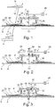
- Fig. 1 shows a sectional view of a system 2 for connecting a first component 4 and a second component 6.
- a molding tool 8 has a tool surface 10 on which the first component 4 is placed.
- the tool surface 10 is continuous, that is to say continuous. However, this could also be modified as long as it is ensured that an arrangement on it is airtight and evacuable.
- the first component 4 is an example of a fuselage shell of a commercial aircraft which has a first cutout 12 at the point shown. This is an example of a window cutout and round, oval or largely square with rounded corners.
- the second component 6 is a window frame later on the inside in the finished aircraft fuselage with a second cutout 14, which is aligned with the first cutout 12.
- the second component 6 also has a flange 16 encircling the second cutout 14, which extends from the second component 6 in a direction facing away from the first component 4.
- the flange 16 follows approximately an edge of the first cutout 12 and can thereby be a section of a lateral surface of a hollow cylinder or a hollow cone.
- the second component 6 has a bearing surface 18 which, for example, lies radially outside the flange 16.
- the contact surface 18 serves to establish a surface contact between the second component 6 and the joining partner.
- This is shown here by way of example in the form of a reinforcing element 20, which is used to thicken an edge surface 21 of the first component 4 that surrounds the first cutout 12.
- the contact surface 18 is consequently glued onto the reinforcing element 20, which is meanwhile glued onto the edge surface 21.
- the reinforcing element 20 can, however, also be omitted if thickening is not required.
- the bearing surface 18 is then glued to the edge surface 21.
- a layer of adhesive is present between the first component 4 and the reinforcing element 20 and between the reinforcing element 20 and the second component 6. This could be designed as a thermosetting adhesive.
- a vacuum film 22 is used to press the components 4 and 6 onto each other, which could be glued to the first component 4 and thereby completely covers the second component 6. After evacuation, the adhesive is pressurized to optimize the quality of the bond. However, since the second component 6 has the second cutout 14, it is not to be expected that a sufficient pressure force can be generated by simply placing the vacuum film 22 on account of the limited contact area.
- an auxiliary body 24 is provided which is placed on the flange 16 and thereby completely covers the second cutout 14.
- the auxiliary body 24 has, for example, a circumferential groove 25 which is adapted to the shape of the flange 16.
- the groove 25 can be placed flush on the flange 16.
- first component 4, second component 6 and auxiliary body 24 is covered by the vacuum film 22. This extends to a termination area 23, which is clearly outside of the second component 6. After evacuation of the space underneath, the entire area determined by an outer contour of the second component 6 acts to generate a compressive force in the direction of the molding tool 8.
- the auxiliary body 24 leads to the introduction of a comparatively large compressive force on the flange 16, so that the radially external adhesive is loaded with a predetermined compressive force and consequently subjected to a desired pressure.
- a vacuum source 26 which is shown schematically as a block, can be coupled to an opening 28 of the vacuum film 22 and suck air from an interior 30 below the vacuum film 22.
- the opening 28 can be aligned with a through hole 32 of the auxiliary body 24. Alternatively, such an opening could also be integrated in the molding tool 8.
- the vacuum film 22 is applied to all of the components located underneath and pushes it towards the tool surface 10. The adhesive is consequently subjected to a desired pressure.
- connection of the two components 4 and 6 can consequently take place outside an autoclave. Larger components in particular can be processed with such a system.
- auxiliary body 24 could be additionally braced.
- An in Fig. 2 shown modified system 34 are used, in which in addition to the components in Fig. 1 a schematically represented actuator 36 is also provided. This acts on the auxiliary body 24.
- the actuator 36 can be a hydraulic or pneumatic actuator and can be supplied with a pressurized fluid. The force exerted by actuator 36 can be adjusted by regulating the pressure applied to actuator 36.
- the actuator 36 can also have a spindle gear, which is coupled to an electric motor. For the sake of simplicity, no fluid lines and no electrical lines are shown which are necessary for operating the actuator 36.
- the actuator 36 is coupled to a force control unit 38, which limits a force exerted on the auxiliary body 24 by the actuator 36.
- a force measuring device can be provided which measures the force exerted on the auxiliary body 24 and controls the actuator 36 as a function thereof.
- a bolt 42 can also be used, which extends into a threaded bore 44 of the molding tool 8 and is guided through a corresponding opening 46 in the auxiliary body 24.
- an additional compressive force acting on the second component 6 can be set become.
- the additional compressive force can particularly preferably be set precisely by using a torque wrench on a screw head 48 of the bolt 42.
- Fig. 4 finally shows a schematic, block-based representation of a method 50 for connecting two components 4 and 6.
- the method 50 has the step of arranging 52 the first component 4 on the tool surface 10.
- the second component 6, which has the cutout 14, is then placed 54 on the first component 4, including an adhesive.
- the auxiliary body 24 covering the second cutout 14 is placed 56 on the second component 6.
- the second component 6, the Auxiliary body 24 and at least one end area of the first component 4 surrounding the second component 6 is covered 58 with the vacuum film 22.
- the space 30 enclosed by the first component 4 and the vacuum film 22 is then evacuated 60.
- the vacuum film 22 is removed 62.
- the auxiliary body can also be braced 64 before covering 58.
- first component 4 and second component 6, in which the adhesive is located can be heated 66.
- Reinforcing element 20 are inserted 68 between the first component 4 and the second component 6, so that reinforcement in particular of an edge area around the first cutout 12 takes place.
Landscapes
- Engineering & Computer Science (AREA)
- Mechanical Engineering (AREA)
- General Engineering & Computer Science (AREA)
- Aviation & Aerospace Engineering (AREA)
- Manufacturing & Machinery (AREA)
- Transportation (AREA)
- Lining Or Joining Of Plastics Or The Like (AREA)
Abstract
Description
- Die Erfindung betrifft ein Verfahren zum Verbinden zweier Bauteile sowie ein System zum Verbinden zweier Bauteile.
- Im modernen Fahrzeugbau kommen unterschiedlichste Verbindungsverfahren zum Verbinden zweier Bauteile zum Einsatz. Die Art einer Verbindung hängt häufig von den verwendeten Materialien, der Größe der zu verbindenden Bauteile, deren Form und der vorgesehenen Belastung ab. Während bei der Verwendung von metallischen Fügepartnern oftmals Schweiß- oder Nietverfahren eingesetzt werden, werden großflächige Bauteile aus Kunststoffen oft geklebt. Werden unterschiedliche Materialien, etwa Kunststoffe und Metalle, eingesetzt, kann auch dort eine Verklebung erfolgen. Zur zusätzlichen Sicherung können Nietverwendungen eingesetzt werden, was jedoch eine aufwändigere Bearbeitung der Fügepartner erfordert.
- Es ist bekannt, zur Herstellung präziser Verklebungen die Fügepartner und den Klebstoff einem Druck auszusetzen. Dadurch können mehrere Vorteile erreicht werden. Bei Polykondensationsklebstoffen können Spaltprodukte und insbesondere Wasser aus der Klebefuge ausgetrieben werden. Lösungsmittelreste können bei Lösungsmittelklebstoffen aus der Klebfuge entfernt werden. Auch kann die Adhäsion zwischen dem Klebstoff und den beiden Fügepartnern und die Benetzung verbessert werden, was zu einer verbesserten Belastbarkeit führt. Der Druck kann beispielsweise in einem Autoklaven aufgebracht werden. Der Klebstoff tritt nicht aus der Klebfuge und die Klebschichtdicke bleibt weitgehend konstant. Je steifer bzw. dicker die miteinander zu verklebenden Bauteile sind, desto höher ist der benötigte Druck, um Maßtoleranzen der Oberflächen in der Klebfuge auszugleichen.
- Die Verwendung eines Autoklaven ist allerdings sehr aufwändig und kostenintensiv, insbesondere bei sehr großen, miteinander zu verbindenden Bauteilen. Es ist eine Aufgabe der Erfindung, ein Verfahren zum Verbinden zweier Bauteile vorzuschlagen, bei dem möglichst einfach ein Druck auf den Klebstoff zwischen zwei Fügepartnern eingebracht werden kann, ohne dass ein Autoklav notwendig ist.
- Die Aufgabe wird gelöst durch ein Verfahren mit den Merkmalen des Anspruchs 1. Vorteilhafte Ausführungsformen und Weiterbildungen sind den Unteransprüchen und der nachfolgenden Beschreibung zu entnehmen.
- Es wird ein Verfahren zum Verbinden zweier Bauteile vorgeschlagen, das Verfahren aufweisend die Schritte des Anordnens eines ersten Bauteils auf einer Werkzeugoberfläche, des Anordnens eines zweiten Bauteils, das einen Ausschnitt aufweist, auf dem ersten Bauteil unter Einschluss eines Klebstoffs, des Auflegens eines den Ausschnitt überdeckenden Hilfskörpers auf das zweite Bauteil, des Überdeckens des zweiten Bauteils, des Hilfskörpers und zumindest eines das zweite Bauteil umgebenden Abschlussbereichs des ersten Bauteils mit einer Vakuumfolie, des Evakuierens des von dem ersten Bauteil und der Vakuumfolie umschlossenen Raums und des Entfernens der Vakuumfolie nach Aushärten des Klebstoffs.
- Das Anordnen eines ersten Bauteils auf einer Werkzeugoberfläche ist dahingehend zu verstehen, dass das erste Bauteil auf die Werkzeugoberfläche gelegt wird, so dass eine darauf befindliche vorgesehene Fügefläche von außen gut erreichbar ist. Die Fügefläche ist dann folglich bevorzugt auf einer von der Werkzeugoberfläche abgewandten Seite angeordnet.
- Die Werkzeugoberfläche muss zudem nicht zwangsläufig durch eine durchgehend geschlossene Fläche gebildet sein, sondern es ist denkbar, dass auch einzelne Stützflächen zum Auflegen des ersten Bauteils vorliegen. Insbesondere größere Bauteile, etwa Rumpfschalen eines Flugzeugs oder dergleichen, könnten auf einem System aus Stützflächen oder Halteelementen angeordnet sein.
- Das zweite Bauteil weist einen Ausschnitt auf, der beispielsweise zum Ausbilden eines Fensterrahmens genutzt wird. Das zweite Bauteil wird so auf das erste Bauteil gelegt, dass die Fügefläche des zweiten Bauteils auf der Fügefläche des ersten Bauteils liegt. Die Fügefläche des zweiten Bauteils kann etwa auf einem Rand um den Ausschnitt herum angeordnet sein.
- Zudem wird der Klebstoff zwischen das erste Bauteil und das zweite Bauteil gebracht. Dies kann dadurch erfolgen, dass der Klebstoff auf die erste Fügefläche aufgebracht wird oder auf die zweite Fügefläche. Es kann auch vorteilhaft sein, auf beide Fügeflächen den Klebstoff aufzubringen. Es ist vorstellbar, dass der Klebstoff über eine Abgabevorrichtung dosiert auf die betreffende Fügefläche aufgebracht wird, beispielsweise geführt durch einen Roboter. Andererseits kann auch bei einer Kleinserienproduktion das manuelle Auftragen des Klebstoffs erfolgen. Es ist zudem denkbar, den Klebstoff als Klebstofffolie einzusetzen, die bei Raumtemperatur fest ist und erst durch Erwärmung flüssig wird und die Bauteile benetzend aushärtet.
- Einen besonderen Vorteil bietet das Auflegen eines den Ausschnitt überdeckenden Hilfskörpers auf das zweite Bauteil. Dieser kann die Abmessungen des Ausschnitts übertreffen und bündig auf das zweite Bauteil aufgelegt werden. Eine Kraft, die auf den Hilfskörper ausgeübt wird, kann durch Berührungsflächen zwischen dem Hilfskörper und dem zweiten Bauteil auf das zweite Bauteil einwirken.
- Liegt der Hilfskörper auf dem zweiten Bauteil auf und überdeckt dieser den Ausschnitt, werden das zweite Bauteil, der Hilfskörper und zumindest eines das zweiten Bauteil umgebenden Abschlussbereichs des ersten Bauteils mit einer Vakuumfolie überdeckt. Damit wird folglich ein abgedichteter Raum unterhalb der Vakuumfolie generiert, der evakuierbar ist. Durch das Evakuieren dieses Raums wirkt folglich der Umgebungsdruck über den Hilfskörper auf das zweite Bauteil, welches folglich den Klebstoff zwischen dem ersten Bauteil und dem zweiten Bauteil mit einer Druckkraft versieht. In diesem Zustand kann der Klebstoff ausgehärtet werden. Nach dem Aushärten wird die Vakuumfolie entfernt.
- Das erfindungsgemäße Verfahren hat den besonderen Vorteil, dass ein Aushärten in einem Autoklaven nicht erforderlich ist, ohne jedoch auf die Beaufschlagung mit einem höheren Druck als durch ein Vakuum alleine erreichbar, d.h. etwa 0,9 bar, zu verzichten. Der höhere Druck zum Herstellen einer gewünschten Verklebung kann durch den aufgebrachten Hilfskörper trotz Ausschnitts des zweiten Bauteils erreicht werden. Damit ist eine deutlich leichtere und kostengünstigere Verklebung der beiden Bauteile miteinander möglich, denn die Verklebung kann lediglich durch ein Vakuum und gegebenenfalls mit einer Erwärmung in einer normalen Fertigungsumgebung außerhalb eines Autoklavs erreicht werden, ohne dass ein Zwischentransport oder eine andere Behandlung der beiden Fügepartner erforderlich ist.
- Das erste Bauteil kann ein Faserverbundwerkstoff oder ein metallischer Werkstoff sein. Das zweite Bauteil kann unabhängig davon ebenso ein Faserverbundwerkstoff oder ein metallischer Werkstoff sein. Etwaige Verstärkungselemente, die weiter nachfolgend erwähnt werden, könnten ebenso unabhängig davon aus einem Faserverbundwerkstoff oder einem metallischen Werkstoff hergestellt sein.
- Bevorzugt weist das Verfahren den Schritt des Erwärmens eines Zwischenraums zwischen dem ersten Bauteil und dem zweiten Bauteil, in dem sich der Klebstoff befindet. Das Erwärmen kann durch Beheizen der Werkzeugoberfläche, das erste Bauteil und/oder das zweite Bauteil erfolgen. Beispielhaft kann die Werkzeugoberfläche erwärmt werden, so dass das darauf befindliche erste Bauteil bzw. der Klebstoff erwärmt werden. Alternativ dazu kann auch das zweite Bauteil durch Auflegen von Heizelementen oder durch Wärmestrahlung erwärmt werden. Es ist denkbar, Heizmatten, einen Ofen, einen Durchlaufofen oder ähnliches einzusetzen. Es ist weiterhin vorstellbar, ein Klebstoffsystem einzusetzen, welches eine Temperatur von 100°C bis 450°C zum Aushärten benötigt. Es sind etwa Klebesysteme zur Verklebung von Faserverbundwerkstoffen bekannt, die bei einer Temperatur von 180°C aushärten. Es sind weiterhin auch andere Klebesysteme bekannt, die bei deutlich niedrigeren Temperaturen aushärten oder zum Aktivieren höheren Temperaturen ausgesetzt werden, etwa bei Faserverbundwerkstoffen mit einer thermoplastischen Matrix.
- In einer vorteilhaften Ausführungsform weist das Verfahren ferner den Schritt des Einbringens eines Verstärkungselements zwischen das erste Bauteil und das zweite Bauteil auf, wobei zwischen dem ersten Bauteil und dem Verstärkungselement und zwischen dem Verstärkungselement und dem zweiten Bauteil Klebstoff eingeschlossen wird. Das Verstärkungselement kann zur Aufdickung eines Bereichs des ersten Bauteils verwendet werden, welches das zweite Bauteil trägt. Da das zweite Bauteil einen Ausschnitt aufweist kann es sinnvoll sein, das Verstärkungselement zum Aufdicken einer umlaufenden Randfläche um den Ausschnitt herum einzusetzen, so dass eine höhere Festigkeit vorliegt.
- In einer vorteilhaften Ausführungsform weist das erste Bauteil einen ersten Ausschnitt auf und das zweite Bauteil weist einen zweiten Ausschnitt auf, wobei das zweite Bauteil derart auf das erste Bauteil aufgelegt wird, dass der erste Ausschnitt und der zweite Ausschnitt in Fluchtung zueinander ausgerichtet werden. Folglich kann die Fügefläche eine Randfläche um den ersten Ausschnitt herum sein, auf das sich ein entsprechender Abschnitt des zweiten Bauteils auflegen lässt. Eine solche Anordnung könnte beispielsweise an einer Rumpfschale eines Verkehrsflugzeugs realisiert sein, wobei der erste Ausschnitt ein Fensterausschnitt ist und das zweite Bauteil einen Fensterrahmen darstellt. Es ist besonders bevorzugt, dass dann das vorangehend genannte Verstärkungselement zwischen die beiden Bauteile eingebracht ist.
- Eine vorteilhafte Ausführungsform kann ferner den Schritt des Verspannens des Hilfskörpers an dem Formwerkzeug mittels eines eine Zugkraft oder eine Druckkraft ausübenden Elements aufweisen. Ist ein Druck in der Klebschicht erforderlich, der durch alleinige Einwirkung des Vakuums auf den Hilfskörper nicht herstellbar ist, kann zur zusätzlichen Unterstützung der Hilfskörper verspannt werden. Die Verspannung kann durch das Ausüben einer Zugkraft in Richtung des Formwerkzeugs erreicht werden oder durch das Aufdrücken mithilfe einer Druckkraft auf eine Seite des Hilfskörpers, die von dem Formwerkzeug abgewandt ist. Je nach erforderlichem Druck kann die zusätzliche, auf den Hilfskörper wirkende Kraft gesteuert werden.
- Es ist vorteilhaft, wenn das Verspannen das Einschrauben eines Bolzens durch eine in dem Hilfskörper angeordnete Öffnung umfasst. Das Formwerkzeug kann für diesen Zweck beispielsweise eine Gewindebohrung aufweisen, in die ein Bolzen einschraubbar ist. Für diesen Zweck sollte auch das erste Bauteil einen Ausschnitt aufweisen, durch den sich der Bolzen in das Formwerkzeug erstrecken kann. Hierdurch kann sehr leicht die zusätzliche, auf den Hilfskörper wirkende Kraft gesteuert werden, indem beispielsweise das Anzugdrehmoment des Bolzens eingestellt wird.
- Allerdings kann das Verspannen auch das Anpressen des Hilfskörpers auf das zweite Bauteil mit einem Aktuator umfassen. Der Aktuator kann auf den Hilfskörper pressen und hierzu eine geeignete Kontaktfläche bereitstellen. Der Aktuator ist auf einer von dem Formwerkzeug abgewandten Seite des Hilfskörpers angeordnet und beispielsweise an einem starren Rahmen gehaltert. Dieser kann starr mit dem Formwerkzeug verbunden sein. Der Aktuator kann ein Hydraulikaktuator oder ein pneumatischer Aktuator sein. Zur präzisen Steuerung der Kraft ist vorstellbar, eine Kraftmesseinheit einzusetzen, welche mit einer Regeleinheit gekoppelt ist, die wiederum den Aktuator ansteuert. Bei der Verwendung insbesondere eines Hydraulikaktuators könnte dies sinnvoll sein, um eine übermäßige Krafteinwirkung zu vermeiden. Selbstverständlich könnten auch Spindelgetriebe oder ähnliche Linearantriebe eingesetzt werden, die nicht auf einem druckbeaufschlagten Fluid basieren. Dort könnte ein Drehmoment überwacht werden, um eine auf den Hilfskörper wirkende Druckkraft zu beschränken.
- Wird ein pneumatische Aktuator eingesetzt, könnte dieser mit einer Vakuumquelle gekoppelt werden, die zum Evakuieren verwendet wird. Hierdurch ergibt sich ein geringerer Konstruktionsaufwand, denn es ist keine separate Druckquelle notwendig, um den Aktuator zu bewegen. Zusätzlich dazu kann auch die entstehende Druckkraft auf den Hilfskörper deutlich beschränkt werden, denn durch die Vakuumquelle könnte ein Druck von höchstens ungefähr 0,95 bar erreicht werden, der auf eine wirksame Fläche des Aktuators wirkt.
- Das zweite Bauteil weist einen mindestens bereichsweise den Ausschnitt umlaufenden Flansch auf, der sich von dem zweiten Bauteil in eine von dem ersten Bauteil abgewandte Richtung erstreckt, wobei der Hilfskörper auf den Flansch aufgelegt wird. Diese Anordnung, welche etwa für einen Fensterrahmen eines Verkehrsflugzeugs realisiert wird, erlaubt eine gute Krafteinleitung von dem Hilfskörper in das zweite Bauteil. Der Hilfskörper könnte eine an den Flansch angepasste, umlaufende Nut aufweisen, welche in Kontakt mit einer Außenkante des Flanschs bringbar ist.
- Die Erfindung betrifft ferner ein System zum Verbinden zweier Bauteile, das System aufweisend ein Formwerkzeug, einen Hilfskörper, eine Vakuumfolie, eine Vakuumquelle, und einen Klebstoff, wobei das Formwerkzeug eine Werkzeugoberfläche zum Aufnehmen eines ersten Bauteils aufweist, wobei der Hilfskörper dazu ausgebildet ist, auf ein zweites Bauteil aufgelegt zu werden und dabei einen Ausschnitt des zweiten Bauteils zu überdecken, wobei die Vakuumfolie dazu ausgebildet ist, das auf das erste Bauteil aufgelegte zweite Bauteil unter Einschluss des Klebstoffs, den auf das zweite Bauteil aufgelegten Hilfskörper und zumindest einen das zweite Bauteil umgebenden Abschlussbereich des ersten Bauteils abzudecken, und wobei die Vakuumquelle mit mindestens einer Öffnung in der Vakuumfolie oder dem Formwerkzeug koppelbar ist, so dass ein von dem ersten Bauteil und der Vakuumfolie umschlossener Raum evakuierbar ist. Es ist vorstellbar, dass das erfindungsgemäße System das vorangehend dargestellte Verfahren ausführen kann.
- Die Werkzeugoberfläche kann eine kontinuierliche, teilweise unterbrochene oder aus lediglich einzelnen Auflageflächen bestehen und dazu ausgebildet sein, dass das erste Bauteil darauf aufgelegt werden kann.
- Der Hilfskörper könnte aus einem ausreichend stabilen Material bestehen, welches für den Einsatzzweck geeignet ist. Da der Hilfskörper lediglich als ein Werkzeug dient, kann dieses eine Platte aus Holz, Holzfasern, einem Kunststoff, Metall oder anderen Materialien bestehen.
- Die Vakuumquelle könnte insbesondere in Form eines Absauggebläses ausgeführt sein. Durch eine Öffnung in der Vakuumfolie kann eine Verbindung zu der Vakuumquelle hergestellt werden, so dass Luft aus dem von der Vakuumfolie umschlossenen Raum abgesaugt wird und folglich der Umgebungsdruck auf die unterhalb der Vakuumfolie liegenden Komponenten einwirkt.
- Bevorzugt weist der Hilfskörper eine gleitfähige Beschichtung auf. Beispielhaft könnte diese Polytetrafluorethylen aufweisen. Damit kann sichergestellt werden, dass die Vakuumfolie auch nach einer Erwärmung leicht von dem Hilfskörper ablösbar ist und der Hilfskörper folglich mehrfach verwendbar ist.
- In einer vorteilhaften Ausführungsform weist die Werkzeugoberfläche eine Gewindebohrung auf, wobei der Hilfskörper eine Öffnung aufweist, die mit der Gewindebohrung bei vorgesehenen Positionen des ersten Bauteils, des zweiten Bauteils und des Hilfskörpers fluchtet, und wobei das System ferner einen Bolzen mit einem mit der Gewindebohrung korrespondierendem Gewinde zum Verspannen des Hilfskörpers an dem Formwerkzeug aufweist.
- Wie vorangehend ausgeführt kann das System ferner einen Aktuator zum Pressen des Hilfskörpers auf das zweite Bauteil aufweisen. Wie ebenso dargelegt, kann der Aktuator ein pneumatischer Aktuator, ein hydraulischer Aktuator oder ein Linearantrieb sein. Es könnte sich anbieten, bei der Verwendung eines pneumatischen Aktuators eine Kopplung mit der Vakuumquelle durchzuführen, so dass die Komplexität des Systems gesenkt werden kann.
- Das System kann zudem ferner eine mit dem Aktuator gekoppelte Kraftregeleinheit aufweisen, die dazu ausgebildet ist, die von dem Aktuator auf den Hilfskörper einwirkende Kraft zu erfassen und auf einen vorbestimmten Wert einzustellen. Durch die Kraftregeleinheit kann die auf den Hilfskörper wirkende Kraft begrenzt werden, so dass die auf die Klebschicht wirkende Druckkraft exakt eingestellt ist.
- Weitere Merkmale, Vorteile und Anwendungsmöglichkeiten der vorliegenden Erfindung ergeben sich aus der nachfolgenden Beschreibung der Ausführungsbeispiele und den Figuren. Dabei bilden alle beschriebenen und/oder bildlich dargestellten Merkmale für sich und in beliebiger Kombination den Gegenstand der Erfindung auch unabhängig von ihrer Zusammensetzung in den einzelnen Ansprüchen oder deren Rückbezügen. In den Figuren stehen weiterhin gleiche Bezugszeichen für gleiche oder ähnliche Objekte.
-
Fig. 1 zeigt eine Schnittdarstellung eines erfindungsgemäßen Systems zum Verbinden von Bauteilen. -
Fig. 2 zeigt eine Schnittdarstellung eines modifizierten Systems zum Verbinden von Bauteilen. -
Fig. 3 zeigt eine Schnittdarstellung eines weiteren, modifizierten Systems zum Verbinden von Bauteilen. -
Fig. 4 zeigt eine schematische, blockbasierte Darstellung eines Verfahrens zum Verbinden von Bauteilen. -
Fig. 1 zeigt eine Schnittdarstellung eines Systems 2 zum Verbinden eines ersten Bauteils 4 und eines zweiten Bauteils 6. Ein Formwerkzeug 8 weist eine Werkzeugoberfläche 10 auf, auf die das erste Bauteil 4 aufgelegt ist. In dieser Darstellung ist die Werkzeugoberfläche 10 durchgehend, d.h. kontinuierlich, ausgeführt. Dies könnte jedoch auch abgewandelt werden, solange sichergestellt wird, dass eine darauf befindliche Anordnung luftdicht und evakuierbar ist. - Das erste Bauteil 4 ist beispielhaft eine Rumpfschale eines Verkehrsflugzeugs, die an der gezeigten Stelle einen ersten Ausschnitt 12 aufweist. Dieser ist beispielhaft ein Fensterausschnitt und rund, oval oder weitgehend viereckig mit abgerundeten Ecken. Das zweite Bauteil 6 ist ein später im fertiggestellten Flugzeugrumpf innenliegender Fensterrahmen mit einem zweiten Ausschnitt 14, der mit dem ersten Ausschnitt 12 fluchtet.
- Das zweite Bauteil 6 weist zudem einen den zweiten Ausschnitt 14 umlaufenden Flansch 16 auf, der sich von dem zweiten Bauteil 6 in eine von dem ersten Bauteil 4 abgewandte Richtung erstreckt. Der Flansch 16 folgt etwa einer Kante des ersten Ausschnitts 12 und kann dadurch ein Abschnitt einer Mantelfläche eines Hohlzylinders oder eines Hohlkegels sein.
- Zum Verbinden des ersten Bauteils 4 und des zweiten Bauteils 6 weist das zweite Bauteil 6 eine Auflagefläche 18, die beispielhaft radial außerhalb des Flanschs 16 liegt. Die Auflagefläche 18 dient zur Herstellung eines Flächenkontakts zwischen dem zweiten Bauteil 6 und dem Fügepartner. Dieser ist hier beispielhaft in Form eines Verstärkungselements 20 dargestellt, welches zur Aufdickung einer den ersten Ausschnitt 12 umlaufenden Randfläche 21 des ersten Bauteils 4 eingesetzt wird. Die Auflagefläche 18 wird folglich auf das Verstärkungselement 20 geklebt, welches indes auf die Randfläche 21 geklebt wird. Das Verstärkungselement 20 kann jedoch auch weggelassen werden, wenn eine Aufdickung nicht erforderlich ist. Die Auflagefläche 18 wird dann folglich auf die Randfläche 21 geklebt.
- In dem gezeigten Beispiel ist zwischen dem ersten Bauteil 4 und dem Verstärkungselement 20 sowie zwischen dem Verstärkungselement 20 und dem zweiten Bauteil 6 jeweils eine Schicht Klebstoff vorhanden. Dieser könnte als wärmehärtbarer Klebstoff ausgeführt sein.
- Zum Anpressen der Bauteile 4 und 6 aufeinander wird eine Vakuumfolie 22 eingesetzt, die auf das erste Bauteil 4 aufgeklebt sein könnte und dabei das zweite Bauteil 6 vollständig überdeckt. Der Klebstoff wird nach Evakuierung mit einem Druck beaufschlagt, um die Qualität der Verklebung zu optimieren. Da allerdings das zweite Bauteil 6 den zweiten Ausschnitt 14 aufweist, ist durch ein reines Auflegen der Vakuumfolie 22 aufgrund der begrenzten Auflagefläche nicht damit zu rechnen, dass eine ausreichende Druckkraft hervorgerufen werden kann.
- Um diese zu steigern, ist ein Hilfskörper 24 vorgesehen, der auf den Flansch 16 aufgelegt wird und dabei den zweiten Ausschnitt 14 vollständig überdeckt. Der Hilfskörper 24 weist beispielhaft eine umlaufende Nut 25 auf, die an die Form des Flanschs 16 angepasst ist. Die Nut 25 kann bündig auf den Flansch 16 aufgelegt werden.
- Die vollständige Anordnung aus Formwerkzeug 8, erstem Bauteil 4, zweitem Bauteil 6 und Hilfskörper 24 wird durch die Vakuumfolie 22 abgedeckt. Diese erstreckt sich bis zu einem Abschlussbereich 23, der deutlich außerhalb des zweite Bauteils 6 liegt. Nach Evakuierung des darunterliegenden Raums wirkt die gesamte, durch eine Außenkontur des zweiten Bauteils 6 bestimmte Fläche zur Entstehung einer Druckkraft in Richtung des Formwerkzeugs 8. Der Hilfskörper 24 führt zur Einleitung einer vergleichsweise großen Druckkraft auf den Flansch 16, so dass der radial außerhalb liegende Klebstoff mit einer vorbestimmten Druckkraft belastet und folglich einem gewünschten Druck ausgesetzt wird.
- Eine Vakuumquelle 26, welche schematisch als Block dargestellt ist, kann mit einer Öffnung 28 der Vakuumfolie 22 gekoppelt sein und Luft aus einem Innenraum 30 unterhalb der Vakuumfolie 22 absaugen. Die Öffnung 28 kann mit einer Durchgangsbohrung 32 des Hilfskörpers 24 in Fluchtung sein. Alternativ könnte eine solche Öffnung auch in dem Formwerkzeug 8 integriert sein. Durch das Evakuieren legt sich die Vakuumfolie 22 auf sämtliche darunter befindlichen Komponenten an und drückt diese in Richtung der Werkzeugoberfläche 10. Der Klebstoff wird folglich einem gewünschten Druck ausgesetzt.
- Die Verbindung der beiden Bauteile 4 und 6 kann folglich außerhalb eines Autoklaven erfolgen. Insbesondere größere Bauteile können mit einem solchen System bearbeitet werden.
- Sollte jedoch der durch das System 2 erzielte Druck noch nicht ausreichen, könnte der Hilfskörper 24 zusätzlich verspannt werden. Hierzu könnte ein in
Fig. 2 gezeigtes modifiziertes System 34 eingesetzt werden, in dem zusätzlich zu den Komponenten inFig. 1 auch ein schematisch dargestellter Aktuator 36 vorgesehen ist. Dieser wirkt auf den Hilfskörper 24 ein. Der Aktuator 36 kann ein Hydraulik- oder Pneumatikaktuator sein und mit einem druckbeaufschlagten Fluid versorgt werden. Die von dem Aktuator 36 ausgeübte Kraft kann durch Regelung des an den Aktuator 36 angelegten Drucks justiert werden. Alternativ dazu kann der Aktuator 36 auch ein Spindelgetriebe aufweisen, das mit einem Elektromotor gekoppelt ist. Der Einfachheit halber sind keine Fluidleitungen und keine elektrischen Leitungen dargestellt, die zum Betreiben des Aktuators 36 notwendig sind. - Es ist außerdem vorstellbar, dass der Aktuator 36 mit einer Kraftregeleinheit 38 gekoppelt ist, die eine auf dem Hilfskörper 24 durch den Aktuator 36 ausgeübte Kraft begrenzt. Hierzu kann eine Kraftmesseinrichtung vorgesehen sein, welche die auf den Hilfskörper 24 ausgeübte Kraft misst und in Abhängigkeit davon den Aktuator 36 ansteuert.
- Wie in
Fig. 3 anhand eines weiteren modifizierten Systems 40 kann auch ein Bolzen 42 eingesetzt werden, der sich in eine Gewindebohrung 44 des Formwerkzeugs 8 erstreckt und durch eine entsprechende Öffnung 46 des Hilfskörpers 24 geführt ist. Durch Einschrauben des Bolzens 42 durch die Öffnung 46 in die Gewindebohrung 44 kann eine zusätzliche, auf das zweite Bauteil 6 einwirkende Druckkraft eingestellt werden. Besonders bevorzugt kann die zusätzliche Druckkraft durch Verwendung eines Drehmomentschlüssels an einem Schraubkopf 48 des Bolzens 42 präzise eingestellt werden. -
Fig. 4 zeigt schließlich eine schematische, blockbasierte Darstellung eine Verfahrens 50 zum Verbinden zweier Bauteile 4 und 6. Das Verfahren 50 weist den Schritt des Anordnens 52 des ersten Bauteils 4 auf der Werkzeugoberfläche 10 auf. Anschließend wird das zweite Bauteil 6, das den Ausschnitt 14 aufweist, auf dem ersten Bauteil 4 unter Einschluss eines Klebstoffs gelegt 54. Der den zweiten Ausschnitt 14 überdeckende Hilfskörper 24 wird auf das zweite Bauteil 6 gelegt 56. Weiterhin werden das zweite Bauteil 6, der Hilfskörper 24 und zumindest eines das zweite Bauteil 6 umgebenden Abschlussbereichs des ersten Bauteils 4 mit der Vakuumfolie 22 überdeckt 58. Der von dem ersten Bauteil 4 und der Vakuumfolie 22 umschlossene Raum 30 wird anschließend evakuiert 60. Nach dem Aushärten des Klebstoffs wird die Vakuumfolie 22 entfernt 62. Optional kann der Hilfskörper vor dem Überdecken 58 auch verspannt werden 64. Des Weiteren kann nach dem Überdecken 58 ein Zwischenraum zwischen dem ersten Bauteil 4 und dem zweiten Bauteil 6, in dem sich der Klebstoff befindet, erwärmt werden 66. Ebenfalls optional kann das Verstärkungselement 20 zwischen das erste Bauteil 4 und das zweite Bauteil 6 eingebracht werden 68, so dass eine Verstärkung insbesondere eines Randbereichs um den ersten Ausschnitt 12 erfolgt. - Ergänzend sei darauf hingewiesen, dass "aufweisend" keine anderen Elemente oder Schritte ausschließt, und "ein" oder "eine" keine Vielzahl ausschließt. Ferner sei daraufhingewiesen, dass Merkmale, die mit Verweis auf eines der obigen Ausführungsbeispiele beschrieben worden sind, auch in Kombination mit anderen Merkmalen anderer oben beschriebener Ausführungsbeispiele verwendet werden können. Bezugszeichen in den Ansprüchen sind nicht als Einschränkung anzusehen.
-
- 2
- System
- 4
- erstes Bauteil
- 6
- zweites Bauteil
- 8
- Formwerkzeug
- 10
- Werkzeugoberfläche
- 12
- erster Ausschnitt
- 14
- zweiter Ausschnitt
- 16
- Flansch
- 18
- Auflagefläche
- 20
- Verstärkungselement
- 21
- Randfläche
- 22
- Vakuumfolie
- 23
- Abschlussbereich
- 24
- Hilfskörper
- 25
- Nut
- 26
- Vakuumquelle
- 28
- Öffnung
- 30
- Innenraum
- 32
- Durchgangsbohrung
- 34
- System
- 36
- Aktuator
- 38
- Kraftregeleinheit
- 40
- System
- 42
- Bolzen
- 44
- Gewindebohrung
- 46
- Öffnung
- 48
- Schraubkopf
- 50
- Verfahren
- 52
- Anordnen des ersten Bauteils
- 54
- Anordnen des zweiten Bauteils
- 56
- Auflegen des Hilfskörpers
- 58
- Überdecken mit Vakuumfolie
- 60
- Evakuieren
- 62
- Entfernen der Vakuumfolie
- 64
- Verspannen des Hilfskörpers
- 66
- Erwärmen
- 68
- Einbringen des Verstärkungselements
Claims (14)
- Verfahren (50) zum Verbinden zweier Bauteile, aufweisend die Schritte:- Anordnen (52) eines ersten Bauteils (4) auf einer Werkzeugoberfläche (10),- Anordnen (54) eines zweiten Bauteils (6), das einen Ausschnitt (14) aufweist, auf dem ersten Bauteil (4) unter Einschluss eines Klebstoffs,- Auflegen (56) eines den Ausschnitt (14) überdeckenden Hilfskörpers (24) auf das zweite Bauteil (6),- Überdecken (58) des zweiten Bauteils (6), des Hilfskörpers (24) und zumindest eines das zweite Bauteil (6) umgebenden Abschlussbereichs (23) des ersten Bauteils (4) mit einer Vakuumfolie (22),- Evakuieren (60) des von dem ersten Bauteil (4) und der Vakuumfolie (22) umschlossenen Raums (30) und- Entfernen der Vakuumfolie (22) nach Aushärten des Klebstoffs.
- Verfahren (50) nach Anspruch 1,
ferner aufweisend den Schritt des Erwärmens (66) eines Zwischenraums zwischen dem ersten Bauteil (4) und dem zweiten Bauteil (6), in dem sich der Klebstoff befindet. - Verfahren (50) nach Anspruch 1 oder 2,
ferner aufweisend den Schritt des Einbringens (68) eines Verstärkungselements (20) zwischen das erste Bauteil (4) und das zweite Bauteil (6), wobei zwischen dem ersten Bauteil (4) und dem Verstärkungselement (20) und zwischen dem Verstärkungselement (20) und dem zweiten Bauteil (6) Klebstoff eingeschlossen wird. - Verfahren (50) nach einem der vorhergehenden Ansprüche,
wobei das erste Bauteil (4) einen ersten Ausschnitt (12) aufweist, wobei das zweite Bauteil (6) einen zweiten Ausschnitt (14) aufweist und wobei das zweite Bauteil (6) derart auf das erste Bauteil (4) aufgelegt wird, dass der erste Ausschnitt (12) und der zweite Ausschnitt (14) in Fluchtung zueinander ausgerichtet werden. - Verfahren (50) nach einem der vorhergehenden Ansprüche,
ferner aufweisend den Schritt des Verspannens (64) des Hilfskörpers (24) an dem Formwerkzeug (8) mittels eines eine Zugkraft oder eine Druckkraft ausübenden Elements. - Verfahren (50) nach Anspruch 5,
wobei das Verspannen (64) das Einschrauben eines Bolzens (42) durch eine in dem Hilfskörper (24) angeordnete Öffnung (46) umfasst. - Verfahren (50) nach einem der vorhergehenden Ansprüche,
wobei das Verspannen (64) das Anpressen des Hilfskörpers (24) auf das zweite Bauteil (6) mit einem Aktuator (36) umfasst. - Verfahren (50) nach Anspruch 7,
wobei der Aktuator (36) mit einer Vakuumquelle (26) gekoppelt wird, die zum Evakuieren (60) verwendet wird. - Verfahren (50) nach einem der vorhergehenden Ansprüche,
wobei das zweite Bauteil (6) einen mindestens bereichsweise den Ausschnitt (14) umlaufenden Flansch (16) aufweist, der sich von dem zweiten Bauteil (6) in eine von dem ersten Bauteil (4) abgewandte Richtung erstreckt, wobei der Hilfskörper (24) auf den Flansch (16) aufgelegt wird. - System (2, 34, 40) zum Verbinden zweier Bauteile, aufweisend:- ein Formwerkzeug (8),- einen Hilfskörper (24),- eine Vakuumfolie (22),- eine Vakuumquelle (26), und- einen Klebstoff,wobei das Formwerkzeug (8) eine Werkzeugoberfläche (10) zum Aufnehmen eines ersten Bauteils (4) aufweist,
wobei der Hilfskörper (24) dazu ausgebildet ist, auf ein zweites Bauteil (6) aufgelegt zu werden und dabei einen Ausschnitt (14) des zweiten Bauteils (6) zu überdecken,
wobei die Vakuumfolie (22) dazu ausgebildet ist, das auf das erste Bauteil (4) aufgelegte zweite Bauteil (6) unter Einschluss des Klebstoffs, den auf das zweite Bauteil (6) aufgelegten Hilfskörper (24) und zumindest einen das zweite Bauteil (6) umgebenden Abschlussbereich des ersten Bauteils (4) abzudecken, und
wobei die Vakuumquelle (26) mit mindestens einer Öffnung (28) in der Vakuumfolie (22) oder dem Formwerkzeug (8) koppelbar ist, so dass ein von dem ersten Bauteil (4) und der Vakuumfolie (22) umschlossener Raum evakuierbar ist. - System (2, 34, 40) nach Anspruch 10,
wobei der Hilfskörper (24) eine gleitfähige Beschichtung aufweist. - System (2, 34, 40) nach Anspruch 10 oder 11,
wobei die Werkzeugoberfläche (10) eine Gewindebohrung (44) aufweist,
wobei der Hilfskörper (24) eine Öffnung (46) aufweist, die mit der Gewindebohrung (44) bei vorgesehenen Positionen des ersten Bauteils (4), des zweiten Bauteils (6) und des Hilfskörpers (24) fluchtet, und
wobei das System (2, 34, 40) ferner einen Bolzen (42) mit einem mit der Gewindebohrung (44) korrespondierendem Gewinde zum Verspannen des Hilfskörpers (24) an dem Formwerkzeug (8) aufweist. - System (2, 34, 40) nach einem der Ansprüche 10 bis 12,
ferner aufweisend einen Aktuator (36) zum Pressen des Hilfskörpers (24) auf das zweite Bauteil (6). - System (2, 34, 40) nach Anspruch 13,
ferner aufweisend eine mit dem Aktuator (36) gekoppelte Kraftregeleinheit (38), die dazu ausgebildet ist, die von dem Aktuator (36) auf den Hilfskörper (24) einwirkende Kraft zu erfassen und auf einen vorbestimmten Wert einzustellen.
Applications Claiming Priority (1)
| Application Number | Priority Date | Filing Date | Title |
|---|---|---|---|
| DE102018125979.4A DE102018125979A1 (de) | 2018-10-19 | 2018-10-19 | Verfahren und System zum Verbinden zweier Bauteile |
Publications (2)
| Publication Number | Publication Date |
|---|---|
| EP3640485A1 true EP3640485A1 (de) | 2020-04-22 |
| EP3640485B1 EP3640485B1 (de) | 2021-06-30 |
Family
ID=68296062
Family Applications (1)
| Application Number | Title | Priority Date | Filing Date |
|---|---|---|---|
| EP19203994.9A Active EP3640485B1 (de) | 2018-10-19 | 2019-10-18 | Verfahren und system zum verbinden zweier bauteile |
Country Status (4)
| Country | Link |
|---|---|
| US (1) | US11787125B2 (de) |
| EP (1) | EP3640485B1 (de) |
| CN (1) | CN111075810A (de) |
| DE (1) | DE102018125979A1 (de) |
Cited By (1)
| Publication number | Priority date | Publication date | Assignee | Title |
|---|---|---|---|---|
| IT202000027287A1 (it) * | 2020-11-13 | 2022-05-13 | Leonardo Spa | Metodo e attrezzatura per l'integrazione di longheroni continui aventi sezione a j in pannelli allungati di materiale composito |
Families Citing this family (1)
| Publication number | Priority date | Publication date | Assignee | Title |
|---|---|---|---|---|
| DE102023114402A1 (de) * | 2023-06-01 | 2024-12-05 | Premium Aerotec Gmbh | Verfahren zum Verbinden eines Fensterrahmens mit einer Rumpfhaut eines Luftfahrzeugs aus einem Faserverbundwerkstoff |
Citations (13)
| Publication number | Priority date | Publication date | Assignee | Title |
|---|---|---|---|---|
| US3950204A (en) * | 1972-09-29 | 1976-04-13 | Texas Instruments Incorporated | Low pressure, thin film bonding |
| US4927480A (en) * | 1989-02-27 | 1990-05-22 | Signet Armorlite, Inc. | Method and clamping device for bonding thin lens wafers |
| US6083604A (en) * | 1994-10-26 | 2000-07-04 | Mitsubishi Denki Kabushiki Kaisha | Bonded assembly, method of jointing for preparation thereof and rivet |
| EP1484164A2 (de) * | 2003-06-06 | 2004-12-08 | EADS Deutschland GmbH | Verfahren zum Verkleben von Bauteilen und insbesondere von Faserverbundbauteilen |
| DE102006007429A1 (de) * | 2006-02-17 | 2007-08-30 | Airbus Deutschland Gmbh | Verfahren zum autoklavfreien Verkleben von Bauteilen für Luftfahrzeuge |
| US20080099131A1 (en) * | 2006-10-31 | 2008-05-01 | Jamco Corporation | Method for continuously forming structural member |
| WO2010122325A1 (en) * | 2009-04-23 | 2010-10-28 | Airbus Operations Limited | Composite structure |
| JP2010260174A (ja) * | 2009-04-28 | 2010-11-18 | Taisei Plas Co Ltd | 金属合金と繊維強化プラスチックの複合体の製造方法 |
| WO2015064182A1 (en) * | 2013-10-30 | 2015-05-07 | Toyota Jidosha Kabushiki Kaisha | Fastening structure |
| US20150285290A1 (en) * | 2012-12-19 | 2015-10-08 | Bayerische Motoren Werke Aktiengesellschaft | Fastening Device for Fastening a Structural Part Consisting of a Carbon-Fiber-Reinforced Plastic to a Component, in Particular a Chassis Component of a Vehicle |
| US9713901B2 (en) * | 2015-05-27 | 2017-07-25 | The Boeing Company | Method to reduce residual stress in an integrally-stiffened co-bonded structure |
| EP3249242A1 (de) * | 2015-01-22 | 2017-11-29 | Nissan Motor Co., Ltd. | Befestigungsstruktur für kohlenstofffaserverstärktes harzmaterial |
| US20180178460A1 (en) * | 2016-12-23 | 2018-06-28 | Airbus Group Limited | Joining Method and Apparatus |
Family Cites Families (13)
| Publication number | Priority date | Publication date | Assignee | Title |
|---|---|---|---|---|
| JPH10146898A (ja) * | 1996-11-15 | 1998-06-02 | Honda Motor Co Ltd | 繊維強化複合材の成形方法 |
| US6692681B1 (en) * | 1997-01-29 | 2004-02-17 | Raytheon Aircraft Company | Method and apparatus for manufacturing composite structures |
| US8262823B2 (en) * | 2003-09-04 | 2012-09-11 | The Boeing Company | Window skin panel and method of making same |
| US7186367B2 (en) * | 2004-05-13 | 2007-03-06 | The United States Of America As Represented By The Administrator Of The National Aeronautics And Space Administration | Double vacuum bag process for resin matrix composite manufacturing |
| US7670527B2 (en) * | 2006-05-09 | 2010-03-02 | Lockheed Martin Corporation | Failsafe injected adhesive joint |
| US8303882B2 (en) * | 2009-02-23 | 2012-11-06 | General Electric Company | Apparatus and method of making composite material articles |
| DE102010006328A1 (de) * | 2010-01-29 | 2011-08-04 | Premium AEROTEC GmbH, 86179 | Verfahren zur Herstellung einer Klebeverbindung und Klebeverbindung sowie Anordnung zur Durchführung des Verfahrens |
| US8262841B2 (en) * | 2010-11-24 | 2012-09-11 | The Boeing Company | Methods for void-free debulking of adhesive bonded joints |
| CN103261021B (zh) * | 2010-12-28 | 2016-01-20 | 贝尔直升机泰克斯特龙公司 | 多向负载连接系统 |
| US8961732B2 (en) * | 2011-01-03 | 2015-02-24 | The Boeing Company | Method and device for compressing a composite radius |
| US9707705B2 (en) * | 2013-07-02 | 2017-07-18 | The Boeing Company | Vacuum bag processing of composite parts using a conformable vacuum bag assembly |
| US10369756B2 (en) * | 2015-08-25 | 2019-08-06 | The Boeing Company | Method of manufacturing a composite article |
| US10195819B1 (en) * | 2016-02-02 | 2019-02-05 | Fred D Donnelly | Multilayer ceramic composite and method of production |
-
2018
- 2018-10-19 DE DE102018125979.4A patent/DE102018125979A1/de not_active Ceased
-
2019
- 2019-10-14 CN CN201910972908.1A patent/CN111075810A/zh active Pending
- 2019-10-17 US US16/655,368 patent/US11787125B2/en active Active
- 2019-10-18 EP EP19203994.9A patent/EP3640485B1/de active Active
Patent Citations (13)
| Publication number | Priority date | Publication date | Assignee | Title |
|---|---|---|---|---|
| US3950204A (en) * | 1972-09-29 | 1976-04-13 | Texas Instruments Incorporated | Low pressure, thin film bonding |
| US4927480A (en) * | 1989-02-27 | 1990-05-22 | Signet Armorlite, Inc. | Method and clamping device for bonding thin lens wafers |
| US6083604A (en) * | 1994-10-26 | 2000-07-04 | Mitsubishi Denki Kabushiki Kaisha | Bonded assembly, method of jointing for preparation thereof and rivet |
| EP1484164A2 (de) * | 2003-06-06 | 2004-12-08 | EADS Deutschland GmbH | Verfahren zum Verkleben von Bauteilen und insbesondere von Faserverbundbauteilen |
| DE102006007429A1 (de) * | 2006-02-17 | 2007-08-30 | Airbus Deutschland Gmbh | Verfahren zum autoklavfreien Verkleben von Bauteilen für Luftfahrzeuge |
| US20080099131A1 (en) * | 2006-10-31 | 2008-05-01 | Jamco Corporation | Method for continuously forming structural member |
| WO2010122325A1 (en) * | 2009-04-23 | 2010-10-28 | Airbus Operations Limited | Composite structure |
| JP2010260174A (ja) * | 2009-04-28 | 2010-11-18 | Taisei Plas Co Ltd | 金属合金と繊維強化プラスチックの複合体の製造方法 |
| US20150285290A1 (en) * | 2012-12-19 | 2015-10-08 | Bayerische Motoren Werke Aktiengesellschaft | Fastening Device for Fastening a Structural Part Consisting of a Carbon-Fiber-Reinforced Plastic to a Component, in Particular a Chassis Component of a Vehicle |
| WO2015064182A1 (en) * | 2013-10-30 | 2015-05-07 | Toyota Jidosha Kabushiki Kaisha | Fastening structure |
| EP3249242A1 (de) * | 2015-01-22 | 2017-11-29 | Nissan Motor Co., Ltd. | Befestigungsstruktur für kohlenstofffaserverstärktes harzmaterial |
| US9713901B2 (en) * | 2015-05-27 | 2017-07-25 | The Boeing Company | Method to reduce residual stress in an integrally-stiffened co-bonded structure |
| US20180178460A1 (en) * | 2016-12-23 | 2018-06-28 | Airbus Group Limited | Joining Method and Apparatus |
Cited By (3)
| Publication number | Priority date | Publication date | Assignee | Title |
|---|---|---|---|---|
| IT202000027287A1 (it) * | 2020-11-13 | 2022-05-13 | Leonardo Spa | Metodo e attrezzatura per l'integrazione di longheroni continui aventi sezione a j in pannelli allungati di materiale composito |
| WO2022101848A1 (en) * | 2020-11-13 | 2022-05-19 | Leonardo S.P.A. | Method and equipment for the integration of continuous j shaped spars in extended panels of composite material |
| US12337548B2 (en) | 2020-11-13 | 2025-06-24 | Leonardo S.P.A. | Method and equipment for the integration of continuous J shaped spars in extended panels of composite material |
Also Published As
| Publication number | Publication date |
|---|---|
| US11787125B2 (en) | 2023-10-17 |
| DE102018125979A1 (de) | 2020-04-23 |
| EP3640485B1 (de) | 2021-06-30 |
| US20200122411A1 (en) | 2020-04-23 |
| CN111075810A (zh) | 2020-04-28 |
Similar Documents
| Publication | Publication Date | Title |
|---|---|---|
| DE102008001498B3 (de) | Verfahren und Umformvorrichtung zur Herstellung eines Faserverbundbauteils für die Luft- und Raumfahrt | |
| DE102017112881B4 (de) | Verfahren zum Verbinden von unterschiedlichen Materialwerkstücken | |
| EP2481569B1 (de) | Kraftfahrzeugbauteil und Verfahren zur Herstellung des Kraftfahrzeugbauteils | |
| EP3105038B1 (de) | Verfahren zur herstellung eines verbundbauteils | |
| DE102010050740B4 (de) | Verfahren und Vorrichtung zur Herstellung eines Flugzeugstrukturbauteils | |
| DE102006007429B4 (de) | Verfahren zum autoklavfreien Verkleben von Bauteilen für Luftfahrzeuge | |
| DE102007062872A1 (de) | Verfahren zur Herstellung eines Profils aus Faserverbundwerkstoff | |
| DE102016210124B4 (de) | Verfahren zur Integration einer Hinterbaustruktur-Baugruppe in eine Struktur eines Luft- oder Raumfahrzeugs | |
| EP2185339A1 (de) | Verfahren zur herstellung eines bauteils sowie faserverstärktes thermoplastisches bauteil | |
| EP3269532B1 (de) | Verfahren zum fügen zweier faserverbund-fügepartner | |
| EP3640485B1 (de) | Verfahren und system zum verbinden zweier bauteile | |
| DE102015206534B4 (de) | Verbindungsanordnung sowie Verfahren zur Herstellung einer solchen Verbindungsanordnung | |
| DE102010045210B4 (de) | Vakuumaufbau zur Druckbeaufschlagung eines Bauteils während seiner Herstellung, und Verfahren zur Herstellung eines Bauteils | |
| EP3524414A1 (de) | Unterdruckbeaufschlagbarer stempel aus schaumkunststoff | |
| DE102014206375B4 (de) | Reibschweiß-Vorrichtung zum Fügen von Bauteilen, von denen wenigstens eines aus einem faserverstärkten Kunststoff gebildet ist | |
| EP3527641B1 (de) | Klebefilm sowie anordnung und verfahren zur überprüfung einer klebeanbindung | |
| DE102014001690B4 (de) | Verfahren zum Fügen eines Metallbauteils mit einem Kunststoffbauteil | |
| DE102005057891A1 (de) | Verfahren und Vorrichtung zum Verbinden eines Kunstoff-Werkstücks mit einem weiteren Werkstück | |
| DE102012015183A1 (de) | Fügeverbindung zwischen zwei Bauteilen, Blindniet für eine solche Fügeverbindung sowie Verfahren zur Herstellung einer solchen Fügeverbindung | |
| DE102010048118B4 (de) | Verfahren zur Herstellung eines Hybridbauteils und Kraftfahrzeughybridbauteil | |
| DE102006001494B3 (de) | Verfahren und Vorrichtung zum Herstellen einer Fügung von Bauteilen | |
| DE102006038666A1 (de) | Herstellungsverfahren für ein Werkstück aus einem Faserverbundwerkstoff | |
| DE102014012562B3 (de) | Verfahren zum Herstellen einer Fügestelle an einem Bauteil aus einem Faserverbundwerkstoff | |
| DE102015115788B4 (de) | Umgeschlagene Struktur und Verfahren zum Umschlagen | |
| DE102013013001B3 (de) | Verfahren zum Herstellen einer Falz- und Klebeverbindung zwischen Blechbauteilen sowie Bauteilverbund |
Legal Events
| Date | Code | Title | Description |
|---|---|---|---|
| PUAI | Public reference made under article 153(3) epc to a published international application that has entered the european phase |
Free format text: ORIGINAL CODE: 0009012 |
|
| STAA | Information on the status of an ep patent application or granted ep patent |
Free format text: STATUS: THE APPLICATION HAS BEEN PUBLISHED |
|
| AK | Designated contracting states |
Kind code of ref document: A1 Designated state(s): AL AT BE BG CH CY CZ DE DK EE ES FI FR GB GR HR HU IE IS IT LI LT LU LV MC MK MT NL NO PL PT RO RS SE SI SK SM TR |
|
| AX | Request for extension of the european patent |
Extension state: BA ME |
|
| STAA | Information on the status of an ep patent application or granted ep patent |
Free format text: STATUS: REQUEST FOR EXAMINATION WAS MADE |
|
| 17P | Request for examination filed |
Effective date: 20201022 |
|
| RBV | Designated contracting states (corrected) |
Designated state(s): AL AT BE BG CH CY CZ DE DK EE ES FI FR GB GR HR HU IE IS IT LI LT LU LV MC MK MT NL NO PL PT RO RS SE SI SK SM TR |
|
| REG | Reference to a national code |
Ref country code: DE Ref legal event code: R079 Ref document number: 502019001721 Country of ref document: DE Free format text: PREVIOUS MAIN CLASS: F16B0011000000 Ipc: B64C0001140000 |
|
| RIC1 | Information provided on ipc code assigned before grant |
Ipc: B64C 1/14 20060101AFI20210305BHEP Ipc: B64F 5/10 20170101ALI20210305BHEP Ipc: F16B 11/00 20060101ALI20210305BHEP Ipc: B29C 65/00 20060101ALI20210305BHEP Ipc: B29C 65/48 20060101ALI20210305BHEP Ipc: B29L 12/00 20060101ALN20210305BHEP Ipc: B29L 31/30 20060101ALN20210305BHEP Ipc: B29L 31/00 20060101ALN20210305BHEP |
|
| GRAP | Despatch of communication of intention to grant a patent |
Free format text: ORIGINAL CODE: EPIDOSNIGR1 |
|
| STAA | Information on the status of an ep patent application or granted ep patent |
Free format text: STATUS: GRANT OF PATENT IS INTENDED |
|
| RIC1 | Information provided on ipc code assigned before grant |
Ipc: B64C 1/14 20060101AFI20210319BHEP Ipc: B64F 5/10 20170101ALI20210319BHEP Ipc: F16B 11/00 20060101ALI20210319BHEP Ipc: B29C 65/00 20060101ALI20210319BHEP Ipc: B29C 65/48 20060101ALI20210319BHEP Ipc: B29L 12/00 20060101ALN20210319BHEP Ipc: B29L 31/30 20060101ALN20210319BHEP Ipc: B29L 31/00 20060101ALN20210319BHEP |
|
| RIC1 | Information provided on ipc code assigned before grant |
Ipc: B64C 1/14 20060101AFI20210326BHEP Ipc: B64F 5/10 20170101ALI20210326BHEP Ipc: F16B 11/00 20060101ALI20210326BHEP Ipc: B29C 65/00 20060101ALI20210326BHEP Ipc: B29C 65/48 20060101ALI20210326BHEP Ipc: B29L 12/00 20060101ALN20210326BHEP Ipc: B29L 31/30 20060101ALN20210326BHEP Ipc: B29L 31/00 20060101ALN20210326BHEP |
|
| INTG | Intention to grant announced |
Effective date: 20210422 |
|
| GRAS | Grant fee paid |
Free format text: ORIGINAL CODE: EPIDOSNIGR3 |
|
| GRAA | (expected) grant |
Free format text: ORIGINAL CODE: 0009210 |
|
| STAA | Information on the status of an ep patent application or granted ep patent |
Free format text: STATUS: THE PATENT HAS BEEN GRANTED |
|
| AK | Designated contracting states |
Kind code of ref document: B1 Designated state(s): AL AT BE BG CH CY CZ DE DK EE ES FI FR GB GR HR HU IE IS IT LI LT LU LV MC MK MT NL NO PL PT RO RS SE SI SK SM TR |
|
| REG | Reference to a national code |
Ref country code: CH Ref legal event code: EP |
|
| REG | Reference to a national code |
Ref country code: AT Ref legal event code: REF Ref document number: 1406140 Country of ref document: AT Kind code of ref document: T Effective date: 20210715 |
|
| REG | Reference to a national code |
Ref country code: DE Ref legal event code: R096 Ref document number: 502019001721 Country of ref document: DE |
|
| REG | Reference to a national code |
Ref country code: IE Ref legal event code: FG4D Free format text: LANGUAGE OF EP DOCUMENT: GERMAN |
|
| REG | Reference to a national code |
Ref country code: LT Ref legal event code: MG9D |
|
| PG25 | Lapsed in a contracting state [announced via postgrant information from national office to epo] |
Ref country code: FI Free format text: LAPSE BECAUSE OF FAILURE TO SUBMIT A TRANSLATION OF THE DESCRIPTION OR TO PAY THE FEE WITHIN THE PRESCRIBED TIME-LIMIT Effective date: 20210630 Ref country code: HR Free format text: LAPSE BECAUSE OF FAILURE TO SUBMIT A TRANSLATION OF THE DESCRIPTION OR TO PAY THE FEE WITHIN THE PRESCRIBED TIME-LIMIT Effective date: 20210630 Ref country code: BG Free format text: LAPSE BECAUSE OF FAILURE TO SUBMIT A TRANSLATION OF THE DESCRIPTION OR TO PAY THE FEE WITHIN THE PRESCRIBED TIME-LIMIT Effective date: 20210930 |
|
| REG | Reference to a national code |
Ref country code: NL Ref legal event code: MP Effective date: 20210630 |
|
| PG25 | Lapsed in a contracting state [announced via postgrant information from national office to epo] |
Ref country code: SE Free format text: LAPSE BECAUSE OF FAILURE TO SUBMIT A TRANSLATION OF THE DESCRIPTION OR TO PAY THE FEE WITHIN THE PRESCRIBED TIME-LIMIT Effective date: 20210630 Ref country code: RS Free format text: LAPSE BECAUSE OF FAILURE TO SUBMIT A TRANSLATION OF THE DESCRIPTION OR TO PAY THE FEE WITHIN THE PRESCRIBED TIME-LIMIT Effective date: 20210630 Ref country code: LV Free format text: LAPSE BECAUSE OF FAILURE TO SUBMIT A TRANSLATION OF THE DESCRIPTION OR TO PAY THE FEE WITHIN THE PRESCRIBED TIME-LIMIT Effective date: 20210630 Ref country code: NO Free format text: LAPSE BECAUSE OF FAILURE TO SUBMIT A TRANSLATION OF THE DESCRIPTION OR TO PAY THE FEE WITHIN THE PRESCRIBED TIME-LIMIT Effective date: 20210930 Ref country code: GR Free format text: LAPSE BECAUSE OF FAILURE TO SUBMIT A TRANSLATION OF THE DESCRIPTION OR TO PAY THE FEE WITHIN THE PRESCRIBED TIME-LIMIT Effective date: 20211001 |
|
| PG25 | Lapsed in a contracting state [announced via postgrant information from national office to epo] |
Ref country code: ES Free format text: LAPSE BECAUSE OF FAILURE TO SUBMIT A TRANSLATION OF THE DESCRIPTION OR TO PAY THE FEE WITHIN THE PRESCRIBED TIME-LIMIT Effective date: 20210630 Ref country code: EE Free format text: LAPSE BECAUSE OF FAILURE TO SUBMIT A TRANSLATION OF THE DESCRIPTION OR TO PAY THE FEE WITHIN THE PRESCRIBED TIME-LIMIT Effective date: 20210630 Ref country code: SK Free format text: LAPSE BECAUSE OF FAILURE TO SUBMIT A TRANSLATION OF THE DESCRIPTION OR TO PAY THE FEE WITHIN THE PRESCRIBED TIME-LIMIT Effective date: 20210630 Ref country code: CZ Free format text: LAPSE BECAUSE OF FAILURE TO SUBMIT A TRANSLATION OF THE DESCRIPTION OR TO PAY THE FEE WITHIN THE PRESCRIBED TIME-LIMIT Effective date: 20210630 Ref country code: RO Free format text: LAPSE BECAUSE OF FAILURE TO SUBMIT A TRANSLATION OF THE DESCRIPTION OR TO PAY THE FEE WITHIN THE PRESCRIBED TIME-LIMIT Effective date: 20210630 Ref country code: NL Free format text: LAPSE BECAUSE OF FAILURE TO SUBMIT A TRANSLATION OF THE DESCRIPTION OR TO PAY THE FEE WITHIN THE PRESCRIBED TIME-LIMIT Effective date: 20210630 Ref country code: PT Free format text: LAPSE BECAUSE OF FAILURE TO SUBMIT A TRANSLATION OF THE DESCRIPTION OR TO PAY THE FEE WITHIN THE PRESCRIBED TIME-LIMIT Effective date: 20211102 Ref country code: SM Free format text: LAPSE BECAUSE OF FAILURE TO SUBMIT A TRANSLATION OF THE DESCRIPTION OR TO PAY THE FEE WITHIN THE PRESCRIBED TIME-LIMIT Effective date: 20210630 |
|
| PG25 | Lapsed in a contracting state [announced via postgrant information from national office to epo] |
Ref country code: PL Free format text: LAPSE BECAUSE OF FAILURE TO SUBMIT A TRANSLATION OF THE DESCRIPTION OR TO PAY THE FEE WITHIN THE PRESCRIBED TIME-LIMIT Effective date: 20210630 |
|
| REG | Reference to a national code |
Ref country code: DE Ref legal event code: R097 Ref document number: 502019001721 Country of ref document: DE |
|
| PG25 | Lapsed in a contracting state [announced via postgrant information from national office to epo] |
Ref country code: DK Free format text: LAPSE BECAUSE OF FAILURE TO SUBMIT A TRANSLATION OF THE DESCRIPTION OR TO PAY THE FEE WITHIN THE PRESCRIBED TIME-LIMIT Effective date: 20210630 |
|
| PLBE | No opposition filed within time limit |
Free format text: ORIGINAL CODE: 0009261 |
|
| STAA | Information on the status of an ep patent application or granted ep patent |
Free format text: STATUS: NO OPPOSITION FILED WITHIN TIME LIMIT |
|
| PG25 | Lapsed in a contracting state [announced via postgrant information from national office to epo] |
Ref country code: AL Free format text: LAPSE BECAUSE OF FAILURE TO SUBMIT A TRANSLATION OF THE DESCRIPTION OR TO PAY THE FEE WITHIN THE PRESCRIBED TIME-LIMIT Effective date: 20210630 |
|
| 26N | No opposition filed |
Effective date: 20220331 |
|
| REG | Reference to a national code |
Ref country code: BE Ref legal event code: MM Effective date: 20211031 |
|
| PG25 | Lapsed in a contracting state [announced via postgrant information from national office to epo] |
Ref country code: MC Free format text: LAPSE BECAUSE OF FAILURE TO SUBMIT A TRANSLATION OF THE DESCRIPTION OR TO PAY THE FEE WITHIN THE PRESCRIBED TIME-LIMIT Effective date: 20210630 |
|
| PG25 | Lapsed in a contracting state [announced via postgrant information from national office to epo] |
Ref country code: LU Free format text: LAPSE BECAUSE OF NON-PAYMENT OF DUE FEES Effective date: 20211018 Ref country code: IT Free format text: LAPSE BECAUSE OF FAILURE TO SUBMIT A TRANSLATION OF THE DESCRIPTION OR TO PAY THE FEE WITHIN THE PRESCRIBED TIME-LIMIT Effective date: 20210630 Ref country code: BE Free format text: LAPSE BECAUSE OF NON-PAYMENT OF DUE FEES Effective date: 20211031 |
|
| PG25 | Lapsed in a contracting state [announced via postgrant information from national office to epo] |
Ref country code: IE Free format text: LAPSE BECAUSE OF NON-PAYMENT OF DUE FEES Effective date: 20211018 |
|
| PG25 | Lapsed in a contracting state [announced via postgrant information from national office to epo] |
Ref country code: LT Free format text: LAPSE BECAUSE OF FAILURE TO SUBMIT A TRANSLATION OF THE DESCRIPTION OR TO PAY THE FEE WITHIN THE PRESCRIBED TIME-LIMIT Effective date: 20210630 |
|
| REG | Reference to a national code |
Ref country code: CH Ref legal event code: PL |
|
| PG25 | Lapsed in a contracting state [announced via postgrant information from national office to epo] |
Ref country code: CY Free format text: LAPSE BECAUSE OF FAILURE TO SUBMIT A TRANSLATION OF THE DESCRIPTION OR TO PAY THE FEE WITHIN THE PRESCRIBED TIME-LIMIT Effective date: 20210630 |
|
| PG25 | Lapsed in a contracting state [announced via postgrant information from national office to epo] |
Ref country code: LI Free format text: LAPSE BECAUSE OF NON-PAYMENT OF DUE FEES Effective date: 20221031 Ref country code: HU Free format text: LAPSE BECAUSE OF FAILURE TO SUBMIT A TRANSLATION OF THE DESCRIPTION OR TO PAY THE FEE WITHIN THE PRESCRIBED TIME-LIMIT; INVALID AB INITIO Effective date: 20191018 Ref country code: CH Free format text: LAPSE BECAUSE OF NON-PAYMENT OF DUE FEES Effective date: 20221031 |
|
| PG25 | Lapsed in a contracting state [announced via postgrant information from national office to epo] |
Ref country code: MK Free format text: LAPSE BECAUSE OF FAILURE TO SUBMIT A TRANSLATION OF THE DESCRIPTION OR TO PAY THE FEE WITHIN THE PRESCRIBED TIME-LIMIT Effective date: 20210630 |
|
| PG25 | Lapsed in a contracting state [announced via postgrant information from national office to epo] |
Ref country code: TR Free format text: LAPSE BECAUSE OF FAILURE TO SUBMIT A TRANSLATION OF THE DESCRIPTION OR TO PAY THE FEE WITHIN THE PRESCRIBED TIME-LIMIT Effective date: 20210630 |
|
| PG25 | Lapsed in a contracting state [announced via postgrant information from national office to epo] |
Ref country code: MT Free format text: LAPSE BECAUSE OF FAILURE TO SUBMIT A TRANSLATION OF THE DESCRIPTION OR TO PAY THE FEE WITHIN THE PRESCRIBED TIME-LIMIT Effective date: 20210630 |
|
| REG | Reference to a national code |
Ref country code: AT Ref legal event code: MM01 Ref document number: 1406140 Country of ref document: AT Kind code of ref document: T Effective date: 20241018 |
|
| PGFP | Annual fee paid to national office [announced via postgrant information from national office to epo] |
Ref country code: DE Payment date: 20251021 Year of fee payment: 7 |
|
| PGFP | Annual fee paid to national office [announced via postgrant information from national office to epo] |
Ref country code: GB Payment date: 20251022 Year of fee payment: 7 |
|
| PG25 | Lapsed in a contracting state [announced via postgrant information from national office to epo] |
Ref country code: AT Free format text: LAPSE BECAUSE OF NON-PAYMENT OF DUE FEES Effective date: 20241018 |
|
| PGFP | Annual fee paid to national office [announced via postgrant information from national office to epo] |
Ref country code: FR Payment date: 20251030 Year of fee payment: 7 |
|
| PGFP | Annual fee paid to national office [announced via postgrant information from national office to epo] |
Ref country code: AT Payment date: 20260410 Year of fee payment: 5 |