EP3640391A1 - Dual-drum washing machine - Google Patents
Dual-drum washing machine Download PDFInfo
- Publication number
- EP3640391A1 EP3640391A1 EP18818358.6A EP18818358A EP3640391A1 EP 3640391 A1 EP3640391 A1 EP 3640391A1 EP 18818358 A EP18818358 A EP 18818358A EP 3640391 A1 EP3640391 A1 EP 3640391A1
- Authority
- EP
- European Patent Office
- Prior art keywords
- outer drum
- drum
- double
- washing machine
- mounting
- Prior art date
- Legal status (The legal status is an assumption and is not a legal conclusion. Google has not performed a legal analysis and makes no representation as to the accuracy of the status listed.)
- Granted
Links
Images



Classifications
-
- D—TEXTILES; PAPER
- D06—TREATMENT OF TEXTILES OR THE LIKE; LAUNDERING; FLEXIBLE MATERIALS NOT OTHERWISE PROVIDED FOR
- D06F—LAUNDERING, DRYING, IRONING, PRESSING OR FOLDING TEXTILE ARTICLES
- D06F31/00—Washing installations comprising an assembly of several washing machines or washing units, e.g. continuous flow assemblies
-
- D—TEXTILES; PAPER
- D06—TREATMENT OF TEXTILES OR THE LIKE; LAUNDERING; FLEXIBLE MATERIALS NOT OTHERWISE PROVIDED FOR
- D06F—LAUNDERING, DRYING, IRONING, PRESSING OR FOLDING TEXTILE ARTICLES
- D06F37/00—Details specific to washing machines covered by groups D06F21/00 - D06F25/00
- D06F37/20—Mountings, e.g. resilient mountings, for the rotary receptacle, motor, tub or casing; Preventing or damping vibrations
-
- D—TEXTILES; PAPER
- D06—TREATMENT OF TEXTILES OR THE LIKE; LAUNDERING; FLEXIBLE MATERIALS NOT OTHERWISE PROVIDED FOR
- D06F—LAUNDERING, DRYING, IRONING, PRESSING OR FOLDING TEXTILE ARTICLES
- D06F37/00—Details specific to washing machines covered by groups D06F21/00 - D06F25/00
- D06F37/20—Mountings, e.g. resilient mountings, for the rotary receptacle, motor, tub or casing; Preventing or damping vibrations
- D06F37/22—Mountings, e.g. resilient mountings, for the rotary receptacle, motor, tub or casing; Preventing or damping vibrations in machines with a receptacle rotating or oscillating about a horizontal axis
-
- D—TEXTILES; PAPER
- D06—TREATMENT OF TEXTILES OR THE LIKE; LAUNDERING; FLEXIBLE MATERIALS NOT OTHERWISE PROVIDED FOR
- D06F—LAUNDERING, DRYING, IRONING, PRESSING OR FOLDING TEXTILE ARTICLES
- D06F37/00—Details specific to washing machines covered by groups D06F21/00 - D06F25/00
- D06F37/26—Casings; Tubs
- D06F37/267—Tubs specially adapted for mounting thereto components or devices not provided for in preceding subgroups
-
- D—TEXTILES; PAPER
- D06—TREATMENT OF TEXTILES OR THE LIKE; LAUNDERING; FLEXIBLE MATERIALS NOT OTHERWISE PROVIDED FOR
- D06F—LAUNDERING, DRYING, IRONING, PRESSING OR FOLDING TEXTILE ARTICLES
- D06F58/00—Domestic laundry dryers
- D06F58/02—Domestic laundry dryers having dryer drums rotating about a horizontal axis
- D06F58/04—Details
- D06F58/06—Mountings for the rotating drums
-
- D—TEXTILES; PAPER
- D06—TREATMENT OF TEXTILES OR THE LIKE; LAUNDERING; FLEXIBLE MATERIALS NOT OTHERWISE PROVIDED FOR
- D06F—LAUNDERING, DRYING, IRONING, PRESSING OR FOLDING TEXTILE ARTICLES
- D06F29/00—Combinations of a washing machine with other separate apparatus in a common frame or the like, e.g. with rinsing apparatus
-
- D—TEXTILES; PAPER
- D06—TREATMENT OF TEXTILES OR THE LIKE; LAUNDERING; FLEXIBLE MATERIALS NOT OTHERWISE PROVIDED FOR
- D06F—LAUNDERING, DRYING, IRONING, PRESSING OR FOLDING TEXTILE ARTICLES
- D06F37/00—Details specific to washing machines covered by groups D06F21/00 - D06F25/00
- D06F37/26—Casings; Tubs
- D06F37/261—Tubs made by a specially selected manufacturing process or characterised by their assembly from elements
- D06F37/262—Tubs made by a specially selected manufacturing process or characterised by their assembly from elements made of plastic material, e.g. by injection moulding
-
- D—TEXTILES; PAPER
- D06—TREATMENT OF TEXTILES OR THE LIKE; LAUNDERING; FLEXIBLE MATERIALS NOT OTHERWISE PROVIDED FOR
- D06F—LAUNDERING, DRYING, IRONING, PRESSING OR FOLDING TEXTILE ARTICLES
- D06F37/00—Details specific to washing machines covered by groups D06F21/00 - D06F25/00
- D06F37/26—Casings; Tubs
- D06F37/261—Tubs made by a specially selected manufacturing process or characterised by their assembly from elements
- D06F37/263—Tubs made by a specially selected manufacturing process or characterised by their assembly from elements assembled from at least two elements connected to each other; Connecting or sealing means therefor
-
- D—TEXTILES; PAPER
- D06—TREATMENT OF TEXTILES OR THE LIKE; LAUNDERING; FLEXIBLE MATERIALS NOT OTHERWISE PROVIDED FOR
- D06F—LAUNDERING, DRYING, IRONING, PRESSING OR FOLDING TEXTILE ARTICLES
- D06F37/00—Details specific to washing machines covered by groups D06F21/00 - D06F25/00
- D06F37/26—Casings; Tubs
- D06F37/264—Tubs provided with reinforcing structures, e.g. ribs, inserts, braces
Definitions
- the present disclosure relates to the technical field of clothing treatment apparatus, and in particular relates to a double-drum washing machine.
- a double-drum clothing treatment apparatus emerges at the right moment conforming to the development and requirements of the times, thereby not only saving placement space of the clothing treatment apparatus, but also providing more convenient clothing treatment requirements for users.
- the above double-drum clothing treatment apparatus is improved in some techniques, in which the two drums are connected, thereby a space of the double-drum clothing treatment apparatus is narrowed relatively, and also a noise is lowered to a certain degree.
- a regulating and balancing device which including a counterweight still needs to be added on an outer drum, thereby not only a cost of a washing machine is increased, but a reduction of vibration and noise is also unobvious.
- the element connecting double drums is set separately, not only a mounting is tedious, but problems such as falling off are also easily caused due to vibration influence of a long-term operating process of the double-drum clothing treatment apparatus, and the stability is poor.
- a technical problem to be solved in the present disclosure is to overcome shortcomings of the prior art, and the present disclosure provides a double-drum washing machine.
- Double drums of the double-drum washing machine are connected to be almost integrated, therefore, fewer auxiliary fixed parts are used, and the connection between double drums are more stable and reliable and more compact. Thereby a vibration of a double-drum washing machine during operation is effectively reduced, a noise pollution is reduced, and no additional counterweights are required, a production cost is lowered.
- a double-drum washing machine includes a first outer drum and a second outer drum which are respectively provided with a drum inside, wherein the second outer drum is provided with a connecting part protruding from a surface of the second outer drum and integrally molded, the connecting part extends towards the first outer drum along a radial direction from the surface of the second outer drum, and an end part of the connecting part is in detachable connection with the first outer drum.
- the connecting part includes a boss, a bottom part of the boss extends along a circumferential direction of an outer wall of the second outer drum, an end part of the boss is in detachable connection with the first outer drum and an upper side of the end part is provided with a curved end face, and the curved end face cooperates with an outer wall of the first outer drum.
- a side of the boss is provided with multiple reinforcing ribs extending along an axial direction of the second outer drum and along a direction vertical to the axial direction.
- the reinforcing ribs extending along the axial direction of the second outer drum have a step-shaped structure, and a height of the step-shaped structure close to the boss is larger than a height of the step-shaped structure far away from the boss.
- two ends of the curved end face are not on the same height and are provided with a mounting through hole
- the first outer drum is provided with a bolt column integrally molded corresponding to the mounting through hole
- the bolt column is provided with a hollow structure and penetrates through the mounting through hole
- a screw is connected and fixed with the hollow structure via a gasket.
- the connecting part is arranged at an upper side of the second outer drum and closed to a drum bottom of the second outer drum
- the bolt column is arranged at a lower side of the first outer drum and closed to a drum bottom of the first outer drum.
- a middle portion of the boss is provided with an opening structure suitable for a person to hold by hand.
- the double-drum washing machine includes a front connecting piece for connecting a front part of the first outer drum and a front part of the second outer drum
- the front connecting piece includes a U-shape structure on an upper part of the front connecting piece, a left branch end and a right branch end are arranged at the lower part of the U-shape structure, the left branch end and the right branch end are arranged at different heights, two end parts of the U-shape structure, the left branch end and the right branch end are provided with the mounting through hole
- the front part of the first outer drum and the front part of the second outer drum are respectively provided with the bolt column which is integrally molded
- the bolt column is provided with a hollow structure and penetrates through the mounting through hole
- the screw is connected and fixed with the hollow structure via the gasket.
- a circumferential wall of the bolt column is provided with multiple convex ribs which are distributed along an axial direction of the bolt column, and the mounting through hole is a cylindrical hole.
- the mounting through hole is internally provided with a groove corresponding to the convex rib.
- the curved end face is provided with an elastic buffer layer
- the elastic buffer layer is provided with a surface structure cooperating with an outer wall of the first outer drum.
- the double-drum washing machine can be a washing machine including two drums or a washing and drying machine including two drums or a drying machine including two drums, etc.
- the present disclosure has the following beneficial effects compared with the prior art:
- first outer drum 1, second outer drum; 3, front connecting piece; 4, connecting part; 5, screw.
- connection may be a fixed connection, may also be a detachable connection or an integrated connection; and the “connection” may be mechanical connection or electrical connection; and the “interconnection” may be directly interconnection, may also be an indirectly interconnection through an intermediate medium.
- connection may be a fixed connection, may also be a detachable connection or an integrated connection; and the “connection” may be mechanical connection or electrical connection; and the “interconnection” may be directly interconnection, may also be an indirectly interconnection through an intermediate medium.
- a double-drum washing machine includes a first outer drum 1 and a second outer drum 2 which are respectively provided with a drum inside, wherein the second outer drum 2 is provided with a connecting part 4 protruding from a surface of the second outer drum 2 and integrally molded, the connecting part 4 extends towards the first outer drum 1 along a radial direction from the surface of the second outer drum 2, and an end part of the connecting part 4 is in detachable connection with the first outer drum 1.
- the connecting part 4 extends towards a mounting clearance between the first outer drum 1 and the second outer drum 2 along a radial direction from the surface of the second outer drum 2.
- the connecting part 4 includes a boss, a bottom part of the boss extends along a circumferential direction of an outer wall of the second outer drum 2, the end part of the boss is in detachable connection with the first outer drum 1, and an upper side of the end part is provided with a curved end face, and the curved end face cooperates with an outer wall of the first outer drum 1.
- the curved end face can lift part of a rear part of the first outer drum 1, thereby plays a certain supporting function. A displacement of the first outer drum 1 in operation due to vibration is avoided, a burden of connecting components of the first outer drum lis reduced, a service life is prolonged, and a vibration noise is lowered.
- a side of the boss is provided with multiple reinforcing ribs extending along an axial direction of the second outer drum 2 and along a direction vertical to the axial direction.
- the reinforcing ribs extending along the axial direction of the second outer drum 2 have a step-shaped structure, and a height of the step-shaped structure close to the boss is larger than a height of the step-shaped structure far away from the boss.
- the above reinforcing rib structure can make a structure of the connecting part 4 more firm and reliable, thereby the connection of the double drums is ensured to be more stable, and installation is facilitated when the reinforcing rib structure is arranged at one side.
- the first outer drum 1 is provided with a bolt column integrally molded corresponding to the mounting through hole, the bolt column is provided with a hollow structure and penetrates through the mounting through hole, and a screw 5 is connected and fixed with the hollow structure via a gasket.
- the connecting part 4 is arranged at an upper side of the second outer drum 2 and closed to a drum bottom of the second outer drum 2, and the bolt column is arranged at a lower side of the first outer drum 1 and closed to a drum bottom of the first outer drum 1.
- the middle portion of the boss is provided with an opening structure suitable for a person to hold by hand.
- the through structure facilitates mounting and disassembling operations in a process of connecting a first outer drum 1 and a second outer drum 2, therefore, time and labor are saved.
- the double-drum washing machine includes a front connecting piece 3 for connecting a front part of the first outer drum 1 and a front part of the second outer drum 2.
- the front connecting piece 3 includes a U-shape structure on an upper part of the front connecting piece 3, a left branch end and a right branch end are arranged at the lower part of the U-shape structure. The left branch end and the right branch end are arranged at different heights. Two end parts of the U-shape structure, the left branch end and the right branch end are provided with the mounting through hole.
- the front part of the first outer drum 1 and the front part of the second outer drum 2 are respectively provided with the bolt column which is integrally molded.
- the bolt column is provided with a hollow structure and penetrates through the mounting through hole, and the screw 5 is connected and fixed with the hollow structure via the gasket.
- a circumferential wall of the bolt column is provided with multiple convex ribs which are distributed along an axial direction of the bolt column, and the mounting through hole is a cylindrical hole, as preferably, the mounting through hole is internally provided with a groove corresponding to the convex rib.
- the curbed end face is provided with an elastic buffer layer, and the elastic buffer layer is provided with a surface structure cooperating with an outer wall of the first outer drum 1. Thereby a noise is further lowered, an impacting effect between the first outer drum 1 and the boss is reduced, and the structure of the first outer drum 1 and the structure of the connecting part is protected.
- a double-drum washing machine includes a first outer drum 1 which provides with a drum inside, and a second outer drum 2 which provides with a drum inside, and a connecting piece which connects the first outer drum 1 and the second outer drum 2 into a whole. At least one end part of the connecting pieces is molded integrally with the first outer drum 1 or the second outer drum 2, and the connecting piece is provided with the end part which is in detachable connection with the second outer drum 2 or the first outer drum 1.
- the connecting piece includes a front connecting piece 3 for connecting the front parts of the first outer drum 1 and the second outer drum 2, and a connecting part 4 for connecting a rear part of the first outer drum 1 and a rear part of the second outer drum 2.
- the front connecting piece 3 is molded integrally at the front part of the first outer drum 1 or the second outer drum 2, the end part of the front connecting piece 3 is in detachable connection with the front part of the second outer drum 2 or the first outer drum 1, or/and the connecting part 4 is molded integrally at the rear part of the first outer drum 1 or the second outer drum 2, and the end part of the connecting part 4 is in detachable connection with the rear part of the second outer drum 2 or the first outer drum 1.
- the connecting part 4 is molded integrally with the second outer drum 2, and the connecting part 4 is provided with an end part which is in detachable connection with the first outer drum 1.
- the end part of the connecting part 4 is connected with the rear part of the first outer drum 1 via a bolt.
- the end part of the connecting part 4 is provided with two mounting through holes, the rear part of the first outer drum 1 is correspondingly provided with two bolt columns.
- the bolt column is molded integrally with the rear part of the first outer drum 1.
- the bolt column is provided with a hollow structure and penetrates through the mounting through hole.
- the screw 5 is connected with the hollow structure for fixation via a gasket.
- the end part of the connecting part 4 is provided with a curved end face which is coincided to the contact edge at the rear part of the first outer drum 1.
- the connecting part 4 can lift part of the rear part of the first outer drum 1, thereby plays a certain supporting function. A displacement of the first outer drum 1 in operation due to vibration is avoided, a burden of connecting components of the first outer drum 1is reduced, a service life is prolonged, and a vibration noise is lowered.
- the connecting part 4 includes a boss with an upper end face being set to be a curved end face. Two ends of the curved end face are not at the same height and are provided with a mounting through hole. The curved end face cooperates with an edge of a rear part of the first outer drum 1 or the second outer drum 2.
- the rear part of the first outer drum 1 or the second outer drum 2 is provided with a bolt column, the bolt column is corresponding to mounting through holes which is at two ends of the curved end face;
- a side of the boss is provided with multiple reinforcing ribs, some reinforcing ribs extend along the axial direction of the first outer drum 1 or the second outer drum 2, and some reinforcing ribs extend along a direction vertical to the axial direction.
- the reinforcing ribs extending along an axial direction of the first outer drum 1 or the second outer drum 2 have a step-shaped structure.
- the boss structure can effectively support the first outer drum 1, and since it is molded integrally with the second outer drum 2, the boss structure will not be loosened due to the weight of the first outer drum 1, thereby the connection between the first outer drum 1 and the second outer drum 2 is more stable and reliable. Moreover, the boss structure can play a certain buffer role when the first outer drum 1 is vibrated, thereby the noise is beneficial for lowered.
- the middle portion of the boss is provided with an opening structure.
- the opening structure can suit for mounting and disassembling operations in a process of connecting the first outer drum 1 and the second outer drum 2, therefore, time and labor are saved.
- the curved end face of the boss is provided with an elastic buffer layer.
- the elastic buffer layer can further lower noise, and reduce a hit effect between the first outer drum 1 and the boss, and protect the structure of the first outer drum 1 and the boss structure.
- the structure of the front connecting piece 3 of the present embodiment is specifically as follows: a U-shape structure on an upper part of the front connecting piece 3, a left branch end arranged at the lower part of the U-shape structure, a right branch end arranged at the lower part of the U-shape structure are included. The left branch end and the right branch end are arranged at different heights. Two end parts of the U-shape structure, the left branch end and the right branch end are provided with the mounting through hole;
- the front connecting piece 3 is configured to connect the front parts of the first outer drum 1 and the second outer drum 2.
- the front part of the first outer drum 1 is provided with a bolt column which corresponds to the mounting through holes at two end parts of the U-shape structure.
- An inner concave surface of the U-shape structure cooperates with an outer contour of the first outer drum 1.
- the front part of the second outer drum 2 is provided with bolt columns which correspond to the mounting through holes of the left branch end and the right branch end.
- the peripheral wall of the bolt column is provided with multiple convex ribs which are distributed along an axial direction, and the mounting through hole is provided with a groove which corresponds to the convex rib.
- the bolt column is molded integrally with the front parts of the first outer drum 1 and the second outer drum 2, and then the overall stability of the connecting structure of the double drums can be improved.
- the mounting through hole is arranged at a central position of a thickened circular truncated cone.
- the structure corresponding to the circular truncated cone of the bolt column is provided with a cylindrical base substrate.
- the present embodiment differs from embodiment 1 as follows: the connecting part 4 is molded integrally at the rear part of the first outer drum 1, and the end part of the connecting part 4 is connected and fixed with the rear part of the second outer drum 2 via a bolt.
- the end part of the connecting part 4 is provided with a mounting through hole
- the rear part of the second outer drum 2 is correspondingly provided with a bolt column.
- the bolt column is molded integrally with the rear part of the second outer drum 2.
- the bolt column is provided with a hollow structure and penetrates through the mounting through hole.
- the screw 5 is connected with the hollow structure for fixation via a gasket.
- the present embodiment differs from embodiment 1 as follows: the front connecting piece 3 is molded integrally at the front part of the second outer drum 2, and the end part of the front connecting piece 3 is connected with the front part of the first outer drum 1 via a bolt. Meanwhile, the connecting part 4 is molded integrally at the rear part of the second outer drum 2, and the end part of the connecting part 4 is connected with the rear part of the first outer drum 1 via a bolt.
- the specific structure of the front connecting piece 3 described in embodiment 1 can be used in the structure setting of the connecting part 4, similarly, the specific structure of the connecting part 4 can also be used in the structure setting of the front connecting piece 3.
- the connecting structure of the double drums is more beneficial for setting the first outer drum 1 and the second outer drum 2 to be almost integrated, the structure is more compact and stable, the noise is lower, and the installation and detachment are also convenient.
- the present embodiment differs from embodiment 1 as follows: the front connecting piece 3 is molded integrally at the front part of the first outer drum 1, and the end part of the front connecting piece 3 is connected with the front part of the second outer drum 2 via a bolt, meanwhile, the connecting part 4 is molded integrally at the rear part of the second outer drum 2, and the end part of the connecting part 4 is connected with the rear part of the first outer drum 1 via a bolt.
- the connecting structure of the double drums is more beneficial for setting the first outer drum 1 and the second outer drum 2 to be almost integrated, the structure is more compact and stable, the noise is lower, and the installation and detachment are also convenient.
Landscapes
- Engineering & Computer Science (AREA)
- Textile Engineering (AREA)
- Main Body Construction Of Washing Machines And Laundry Dryers (AREA)
- Accessory Of Washing/Drying Machine, Commercial Washing/Drying Machine, Other Washing/Drying Machine (AREA)
Abstract
Description
- The present disclosure relates to the technical field of clothing treatment apparatus, and in particular relates to a double-drum washing machine.
- Along with social development and continuous improvement of requirements on life quality, a double-drum clothing treatment apparatus emerges at the right moment conforming to the development and requirements of the times, thereby not only saving placement space of the clothing treatment apparatus, but also providing more convenient clothing treatment requirements for users.
- One of the important technical problems of the double-drum clothing treatment apparatus is how to set the double drums. In former conventional methods, two drums are respectively arranged in their respective frame, however, a gap exists between the two drums, thereby not only occupying more space, but also causing larger vibration noise in the use process.
- Afterwards, the above double-drum clothing treatment apparatus is improved in some techniques, in which the two drums are connected, thereby a space of the double-drum clothing treatment apparatus is narrowed relatively, and also a noise is lowered to a certain degree. However, a regulating and balancing device which including a counterweight still needs to be added on an outer drum, thereby not only a cost of a washing machine is increased, but a reduction of vibration and noise is also unobvious. Moreover, the element connecting double drums is set separately, not only a mounting is tedious, but problems such as falling off are also easily caused due to vibration influence of a long-term operating process of the double-drum clothing treatment apparatus, and the stability is poor.
- In view of the foregoing, the present disclosure is proposed.
- A technical problem to be solved in the present disclosure is to overcome shortcomings of the prior art, and the present disclosure provides a double-drum washing machine. Double drums of the double-drum washing machine are connected to be almost integrated, therefore, fewer auxiliary fixed parts are used, and the connection between double drums are more stable and reliable and more compact. Thereby a vibration of a double-drum washing machine during operation is effectively reduced, a noise pollution is reduced, and no additional counterweights are required, a production cost is lowered.
- In order to solve the above-mentioned technical problems, a basic conception of the technical solution adopted in the present disclosure is as follows:
A double-drum washing machine includes a first outer drum and a second outer drum which are respectively provided with a drum inside, wherein the second outer drum is provided with a connecting part protruding from a surface of the second outer drum and integrally molded, the connecting part extends towards the first outer drum along a radial direction from the surface of the second outer drum, and an end part of the connecting part is in detachable connection with the first outer drum. - Preferably, the connecting part includes a boss, a bottom part of the boss extends along a circumferential direction of an outer wall of the second outer drum, an end part of the boss is in detachable connection with the first outer drum and an upper side of the end part is provided with a curved end face, and the curved end face cooperates with an outer wall of the first outer drum.
- Preferably, a side of the boss is provided with multiple reinforcing ribs extending along an axial direction of the second outer drum and along a direction vertical to the axial direction.
- Preferably, the reinforcing ribs extending along the axial direction of the second outer drum have a step-shaped structure, and a height of the step-shaped structure close to the boss is larger than a height of the step-shaped structure far away from the boss. Preferably, two ends of the curved end face are not on the same height and are provided with a mounting through hole, the first outer drum is provided with a bolt column integrally molded corresponding to the mounting through hole, the bolt column is provided with a hollow structure and penetrates through the mounting through hole, and a screw is connected and fixed with the hollow structure via a gasket.
- Preferably, the connecting part is arranged at an upper side of the second outer drum and closed to a drum bottom of the second outer drum, and the bolt column is arranged at a lower side of the first outer drum and closed to a drum bottom of the first outer drum.
- Preferably, a middle portion of the boss is provided with an opening structure suitable for a person to hold by hand.
- Preferably, the double-drum washing machine includes a front connecting piece for connecting a front part of the first outer drum and a front part of the second outer drum, wherein the front connecting piece includes a U-shape structure on an upper part of the front connecting piece, a left branch end and a right branch end are arranged at the lower part of the U-shape structure, the left branch end and the right branch end are arranged at different heights, two end parts of the U-shape structure, the left branch end and the right branch end are provided with the mounting through hole, the front part of the first outer drum and the front part of the second outer drum are respectively provided with the bolt column which is integrally molded, the bolt column is provided with a hollow structure and penetrates through the mounting through hole, and the screw is connected and fixed with the hollow structure via the gasket.
- Preferably, a circumferential wall of the bolt column is provided with multiple convex ribs which are distributed along an axial direction of the bolt column, and the mounting through hole is a cylindrical hole.
- Preferably, the mounting through hole is internally provided with a groove corresponding to the convex rib.
- Preferably, the curved end face is provided with an elastic buffer layer, and the elastic buffer layer is provided with a surface structure cooperating with an outer wall of the first outer drum.
- The double-drum washing machine can be a washing machine including two drums or a washing and drying machine including two drums or a drying machine including two drums, etc.
- After the above technical solution is adopted, the present disclosure has the following beneficial effects compared with the prior art:
- 1. A connecting part is molded integrally on an outer drum of the double-drum washing machine, the end part of the connecting part is connected with another outer drum, thereby the double drums are beneficial formed an almost integrated structure, and fewer auxiliary fixed parts are adopted. Looseness of a connecting structure of the double drums during vibration is not easily caused, and the connecting structure is more stable and reliable;
- 2. A structure of the connecting part extends from a surface of a first outer drum to another outer drum, thereby a placement clearance between the first outer drum and the second outer drum is utilized sufficiently with no need of occupying additional space, a structure of the double-drum washing machine is enabled to be more compact, and the vibration noise is lowered;
- 3. As to the double-drum washing machine, no additional counterweights need to be set, the setting of the parts are reduced, therefore, not only the cost is lowered, but also the fewer the parts are, the lower the possibility of fault is, and the stability of the overall structure is beneficial for improving;
- 4. The connecting part or a connecting piece of the double-drum washing machine is provided with a curved surface, etc. cooperating with an edge of the outer drum, and the curved surface can support the outer drum arranged thereon, thereby not only reducing burden of a supporting piece of an outer drum, prolonging service life, but also lowering noise caused by dramatic displacement change of an outer drum in an operating process; and
- 5. The mounting through holes for connecting the outer drums which arranged at an end part of the connecting part are arranged at different heights, after the outer drums are connected, the mounting through holes is beneficial for coordinating displacement change of the double drums during operation, thereby the vibration noise is lowered.
- A further detailed description will be given below on specific embodiments of the present disclosure in combination with accompanying drawings.
- As a part of the present invention, accompanying drawings are used for providing a further understanding of the present disclosure. Illustrative embodiments and descriptions thereof of the present disclosure are used for explaining the present disclosure, rather than constituting an improper limitation to the present disclosure. Obviously, accompanying drawings described below are merely some embodiments, for those skilled in the art, other drawings can be obtained based on these drawings without any creative effort. In the drawings:
-
Fig. 1 is a schematic diagram of part of structures of the double-drum washing machine in the present disclosure; -
Fig. 2 is a schematic diagram of part of structures of the double-drum washing machine in the present disclosure; -
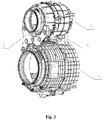
Fig. 3 is a schematic diagram of part of structures of the double-drum washing machine in the present disclosure; -
Fig. 4 is a schematic diagram of breakdown structural of the double-drum washing machine in the present disclosure. - In the drawings: 1, first outer drum; 2, second outer drum; 3, front connecting piece; 4, connecting part; 5, screw.
- It should be noted that these drawings and text descriptions are not intended to limit a conception scope of the present disclosure in any form, but are to describe the concept of the present disclosure to those skilled in the art with reference to specific embodiments.
- In order to make the object, technical solutions and advantages of the embodiments in the present disclosure clearer, a clear and complete description will be given below on technical solutions in the embodiments in combination with accompanying drawings in the embodiments of the present disclosure. The following embodiments are used for describing the present disclosure, rather than for limiting the scope of the present invention.
- In the description of the present disclosure, it should be noted that, the directional or positional relationship indicated by such terms as "upper", "lower", "front", "rear", "left", "right", "vertical", "inner" and "outer" is the directional or positional relationship shown based on the drawings, which is merely for convenient and simplified description of the present disclosure, rather than indicating or implying that the referred device or element must have the specific direction or must be constructed and operated in the specific direction, therefore, it cannot be understood as a limitation to the present disclosure.
- In the description of the present disclosure, it should be noted that, unless otherwise prescribed and defined definitely, the terms "installation", "interconnection" and "connection" should be understood in its broad sense. For example, the "connection" may be a fixed connection, may also be a detachable connection or an integrated connection; and the "connection" may be mechanical connection or electrical connection; and the "interconnection" may be directly interconnection, may also be an indirectly interconnection through an intermediate medium. The specific meaning of the above-mentioned terms in the present disclosure may be understood by those of ordinary skill in the art in light of specific circumstances.
- Refer to
Figs. 1-4 , a double-drum washing machine includes a firstouter drum 1 and a secondouter drum 2 which are respectively provided with a drum inside, wherein the secondouter drum 2 is provided with a connectingpart 4 protruding from a surface of the secondouter drum 2 and integrally molded, the connectingpart 4 extends towards the firstouter drum 1 along a radial direction from the surface of the secondouter drum 2, and an end part of the connectingpart 4 is in detachable connection with the firstouter drum 1. - Preferably, the connecting
part 4 extends towards a mounting clearance between the firstouter drum 1 and the secondouter drum 2 along a radial direction from the surface of the secondouter drum 2. - The connecting
part 4 includes a boss, a bottom part of the boss extends along a circumferential direction of an outer wall of the secondouter drum 2, the end part of the boss is in detachable connection with the firstouter drum 1, and an upper side of the end part is provided with a curved end face, and the curved end face cooperates with an outer wall of the firstouter drum 1. - The curved end face can lift part of a rear part of the first
outer drum 1, thereby plays a certain supporting function. A displacement of the firstouter drum 1 in operation due to vibration is avoided, a burden of connecting components of the first outer drum lis reduced, a service life is prolonged, and a vibration noise is lowered. - A side of the boss is provided with multiple reinforcing ribs extending along an axial direction of the second
outer drum 2 and along a direction vertical to the axial direction. - The reinforcing ribs extending along the axial direction of the second
outer drum 2 have a step-shaped structure, and a height of the step-shaped structure close to the boss is larger than a height of the step-shaped structure far away from the boss. - The above reinforcing rib structure can make a structure of the connecting
part 4 more firm and reliable, thereby the connection of the double drums is ensured to be more stable, and installation is facilitated when the reinforcing rib structure is arranged at one side. - Two ends of the curved end face are not on the same height and are provided with a mounting through hole, the first
outer drum 1 is provided with a bolt column integrally molded corresponding to the mounting through hole, the bolt column is provided with a hollow structure and penetrates through the mounting through hole, and a screw 5 is connected and fixed with the hollow structure via a gasket. - The connecting
part 4 is arranged at an upper side of the secondouter drum 2 and closed to a drum bottom of the secondouter drum 2, and the bolt column is arranged at a lower side of the firstouter drum 1 and closed to a drum bottom of the firstouter drum 1. - The middle portion of the boss is provided with an opening structure suitable for a person to hold by hand. The through structure facilitates mounting and disassembling operations in a process of connecting a first
outer drum 1 and a secondouter drum 2, therefore, time and labor are saved. - The double-drum washing machine includes a front connecting
piece 3 for connecting a front part of the firstouter drum 1 and a front part of the secondouter drum 2. The front connectingpiece 3 includes a U-shape structure on an upper part of the front connectingpiece 3, a left branch end and a right branch end are arranged at the lower part of the U-shape structure. The left branch end and the right branch end are arranged at different heights. Two end parts of the U-shape structure, the left branch end and the right branch end are provided with the mounting through hole. The front part of the firstouter drum 1 and the front part of the secondouter drum 2 are respectively provided with the bolt column which is integrally molded. The bolt column is provided with a hollow structure and penetrates through the mounting through hole, and the screw 5 is connected and fixed with the hollow structure via the gasket. - A circumferential wall of the bolt column is provided with multiple convex ribs which are distributed along an axial direction of the bolt column, and the mounting through hole is a cylindrical hole, as preferably, the mounting through hole is internally provided with a groove corresponding to the convex rib.
- The curbed end face is provided with an elastic buffer layer, and the elastic buffer layer is provided with a surface structure cooperating with an outer wall of the first
outer drum 1. Thereby a noise is further lowered, an impacting effect between the firstouter drum 1 and the boss is reduced, and the structure of the firstouter drum 1 and the structure of the connecting part is protected. - After the above technical solutions are adopted, the present disclosure has the following beneficial effects compared with the prior art:
- 1. A connecting part is molded integrally on an outer drum of the double-drum washing machine, the end part of the connecting part is connected with another outer drum, thereby the double drums are beneficial formed an almost integrated structure, and fewer auxiliary fixed parts are adopted. Looseness of a connecting structure of the double drums during vibration is not easily caused, and the connecting structure is more stable and reliable;
- 2. A structure of the connecting part extends from the surface of a first outer drum to another outer drum, thereby a placement clearance between the first outer drum and the second outer drum is utilized sufficiently with no need of occupying additional space, the structure of the double-drum washing machine is enabled to be more compact, and the vibration noise is lowered;
- 3. As to the double-drum washing machine, no additional counterweights need to be set, the setting of the parts are reduced, therefore, not only the cost is lowered, but also the fewer the parts are, the lower the possibility of fault is, and the stability of the overall structure is beneficial for improving;
- 4. The connecting part or the connecting piece of the double-drum washing machine is provided with a curved surface, etc. cooperating with an edge of the outer drum, and the curved surface can support the outer drum arranged thereon, thereby not only reducing burden of a supporting piece of an outer drum, prolonging service life, but also lowering noise caused by dramatic displacement change of an outer drum in an operating process; and
- 5. The mounting through holes for connecting the outer drums which arranged at an end part of the connecting part are arranged at different heights, after the outer drums are connected, the mounting through holes is beneficial for coordinating displacement change of the double drums during operation, thereby the vibration noise is lowered.
- A double-drum washing machine includes a first
outer drum 1 which provides with a drum inside, and a secondouter drum 2 which provides with a drum inside, and a connecting piece which connects the firstouter drum 1 and the secondouter drum 2 into a whole. At least one end part of the connecting pieces is molded integrally with the firstouter drum 1 or the secondouter drum 2, and the connecting piece is provided with the end part which is in detachable connection with the secondouter drum 2 or the firstouter drum 1. - The connecting piece includes a front connecting
piece 3 for connecting the front parts of the firstouter drum 1 and the secondouter drum 2, and a connectingpart 4 for connecting a rear part of the firstouter drum 1 and a rear part of the secondouter drum 2. - The front connecting
piece 3 is molded integrally at the front part of the firstouter drum 1 or the secondouter drum 2, the end part of the front connectingpiece 3 is in detachable connection with the front part of the secondouter drum 2 or the firstouter drum 1, or/and the connectingpart 4 is molded integrally at the rear part of the firstouter drum 1 or the secondouter drum 2, and the end part of the connectingpart 4 is in detachable connection with the rear part of the secondouter drum 2 or the firstouter drum 1. - Refer to
Figs. 1-4 , in the present embodiment, the connectingpart 4 is molded integrally with the secondouter drum 2, and the connectingpart 4 is provided with an end part which is in detachable connection with the firstouter drum 1. - The end part of the connecting
part 4 is connected with the rear part of the firstouter drum 1 via a bolt. - The end part of the connecting
part 4 is provided with two mounting through holes, the rear part of the firstouter drum 1 is correspondingly provided with two bolt columns. The bolt column is molded integrally with the rear part of the firstouter drum 1. The bolt column is provided with a hollow structure and penetrates through the mounting through hole. The screw 5 is connected with the hollow structure for fixation via a gasket. - The end part of the connecting
part 4 is provided with a curved end face which is coincided to the contact edge at the rear part of the firstouter drum 1. The connectingpart 4 can lift part of the rear part of the firstouter drum 1, thereby plays a certain supporting function. A displacement of the firstouter drum 1 in operation due to vibration is avoided, a burden of connecting components of the first outer drum 1is reduced, a service life is prolonged, and a vibration noise is lowered. - Refer to
Fig. 4 , the connectingpart 4 includes a boss with an upper end face being set to be a curved end face. Two ends of the curved end face are not at the same height and are provided with a mounting through hole. The curved end face cooperates with an edge of a rear part of the firstouter drum 1 or the secondouter drum 2. The rear part of the firstouter drum 1 or the secondouter drum 2 is provided with a bolt column, the bolt column is corresponding to mounting through holes which is at two ends of the curved end face; - A side of the boss is provided with multiple reinforcing ribs, some reinforcing ribs extend along the axial direction of the first
outer drum 1 or the secondouter drum 2, and some reinforcing ribs extend along a direction vertical to the axial direction. The reinforcing ribs extending along an axial direction of the firstouter drum 1 or the secondouter drum 2 have a step-shaped structure. - The boss structure can effectively support the first
outer drum 1, and since it is molded integrally with the secondouter drum 2, the boss structure will not be loosened due to the weight of the firstouter drum 1, thereby the connection between the firstouter drum 1 and the secondouter drum 2 is more stable and reliable. Moreover, the boss structure can play a certain buffer role when the firstouter drum 1 is vibrated, thereby the noise is beneficial for lowered. - The middle portion of the boss is provided with an opening structure. The opening structure can suit for mounting and disassembling operations in a process of connecting the first
outer drum 1 and the secondouter drum 2, therefore, time and labor are saved. - As preferably, the curved end face of the boss is provided with an elastic buffer layer. The elastic buffer layer can further lower noise, and reduce a hit effect between the first
outer drum 1 and the boss, and protect the structure of the firstouter drum 1 and the boss structure. - Refer to
Figs. 1 ,3 and4 , the structure of the front connectingpiece 3 of the present embodiment is specifically as follows: a U-shape structure on an upper part of the front connectingpiece 3, a left branch end arranged at the lower part of the U-shape structure, a right branch end arranged at the lower part of the U-shape structure are included. The left branch end and the right branch end are arranged at different heights. Two end parts of the U-shape structure, the left branch end and the right branch end are provided with the mounting through hole; - The front connecting
piece 3 is configured to connect the front parts of the firstouter drum 1 and the secondouter drum 2. The front part of the firstouter drum 1 is provided with a bolt column which corresponds to the mounting through holes at two end parts of the U-shape structure. An inner concave surface of the U-shape structure cooperates with an outer contour of the firstouter drum 1. The front part of the secondouter drum 2 is provided with bolt columns which correspond to the mounting through holes of the left branch end and the right branch end. - The peripheral wall of the bolt column is provided with multiple convex ribs which are distributed along an axial direction, and the mounting through hole is provided with a groove which corresponds to the convex rib.
- The bolt column is molded integrally with the front parts of the first
outer drum 1 and the secondouter drum 2, and then the overall stability of the connecting structure of the double drums can be improved. - The mounting through hole is arranged at a central position of a thickened circular truncated cone. The structure corresponding to the circular truncated cone of the bolt column is provided with a cylindrical base substrate. In this way, an impact to the connecting piece and the outer drum structure in a vibration process can be buffered, thereby not only the vibration noise is reduced, but also the connecting piece and the outer drum are protected, then the overall stability of the connecting structure of the double drums is improved.
- The present embodiment differs from
embodiment 1 as follows: the connectingpart 4 is molded integrally at the rear part of the firstouter drum 1, and the end part of the connectingpart 4 is connected and fixed with the rear part of the secondouter drum 2 via a bolt. - The end part of the connecting
part 4 is provided with a mounting through hole, the rear part of the secondouter drum 2 is correspondingly provided with a bolt column. The bolt column is molded integrally with the rear part of the secondouter drum 2. The bolt column is provided with a hollow structure and penetrates through the mounting through hole. The screw 5 is connected with the hollow structure for fixation via a gasket. - Other structural characteristics can be set to be identical to or different from
embodiment 1. The setting number of the bolt columns can be changed according to the number of the mounting through holes. - The present embodiment differs from
embodiment 1 as follows: the front connectingpiece 3 is molded integrally at the front part of the secondouter drum 2, and the end part of the front connectingpiece 3 is connected with the front part of the firstouter drum 1 via a bolt. Meanwhile, the connectingpart 4 is molded integrally at the rear part of the secondouter drum 2, and the end part of the connectingpart 4 is connected with the rear part of the firstouter drum 1 via a bolt. - Other structural characteristics can refer to detailed description in
embodiment 1, and other structural characteristics are not limited to the specific structure ofembodiment 1. - For example, the specific structure of the front connecting
piece 3 described inembodiment 1 can be used in the structure setting of the connectingpart 4, similarly, the specific structure of the connectingpart 4 can also be used in the structure setting of the front connectingpiece 3. - The connecting structure of the double drums is more beneficial for setting the first
outer drum 1 and the secondouter drum 2 to be almost integrated, the structure is more compact and stable, the noise is lower, and the installation and detachment are also convenient. - The present embodiment differs from
embodiment 1 as follows: the front connectingpiece 3 is molded integrally at the front part of the firstouter drum 1, and the end part of the front connectingpiece 3 is connected with the front part of the secondouter drum 2 via a bolt, meanwhile, the connectingpart 4 is molded integrally at the rear part of the secondouter drum 2, and the end part of the connectingpart 4 is connected with the rear part of the firstouter drum 1 via a bolt. - Other structural characteristics can refer to detailed description in
embodiment 1, and other structural characteristics are not limited to the specific structure ofembodiment 1. - The connecting structure of the double drums is more beneficial for setting the first
outer drum 1 and the secondouter drum 2 to be almost integrated, the structure is more compact and stable, the noise is lower, and the installation and detachment are also convenient. - What described above are only preferred embodiments of the present disclosure, but are not intended to limiting the scope of the present disclosure in any forms. Although the present disclosure has been disclosed in terms of preferred embodiments, it is not limited thereto. Without departing from the scope of the technical solution of the present disclosure, any persons skilled in the present disclosure can make equivalent embodiments with various alterations and modifications as equivalent variations by utilizing the above-mentioned technical contents. However, without departing from the contents of the technical solution of the present disclosure, any simple changes, equivalent variations and modifications made according to the technical essence of the present disclosure shall all be covered within the scope of the technical solution of the present disclosure.
Claims (10)
- A double-drum washing machine, comprising a first outer drum (1) and a second outer drum (2) which are respectively provided with a drum inside, characterized in that,
the second outer drum (2) is provided with a connecting part (4) protruding from a surface of the second outer drum (2) and integrally molded, the connecting part (4) extends towards the first outer drum (1) along a radial direction from the surface of the second outer drum (2), and an end part of the connecting part (4) is in detachable connection with the first outer drum (1). - The double-drum washing machine according to claim 1, characterized in that the connecting part (4) comprises a boss, a bottom part of the boss extends along a circumferential direction of an outer wall of the second outer drum (2), an end part of the boss is in detachable connection with the first outer drum (1) and an upper side of the end part is provided with a curved end face, and the curved end face cooperates with an outer wall of the first outer drum (1).
- The double-drum washing machine according to claim 2, characterized in that a side of the boss is provided with multiple reinforcing ribs extending along an axial direction of the second outer drum (2) and along a direction vertical to the axial direction.
- The double-drum washing machine according to claim 3, characterized in that the reinforcing ribs extending along the axial direction of the second outer drum (2) have a step-shaped structure, and a height of the step-shaped structure close to the boss is larger than a height of the step-shaped structure far away from the boss.
- The double-drum washing machine according to any of claims 2-4, characterized in that two ends of the curved end face are not on the same height and are provided with a mounting through hole, the first outer drum (1) is provided with a bolt column integrally molded corresponding to the mounting through hole, the bolt column is provided with a hollow structure and penetrates through the mounting through hole, and a screw (5) is connected and fixed with the hollow structure via a gasket.
- The double-drum washing machine according to claim 5, characterized in that the connecting part (4) is arranged at an upper side of the second outer drum (2) and closed to a drum bottom of the second outer drum (2), and the bolt column is arranged at a lower side of the first outer drum (1) and closed to a drum bottom of the first outer drum (1).
- The double-drum washing machine according to any of claims 2-6, characterized in that a middle portion of the boss is provided with an opening structure suitable for a person to hold by hand.
- The double-drum washing machine according to any of claims 1-7, comprising a front connecting piece (3) for connecting a front part of the first outer drum (1) and a front part of the second outer drum (2), characterized in that
the front connecting piece (3) comprises a U-shape structure on an upper part of the front connecting piece (3), a left branch end arranged at a lower part of the U-shape structure and a right branch end arranged at the lower part of the U-shape structure, the left branch end and the right branch end are arranged at different heights, two end parts of the U-shape structure, the left branch end and the right branch end are provided with the mounting through hole, the front part of the first outer drum (1) and the front part of the second outer drum (2) are respectively provided with the bolt column which is integrally molded, the bolt column is provided with a hollow structure and penetrates through the mounting through hole, and the screw (5) is connected and fixed with the hollow structure via the gasket. - The double-drum washing machine according to any of claims 5-8, characterized in that a circumferential wall of the bolt column is provided with multiple convex ribs which are distributed along an axial direction of the bolt column, and the mounting through hole is a cylindrical hole;
preferably, the mounting through hole is internally provided with a groove corresponding to the convex rib. - The double-drum washing machine according to any of claims 5-9, characterized in that the curved end face is provided with an elastic buffer layer, and the elastic buffer layer is provided with a surface structure cooperating with an outer wall of the first outer drum (1).
Applications Claiming Priority (2)
| Application Number | Priority Date | Filing Date | Title |
|---|---|---|---|
| CN201710452878.2A CN109137382B (en) | 2017-06-15 | 2017-06-15 | Double-drum washing machine |
| PCT/CN2018/091310 WO2018228485A1 (en) | 2017-06-15 | 2018-06-14 | Dual-drum washing machine |
Publications (3)
| Publication Number | Publication Date |
|---|---|
| EP3640391A1 true EP3640391A1 (en) | 2020-04-22 |
| EP3640391A4 EP3640391A4 (en) | 2020-04-29 |
| EP3640391B1 EP3640391B1 (en) | 2021-10-20 |
Family
ID=64658940
Family Applications (1)
| Application Number | Title | Priority Date | Filing Date |
|---|---|---|---|
| EP18818358.6A Active EP3640391B1 (en) | 2017-06-15 | 2018-06-14 | Dual-drum washing machine |
Country Status (5)
| Country | Link |
|---|---|
| US (1) | US11236452B2 (en) |
| EP (1) | EP3640391B1 (en) |
| JP (1) | JP7101200B2 (en) |
| CN (1) | CN109137382B (en) |
| WO (1) | WO2018228485A1 (en) |
Cited By (1)
| Publication number | Priority date | Publication date | Assignee | Title |
|---|---|---|---|---|
| WO2022233218A1 (en) * | 2021-05-07 | 2022-11-10 | 青岛海尔滚筒洗衣机有限公司 | Dual-drum washing machine |
Families Citing this family (4)
| Publication number | Priority date | Publication date | Assignee | Title |
|---|---|---|---|---|
| CN111102272B (en) * | 2019-12-27 | 2023-11-24 | 重庆海尔滚筒洗衣机有限公司 | A connecting piece and a double-drum washing machine |
| CN117090006B (en) * | 2023-08-03 | 2025-12-09 | 广州奕至家居科技有限公司 | Clothes treatment equipment and assembling method thereof |
| CN117845543A (en) * | 2023-12-27 | 2024-04-09 | 珠海格力电器股份有限公司 | Outer drum assembly, drum assembly, clothing processing device and control method |
| CN223535450U (en) * | 2024-10-23 | 2025-11-11 | 小米科技(武汉)有限公司 | Clothing processing device |
Family Cites Families (12)
| Publication number | Priority date | Publication date | Assignee | Title |
|---|---|---|---|---|
| KR100331813B1 (en) * | 1999-12-29 | 2002-04-09 | 구자홍 | washing machine having two inner tube and washing method |
| TR200300634T1 (en) * | 2000-08-09 | 2004-02-23 | Ar�El�K Anon�M ��Rket� | Washing machine with multiple drums. |
| CN2441827Y (en) * | 2000-08-31 | 2001-08-08 | 刘易清 | Double drum washing machine with sterilizing function |
| KR100652459B1 (en) * | 2005-11-25 | 2006-12-01 | 엘지전자 주식회사 | Integrated laundry dryer |
| CN103225191A (en) * | 2013-05-13 | 2013-07-31 | 苏州卫生职业技术学院 | Double-drum washing machine capable of simultaneously and separately washing underwear and garments |
| CN104278481B (en) * | 2013-07-09 | 2018-05-01 | 青岛海尔滚筒洗衣机有限公司 | A kind of Double-rotary drum washing machine |
| US10301756B2 (en) | 2013-07-09 | 2019-05-28 | Haier Group Corporation | Dual-drum washing machine |
| KR101555757B1 (en) * | 2013-11-21 | 2015-09-25 | 동부대우전자 주식회사 | Washing machine |
| CN203741590U (en) * | 2014-02-21 | 2014-07-30 | 合肥荣事达三洋电器股份有限公司 | Washing machine |
| CN203741589U (en) * | 2014-02-21 | 2014-07-30 | 合肥荣事达三洋电器股份有限公司 | Double-drum washing machine |
| CN106192290B (en) * | 2014-12-12 | 2020-06-30 | 青岛海尔滚筒洗衣机有限公司 | Drainage-dehydration control method of a multi-drum washing machine |
| CN106544828B (en) * | 2015-09-17 | 2019-08-27 | 青岛海尔滚筒洗衣机有限公司 | Drainage method of a multi-tubular washing machine |
-
2017
- 2017-06-15 CN CN201710452878.2A patent/CN109137382B/en active Active
-
2018
- 2018-06-14 JP JP2019569452A patent/JP7101200B2/en active Active
- 2018-06-14 US US16/620,610 patent/US11236452B2/en active Active
- 2018-06-14 WO PCT/CN2018/091310 patent/WO2018228485A1/en not_active Ceased
- 2018-06-14 EP EP18818358.6A patent/EP3640391B1/en active Active
Cited By (1)
| Publication number | Priority date | Publication date | Assignee | Title |
|---|---|---|---|---|
| WO2022233218A1 (en) * | 2021-05-07 | 2022-11-10 | 青岛海尔滚筒洗衣机有限公司 | Dual-drum washing machine |
Also Published As
| Publication number | Publication date |
|---|---|
| US20200385908A1 (en) | 2020-12-10 |
| US11236452B2 (en) | 2022-02-01 |
| EP3640391B1 (en) | 2021-10-20 |
| EP3640391A4 (en) | 2020-04-29 |
| JP7101200B2 (en) | 2022-07-14 |
| CN109137382A (en) | 2019-01-04 |
| CN109137382B (en) | 2021-12-17 |
| JP2020525078A (en) | 2020-08-27 |
| WO2018228485A1 (en) | 2018-12-20 |
Similar Documents
| Publication | Publication Date | Title |
|---|---|---|
| US11236452B2 (en) | Dual-drum washing machine | |
| US2750239A (en) | Bearing unit for spindles of spinning frames and twisting frames | |
| US3610069A (en) | Molded one-piece balancing ring | |
| CN107055269A (en) | Multifunctional permanent-magnet synchro traction machine | |
| CN112794182A (en) | Hauler encoder mounting structure and hauler | |
| CN208572586U (en) | Display device and shell structure thereof | |
| CN212564094U (en) | Ball bearing seat convenient to dismantle | |
| CN209354875U (en) | A kind of water pump damping base | |
| US6906440B1 (en) | Bracket assembly having a plurality of plates for a dynamoelectric machine | |
| US2916201A (en) | Centrifuge drive spindle arrangement | |
| CN208457526U (en) | A kind of wall type suspension arrangement of display screen casing | |
| CN215137603U (en) | An installation platform suitable for filter barrels | |
| JPH0528917Y2 (en) | ||
| CN207511609U (en) | A kind of novel suspension cable stent | |
| CN210011560U (en) | Upright post rear-mounted double-auxiliary arm structure for tire dismounting machine | |
| CN215870979U (en) | Stable mounting base for elevator motor | |
| CN223087996U (en) | A new spindle transmission mechanism | |
| KR920001612Y1 (en) | Rope Support of Elevator | |
| CN217538288U (en) | Hidden hinge | |
| CN220342363U (en) | Liquid crystal television | |
| JP4737927B2 (en) | Vertical electric pump | |
| CN216824761U (en) | Mahjong tile falling silencing device of mahjong machine | |
| CN219013176U (en) | Cylindrical roller bearing capable of bearing axial load | |
| KR101235743B1 (en) | Motor with compensation for loss-in-weight and drum type washing machine having the same | |
| CN210290511U (en) | Bearing seat with good stability of bonding machine |
Legal Events
| Date | Code | Title | Description |
|---|---|---|---|
| STAA | Information on the status of an ep patent application or granted ep patent |
Free format text: STATUS: THE INTERNATIONAL PUBLICATION HAS BEEN MADE |
|
| PUAI | Public reference made under article 153(3) epc to a published international application that has entered the european phase |
Free format text: ORIGINAL CODE: 0009012 |
|
| STAA | Information on the status of an ep patent application or granted ep patent |
Free format text: STATUS: REQUEST FOR EXAMINATION WAS MADE |
|
| 17P | Request for examination filed |
Effective date: 20200114 |
|
| AK | Designated contracting states |
Kind code of ref document: A1 Designated state(s): AL AT BE BG CH CY CZ DE DK EE ES FI FR GB GR HR HU IE IS IT LI LT LU LV MC MK MT NL NO PL PT RO RS SE SI SK SM TR |
|
| AX | Request for extension of the european patent |
Extension state: BA ME |
|
| A4 | Supplementary search report drawn up and despatched |
Effective date: 20200331 |
|
| RIC1 | Information provided on ipc code assigned before grant |
Ipc: D06F 37/26 20060101ALN20200325BHEP Ipc: D06F 31/00 20060101ALI20200325BHEP Ipc: D06F 37/20 20060101AFI20200325BHEP Ipc: D06F 29/00 20060101ALN20200325BHEP |
|
| DAV | Request for validation of the european patent (deleted) | ||
| DAX | Request for extension of the european patent (deleted) | ||
| RIC1 | Information provided on ipc code assigned before grant |
Ipc: D06F 37/20 20060101AFI20210215BHEP Ipc: D06F 29/00 20060101ALN20210215BHEP Ipc: D06F 31/00 20060101ALI20210215BHEP Ipc: D06F 37/26 20060101ALN20210215BHEP |
|
| RIC1 | Information provided on ipc code assigned before grant |
Ipc: D06F 37/26 20060101ALN20210305BHEP Ipc: D06F 29/00 20060101ALN20210305BHEP Ipc: D06F 31/00 20060101ALI20210305BHEP Ipc: D06F 37/20 20060101AFI20210305BHEP |
|
| RIC1 | Information provided on ipc code assigned before grant |
Ipc: D06F 37/26 20060101ALN20210318BHEP Ipc: D06F 29/00 20060101ALN20210318BHEP Ipc: D06F 31/00 20060101ALI20210318BHEP Ipc: D06F 37/20 20060101AFI20210318BHEP |
|
| RIC1 | Information provided on ipc code assigned before grant |
Ipc: D06F 37/26 20060101ALN20210323BHEP Ipc: D06F 29/00 20060101ALN20210323BHEP Ipc: D06F 31/00 20060101ALI20210323BHEP Ipc: D06F 37/20 20060101AFI20210323BHEP |
|
| GRAP | Despatch of communication of intention to grant a patent |
Free format text: ORIGINAL CODE: EPIDOSNIGR1 |
|
| STAA | Information on the status of an ep patent application or granted ep patent |
Free format text: STATUS: GRANT OF PATENT IS INTENDED |
|
| RIC1 | Information provided on ipc code assigned before grant |
Ipc: D06F 37/26 20060101ALN20210416BHEP Ipc: D06F 29/00 20060101ALN20210416BHEP Ipc: D06F 31/00 20060101ALI20210416BHEP Ipc: D06F 37/20 20060101AFI20210416BHEP |
|
| INTG | Intention to grant announced |
Effective date: 20210506 |
|
| GRAS | Grant fee paid |
Free format text: ORIGINAL CODE: EPIDOSNIGR3 |
|
| GRAA | (expected) grant |
Free format text: ORIGINAL CODE: 0009210 |
|
| STAA | Information on the status of an ep patent application or granted ep patent |
Free format text: STATUS: THE PATENT HAS BEEN GRANTED |
|
| AK | Designated contracting states |
Kind code of ref document: B1 Designated state(s): AL AT BE BG CH CY CZ DE DK EE ES FI FR GB GR HR HU IE IS IT LI LT LU LV MC MK MT NL NO PL PT RO RS SE SI SK SM TR |
|
| REG | Reference to a national code |
Ref country code: GB Ref legal event code: FG4D |
|
| REG | Reference to a national code |
Ref country code: CH Ref legal event code: EP |
|
| REG | Reference to a national code |
Ref country code: IE Ref legal event code: FG4D |
|
| REG | Reference to a national code |
Ref country code: DE Ref legal event code: R096 Ref document number: 602018025454 Country of ref document: DE |
|
| REG | Reference to a national code |
Ref country code: AT Ref legal event code: REF Ref document number: 1440054 Country of ref document: AT Kind code of ref document: T Effective date: 20211115 |
|
| REG | Reference to a national code |
Ref country code: LT Ref legal event code: MG9D |
|
| REG | Reference to a national code |
Ref country code: NL Ref legal event code: MP Effective date: 20211020 |
|
| REG | Reference to a national code |
Ref country code: AT Ref legal event code: MK05 Ref document number: 1440054 Country of ref document: AT Kind code of ref document: T Effective date: 20211020 |
|
| PG25 | Lapsed in a contracting state [announced via postgrant information from national office to epo] |
Ref country code: RS Free format text: LAPSE BECAUSE OF FAILURE TO SUBMIT A TRANSLATION OF THE DESCRIPTION OR TO PAY THE FEE WITHIN THE PRESCRIBED TIME-LIMIT Effective date: 20211020 Ref country code: LT Free format text: LAPSE BECAUSE OF FAILURE TO SUBMIT A TRANSLATION OF THE DESCRIPTION OR TO PAY THE FEE WITHIN THE PRESCRIBED TIME-LIMIT Effective date: 20211020 Ref country code: FI Free format text: LAPSE BECAUSE OF FAILURE TO SUBMIT A TRANSLATION OF THE DESCRIPTION OR TO PAY THE FEE WITHIN THE PRESCRIBED TIME-LIMIT Effective date: 20211020 Ref country code: BG Free format text: LAPSE BECAUSE OF FAILURE TO SUBMIT A TRANSLATION OF THE DESCRIPTION OR TO PAY THE FEE WITHIN THE PRESCRIBED TIME-LIMIT Effective date: 20220120 Ref country code: AT Free format text: LAPSE BECAUSE OF FAILURE TO SUBMIT A TRANSLATION OF THE DESCRIPTION OR TO PAY THE FEE WITHIN THE PRESCRIBED TIME-LIMIT Effective date: 20211020 |
|
| PG25 | Lapsed in a contracting state [announced via postgrant information from national office to epo] |
Ref country code: IS Free format text: LAPSE BECAUSE OF FAILURE TO SUBMIT A TRANSLATION OF THE DESCRIPTION OR TO PAY THE FEE WITHIN THE PRESCRIBED TIME-LIMIT Effective date: 20220220 Ref country code: SE Free format text: LAPSE BECAUSE OF FAILURE TO SUBMIT A TRANSLATION OF THE DESCRIPTION OR TO PAY THE FEE WITHIN THE PRESCRIBED TIME-LIMIT Effective date: 20211020 Ref country code: PT Free format text: LAPSE BECAUSE OF FAILURE TO SUBMIT A TRANSLATION OF THE DESCRIPTION OR TO PAY THE FEE WITHIN THE PRESCRIBED TIME-LIMIT Effective date: 20220221 Ref country code: PL Free format text: LAPSE BECAUSE OF FAILURE TO SUBMIT A TRANSLATION OF THE DESCRIPTION OR TO PAY THE FEE WITHIN THE PRESCRIBED TIME-LIMIT Effective date: 20211020 Ref country code: NO Free format text: LAPSE BECAUSE OF FAILURE TO SUBMIT A TRANSLATION OF THE DESCRIPTION OR TO PAY THE FEE WITHIN THE PRESCRIBED TIME-LIMIT Effective date: 20220120 Ref country code: NL Free format text: LAPSE BECAUSE OF FAILURE TO SUBMIT A TRANSLATION OF THE DESCRIPTION OR TO PAY THE FEE WITHIN THE PRESCRIBED TIME-LIMIT Effective date: 20211020 Ref country code: LV Free format text: LAPSE BECAUSE OF FAILURE TO SUBMIT A TRANSLATION OF THE DESCRIPTION OR TO PAY THE FEE WITHIN THE PRESCRIBED TIME-LIMIT Effective date: 20211020 Ref country code: HR Free format text: LAPSE BECAUSE OF FAILURE TO SUBMIT A TRANSLATION OF THE DESCRIPTION OR TO PAY THE FEE WITHIN THE PRESCRIBED TIME-LIMIT Effective date: 20211020 Ref country code: GR Free format text: LAPSE BECAUSE OF FAILURE TO SUBMIT A TRANSLATION OF THE DESCRIPTION OR TO PAY THE FEE WITHIN THE PRESCRIBED TIME-LIMIT Effective date: 20220121 Ref country code: ES Free format text: LAPSE BECAUSE OF FAILURE TO SUBMIT A TRANSLATION OF THE DESCRIPTION OR TO PAY THE FEE WITHIN THE PRESCRIBED TIME-LIMIT Effective date: 20211020 |
|
| REG | Reference to a national code |
Ref country code: DE Ref legal event code: R097 Ref document number: 602018025454 Country of ref document: DE |
|
| PG25 | Lapsed in a contracting state [announced via postgrant information from national office to epo] |
Ref country code: SM Free format text: LAPSE BECAUSE OF FAILURE TO SUBMIT A TRANSLATION OF THE DESCRIPTION OR TO PAY THE FEE WITHIN THE PRESCRIBED TIME-LIMIT Effective date: 20211020 Ref country code: SK Free format text: LAPSE BECAUSE OF FAILURE TO SUBMIT A TRANSLATION OF THE DESCRIPTION OR TO PAY THE FEE WITHIN THE PRESCRIBED TIME-LIMIT Effective date: 20211020 Ref country code: RO Free format text: LAPSE BECAUSE OF FAILURE TO SUBMIT A TRANSLATION OF THE DESCRIPTION OR TO PAY THE FEE WITHIN THE PRESCRIBED TIME-LIMIT Effective date: 20211020 Ref country code: EE Free format text: LAPSE BECAUSE OF FAILURE TO SUBMIT A TRANSLATION OF THE DESCRIPTION OR TO PAY THE FEE WITHIN THE PRESCRIBED TIME-LIMIT Effective date: 20211020 Ref country code: DK Free format text: LAPSE BECAUSE OF FAILURE TO SUBMIT A TRANSLATION OF THE DESCRIPTION OR TO PAY THE FEE WITHIN THE PRESCRIBED TIME-LIMIT Effective date: 20211020 Ref country code: CZ Free format text: LAPSE BECAUSE OF FAILURE TO SUBMIT A TRANSLATION OF THE DESCRIPTION OR TO PAY THE FEE WITHIN THE PRESCRIBED TIME-LIMIT Effective date: 20211020 |
|
| PLBE | No opposition filed within time limit |
Free format text: ORIGINAL CODE: 0009261 |
|
| STAA | Information on the status of an ep patent application or granted ep patent |
Free format text: STATUS: NO OPPOSITION FILED WITHIN TIME LIMIT |
|
| 26N | No opposition filed |
Effective date: 20220721 |
|
| PG25 | Lapsed in a contracting state [announced via postgrant information from national office to epo] |
Ref country code: AL Free format text: LAPSE BECAUSE OF FAILURE TO SUBMIT A TRANSLATION OF THE DESCRIPTION OR TO PAY THE FEE WITHIN THE PRESCRIBED TIME-LIMIT Effective date: 20211020 |
|
| PG25 | Lapsed in a contracting state [announced via postgrant information from national office to epo] |
Ref country code: SI Free format text: LAPSE BECAUSE OF FAILURE TO SUBMIT A TRANSLATION OF THE DESCRIPTION OR TO PAY THE FEE WITHIN THE PRESCRIBED TIME-LIMIT Effective date: 20211020 |
|
| PG25 | Lapsed in a contracting state [announced via postgrant information from national office to epo] |
Ref country code: MC Free format text: LAPSE BECAUSE OF FAILURE TO SUBMIT A TRANSLATION OF THE DESCRIPTION OR TO PAY THE FEE WITHIN THE PRESCRIBED TIME-LIMIT Effective date: 20211020 |
|
| REG | Reference to a national code |
Ref country code: CH Ref legal event code: PL |
|
| REG | Reference to a national code |
Ref country code: BE Ref legal event code: MM Effective date: 20220630 |
|
| PG25 | Lapsed in a contracting state [announced via postgrant information from national office to epo] |
Ref country code: LU Free format text: LAPSE BECAUSE OF NON-PAYMENT OF DUE FEES Effective date: 20220614 Ref country code: LI Free format text: LAPSE BECAUSE OF NON-PAYMENT OF DUE FEES Effective date: 20220630 Ref country code: IE Free format text: LAPSE BECAUSE OF NON-PAYMENT OF DUE FEES Effective date: 20220614 Ref country code: CH Free format text: LAPSE BECAUSE OF NON-PAYMENT OF DUE FEES Effective date: 20220630 |
|
| PG25 | Lapsed in a contracting state [announced via postgrant information from national office to epo] |
Ref country code: BE Free format text: LAPSE BECAUSE OF NON-PAYMENT OF DUE FEES Effective date: 20220630 |
|
| PG25 | Lapsed in a contracting state [announced via postgrant information from national office to epo] |
Ref country code: MK Free format text: LAPSE BECAUSE OF FAILURE TO SUBMIT A TRANSLATION OF THE DESCRIPTION OR TO PAY THE FEE WITHIN THE PRESCRIBED TIME-LIMIT Effective date: 20211020 Ref country code: CY Free format text: LAPSE BECAUSE OF FAILURE TO SUBMIT A TRANSLATION OF THE DESCRIPTION OR TO PAY THE FEE WITHIN THE PRESCRIBED TIME-LIMIT Effective date: 20211020 |
|
| PG25 | Lapsed in a contracting state [announced via postgrant information from national office to epo] |
Ref country code: HU Free format text: LAPSE BECAUSE OF FAILURE TO SUBMIT A TRANSLATION OF THE DESCRIPTION OR TO PAY THE FEE WITHIN THE PRESCRIBED TIME-LIMIT; INVALID AB INITIO Effective date: 20180614 |
|
| PG25 | Lapsed in a contracting state [announced via postgrant information from national office to epo] |
Ref country code: MT Free format text: LAPSE BECAUSE OF FAILURE TO SUBMIT A TRANSLATION OF THE DESCRIPTION OR TO PAY THE FEE WITHIN THE PRESCRIBED TIME-LIMIT Effective date: 20211020 |
|
| PGFP | Annual fee paid to national office [announced via postgrant information from national office to epo] |
Ref country code: DE Payment date: 20250618 Year of fee payment: 8 |
|
| PGFP | Annual fee paid to national office [announced via postgrant information from national office to epo] |
Ref country code: GB Payment date: 20250625 Year of fee payment: 8 |
|
| PGFP | Annual fee paid to national office [announced via postgrant information from national office to epo] |
Ref country code: FR Payment date: 20250623 Year of fee payment: 8 |
|
| PGFP | Annual fee paid to national office [announced via postgrant information from national office to epo] |
Ref country code: IT Payment date: 20250630 Year of fee payment: 8 |
|
| PG25 | Lapsed in a contracting state [announced via postgrant information from national office to epo] |
Ref country code: TR Free format text: LAPSE BECAUSE OF FAILURE TO SUBMIT A TRANSLATION OF THE DESCRIPTION OR TO PAY THE FEE WITHIN THE PRESCRIBED TIME-LIMIT Effective date: 20211020 |