EP3640361B1 - Method for producing a thermoelectric alloy - Google Patents
Method for producing a thermoelectric alloy Download PDFInfo
- Publication number
- EP3640361B1 EP3640361B1 EP18213379.3A EP18213379A EP3640361B1 EP 3640361 B1 EP3640361 B1 EP 3640361B1 EP 18213379 A EP18213379 A EP 18213379A EP 3640361 B1 EP3640361 B1 EP 3640361B1
- Authority
- EP
- European Patent Office
- Prior art keywords
- thermoelectric
- quartz tube
- thermoelectric alloy
- alloy
- material composition
- Prior art date
- Legal status (The legal status is an assumption and is not a legal conclusion. Google has not performed a legal analysis and makes no representation as to the accuracy of the status listed.)
- Active
Links
Images
Classifications
-
- H—ELECTRICITY
- H10—SEMICONDUCTOR DEVICES; ELECTRIC SOLID-STATE DEVICES NOT OTHERWISE PROVIDED FOR
- H10N—ELECTRIC SOLID-STATE DEVICES NOT OTHERWISE PROVIDED FOR
- H10N10/00—Thermoelectric devices comprising a junction of dissimilar materials, i.e. devices exhibiting Seebeck or Peltier effects
- H10N10/01—Manufacture or treatment
-
- C—CHEMISTRY; METALLURGY
- C22—METALLURGY; FERROUS OR NON-FERROUS ALLOYS; TREATMENT OF ALLOYS OR NON-FERROUS METALS
- C22C—ALLOYS
- C22C28/00—Alloys based on a metal not provided for in groups C22C5/00 - C22C27/00
-
- C—CHEMISTRY; METALLURGY
- C22—METALLURGY; FERROUS OR NON-FERROUS ALLOYS; TREATMENT OF ALLOYS OR NON-FERROUS METALS
- C22C—ALLOYS
- C22C1/00—Making non-ferrous alloys
- C22C1/02—Making non-ferrous alloys by melting
-
- C—CHEMISTRY; METALLURGY
- C22—METALLURGY; FERROUS OR NON-FERROUS ALLOYS; TREATMENT OF ALLOYS OR NON-FERROUS METALS
- C22C—ALLOYS
- C22C12/00—Alloys based on antimony or bismuth
-
- C—CHEMISTRY; METALLURGY
- C23—COATING METALLIC MATERIAL; COATING MATERIAL WITH METALLIC MATERIAL; CHEMICAL SURFACE TREATMENT; DIFFUSION TREATMENT OF METALLIC MATERIAL; COATING BY VACUUM EVAPORATION, BY SPUTTERING, BY ION IMPLANTATION OR BY CHEMICAL VAPOUR DEPOSITION, IN GENERAL; INHIBITING CORROSION OF METALLIC MATERIAL OR INCRUSTATION IN GENERAL
- C23C—COATING METALLIC MATERIAL; COATING MATERIAL WITH METALLIC MATERIAL; SURFACE TREATMENT OF METALLIC MATERIAL BY DIFFUSION INTO THE SURFACE, BY CHEMICAL CONVERSION OR SUBSTITUTION; COATING BY VACUUM EVAPORATION, BY SPUTTERING, BY ION IMPLANTATION OR BY CHEMICAL VAPOUR DEPOSITION, IN GENERAL
- C23C8/00—Solid state diffusion of only non-metal elements into metallic material surfaces; Chemical surface treatment of metallic material by reaction of the surface with a reactive gas, leaving reaction products of surface material in the coating, e.g. conversion coatings, passivation of metals
- C23C8/06—Solid state diffusion of only non-metal elements into metallic material surfaces; Chemical surface treatment of metallic material by reaction of the surface with a reactive gas, leaving reaction products of surface material in the coating, e.g. conversion coatings, passivation of metals using gases
- C23C8/08—Solid state diffusion of only non-metal elements into metallic material surfaces; Chemical surface treatment of metallic material by reaction of the surface with a reactive gas, leaving reaction products of surface material in the coating, e.g. conversion coatings, passivation of metals using gases only one element being applied
- C23C8/20—Carburising
-
- C—CHEMISTRY; METALLURGY
- C23—COATING METALLIC MATERIAL; COATING MATERIAL WITH METALLIC MATERIAL; CHEMICAL SURFACE TREATMENT; DIFFUSION TREATMENT OF METALLIC MATERIAL; COATING BY VACUUM EVAPORATION, BY SPUTTERING, BY ION IMPLANTATION OR BY CHEMICAL VAPOUR DEPOSITION, IN GENERAL; INHIBITING CORROSION OF METALLIC MATERIAL OR INCRUSTATION IN GENERAL
- C23C—COATING METALLIC MATERIAL; COATING MATERIAL WITH METALLIC MATERIAL; SURFACE TREATMENT OF METALLIC MATERIAL BY DIFFUSION INTO THE SURFACE, BY CHEMICAL CONVERSION OR SUBSTITUTION; COATING BY VACUUM EVAPORATION, BY SPUTTERING, BY ION IMPLANTATION OR BY CHEMICAL VAPOUR DEPOSITION, IN GENERAL
- C23C8/00—Solid state diffusion of only non-metal elements into metallic material surfaces; Chemical surface treatment of metallic material by reaction of the surface with a reactive gas, leaving reaction products of surface material in the coating, e.g. conversion coatings, passivation of metals
- C23C8/06—Solid state diffusion of only non-metal elements into metallic material surfaces; Chemical surface treatment of metallic material by reaction of the surface with a reactive gas, leaving reaction products of surface material in the coating, e.g. conversion coatings, passivation of metals using gases
- C23C8/34—Solid state diffusion of only non-metal elements into metallic material surfaces; Chemical surface treatment of metallic material by reaction of the surface with a reactive gas, leaving reaction products of surface material in the coating, e.g. conversion coatings, passivation of metals using gases more than one element being applied in more than one step
-
- C—CHEMISTRY; METALLURGY
- C23—COATING METALLIC MATERIAL; COATING MATERIAL WITH METALLIC MATERIAL; CHEMICAL SURFACE TREATMENT; DIFFUSION TREATMENT OF METALLIC MATERIAL; COATING BY VACUUM EVAPORATION, BY SPUTTERING, BY ION IMPLANTATION OR BY CHEMICAL VAPOUR DEPOSITION, IN GENERAL; INHIBITING CORROSION OF METALLIC MATERIAL OR INCRUSTATION IN GENERAL
- C23C—COATING METALLIC MATERIAL; COATING MATERIAL WITH METALLIC MATERIAL; SURFACE TREATMENT OF METALLIC MATERIAL BY DIFFUSION INTO THE SURFACE, BY CHEMICAL CONVERSION OR SUBSTITUTION; COATING BY VACUUM EVAPORATION, BY SPUTTERING, BY ION IMPLANTATION OR BY CHEMICAL VAPOUR DEPOSITION, IN GENERAL
- C23C8/00—Solid state diffusion of only non-metal elements into metallic material surfaces; Chemical surface treatment of metallic material by reaction of the surface with a reactive gas, leaving reaction products of surface material in the coating, e.g. conversion coatings, passivation of metals
- C23C8/40—Solid state diffusion of only non-metal elements into metallic material surfaces; Chemical surface treatment of metallic material by reaction of the surface with a reactive gas, leaving reaction products of surface material in the coating, e.g. conversion coatings, passivation of metals using liquids, e.g. salt baths, liquid suspensions
- C23C8/42—Solid state diffusion of only non-metal elements into metallic material surfaces; Chemical surface treatment of metallic material by reaction of the surface with a reactive gas, leaving reaction products of surface material in the coating, e.g. conversion coatings, passivation of metals using liquids, e.g. salt baths, liquid suspensions only one element being applied
- C23C8/44—Carburising
-
- C—CHEMISTRY; METALLURGY
- C23—COATING METALLIC MATERIAL; COATING MATERIAL WITH METALLIC MATERIAL; CHEMICAL SURFACE TREATMENT; DIFFUSION TREATMENT OF METALLIC MATERIAL; COATING BY VACUUM EVAPORATION, BY SPUTTERING, BY ION IMPLANTATION OR BY CHEMICAL VAPOUR DEPOSITION, IN GENERAL; INHIBITING CORROSION OF METALLIC MATERIAL OR INCRUSTATION IN GENERAL
- C23C—COATING METALLIC MATERIAL; COATING MATERIAL WITH METALLIC MATERIAL; SURFACE TREATMENT OF METALLIC MATERIAL BY DIFFUSION INTO THE SURFACE, BY CHEMICAL CONVERSION OR SUBSTITUTION; COATING BY VACUUM EVAPORATION, BY SPUTTERING, BY ION IMPLANTATION OR BY CHEMICAL VAPOUR DEPOSITION, IN GENERAL
- C23C8/00—Solid state diffusion of only non-metal elements into metallic material surfaces; Chemical surface treatment of metallic material by reaction of the surface with a reactive gas, leaving reaction products of surface material in the coating, e.g. conversion coatings, passivation of metals
- C23C8/40—Solid state diffusion of only non-metal elements into metallic material surfaces; Chemical surface treatment of metallic material by reaction of the surface with a reactive gas, leaving reaction products of surface material in the coating, e.g. conversion coatings, passivation of metals using liquids, e.g. salt baths, liquid suspensions
- C23C8/58—Solid state diffusion of only non-metal elements into metallic material surfaces; Chemical surface treatment of metallic material by reaction of the surface with a reactive gas, leaving reaction products of surface material in the coating, e.g. conversion coatings, passivation of metals using liquids, e.g. salt baths, liquid suspensions more than one element being applied in more than one step
-
- C—CHEMISTRY; METALLURGY
- C23—COATING METALLIC MATERIAL; COATING MATERIAL WITH METALLIC MATERIAL; CHEMICAL SURFACE TREATMENT; DIFFUSION TREATMENT OF METALLIC MATERIAL; COATING BY VACUUM EVAPORATION, BY SPUTTERING, BY ION IMPLANTATION OR BY CHEMICAL VAPOUR DEPOSITION, IN GENERAL; INHIBITING CORROSION OF METALLIC MATERIAL OR INCRUSTATION IN GENERAL
- C23C—COATING METALLIC MATERIAL; COATING MATERIAL WITH METALLIC MATERIAL; SURFACE TREATMENT OF METALLIC MATERIAL BY DIFFUSION INTO THE SURFACE, BY CHEMICAL CONVERSION OR SUBSTITUTION; COATING BY VACUUM EVAPORATION, BY SPUTTERING, BY ION IMPLANTATION OR BY CHEMICAL VAPOUR DEPOSITION, IN GENERAL
- C23C8/00—Solid state diffusion of only non-metal elements into metallic material surfaces; Chemical surface treatment of metallic material by reaction of the surface with a reactive gas, leaving reaction products of surface material in the coating, e.g. conversion coatings, passivation of metals
- C23C8/60—Solid state diffusion of only non-metal elements into metallic material surfaces; Chemical surface treatment of metallic material by reaction of the surface with a reactive gas, leaving reaction products of surface material in the coating, e.g. conversion coatings, passivation of metals using solids, e.g. powders, pastes
- C23C8/62—Solid state diffusion of only non-metal elements into metallic material surfaces; Chemical surface treatment of metallic material by reaction of the surface with a reactive gas, leaving reaction products of surface material in the coating, e.g. conversion coatings, passivation of metals using solids, e.g. powders, pastes only one element being applied
- C23C8/64—Carburising
-
- C—CHEMISTRY; METALLURGY
- C23—COATING METALLIC MATERIAL; COATING MATERIAL WITH METALLIC MATERIAL; CHEMICAL SURFACE TREATMENT; DIFFUSION TREATMENT OF METALLIC MATERIAL; COATING BY VACUUM EVAPORATION, BY SPUTTERING, BY ION IMPLANTATION OR BY CHEMICAL VAPOUR DEPOSITION, IN GENERAL; INHIBITING CORROSION OF METALLIC MATERIAL OR INCRUSTATION IN GENERAL
- C23C—COATING METALLIC MATERIAL; COATING MATERIAL WITH METALLIC MATERIAL; SURFACE TREATMENT OF METALLIC MATERIAL BY DIFFUSION INTO THE SURFACE, BY CHEMICAL CONVERSION OR SUBSTITUTION; COATING BY VACUUM EVAPORATION, BY SPUTTERING, BY ION IMPLANTATION OR BY CHEMICAL VAPOUR DEPOSITION, IN GENERAL
- C23C8/00—Solid state diffusion of only non-metal elements into metallic material surfaces; Chemical surface treatment of metallic material by reaction of the surface with a reactive gas, leaving reaction products of surface material in the coating, e.g. conversion coatings, passivation of metals
- C23C8/60—Solid state diffusion of only non-metal elements into metallic material surfaces; Chemical surface treatment of metallic material by reaction of the surface with a reactive gas, leaving reaction products of surface material in the coating, e.g. conversion coatings, passivation of metals using solids, e.g. powders, pastes
- C23C8/78—Solid state diffusion of only non-metal elements into metallic material surfaces; Chemical surface treatment of metallic material by reaction of the surface with a reactive gas, leaving reaction products of surface material in the coating, e.g. conversion coatings, passivation of metals using solids, e.g. powders, pastes more than one element being applied in more than one step
-
- H—ELECTRICITY
- H10—SEMICONDUCTOR DEVICES; ELECTRIC SOLID-STATE DEVICES NOT OTHERWISE PROVIDED FOR
- H10N—ELECTRIC SOLID-STATE DEVICES NOT OTHERWISE PROVIDED FOR
- H10N10/00—Thermoelectric devices comprising a junction of dissimilar materials, i.e. devices exhibiting Seebeck or Peltier effects
- H10N10/80—Constructional details
- H10N10/85—Thermoelectric active materials
- H10N10/851—Thermoelectric active materials comprising inorganic compositions
-
- H—ELECTRICITY
- H10—SEMICONDUCTOR DEVICES; ELECTRIC SOLID-STATE DEVICES NOT OTHERWISE PROVIDED FOR
- H10N—ELECTRIC SOLID-STATE DEVICES NOT OTHERWISE PROVIDED FOR
- H10N10/00—Thermoelectric devices comprising a junction of dissimilar materials, i.e. devices exhibiting Seebeck or Peltier effects
- H10N10/80—Constructional details
- H10N10/85—Thermoelectric active materials
- H10N10/851—Thermoelectric active materials comprising inorganic compositions
- H10N10/855—Thermoelectric active materials comprising inorganic compositions comprising compounds containing boron, carbon, oxygen or nitrogen
-
- H—ELECTRICITY
- H10—SEMICONDUCTOR DEVICES; ELECTRIC SOLID-STATE DEVICES NOT OTHERWISE PROVIDED FOR
- H10N—ELECTRIC SOLID-STATE DEVICES NOT OTHERWISE PROVIDED FOR
- H10N10/00—Thermoelectric devices comprising a junction of dissimilar materials, i.e. devices exhibiting Seebeck or Peltier effects
- H10N10/80—Constructional details
- H10N10/85—Thermoelectric active materials
- H10N10/851—Thermoelectric active materials comprising inorganic compositions
- H10N10/8556—Thermoelectric active materials comprising inorganic compositions comprising compounds containing germanium or silicon
-
- C—CHEMISTRY; METALLURGY
- C30—CRYSTAL GROWTH
- C30B—SINGLE-CRYSTAL GROWTH; UNIDIRECTIONAL SOLIDIFICATION OF EUTECTIC MATERIAL OR UNIDIRECTIONAL DEMIXING OF EUTECTOID MATERIAL; REFINING BY ZONE-MELTING OF MATERIAL; PRODUCTION OF A HOMOGENEOUS POLYCRYSTALLINE MATERIAL WITH DEFINED STRUCTURE; SINGLE CRYSTALS OR HOMOGENEOUS POLYCRYSTALLINE MATERIAL WITH DEFINED STRUCTURE; AFTER-TREATMENT OF SINGLE CRYSTALS OR A HOMOGENEOUS POLYCRYSTALLINE MATERIAL WITH DEFINED STRUCTURE; APPARATUS THEREFOR
- C30B29/00—Single crystals or homogeneous polycrystalline material with defined structure characterised by the material or by their shape
- C30B29/10—Inorganic compounds or compositions
- C30B29/52—Alloys
Definitions
- the present invention relates to a method for producing a thermoelectric alloy.
- thermoelectric materials Thermal energy can be efficiently converted into electrical energy by thermoelectric materials.
- Thermoelectric phenomena of the thermoelectric materials can encompass separately conversion mechanisms: Seebeck effect, Peltier effect or Thomson effect. If two sides of a thermoelectric material exist a difference in temperature or voltage, there will be a relative voltage difference between both sides, or one side will be endothermic and the other side will be exotherm ic.
- thermoelectric material can be typically applied in waste heat recovery for electricity production or a thermoelectric cooler.
- thermoelectric efficiency of the thermoelectric material depends on its thermoelectric figure-of-merit, and the thermoelectric figure-of-merit is represented by following formula (I).
- zT S 2 ⁇ T
- thermoelectric figure-of-merit S represents Seebeck coefficient
- ⁇ electrical resistance value
- S 2 / ⁇ power factor of the material
- ⁇ thermal conductivity coefficient
- T Kelvin temperature (K).
- thermoelectric material achieves better thermoelectric conversion efficiency for its higher thermoelectric figure-of-merit.
- the thermoelectric figure-of-merit of commercial thermoelectric materials is about 1.0, and the scope of their applications is restricted since such thermoelectric materials cannot replace compressors (the thermoelectric figure-of-merit is about 3.5) for dissipating heat.
- US 4,061,505 A discloses N-type thermoelectric compositions based on rare-earth metal selected from gadolinium and erbium and chalcogen selected from selenium and tellurium. Choi et al. published thermoelectric properties of n-Type (Pb 1-x Ge x )Te fabricated by hot pressing method ( J.S. Choi et al.
- US 2015/0020862 A1 provides a thermoelectric material containing a matrix and oxide nanoparticles dispersed into the matrix to have improved thermal stability, wherein the oxide nanoparticle forms a coherent interphase interface with the Group 13 element of the chalcogenide-based matrix.
- US 6,043,424 A refers to a thermoelectric alloy essentially consisting of at least one element selected from the group consisting of Bi and Sb and at least one element selected from the group consisting of Te and Se, said alloy being made by a rapid liquid-phase quenching technique achieving about 10 3 to 10 6 degrees K/second.
- JP 2006/222161 A discloses a thermoelectric material, and in particular it discloses a Bi 2 Te 3 -Bi 2 Se 3 composite in a 95:5 ration which includes 0.006wt% carbon.
- thermoelectric alloy and a method for producing the same, so as to improve the disadvantages of the conventional thermoelectric materials.
- thermoelectric alloy according to claim 1.
- a carburizing agent decomposes on heating to generate active carbon atoms during a carburization process, and the active carbon atoms can diffuse into an as-melted thermoelectric alloy material, thereby improving thermoelectric properties of the thermoelectric alloy.
- a starting material is provided and subjected to an oxidation process for producing an oxidized material composition. Based on the oxidized material composition as 100 atom percent (at%), an oxygen content of the oxidized material composition is 0.001 at% to 10 at%.
- the oxidized material composition and a carburizing agent are added into a quartz tube, and the quartz tube is subjected to a sealing process to obtain a sealed quartz tube. Then, a carburization process is performed to the sealed quartz tube, thereby producing the thermoelectric alloy.
- the starting material includes germanium (Ge), tellurium (Te), bismuth (Bi), zinc (Zn), antimony (Sb), selenium (Se), copper (Cu), indium (In), gallium (Ga), silver (Ag), cobalt (Co), iron (Fe) and/or lead (Pb).
- the carburizing agent in a form of a solid, a liquid, a gas and/or a plasma.
- the operation of adding the oxidized material composition and the carburizing agent into the quartz tube comprises performing a carbon coating process by the carburizing agent, so as to form a carbon film on an inner surface of the quartz tube and adding the oxidized material composition into the quartz tube having the carbon film.
- a vacuum degree of the sealed quartz tube is not larger than 0.03 mbar.
- the carburization process includes a heating step, and the heating step is heated from 200°C to a melting point of the starting material.
- a cooling rate of the carburization process is 2°C/hour to 10°C/hour.
- thermoelectric alloy is further subjected to a crystal growth process.
- thermoelectric alloy Based on the thermoelectric alloy as 100 wt%, a carbon content of the thermoelectric alloy is 0.005 wt% to 0.05 wt%.
- the thermoelectric alloy includes P-type thermoelectric alloy and N-type thermoelectric alloy.
- thermoelectric alloy composite Based on an amount of the thermoelectric alloy composite as 100 wt%, an amount of the thermoelectric alloy is at least 10 wt%.
- the carburizing agent is subjected to the carburization process to decompose to generate active carbon atoms, thereby promoting the active carbon atoms to diffuse into the as-melted oxidized material composition, thereby improving thermoelectric properties of the thermoelectric alloy.
- thermoelectric alloy when a content of impurity elements of a thermoelectric alloy is less, an electrical resistance value of the thermoelectric alloy is lower, such that the thermoelectric alloy has higher thermoelectric figure-of-merit and better thermoelectric properties. Therefore, in order to lower the effects of the impurity elements on the thermoelectric properties, starting materials of the thermoelectric alloy all are high purity materials or those subjected to purifying processes for removing the impurity elements therein. For example, as an increasing of an oxygen content of the thermoelectric alloy, the electrical resistance value of the thermoelectric alloy increases, thereby lowering the thermoelectric properties of the thermoelectric alloy. Accordingly, it is strict with purities of the starting materials. Further, it is necessary to stock the starting materials well to prevent the starting materials from being oxidized during storage. However, the thermoelectric figure-of-merit of the thermoelectric alloy does not be outstandingly improved.
- the present invention is firstly subjected the starting materials of the thermoelectric alloy to be oxidized to increase an oxygen content of the starting materials, and then subjecting to a carburization process, thereby increasing a content of carbon diffused in the thermoelectric alloy by reducing the oxidized starting materials, so as to lower thermal conductivity coefficient and increase power factor thereof. Therefore, the thermoelectric properties of the thermoelectric alloy can be efficiently enhanced.
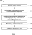
- FIG. 1 is a flow chart showing a method for producing a thermoelectric alloy in accordance with some embodiments of the present invention.
- starting materials are firstly provided, and the starting materials are subjected to an oxidation process, so as to produce an oxidized material composition, shown as operation 110 and operation 120.
- the starting materials Based on chemical compositions of the thermoelectric alloy, the starting materials have corresponding compositions and ratios.
- the starting materials are a mixture.
- the mixture can include metallic materials and/or non-metallic materials.
- the starting material includes germanium (Ge), tellurium (Te), bismuth (Bi), zinc (Zn), antimony (Sb), selenium (Se), copper (Cu), indium (In), gallium (Ga), silver (Ag), cobalt (Co), iron (Fe), lead (Pb).
- purities of each compounds of the starting materials is not lower than 4N for producing the thermoelectric alloy with excellent properties.
- an oxygen content of the oxidized material composition is 0.001 at% to 10 at%.
- the oxygen content of the oxidized material composition preferably can be 1 at% to 6 at%, and more preferably is 2 at% to 5 at%.
- the oxidized material composition and a carburizing agent are added into a quartz tube, and the quartz tube is subjected to a sealing process to form a sealed quartz tube, shown as operation 130.
- the carburizing agent there are no limitations for the carburizing agent, but it is necessary to be as a carbon source during sequential carburization process.
- major compositions of the carburizing agent are carbon atoms, and preferably the carburizing agent does not include other impurity elements, such that the compositions of the thermoelectric alloy can satisfy requirements.
- the carburizing agent can include but be not limited to a solid carbon source, a liquid carbon source, a gaseous carbon source, a plasma carbon source, other suitable carbon sources, or a combination thereof.
- the carburizing agent can include but be not limited to carbon powder, a graphite powder, graphene, diamonds, carbon nanotube, amorphous carbons, fullerenes, other suitable materials, or a combination thereof.
- the carburizing agent and the oxidized material composition can be simultaneously added into the quartz tube.
- the carburizing agent can be formed in or added into the quartz tube before the oxidized material composition is added.
- the quartz tube can firstly be subjected to a carbon coating process to form the carburizing agent on an inner surface of the quartz tube, thereby obtain a quartz tube with a carbon film on the inner surface thereof.
- the oxidized material composition can be added into the quartz tube with the carbon film to be subjected to a sequential sealing process.
- a vacuum degree of the sealed quartz tube is not larger than 0.03 mbar.
- thermoelectric alloy of the present invention After the sealing process is performed, a carburization process is performed to the sealed quartz tube, thereby obtaining the thermoelectric alloy of the present invention, shown as operation 140 and operation 150.
- the carburizing agent (or carbon atoms) in the sealed quartz tube can be reduced to be as the oxidized material composition, and active carbon atoms can diffuse into an as-melted oxidized material composition during the carburization process, thereby enhancing properties of the thermoelectric alloy.
- a carbon content of the thermoelectric alloy can be 0.005 wt% to 0.05 wt%.
- the thermoelectric alloy preferably does not include oxygen atoms. If the thermoelectric alloy includes oxygen atoms, the electrical resistance value of the thermoelectric alloy will be increased so as to decrease the thermoelectric figure-of-merit thereof.
- the carburization process further includes a heating step to promote the carburizing agent to decompose to generate the active carbon atoms and further to subject the active carbon atoms to efficiently be diffused into the thermoelectric alloy.
- the heating step is heated from 200°C to a melting point of the aforementioned starting materials, such that the oxidized material composition is melted and the carbon atoms can diffuse into the oxidized material composition.
- compounds of the oxidized material composition all are melted during the heating step. In other words, when the oxidized material composition is heated to a setting temperature, all compounds of the oxidized material composition are melted.
- the heating step preferably is heated from 200°C to 1100°C, and more preferably is from 200°C to 950°C.
- a furnace is firstly heated from room temperature to 200°C, and then the sealed quartz tube is placed into the furnace (200°C).
- carbon atoms can diffuse into the oxidized material composition to reduce the oxidized material composition.
- the as-reduced oxidized material composition can be melted to form a thermoelectric alloy liquid.
- the oxidized material composition can melted to form an oxidized material composition liquid, the carbon atoms diffuse into the oxidized material composition liquid to reduce the oxidized material composition liquid. And then, the as-reduced oxidized material composition is formed into the thermoelectric alloy.
- the oxidized material composition can firstly be melted and formed into the thermoelectric alloy liquid. Then, the carbon atoms can diffuse into the thermoelectric alloy liquid and reduce oxygen atoms in the thermoelectric alloy liquid.
- the oxygen content of the oxidized material composition is less than 0.001 at%, it will be hard for the thermally decomposed active carbon atoms to diffuse into the thermoelectric alloy because an oxidized degree of the oxidized material composition is too low, thereby decreasing the content of carbon atoms in the thermoelectric alloy and lowering thermoelectric properties of the thermoelectric alloy. If the oxygen content of the oxidized material composition was more than 10 at%, a portion of the oxidized material would not be reduced, such that the thermoelectric material would still include oxygen atoms, thereby enhancing the electrical resistance value of the thermoelectric material and lowering the thermoelectric properties thereof.
- thermoelectric alloy has excellent thermoelectric properties.
- a cooling rate of the carburization process can be 2°C/hour to 10°C/hour.
- the cooling rate falls in the aforementioned range, the as-melted and as-reduced oxidized material composition can be cooled slowly so as to be equipped with more compact structure and better crystal properties, thereby improving properties of the thermoelectric alloy.
- the cooling rate of the carburization process preferably can be 3°C/hour to 8°C/hour, and more preferably is 5°C/hour to 7°C/hour.
- thermoelectric alloy produced by the aforementioned method of the present invention can be selectively subjected to a crystal growth process, thereby improving the crystal properties of the thermoelectric alloy. Therefore, the thermoelectric properties of the bulk thermoelectric alloy produced by the crystal growth process are improved.
- thermoelectric alloy produced by the aforementioned method can be P-type thermoelectric alloy and N-type thermoelectric alloy.
- the thermoelectric alloy has a composition of M1 x1 (B1 y1 C1 z1 ).
- M1 represents a doped metallic element
- M1 can be Li, Na, K, Rb, Cs, Be, Mg, Ca, Sr, Ba, Cu, Ag, Au, Zn, Mn, Fe, Co, Ni, La, Ce, Pr, Nd, Yb, other suitable elements, or a combination thereof.
- B1 can be Al, Ga, In, Sb, Bi, other suitable elements, or a combination thereof.
- C1 can be O, S, Se, Te, F, Cl, Br, I, other suitable elements, or a combination thereof.
- x1 represents a number lager than 0 and smaller than 1.
- y1 represents a number larger than 1.5 and smaller than 2.5.
- z1 represents a number larger than 2.3 and smaller than 3.7.
- the thermoelectric alloy can be Bi 2 Te 3 doped with M1.
- the thermoelectric alloy has a composition of M2 x2 (B2 y2 C2 z2 ).
- M2 represents a doped metallic element, and M2 can be Li, Na, K, Rb, Sr, Mg, Ca, Sr, Ba, Cu, Ag, Au, Zn, Al, Ga, In, As, Sb, Bi, Br, I, other suitable elements, or a combination thereof.
- B2 can be Si, Ge, Sn, Pb, other suitable elements, or a combination thereof.
- C2 can be N, P, As, Sb, Bi, Te, other suitable elements, or a combination thereof.
- x2 represent a number lager than 0.02 and smaller then 0.2.
- y2 represents a number larger than 0.7 and smaller than 1.3.
- z2 represent a number larger than 0.7 and smaller than 1.3.
- the thermoelectric alloy can be PbTe or GeTe doped with M2.
- the thermoelectric alloy has a composition of M3 x3 (B3 y3 C3 z3 ).
- M3 represents a doped metallic element, and M3 can be Li, Na, K, Cs, Mg, Ca, Sr, Ba, Cu, Ag, Au, Zn, La, Ce, Mn, Fe, Co, Ni, other suitable elements, or a combination thereof.
- B3 can be Al, Ga, In, Zn, Cd, other suitable elements, or a combination thereof.
- C3 can be N, P, As, Sb, Bi, Se, other suitable elements, or a combination thereof.
- x3 represents a number larger than 0 and smaller than 0.5.
- y3 represents a number larger than 2.7 and smaller than 4.4.
- z3 represents a number larger than 2.5 and smaller than 3.5.
- the thermoelectric alloy can be ZnSb, Zn 4 Sb 3 , In 4 Se 3 or InSb doped with M3.
- the thermoelectric alloy has a composition of M4 x4 (B4 y4 C4 z4 ).
- M4 represents a doped metallic element, and M4 can be Li, Cs, Rb, Ba, Ga, In, Tl, La, Ce, Pr, Nd, Yb, other suitable elements, or a combination thereof.
- B4 can be Fe, Co, Ni, Ru, Rh, Pd, other suitable elements, or a combination thereof.
- C4 can be As, Sb, other suitable elements, or a combination thereof.
- x4 represents a number larger than 0 and smaller than 0.4.
- y4 represents a number larger than 0.7 and smaller than 1.3.
- z4 represents a number larger than 2.5 and smaller than 3.5.
- the thermoelectric alloy can be FeCoSb 3 doped with M4.
- the thermoelectric alloy has a composition of M5 x5 (A5 p5 B5 y5 C5 z5 ).
- M5 represents a doped metallic element, and M5 can be Li, Na, K, Cs, Cl, Br, I, other suitable elements, or a combination thereof.
- A5 can be Cu, Ag, Au, other suitable elements, or a combination thereof.
- B5 can be Ga, In, Ge, Sn, As, Sb, Bi, other suitable elements, or a combination thereof.
- C5 can be S, Se, Te, other suitable elements, or a combination thereof.
- x5 represents a number larger than 0 and smaller than 0.2.
- p5 represents a number larger than 0.7 and smaller than 1.3.
- y5 represents a number larger than 0.7 and smaller than 1.3.
- z5 represents a number larger than 1.7 and smaller than 2.3.
- the thermoelectric alloy can be AgSbTe 2 or CuInSe 2 doped with M5.
- thermoelectric alloy can be mixed with other conventional thermoelectric alloys to form a thermoelectric alloy composite, such that the thermoelectric alloy composite has excellent thermoelectric figure-of-merit.
- a content of the thermoelectric alloy of the present invention is at least 10 wt%, preferably is 10 wt% to 80 wt%, and more preferably is 50 wt% to 60 wt%.
- thermoelectric alloy Because the thermally decomposed active carbon atoms can diffuse into the as-melted oxidized material composition during the aforementioned carburization process, the thermal conductivity coefficient of the thermoelectric alloy can be decreased or the power factor thereof can be enhanced. Therefore, the thermoelectric alloy has better thermoelectric properties.
- Copper metals (Cu), bismuth metals (Bi) and tellurium metals (Te) with purity equal to or higher than 4N were firstly provided, and those metals were subjected to an oxidation process to obtain an oxidized material composition including copper oxide, bismuth oxide and tellurium dioxide.
- An oxygen content of the oxidized material composition was 4 at%.
- a carbon coating process was performed to form a carbon film on an inner surface of a quartz tube.
- the aforementioned oxidized material composition was added into the quartz tube with the carbon film on the inner surface, and air in the quartz tube was discharged by vacuum pump to decrease a vacuum degree of the quartz tube.
- thermoelectric alloy was evaluated according to the following evaluation method of thermoelectric figure-of-merit, and the result thereof was described as follows.
- Stibium metals (Sb), germanium metals (Ge) and tellurium metals (Te) with purity equal to or higher than 4N were firstly provided, and those metals were subjected to an oxidation process to obtain an oxidized material composition including stibium oxide, germanium oxide and tellurium dioxide.
- An oxygen content of the oxidized material composition was 10 at%.
- a carbon coating process was performed to form a carbon film on an inner surface of a quartz tube.
- the aforementioned oxidized material composition was added into the quartz tube with the carbon film on the inner surface, and air in the quartz tube was discharged by vacuum pump to decrease a vacuum degree of the quartz tube.
- thermoelectric alloy was evaluated according to the following evaluation method of thermoelectric figure-of-merit, and the result thereof was described as follows.
- Comparative Embodiment 1 was practiced with the same compositions and amounts of the starting materials as in Embodiment 1, but the difference therebetween resides in that the starting materials of Comparative Embodiment 1 were placed into a quartz tube and subjected to the sealing process rather than being subjected to the oxidation process of Embodiment 1.
- thermoelectric alloy was evaluated according to the following evaluation method of thermoelectric figure-of-merit, and the result thereof was described as follows.
- Comparative Embodiment 2 was practiced with the same compositions and amounts of the starting materials as in Embodiment 2, but the difference therebetween resides in that the starting materials of Comparative Embodiment 2 were placed into a quartz tube and subjected to the sealing process rather than being subjected to the oxidation process of Embodiment 2.
- thermoelectric alloy was evaluated according to the following evaluation method of thermoelectric figure-of-merit, and the result thereof was described as follows.
- thermoelectric alloy produced by Embodiments 1 to 2 and Comparative Embodiments 1 to 2 were respectively measured by a temperature-dependent measurement system (manufactured by ULVAC-RIKO, and the model is ZEM-3).
- a temperature-dependent measurement system manufactured by ULVAC-RIKO, and the model is ZEM-3.
- a testing sample of the thermoelectric alloy was fixed by two nickel electrodes, and two thermal couples were disposed to measure temperature difference of the testing sample. The temperature difference was 7K, 10K, 13K or 16K. Then, a pressure of a measurement chamber was lowered to 10 -2 torr, and an inert gas with a purity of 6N was introduced.
- a mirror amount of a high purity helium gas was introduced to prevent the testing sample from oxidation reaction at high temperature.
- a testing voltage was a fixed value, and an electrical current (a maximum value of the current was 130 mA) was adjusted by an electrical resistance value of the testing sample, thereby calculating the electrical resistance value ( ⁇ ) and Seebeck coefficient (S) by computer software.
- thermoelectric alloy a thermal diffusivity and conductivity laser flash apparatus (LFA, manufactured by Netzsch, and the model is LFA 457).
- LFA thermal diffusivity and conductivity laser flash apparatus
- a side of the testing sample of the thermoelectric alloy was heated by laser light, and a temperature of an opposite side of the testing sample was measured by an infrared sensor (or a thermal couple), such that a temperature variation of the testing sample in a period of time can be detected.
- the testing sample of the thermoelectric alloy is a round sample with a diameter of 7 mm and a thickness of 1.5 mm to 2 mm.
- the thermal conductivity coefficient ( ⁇ ) of the thermoelectric alloy of Embodiments 1 to 2 and Comparative Embodiments 1 to 2 was calculated according to the following formula (II).
- ⁇ DC p d
- D represents the temperature variation
- d represents a density of the testing sample.
- thermoelectric figure-of-merit of the thermoelectric alloy of Embodiments 1 to 2 and Comparative Embodiments 1 to 2 at different temperature was calculated according to the aforementioned formula (I).
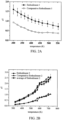
- FIG. 2A is a broken line graph of the thermoelectric figure-of-merit ( zT ) of the thermoelectric alloy at different temperatures in accordance with Embodiment 1 and Comparative Embodiment 1 of the present invention
- FIG. 2B is a broken line graph of the thermoelectric figure-of-merit ( zT ) of the thermoelectric alloy at different temperatures in accordance with Embodiment 2 and Comparative Embodiment 2 of the present invention.
- thermoelectric figure-of-merit (zT) of the thermoelectric alloy of Embodiment 1 at 300K (26.85°C) is 1.7
- thermoelectric figure-of-merit of the thermoelectric alloy of Comparative Embodiment 1 at 300K (26.85°C) is 1.2
- thermoelectric alloy of Embodiment 1 has higher thermoelectric figure-of-merit.
- thermoelectric figure-of-merit of the thermoelectric alloy of Embodiment 1 at 300K is twice as high as that of a commercial thermoelectric alloy (N-type TeSe doped with Bi, and the thermoelectric figure-of-merit thereof is 0.85 to 1.04).
- thermoelectric figure-of-merit of the thermoelectric alloy of Embodiment 2 at 723K (449.85°C) is 2.5
- thermoelectric figure-of-merit of the thermoelectric alloy of Comparative Embodiment 2 at 300K (449.85°C) is 1.0
- thermoelectric alloy of Comparative Embodiment 2 at 300K 449.85°C
- the method of the present invention subjects the starting materials to be oxidized by the oxidation process.
- the oxidized starting materials can be reduced by the active carbon atoms produced by the sequential carburization process, and the active carbon atoms diffuse into the as-melted oxidized material composition, such that the thermal conductivity coefficient of the thermoelectric alloy is decreased and the power factor thereof is increased.
- the thermoelectric properties of the thermoelectric alloy are improved.
Landscapes
- Chemical & Material Sciences (AREA)
- Engineering & Computer Science (AREA)
- Materials Engineering (AREA)
- Mechanical Engineering (AREA)
- Metallurgy (AREA)
- Organic Chemistry (AREA)
- Chemical Kinetics & Catalysis (AREA)
- Inorganic Chemistry (AREA)
- Manufacturing & Machinery (AREA)
- Powder Metallurgy (AREA)
- Manufacture Of Metal Powder And Suspensions Thereof (AREA)
Description
- The present invention relates to a method for producing a thermoelectric alloy.
- Thermal energy can be efficiently converted into electrical energy by thermoelectric materials. Thermoelectric phenomena of the thermoelectric materials can encompass separately conversion mechanisms: Seebeck effect, Peltier effect or Thomson effect. If two sides of a thermoelectric material exist a difference in temperature or voltage, there will be a relative voltage difference between both sides, or one side will be endothermic and the other side will be exotherm ic.
- Accordingly, based on the aforementioned thermoelectric phenomena, the thermoelectric material can be typically applied in waste heat recovery for electricity production or a thermoelectric cooler.
- Furthermore, thermoelectric efficiency of the thermoelectric material depends on its thermoelectric figure-of-merit, and the thermoelectric figure-of-merit is represented by following formula (I).

- In the formula (I), zT represents thermoelectric figure-of-merit, S represents Seebeck coefficient, ρ represents electrical resistance value, S2 /ρ represents power factor of the material, κ represents thermal conductivity coefficient, and T is Kelvin temperature (K).
- A thermoelectric material achieves better thermoelectric conversion efficiency for its higher thermoelectric figure-of-merit. However, the thermoelectric figure-of-merit of commercial thermoelectric materials is about 1.0, and the scope of their applications is restricted since such thermoelectric materials cannot replace compressors (the thermoelectric figure-of-merit is about 3.5) for dissipating heat.
US 4,061,505 A discloses N-type thermoelectric compositions based on rare-earth metal selected from gadolinium and erbium and chalcogen selected from selenium and tellurium. Choi et al. published thermoelectric properties of n-Type (Pb1-xGex)Te fabricated by hot pressing method (J.S. Choi et al. 16th International Conference on Thermoelectrics (1997) DOI 10.1109/ICT.1997.667089, ISBN; 978-0-7803-4057-2).
US 2015/0020862 A1 provides a thermoelectric material containing a matrix and oxide nanoparticles dispersed into the matrix to have improved thermal stability, wherein the oxide nanoparticle forms a coherent interphase interface with the Group 13 element of the chalcogenide-based matrix.US 6,043,424 A refers to a thermoelectric alloy essentially consisting of at least one element selected from the group consisting of Bi and Sb and at least one element selected from the group consisting of Te and Se, said alloy being made by a rapid liquid-phase quenching technique achieving about 103 to 106 degrees K/second.
JP 2006/222161 A - In view of the above, there is a need to provide a thermoelectric alloy and a method for producing the same, so as to improve the disadvantages of the conventional thermoelectric materials.
- Therefore, the present invention provides a method for producing a thermoelectric alloy according to
claim 1. A carburizing agent decomposes on heating to generate active carbon atoms during a carburization process, and the active carbon atoms can diffuse into an as-melted thermoelectric alloy material, thereby improving thermoelectric properties of the thermoelectric alloy. - A starting material is provided and subjected to an oxidation process for producing an oxidized material composition. Based on the oxidized material composition as 100 atom percent (at%), an oxygen content of the oxidized material composition is 0.001 at% to 10 at%. Next, the oxidized material composition and a carburizing agent are added into a quartz tube, and the quartz tube is subjected to a sealing process to obtain a sealed quartz tube. Then, a carburization process is performed to the sealed quartz tube, thereby producing the thermoelectric alloy.
- According to the present invention, the starting material includes germanium (Ge), tellurium (Te), bismuth (Bi), zinc (Zn), antimony (Sb), selenium (Se), copper (Cu), indium (In), gallium (Ga), silver (Ag), cobalt (Co), iron (Fe) and/or lead (Pb).
- According to another embodiment of the present invention, the carburizing agent in a form of a solid, a liquid, a gas and/or a plasma.
- According to yet another embodiment of the present invention, the operation of adding the oxidized material composition and the carburizing agent into the quartz tube comprises performing a carbon coating process by the carburizing agent, so as to form a carbon film on an inner surface of the quartz tube and adding the oxidized material composition into the quartz tube having the carbon film.
- According to the present invention, a vacuum degree of the sealed quartz tube is not larger than 0.03 mbar.
- The carburization process includes a heating step, and the heating step is heated from 200°C to a melting point of the starting material.
- According to yet another embodiment of the present invention, a cooling rate of the carburization process is 2°C/hour to 10°C/hour.
- According to yet another embodiment of the present invention, after the carburization process is performed, the thermoelectric alloy is further subjected to a crystal growth process.
- According to the aforementioned aspect, a thermoelectric alloy is disclosed. Based on the thermoelectric alloy as 100 wt%, a carbon content of the thermoelectric alloy is 0.005 wt% to 0.05 wt%.
- According to one embodiment of the present disclosure, the thermoelectric alloy includes P-type thermoelectric alloy and N-type thermoelectric alloy.
- According to the aforementioned aspect, a thermoelectric alloy composite is disclosed. Based on an amount of the thermoelectric alloy composite as 100 wt%, an amount of the thermoelectric alloy is at least 10 wt%.
- In the method of the present invention, the carburizing agent is subjected to the carburization process to decompose to generate active carbon atoms, thereby promoting the active carbon atoms to diffuse into the as-melted oxidized material composition, thereby improving thermoelectric properties of the thermoelectric alloy.
- The invention can be more fully understood by reading the following detailed description with reference made to the accompanying drawings as follows:
-
FIG. 1 is a flow chart showing a method for producing a thermoelectric alloy in accordance with some embodiments of the present invention. -
FIG. 2A is a broken line graph of the thermoelectric figure-of-merit (zT) of the thermoelectric alloy at different temperatures in accordance withEmbodiment 1 andComparative Embodiment 1 of the present invention. -
FIG. 2B is a broken line graph of the thermoelectric figure-of-merit (zT) of the thermoelectric alloy at different temperatures in accordance withEmbodiment 2 andComparative Embodiment 2 of the present invention. - In the following description, several specific details are presented to provide a thorough understanding of the device structures according to embodiments of the present invention. One skilled in the relevant art will recognize, however, that the embodiments of the present invention provide many applicable inventive concepts which can be practiced in various specific contents. The specific embodiments discussed hereinafter are used for explaining but not limiting the scope of the present invention, which is defined in the appended claims.
- Generally, when a content of impurity elements of a thermoelectric alloy is less, an electrical resistance value of the thermoelectric alloy is lower, such that the thermoelectric alloy has higher thermoelectric figure-of-merit and better thermoelectric properties. Therefore, in order to lower the effects of the impurity elements on the thermoelectric properties, starting materials of the thermoelectric alloy all are high purity materials or those subjected to purifying processes for removing the impurity elements therein. For example, as an increasing of an oxygen content of the thermoelectric alloy, the electrical resistance value of the thermoelectric alloy increases, thereby lowering the thermoelectric properties of the thermoelectric alloy. Accordingly, it is strict with purities of the starting materials. Further, it is necessary to stock the starting materials well to prevent the starting materials from being oxidized during storage. However, the thermoelectric figure-of-merit of the thermoelectric alloy does not be outstandingly improved.
- Accordingly, the present invention is firstly subjected the starting materials of the thermoelectric alloy to be oxidized to increase an oxygen content of the starting materials, and then subjecting to a carburization process, thereby increasing a content of carbon diffused in the thermoelectric alloy by reducing the oxidized starting materials, so as to lower thermal conductivity coefficient and increase power factor thereof. Therefore, the thermoelectric properties of the thermoelectric alloy can be efficiently enhanced.
- Referring to
FIG. 1. FIG. 1 is a flow chart showing a method for producing a thermoelectric alloy in accordance with some embodiments of the present invention. In themethod 100, starting materials are firstly provided, and the starting materials are subjected to an oxidation process, so as to produce an oxidized material composition, shown asoperation 110 andoperation 120. Based on chemical compositions of the thermoelectric alloy, the starting materials have corresponding compositions and ratios. In some embodiments, the starting materials are a mixture. In those embodiments, the mixture can include metallic materials and/or non-metallic materials. In the invention, the starting material includes germanium (Ge), tellurium (Te), bismuth (Bi), zinc (Zn), antimony (Sb), selenium (Se), copper (Cu), indium (In), gallium (Ga), silver (Ag), cobalt (Co), iron (Fe), lead (Pb). According to the invention, purities of each compounds of the starting materials is not lower than 4N for producing the thermoelectric alloy with excellent properties. - Based on the oxidized material composition produced by
operation 120 as 100 atom percent (at%), an oxygen content of the oxidized material composition is 0.001 at% to 10 at%. In some embodiments, the oxygen content of the oxidized material composition preferably can be 1 at% to 6 at%, and more preferably is 2 at% to 5 at%. - Then, the oxidized material composition and a carburizing agent are added into a quartz tube, and the quartz tube is subjected to a sealing process to form a sealed quartz tube, shown as
operation 130. In some embodiments, there are no limitations for the carburizing agent, but it is necessary to be as a carbon source during sequential carburization process. In some embodiments, major compositions of the carburizing agent are carbon atoms, and preferably the carburizing agent does not include other impurity elements, such that the compositions of the thermoelectric alloy can satisfy requirements. In some embodiments, the carburizing agent can include but be not limited to a solid carbon source, a liquid carbon source, a gaseous carbon source, a plasma carbon source, other suitable carbon sources, or a combination thereof. For example, the carburizing agent can include but be not limited to carbon powder, a graphite powder, graphene, diamonds, carbon nanotube, amorphous carbons, fullerenes, other suitable materials, or a combination thereof. - In some embodiments, the carburizing agent and the oxidized material composition can be simultaneously added into the quartz tube. In other embodiments, the carburizing agent can be formed in or added into the quartz tube before the oxidized material composition is added. For example, the quartz tube can firstly be subjected to a carbon coating process to form the carburizing agent on an inner surface of the quartz tube, thereby obtain a quartz tube with a carbon film on the inner surface thereof. Then, the oxidized material composition can be added into the quartz tube with the carbon film to be subjected to a sequential sealing process.
- When the sealing process is performed, air in the quartz tube is discharged by vacuum pump, and a tube orifice of the quartz tube is sealed by an oxy-gas burning torch to seal the quartz tube. A vacuum degree of the sealed quartz tube is not larger than 0.03 mbar.
- After the sealing process is performed, a carburization process is performed to the sealed quartz tube, thereby obtaining the thermoelectric alloy of the present invention, shown as
operation 140 andoperation 150. When the carburization process is performed, the carburizing agent (or carbon atoms) in the sealed quartz tube can be reduced to be as the oxidized material composition, and active carbon atoms can diffuse into an as-melted oxidized material composition during the carburization process, thereby enhancing properties of the thermoelectric alloy. In some embodiments, based on the thermoelectric alloy as 100 wt%, a carbon content of the thermoelectric alloy can be 0.005 wt% to 0.05 wt%. In some embodiments, the thermoelectric alloy preferably does not include oxygen atoms. If the thermoelectric alloy includes oxygen atoms, the electrical resistance value of the thermoelectric alloy will be increased so as to decrease the thermoelectric figure-of-merit thereof. - The carburization process further includes a heating step to promote the carburizing agent to decompose to generate the active carbon atoms and further to subject the active carbon atoms to efficiently be diffused into the thermoelectric alloy. The heating step is heated from 200°C to a melting point of the aforementioned starting materials, such that the oxidized material composition is melted and the carbon atoms can diffuse into the oxidized material composition. Preferably, compounds of the oxidized material composition all are melted during the heating step. In other words, when the oxidized material composition is heated to a setting temperature, all compounds of the oxidized material composition are melted. In some embodiments, the heating step preferably is heated from 200°C to 1100°C, and more preferably is from 200°C to 950°C. In some embodiments, when the carburization process is performed, a furnace is firstly heated from room temperature to 200°C, and then the sealed quartz tube is placed into the furnace (200°C). In some embodiments, during a heating stage of the carburization process, carbon atoms can diffuse into the oxidized material composition to reduce the oxidized material composition. Next, the as-reduced oxidized material composition can be melted to form a thermoelectric alloy liquid. In some embodiments, during the heating stage of the carburization process, the oxidized material composition can melted to form an oxidized material composition liquid, the carbon atoms diffuse into the oxidized material composition liquid to reduce the oxidized material composition liquid. And then, the as-reduced oxidized material composition is formed into the thermoelectric alloy. In some embodiments, during the heating stage of the carburization process, the oxidized material composition can firstly be melted and formed into the thermoelectric alloy liquid. Then, the carbon atoms can diffuse into the thermoelectric alloy liquid and reduce oxygen atoms in the thermoelectric alloy liquid.
- In the carburization process, if the oxygen content of the oxidized material composition is less than 0.001 at%, it will be hard for the thermally decomposed active carbon atoms to diffuse into the thermoelectric alloy because an oxidized degree of the oxidized material composition is too low, thereby decreasing the content of carbon atoms in the thermoelectric alloy and lowering thermoelectric properties of the thermoelectric alloy. If the oxygen content of the oxidized material composition was more than 10 at%, a portion of the oxidized material would not be reduced, such that the thermoelectric material would still include oxygen atoms, thereby enhancing the electrical resistance value of the thermoelectric material and lowering the thermoelectric properties thereof.
- Besides, in the carburization process, when a vacuum degree of the sealed quartz tube is not larger than 0.03 mbar, an interior of the sealed quartz tube is an anoxic environment. Thus, the oxidized material composition can be more efficiently reduced by the active carbon atoms produced by the carburization process, and the active carbon atoms can efficiently diffuse into the as-melted oxidized material composition without being affected by oxygen atoms in the environment, thereby decreasing a thermal conductivity coefficient and increasing power factor of the thermoelectric alloy. Therefore, the thermoelectric alloy has excellent thermoelectric properties.
- After the high temperature carburization process is performed, a cooling rate of the carburization process can be 2°C/hour to 10°C/hour. When the cooling rate falls in the aforementioned range, the as-melted and as-reduced oxidized material composition can be cooled slowly so as to be equipped with more compact structure and better crystal properties, thereby improving properties of the thermoelectric alloy. In some embodiments, the cooling rate of the carburization process preferably can be 3°C/hour to 8°C/hour, and more preferably is 5°C/hour to 7°C/hour.
- After the aforementioned carburization process is performed, the thermoelectric alloy produced by the aforementioned method of the present invention can be selectively subjected to a crystal growth process, thereby improving the crystal properties of the thermoelectric alloy. Therefore, the thermoelectric properties of the bulk thermoelectric alloy produced by the crystal growth process are improved.
- In on example, based on amounts and compositions of the starting materials, the thermoelectric alloy produced by the aforementioned method can be P-type thermoelectric alloy and N-type thermoelectric alloy.
- In some examples, the thermoelectric alloy has a composition of M1x1(B1y1C1z1). M1 represents a doped metallic element, and M1 can be Li, Na, K, Rb, Cs, Be, Mg, Ca, Sr, Ba, Cu, Ag, Au, Zn, Mn, Fe, Co, Ni, La, Ce, Pr, Nd, Yb, other suitable elements, or a combination thereof. B1 can be Al, Ga, In, Sb, Bi, other suitable elements, or a combination thereof. C1 can be O, S, Se, Te, F, Cl, Br, I, other suitable elements, or a combination thereof. x1 represents a number lager than 0 and smaller than 1. y1 represents a number larger than 1.5 and smaller than 2.5. z1 represents a number larger than 2.3 and smaller than 3.7. For example, the thermoelectric alloy can be Bi2Te3 doped with M1.
- In some examples, the thermoelectric alloy has a composition of M2x2(B2y2C2z2). M2 represents a doped metallic element, and M2 can be Li, Na, K, Rb, Sr, Mg, Ca, Sr, Ba, Cu, Ag, Au, Zn, Al, Ga, In, As, Sb, Bi, Br, I, other suitable elements, or a combination thereof. B2 can be Si, Ge, Sn, Pb, other suitable elements, or a combination thereof. C2 can be N, P, As, Sb, Bi, Te, other suitable elements, or a combination thereof. x2 represent a number lager than 0.02 and smaller then 0.2. y2 represents a number larger than 0.7 and smaller than 1.3. z2 represent a number larger than 0.7 and smaller than 1.3. For example, the thermoelectric alloy can be PbTe or GeTe doped with M2.
- In some examples, the thermoelectric alloy has a composition of M3x3(B3y3C3z3). M3 represents a doped metallic element, and M3 can be Li, Na, K, Cs, Mg, Ca, Sr, Ba, Cu, Ag, Au, Zn, La, Ce, Mn, Fe, Co, Ni, other suitable elements, or a combination thereof. B3 can be Al, Ga, In, Zn, Cd, other suitable elements, or a combination thereof. C3 can be N, P, As, Sb, Bi, Se, other suitable elements, or a combination thereof. x3 represents a number larger than 0 and smaller than 0.5. y3 represents a number larger than 2.7 and smaller than 4.4. z3 represents a number larger than 2.5 and smaller than 3.5. For example, the thermoelectric alloy can be ZnSb, Zn4Sb3, In4Se3 or InSb doped with M3.
- In some examples, the thermoelectric alloy has a composition of M4x4(B4y4C4z4). M4 represents a doped metallic element, and M4 can be Li, Cs, Rb, Ba, Ga, In, Tl, La, Ce, Pr, Nd, Yb, other suitable elements, or a combination thereof. B4 can be Fe, Co, Ni, Ru, Rh, Pd, other suitable elements, or a combination thereof. C4 can be As, Sb, other suitable elements, or a combination thereof. x4 represents a number larger than 0 and smaller than 0.4. y4 represents a number larger than 0.7 and smaller than 1.3. z4 represents a number larger than 2.5 and smaller than 3.5. For example, the thermoelectric alloy can be FeCoSb3 doped with M4.
- In some examples, the thermoelectric alloy has a composition of M5x5(A5p5B5y5C5z5). M5 represents a doped metallic element, and M5 can be Li, Na, K, Cs, Cl, Br, I, other suitable elements, or a combination thereof. A5 can be Cu, Ag, Au, other suitable elements, or a combination thereof. B5 can be Ga, In, Ge, Sn, As, Sb, Bi, other suitable elements, or a combination thereof. C5 can be S, Se, Te, other suitable elements, or a combination thereof. x5 represents a number larger than 0 and smaller than 0.2. p5 represents a number larger than 0.7 and smaller than 1.3. y5 represents a number larger than 0.7 and smaller than 1.3. z5 represents a number larger than 1.7 and smaller than 2.3. For example, the thermoelectric alloy can be AgSbTe2 or CuInSe2 doped with M5.
- In some examples, the thermoelectric alloy can be mixed with other conventional thermoelectric alloys to form a thermoelectric alloy composite, such that the thermoelectric alloy composite has excellent thermoelectric figure-of-merit. Based on the thermoelectric alloy composite as 100 wt%, a content of the thermoelectric alloy of the present invention is at least 10 wt%, preferably is 10 wt% to 80 wt%, and more preferably is 50 wt% to 60 wt%.
- Because the thermally decomposed active carbon atoms can diffuse into the as-melted oxidized material composition during the aforementioned carburization process, the thermal conductivity coefficient of the thermoelectric alloy can be decreased or the power factor thereof can be enhanced. Therefore, the thermoelectric alloy has better thermoelectric properties.
- Several embodiments are described below to illustrate the application of the present invention..
- Copper metals (Cu), bismuth metals (Bi) and tellurium metals (Te) with purity equal to or higher than 4N were firstly provided, and those metals were subjected to an oxidation process to obtain an oxidized material composition including copper oxide, bismuth oxide and tellurium dioxide. An oxygen content of the oxidized material composition was 4 at%. Next, a carbon coating process was performed to form a carbon film on an inner surface of a quartz tube. Then, the aforementioned oxidized material composition was added into the quartz tube with the carbon film on the inner surface, and air in the quartz tube was discharged by vacuum pump to decrease a vacuum degree of the quartz tube.
- When the vacuum degree of the quartz tube was not larger than 0.03 mbar, a sealing process was performed to the quartz tube to seal a tube orifice of the quartz tube. And then, the sealed quartz tube was heated with a heating rate of 2°C/minute to 5°C/minute until a temperature of the sealed quartz tube was 950°C. Therefore, active carbon atoms were produced by heating the carbon film, so as to be subjected to a carburization process.
- After materials in the sealed quartz tube were homogenized, the sealed quartz tube was cooled to room temperature. The solidified materials were placed into a crystal growth furnace (a crystal growth rate is 4°C/hour), thereby producing the thermoelectric alloy of
Embodiment 1. The thermoelectric alloy was evaluated according to the following evaluation method of thermoelectric figure-of-merit, and the result thereof was described as follows. - Stibium metals (Sb), germanium metals (Ge) and tellurium metals (Te) with purity equal to or higher than 4N were firstly provided, and those metals were subjected to an oxidation process to obtain an oxidized material composition including stibium oxide, germanium oxide and tellurium dioxide. An oxygen content of the oxidized material composition was 10 at%. Next, a carbon coating process was performed to form a carbon film on an inner surface of a quartz tube. Then, the aforementioned oxidized material composition was added into the quartz tube with the carbon film on the inner surface, and air in the quartz tube was discharged by vacuum pump to decrease a vacuum degree of the quartz tube.
- When the vacuum degree of the quartz tube was not larger than 0.03 mbar, a sealing process was performed to the quartz tube to seal a tube orifice of the quartz tube. And then, the sealed quartz tube was heated with a heating rate of 2°C/minute to 5°C/minute until a temperature of the sealed quartz tube was 950°C. Therefore, active carbon atoms were produced by heating the carbon film, so as to be subjected to a carburization process.
- After materials in the sealed quartz tube were homogenized, the sealed quartz tube was cooled to room temperature with a cooling rate of 5°C/ hour to 10°C/hour, thereby producing the thermoelectric alloy of
Embodiment 2. The thermoelectric alloy was evaluated according to the following evaluation method of thermoelectric figure-of-merit, and the result thereof was described as follows. -
Comparative Embodiment 1 was practiced with the same compositions and amounts of the starting materials as inEmbodiment 1, but the difference therebetween resides in that the starting materials ofComparative Embodiment 1 were placed into a quartz tube and subjected to the sealing process rather than being subjected to the oxidation process ofEmbodiment 1. - Then, the sealed quartz tube was subjected to a melting process. After the materials in the quartz tube were homogenized, the sealed quartz tube was cooled to room temperature. The solidified materials were placed into a crystal growth furnace (a crystal growth rate is 4°C/hour), thereby producing the thermoelectric alloy of
Comparative Embodiment 1. The thermoelectric alloy was evaluated according to the following evaluation method of thermoelectric figure-of-merit, and the result thereof was described as follows. -
Comparative Embodiment 2 was practiced with the same compositions and amounts of the starting materials as inEmbodiment 2, but the difference therebetween resides in that the starting materials ofComparative Embodiment 2 were placed into a quartz tube and subjected to the sealing process rather than being subjected to the oxidation process ofEmbodiment 2. - Then, the sealed quartz tube was subjected to a melting process. After the materials in the quartz tube were homogenized, the sealed quartz tube was cooled to room temperature with a cooling rate of 5°C/hour to 10°C/hour, thereby producing the thermoelectric alloy of
Comparative Embodiment 2. The thermoelectric alloy was evaluated according to the following evaluation method of thermoelectric figure-of-merit, and the result thereof was described as follows. - The electrical resistance value (ρ) and Seebeck coefficient (S) of the thermoelectric alloy produced by
Embodiments 1 to 2 andComparative Embodiments 1 to 2 were respectively measured by a temperature-dependent measurement system (manufactured by ULVAC-RIKO, and the model is ZEM-3). In the measurement system, a testing sample of the thermoelectric alloy was fixed by two nickel electrodes, and two thermal couples were disposed to measure temperature difference of the testing sample. The temperature difference was 7K, 10K, 13K or 16K. Then, a pressure of a measurement chamber was lowered to 10-2 torr, and an inert gas with a purity of 6N was introduced. After the aforementioned procedures were repeated several times, a mirror amount of a high purity helium gas was introduced to prevent the testing sample from oxidation reaction at high temperature. And then, a testing voltage was a fixed value, and an electrical current (a maximum value of the current was 130 mA) was adjusted by an electrical resistance value of the testing sample, thereby calculating the electrical resistance value (ρ) and Seebeck coefficient (S) by computer software. - Next, a thermal conductivity coefficient (κ) of the thermoelectric alloy was measured by a thermal diffusivity and conductivity laser flash apparatus (LFA, manufactured by Netzsch, and the model is LFA 457). In the LFA, a side of the testing sample of the thermoelectric alloy was heated by laser light, and a temperature of an opposite side of the testing sample was measured by an infrared sensor (or a thermal couple), such that a temperature variation of the testing sample in a period of time can be detected. The testing sample of the thermoelectric alloy is a round sample with a diameter of 7 mm and a thickness of 1.5 mm to 2 mm. Then, the thermal conductivity coefficient (κ) of the thermoelectric alloy of
Embodiments 1 to 2 andComparative Embodiments 1 to 2 was calculated according to the following formula (II).
- In the formula (II), D represents the temperature variation, Cp represents a specific heat of the testing sample (

- Based on the electrical resistance value (ρ), Seebeck coefficient (S) and thermal conductivity coefficient (κ), the thermoelectric figure-of-merit of the thermoelectric alloy of
Embodiments 1 to 2 andComparative Embodiments 1 to 2 at different temperature was calculated according to the aforementioned formula (I). - Referring to
FIG. 2A and FIG. 2B. FIG. 2A is a broken line graph of the thermoelectric figure-of-merit (zT) of the thermoelectric alloy at different temperatures in accordance withEmbodiment 1 andComparative Embodiment 1 of the present invention, andFIG. 2B is a broken line graph of the thermoelectric figure-of-merit (zT) of the thermoelectric alloy at different temperatures in accordance withEmbodiment 2 andComparative Embodiment 2 of the present invention. - As shown in
FIG. 2A , the thermoelectric figure-of-merit (zT) of the thermoelectric alloy ofEmbodiment 1 at 300K (26.85°C) is 1.7, and the thermoelectric figure-of-merit of the thermoelectric alloy ofComparative Embodiment 1 at 300K (26.85°C) is 1.2. Moreover, at different temperatures, the thermoelectric alloy ofEmbodiment 1 has higher thermoelectric figure-of-merit. - Besides, the thermoelectric figure-of-merit of the thermoelectric alloy of
Embodiment 1 at 300K is twice as high as that of a commercial thermoelectric alloy (N-type TeSe doped with Bi, and the thermoelectric figure-of-merit thereof is 0.85 to 1.04). - As shown in
FIG. 2B , the thermoelectric figure-of-merit of the thermoelectric alloy ofEmbodiment 2 at 723K (449.85°C) is 2.5, and the thermoelectric figure-of-merit of the thermoelectric alloy ofComparative Embodiment 2 at 300K (449.85°C) is 1.0. Similarly, at different temperatures, comparing with the thermoelectric alloy ofComparative Embodiment 2, the thermoelectric alloy ofEmbodiment 1 has higher thermoelectric figure-of-merit. - Therefore, based on the evaluation results of
Embodiments 1 to 2 andComparative Embodiments 1 to 2, the method of the present invention subjects the starting materials to be oxidized by the oxidation process. The oxidized starting materials can be reduced by the active carbon atoms produced by the sequential carburization process, and the active carbon atoms diffuse into the as-melted oxidized material composition, such that the thermal conductivity coefficient of the thermoelectric alloy is decreased and the power factor thereof is increased. Thus, the thermoelectric properties of the thermoelectric alloy are improved.
Claims (5)
- A method for producing a thermoelectric alloy, comprising:providing a starting material, wherein the starting material includes germanium (Ge), tellurium (Te), bismuth (Bi), zinc (Zn), antimony (Sb), selenium (Se), copper (Cu), indium (In), gallium (Ga), silver (Ag), cobalt (Co), iron (Fe) and/or lead (Pb), and purity of each compounds of the starting material is not lower than 4N;performing an oxidation process to the starting material for producing an oxidized material composition, wherein based on the oxidized material composition as 100 atom percent (at%), an oxygen content of the oxidized material composition is 0.001 at% to 10 at%;adding the oxidized material composition and a carburizing agent into a quartz tube, and performing a sealing process, so as to form a sealed quartz tube, wherein a vacuum degree of the sealed quartz tube is not larger than 0.03 mbar; andperforming a carburization process to the sealed quartz tube, thereby producing the thermoelectric alloy, wherein the carburization process includes a heating step, and the heating step is heated from 200°C to a melting point of the starting material.
- The method for producing the thermoelectric alloy of claim 1, wherein the carburizing agent is in a form of a solid, a liquid, a gas and/or a plasma.
- The method for producing the thermoelectric alloy of any of claims 1-2, wherein the operation of adding the oxidized material composition and the carburizing agent into the quartz tube comprises:adding the carburizing agent into the quartz tube and performing a carbon coating process, so as to form a carbon film on an inner surface of the quartz tube; andadding the oxidized material composition into the quartz tube having the carbon film.
- The method for producing the thermoelectric alloy of claim 1, wherein a cooling rate of the carburization process is 2°C/hour to 10°C/hour.
- The method for producing the thermoelectric alloy of any of claims 1-4, after performing the carburization process, further comprising:
performing a crystal growth process to the thermoelectric alloy.
Applications Claiming Priority (1)
| Application Number | Priority Date | Filing Date | Title |
|---|---|---|---|
| TW107136813A TWI683910B (en) | 2018-10-18 | 2018-10-18 | Thermoelectric alloy, method for producing the same and thermoelectric alloy composite |
Publications (2)
| Publication Number | Publication Date |
|---|---|
| EP3640361A1 EP3640361A1 (en) | 2020-04-22 |
| EP3640361B1 true EP3640361B1 (en) | 2023-03-01 |
Family
ID=65351841
Family Applications (1)
| Application Number | Title | Priority Date | Filing Date |
|---|---|---|---|
| EP18213379.3A Active EP3640361B1 (en) | 2018-10-18 | 2018-12-18 | Method for producing a thermoelectric alloy |
Country Status (5)
| Country | Link |
|---|---|
| US (1) | US10975456B2 (en) |
| EP (1) | EP3640361B1 (en) |
| JP (1) | JP2020065035A (en) |
| CN (1) | CN111081859B (en) |
| TW (1) | TWI683910B (en) |
Families Citing this family (6)
| Publication number | Priority date | Publication date | Assignee | Title |
|---|---|---|---|---|
| US12035630B2 (en) * | 2019-08-30 | 2024-07-09 | Sumitomo Electric Industries, Ltd. | Thermoelectric conversion material, thermoelectric conversion element, thermoelectric conversion module, and optical sensor |
| WO2022054577A1 (en) * | 2020-09-10 | 2022-03-17 | 国立研究開発法人物質・材料研究機構 | Thermoelectric material, method for proudcing same, and thermoelectric power generation element |
| CN113421960B (en) * | 2021-07-09 | 2022-12-06 | 合肥工业大学 | Method for improving performance of n-type PbTe-based thermoelectric material by co-doping Cu and Bi |
| CN113956042B (en) * | 2021-09-18 | 2023-02-03 | 深圳大学 | Rhombohedral phase GeSe-based thermoelectric material and preparation method thereof |
| CN115403016A (en) * | 2022-10-09 | 2022-11-29 | 合肥工业大学 | A high-performance chalcopyrite system thermoelectric material and its preparation method |
| CN115915895B (en) * | 2023-02-09 | 2023-10-03 | 北京航空航天大学 | Preparation method of thermoelectric refrigeration material based on P-type SnSe crystal |
Family Cites Families (18)
| Publication number | Priority date | Publication date | Assignee | Title |
|---|---|---|---|---|
| US4061505A (en) * | 1971-10-08 | 1977-12-06 | Minnesota Mining And Manufacturing Company | Rare-earth-metal-based thermoelectric compositions |
| US6043424A (en) * | 1996-07-03 | 2000-03-28 | Yamaha Corporation | Thermoelectric alloy achieving large figure of merit by reducing oxide and process of manufacturing thereof |
| KR100340997B1 (en) * | 2000-09-08 | 2002-06-20 | 박호군 | The method of manufacturing P-type Bismuth Telluride thermoelectric matrials for the enhancement of the yield of High Quality Ingot |
| JP2005072391A (en) * | 2003-08-26 | 2005-03-17 | Kyocera Corp | N-type thermoelectric material, manufacturing method thereof, and N-type thermoelectric element |
| JP2006222161A (en) * | 2005-02-08 | 2006-08-24 | Mitsui Mining & Smelting Co Ltd | Thermoelectric conversion material and method for producing the same |
| UA92213C2 (en) * | 2006-03-16 | 2010-10-11 | Басф Се | SEMICONDUCTOR MATERIAL FOR THERMOELECTRIC APPLICATION AND THERMOELECTRIC GENERATOR CONTAINING IT |
| US20100163091A1 (en) | 2008-12-30 | 2010-07-01 | Industrial Technology Research Institute | Composite material of complex alloy and generation method thereof, thermoelectric device and thermoelectric module |
| WO2011022189A2 (en) | 2009-08-17 | 2011-02-24 | Laird Technologies, Inc. | Synthesis of silver, antimony, and tin doped bismuth telluride nanoparticles and bulk bismuth telluride to form bismuth telluride composites |
| CN102031416B (en) * | 2009-09-28 | 2012-08-29 | 中国科学院上海硅酸盐研究所 | Composite material of skutterudite filling substrate and preparation method thereof |
| CN102373348B (en) * | 2010-08-20 | 2013-10-16 | 中国科学院上海硅酸盐研究所 | P-type skutterudite material and preparation method thereof |
| CN102881814B (en) * | 2011-07-12 | 2015-11-25 | 中国科学院上海硅酸盐研究所 | Hole offset-type skutterudite thermoelectric material and preparation method thereof |
| TWI452142B (en) | 2011-11-22 | 2014-09-11 | 中原大學 | Tin and antimony ternary compounds and their application and form |
| EP2971196B1 (en) * | 2013-03-15 | 2018-08-22 | United Technologies Corporation | Process for treating steel alloy gears |
| JP5976604B2 (en) | 2013-03-29 | 2016-08-23 | 富士フイルム株式会社 | Thermoelectric conversion materials, thermoelectric conversion elements, articles for thermoelectric power generation, and power supplies for sensors |
| KR102109500B1 (en) * | 2013-07-18 | 2020-05-12 | 에스케이이노베이션 주식회사 | Oxide nano particle dispersed and chalcogenide based composite thermoelectric material |
| JP6277553B2 (en) * | 2014-06-20 | 2018-02-14 | パナソニックIpマネジメント株式会社 | Thermoelectric conversion element |
| CN106997919A (en) * | 2017-03-06 | 2017-08-01 | 宁波工程学院 | N types Cu4In9Se16Base high temperature thermoelectric semiconductor and its synthesis technique |
| CN107010609B (en) * | 2017-03-10 | 2019-01-04 | 宁波工程学院 | A kind of p-type Cu4Ga6Te11Base medium temperature thermoelectric semiconductor |
-
2018
- 2018-10-18 TW TW107136813A patent/TWI683910B/en not_active IP Right Cessation
- 2018-12-17 CN CN201811540147.4A patent/CN111081859B/en not_active Expired - Fee Related
- 2018-12-18 EP EP18213379.3A patent/EP3640361B1/en active Active
- 2018-12-19 JP JP2018237243A patent/JP2020065035A/en active Pending
- 2018-12-27 US US16/234,535 patent/US10975456B2/en not_active Expired - Fee Related
Also Published As
| Publication number | Publication date |
|---|---|
| CN111081859B (en) | 2022-03-22 |
| US10975456B2 (en) | 2021-04-13 |
| JP2020065035A (en) | 2020-04-23 |
| TW202016326A (en) | 2020-05-01 |
| CN111081859A (en) | 2020-04-28 |
| TWI683910B (en) | 2020-02-01 |
| US20200123637A1 (en) | 2020-04-23 |
| EP3640361A1 (en) | 2020-04-22 |
Similar Documents
| Publication | Publication Date | Title |
|---|---|---|
| US10975456B2 (en) | Thermoelectric alloy, method for producing the same and thermoelectric alloy composite | |
| JP6219386B2 (en) | Thermoelectric materials based on tetrahedral copper ore structure for thermoelectric devices | |
| JP5636419B2 (en) | Self-organized thermoelectric material | |
| JP5680090B2 (en) | GASB-filled skutterudite composite material and method for producing the same | |
| JP7344531B2 (en) | Thermoelectric conversion material and its manufacturing method | |
| US20110036099A1 (en) | Method for producing a thermoelectric intermetallic compound | |
| JP2016529699A (en) | Thermoelectric materials based on tetrahedral copper ore structure for thermoelectric elements | |
| US20110248209A1 (en) | Thermoelectric figure of merit enhancement by modification of the electronic density of states | |
| EP3297048B1 (en) | Thermoelectric conversion material | |
| JP6054606B2 (en) | Thermoelectric semiconductor | |
| JP2007523998A (en) | Method for producing high performance thermoelectric material indium-cobalt-antimony | |
| KR101264311B1 (en) | fabrication method of thermoelectric materials containing nano-dot made by external generation and inclusion | |
| US10115879B2 (en) | Thermoelectric conversion material and method of production thereof | |
| KR20160146188A (en) | Thermoelectric telluride materials formed complex-crystalline structure by interstitial doping | |
| JP5199114B2 (en) | High density nanowire arrays in a glassy matrix | |
| Yu et al. | Unique surface structure resulting in the excellent long-term thermal stability of Fe4Sb12-based filled skutterudites | |
| TWI507534B (en) | Composite bismuth antimony telluride alloy powder, bulk alloy thereof and method of producing the same | |
| US20220059746A1 (en) | Thermoelectric conversion technique | |
| JP7637969B2 (en) | Thermoelectric material and method for producing the same | |
| CN114477104B (en) | (Sb 2 Te 3 ) n (GeTe) m Thermoelectric material and method for producing same | |
| JP2025519665A (en) | Thermoelectric materials and methods for forming same | |
| EP4681259A1 (en) | Thermoelectric materials with networked heterostructures providing enhanced thermoelectric efficiency and preparation method thereof | |
| JP2005124344A (en) | Thermoelectric conversion material and method for producing the same | |
| Han et al. | Investigation of Thermoelectric Materials: Substitution effect of Bi on the Ag1-xPb18MTe20 (M= Sb, Bi)(x= 0, 0.14, 0.3) |
Legal Events
| Date | Code | Title | Description |
|---|---|---|---|
| PUAI | Public reference made under article 153(3) epc to a published international application that has entered the european phase |
Free format text: ORIGINAL CODE: 0009012 |
|
| STAA | Information on the status of an ep patent application or granted ep patent |
Free format text: STATUS: REQUEST FOR EXAMINATION WAS MADE |
|
| 17P | Request for examination filed |
Effective date: 20181218 |
|
| AK | Designated contracting states |
Kind code of ref document: A1 Designated state(s): AL AT BE BG CH CY CZ DE DK EE ES FI FR GB GR HR HU IE IS IT LI LT LU LV MC MK MT NL NO PL PT RO RS SE SI SK SM TR |
|
| AX | Request for extension of the european patent |
Extension state: BA ME |
|
| STAA | Information on the status of an ep patent application or granted ep patent |
Free format text: STATUS: EXAMINATION IS IN PROGRESS |
|
| 17Q | First examination report despatched |
Effective date: 20210218 |
|
| REG | Reference to a national code |
Ref country code: DE Ref legal event code: R079 Ref document number: 602018046623 Country of ref document: DE Free format text: PREVIOUS MAIN CLASS: C23C0008100000 Ipc: H01L0035220000 |
|
| RIC1 | Information provided on ipc code assigned before grant |
Ipc: H01L 35/34 20060101ALI20210930BHEP Ipc: C23C 8/78 20060101ALI20210930BHEP Ipc: C23C 8/64 20060101ALI20210930BHEP Ipc: C23C 8/58 20060101ALI20210930BHEP Ipc: C23C 8/44 20060101ALI20210930BHEP Ipc: C23C 8/34 20060101ALI20210930BHEP Ipc: C23C 8/20 20060101ALI20210930BHEP Ipc: H01L 35/22 20060101AFI20210930BHEP |
|
| GRAP | Despatch of communication of intention to grant a patent |
Free format text: ORIGINAL CODE: EPIDOSNIGR1 |
|
| STAA | Information on the status of an ep patent application or granted ep patent |
Free format text: STATUS: GRANT OF PATENT IS INTENDED |
|
| INTG | Intention to grant announced |
Effective date: 20220811 |
|
| GRAS | Grant fee paid |
Free format text: ORIGINAL CODE: EPIDOSNIGR3 |
|
| GRAA | (expected) grant |
Free format text: ORIGINAL CODE: 0009210 |
|
| STAA | Information on the status of an ep patent application or granted ep patent |
Free format text: STATUS: THE PATENT HAS BEEN GRANTED |
|
| AK | Designated contracting states |
Kind code of ref document: B1 Designated state(s): AL AT BE BG CH CY CZ DE DK EE ES FI FR GB GR HR HU IE IS IT LI LT LU LV MC MK MT NL NO PL PT RO RS SE SI SK SM TR |
|
| REG | Reference to a national code |
Ref country code: GB Ref legal event code: FG4D |
|
| REG | Reference to a national code |
Ref country code: CH Ref legal event code: EP Ref country code: AT Ref legal event code: REF Ref document number: 1551605 Country of ref document: AT Kind code of ref document: T Effective date: 20230315 |
|
| REG | Reference to a national code |
Ref country code: DE Ref legal event code: R096 Ref document number: 602018046623 Country of ref document: DE |
|
| REG | Reference to a national code |
Ref country code: IE Ref legal event code: FG4D |
|
| REG | Reference to a national code |
Ref country code: LT Ref legal event code: MG9D |
|
| REG | Reference to a national code |
Ref country code: NL Ref legal event code: MP Effective date: 20230301 |
|
| PG25 | Lapsed in a contracting state [announced via postgrant information from national office to epo] |
Ref country code: RS Free format text: LAPSE BECAUSE OF FAILURE TO SUBMIT A TRANSLATION OF THE DESCRIPTION OR TO PAY THE FEE WITHIN THE PRESCRIBED TIME-LIMIT Effective date: 20230301 Ref country code: NO Free format text: LAPSE BECAUSE OF FAILURE TO SUBMIT A TRANSLATION OF THE DESCRIPTION OR TO PAY THE FEE WITHIN THE PRESCRIBED TIME-LIMIT Effective date: 20230601 Ref country code: LV Free format text: LAPSE BECAUSE OF FAILURE TO SUBMIT A TRANSLATION OF THE DESCRIPTION OR TO PAY THE FEE WITHIN THE PRESCRIBED TIME-LIMIT Effective date: 20230301 Ref country code: LT Free format text: LAPSE BECAUSE OF FAILURE TO SUBMIT A TRANSLATION OF THE DESCRIPTION OR TO PAY THE FEE WITHIN THE PRESCRIBED TIME-LIMIT Effective date: 20230301 Ref country code: HR Free format text: LAPSE BECAUSE OF FAILURE TO SUBMIT A TRANSLATION OF THE DESCRIPTION OR TO PAY THE FEE WITHIN THE PRESCRIBED TIME-LIMIT Effective date: 20230301 Ref country code: ES Free format text: LAPSE BECAUSE OF FAILURE TO SUBMIT A TRANSLATION OF THE DESCRIPTION OR TO PAY THE FEE WITHIN THE PRESCRIBED TIME-LIMIT Effective date: 20230301 |
|
| REG | Reference to a national code |
Ref country code: AT Ref legal event code: MK05 Ref document number: 1551605 Country of ref document: AT Kind code of ref document: T Effective date: 20230301 |
|
| PG25 | Lapsed in a contracting state [announced via postgrant information from national office to epo] |
Ref country code: SE Free format text: LAPSE BECAUSE OF FAILURE TO SUBMIT A TRANSLATION OF THE DESCRIPTION OR TO PAY THE FEE WITHIN THE PRESCRIBED TIME-LIMIT Effective date: 20230301 Ref country code: PL Free format text: LAPSE BECAUSE OF FAILURE TO SUBMIT A TRANSLATION OF THE DESCRIPTION OR TO PAY THE FEE WITHIN THE PRESCRIBED TIME-LIMIT Effective date: 20230301 Ref country code: NL Free format text: LAPSE BECAUSE OF FAILURE TO SUBMIT A TRANSLATION OF THE DESCRIPTION OR TO PAY THE FEE WITHIN THE PRESCRIBED TIME-LIMIT Effective date: 20230301 Ref country code: GR Free format text: LAPSE BECAUSE OF FAILURE TO SUBMIT A TRANSLATION OF THE DESCRIPTION OR TO PAY THE FEE WITHIN THE PRESCRIBED TIME-LIMIT Effective date: 20230602 Ref country code: FI Free format text: LAPSE BECAUSE OF FAILURE TO SUBMIT A TRANSLATION OF THE DESCRIPTION OR TO PAY THE FEE WITHIN THE PRESCRIBED TIME-LIMIT Effective date: 20230301 |
|
| PG25 | Lapsed in a contracting state [announced via postgrant information from national office to epo] |
Ref country code: SM Free format text: LAPSE BECAUSE OF FAILURE TO SUBMIT A TRANSLATION OF THE DESCRIPTION OR TO PAY THE FEE WITHIN THE PRESCRIBED TIME-LIMIT Effective date: 20230301 Ref country code: RO Free format text: LAPSE BECAUSE OF FAILURE TO SUBMIT A TRANSLATION OF THE DESCRIPTION OR TO PAY THE FEE WITHIN THE PRESCRIBED TIME-LIMIT Effective date: 20230301 Ref country code: PT Free format text: LAPSE BECAUSE OF FAILURE TO SUBMIT A TRANSLATION OF THE DESCRIPTION OR TO PAY THE FEE WITHIN THE PRESCRIBED TIME-LIMIT Effective date: 20230703 Ref country code: EE Free format text: LAPSE BECAUSE OF FAILURE TO SUBMIT A TRANSLATION OF THE DESCRIPTION OR TO PAY THE FEE WITHIN THE PRESCRIBED TIME-LIMIT Effective date: 20230301 Ref country code: CZ Free format text: LAPSE BECAUSE OF FAILURE TO SUBMIT A TRANSLATION OF THE DESCRIPTION OR TO PAY THE FEE WITHIN THE PRESCRIBED TIME-LIMIT Effective date: 20230301 Ref country code: AT Free format text: LAPSE BECAUSE OF FAILURE TO SUBMIT A TRANSLATION OF THE DESCRIPTION OR TO PAY THE FEE WITHIN THE PRESCRIBED TIME-LIMIT Effective date: 20230301 |
|
| PG25 | Lapsed in a contracting state [announced via postgrant information from national office to epo] |
Ref country code: SK Free format text: LAPSE BECAUSE OF FAILURE TO SUBMIT A TRANSLATION OF THE DESCRIPTION OR TO PAY THE FEE WITHIN THE PRESCRIBED TIME-LIMIT Effective date: 20230301 Ref country code: IS Free format text: LAPSE BECAUSE OF FAILURE TO SUBMIT A TRANSLATION OF THE DESCRIPTION OR TO PAY THE FEE WITHIN THE PRESCRIBED TIME-LIMIT Effective date: 20230701 |
|
| REG | Reference to a national code |
Ref country code: DE Ref legal event code: R097 Ref document number: 602018046623 Country of ref document: DE |
|
| PLBE | No opposition filed within time limit |
Free format text: ORIGINAL CODE: 0009261 |
|
| STAA | Information on the status of an ep patent application or granted ep patent |
Free format text: STATUS: NO OPPOSITION FILED WITHIN TIME LIMIT |
|
| PG25 | Lapsed in a contracting state [announced via postgrant information from national office to epo] |
Ref country code: SI Free format text: LAPSE BECAUSE OF FAILURE TO SUBMIT A TRANSLATION OF THE DESCRIPTION OR TO PAY THE FEE WITHIN THE PRESCRIBED TIME-LIMIT Effective date: 20230301 Ref country code: DK Free format text: LAPSE BECAUSE OF FAILURE TO SUBMIT A TRANSLATION OF THE DESCRIPTION OR TO PAY THE FEE WITHIN THE PRESCRIBED TIME-LIMIT Effective date: 20230301 |
|
| 26N | No opposition filed |
Effective date: 20231204 |
|
| PG25 | Lapsed in a contracting state [announced via postgrant information from national office to epo] |
Ref country code: IT Free format text: LAPSE BECAUSE OF FAILURE TO SUBMIT A TRANSLATION OF THE DESCRIPTION OR TO PAY THE FEE WITHIN THE PRESCRIBED TIME-LIMIT Effective date: 20230301 |
|
| REG | Reference to a national code |
Ref country code: CH Ref legal event code: PL |
|
| PG25 | Lapsed in a contracting state [announced via postgrant information from national office to epo] |
Ref country code: LU Free format text: LAPSE BECAUSE OF NON-PAYMENT OF DUE FEES Effective date: 20231218 |
|
| PG25 | Lapsed in a contracting state [announced via postgrant information from national office to epo] |
Ref country code: MC Free format text: LAPSE BECAUSE OF FAILURE TO SUBMIT A TRANSLATION OF THE DESCRIPTION OR TO PAY THE FEE WITHIN THE PRESCRIBED TIME-LIMIT Effective date: 20230301 |
|
| REG | Reference to a national code |
Ref country code: BE Ref legal event code: MM Effective date: 20231231 |
|
| PG25 | Lapsed in a contracting state [announced via postgrant information from national office to epo] |
Ref country code: MC Free format text: LAPSE BECAUSE OF FAILURE TO SUBMIT A TRANSLATION OF THE DESCRIPTION OR TO PAY THE FEE WITHIN THE PRESCRIBED TIME-LIMIT Effective date: 20230301 Ref country code: LU Free format text: LAPSE BECAUSE OF NON-PAYMENT OF DUE FEES Effective date: 20231218 |
|
| REG | Reference to a national code |
Ref country code: IE Ref legal event code: MM4A |
|
| PG25 | Lapsed in a contracting state [announced via postgrant information from national office to epo] |
Ref country code: IE Free format text: LAPSE BECAUSE OF NON-PAYMENT OF DUE FEES Effective date: 20231218 |
|
| PG25 | Lapsed in a contracting state [announced via postgrant information from national office to epo] |
Ref country code: BE Free format text: LAPSE BECAUSE OF NON-PAYMENT OF DUE FEES Effective date: 20231231 |
|
| PG25 | Lapsed in a contracting state [announced via postgrant information from national office to epo] |
Ref country code: CH Free format text: LAPSE BECAUSE OF NON-PAYMENT OF DUE FEES Effective date: 20231231 |
|
| PG25 | Lapsed in a contracting state [announced via postgrant information from national office to epo] |
Ref country code: IE Free format text: LAPSE BECAUSE OF NON-PAYMENT OF DUE FEES Effective date: 20231218 Ref country code: CH Free format text: LAPSE BECAUSE OF NON-PAYMENT OF DUE FEES Effective date: 20231231 Ref country code: BE Free format text: LAPSE BECAUSE OF NON-PAYMENT OF DUE FEES Effective date: 20231231 |
|
| PG25 | Lapsed in a contracting state [announced via postgrant information from national office to epo] |
Ref country code: BG Free format text: LAPSE BECAUSE OF FAILURE TO SUBMIT A TRANSLATION OF THE DESCRIPTION OR TO PAY THE FEE WITHIN THE PRESCRIBED TIME-LIMIT Effective date: 20230301 |
|
| PG25 | Lapsed in a contracting state [announced via postgrant information from national office to epo] |
Ref country code: BG Free format text: LAPSE BECAUSE OF FAILURE TO SUBMIT A TRANSLATION OF THE DESCRIPTION OR TO PAY THE FEE WITHIN THE PRESCRIBED TIME-LIMIT Effective date: 20230301 |
|
| PG25 | Lapsed in a contracting state [announced via postgrant information from national office to epo] |
Ref country code: CY Free format text: LAPSE BECAUSE OF FAILURE TO SUBMIT A TRANSLATION OF THE DESCRIPTION OR TO PAY THE FEE WITHIN THE PRESCRIBED TIME-LIMIT; INVALID AB INITIO Effective date: 20181218 |
|
| PG25 | Lapsed in a contracting state [announced via postgrant information from national office to epo] |
Ref country code: HU Free format text: LAPSE BECAUSE OF FAILURE TO SUBMIT A TRANSLATION OF THE DESCRIPTION OR TO PAY THE FEE WITHIN THE PRESCRIBED TIME-LIMIT; INVALID AB INITIO Effective date: 20181218 |
|
| PG25 | Lapsed in a contracting state [announced via postgrant information from national office to epo] |
Ref country code: TR Free format text: LAPSE BECAUSE OF FAILURE TO SUBMIT A TRANSLATION OF THE DESCRIPTION OR TO PAY THE FEE WITHIN THE PRESCRIBED TIME-LIMIT Effective date: 20230301 |
|
| PGFP | Annual fee paid to national office [announced via postgrant information from national office to epo] |
Ref country code: DE Payment date: 20251210 Year of fee payment: 8 |
|
| PGFP | Annual fee paid to national office [announced via postgrant information from national office to epo] |
Ref country code: GB Payment date: 20251211 Year of fee payment: 8 |
|
| PGFP | Annual fee paid to national office [announced via postgrant information from national office to epo] |
Ref country code: FR Payment date: 20251208 Year of fee payment: 8 |