EP3640076B1 - Apparatus and method for discharging a y-capacitor - Google Patents
Apparatus and method for discharging a y-capacitor Download PDFInfo
- Publication number
- EP3640076B1 EP3640076B1 EP18201237.7A EP18201237A EP3640076B1 EP 3640076 B1 EP3640076 B1 EP 3640076B1 EP 18201237 A EP18201237 A EP 18201237A EP 3640076 B1 EP3640076 B1 EP 3640076B1
- Authority
- EP
- European Patent Office
- Prior art keywords
- capacitor
- module
- battery module
- vehicle
- switch
- Prior art date
- Legal status (The legal status is an assumption and is not a legal conclusion. Google has not performed a legal analysis and makes no representation as to the accuracy of the status listed.)
- Active
Links
Images

Classifications
-
- B—PERFORMING OPERATIONS; TRANSPORTING
- B60—VEHICLES IN GENERAL
- B60L—PROPULSION OF ELECTRICALLY-PROPELLED VEHICLES; SUPPLYING ELECTRIC POWER FOR AUXILIARY EQUIPMENT OF ELECTRICALLY-PROPELLED VEHICLES; ELECTRODYNAMIC BRAKE SYSTEMS FOR VEHICLES IN GENERAL; MAGNETIC SUSPENSION OR LEVITATION FOR VEHICLES; MONITORING OPERATING VARIABLES OF ELECTRICALLY-PROPELLED VEHICLES; ELECTRIC SAFETY DEVICES FOR ELECTRICALLY-PROPELLED VEHICLES
- B60L3/00—Electric devices on electrically-propelled vehicles for safety purposes; Monitoring operating variables, e.g. speed, deceleration or energy consumption
- B60L3/0023—Detecting, eliminating, remedying or compensating for drive train abnormalities, e.g. failures within the drive train
- B60L3/0046—Detecting, eliminating, remedying or compensating for drive train abnormalities, e.g. failures within the drive train relating to electric energy storage systems, e.g. batteries or capacitors
-
- B—PERFORMING OPERATIONS; TRANSPORTING
- B60—VEHICLES IN GENERAL
- B60L—PROPULSION OF ELECTRICALLY-PROPELLED VEHICLES; SUPPLYING ELECTRIC POWER FOR AUXILIARY EQUIPMENT OF ELECTRICALLY-PROPELLED VEHICLES; ELECTRODYNAMIC BRAKE SYSTEMS FOR VEHICLES IN GENERAL; MAGNETIC SUSPENSION OR LEVITATION FOR VEHICLES; MONITORING OPERATING VARIABLES OF ELECTRICALLY-PROPELLED VEHICLES; ELECTRIC SAFETY DEVICES FOR ELECTRICALLY-PROPELLED VEHICLES
- B60L3/00—Electric devices on electrically-propelled vehicles for safety purposes; Monitoring operating variables, e.g. speed, deceleration or energy consumption
- B60L3/0023—Detecting, eliminating, remedying or compensating for drive train abnormalities, e.g. failures within the drive train
- B60L3/0069—Detecting, eliminating, remedying or compensating for drive train abnormalities, e.g. failures within the drive train relating to the isolation, e.g. ground fault or leak current
-
- B—PERFORMING OPERATIONS; TRANSPORTING
- B60—VEHICLES IN GENERAL
- B60L—PROPULSION OF ELECTRICALLY-PROPELLED VEHICLES; SUPPLYING ELECTRIC POWER FOR AUXILIARY EQUIPMENT OF ELECTRICALLY-PROPELLED VEHICLES; ELECTRODYNAMIC BRAKE SYSTEMS FOR VEHICLES IN GENERAL; MAGNETIC SUSPENSION OR LEVITATION FOR VEHICLES; MONITORING OPERATING VARIABLES OF ELECTRICALLY-PROPELLED VEHICLES; ELECTRIC SAFETY DEVICES FOR ELECTRICALLY-PROPELLED VEHICLES
- B60L3/00—Electric devices on electrically-propelled vehicles for safety purposes; Monitoring operating variables, e.g. speed, deceleration or energy consumption
- B60L3/0007—Measures or means for preventing or attenuating collisions
-
- B—PERFORMING OPERATIONS; TRANSPORTING
- B60—VEHICLES IN GENERAL
- B60L—PROPULSION OF ELECTRICALLY-PROPELLED VEHICLES; SUPPLYING ELECTRIC POWER FOR AUXILIARY EQUIPMENT OF ELECTRICALLY-PROPELLED VEHICLES; ELECTRODYNAMIC BRAKE SYSTEMS FOR VEHICLES IN GENERAL; MAGNETIC SUSPENSION OR LEVITATION FOR VEHICLES; MONITORING OPERATING VARIABLES OF ELECTRICALLY-PROPELLED VEHICLES; ELECTRIC SAFETY DEVICES FOR ELECTRICALLY-PROPELLED VEHICLES
- B60L3/00—Electric devices on electrically-propelled vehicles for safety purposes; Monitoring operating variables, e.g. speed, deceleration or energy consumption
- B60L3/12—Recording operating variables ; Monitoring of operating variables
-
- B—PERFORMING OPERATIONS; TRANSPORTING
- B60—VEHICLES IN GENERAL
- B60L—PROPULSION OF ELECTRICALLY-PROPELLED VEHICLES; SUPPLYING ELECTRIC POWER FOR AUXILIARY EQUIPMENT OF ELECTRICALLY-PROPELLED VEHICLES; ELECTRODYNAMIC BRAKE SYSTEMS FOR VEHICLES IN GENERAL; MAGNETIC SUSPENSION OR LEVITATION FOR VEHICLES; MONITORING OPERATING VARIABLES OF ELECTRICALLY-PROPELLED VEHICLES; ELECTRIC SAFETY DEVICES FOR ELECTRICALLY-PROPELLED VEHICLES
- B60L53/00—Methods of charging batteries, specially adapted for electric vehicles; Charging stations or on-board charging equipment therefor; Exchange of energy storage elements in electric vehicles
- B60L53/50—Charging stations characterised by energy-storage or power-generation means
- B60L53/55—Capacitors
-
- B—PERFORMING OPERATIONS; TRANSPORTING
- B60—VEHICLES IN GENERAL
- B60L—PROPULSION OF ELECTRICALLY-PROPELLED VEHICLES; SUPPLYING ELECTRIC POWER FOR AUXILIARY EQUIPMENT OF ELECTRICALLY-PROPELLED VEHICLES; ELECTRODYNAMIC BRAKE SYSTEMS FOR VEHICLES IN GENERAL; MAGNETIC SUSPENSION OR LEVITATION FOR VEHICLES; MONITORING OPERATING VARIABLES OF ELECTRICALLY-PROPELLED VEHICLES; ELECTRIC SAFETY DEVICES FOR ELECTRICALLY-PROPELLED VEHICLES
- B60L58/00—Methods or circuit arrangements for monitoring or controlling batteries or fuel cells, specially adapted for electric vehicles
- B60L58/10—Methods or circuit arrangements for monitoring or controlling batteries or fuel cells, specially adapted for electric vehicles for monitoring or controlling batteries
- B60L58/18—Methods or circuit arrangements for monitoring or controlling batteries or fuel cells, specially adapted for electric vehicles for monitoring or controlling batteries of two or more battery modules
- B60L58/19—Switching between serial connection and parallel connection of battery modules
-
- B—PERFORMING OPERATIONS; TRANSPORTING
- B60—VEHICLES IN GENERAL
- B60L—PROPULSION OF ELECTRICALLY-PROPELLED VEHICLES; SUPPLYING ELECTRIC POWER FOR AUXILIARY EQUIPMENT OF ELECTRICALLY-PROPELLED VEHICLES; ELECTRODYNAMIC BRAKE SYSTEMS FOR VEHICLES IN GENERAL; MAGNETIC SUSPENSION OR LEVITATION FOR VEHICLES; MONITORING OPERATING VARIABLES OF ELECTRICALLY-PROPELLED VEHICLES; ELECTRIC SAFETY DEVICES FOR ELECTRICALLY-PROPELLED VEHICLES
- B60L58/00—Methods or circuit arrangements for monitoring or controlling batteries or fuel cells, specially adapted for electric vehicles
- B60L58/10—Methods or circuit arrangements for monitoring or controlling batteries or fuel cells, specially adapted for electric vehicles for monitoring or controlling batteries
- B60L58/24—Methods or circuit arrangements for monitoring or controlling batteries or fuel cells, specially adapted for electric vehicles for monitoring or controlling batteries for controlling the temperature of batteries
- B60L58/25—Methods or circuit arrangements for monitoring or controlling batteries or fuel cells, specially adapted for electric vehicles for monitoring or controlling batteries for controlling the temperature of batteries by controlling the electric load
-
- B—PERFORMING OPERATIONS; TRANSPORTING
- B60—VEHICLES IN GENERAL
- B60L—PROPULSION OF ELECTRICALLY-PROPELLED VEHICLES; SUPPLYING ELECTRIC POWER FOR AUXILIARY EQUIPMENT OF ELECTRICALLY-PROPELLED VEHICLES; ELECTRODYNAMIC BRAKE SYSTEMS FOR VEHICLES IN GENERAL; MAGNETIC SUSPENSION OR LEVITATION FOR VEHICLES; MONITORING OPERATING VARIABLES OF ELECTRICALLY-PROPELLED VEHICLES; ELECTRIC SAFETY DEVICES FOR ELECTRICALLY-PROPELLED VEHICLES
- B60L2260/00—Operating Modes
- B60L2260/10—Temporary overload
- B60L2260/16—Temporary overload of electrical drive trains
- B60L2260/162—Temporary overload of electrical drive trains of electrical cells or capacitors
-
- B—PERFORMING OPERATIONS; TRANSPORTING
- B60—VEHICLES IN GENERAL
- B60Y—INDEXING SCHEME RELATING TO ASPECTS CROSS-CUTTING VEHICLE TECHNOLOGY
- B60Y2200/00—Type of vehicle
- B60Y2200/90—Vehicles comprising electric prime movers
- B60Y2200/91—Electric vehicles
-
- B—PERFORMING OPERATIONS; TRANSPORTING
- B60—VEHICLES IN GENERAL
- B60Y—INDEXING SCHEME RELATING TO ASPECTS CROSS-CUTTING VEHICLE TECHNOLOGY
- B60Y2200/00—Type of vehicle
- B60Y2200/90—Vehicles comprising electric prime movers
- B60Y2200/92—Hybrid vehicles
-
- Y—GENERAL TAGGING OF NEW TECHNOLOGICAL DEVELOPMENTS; GENERAL TAGGING OF CROSS-SECTIONAL TECHNOLOGIES SPANNING OVER SEVERAL SECTIONS OF THE IPC; TECHNICAL SUBJECTS COVERED BY FORMER USPC CROSS-REFERENCE ART COLLECTIONS [XRACs] AND DIGESTS
- Y02—TECHNOLOGIES OR APPLICATIONS FOR MITIGATION OR ADAPTATION AGAINST CLIMATE CHANGE
- Y02T—CLIMATE CHANGE MITIGATION TECHNOLOGIES RELATED TO TRANSPORTATION
- Y02T10/00—Road transport of goods or passengers
- Y02T10/60—Other road transportation technologies with climate change mitigation effect
- Y02T10/70—Energy storage systems for electromobility, e.g. batteries
-
- Y—GENERAL TAGGING OF NEW TECHNOLOGICAL DEVELOPMENTS; GENERAL TAGGING OF CROSS-SECTIONAL TECHNOLOGIES SPANNING OVER SEVERAL SECTIONS OF THE IPC; TECHNICAL SUBJECTS COVERED BY FORMER USPC CROSS-REFERENCE ART COLLECTIONS [XRACs] AND DIGESTS
- Y02—TECHNOLOGIES OR APPLICATIONS FOR MITIGATION OR ADAPTATION AGAINST CLIMATE CHANGE
- Y02T—CLIMATE CHANGE MITIGATION TECHNOLOGIES RELATED TO TRANSPORTATION
- Y02T10/00—Road transport of goods or passengers
- Y02T10/60—Other road transportation technologies with climate change mitigation effect
- Y02T10/7072—Electromobility specific charging systems or methods for batteries, ultracapacitors, supercapacitors or double-layer capacitors
-
- Y—GENERAL TAGGING OF NEW TECHNOLOGICAL DEVELOPMENTS; GENERAL TAGGING OF CROSS-SECTIONAL TECHNOLOGIES SPANNING OVER SEVERAL SECTIONS OF THE IPC; TECHNICAL SUBJECTS COVERED BY FORMER USPC CROSS-REFERENCE ART COLLECTIONS [XRACs] AND DIGESTS
- Y02—TECHNOLOGIES OR APPLICATIONS FOR MITIGATION OR ADAPTATION AGAINST CLIMATE CHANGE
- Y02T—CLIMATE CHANGE MITIGATION TECHNOLOGIES RELATED TO TRANSPORTATION
- Y02T90/00—Enabling technologies or technologies with a potential or indirect contribution to GHG emissions mitigation
- Y02T90/10—Technologies relating to charging of electric vehicles
- Y02T90/12—Electric charging stations
Definitions
- the present invention relates to a battery system and an electric vehicle.
- an electric vehicle is an automobile that is propelled by an electric motor, using energy stored in rechargeable batteries.
- An electric vehicle may be solely powered by batteries or may be a form of hybrid vehicle powered by for example a gasoline generator.
- the vehicle may include a combination of an electric motor and a conventional combustion engine.
- an electric-vehicle battery (EVB) or traction battery is a battery used to power the propulsion of battery electric vehicles (BEVs).
- Electric-vehicle batteries differ from starting, lighting, and ignition batteries because they are designed to give power over sustained periods of time.
- a rechargeable or secondary battery differs from a primary battery in that it can be repeatedly charged and discharged, while the latter provides only an irreversible conversion of chemical to electrical energy.
- Low-capacity rechargeable batteries are used as power supply for small electronic devices, such as cellular phones, notebook computers and camcorders, while high-capacity rechargeable batteries are used as the power supply for hybrid vehicles and the like.
- rechargeable batteries include an electrode assembly including a positive electrode, a negative electrode, and a separator interposed between the positive and negative electrodes, a case receiving the electrode assembly, and an electrode terminal electrically connected to the electrode assembly.
- An electrolyte solution is injected into the case in order to enable charging and discharging of the battery via an electrochemical reaction of the positive electrode, the negative electrode, and the electrolyte solution.
- the shape of the case e.g. cylindrical or rectangular, depends on the battery's intended purpose. Lithium-ion (and similar lithium polymer) batteries, widely known via their use in laptops and consumer electronics, dominate the most recent group of electric vehicles in development.
- Rechargeable batteries may be used as a battery module formed of a plurality of unit battery cells coupled in series and/or in parallel so as to provide a high energy density, in particular for motor driving of a hybrid vehicle. That is, the battery module is formed by interconnecting the electrode terminals of the plurality of unit battery cells depending on a required amount of power and in order to realize a high-power rechargeable battery.
- a battery pack is a set of any number of (preferably identical) battery modules. They may be configured in a series, parallel or a mixture of both to deliver the desired voltage, capacity, or power density. Components of battery packs include the individual battery modules, and the interconnects, which provide electrical conductivity between them.
- Typical and maximum values for the charge / voltage of a Y capacitor (which is often also denoted as a "Y-Cap”) required for a complete High-Voltage, HV, board net are usually evaluated during the development phase. Based on the evaluation / values required, it is decided if an active discharge of the Y-capacitor is required or not.
- the Y-capacitor is usually monitored during operation of the battery system but has to be discharged if the battery system is shut down in an abnormal operation condition. In case e.g. of a crash, at vehicle side, a Y-capacitor with an energy content greater than a predetermined threshold, e.g., 0.2J, needs to be discharged in a certain predetermined time.
- an insulation resistance may be additionally arranged between the HV poles and the chassis for discharging a Y-capacitor in case of a crash, which represents a so called passive discharge solution.
- a resistor and a switch connected in series may come to use.
- the size of the insulation resistance should be large enough, wherein a couple of hundred kOhm, e.g. 100 kOhm, 200 kOhm, 300 kOhm, 400 kOhm, 500 kOhm or 600 kOhm would typically bring the total isolation resistance below ⁇ 500Ohm/V.
- the size of the insulation resistance further depends on the operation voltage. Exemplarily, the size of the insulation resistance should ensure at least 500 ⁇ /V of the operation voltage of the battery system.
- a battery module capable of being coupled with a vehicle module as defined in claim 1.
- the battery module comprises a power source and an isolation monitoring circuit coupled with the power source.
- the isolation monitoring circuit is configured to be able to discharge a Y-capacitor module when the battery module is coupled with the vehicle module.
- the isolation monitoring circuit comprises a discharge path between each HV pole and the chassis, each comprising a discharge switch and a resistor.
- a discharge path between each HV pole and the chassis each comprising a discharge switch and a resistor.
- the invention uses already available actuators and components of a HV battery system and enables the battery to actively discharge Y capacitors of the HV board net. Costs for this functionality can be saved on other components. Additionally, this functionality can be sold as "unique selling point" USP of the HV battery.
- the system comprises a battery module capable of being coupled with a vehicle module as mentioned above.
- the vehicle module comprises a Y-capacitor module comprising one or more Y-capacitors.
- a method as defined in claim 13. The method comprises the steps of:
- first and second are used to describe various elements, these elements should not be limited by these terms. These terms are only used to distinguish one element from another element. For example, a first element may be named a second element and, similarly, a second element may be named a first element, without departing from the scope of the present invention.
- spatially relative terms such as “beneath,” “below,” “lower,” “under,” “above,” “upper,” and the like, may be used herein for ease of explanation to describe one element or feature's relationship to another element(s) or feature(s) as illustrated in the figures. It will be understood that the spatially relative terms are intended to encompass different orientations of the device in use or in operation, in addition to the orientation depicted in the figures. For example, if the device in the figures is turned over, elements described as “below” or “beneath” or “under” other elements or features would then be oriented “above” the other elements or features. Thus, the example terms “below” and “under” can encompass both an orientation of above and below. The device may be otherwise oriented (e.g., rotated 90 degrees or at other orientations) and the spatially relative descriptors used herein should be interpreted accordingly.
- the term “substantially,” “about,” and similar terms are used as terms of approximation and not as terms of degree, and are intended to account for the inherent deviations in measured or calculated values that would be recognized by those of ordinary skill in the art. Further, if the term “substantially” is used in combination with a feature that could be expressed using a numeric value, the term “substantially” denotes a range of +/- 5% of the value centered on the value. Further, the use of “may” when describing embodiments of the present invention refers to “one or more embodiments of the present invention.”
- the terms “upper” and “lower” are defined according to the z-axis. For example, the cover is positioned at the upper part of the z-axis, whereas the ground plate is positioned at the lower part thereof.
- the electronic or electric devices and/or any other relevant devices or components according to embodiments of the present invention described herein may be implemented utilizing any suitable hardware, firmware (e.g. an application-specific integrated circuit), software, or a combination of software, firmware, and hardware.
- the various components of these devices may be formed on one integrated circuit (IC) chip or on separate IC chips.
- the various components of these devices may be implemented on a flexible printed circuit film, a tape carrier package (TCP), a printed circuit board (PCB), or formed on one substrate.
- the various components of these devices may be a process or thread, running on one or more processors, in one or more computing devices, executing computer program instructions and interacting with other system components for performing the various functionalities described herein.
- the computer program instructions are stored in a memory which may be implemented in a computing device using a standard memory device, such as, for example, a random access memory (RAM).
- the computer program instructions may also be stored in other non-transitory computer readable media such as, for example, a CD-ROM, flash drive, or the like.
- a person of skill in the art should recognize that the functionality of various computing devices may be combined or integrated into a single computing device, or the functionality of a particular computing device may be distributed across one or more other computing devices without departing from the scope of the exemplary embodiments of the present invention.
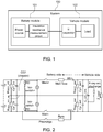
- Fig. 1 shows a block diagram of a system comprising a battery module and a vehicle module according to an embodiment of the present invention.
- a system 100 may comprise a battery module 101 and a vehicle module 102 that may be coupled with the battery module 101.
- the battery module 101 may comprise, among others, a power source and an isolation monitoring circuit coupled with the power source.
- the vehicle module 102 may comprise, among others, a Y-capacitor module comprising one or more Y-capacitors, and optionally a load that may be coupled with the Y-capacitor module.
- the Y-capacitor module and the load may be connected in parallel between HV poles HV+ and HV- of the vehicle module 102.
- each Y-capacitor may be a parasitic and/or discrete capacitor between HV-life parts and chassis/LV-Ground.
- HV poles HV+ and HV- may be connected to the load on the vehicle side.
- the isolation monitoring circuit of the battery module 101 may be coupled with the Y-capacitor module so that discharge of the Y-capacitor module can be performed on battery side by using the isolation monitoring circuit of the battery module 101.
- a corresponding circuit unit can be arranged in the isolation monitoring circuit, which may comprises at least a switch and a resistor connected in series with each other.
- the circuit unit corresponding to a Y-capacitor may further include a main contactor/relay connected in series with the switch and the resistor that may galvanically separate the cells from corresponding HV pole.
- Fig. 2 shows a circuit for implementing the block diagram of the system comprising a battery module and a vehicle module according to Fig. 1 .
- two Y-capacitors are arranged between the HV poles HV+ and HV- of the vehicle module 102.
- a first Y-capacitor of the two Y-capacitors is arranged between a first HV pole HV+ and the chassis/LV-Ground, and a second Y-capacitor of the two Y-capacitors is arranged between a second HV pole HV- and the chassis/LV-Ground.
- the vehicle module 102 may further include two resistors connected in parallel with the first and second Y-capacitors respectively.
- the vehicle module 102 may further include an X-capacitor and a load connected between the HV poles HV+ and HV-.
- a discharge circuit unit for discharging the X-capacitor may be connected in parallel with the X-capacitor, which may comprise a switch and a resistor connected in series with each other.
- the chassis is either of the vehicle module 102 or the battery module 101, or both of the vehicle module 102 and the battery module 101 and are connected.
- a Y-capacitor and/or an X-capacitor has an energy content exceeding a predefined threshold, e.g., 0.2J, a discharging operation is needed.
- a first circuit unit of the two circuit units may comprise a first resistor and a first switch connected between the positive terminal of the power source and the chassis.
- the first circuit unit may further comprise a first main relay Main+ connected in series with the first resistor and the first switch.
- the first circuit unit may be connected in parallel with the first Y-capacitor so as to discharge the first Y-capacitor.
- a second circuit unit of the two circuit units may comprise a second resistor and a second switch connected between the negative terminal of the power source and the chassis.
- the second circuit unit may further comprise a second main relay Main- connected in series with the second resistor and the second switch.
- the second circuit unit may be connected in parallel with the second Y-capacitor so as to discharge the second Y-capacitor.
- the main relays Main+ and Main- may be configured to be opened in abnormal situations, e.g. in response to a crash signal.
- a main fuse may be arranged between the first HV pole HV+ and the first main relay Main+.
- the value of the resistor R0 may be designed to measure the isolation value with an appropriate accuracy and to keep the current between HV-life parts and GND/chassis below a predetermined value, e.g. 2mA.
- the value of the resistor R0 may be high enough to discharge the Y-capacitor within a required time.
- the value of R0 may be in the same magnitude as the insulation resistance normally used between the HV poles and the chassis for discharging the Y-capacitor, e.g., several hundred k ⁇ .
- the value of R0 further depends on the operation voltage. Preferably, the value of R 0 should ensure at least 500 ⁇ /V of the operation voltage of the battery system.
- a power source may be connected between the first main relay Main+ and the second main relay Main-, for powering the vehicle module 102 though the first main relay Main+ and the second main relay Main-.
- the battery module 101 is coupled with the vehicle module 102 and both of the first main relay Main+ and the second main relay Main- are conductive (or closed)
- the positive terminal of the power source is connected with HV+ and the negative terminal of the power source is connected with HV-, and the vehicle module 102 is powered on.
- the battery module 101 is not coupled with the vehicle module 102 or either of the first main relay Main+ and the second main relay Main- is opened, the vehicle module 102 is powered off.
- two capacitors connected in series and two resistors connected in series can be connected in parallel between the positive terminal of the power source and the negative terminal of the power source, with the first one of the two capacitors and the first one of the two resistors being connected in parallel between the positive terminal of the power source and the chassis, and the second one of the two capacitors and the second one of the two resistors being connected in parallel between the negative terminal of the power source and the chassis.
- the main relays Main+ and Main- may galvanically separate the cells from the HV poles HV+, HV-.
- a precharge circuit unit may be arranged to be connected in parallel with the second main relay Main-.
- the X-capacitor may be discharged by other components.
- the battery module 101 may keep one of the relays Main+ and Main- closed (or closes the same if not already closed) and closes an isolation switch Iso-switch+ or Iso-switch- that is connected to the closed relay.
- the external Y-capacitors are discharged by the corresponding main relay Main+ or Main-, the corresponding resistor R0 and the corresponding isolation switch Iso-switch+ or Iso-switch-.
- the isolation switch connected to the corresponding relay that is open, may also be kept open.
- the invention allows to discharge both Y-capacitors by closing a chosen isolation switch and the corresponding main relay.
- the external active discharge network as shown in Fig. 2 may be used to discharge the X-capacitor.
- the battery keeps one of the relays closed (or closes them if not already closed) and closes the isolation switch that is connected to the closed relay.
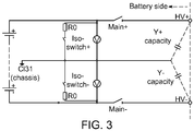
- Fig. 3 is a circuit for the battery module according to an embodiment of the present invention.
- an isolation monitoring circuit and a power source may be arranged in the battery module 101.
- Two circuit units corresponding to the two Y-capacitors may be arranged in the isolation monitoring circuit.
- a first circuit unit of two circuit units may comprise a first resistor and a first switch connected between the positive terminal of the power source and the chassis.
- the first circuit unit may further comprise a first main relay Main+ connected in series with the first resistor and the first switch.
- the first circuit unit may be connected in parallel with the first Y-capacitor so as to discharge the first Y-capacitor.
- a second circuit unit of two circuit units may comprise a second resistor and a second switch connected between the negative terminal of the power source and the chassis.
- the second circuit unit may further comprise a second main relay Main- connected in series with the second resistor and the second switch.
- the second circuit unit may be connected in parallel with the second Y-capacitor so as to discharge the second Y-capacitor.
- the main relays Main+ and Main- may be configured to be opened in abnormal situations, e.g. in response to a crash signal.
- the isolation monitoring circuit may be connected between the HV poles HV+ and HV- when the battery module 101 is coupled with the vehicle module 102.
- the first circuit unit may be connected in parallel with the first Y-capacitor so as to discharge the first Y-capacitor.
- the second circuit unit may be connected in parallel with the second Y-capacitor so as to discharge the second Y-capacitor.
- Fig. 4 is a flow chart for the method 500 according to an embodiment of the present invention.
- the main relays Main+ and Main- may be configured to be opened in abnormal situations, e.g. in response to a crash signal.
- a state of the main relays may be determined. Exemplarily, if one of the main relays is still conductive (e.g. due to a relay fault), the corresponding iso switch is set conductive (or closed) for the discharge of the Y-capacity. If both of the main relays are opened, both the main relay and the corresponding iso switch are set conductive (or closed) for the discharge of the Y-capacity.
- the method 500 may comprise the following steps.
- Step 501 receiving a crash signal if an abnormal situation occurs in a system comprising a battery module 101 and a vehicle module 102.
- the system can be the one as shown in any of Figs. 1 and 2
- the battery module 101 can be the one as shown in any of Figs. 1 to 3 .
- step 502 it is determined whether an energy content of a Y-capacitor in the vehicle module 102 is greater than a predetermined threshold in response to the crash signal. If the energy content of a Y-capacitor is greater than the predetermined threshold, the method proceeds to step 503, or if not, the method ends.
- the threshold may be 0.2J.. Alternatively, if it is set by default that active discharge is triggered, then the method proceeds to step 503 directly after step 501.
- Step 503 using the isolation monitoring circuit in the battery module 101 as a discharge device to discharge the Y-capacitor, by e.g., controlling a relay between the battery module 101 and the vehicle module 102 to connect the isolation monitoring circuit with the Y-capacitor.
- the isolation monitoring circuit in the battery module 101 as a discharge device to discharge the Y-capacitor, by e.g., controlling a relay between the battery module 101 and the vehicle module 102 to connect the isolation monitoring circuit with the Y-capacitor.
Landscapes
- Engineering & Computer Science (AREA)
- Power Engineering (AREA)
- Transportation (AREA)
- Mechanical Engineering (AREA)
- Life Sciences & Earth Sciences (AREA)
- Sustainable Development (AREA)
- Sustainable Energy (AREA)
- Electric Propulsion And Braking For Vehicles (AREA)
- Charge And Discharge Circuits For Batteries Or The Like (AREA)
- Secondary Cells (AREA)
Priority Applications (5)
| Application Number | Priority Date | Filing Date | Title |
|---|---|---|---|
| PL18201237T PL3640076T3 (pl) | 2018-10-18 | 2018-10-18 | Urządzenie i sposób rozładowania kondensatora y |
| EP18201237.7A EP3640076B1 (en) | 2018-10-18 | 2018-10-18 | Apparatus and method for discharging a y-capacitor |
| HUE18201237A HUE054619T2 (hu) | 2018-10-18 | 2018-10-18 | Berendezés és eljárás Y-kondenzátor kisütésére |
| KR1020190028231A KR102671851B1 (ko) | 2018-10-18 | 2019-03-12 | Y 커패시터 방전 방법, 및 이를 수행하는 전지 모듈 및 시스템 |
| US16/564,661 US11223213B2 (en) | 2018-10-18 | 2019-09-09 | Battery system and electric vehicle using the same |
Applications Claiming Priority (1)
| Application Number | Priority Date | Filing Date | Title |
|---|---|---|---|
| EP18201237.7A EP3640076B1 (en) | 2018-10-18 | 2018-10-18 | Apparatus and method for discharging a y-capacitor |
Publications (2)
| Publication Number | Publication Date |
|---|---|
| EP3640076A1 EP3640076A1 (en) | 2020-04-22 |
| EP3640076B1 true EP3640076B1 (en) | 2021-03-24 |
Family
ID=63914875
Family Applications (1)
| Application Number | Title | Priority Date | Filing Date |
|---|---|---|---|
| EP18201237.7A Active EP3640076B1 (en) | 2018-10-18 | 2018-10-18 | Apparatus and method for discharging a y-capacitor |
Country Status (4)
| Country | Link |
|---|---|
| EP (1) | EP3640076B1 (pl) |
| KR (1) | KR102671851B1 (pl) |
| HU (1) | HUE054619T2 (pl) |
| PL (1) | PL3640076T3 (pl) |
Cited By (1)
| Publication number | Priority date | Publication date | Assignee | Title |
|---|---|---|---|---|
| EP4116131A1 (en) * | 2021-07-09 | 2023-01-11 | Volvo Car Corporation | An energy monitoring system for discharging energy in an energy transfer device of a vehicle |
Families Citing this family (9)
| Publication number | Priority date | Publication date | Assignee | Title |
|---|---|---|---|---|
| DE102020207972A1 (de) * | 2020-06-26 | 2020-10-29 | Vitesco Technologies GmbH | Verfahren zum Entladen eines Fahrzeug-Hochvoltnetzes, Fahrzeug-Bordnetz und Isolationsüberwachungseinrichtung |
| DE102020211760A1 (de) * | 2020-09-21 | 2022-03-24 | Robert Bosch Gesellschaft mit beschränkter Haftung | Verfahren zum Entladen von Entstörkondensatoren eines ungeerdeten Energie-versorgungsnetzes |
| DE102020007243B3 (de) * | 2020-11-27 | 2022-05-05 | Daimler Ag | Verfahren zum Bestimmen zumindest eines aktuellen Kapazitätswerts einer Y-Kapazität eines Hochvolt-Bordnetzes, sowie elektronische Recheneinrichtung |
| DE102021003843B4 (de) | 2021-07-27 | 2023-03-02 | Mercedes-Benz Group AG | Isolationswächter und Verfahren zu dessen Betrieb |
| DE102021003844B4 (de) * | 2021-07-27 | 2024-12-19 | Mercedes-Benz Group AG | Bordnetz für ein Kraftfahrzeug |
| DE102022002622A1 (de) * | 2022-07-18 | 2022-09-01 | Mercedes-Benz Group AG | Fahrzeug mit einem elektrischen Bordnetz |
| DE102023002868A1 (de) | 2022-07-22 | 2024-01-25 | Mercedes-Benz Group AG | Bestimmung der Kapazitätskompatibilität zwischen Ladeinfrastruktur für Elektrofahrzeug und Elektrofahrzeug |
| CN116540117A (zh) * | 2023-03-24 | 2023-08-04 | 苏州清研精准汽车科技有限公司 | 一种动力电池y电容预测系统及预测方法 |
| DE102023120777A1 (de) * | 2023-08-04 | 2025-02-06 | Bayerische Motoren Werke Aktiengesellschaft | Steuervorrichtung und Verfahren zum aktiven Abbauen einer Spannung im Hochvoltsystem |
Family Cites Families (6)
| Publication number | Priority date | Publication date | Assignee | Title |
|---|---|---|---|---|
| US7906242B2 (en) * | 2005-11-23 | 2011-03-15 | GM Global Technology Operations LLC | Active isolation system for fuel cell |
| US7564248B2 (en) * | 2007-03-12 | 2009-07-21 | Gm Global Technology Operations, Inc. | Method and apparatus for monitoring fuel cells |
| EP2570289B1 (de) * | 2011-09-16 | 2018-08-15 | Samsung SDI Co., Ltd. | Einrichtung zur Erfassung des Isolationswiderstandes eines Hochvoltbatteriesystems |
| GB2500427B (en) * | 2012-03-22 | 2014-09-24 | Jaguar Land Rover Ltd | Battery safety system |
| US9557388B2 (en) * | 2012-05-24 | 2017-01-31 | Hitachi Automotive Systems, Ltd. | Battery control device |
| CN104681773B (zh) * | 2013-11-27 | 2017-05-03 | 观致汽车有限公司 | 用于车辆的连接装置及方法 |
-
2018
- 2018-10-18 HU HUE18201237A patent/HUE054619T2/hu unknown
- 2018-10-18 EP EP18201237.7A patent/EP3640076B1/en active Active
- 2018-10-18 PL PL18201237T patent/PL3640076T3/pl unknown
-
2019
- 2019-03-12 KR KR1020190028231A patent/KR102671851B1/ko active Active
Non-Patent Citations (1)
| Title |
|---|
| None * |
Cited By (2)
| Publication number | Priority date | Publication date | Assignee | Title |
|---|---|---|---|---|
| EP4116131A1 (en) * | 2021-07-09 | 2023-01-11 | Volvo Car Corporation | An energy monitoring system for discharging energy in an energy transfer device of a vehicle |
| US12024032B2 (en) | 2021-07-09 | 2024-07-02 | Volvo Car Corporation | Energy monitoring system for discharging energy in an energy transfer device of a vehicle |
Also Published As
| Publication number | Publication date |
|---|---|
| KR20200044650A (ko) | 2020-04-29 |
| HUE054619T2 (hu) | 2021-09-28 |
| KR102671851B1 (ko) | 2024-05-31 |
| EP3640076A1 (en) | 2020-04-22 |
| PL3640076T3 (pl) | 2021-10-18 |
Similar Documents
| Publication | Publication Date | Title |
|---|---|---|
| EP3640076B1 (en) | Apparatus and method for discharging a y-capacitor | |
| KR102816659B1 (ko) | 배터리 시스템 | |
| US11223213B2 (en) | Battery system and electric vehicle using the same | |
| US11801753B2 (en) | Battery system and vehicle including the battery system | |
| US20200079232A1 (en) | Power supply system | |
| EP3620321B1 (en) | Power supply system | |
| EP3579006B1 (en) | Validation of a temperature sensor of a battery cell | |
| US11289932B2 (en) | Battery pack and electronic device including the same | |
| EP3890059B1 (en) | An electric-vehicle battery system comprising a real time clock | |
| US11476690B2 (en) | Power supply system | |
| EP3975381A1 (en) | Battery protection apparatus and battery system including the same | |
| US20230027996A1 (en) | Relay control system and battery system | |
| EP4060785B1 (en) | Battery system and vehicle including the battery system | |
| EP4089790B1 (en) | Battery cell and battery system comprising a battery cell | |
| EP3965198A1 (en) | Online measurement of anode potential for the maximization of charging power at low temperatures | |
| US11884182B2 (en) | Electric-vehicle battery system including a real time clock | |
| EP3812205A1 (en) | Power supply system | |
| EP3683087A1 (en) | Relay with temperature sensors for safety applications according to iso 26262 | |
| US11444337B2 (en) | Solid state switch driver circuit for a battery system | |
| CN118871800A (zh) | 估计装置、蓄电装置、估计方法以及程序 | |
| US20230134512A1 (en) | Energy storage apparatus | |
| US12580233B2 (en) | Battery system and method for operating the same | |
| US20240356356A1 (en) | Charging control method, and charging control device and battery pack performing the same | |
| EP4186746A1 (en) | Battery system and method for operating the same | |
| EP3708403B1 (en) | Solid state switch driver circuit for a battery system |
Legal Events
| Date | Code | Title | Description |
|---|---|---|---|
| PUAI | Public reference made under article 153(3) epc to a published international application that has entered the european phase |
Free format text: ORIGINAL CODE: 0009012 |
|
| STAA | Information on the status of an ep patent application or granted ep patent |
Free format text: STATUS: REQUEST FOR EXAMINATION WAS MADE |
|
| 17P | Request for examination filed |
Effective date: 20190701 |
|
| AK | Designated contracting states |
Kind code of ref document: A1 Designated state(s): AL AT BE BG CH CY CZ DE DK EE ES FI FR GB GR HR HU IE IS IT LI LT LU LV MC MK MT NL NO PL PT RO RS SE SI SK SM TR |
|
| AX | Request for extension of the european patent |
Extension state: BA ME |
|
| GRAP | Despatch of communication of intention to grant a patent |
Free format text: ORIGINAL CODE: EPIDOSNIGR1 |
|
| STAA | Information on the status of an ep patent application or granted ep patent |
Free format text: STATUS: GRANT OF PATENT IS INTENDED |
|
| INTG | Intention to grant announced |
Effective date: 20201221 |
|
| GRAS | Grant fee paid |
Free format text: ORIGINAL CODE: EPIDOSNIGR3 |
|
| GRAA | (expected) grant |
Free format text: ORIGINAL CODE: 0009210 |
|
| STAA | Information on the status of an ep patent application or granted ep patent |
Free format text: STATUS: THE PATENT HAS BEEN GRANTED |
|
| AK | Designated contracting states |
Kind code of ref document: B1 Designated state(s): AL AT BE BG CH CY CZ DE DK EE ES FI FR GB GR HR HU IE IS IT LI LT LU LV MC MK MT NL NO PL PT RO RS SE SI SK SM TR |
|
| REG | Reference to a national code |
Ref country code: GB Ref legal event code: FG4D |
|
| REG | Reference to a national code |
Ref country code: CH Ref legal event code: EP |
|
| REG | Reference to a national code |
Ref country code: IE Ref legal event code: FG4D |
|
| REG | Reference to a national code |
Ref country code: AT Ref legal event code: REF Ref document number: 1374143 Country of ref document: AT Kind code of ref document: T Effective date: 20210415 Ref country code: DE Ref legal event code: R096 Ref document number: 602018014307 Country of ref document: DE |
|
| REG | Reference to a national code |
Ref country code: LT Ref legal event code: MG9D |
|
| PG25 | Lapsed in a contracting state [announced via postgrant information from national office to epo] |
Ref country code: BG Free format text: LAPSE BECAUSE OF FAILURE TO SUBMIT A TRANSLATION OF THE DESCRIPTION OR TO PAY THE FEE WITHIN THE PRESCRIBED TIME-LIMIT Effective date: 20210624 Ref country code: FI Free format text: LAPSE BECAUSE OF FAILURE TO SUBMIT A TRANSLATION OF THE DESCRIPTION OR TO PAY THE FEE WITHIN THE PRESCRIBED TIME-LIMIT Effective date: 20210324 Ref country code: GR Free format text: LAPSE BECAUSE OF FAILURE TO SUBMIT A TRANSLATION OF THE DESCRIPTION OR TO PAY THE FEE WITHIN THE PRESCRIBED TIME-LIMIT Effective date: 20210625 Ref country code: HR Free format text: LAPSE BECAUSE OF FAILURE TO SUBMIT A TRANSLATION OF THE DESCRIPTION OR TO PAY THE FEE WITHIN THE PRESCRIBED TIME-LIMIT Effective date: 20210324 Ref country code: NO Free format text: LAPSE BECAUSE OF FAILURE TO SUBMIT A TRANSLATION OF THE DESCRIPTION OR TO PAY THE FEE WITHIN THE PRESCRIBED TIME-LIMIT Effective date: 20210624 |
|
| PG25 | Lapsed in a contracting state [announced via postgrant information from national office to epo] |
Ref country code: RS Free format text: LAPSE BECAUSE OF FAILURE TO SUBMIT A TRANSLATION OF THE DESCRIPTION OR TO PAY THE FEE WITHIN THE PRESCRIBED TIME-LIMIT Effective date: 20210324 Ref country code: LV Free format text: LAPSE BECAUSE OF FAILURE TO SUBMIT A TRANSLATION OF THE DESCRIPTION OR TO PAY THE FEE WITHIN THE PRESCRIBED TIME-LIMIT Effective date: 20210324 Ref country code: SE Free format text: LAPSE BECAUSE OF FAILURE TO SUBMIT A TRANSLATION OF THE DESCRIPTION OR TO PAY THE FEE WITHIN THE PRESCRIBED TIME-LIMIT Effective date: 20210324 |
|
| REG | Reference to a national code |
Ref country code: NL Ref legal event code: MP Effective date: 20210324 |
|
| REG | Reference to a national code |
Ref country code: AT Ref legal event code: MK05 Ref document number: 1374143 Country of ref document: AT Kind code of ref document: T Effective date: 20210324 |
|
| REG | Reference to a national code |
Ref country code: HU Ref legal event code: AG4A Ref document number: E054619 Country of ref document: HU |
|
| PG25 | Lapsed in a contracting state [announced via postgrant information from national office to epo] |
Ref country code: NL Free format text: LAPSE BECAUSE OF FAILURE TO SUBMIT A TRANSLATION OF THE DESCRIPTION OR TO PAY THE FEE WITHIN THE PRESCRIBED TIME-LIMIT Effective date: 20210324 |
|
| PG25 | Lapsed in a contracting state [announced via postgrant information from national office to epo] |
Ref country code: LT Free format text: LAPSE BECAUSE OF FAILURE TO SUBMIT A TRANSLATION OF THE DESCRIPTION OR TO PAY THE FEE WITHIN THE PRESCRIBED TIME-LIMIT Effective date: 20210324 Ref country code: EE Free format text: LAPSE BECAUSE OF FAILURE TO SUBMIT A TRANSLATION OF THE DESCRIPTION OR TO PAY THE FEE WITHIN THE PRESCRIBED TIME-LIMIT Effective date: 20210324 Ref country code: CZ Free format text: LAPSE BECAUSE OF FAILURE TO SUBMIT A TRANSLATION OF THE DESCRIPTION OR TO PAY THE FEE WITHIN THE PRESCRIBED TIME-LIMIT Effective date: 20210324 Ref country code: AT Free format text: LAPSE BECAUSE OF FAILURE TO SUBMIT A TRANSLATION OF THE DESCRIPTION OR TO PAY THE FEE WITHIN THE PRESCRIBED TIME-LIMIT Effective date: 20210324 Ref country code: SM Free format text: LAPSE BECAUSE OF FAILURE TO SUBMIT A TRANSLATION OF THE DESCRIPTION OR TO PAY THE FEE WITHIN THE PRESCRIBED TIME-LIMIT Effective date: 20210324 |
|
| PG25 | Lapsed in a contracting state [announced via postgrant information from national office to epo] |
Ref country code: IS Free format text: LAPSE BECAUSE OF FAILURE TO SUBMIT A TRANSLATION OF THE DESCRIPTION OR TO PAY THE FEE WITHIN THE PRESCRIBED TIME-LIMIT Effective date: 20210724 Ref country code: PT Free format text: LAPSE BECAUSE OF FAILURE TO SUBMIT A TRANSLATION OF THE DESCRIPTION OR TO PAY THE FEE WITHIN THE PRESCRIBED TIME-LIMIT Effective date: 20210726 Ref country code: SK Free format text: LAPSE BECAUSE OF FAILURE TO SUBMIT A TRANSLATION OF THE DESCRIPTION OR TO PAY THE FEE WITHIN THE PRESCRIBED TIME-LIMIT Effective date: 20210324 Ref country code: RO Free format text: LAPSE BECAUSE OF FAILURE TO SUBMIT A TRANSLATION OF THE DESCRIPTION OR TO PAY THE FEE WITHIN THE PRESCRIBED TIME-LIMIT Effective date: 20210324 |
|
| REG | Reference to a national code |
Ref country code: DE Ref legal event code: R097 Ref document number: 602018014307 Country of ref document: DE |
|
| PG25 | Lapsed in a contracting state [announced via postgrant information from national office to epo] |
Ref country code: ES Free format text: LAPSE BECAUSE OF FAILURE TO SUBMIT A TRANSLATION OF THE DESCRIPTION OR TO PAY THE FEE WITHIN THE PRESCRIBED TIME-LIMIT Effective date: 20210324 Ref country code: AL Free format text: LAPSE BECAUSE OF FAILURE TO SUBMIT A TRANSLATION OF THE DESCRIPTION OR TO PAY THE FEE WITHIN THE PRESCRIBED TIME-LIMIT Effective date: 20210324 Ref country code: DK Free format text: LAPSE BECAUSE OF FAILURE TO SUBMIT A TRANSLATION OF THE DESCRIPTION OR TO PAY THE FEE WITHIN THE PRESCRIBED TIME-LIMIT Effective date: 20210324 |
|
| PLBE | No opposition filed within time limit |
Free format text: ORIGINAL CODE: 0009261 |
|
| STAA | Information on the status of an ep patent application or granted ep patent |
Free format text: STATUS: NO OPPOSITION FILED WITHIN TIME LIMIT |
|
| PG25 | Lapsed in a contracting state [announced via postgrant information from national office to epo] |
Ref country code: SI Free format text: LAPSE BECAUSE OF FAILURE TO SUBMIT A TRANSLATION OF THE DESCRIPTION OR TO PAY THE FEE WITHIN THE PRESCRIBED TIME-LIMIT Effective date: 20210324 |
|
| 26N | No opposition filed |
Effective date: 20220104 |
|
| REG | Reference to a national code |
Ref country code: CH Ref legal event code: PL |
|
| PG25 | Lapsed in a contracting state [announced via postgrant information from national office to epo] |
Ref country code: IS Free format text: LAPSE BECAUSE OF FAILURE TO SUBMIT A TRANSLATION OF THE DESCRIPTION OR TO PAY THE FEE WITHIN THE PRESCRIBED TIME-LIMIT Effective date: 20210724 |
|
| REG | Reference to a national code |
Ref country code: BE Ref legal event code: MM Effective date: 20211031 |
|
| PG25 | Lapsed in a contracting state [announced via postgrant information from national office to epo] |
Ref country code: MC Free format text: LAPSE BECAUSE OF FAILURE TO SUBMIT A TRANSLATION OF THE DESCRIPTION OR TO PAY THE FEE WITHIN THE PRESCRIBED TIME-LIMIT Effective date: 20210324 |
|
| PG25 | Lapsed in a contracting state [announced via postgrant information from national office to epo] |
Ref country code: LU Free format text: LAPSE BECAUSE OF NON-PAYMENT OF DUE FEES Effective date: 20211018 Ref country code: BE Free format text: LAPSE BECAUSE OF NON-PAYMENT OF DUE FEES Effective date: 20211031 |
|
| PG25 | Lapsed in a contracting state [announced via postgrant information from national office to epo] |
Ref country code: LI Free format text: LAPSE BECAUSE OF NON-PAYMENT OF DUE FEES Effective date: 20211031 Ref country code: CH Free format text: LAPSE BECAUSE OF NON-PAYMENT OF DUE FEES Effective date: 20211031 |
|
| PG25 | Lapsed in a contracting state [announced via postgrant information from national office to epo] |
Ref country code: IE Free format text: LAPSE BECAUSE OF NON-PAYMENT OF DUE FEES Effective date: 20211018 |
|
| PG25 | Lapsed in a contracting state [announced via postgrant information from national office to epo] |
Ref country code: IT Free format text: LAPSE BECAUSE OF FAILURE TO SUBMIT A TRANSLATION OF THE DESCRIPTION OR TO PAY THE FEE WITHIN THE PRESCRIBED TIME-LIMIT Effective date: 20210324 |
|
| PG25 | Lapsed in a contracting state [announced via postgrant information from national office to epo] |
Ref country code: CY Free format text: LAPSE BECAUSE OF FAILURE TO SUBMIT A TRANSLATION OF THE DESCRIPTION OR TO PAY THE FEE WITHIN THE PRESCRIBED TIME-LIMIT Effective date: 20210324 |
|
| P01 | Opt-out of the competence of the unified patent court (upc) registered |
Effective date: 20230528 |
|
| PG25 | Lapsed in a contracting state [announced via postgrant information from national office to epo] |
Ref country code: MK Free format text: LAPSE BECAUSE OF FAILURE TO SUBMIT A TRANSLATION OF THE DESCRIPTION OR TO PAY THE FEE WITHIN THE PRESCRIBED TIME-LIMIT Effective date: 20210324 |
|
| PG25 | Lapsed in a contracting state [announced via postgrant information from national office to epo] |
Ref country code: TR Free format text: LAPSE BECAUSE OF FAILURE TO SUBMIT A TRANSLATION OF THE DESCRIPTION OR TO PAY THE FEE WITHIN THE PRESCRIBED TIME-LIMIT Effective date: 20210324 |
|
| PG25 | Lapsed in a contracting state [announced via postgrant information from national office to epo] |
Ref country code: MT Free format text: LAPSE BECAUSE OF FAILURE TO SUBMIT A TRANSLATION OF THE DESCRIPTION OR TO PAY THE FEE WITHIN THE PRESCRIBED TIME-LIMIT Effective date: 20210324 |
|
| PGFP | Annual fee paid to national office [announced via postgrant information from national office to epo] |
Ref country code: FR Payment date: 20250930 Year of fee payment: 8 |
|
| PGFP | Annual fee paid to national office [announced via postgrant information from national office to epo] |
Ref country code: HU Payment date: 20251105 Year of fee payment: 8 |
|
| PGFP | Annual fee paid to national office [announced via postgrant information from national office to epo] |
Ref country code: DE Payment date: 20250930 Year of fee payment: 8 |
|
| PGFP | Annual fee paid to national office [announced via postgrant information from national office to epo] |
Ref country code: GB Payment date: 20251001 Year of fee payment: 8 |
|
| PGFP | Annual fee paid to national office [announced via postgrant information from national office to epo] |
Ref country code: PL Payment date: 20251014 Year of fee payment: 8 |