EP3639989A1 - Assembly apparatus and structure fabricating method - Google Patents
Assembly apparatus and structure fabricating method Download PDFInfo
- Publication number
- EP3639989A1 EP3639989A1 EP19203767.9A EP19203767A EP3639989A1 EP 3639989 A1 EP3639989 A1 EP 3639989A1 EP 19203767 A EP19203767 A EP 19203767A EP 3639989 A1 EP3639989 A1 EP 3639989A1
- Authority
- EP
- European Patent Office
- Prior art keywords
- gripping section
- contact
- section
- gripping
- connector
- Prior art date
- Legal status (The legal status is an assumption and is not a legal conclusion. Google has not performed a legal analysis and makes no representation as to the accuracy of the status listed.)
- Withdrawn
Links
Images








Classifications
-
- B—PERFORMING OPERATIONS; TRANSPORTING
- B25—HAND TOOLS; PORTABLE POWER-DRIVEN TOOLS; MANIPULATORS
- B25J—MANIPULATORS; CHAMBERS PROVIDED WITH MANIPULATION DEVICES
- B25J15/00—Gripping heads and other end effectors
- B25J15/0033—Gripping heads and other end effectors with gripping surfaces having special shapes
-
- B—PERFORMING OPERATIONS; TRANSPORTING
- B25—HAND TOOLS; PORTABLE POWER-DRIVEN TOOLS; MANIPULATORS
- B25J—MANIPULATORS; CHAMBERS PROVIDED WITH MANIPULATION DEVICES
- B25J9/00—Program-controlled manipulators
- B25J9/16—Program controls
- B25J9/1612—Program controls characterised by the hand, wrist, grip control
-
- B—PERFORMING OPERATIONS; TRANSPORTING
- B23—MACHINE TOOLS; METAL-WORKING NOT OTHERWISE PROVIDED FOR
- B23P—METAL-WORKING NOT OTHERWISE PROVIDED FOR; COMBINED OPERATIONS; UNIVERSAL MACHINE TOOLS
- B23P19/00—Machines for simply fitting together or separating metal parts or objects, or metal and non-metal parts, whether or not involving some deformation; Tools or devices therefor so far as not provided for in other classes
- B23P19/02—Machines for simply fitting together or separating metal parts or objects, or metal and non-metal parts, whether or not involving some deformation; Tools or devices therefor so far as not provided for in other classes for connecting objects by press fit or for detaching same
-
- B—PERFORMING OPERATIONS; TRANSPORTING
- B25—HAND TOOLS; PORTABLE POWER-DRIVEN TOOLS; MANIPULATORS
- B25J—MANIPULATORS; CHAMBERS PROVIDED WITH MANIPULATION DEVICES
- B25J11/00—Manipulators not otherwise provided for
- B25J11/005—Manipulators for mechanical processing tasks
-
- B—PERFORMING OPERATIONS; TRANSPORTING
- B25—HAND TOOLS; PORTABLE POWER-DRIVEN TOOLS; MANIPULATORS
- B25J—MANIPULATORS; CHAMBERS PROVIDED WITH MANIPULATION DEVICES
- B25J15/00—Gripping heads and other end effectors
- B25J15/02—Gripping heads and other end effectors servo-actuated
- B25J15/0253—Gripping heads and other end effectors servo-actuated comprising parallel grippers
-
- B—PERFORMING OPERATIONS; TRANSPORTING
- B25—HAND TOOLS; PORTABLE POWER-DRIVEN TOOLS; MANIPULATORS
- B25J—MANIPULATORS; CHAMBERS PROVIDED WITH MANIPULATION DEVICES
- B25J9/00—Program-controlled manipulators
- B25J9/16—Program controls
- B25J9/1679—Program controls characterised by the tasks executed
-
- B—PERFORMING OPERATIONS; TRANSPORTING
- B25—HAND TOOLS; PORTABLE POWER-DRIVEN TOOLS; MANIPULATORS
- B25J—MANIPULATORS; CHAMBERS PROVIDED WITH MANIPULATION DEVICES
- B25J9/00—Program-controlled manipulators
- B25J9/16—Program controls
- B25J9/1679—Program controls characterised by the tasks executed
- B25J9/1682—Dual arm manipulator; Coordination of several manipulators
-
- B—PERFORMING OPERATIONS; TRANSPORTING
- B25—HAND TOOLS; PORTABLE POWER-DRIVEN TOOLS; MANIPULATORS
- B25J—MANIPULATORS; CHAMBERS PROVIDED WITH MANIPULATION DEVICES
- B25J9/00—Program-controlled manipulators
- B25J9/16—Program controls
- B25J9/1679—Program controls characterised by the tasks executed
- B25J9/1687—Assembly, peg and hole, palletising, straight line, weaving pattern movement
-
- B—PERFORMING OPERATIONS; TRANSPORTING
- B23—MACHINE TOOLS; METAL-WORKING NOT OTHERWISE PROVIDED FOR
- B23P—METAL-WORKING NOT OTHERWISE PROVIDED FOR; COMBINED OPERATIONS; UNIVERSAL MACHINE TOOLS
- B23P19/00—Machines for simply fitting together or separating metal parts or objects, or metal and non-metal parts, whether or not involving some deformation; Tools or devices therefor so far as not provided for in other classes
- B23P19/10—Aligning parts to be fitted together
-
- B—PERFORMING OPERATIONS; TRANSPORTING
- B25—HAND TOOLS; PORTABLE POWER-DRIVEN TOOLS; MANIPULATORS
- B25J—MANIPULATORS; CHAMBERS PROVIDED WITH MANIPULATION DEVICES
- B25J15/00—Gripping heads and other end effectors
- B25J15/009—Gripping heads and other end effectors with pins for accurately positioning the object on the gripping head
-
- G—PHYSICS
- G05—CONTROLLING; REGULATING
- G05B—CONTROL OR REGULATING SYSTEMS IN GENERAL; FUNCTIONAL ELEMENTS OF SUCH SYSTEMS; MONITORING OR TESTING ARRANGEMENTS FOR SUCH SYSTEMS OR ELEMENTS
- G05B2219/00—Program-control systems
- G05B2219/30—Nc systems
- G05B2219/39—Robotics, robotics to robotics hand
- G05B2219/39109—Dual arm, multiarm manipulation, object handled in cooperation
Definitions
- the present disclosure relates to an assembly apparatus and a structure fabricating method.
- An assembly apparatus includes a force sensor for correcting positional shift.
- An assembly apparatus for assembling a first member and a second member.
- the assembly apparatus includes a first gripping section, a second gripping section, and a driving section.
- the first gripping section includes a first contact member and a first elastic member.
- the second gripping section includes a second contact member and a second elastic member.
- the driving section drives the first gripping section and the second gripping section.
- the driving section drives the first gripping section and the second gripping section such that the first contact member and the second contact member make contact with the second member.
- the first gripping section and the second gripping section grip the second member through the first elastic member urging the first contact member and the second elastic member urging the second contact member.
- the driving section drives the first gripping section and the second gripping section such that the first member and the second member are assembled.
- An assembly apparatus for assembling a plurality of members including a first member and a second member.
- the assembly apparatus includes a first gripping section, a second gripping section, and a driving section.
- the first gripping section includes a first contact member.
- the second gripping section includes a second contact member.
- the driving section drives the first gripping section and the second gripping section.
- the first gripping section and the second gripping section grip the second member through the driving section driving the first gripping section and the second gripping section such that the first contact member and the second contact member make contact with the second member.
- the first gripping section and the second gripping section grip the first member.
- the driving section drives the first gripping section and the second gripping section such that the first member and the second member are assembled.
- a structure fabricating method is a method through which a structure is fabricated by assembling a first member and a second member.
- the method includes making contact, gripping, and moving.
- a first contact member and a second contact member make contact with the second member through driving of a first gripping section and a second gripping section.
- the first gripping section includes the first contact member and a first elastic member.
- the second gripping section includes the second contact member and a second elastic member.
- the first gripping section and the second gripping section grip the second member through the first elastic member urging the first contact member and the second elastic member urging the second contact member.
- the moving the first gripping section and the second gripping section are moved such that the first member and the second member are assembled.
- a left-to-right direction is defined as a positive X-axis direction
- a front-to-back direction is defined as a positive Y-axis direction
- a bottom-to-top direction is defined as a positive Z-axis direction on the sheet surface of FIG. 1 .
- Elements that are the same or equivalent are labeled with the same reference signs in the drawings and description thereof is not repeated.
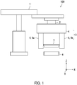
- FIG. 1 is a diagram illustrating an example of the assembly apparatus 100 according to the embodiment.
- the assembly apparatus 100 is an apparatus which fits a male second connector 7 into a female first connector 6 to install the second connector 7 in the first connector 6.
- the assembly apparatus 100 includes a robot 1, a positional shift correcting device 2, and a gripping mechanism 3.
- the first connector 6 is equivalent to an example of a "first member”
- the second connector 7 is equivalent to an example of a "second member”.
- the robot 1 causes the gripping mechanism 3 to move relative to the second connector 7, and causes the gripping mechanism 3 to move relative to the first connector 6.
- the gripping mechanism 3 includes a driving section 4, a first gripping section 5a, and a second gripping section 5b.
- the first gripping section 5a and the second gripping section 5b may be collectively referred to as a gripping section 5.
- the driving section 4 drives the gripping section 5 to adjust an interval between the first gripping section 5a and the second gripping section 5b. After gripping the second connector 7, the gripping section 5 grips the first connector 6 while gripping the second connector 7.
- the positional shift correcting device 2 detects a direction of force acting on the second connector 7 when the second connector 7 is fitted to the first connector 6 and corrects positional shift of the second connector 7 according to the direction of the acting force.
- FIG. 2 is a perspective view of the gripping section 5.
- FIG. 3 is an exploded perspective view of the first gripping section 5a.
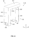
- FIG. 4 is an exploded perspective view of the second gripping section 5b.
- the first gripping section 5a and the second gripping section 5b each include a support member 51, a contact member 52, and an elastic member 53.
- the first gripping section 5a and the second gripping section 5b have the same shape and structure as each other.
- each of the support members 51 has an L-shaped main body 511.
- the L-shaped main body 511 has a horizontal portion 511h extending in the X-axis direction and a perpendicular portion 511p intersecting with the horizontal portion 511h and extending in the Z-axis direction.
- the horizontal portion 511h is driven by the driving section 4.
- the perpendicular portion 511p of one of the L-shaped main bodies 511 and the perpendicular portion 511p of the other L-shaped main body 511 are located opposite to each other in the X-axis direction.
- a screw hole 512 and a cutout portion 513 are provided in the outer surface of each of the two perpendicular portions 511p.
- the screw hole 512 is in a position near a part of the perpendicular portion 551p connecting with a horizontal portion 511h.
- the cutout portion 513 is in a position far from the connecting part.
- the screw hole 512 is used when fixing the elastic member 53. As illustrated in FIG.
- a through hole 514 and a contact portion 515 are provided on an end in the negative Z-axis direction on the inner surface of each of the two perpendicular portions 511p.
- the through hole 514 has a rectangular shape so as to accept insertion of a contact member 52.
- the cutout portion 513 communicates with the through hole 514.
- the contact portion 515 is in the form of as a recess.
- the contact member 52 is inserted into the cutout portion 513 from the outer side of a perpendicular portion 511p, reaches the inner surface of the perpendicular portion 511p through the through hole 514, and finally protrudes from the inner surface.
- An elastic member 53 has a strip-shaped leaf spring 531 and a through hole 532 provided in an upper portion of the leaf spring 531.
- the leaf spring 531 is fixed to the outer surface of the perpendicular portion 511p by a screw inserted through the through hole 532 being screwed into the screw hole 512.
- the leaf spring 531 pushes the contact member 52 toward the inner surface of the perpendicular portion 511p.
- FIG. 5A is an enlarged plan view of the contact member 52.
- the contact member 52 is a plate-shaped member and has a rectangular portion 521, two protrusions 522, and a recess 523.
- the two protrusions 522 extend outward from opposite ends of a first edge of the rectangular portion 521.
- the recess 523 is provided in the center of a second edge of the rectangular portion 521. The second edge is parallel to the first edge.
- Two chamfered portions 524 are provided in the recess 523.
- the recess 523 accepts insertion of an end of the second connector 7 in a longitudinal direction.
- the two chamfered portions 524 make contact with the end of the second connector 7 in the longitudinal direction.
- FIG. 5B illustrates a variation of the contact member 52.
- the contact member 52 of FIG. 5B differs from the contact member 52 of FIG. 5A in having a projection 525 instead of the recess 523.
- the projection 525 corresponds to a recessed shape of the end of the second connector 7 in the longitudinal direction.
- the contact member 52 of the first gripping section 5a and the contact member 52 of the second gripping section 5b may have different shapes so as to correspond to the shape of the second connector 7.
- FIG. 6 is a cross-sectional view of the support member 51 taken along a line VI-VI in FIG. 3 .
- FIG. 7 is a cross-sectional view of the support member 51 taken along a line VII-VII in FIG. 3 .
- the through hole 514 communicates with the contact portion 515 in the inner surface of the perpendicular portion 511p.
- the thickness (length in the X-axis direction) of the perpendicular portion 511p in a part above the through hole 514 is greater than the thickness (length in the X-axis direction) of the perpendicular portion 511p in a part below the through hole 514.
- the difference in thickness of the perpendicular portion 511p forms a stepped portion which functions as a stopper 516 which restricts the second connector 7 from sliding in the positive Z-axis direction.
- the stopper 516 is equivalent to an example of a "restricting portion".
- the through hole 514 communicates with the wide cutout portion 513 in the outer surface of the perpendicular portion 511p.
- the cutout portion 513 inhibits escape of the contact member 52 from the inner surface of the perpendicular portion 511p by accepting insertion of the protrusion 522 of the contact member 52.
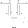
- FIG. 8 is a front view for describing the process through which the gripping section 5 grips the second connector 7.
- FIG. 9 is a partial enlarged view illustrating a state just before the gripping section 5 grips the second connector 7.
- FIG. 10 is a partial enlarged view of a state in which the gripping section 5 grips the second connector 7.
- the second connector 7 is fixed above a position determining member 8.
- the robot 1 illustrated in FIG. 1 causes the first gripping section 5a and the second gripping section 5b to descend toward the second connector 7 in a state in which the driving section 4 has widened the interval between the first gripping section 5a and the second gripping section 5b.
- the robot 1 suspends the descent of the first gripping section 5a and the second gripping section 5b when the height of the contact members 52 matches the height of an upper edge of the second connector 7. Thereafter, the driving section 4 narrows the interval between the first gripping section 5a and the second gripping section 5b.
- the two contact members 52 make contact with the second connector 7 from both sides of the second connector 7 just before the first gripping section 5a and the second gripping section 5b grip the second connector 7.
- the two chamfered portions 524 illustrated in FIG. 5A make contact with the end of the second connector 7 in the longitudinal direction.
- the two chamfered portions 524 serve to adjust positional shift.
- the driving section 4 further narrows the interval between the first gripping section 5a and the second gripping section 5b.
- the elastic members 53 receive force from the second connector 7 through the contact members 52 and bend.
- the second connector 7 receives force from the two elastic members 53 through the contact members 52 and is gripped. That is, in a first position of the first gripping section 5a and the second gripping section 5b illustrated in FIG. 10 , the first gripping section 5a and the second gripping section 5b grip the second connector 7.
- the first position is a position in which the first gripping section 5a and the second gripping section 5b initially grip the second connector 7.
- the spring strength of the two elastic members 53 is equal. Accordingly, in the first position of the first gripping section 5a and the second gripping section 5b, the two elastic members 53 exhibit an equal amount of elastic deformation. As a result, the center of the second connector 7 in the longitudinal direction matches the center between the first gripping section 5a and the second gripping section 5b.
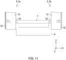
- FIG. 11 is a partial enlarged view of a state just before the gripping section 5 grips the first connector 6.
- FIG. 12 is a partial enlarged view illustrating a state in which the gripping section 5 grips the first connector 6.
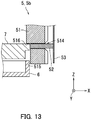
- FIG. 13 is a vertical cross-sectional view of the second gripping section 5b in FIG. 12 .
- the robot 1 causes the first gripping section 5a and the second gripping section 5b to descend toward the first connector 6 in a state in which the driving section 4 keeps the first gripping section 5a and the second gripping section 5b in the first position.
- the robot 1 suspends the descent of the first gripping section 5a and the second gripping section 5b when lower edges of the support members 51 have become lower than an upper edge of the first connector 6.
- the first connector 6 is restricted from moving by an unillustrated member.
- FIG. 11 illustrates a state when the descent of the first gripping section 5a and the second gripping section 5b is suspended, that is, a state just before the first gripping section 5a and the second gripping section 5b grip the first connector 6.
- the driving section 4 further narrows the interval between the first gripping section 5a and the second gripping section 5b.
- the first gripping section 5a and the second gripping section 5b reach a second position illustrated in FIGS. 12 and 13 .
- the second position is a position in which the first gripping section 5a and the second gripping section 5b grip the first connector 6.
- the two support members 51 grip the first connector 6 from both sides in the second position of the first gripping section 5a and the second gripping section 5b.
- the two contact portions 515 grip the first connector 6 from both ends in the longitudinal direction.
- the elastic members 53 bend farther than in the first position.
- the contact members 52 recede farther than in the first position.
- an upper surface of an end of the second connector 7 gripped by the contact members 52 advances into the support members 51 until reaching the bottom of the stoppers 516.
- the two elastic members 53 exhibit an equal amount of elastic deformation.
- the center of the second connector 7 in the longitudinal direction matches the center between the first gripping section 5a and the second gripping section 5b.
- the center of the first connector 6 in the longitudinal direction also matches the center between the first gripping section 5a and the second gripping section 5b. That is, the center of the first connector 6 in the longitudinal direction matches the center of the second connector 7 in the longitudinal direction.
- the robot 1 causes the first gripping section 5a and the second gripping section 5b to further descend in a state in which the driving section 4 keeps the first gripping section 5a and the second gripping section 5b in the second position.
- the first connector 6 is restricted from moving.
- the support members 51 and the second connector 7 descend together and the second connector 7 is inserted into the first connector 6 after the upper surface of the end of the second connector 7 has made contact with the stoppers 516.
- the stoppers 516 restrict the second connector 7 from sliding in a direction which is opposite to a direction in which the second connector 7 is fitted in the first connector 6, and the first connector 6 slides on the contact portions 515. As such, the second connector 7 is fitted to the first connector 6.
- FIG. 14 is a flowchart depicting an example of the structure fabricating method according to the embodiment.
- the structure fabricating method according to the embodiment is a method through which a structure is fabricated by assembling the first connector 6 and the second connector 7, and includes a contact process S1, a gripping process S3, and a movement process S5.
- the first and second gripping sections 5a and 5b including the contact members 52 and the elastic members 53 are driven.
- the contact members 52 of the first and second gripping sections 5a and 5b make contact with the second connector 7.
- the first and second gripping sections 5a and 5b grip the second connector 7 through the elastic members 53 of the first and second gripping sections 5a and 5b urging the contact members 52.
- the first and second gripping sections 5a and 5b are moved such that the first connector 6 and the second connector 7 are assembled.
- the first connector 6 and the second connector 7 can be assembled at low cost.
Landscapes
- Engineering & Computer Science (AREA)
- Mechanical Engineering (AREA)
- Robotics (AREA)
- Health & Medical Sciences (AREA)
- General Health & Medical Sciences (AREA)
- Orthopedic Medicine & Surgery (AREA)
- Automatic Assembly (AREA)
- Manipulator (AREA)
Abstract
Description
- The present disclosure relates to an assembly apparatus and a structure fabricating method.
- An assembly apparatus includes a force sensor for correcting positional shift.
- An assembly apparatus according to an aspect of the present disclosure is for assembling a first member and a second member. The assembly apparatus includes a first gripping section, a second gripping section, and a driving section. The first gripping section includes a first contact member and a first elastic member. The second gripping section includes a second contact member and a second elastic member. The driving section drives the first gripping section and the second gripping section. The driving section drives the first gripping section and the second gripping section such that the first contact member and the second contact member make contact with the second member. The first gripping section and the second gripping section grip the second member through the first elastic member urging the first contact member and the second elastic member urging the second contact member. The driving section drives the first gripping section and the second gripping section such that the first member and the second member are assembled.
- An assembly apparatus according to another aspect of the present disclosure is for assembling a plurality of members including a first member and a second member. The assembly apparatus includes a first gripping section, a second gripping section, and a driving section. The first gripping section includes a first contact member. The second gripping section includes a second contact member. The driving section drives the first gripping section and the second gripping section. The first gripping section and the second gripping section grip the second member through the driving section driving the first gripping section and the second gripping section such that the first contact member and the second contact member make contact with the second member. The first gripping section and the second gripping section grip the first member. The driving section drives the first gripping section and the second gripping section such that the first member and the second member are assembled.
- A structure fabricating method according to an aspect of the present disclosure is a method through which a structure is fabricated by assembling a first member and a second member. The method includes making contact, gripping, and moving. In the making contact, a first contact member and a second contact member make contact with the second member through driving of a first gripping section and a second gripping section. The first gripping section includes the first contact member and a first elastic member. The second gripping section includes the second contact member and a second elastic member. In the gripping, the first gripping section and the second gripping section grip the second member through the first elastic member urging the first contact member and the second elastic member urging the second contact member. In the moving, the first gripping section and the second gripping section are moved such that the first member and the second member are assembled.
-
-
FIG. 1 is a diagram illustrating an example of an assembly apparatus according to an embodiment of the present disclosure. -
FIG. 2 is a perspective view of a first gripping section and a second gripping section. -
FIG. 3 is an exploded perspective view of the first gripping section. -
FIG. 4 is an exploded perspective view of the second gripping section. -
FIGS. 5A and 5B are enlarged plan views of a contact member. -
FIG. 6 is a cross-sectional view of a support member taken along a line VI-VI inFIG. 3 . -
FIG. 7 is a cross-sectional view of the support member taken along a line VII-VII inFIG. 3 . -
FIG. 8 is a front view for describing a process of gripping a second connector. -
FIG. 9 is a partial enlarged view for describing the process of gripping the second connector. -
FIG. 10 is a partial enlarged view for describing the process of gripping the second connector. -
FIG. 11 is a partial enlarged view for describing a process of gripping a first connector. -
FIG. 12 is a partial enlarged view for describing the process of gripping the first connector. -
FIG. 13 is a vertical cross-sectional view of the second gripping section inFIG. 12 . -
FIG. 14 is a flowchart depicting an example of a structure fabricating method according to the embodiment of the present disclosure. - The following describes an embodiment of the present disclosure with reference to
FIGS. 1 to 14 . For convenience, a left-to-right direction is defined as a positive X-axis direction, a front-to-back direction is defined as a positive Y-axis direction, and a bottom-to-top direction is defined as a positive Z-axis direction on the sheet surface ofFIG. 1 . Elements that are the same or equivalent are labeled with the same reference signs in the drawings and description thereof is not repeated. - First, an
assembly apparatus 100 according to the embodiment is described with reference toFIG. 1. FIG. 1 is a diagram illustrating an example of theassembly apparatus 100 according to the embodiment. - As illustrated in
FIG. 1 , theassembly apparatus 100 is an apparatus which fits a malesecond connector 7 into a femalefirst connector 6 to install thesecond connector 7 in thefirst connector 6. Theassembly apparatus 100 includes arobot 1, a positionalshift correcting device 2, and agripping mechanism 3. Thefirst connector 6 is equivalent to an example of a "first member" and thesecond connector 7 is equivalent to an example of a "second member". - The
robot 1 causes thegripping mechanism 3 to move relative to thesecond connector 7, and causes thegripping mechanism 3 to move relative to thefirst connector 6. - The
gripping mechanism 3 includes adriving section 4, afirst gripping section 5a, and a second gripping section 5b. In the following description, thefirst gripping section 5a and the second gripping section 5b may be collectively referred to as agripping section 5. - The
driving section 4 drives thegripping section 5 to adjust an interval between thefirst gripping section 5a and the second gripping section 5b. After gripping thesecond connector 7, thegripping section 5 grips thefirst connector 6 while gripping thesecond connector 7. - The positional
shift correcting device 2 detects a direction of force acting on thesecond connector 7 when thesecond connector 7 is fitted to thefirst connector 6 and corrects positional shift of thesecond connector 7 according to the direction of the acting force. - Next, the
gripping section 5 according to the embodiment is described with reference toFIGS. 2 to 4 .FIG. 2 is a perspective view of thegripping section 5.FIG. 3 is an exploded perspective view of thefirst gripping section 5a.FIG. 4 is an exploded perspective view of the second gripping section 5b. - As illustrated in
FIG. 2 , thefirst gripping section 5a and the second gripping section 5b each include asupport member 51, acontact member 52, and anelastic member 53. Thefirst gripping section 5a and the second gripping section 5b have the same shape and structure as each other. - As illustrated in
FIGS. 3 and4 , each of thesupport members 51 has an L-shapedmain body 511. The L-shapedmain body 511 has ahorizontal portion 511h extending in the X-axis direction and aperpendicular portion 511p intersecting with thehorizontal portion 511h and extending in the Z-axis direction. Thehorizontal portion 511h is driven by thedriving section 4. - The
perpendicular portion 511p of one of the L-shapedmain bodies 511 and theperpendicular portion 511p of the other L-shapedmain body 511 are located opposite to each other in the X-axis direction. As illustrated inFIG. 3 , ascrew hole 512 and acutout portion 513 are provided in the outer surface of each of the twoperpendicular portions 511p. Thescrew hole 512 is in a position near a part of the perpendicular portion 551p connecting with ahorizontal portion 511h. Thecutout portion 513 is in a position far from the connecting part. Thescrew hole 512 is used when fixing theelastic member 53. As illustrated inFIG. 4 , a throughhole 514 and acontact portion 515 are provided on an end in the negative Z-axis direction on the inner surface of each of the twoperpendicular portions 511p. The throughhole 514 has a rectangular shape so as to accept insertion of acontact member 52. Thecutout portion 513 communicates with the throughhole 514. Thecontact portion 515 is in the form of as a recess. - The
contact member 52 is inserted into thecutout portion 513 from the outer side of aperpendicular portion 511p, reaches the inner surface of theperpendicular portion 511p through the throughhole 514, and finally protrudes from the inner surface. - An
elastic member 53 has a strip-shapedleaf spring 531 and a throughhole 532 provided in an upper portion of theleaf spring 531. Theleaf spring 531 is fixed to the outer surface of theperpendicular portion 511p by a screw inserted through the throughhole 532 being screwed into thescrew hole 512. Theleaf spring 531 pushes thecontact member 52 toward the inner surface of theperpendicular portion 511p. - Next, a
contact member 52 is described with reference toFIGS. 5A and 5B. FIG. 5A is an enlarged plan view of thecontact member 52. - As illustrated in
FIG. 5A , thecontact member 52 is a plate-shaped member and has arectangular portion 521, twoprotrusions 522, and arecess 523. The twoprotrusions 522 extend outward from opposite ends of a first edge of therectangular portion 521. Therecess 523 is provided in the center of a second edge of therectangular portion 521. The second edge is parallel to the first edge. Two chamferedportions 524 are provided in therecess 523. Therecess 523 accepts insertion of an end of thesecond connector 7 in a longitudinal direction. The two chamferedportions 524 make contact with the end of thesecond connector 7 in the longitudinal direction. -
FIG. 5B illustrates a variation of thecontact member 52. Thecontact member 52 ofFIG. 5B differs from thecontact member 52 ofFIG. 5A in having aprojection 525 instead of therecess 523. Theprojection 525 corresponds to a recessed shape of the end of thesecond connector 7 in the longitudinal direction. Thecontact member 52 of the firstgripping section 5a and thecontact member 52 of the second gripping section 5b may have different shapes so as to correspond to the shape of thesecond connector 7. - Next, a
support member 51 is described with reference toFIGS. 6 and 7. FIG. 6 is a cross-sectional view of thesupport member 51 taken along a line VI-VI inFIG. 3 .FIG. 7 is a cross-sectional view of thesupport member 51 taken along a line VII-VII inFIG. 3 . - As illustrated in
FIG. 6 , the throughhole 514 communicates with thecontact portion 515 in the inner surface of theperpendicular portion 511p. The thickness (length in the X-axis direction) of theperpendicular portion 511p in a part above the throughhole 514 is greater than the thickness (length in the X-axis direction) of theperpendicular portion 511p in a part below the throughhole 514. The difference in thickness of theperpendicular portion 511p forms a stepped portion which functions as astopper 516 which restricts thesecond connector 7 from sliding in the positive Z-axis direction. Thestopper 516 is equivalent to an example of a "restricting portion". - As illustrated in
FIG. 7 , the throughhole 514 communicates with thewide cutout portion 513 in the outer surface of theperpendicular portion 511p. Thecutout portion 513 inhibits escape of thecontact member 52 from the inner surface of theperpendicular portion 511p by accepting insertion of theprotrusion 522 of thecontact member 52. - Next, operation of the
assembly apparatus 100 is described with reference toFIGS. 8 to 13 . - First, a process of gripping the
second connector 7 is described with reference toFIGS. 8 to 10 .FIG. 8 is a front view for describing the process through which thegripping section 5 grips thesecond connector 7.FIG. 9 is a partial enlarged view illustrating a state just before thegripping section 5 grips thesecond connector 7.FIG. 10 is a partial enlarged view of a state in which thegripping section 5 grips thesecond connector 7. - As illustrated in
FIG. 8 , thesecond connector 7 is fixed above aposition determining member 8. Therobot 1 illustrated inFIG. 1 causes the firstgripping section 5a and the second gripping section 5b to descend toward thesecond connector 7 in a state in which thedriving section 4 has widened the interval between the firstgripping section 5a and the second gripping section 5b. Therobot 1 suspends the descent of the firstgripping section 5a and the second gripping section 5b when the height of thecontact members 52 matches the height of an upper edge of thesecond connector 7. Thereafter, thedriving section 4 narrows the interval between the firstgripping section 5a and the second gripping section 5b. - As illustrated in
FIG. 9 , the twocontact members 52 make contact with thesecond connector 7 from both sides of thesecond connector 7 just before the firstgripping section 5a and the second gripping section 5b grip thesecond connector 7. Specifically the two chamferedportions 524 illustrated inFIG. 5A make contact with the end of thesecond connector 7 in the longitudinal direction. The two chamferedportions 524 serve to adjust positional shift. - As illustrated in
FIG. 10 , thedriving section 4 further narrows the interval between the firstgripping section 5a and the second gripping section 5b. Theelastic members 53 receive force from thesecond connector 7 through thecontact members 52 and bend. As a result, thesecond connector 7 receives force from the twoelastic members 53 through thecontact members 52 and is gripped. That is, in a first position of the firstgripping section 5a and the second gripping section 5b illustrated inFIG. 10 , the firstgripping section 5a and the second gripping section 5b grip thesecond connector 7. The first position is a position in which the firstgripping section 5a and the second gripping section 5b initially grip thesecond connector 7. - The spring strength of the two
elastic members 53 is equal. Accordingly, in the first position of the firstgripping section 5a and the second gripping section 5b, the twoelastic members 53 exhibit an equal amount of elastic deformation. As a result, the center of thesecond connector 7 in the longitudinal direction matches the center between the firstgripping section 5a and the second gripping section 5b. - Next, a process of gripping the
first connector 6 is further described with reference toFIGS. 1 and11 to 13 .FIG. 11 is a partial enlarged view of a state just before thegripping section 5 grips thefirst connector 6.FIG. 12 is a partial enlarged view illustrating a state in which thegripping section 5 grips thefirst connector 6.FIG. 13 is a vertical cross-sectional view of the second gripping section 5b inFIG. 12 . - As illustrated in
FIG. 11 , therobot 1 causes the firstgripping section 5a and the second gripping section 5b to descend toward thefirst connector 6 in a state in which thedriving section 4 keeps the firstgripping section 5a and the second gripping section 5b in the first position. Therobot 1 suspends the descent of the firstgripping section 5a and the second gripping section 5b when lower edges of thesupport members 51 have become lower than an upper edge of thefirst connector 6. Thefirst connector 6 is restricted from moving by an unillustrated member. -
FIG. 11 illustrates a state when the descent of the firstgripping section 5a and the second gripping section 5b is suspended, that is, a state just before the firstgripping section 5a and the second gripping section 5b grip thefirst connector 6. Thereafter, thedriving section 4 further narrows the interval between the firstgripping section 5a and the second gripping section 5b. As a result, the firstgripping section 5a and the second gripping section 5b reach a second position illustrated inFIGS. 12 and13 . The second position is a position in which the firstgripping section 5a and the second gripping section 5b grip thefirst connector 6. - As illustrated in
FIGS. 12 and13 , the twosupport members 51 grip thefirst connector 6 from both sides in the second position of the firstgripping section 5a and the second gripping section 5b. Specifically, the twocontact portions 515 grip thefirst connector 6 from both ends in the longitudinal direction. Theelastic members 53 bend farther than in the first position. Also, thecontact members 52 recede farther than in the first position. As a result, as illustrated inFIG. 13 , an upper surface of an end of thesecond connector 7 gripped by thecontact members 52 advances into thesupport members 51 until reaching the bottom of thestoppers 516. - In the second position of the first
gripping section 5a and the second gripping section 5b, the twoelastic members 53 exhibit an equal amount of elastic deformation. As a result, the center of thesecond connector 7 in the longitudinal direction matches the center between the firstgripping section 5a and the second gripping section 5b. By contrast, the center of thefirst connector 6 in the longitudinal direction also matches the center between the firstgripping section 5a and the second gripping section 5b. That is, the center of thefirst connector 6 in the longitudinal direction matches the center of thesecond connector 7 in the longitudinal direction. - The
robot 1 causes the firstgripping section 5a and the second gripping section 5b to further descend in a state in which thedriving section 4 keeps the firstgripping section 5a and the second gripping section 5b in the second position. By contrast, thefirst connector 6 is restricted from moving. As a result, thesupport members 51 and thesecond connector 7 descend together and thesecond connector 7 is inserted into thefirst connector 6 after the upper surface of the end of thesecond connector 7 has made contact with thestoppers 516. Meanwhile, thestoppers 516 restrict thesecond connector 7 from sliding in a direction which is opposite to a direction in which thesecond connector 7 is fitted in thefirst connector 6, and thefirst connector 6 slides on thecontact portions 515. As such, thesecond connector 7 is fitted to thefirst connector 6. - Finally, a structure fabricating method according to the embodiment is described with reference to
FIG. 14. FIG. 14 is a flowchart depicting an example of the structure fabricating method according to the embodiment. - As illustrated in
FIG. 14 , the structure fabricating method according to the embodiment is a method through which a structure is fabricated by assembling thefirst connector 6 and thesecond connector 7, and includes a contact process S1, a gripping process S3, and a movement process S5. - In the contact process S1, the first and second
gripping sections 5a and 5b including thecontact members 52 and theelastic members 53 are driven. As a result, thecontact members 52 of the first and secondgripping sections 5a and 5b make contact with thesecond connector 7. - In the gripping process S3, the first and second
gripping sections 5a and 5b grip thesecond connector 7 through theelastic members 53 of the first and secondgripping sections 5a and 5b urging thecontact members 52. - In the movement process S5, the first and second
gripping sections 5a and 5b are moved such that thefirst connector 6 and thesecond connector 7 are assembled. - According to the
assembly apparatus 100 and the structure fabricating method of the embodiment, thefirst connector 6 and thesecond connector 7 can be assembled at low cost. - The above description is of an ideal embodiment of the present disclosure, and may thus contain various favorable technical limitations. However, the technical scope of the present disclosure is not limited to these aspects unless specific limitations to the present disclosure are noted. That is, elements of configuration in the above embodiment may be appropriately replaced with existing elements of configuration and the like, and a number of variations including combinations with other existing elements of configuration are possible. The description of the above embodiment does not limit the content of the disclosure recited in the scope of the claims.
- (1) As described with reference to
FIG. 1 , the operational result of theassembly apparatus 100 is "fitting" of a connector in the embodiment of the present disclosure. However, the present disclosure is not limited as such. For example, other operational results such as "engagement" or "installation" may be achieved. - (2) As described with reference to
FIG. 1 , the "member" which is a subject of assembly is a "connector" in the embodiment of the present disclosure. However, the present disclosure is not limited as such. For example, a "machine component such as a screw" or an "electronic component as a generic concept" may be a subject of assembly. - (3) As described with reference to
FIG. 12 , the number of members which perform simultaneous gripping is two in the embodiment of the present disclosure. However, the present disclosure is not limited as such. The number of members which perform simultaneous gripping may be three or more. - (4) As described with reference to
FIGS. 3 and4 , the firstgripping section 5a and the second gripping section 5b each include theelastic member 53 in the embodiment of the present disclosure. However, the present disclosure is not limited as such. A configuration not including theelastic member 53 is also possible in order to simultaneously grip a plurality of members.
Claims (10)
- An assembly apparatus for assembling a first member (6) and a second member (7), the assembly apparatus comprising:a first gripping section (5a) including a first contact member (52) and a first elastic member (53);a second gripping section (5b) including a second contact member (52) and a second elastic member (53); anda driving section (4) configured to drive the first gripping section and the second gripping section, whereinthe driving section drives the first gripping section and the second gripping section such that the first contact member and the second contact member make contact with the second member,the first gripping section and the second gripping section grip the second member through the first elastic member urging the first contact member and the second elastic member urging the second contact member, andthe driving section drives the first gripping section and the second gripping section such that the first member and the second member are assembled.
- The assembly apparatus according to claim 1, wherein
the first gripping section and the second gripping section grip the first member, and
the driving section drives the first gripping section and the second gripping section such that the first member and the second member are assembled. - The assembly apparatus according to claim 1 or 2, wherein
the first gripping section further includes a first restricting portion (516) which restricts the second member from sliding in a first direction,
the second gripping section further includes a second restricting portion (516) which restricts the second member from sliding in the first direction, and
the driving section drives the first gripping section and the second gripping section toward the first member in a second direction which is opposite to the first direction so as to fit the first member and the second member together. - The assembly apparatus according to any one of claims 1 to 3, wherein
the first gripping section has a first contact portion (515),
the second gripping section has a second contact portion (515), and
the first gripping section and the second gripping section grip the first member through the driving section driving the first gripping section and the second gripping section such that the first contact portion and the second contact portion make contact with the first member. - The assembly apparatus according to any one of claims 1 to 3, wherein
the first gripping section has a first contact portion (515) on a side in a second direction of the first contact member,
the second gripping section has a second contact portion (515) on a side of the second direction the second contact member,
the first gripping section and the second gripping section grip the second member through the driving section driving the first gripping section and the second gripping section such that the first contact member and the second contact member make contact with the second member, and
the first gripping section and the second gripping section grip the first member through the driving section driving the first gripping section and the second gripping section such that the first contact portion and the second contact portion make contact with the first member. - The assembly apparatus according to any one of claims 1 to 5, wherein
urging force of the first elastic member against the first contact member is equal to urging force of the second elastic member against the second contact member. - The assembly apparatus according to any one of claims 1 to 6, wherein
the first contact member has a first recess (523),
the second contact member has a second recess (523), and
the first recess and the second recess make contact with the second member. - The assembly apparatus according to any one of claims 1 to 6, wherein
the first contact member has a first projection (525),
the second contact member has a second projection (525), and
the first projection and the second projection make contact with the second member. - An assembly apparatus for assembling a plurality of members including a first member (6) and a second member (7), the assembly apparatus comprising:a first gripping section (5a) including a first contact member (52);a second gripping section (5b) including a second contact member (52); anda driving section (4) configured to drive the first gripping section and the second gripping section, whereinthe first gripping section and the second gripping section grip the second member through the driving section driving the first gripping section and the second gripping section such that the first contact member and the second contact member make contact with the second member,the first gripping section and the second gripping section grip the first member, andthe driving section drives the first gripping section and the second gripping section such that the first member and the second member are assembled.
- A structure fabricating method through which a structure is fabricated by assembling a first member (6) and a second member (7), the method comprising:making contact (S1) of a first contact member (52) and a second contact member (52) with the second member through driving of a first gripping section (5a) and a second gripping section (5b), the first gripping section including the first contact member and a first elastic member (53), the second gripping section including the second contact member and a second elastic member (53);gripping (S3) the second member with the first gripping section and the second gripping section through the first elastic member urging the first contact member and the second elastic member urging the second contact member, andmoving (S5) the first gripping section and the second gripping section such that the first member and the second member are assembled.
Applications Claiming Priority (1)
| Application Number | Priority Date | Filing Date | Title |
|---|---|---|---|
| JP2018195995A JP7218538B2 (en) | 2018-10-17 | 2018-10-17 | Assembly equipment and structure manufacturing method |
Publications (1)
| Publication Number | Publication Date |
|---|---|
| EP3639989A1 true EP3639989A1 (en) | 2020-04-22 |
Family
ID=68281285
Family Applications (1)
| Application Number | Title | Priority Date | Filing Date |
|---|---|---|---|
| EP19203767.9A Withdrawn EP3639989A1 (en) | 2018-10-17 | 2019-10-17 | Assembly apparatus and structure fabricating method |
Country Status (4)
| Country | Link |
|---|---|
| US (1) | US11370112B2 (en) |
| EP (1) | EP3639989A1 (en) |
| JP (1) | JP7218538B2 (en) |
| CN (1) | CN111168371B (en) |
Families Citing this family (2)
| Publication number | Priority date | Publication date | Assignee | Title |
|---|---|---|---|---|
| JP7334477B2 (en) * | 2019-05-31 | 2023-08-29 | 京セラドキュメントソリューションズ株式会社 | Assembly equipment |
| CN115091188B (en) * | 2022-08-23 | 2023-02-03 | 苏州晟成智能装备有限公司 | Lead wire correction device with offset detection function |
Citations (4)
| Publication number | Priority date | Publication date | Assignee | Title |
|---|---|---|---|---|
| JP2005001081A (en) * | 2003-06-13 | 2005-01-06 | Ricoh Co Ltd | Robot hand grip method and finger |
| JP2011110688A (en) * | 2009-11-30 | 2011-06-09 | Mitsubishi Electric Corp | Robot teaching device and robot control device |
| JP2018144214A (en) * | 2017-03-09 | 2018-09-20 | 住友電装株式会社 | Robot hand |
| JP6400321B2 (en) * | 2014-03-31 | 2018-10-03 | 本田技研工業株式会社 | Work holding method |
Family Cites Families (12)
| Publication number | Priority date | Publication date | Assignee | Title |
|---|---|---|---|---|
| JPH0735714Y2 (en) * | 1988-03-15 | 1995-08-16 | 株式会社アマダソノイケ | Robot handling device |
| JP3078438B2 (en) * | 1993-12-28 | 2000-08-21 | 三菱電機株式会社 | Automatic assembly method and automatic assembly device |
| JP3288518B2 (en) | 1994-03-04 | 2002-06-04 | 三菱電機株式会社 | Automatic parts assembly method and automatic parts assembly device |
| JP4271249B2 (en) * | 2007-06-14 | 2009-06-03 | ファナック株式会社 | Mating device |
| JP2012152860A (en) * | 2011-01-26 | 2012-08-16 | Toyota Motor Corp | Gripping device and method for controlling the same |
| JP5915214B2 (en) * | 2012-02-01 | 2016-05-11 | セイコーエプソン株式会社 | Robot apparatus, assembling method, and assembling program |
| JP6172929B2 (en) | 2012-12-14 | 2017-08-02 | キヤノン株式会社 | Robot apparatus and parts assembling method |
| JP6184169B2 (en) | 2013-05-21 | 2017-08-23 | 福田 敏男 | Assembling apparatus, parts assembling method and relative position adjusting method |
| JP2015168039A (en) * | 2014-03-07 | 2015-09-28 | ファナック株式会社 | Robot hand for holding object, robot, robot system, and method for holding object |
| JP6219881B2 (en) * | 2015-05-20 | 2017-10-25 | ファナック株式会社 | Grasping device having a protective member for protecting an object and robot device having the same |
| JP6563271B2 (en) * | 2015-08-03 | 2019-08-21 | 三菱重工業株式会社 | Assembly manufacturing apparatus and assembly manufacturing method |
| JP6498568B2 (en) * | 2015-08-27 | 2019-04-10 | 三菱重工業株式会社 | Assembly manufacturing apparatus and assembly manufacturing method |
-
2018
- 2018-10-17 JP JP2018195995A patent/JP7218538B2/en active Active
-
2019
- 2019-10-16 CN CN201910971979.XA patent/CN111168371B/en not_active Expired - Fee Related
- 2019-10-16 US US16/654,937 patent/US11370112B2/en active Active
- 2019-10-17 EP EP19203767.9A patent/EP3639989A1/en not_active Withdrawn
Patent Citations (4)
| Publication number | Priority date | Publication date | Assignee | Title |
|---|---|---|---|---|
| JP2005001081A (en) * | 2003-06-13 | 2005-01-06 | Ricoh Co Ltd | Robot hand grip method and finger |
| JP2011110688A (en) * | 2009-11-30 | 2011-06-09 | Mitsubishi Electric Corp | Robot teaching device and robot control device |
| JP6400321B2 (en) * | 2014-03-31 | 2018-10-03 | 本田技研工業株式会社 | Work holding method |
| JP2018144214A (en) * | 2017-03-09 | 2018-09-20 | 住友電装株式会社 | Robot hand |
Also Published As
| Publication number | Publication date |
|---|---|
| JP2020062720A (en) | 2020-04-23 |
| US11370112B2 (en) | 2022-06-28 |
| JP7218538B2 (en) | 2023-02-07 |
| CN111168371A (en) | 2020-05-19 |
| US20200122322A1 (en) | 2020-04-23 |
| CN111168371B (en) | 2022-10-21 |
Similar Documents
| Publication | Publication Date | Title |
|---|---|---|
| TWI711517B (en) | Robot-based automatic assembly system and automatic assembly method | |
| CN108025407B (en) | Attachment device, attachment method, and hand mechanism | |
| US11370112B2 (en) | Assembly apparatus and structure fabricating method | |
| CN107683030A (en) | Substrate insertion device | |
| US10658807B2 (en) | Terminal bending tool | |
| CN104103922A (en) | Connector | |
| JP5593679B2 (en) | Component fitting apparatus and method | |
| EP2503864A2 (en) | Latch and extractor for electronic module | |
| US20190022852A1 (en) | Robot Assembling System And Method For Assembling Multi-Layer Cage | |
| EP3477798A1 (en) | Assembly system | |
| CN114300912B (en) | Double-pin terminal insertion device and terminal embedding equipment | |
| KR101914807B1 (en) | Device for connecting panels of an elevator car | |
| US11186449B2 (en) | Gripping method and component | |
| KR102234243B1 (en) | Connector and connector assembly comprising the same | |
| US10326232B2 (en) | Connector connecting member enabling holding-side connectors to be connected easily to device-side connectors | |
| EP3433651B1 (en) | Assembling apparatus | |
| CN111156227B (en) | Elastic mean closed slot | |
| CN219525484U (en) | Rubber plug feeding and discharging device | |
| WO2015033828A1 (en) | Component detachment tool | |
| JP2005345589A (en) | Optical adapter removal jig | |
| JP4798084B2 (en) | Multi-terminal connector connection device to printed circuit board | |
| CN220533437U (en) | TR assembly grabbing and positioning mechanism on active phased array radar antenna | |
| CN223012355U (en) | Automated assembly system | |
| CN113453852B (en) | Holding mechanism and assembly device | |
| JP5871839B2 (en) | Optical fiber connecting tool and optical fiber connecting method |
Legal Events
| Date | Code | Title | Description |
|---|---|---|---|
| PUAI | Public reference made under article 153(3) epc to a published international application that has entered the european phase |
Free format text: ORIGINAL CODE: 0009012 |
|
| STAA | Information on the status of an ep patent application or granted ep patent |
Free format text: STATUS: THE APPLICATION HAS BEEN PUBLISHED |
|
| AK | Designated contracting states |
Kind code of ref document: A1 Designated state(s): AL AT BE BG CH CY CZ DE DK EE ES FI FR GB GR HR HU IE IS IT LI LT LU LV MC MK MT NL NO PL PT RO RS SE SI SK SM TR |
|
| AX | Request for extension of the european patent |
Extension state: BA ME |
|
| STAA | Information on the status of an ep patent application or granted ep patent |
Free format text: STATUS: REQUEST FOR EXAMINATION WAS MADE |
|
| 17P | Request for examination filed |
Effective date: 20201020 |
|
| RBV | Designated contracting states (corrected) |
Designated state(s): AL AT BE BG CH CY CZ DE DK EE ES FI FR GB GR HR HU IE IS IT LI LT LU LV MC MK MT NL NO PL PT RO RS SE SI SK SM TR |
|
| STAA | Information on the status of an ep patent application or granted ep patent |
Free format text: STATUS: EXAMINATION IS IN PROGRESS |
|
| 17Q | First examination report despatched |
Effective date: 20230301 |
|
| P01 | Opt-out of the competence of the unified patent court (upc) registered |
Effective date: 20230420 |
|
| GRAP | Despatch of communication of intention to grant a patent |
Free format text: ORIGINAL CODE: EPIDOSNIGR1 |
|
| STAA | Information on the status of an ep patent application or granted ep patent |
Free format text: STATUS: GRANT OF PATENT IS INTENDED |
|
| INTG | Intention to grant announced |
Effective date: 20240920 |
|
| STAA | Information on the status of an ep patent application or granted ep patent |
Free format text: STATUS: THE APPLICATION IS DEEMED TO BE WITHDRAWN |
|
| 18D | Application deemed to be withdrawn |
Effective date: 20250121 |