EP3639779A1 - Instrument zur koagulation und dissektion von biologischem gewebe - Google Patents
Instrument zur koagulation und dissektion von biologischem gewebe Download PDFInfo
- Publication number
- EP3639779A1 EP3639779A1 EP18200797.1A EP18200797A EP3639779A1 EP 3639779 A1 EP3639779 A1 EP 3639779A1 EP 18200797 A EP18200797 A EP 18200797A EP 3639779 A1 EP3639779 A1 EP 3639779A1
- Authority
- EP
- European Patent Office
- Prior art keywords
- evaluation
- switch
- coagulation
- waves
- connection
- Prior art date
- Legal status (The legal status is an assumption and is not a legal conclusion. Google has not performed a legal analysis and makes no representation as to the accuracy of the status listed.)
- Granted
Links
Images



Classifications
-
- A—HUMAN NECESSITIES
- A61—MEDICAL OR VETERINARY SCIENCE; HYGIENE
- A61B—DIAGNOSIS; SURGERY; IDENTIFICATION
- A61B18/00—Surgical instruments, devices or methods for transferring non-mechanical forms of energy to or from the body
- A61B18/04—Surgical instruments, devices or methods for transferring non-mechanical forms of energy to or from the body by heating
- A61B18/12—Surgical instruments, devices or methods for transferring non-mechanical forms of energy to or from the body by heating by passing a current through the tissue to be heated, e.g. high-frequency current
-
- A—HUMAN NECESSITIES
- A61—MEDICAL OR VETERINARY SCIENCE; HYGIENE
- A61B—DIAGNOSIS; SURGERY; IDENTIFICATION
- A61B17/00—Surgical instruments, devices or methods
- A61B17/32—Surgical cutting instruments
-
- A—HUMAN NECESSITIES
- A61—MEDICAL OR VETERINARY SCIENCE; HYGIENE
- A61B—DIAGNOSIS; SURGERY; IDENTIFICATION
- A61B18/00—Surgical instruments, devices or methods for transferring non-mechanical forms of energy to or from the body
- A61B18/04—Surgical instruments, devices or methods for transferring non-mechanical forms of energy to or from the body by heating
- A61B18/12—Surgical instruments, devices or methods for transferring non-mechanical forms of energy to or from the body by heating by passing a current through the tissue to be heated, e.g. high-frequency current
- A61B18/1206—Generators therefor
- A61B18/1233—Generators therefor with circuits for assuring patient safety
-
- A—HUMAN NECESSITIES
- A61—MEDICAL OR VETERINARY SCIENCE; HYGIENE
- A61B—DIAGNOSIS; SURGERY; IDENTIFICATION
- A61B18/00—Surgical instruments, devices or methods for transferring non-mechanical forms of energy to or from the body
- A61B18/04—Surgical instruments, devices or methods for transferring non-mechanical forms of energy to or from the body by heating
- A61B18/12—Surgical instruments, devices or methods for transferring non-mechanical forms of energy to or from the body by heating by passing a current through the tissue to be heated, e.g. high-frequency current
- A61B18/14—Probes or electrodes therefor
- A61B18/1442—Probes having pivoting end effectors, e.g. forceps
- A61B18/1445—Probes having pivoting end effectors, e.g. forceps at the distal end of a shaft, e.g. forceps or scissors at the end of a rigid rod
-
- A—HUMAN NECESSITIES
- A61—MEDICAL OR VETERINARY SCIENCE; HYGIENE
- A61B—DIAGNOSIS; SURGERY; IDENTIFICATION
- A61B18/00—Surgical instruments, devices or methods for transferring non-mechanical forms of energy to or from the body
- A61B18/04—Surgical instruments, devices or methods for transferring non-mechanical forms of energy to or from the body by heating
- A61B18/12—Surgical instruments, devices or methods for transferring non-mechanical forms of energy to or from the body by heating by passing a current through the tissue to be heated, e.g. high-frequency current
- A61B18/14—Probes or electrodes therefor
- A61B18/1482—Probes or electrodes therefor having a long rigid shaft for accessing the inner body transcutaneously in minimal invasive surgery, e.g. laparoscopy
-
- H—ELECTRICITY
- H03—ELECTRONIC CIRCUITRY
- H03K—PULSE TECHNIQUE
- H03K17/00—Electronic switching or gating, i.e. not by contact-making and –breaking
- H03K17/51—Electronic switching or gating, i.e. not by contact-making and –breaking characterised by the components used
- H03K17/56—Electronic switching or gating, i.e. not by contact-making and –breaking characterised by the components used by the use, as active elements, of semiconductor devices
- H03K17/687—Electronic switching or gating, i.e. not by contact-making and –breaking characterised by the components used by the use, as active elements, of semiconductor devices the devices being field-effect transistors
-
- A—HUMAN NECESSITIES
- A61—MEDICAL OR VETERINARY SCIENCE; HYGIENE
- A61B—DIAGNOSIS; SURGERY; IDENTIFICATION
- A61B18/00—Surgical instruments, devices or methods for transferring non-mechanical forms of energy to or from the body
- A61B2018/00571—Surgical instruments, devices or methods for transferring non-mechanical forms of energy to or from the body for achieving a particular surgical effect
- A61B2018/00607—Coagulation and cutting with the same instrument
-
- A—HUMAN NECESSITIES
- A61—MEDICAL OR VETERINARY SCIENCE; HYGIENE
- A61B—DIAGNOSIS; SURGERY; IDENTIFICATION
- A61B18/00—Surgical instruments, devices or methods for transferring non-mechanical forms of energy to or from the body
- A61B2018/00636—Sensing and controlling the application of energy
-
- A—HUMAN NECESSITIES
- A61—MEDICAL OR VETERINARY SCIENCE; HYGIENE
- A61B—DIAGNOSIS; SURGERY; IDENTIFICATION
- A61B18/00—Surgical instruments, devices or methods for transferring non-mechanical forms of energy to or from the body
- A61B2018/00636—Sensing and controlling the application of energy
- A61B2018/00696—Controlled or regulated parameters
- A61B2018/00702—Power or energy
- A61B2018/00708—Power or energy switching the power on or off
-
- A—HUMAN NECESSITIES
- A61—MEDICAL OR VETERINARY SCIENCE; HYGIENE
- A61B—DIAGNOSIS; SURGERY; IDENTIFICATION
- A61B18/00—Surgical instruments, devices or methods for transferring non-mechanical forms of energy to or from the body
- A61B2018/00636—Sensing and controlling the application of energy
- A61B2018/00773—Sensed parameters
- A61B2018/00827—Current
-
- A—HUMAN NECESSITIES
- A61—MEDICAL OR VETERINARY SCIENCE; HYGIENE
- A61B—DIAGNOSIS; SURGERY; IDENTIFICATION
- A61B18/00—Surgical instruments, devices or methods for transferring non-mechanical forms of energy to or from the body
- A61B2018/00636—Sensing and controlling the application of energy
- A61B2018/00773—Sensed parameters
- A61B2018/00892—Voltage
-
- A—HUMAN NECESSITIES
- A61—MEDICAL OR VETERINARY SCIENCE; HYGIENE
- A61B—DIAGNOSIS; SURGERY; IDENTIFICATION
- A61B18/00—Surgical instruments, devices or methods for transferring non-mechanical forms of energy to or from the body
- A61B2018/0091—Handpieces of the surgical instrument or device
- A61B2018/00916—Handpieces of the surgical instrument or device with means for switching or controlling the main function of the instrument or device
-
- A—HUMAN NECESSITIES
- A61—MEDICAL OR VETERINARY SCIENCE; HYGIENE
- A61B—DIAGNOSIS; SURGERY; IDENTIFICATION
- A61B18/00—Surgical instruments, devices or methods for transferring non-mechanical forms of energy to or from the body
- A61B2018/0091—Handpieces of the surgical instrument or device
- A61B2018/00916—Handpieces of the surgical instrument or device with means for switching or controlling the main function of the instrument or device
- A61B2018/00922—Handpieces of the surgical instrument or device with means for switching or controlling the main function of the instrument or device by switching or controlling the treatment energy directly within the hand-piece
-
- A—HUMAN NECESSITIES
- A61—MEDICAL OR VETERINARY SCIENCE; HYGIENE
- A61B—DIAGNOSIS; SURGERY; IDENTIFICATION
- A61B18/00—Surgical instruments, devices or methods for transferring non-mechanical forms of energy to or from the body
- A61B2018/0091—Handpieces of the surgical instrument or device
- A61B2018/00916—Handpieces of the surgical instrument or device with means for switching or controlling the main function of the instrument or device
- A61B2018/00928—Handpieces of the surgical instrument or device with means for switching or controlling the main function of the instrument or device by sending a signal to an external energy source
-
- A—HUMAN NECESSITIES
- A61—MEDICAL OR VETERINARY SCIENCE; HYGIENE
- A61B—DIAGNOSIS; SURGERY; IDENTIFICATION
- A61B18/00—Surgical instruments, devices or methods for transferring non-mechanical forms of energy to or from the body
- A61B2018/0091—Handpieces of the surgical instrument or device
- A61B2018/00916—Handpieces of the surgical instrument or device with means for switching or controlling the main function of the instrument or device
- A61B2018/00928—Handpieces of the surgical instrument or device with means for switching or controlling the main function of the instrument or device by sending a signal to an external energy source
- A61B2018/00934—Handpieces of the surgical instrument or device with means for switching or controlling the main function of the instrument or device by sending a signal to an external energy source the signal being non electric, e.g. pneumatic, hydraulic, optical
-
- A—HUMAN NECESSITIES
- A61—MEDICAL OR VETERINARY SCIENCE; HYGIENE
- A61B—DIAGNOSIS; SURGERY; IDENTIFICATION
- A61B18/00—Surgical instruments, devices or methods for transferring non-mechanical forms of energy to or from the body
- A61B2018/0091—Handpieces of the surgical instrument or device
- A61B2018/00916—Handpieces of the surgical instrument or device with means for switching or controlling the main function of the instrument or device
- A61B2018/0094—Types of switches or controllers
-
- A—HUMAN NECESSITIES
- A61—MEDICAL OR VETERINARY SCIENCE; HYGIENE
- A61B—DIAGNOSIS; SURGERY; IDENTIFICATION
- A61B18/00—Surgical instruments, devices or methods for transferring non-mechanical forms of energy to or from the body
- A61B2018/0091—Handpieces of the surgical instrument or device
- A61B2018/00916—Handpieces of the surgical instrument or device with means for switching or controlling the main function of the instrument or device
- A61B2018/00958—Handpieces of the surgical instrument or device with means for switching or controlling the main function of the instrument or device for switching between different working modes of the main function
-
- A—HUMAN NECESSITIES
- A61—MEDICAL OR VETERINARY SCIENCE; HYGIENE
- A61B—DIAGNOSIS; SURGERY; IDENTIFICATION
- A61B18/00—Surgical instruments, devices or methods for transferring non-mechanical forms of energy to or from the body
- A61B18/04—Surgical instruments, devices or methods for transferring non-mechanical forms of energy to or from the body by heating
- A61B18/12—Surgical instruments, devices or methods for transferring non-mechanical forms of energy to or from the body by heating by passing a current through the tissue to be heated, e.g. high-frequency current
- A61B18/1206—Generators therefor
- A61B2018/124—Generators therefor switching the output to different electrodes, e.g. sequentially
-
- A—HUMAN NECESSITIES
- A61—MEDICAL OR VETERINARY SCIENCE; HYGIENE
- A61B—DIAGNOSIS; SURGERY; IDENTIFICATION
- A61B18/00—Surgical instruments, devices or methods for transferring non-mechanical forms of energy to or from the body
- A61B18/04—Surgical instruments, devices or methods for transferring non-mechanical forms of energy to or from the body by heating
- A61B18/12—Surgical instruments, devices or methods for transferring non-mechanical forms of energy to or from the body by heating by passing a current through the tissue to be heated, e.g. high-frequency current
- A61B18/1206—Generators therefor
- A61B2018/1246—Generators therefor characterised by the output polarity
-
- A—HUMAN NECESSITIES
- A61—MEDICAL OR VETERINARY SCIENCE; HYGIENE
- A61B—DIAGNOSIS; SURGERY; IDENTIFICATION
- A61B18/00—Surgical instruments, devices or methods for transferring non-mechanical forms of energy to or from the body
- A61B18/04—Surgical instruments, devices or methods for transferring non-mechanical forms of energy to or from the body by heating
- A61B18/12—Surgical instruments, devices or methods for transferring non-mechanical forms of energy to or from the body by heating by passing a current through the tissue to be heated, e.g. high-frequency current
- A61B18/1206—Generators therefor
- A61B2018/1286—Generators therefor having a specific transformer
-
- A—HUMAN NECESSITIES
- A61—MEDICAL OR VETERINARY SCIENCE; HYGIENE
- A61B—DIAGNOSIS; SURGERY; IDENTIFICATION
- A61B18/00—Surgical instruments, devices or methods for transferring non-mechanical forms of energy to or from the body
- A61B18/04—Surgical instruments, devices or methods for transferring non-mechanical forms of energy to or from the body by heating
- A61B18/12—Surgical instruments, devices or methods for transferring non-mechanical forms of energy to or from the body by heating by passing a current through the tissue to be heated, e.g. high-frequency current
- A61B18/14—Probes or electrodes therefor
- A61B18/1442—Probes having pivoting end effectors, e.g. forceps
- A61B2018/1452—Probes having pivoting end effectors, e.g. forceps including means for cutting
- A61B2018/1457—Probes having pivoting end effectors, e.g. forceps including means for cutting having opposing blades cutting tissue grasped by the jaws, i.e. combined scissors and pliers
Definitions
- the invention relates to an instrument for the coagulation and dissection of biological tissue.
- Such an instrument is out, for example EP 3 132 765 A1 known.
- the instrument has a tool with a cutting electrode and several coagulation electrodes.
- the electrodes can be supplied with electrical energy by means of an operating circuit.
- the operating circuit has a transformer which is connected to the cutting electrode on the secondary side via a circuit breaker.
- the instrument has a cutting activation switch and a coagulation activation switch.
- the coagulation activation switch is mechanically coupled to the circuit breaker. When the coagulation activation switch is actuated, the electrical connection between the cutting electrode and the transformer is disconnected or switched, so that there is no cutting voltage at the cutting electrode.
- Instruments for the coagulation or dissection of biological tissue are offered both as reusable instruments and as single-use instruments. Manufacturing costs play a major role, particularly for single-use instruments. It can therefore be considered an object of the present invention to provide an instrument that is simple and is safe to use and can be manufactured inexpensively.
- the instrument is set up for the coagulation and dissection of biological tissue. It has a tool with at least one cutting electrode and at least one pair of coagulation electrodes. Each pair of coagulation electrodes has a first coagulation electrode and a second coagulation electrode.
- the instrument has an operating circuit.
- the operating circuit has a cutting output connected to the cutting electrode, a first coagulation output connected to the at least one first coagulation electrode and a second coagulation output connected to the at least one second coagulation electrode.
- the operating circuit also has a supply connection, by means of which a supply voltage or a supply current is provided.
- the evaluation connection by means of which a periodic evaluation signal with first half-waves of one polarity and second half-waves of the respective other polarity is provided.
- the first half-waves are negative half-waves and the second half-waves are positive half-waves of the evaluation signal.
- the evaluation signal can be a current or a voltage.
- the operating circuit also has an evaluation circuit connected to the evaluation connection, comprising a manually operable first switch and a control element to generate a control signal.
- the control element can be a single component or a group of several individual elements.
- the evaluation circuit is set up to evaluate whether the first switch has been actuated during at least one of the first half-waves. Depending on this evaluation result, the control signal corresponding to the evaluation result is then generated starting with one of the subsequent second half-waves.
- a controllable switching unit is switched between a first switching state and a second switching state by means of the control signal.
- the switching unit can be connected directly or indirectly to the supply input or the cutting output. In a preferred embodiment, it can be arranged in series between the supply connection and the cutting outlet.
- the switchover unit can be switched over, for example, between a conductive and a blocking switching state. It is also possible to switch the switching unit between two conductive switching states, in which case the cutting output is supplied with different voltages or currents.
- the first switching state of the switchover unit an electrical voltage is present at the cutting output and therefore at the cutting electrode, or an electrical current is provided which is suitable for dissecting biological tissue.
- no voltage or current is available at the cutting electrode in the second switching state, which is sufficient for the dissection of biological tissue.
- the second switching state either essentially no voltage or no current can be available at the cutting electrode or, alternatively, a voltage or a current can be provided which is suitable for the Dissection is not sufficient, but is suitable for coagulation, for example.
- the evaluation signal is provided by a device to which the instrument can be connected in order to query whether the first switch has been actuated.
- the actuation state of the first switch is evaluated during at least one first half-wave, and if the actuation state changes, the control signal is adapted to the changed actuation state of the first switch during at least one of the subsequent second half-waves.
- the device can provide the instrument at the supply input with a determined actuation of the first switch a supply voltage or a supply current.
- the switchover unit is switched by the control signal to the second switching state, in which no electrical energy is available for dissection at the cutting electrode. If the actuation of the first switch is recognized, a control signal is generated which switches the switchover unit into the first switch state, in which electrical energy is then made available for dissection on the cutting electrode.
- a mechanical coupling between the switching device and the evaluation circuit can be omitted.
- the instrument is very easy to assemble using standard components.
- the switchover unit can be constructed using one or more semiconductor switches. Mechanical switches can be omitted in the switchover unit. This makes it easy to avoid sparking or arcing when changing the switching state.
- the solution can also be inexpensive for single-use instruments will be realized.
- the operating circuit has a coupling device which has a transmitter component and a receiver component which is electrically isolated from the transmitter component. Via the transmitter component, the control signal can be transmitted from the evaluation circuit to the receiver component, which is connected to the switchover unit or belongs to the switchover unit.
- the transmitter component is formed by the control element.
- the receiver component can be connected to a control input of a controllable semiconductor switch of the switching device.
- At least one light-emitting diode can be used as the transmitter component and at least one photodiode or at least one phototransistor can be used as the receiver component.
- the transmitter component and the receiver component can be arranged as a common assembly in a common housing. This assembly can be an optocoupler, for example.
- the receiver component is connected to the at least one control input of the switchover unit via a charging and discharging circuit.
- a charging and discharging circuit By means of the charging and discharging circuit, it is possible to maintain the first switching state of the switchover unit in the event of a dissection request (eg actuation of the first switch) even during the period during which a first half-wave is present.
- the charging and discharging circuit is preferably also set up to control the electrical Discharge charges in at least one control input of the switchover unit if no voltage suitable for dissection is to be applied to the cutting electrode in order to enable the switchover unit to switch over to the second switching state.
- the switchover unit can be designed without mechanical switches and exclusively have semiconductor switches, such as bipolar transistors and / or field effect transistors and / or IGBTs.
- first switch and the control element are connected in series in a first evaluation branch.
- the first evaluation branch can be connected to the evaluation connection. As a result, a current flow through the control element can be prevented when the first switch is open.
- a one-way current path can be present in the first evaluation branch, in which the control element is arranged.
- the current flow is only permitted in one direction, in particular in the current flow direction when the second half-wave of the evaluation signal is present.
- at least one component with a diode function is present in the one-way current path.
- the component with a diode function can be the control element itself, for example.
- a further component with a diode function in the simplest case a diode, can be present in the one-way current path.
- controlled semiconductor switches can also be used which only assume their conductive state during a second half-wave of the evaluation signal.
- control element is designed as a light-emitting diode.
- a separate diode can be connected in series with the control element in the one-way current path, preferably upstream in the direction of current flow.
- the first switch is preferably connected in series with the one-way current path and the parallel current path.
- a manually operable second switch is present in the evaluation circuit.
- the two switches can be designed such that they can be actuated independently of one another, that is to say individually or both at the same time.
- the two switches can also be mechanically coupled, so that only one of the two switches can be actuated at a time, as is the case with a rocker switch.
- the first switch and the second switch are each designed as pushbuttons, which in their idle state are in a blocking state and can be switched over manually to the conductive state.
- the second switch is arranged in a second evaluation branch of the evaluation circuit.
- the second evaluation branch is with the Evaluation connection connected.
- a resistor is preferably connected in series with the second switch.
- the second switch and the control element are coupled via a connecting current path.
- the connection current path can establish a permanent, non-lockable electrical connection between the second switch and the control element.
- the connecting current path can be designed without components.
- the second switch and the connecting current path are connected in parallel to the control element and the first switch. When the second switch is closed or conducting, a low-resistance bridging of the control element is effected. If the second switch is conductive, no current can flow through the control element.
- a low-resistance bridging of the control element is to be understood as a bridging which has such a low resistance value that the voltage drop across the bridging is essentially zero and in particular is smaller than an activation voltage of the control element, for example the forward voltage of a light-emitting diode.
- the first coagulation output of the operating circuit is connected to the supply input without a switch.
- a capacitor can be arranged in this connection, for example.
- the operating circuit preferably has a transformer circuit with a transformer.
- the transformer circuit is connected on the primary side to the supply input and on the secondary side to the cutting output, these connections being indirect or direct can.
- the transformer of the transformer circuit can be designed as an autotransformer without electrical isolation.
- the transformer can also have a primary side that is galvanically isolated from the secondary side.
- the transformer circuit is in particular set up to increase the supply voltage present at the supply connection, for example from approximately 100 volts to approximately 450 volts alternating voltage.
- a method for operating an instrument for the coagulation and dissection of biological tissue has the following steps:
- an evaluation signal with first half-waves of one polarity and second half-waves of the other polarity is applied to the evaluation connection. It is then evaluated that the first switch is in its conductive state or in its blocking state. This evaluation takes place during at least one of the first half-waves.
- a control signal for the switchover unit is generated during at least one of the subsequent second half-waves depending on the evaluation result.
- a supply voltage is applied to the supply input.
- the instrument generates a control signal which, when the first switch is actuated, switches the switching unit into the first switching state in which the cutting output is connected to the supply connection, preferably via a transformer circuit, so that an electrical voltage or an electrical current is provided at the cutting output. which is suitable for the dissection.
- a voltage suitable for the dissection or a current suitable for the dissection is not applied to the cutting electrode if it has been detected that the second switch of the instrument has been actuated, regardless of the actuation state of the first switch. In this case, a control signal is generated that the switchover unit switches over to the second switching state.
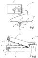
- FIG. 1 an apparatus 20 for coagulation and dissection is illustrated.
- the device 20 has a device 21 which provides a supply voltage UV or a supply current IV at a first device output 22.
- a second device output 23 is connected to ground M.
- An evaluation signal S is provided at a third device output 24.
- the evaluation signal S is a periodic signal, for example a voltage or a current, with first half-waves S1 of one polarity and second half-waves S2 of a different polarity.
- the first half-waves S1 are negative and the second half-waves S2 are positive, as is schematically shown in FIG Figure 4 is illustrated.
- the evaluation signal S is in Figure 4 illustrated as a square wave.
- the evaluation signal S could also have any other waveforms, for example a sinusoidal or a triangular waveform with positive and negative half waves.
- the evaluation signal S is preferably periodic. In modification of the illustrated embodiment, the evaluation signal S can also be aperiodic. It is also possible that the time period for a first half wave and the time period for a second half wave are of different lengths. In Figure 4 both the first half-waves S1 and the second half-waves S2 have the same length in time, so that each half-wave S1, S2 corresponds to half a period.
- An instrument 26 for coagulation and dissection is connected to the device 21 via a multi-core cable 25.
- the instrument 26 has a housing 27 with a handle 28 and a tool 29.
- the tool 29 is connected to the housing 27 via a connecting part 30.
- the connecting part 30 can be rod-shaped.
- An operating element 31 for the tool 29 is provided on the handle 28.
- the control element 31 is used for the mechanical and electrical actuation of the tool 29.
- a manually operable first switch 32 and a manually operable second switch 33 are present on the operating part 28.
- the two switches 32, 33 are designed as buttons and are in an electrically blocking state in their non-actuated idle state.
- FIG 2 is the tool 29 of the instrument 26 Figure 1 illustrated in a perspective partial representation.
- the tool 29 has two branches 34, 35 which are movable relative to one another and which are connected to one another in an articulated manner 36.
- the branches can be pivoted relative to one another via the control element 31.
- At least one first coagulation electrode 36 is arranged on one branch, while at least one second coagulation electrode 37 is arranged on the other branches is available.
- a first coagulation electrode 36 and an associated second coagulation electrode 37 each form a pair of coagulation electrodes.
- a plurality of pairs of coagulation electrodes can be present on the branches 34, 35.
- one of the branches also has a cutting electrode 38.
- the cutting electrode 38 is arranged as an insert in a groove-shaped depression on the branch 35 and is flanked by two first coagulation electrodes 36.
- the cutting electrode 38 is arranged on the tool 39 in an electrically insulated manner from the first coagulation electrodes 36.
- the plurality of first coagulation electrodes 36 can be electrically connected to one another.
- the branch 34 has an abutment 39 for the cutting electrode 38. If the tool 29 is closed via the control element 31, a first coagulation electrode 36 and a second coagulation electrode 37 lie opposite each other. The cutting electrode 38 lies adjacent or against the abutment 39. The electrical functions of the electrodes 36, 37, 38 can be operated via the switches 32, 33.
- FIG Figure 3 An embodiment of an operating circuit 45 of the instrument 26 is shown in FIG Figure 3 illustrated.
- the operating circuit 45 has a supply connection 46, by means of which the operating circuit 45 can be connected to the first device output 22, and a ground connection 47, by means of which the operating circuit 45 can be connected to the third device output 24.
- An evaluation connection 48 of the operating circuit 45 is connected to the third device output 24 connectable.
- the evaluation signal S of the device 21 is therefore present at the evaluation connection 48.
- the operating circuit 45 is connected to ground M via the ground connection 47.
- the supply connection 46 is applied to an HF current source or HF voltage source of the device 21 in order to provide a supply current IV or a supply voltage UV for the operating circuit 45.
- the supply connection 46 is connected to a coagulation output 50 via a first capacitor 49.
- the first coagulation output 50 is connected to the at least one first coagulation electrode 46.
- a second coagulation output 51 is connected to the at least one second coagulation electrode 47.
- the second coagulation output 51 is designed as a mass output.
- the second coagulation output 51 is connected to the ground connection 47 and thus to the ground M.
- the operating circuit 45 also has a switchover unit 53 which can be switched over by means of a drive signal A of a drive element 52.
- the switchover unit 53 is connected to the electrical connection between the supply connection 46 and a cutting output 54.
- the switching unit 53 is set up to provide a voltage and / or a current at the cutting output 54 in a first switching state, which is set up for dissection using the cutting electrode 38 and to provide essentially no electrical energy at the cutting output 54 in a second switching state. In the second switching state, the connection between the supply connection 46 and the cutting output 54 is interrupted, for example.
- the switchover unit 53 is designed without mechanical switches and has at least one semiconductor switch 55 and, in the exemplary embodiment, two semiconductor switches 55 connected in series.
- each semiconductor switch 55 is formed by a field effect transistor, which is illustrated here as a normally blocking n-channel MOSFET.
- Each semiconductor switch 55 has a control connection 56, which in the exemplary embodiment is formed by the gate of the MOSFETS.
- the two control connections 56 are preferably connected to one another.
- the two source connections of the MOSFETs can be connected to one another ( Fig. 13 ).
- the drain connections of the two MOSFETS each form a switching connection 57 of the switchover unit 53.
- the switching path of the switchover unit 53 is formed between the two switch connections 57.
- the one switching connection 57 of the switchover unit 53 is connected to the supply connection 46.
- the respective other switching connection 57 is connected to the switching output 54.
- the switchover unit 53 has, for example, a charge and discharge circuit 58 for the at least one semiconductor switch 55.
- the charging and discharging circuit 58 is set up to be able to hold electrical charges at the control connections 56 sufficiently long to be able to maintain the first switching state of the switchover unit 53 from a first half-wave S1 at least to the next first half-wave S1, as long as the first switch 32 is actuated is.
- the charging and discharging circuit 58 is set up to discharge the charges present at control connections 56, so that the Semiconductor switches 55 can also return to their non-conductive state when the first switch 32 is no longer actuated.
- the operating circuit 45 has a transformer circuit with a transformer 60.
- the transformer 60 has a primary winding 61 and a secondary winding 62.
- the transformer 60 is designed as an autotransformer.
- the primary winding 61 and the secondary winding 62 are connected in series and a center tap 63 is connected to an associated switching connection 57 of the switching device 53.
- a series circuit comprising the primary winding 61 and a second capacitor 64 is connected to ground M.
- a series circuit comprising the secondary winding 62 and a third capacitor 65 is connected to the cutting output 54.
- a first resistor 66 is connected in parallel with the third capacitor 65.
- the parallel connection of the third capacitor 65 and the first resistor 66 forms a spark detection circuit. If sparks occur, the supply current IV or the supply voltage UV has a DC component, which can be evaluated and recognized in the device 21. If such a spark detection after spark detection is not desired, the spark detection circuit can also be omitted.
- the operating circuit 45 also has an evaluation circuit 70, to which the control element 52 belongs.
- the evaluation circuit 70 is coupled to the switching unit 53 via a coupling device 71 in order to transmit the control signal A from the evaluation circuit 70 to the switching unit 53.
- the coupling device 71 has at least one transmitter component 72 in the evaluation circuit 70 and at least one receiver component 73, which is connected to the at least one control connection 56 of the switchover unit 53.
- the at least one transmitter component 72 is a light-emitting diode and the at least one receiver component 73 is a photodiode or, alternatively, a phototransistor.
- the coupling device 71 can thus be formed by an optocoupler 74.
- the transmitter component 72 is formed by the control element 52.
- the evaluation circuit 70 has the in Figure 3 Embodiment shown a first evaluation branch 75 with the first switch 32, a second evaluation branch 76 with the second switch 33 and a third evaluation branch 77.
- the three evaluation branches 75, 76, 77 are connected in parallel to one another between the ground connection 47 and the evaluation connection 48.
- the third evaluation branch 77 is formed by a series connection of a first diode 78 and a second resistor 79.
- the cathode of the first diode 78 is connected to the evaluation connection 58 and the anode to the second resistor 79.
- the second resistor 79 is connected to ground M at its other connection.
- the second evaluation branch 76 has a third resistor 80 which is connected in series with the second switch 33.
- the first evaluation path 75 has a one-way current path 81 and a parallel one in series with the first switch 72 parallel current path 82 connected to the one-way current path.
- the control element 52 is connected in series with the first switch 32.
- the one-way current path 81 has at least one component with a diode function, so that a current can only flow in one direction through the one-way current path 81 and, for example, from the evaluation connection 48 to the ground connection 47, provided the first switch 32 is closed.
- an additional component with a diode function is connected in series with the control element 52, for example a second diode 83.
- the anode of the second diode 83 is connected to the evaluation connection 48 and the cathode of the second diode 83 is connected to the control element 52 and, for example, with the anode of the light-emitting diode forming the control element 52.
- connection point between the second diode 83 and the control element 52 is connected to the second switch 33 via a connection current path 84 in the illustrated exemplary embodiment, so that the connection current path 84 and the second switch 33 are connected in parallel with the control element 52 and the first switch 32.
- a fourth resistor 85 is connected in parallel to the second diode 83 and the control element 72.
- a current flowing through the first evaluation branch 75 becomes the first current I1
- a current flowing through the second evaluation branch 76 becomes the second current I2 and a current flowing through the third evaluation branch 77 are referred to as the third current I3.
- the resistance values of the resistors 79, 85 and 80 in the evaluation branches 75, 76, 77 are selected so that the device 21 recognizes from the magnitude of the currents I1, I2, I3 whether and if so which switch 32, 33 is in its conductive state .
- the resistance values of the third resistor 80 and the fourth resistor 85 are of different sizes. This makes it possible to detect in device 21 which switch 32, 33 is conducting during a first half-wave S1 or which switch 32, 33 is blocking.
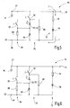
- both switches 32, 33 of the evaluation circuit 70 are not conductive, as is shown in FIGS Figures 5 and 6 is illustrated.
- a third current I3 flows only through the third evaluation path 77 and therefore through the second resistor 79 and the first diode 78 ( Figure 5 ).
- the device 21 can recognize that the other two evaluation paths 75, 76 are interrupted and should therefore neither be coagulated nor cut.
- no current flows through the evaluation circuit 70 ( Figure 6 ).
- FIGS Figures 7 and 8 An operator of the instrument actuates the first switch 32 so that it is switched to its conductive state, which is shown in FIGS Figures 7 and 8 is illustrated.
- a first current I1 flows through the first evaluation branch 75 and a third current I3 flows through the third evaluation branch 77 ( Figure 7 ).
- the first current I1 flows through the first switch 33 and the parallel current path 82, thus through the fourth resistor 85.
- the device 21 can therefore recognize that the first switch 32 has been actuated and is in its conductive state, while the second switch 33 is not conductive.
- the supply voltage UV or the supply current IV is provided at the first device output 22 and therefore at the supply connection 46.
- the first current I1 through the first evaluation branch 75 has a partial current I11 through the one-way current path 81 and a partial current I12 through the parallel current path 82.
- the partial current I11 through the one-way current path 81 is significantly larger than the partial current I12 through the parallel current path 82 because of the lower resistance value compared to the fourth resistor 85.
- the partial current I11 flows through the control element 52, which simultaneously represents the transmitter component 72.
- the control signal A is transmitted to the at least one receiver component 73 and switches the switchover unit 53 into the first switching state in which the at least one semiconductor switch 55 conducts and establishes an electrical connection between the switching connections 57.
- the drive signal A is formed, for example, by the light transmitted by the light-emitting diode (transmitter component 72) of the optocoupler 74, which ensures that the two photodiodes of the optocoupler 74, for example, generate a voltage which is used as a source for generating a drain-source voltage or Base-emitter voltage through the charging and discharge circuit 58 serves and thereby switches the at least one semiconductor switch 55 into the conductive state.
- the supply connection 46 is therefore connected to the cutting output 54 via the transformer 60 and at the cutting output 54 an increased voltage for dissection is provided by the transformer 60.
- the at least one receiver component 73 is connected to the control connection 56 of each semiconductor switch 55 via the charging and discharging circuit 58, on the one hand to be able to hold the charges in the control connections 56 sufficiently long (at least during the period of a first half-wave S1) and on the other hand those present there To be able to discharge charges again when the switching unit 53 is to be switched to the second switching state.
- the charge is maintained in the gate connections of the MOSFETs via the charging and discharging circuit 58, so that the switchover unit 53 remains in its second switching state (conductive state) even when a first half-wave S1 is present.
- the charge in the gates of the MOSFETs is maintained by the charging and discharging circuit 58 at least for the duration of a first half-wave S1 when the photodiodes of the optocoupler 74 are again triggered by the light-emitting diode of the optocoupler 74 during a second half-wave S2 when the first switch 32 is conductive will.
- the switchover unit 53 remains in its second switching state, in which no voltage or no current is provided at the cutting output 54. This is achieved in that a second current I2 flows through the second switch 33 during the second half-waves S2, a partial current I21 of the second current I2 through the third resistor 80 and another partial current I22 of the second current I2 through the second diode 83 and the connecting current path 84 flows.
- the control element 52 or the transmitter component 72 is without current, so that the semiconductor switches 55 remain in their non-conductive state ( Figure 10 ).
- a second half-wave S2 flows a second current I2 through the first switch 33 of the second evaluation branch 76, which is composed of a partial current I21 through the third resistor 80 and a partial current I22 through the second diode 83 and the connecting current path 84.
- a first current I1 flows through the parallel current path 82 and the first switch 32.
- the control element 52 or the transmission element 72 is currentless and thus the switchover unit 53 remains in its first switching state and no voltage or current is provided at the cutting output 54 for cutting .
- the control element 52 or the transmission element 72 is bridged or short-circuited by the second switch 33 with a low resistance.
- the structure of the evaluation circuit 70 prevents a cutting voltage from being applied to the cutting electrode 38 when the second switch 33 is actuated. Accidental cutting is therefore not possible if the second switch 33 is actuated to request coagulation.
- the at least one receiver component 73 has a first connection 73a of higher electrical potential (here: anode side of the at least one photodiode) and a second connection 73b of lower electrical potential (here: cathode side of the at least one photodiode).
- a higher potential is present at the first connection 73a when activated by the transmitter component 72 than at the second connection 73b.
- a fifth resistor 90 is connected in parallel with the at least one receiver component 73.
- the other side of the fourth capacitor 92 is connected to the second terminal 73b.
- the fifth resistor 90 is connected in parallel to the series circuit comprising the third diode 91 and the fourth capacitor 92.
- a series circuit comprising a fourth diode 93 and a fifth capacitor 94 is connected in parallel to the third diode 91, the anode of the fourth diode 93 being connected to the cathode of the third diode 91.
- the cathode of the fourth diode 93 is connected to an anode of a fifth diode 95.
- the cathode of the fifth diode 95 is connected to a sixth capacitor 96.
- the other terminal of the sixth capacitor 96 is connected to the second terminal 73b.
- the sixth capacitor 96 is connected between the control connections 56 (drain connections) and the connection point between the two series-connected semiconductor switches 55 (source connections).
- a sixth resistor 97 is connected in parallel with the sixth capacitor 96.
- the multiple cascades each consisting of a diode 91, 93, 95 and a capacitor 92, 94, 96 connected in series, serve to multiply the voltage applied to the at least one receiver component 73 when it is actuated by the transmitter component 72.
- the control of the semiconductor switches 55 and, according to the example, the charge in the gates of the field effect transistors can be maintained by the existing capacitors, even if no voltage is briefly applied to the at least one receiver component 73 during a first half-wave S1.
- the capacitors thus serve as buffer capacitors.
- the resistors 90, 97 of the charging and discharging circuit 58 are present.
- the charges in the drive connections 56 can balance out via the resistors 90, 97 and the semiconductor switches 55 can return to their blocking state.
- the period of time from the switching of the first switch 32 into the non-conductive state until the semiconductor switches 55 are blocked depends on the dimensioning of the components present in the charging and discharging circuit 58.
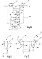
- FIG 14 is a modified embodiment of the third evaluation branch 77 illustrates.
- a transistor in particular a bipolar transistor, can be used, the collector connection of which is connected to the second resistor 79 and whose emitter connection is connected to the evaluation connection 48.
- the base connection of the transistor is connected to ground via a seventh resistor 101.
- the semiconductor switches 55 have bipolar transistors 103 and are each controlled by a semiconductor control switch 102.
- the semiconductor control switches 102 are formed by field effect transistors, for example by normally blocking n-channel MOSFETs.
- the control connections 56 of the semiconductor control switches 102 are connected to the charging and discharging circuit 58.
- the two collectors of the bipolar transistors 103 are connected to the charging and discharging circuit 58.
- Each emitter of a bipolar transistor 103 forms a switching connection 57.
- the collectors of the bipolar transistors 103 are also connected to the source connections of the field-effect transistors forming the semiconductor control switches 102.
- each bipolar transistor 103 is connected to the drain terminal of an associated field effect transistor. As soon as the gate-source voltage is sufficiently high, the semiconductor control switches 102 become conductive, so that a base current flows out of the PNP bipolar transistors 103 and these change into their conductive state.
- the invention relates to an instrument for optional coagulation and dissection of biological tissue.
- the instrument has a tool 29 with coagulation electrodes 36 and at least one cutting electrode 38.
- the electrodes 36, 38 are controlled via an operating circuit 45.
- the operating circuit 45 has an evaluation circuit 70, which is supplied with an evaluation signal S with first half-waves S1 and second half-waves S2 from an external device 21.
- the first half-waves S1 and the second half-waves S2 have opposite polarities.
- the evaluation circuit 70 checks whether a first switch 32 or a second switch 33 or both switches 32, 33 are actuated on the instrument 26.
- a control signal A is generated and transmitted to a switchover unit 53, in particular using a coupling device 71 with electrical isolation.
- the switching unit 53 is switched to a first switching state or a second switching state. In the second switching state, no voltage suitable for dissection or no current suitable for dissection is applied to the cutting electrode 38.
- a voltage suitable for the dissection or a current suitable for the dissection is applied to the cutting electrode 38.
- the first switching state is preferably initiated via the control signal A when the evaluation circuit 70 detects that only the first switch 32 is actuated.
Landscapes
- Health & Medical Sciences (AREA)
- Surgery (AREA)
- Life Sciences & Earth Sciences (AREA)
- Engineering & Computer Science (AREA)
- Molecular Biology (AREA)
- Biomedical Technology (AREA)
- Heart & Thoracic Surgery (AREA)
- Medical Informatics (AREA)
- Nuclear Medicine, Radiotherapy & Molecular Imaging (AREA)
- Animal Behavior & Ethology (AREA)
- General Health & Medical Sciences (AREA)
- Public Health (AREA)
- Veterinary Medicine (AREA)
- Physics & Mathematics (AREA)
- Plasma & Fusion (AREA)
- Otolaryngology (AREA)
- Surgical Instruments (AREA)
Abstract
Description
- Die Erfindung betrifft ein Instrument zur Koagulation und Dissektion von biologischem Gewebe.
- Ein solches Instrument ist beispielsweise aus
EP 3 132 765 A1 bekannt. Das Instrument hat ein Werkzeug mit einer Schneidelektrode und mehreren Koagulationselektroden. Mittels einer Betriebsschaltung können die Elektroden mit elektrischer Energie versorgt werden. Hierzu weist die Betriebsschaltung einen Transformator auf, der sekundärseitig über einen Leistungsschalter mit der Schneidelektrode verbunden ist. Das Instrument hat einen Schneidaktivierungsschalter und einen Koagulationsaktivierungsschalter. Der Koagulationsaktivierungsschalter ist mechanisch mit dem Leistungsschalter gekoppelt. Beim Betätigen des Koagulationsaktivierungsschalters wird die elektrische Verbindung zwischen der Schneidelektrode und dem Transformator getrennt oder umgeschaltet, so dass keine Schneidspannung an der Schneidelektrode anliegt. - Instrumente zur Koagulation bzw. Dissektion von biologischem Gewebe werden sowohl als Mehrweginstrument als auch als Einweginstrument angeboten. Insbesondere bei Einweginstrumenten spielen die Herstellungskosten eine große Rolle. Es kann daher als Aufgabe der vorliegenden Erfindung angesehen werden, ein Instrument zu schaffen, das einfach und sicher zu bedienen ist und sich kostengünstig herstellen lässt.
- Diese Aufgabe wird durch ein Instrument mit den Merkmalen des Patentanspruches 1 und ein Verfahren mit den Merkmalen des Patentanspruches 14 gelöst.
- Das Instrument ist zur Koagulation und Dissektion von biologischem Gewebe eingerichtet. Es hat ein Werkzeug mit wenigstens einer Schneidelektrode und wenigstens einem Koagulationselektrodenpaar. Jedes Koagulationselektrodenpaar hat eine erste Koagulationselektrode und eine zweite Koagulationselektrode. Das Instrument weist eine Betriebsschaltung auf. Die Betriebsschaltung hat einen mit der Schneidelektrode verbundenen Schneidausgang, einen mit der wenigstens einen ersten Koagulationselektrode verbundenen ersten Koagulationsausgang und einen mit der wenigstens einen zweiten Koagulationselektrode verbundenen zweiten Koagulationsausgang. Die Betriebsschaltung weist außerdem einen Versorgungsanschluss auf, mittels dem eine Versorgungsspannung oder ein Versorgungsstrom bereitgestellt wird. Ferner ist ein Auswerteanschluss vorhanden, mittels dem ein periodisches Auswertesignal mit ersten Halbwellen einer Polarität und zweiten Halbwellen der jeweils anderen Polarität bereitgestellt wird. Beispielsweise sind die ersten Halbwellen negative Halbwellen und die zweiten Halbwellen positive Halbwellen des Auswertesignals. Das Auswertesignal kann ein Strom oder eine Spannung sein.
- Die Betriebsschaltung hat außerdem eine mit dem Auswerteanschluss verbundene Auswerteschaltung aufweisend einen manuell betätigbaren ersten Schalter und ein Ansteuerelement zur Erzeugung eines Ansteuersignals. Das Ansteuerelement kann ein einzelnes Bauelement sein oder eine Gruppe aus mehreren Einzelelementen. Die Auswerteschaltung ist dazu eingerichtet, während wenigstens einer der ersten Halbwellen auszuwerten, ob der erste Schalter betätigt wurde. Abhängig von diesem Auswerteergebnis wird dann beginnend mit einer der nachfolgenden zweiten Halbwellen das dem Auswerteergebnis entsprechende Ansteuersignal erzeugt. Mittels des Ansteuersignals wird eine ansteuerbare Umschalteinheit zwischen einem ersten Schaltzustand und einem zweiten Schaltzustand umgeschaltet. Die Umschalteinheit kann mittelbar oder unmittelbar mit dem Versorgungseingang bzw. dem Schneidausgang verbunden sein. Sie kann bei einem bevorzugten Ausführungsbeispiel in Reihe zwischen dem Versorgungsanschluss und dem Schneidausgang angeordnet sein. In diesem Fall kann die Umschalteinheit beispielsweise zwischen einem leitenden und einem sperrenden Schaltzustand umgeschaltet werden. Es ist auch möglich, die Umschalteinheit zwischen zwei leitenden Schaltzuständen umzuschalten, wobei der Schneidausgang in diesem Fall mit unterschiedlichen Spannungen oder Strömen versorgt wird. Im ersten Schaltzustand der Umschalteinheit liegt am Schneidausgang und mithin an der Schneidelektrode eine elektrische Spannung an oder es wird ein elektrischer Strom bereitgestellt, der zur Dissektion von biologischem Gewebe geeignet ist. Demgegenüber ist an der Schneidelektrode im zweiten Schaltzustand keine elektrische Spannung oder kein elektrischer Strom verfügbar, der ausreichend ist für die Dissektion von biologischem Gewebe. Im zweiten Schaltzustand kann entweder im Wesentlichen keine Spannung oder kein Strom an der Schneidelektrode verfügbar sein oder alternativ eine Spannung oder ein Strom bereitgestellt werden, der für die Dissektion nicht ausreichend ist, aber z.B. für die Koagulation geeignet ist.
- Das Auswertesignal wird zur Abfrage, ob der erste Schalter betätigt wurde, durch ein Gerät bereitgestellt, an das das Instrument anschließbar ist. Der Betätigungszustand des ersten Schalters wird während wenigstens einer ersten Halbwelle ausgewertet und bei einer Änderung des Betätigungszustands wird während wenigstens einer der darauf folgenden zweiten Halbwellen das Ansteuersignal an dem geänderten Betätigungszustand des ersten Schalters angepasst. Außerdem kann das Gerät dem Instrument am Versorgungseingang bei festgestellter Betätigung des ersten Schalters eine Versorgungsspannung oder einen Versorgungsstrom bereitstellen. Insbesondere wird die Umschalteinheit bei unbetätigtem ersten Schalter durch das Ansteuersignal in den zweiten Schaltzustand umgeschaltet, in dem keine elektrische Energie für die Dissektion an der Schneidelektrode bereitsteht. Wird das Betätigen des ersten Schalters erkannt, wird ein Ansteuersignal erzeugt, das die Umschalteinheit in den ersten Schaltzustand umschaltet, in dem dann an der Schneidelektrode eine elektrische Energie für die Dissektion bereitgestellt wird.
- Eine mechanische Kopplung zwischen der Umschalteinrichtung und der Auswerteschaltung kann entfallen. Das Instrument lässt sich sehr einfach mit Standard-Bauelementen aufbauen. Insbesondere kann die Umschalteinheit über einen oder mehrere Halbleiterschalter aufgebaut werden. Mechanische Schalter können in der Umschalteinheit entfallen. Dadurch ist eine einfache Vermeidung von Funken- oder Lichtbogenbildung beim Ändern des Schaltzustands erreicht. Die Lösung kann kostengünstig auch bei Einweginstrumenten realisiert werden.
- Es ist vorteilhaft, wenn die Betriebsschaltung eine Kopplungseinrichtung aufweist, die ein Senderbauteil und ein galvanisch vom Senderbauteil getrenntes Empfängerbauteil aufweist. Über das Senderbauteil kann das Ansteuersignal von der Auswerteschaltung zum Empfängerbauteil übertragen werden, das mit der Umschalteinheit verbunden ist oder zur Umschalteinheit gehört.
- Bei einem Ausführungsbeispiel ist das Senderbauteil durch das Ansteuerelement gebildet. Dabei kann das Empfängerbauteil mit einem Steuereingang eines ansteuerbaren Halbleiterschalters der Umschalteinrichtung verbunden sein.
- Als Senderbauteil kann beispielsweise wenigstens eine Leuchtdiode und als Empfängerbauteil wenigstens eine Fotodiode oder wenigstens eine Fototransistor verwendet werden. Beispielsweise kann das Senderbauteil und das Empfängerbauteil als gemeinsame Baugruppe in einem gemeinsamen Gehäuse angeordnet werden. Diese Baugruppe kann beispielsweise ein Optokoppler sein.
- Es ist vorteilhaft, wenn das Empfängerbauteil über eine Lade- und Entladeschaltung mit dem wenigstens einen Steuereingang der Umschalteinheit verbunden ist. Mittels der Lade- und Entladeschaltung ist es möglich den ersten Schaltzustand der Umschalteinheit bei einer Dissektionsanforderung (z.B. Betätigen des ersten Schalters) auch während der Zeitdauer aufrechtzuerhalten, während der eine erste Halbwelle anliegt. Vorzugsweise ist die Lade- und Entladeschaltung auch dazu eingerichtet, die elektrischen Ladungen im wenigstens einen Steuereingang der Umschalteinheit abzubauen, wenn keine zur Dissektion geeignete Spannung an die Schneidelektrode angelegt werden soll, um ein Umschalten der Umschalteinheit in den zweiten Schaltzustand zu ermöglichen.
- Die Umschalteinheit kann bei einem Ausführungsbeispiel ohne mechanische Schalter ausgebildet sein und ausschließlich Halbleiterschalter aufweisen, wie etwa Bipolartransistoren und/oder Feldeffekttransistoren und/oder IGBTs.
- Es ist vorteilhaft, wenn der erste Schalter und das Ansteuerelement in einem ersten Auswertezweig in Reihe geschaltet sind. Der erste Auswertezweig kann mit dem Auswerteanschluss verbunden sein. Dadurch kann ein Stromfluss durch das Ansteuerelement bei geöffnetem ersten Schalter unterbunden werden.
- Beispielsweise kann im ersten Auswertezweig ein Einbahnstrompfad vorhanden sein, in dem das Ansteuerelement angeordnet ist. In dem Einbahnstrompfad wird der Stromfluss nur in eine Richtung zugelassen, insbesondere in die Stromflussrichtung bei anliegender zweiter Halbwelle des Auswertesignals. In dem Einbahnstrompfad ist dazu wenigstens ein Bauteil mit Diodenfunktion vorhanden. Das Bauteil mit Diodenfunktion kann beispielsweise das Ansteuerelement selbst sein. Alternativ oder zusätzlich kann ein weiteres Bauteil mit Diodenfunktion, im einfachsten Fall eine Diode, im Einbahnstrompfad vorhanden sein. Alternativ zur Diode können auch gesteuerte Halbleitschalter verwendet werden, die nur bei einer zweiten Halbwelle des Auswertesignals ihren leitenden Zustand einnehmen.
- Bei einem Ausführungsbeispiel ist das Ansteuerelement als Leuchtdiode ausgeführt. Zusätzlich zu der Leuchtdiode kann im Einbahnstrompfad eine separate Diode in Reihe zum Ansteuerelement geschaltet sein, vorzugsweise in Stromflussrichtung stromaufwärts.
- Es ist außerdem vorteilhaft, wenn im ersten Auswertezweig parallel zum Einbahnstrompfad ein weiterer Parallelstrompfad vorhanden ist, indem beispielsweise ein Widerstand angeordnet sein kann. Wenn in der vorliegenden Anmeldung von einem Widerstand die Rede ist, ist ein Ohmscher Widerstand gemeint, solange nichts anderes angegeben ist. Der erste Schalter ist vorzugsweise in Reihe zum Einbahnstrompfad und zum Parallelstrompfad geschaltet.
- Bei einer Ausführungsform der Erfindung ist in der Auswerteschaltung ein manuell betätigbarer zweiter Schalter vorhanden. Die beiden Schalter können so ausgeführt sein, dass sie unabhängig voneinander - also jeweils einzeln oder auch beide gleichzeitig - betätigbar sind. Alternativ dazu können die beiden Schalter auch mechanisch gekoppelt sein, so dass immer nur einer der beiden Schalter betätigt werden kann, wie es etwa bei einer Schaltwippe der Fall ist. Bei einem bevorzugten Ausführungsbeispiel sind der erste Schalter und der zweite Schalter jeweils als Taster ausgebildet, die in ihrem Ruhezustand in einem sperrenden Zustand sind und manuell in den leitenden Zustand umgeschaltet werden können.
- Es ist außerdem vorteilhaft, wenn der zweite Schalter in einem zweiten Auswertezweig der Auswerteschaltung angeordnet ist. Der zweite Auswertezweig ist mit dem Auswerteanschluss verbunden. Vorzugsweise ist in Reihe zum zweiten Schalter ein Widerstand geschaltet.
- Bei einem Ausführungsbeispiel sind der zweite Schalter und das Ansteuerelement über einen Verbindungsstrompfad gekoppelt. Beispielsweise kann der Verbindungsstrompfad eine permanente, nicht sperrbare elektrische Verbindung zwischen dem zweiten Schalter und dem Ansteuerelement herstellen. Der Verbindungsstrompfad kann bauteilfrei ausgebildet sein. Insbesondere sind der zweite Schalter und der Verbindungsstrompfad parallel zum Ansteuerelement und dem ersten Schalter geschaltet. Bei geschlossenem bzw. leitendem zweiten Schalter wird eine niederohmige Überbrückung des Ansteuerelements bewirkt. Bei leitendem zweiten Schalter kann somit kein Stromfluss durch das Ansteuerelement erfolgen. Unter einer niederohmigen Überbrückung des Ansteuerelements ist eine Überbrückung zu verstehen, die einen derart geringen Widerstandswert hat, dass der Spannungsabfall an der Überbrückung im Wesentlichen gleich null ist und insbesondere kleiner ist als eine Aktivierungsspannung des Ansteuerelements, beispielsweise die Flussspannung einer Leuchtdiode.
- Es ist außerdem vorteilhaft, wenn der erste Koagulationsausgang der Betriebsschaltung schalterlos mit dem Versorgungseingang verbunden ist. In dieser Verbindung kann beispielsweise ein Kondensator angeordnet sein.
- Vorzugsweise hat die Betriebsschaltung eine Transformatorschaltung mit einem Transformator. Die Transformatorschaltung ist primärseitig mit dem Versorgungseingang und sekundärseitig mit dem Schneidausgang verbunden, wobei diese Verbindungen mittelbar oder unmittelbar sein können. Der Transformator der Transformatorschaltung kann ohne galvanische Trennung als Spartransformator ausgeführt sein. Der Transformator kann alternativ auch eine von der Sekundärseite galvanisch getrennte Primärseite aufweisen. Die Transformatorschaltung ist insbesondere dazu eingerichtet, die am Versorgungsanschluss anliegende Versorgungsspannung zu erhöhen, beispielsweise von etwa 100 Volt auf etwa 450 Volt Wechselspannung.
- Ein Verfahren zum Betreiben eines Instruments zur Koagulation und Dissektion von biologischem Gewebe, insbesondere unter Verwendung des vorstehend beschriebenen Instruments, weist folgende Schritte auf:
- Zunächst wird ein Auswertesignal mit ersten Halbwellen einer Polarität und zweiten Halbwellen der jeweils anderen Polarität an den Auswerteanschluss angelegt. Anschließend wird ausgewertet, dass der erste Schalter in seinem leitenden Zustand oder seinem sperrenden Zustand ist. Diese Auswertung findet während wenigstens einer der ersten Halbwellen statt. Während wenigstens einer der nachfolgenden zweiten Halbwellen wird abhängig vom Auswerteergebnis ein Ansteuersignal für die Umschalteinheit erzeugt. Insbesondere wird dann, wenn festgestellt wurde, dass der erste Schalter manuell betätigt wurde, eine Versorgungsspannung an den Versorgungseingang angelegt. Das Instrument erzeugt ein Ansteuersignal, das die Umschalteinheit bei betätigtem ersten Schalter in den ersten Schaltzustand umschaltet, in dem der Schneidausgang - vorzugsweise über eine Transformatorschaltung - mit dem Versorgungsanschluss verbunden ist, so dass eine elektrische Spannung oder ein elektrischer Strom an dem Schneidausgang bereitgestellt wird, der für die Dissektion geeignet ist.
- Insbesondere wird eine für die Dissektion geeignete Spannung oder ein für die Dissektion geeigneter Strom nicht an die Schneidelektrode angelegt, wenn erkannt wurde, dass der zweite Schalter des Instruments betätigt wurde, unabhängig vom Betätigungszustand des ersten Schalters. In diesem Fall wird ein Ansteuersignal erzeugt, dass die Umschalteinheit in den zweiten Schaltzustand umschaltet.
- Vorteilhafte Ausgestaltungen der Erfindung ergeben sich aus den abhängigen Patentansprüchen, der Beschreibung und der Zeichnungen. Nachfolgend werden bevorzugte Ausführungsbeispiele der Erfindung anhand der beigefügten Zeichnungen im Einzelnen erläutert. Es zeigen:
-
Figur 1 eine schematische Darstellung einer Vorrichtung 20 zur Koagulation und Dissektion mit einem Gerät und einem elektrisch mit dem Gerät verbundenen Instrument, -
Figur 2 eine perspektivische Teildarstellung eines Werkzeugs des Instruments ausFigur 1 , -
Figur 3 einen Schaltplan eines Ausführungsbeispiels einer Betriebsschaltung des Instruments, -
Figur 4 eine schematische Darstellung eines zeitlichen Verlaufs eines beispielhaften Auswertesignals, -
Figuren 5-12 einen Schaltplan eines Ausführungsbeispiels einer Auswerteschaltung der Betriebsschaltung ausFigur 3 in jeweils unterschiedlichen Zuständen, -
Figur 13 einen Schaltplan einer optionalen Spannungserhöhungsschaltung für die Betriebsschaltung ausFigur 3 , -
Figur 14 ein abgewandeltes Ausführungsbeispiel zur Realisierung einer Diodenfunktion mittels eines Transistors und -
Figur 15 ein Schaltplan für ein abgewandeltes Ausführungsbeispiel für eine Umschalteinheit für die Betriebsschaltung ausFigur 3 . - In
Figur 1 ist eine Vorrichtung 20 zur Koagulation und Dissektion veranschaulicht. Die Vorrichtung 20 hat ein Gerät 21, das an einem ersten Geräteausgang 22 eine Versorgungsspannung UV oder einen Versorgungsstrom IV bereitstellt. Ein zweiter Geräteausgang 23 ist mit Masse M verbunden. An einem dritten Geräteausgang 24 wird ein Auswertesignal S bereitgestellt. Das Auswertesignal S ist beim Ausführungsbeispiel ein periodisches Signal, beispielsweise eine Spannung oder ein Strom, mit ersten Halbwellen S1 einer Polarität und zweiten Halbwellen S2 einer jeweils anderen Polarität. Beim Ausführungsbeispiel sind die ersten Halbwellen S1 negativ und die zweiten Halbwellen S2 positiv, wie es schematisch inFigur 4 veranschaulicht ist. Das Auswertesignal S ist inFigur 4 als Rechtecksignal veranschaulicht. Alternativ dazu könnte das Auswertesignal S auch irgendwelche anderen Wellenformen aufweisen, beispielsweise eine sinusförmige oder eine dreieckförmige Wellenform mit positiven und negativen Halbwellen. - Das Auswertesignal S ist vorzugsweise periodisch. In Abwandlung zum veranschaulichten Ausführungsbeispiel kann das Auswertesignal S aber auch aperiodisch sein. Es ist außerdem möglich, dass die Zeitdauer für eine erste Halbwelle und die Zeitdauer für eine zweite Halbwelle unterschiedlich lang sind. In
Figur 4 haben sowohl die ersten Halbwellen S1, als auch die zweiten Halbwellen S2 dieselbe zeitliche Länge, so dass jede Halbwelle S1, S2 einer halben Periodendauer entspricht. - An das Gerät 21 ist über ein mehradriges Kabel 25 ein Instrument 26 zur Koagulation und Dissektion angeschlossen. Das Instrument 26 hat ein Gehäuse 27 mit Handgriff 28 sowie ein Werkzeug 29. Das Werkzeug 29 ist beim Ausführungsbeispiel über ein Verbindungsteil 30 mit dem Gehäuse 27 verbunden. Das Verbindungsteil 30 kann stabförmig ausgeführt sein. An dem Handgriff 28 ist ein Bedienelement 31 für das Werkzeug 29 vorhanden. Das Bedienelement 31 dient zur mechanischen und elektrischen Betätigung des Werkzeugs 29. An dem Bedienteil 28 ist ein manuell betätigbarer erster Schalter 32 sowie ein manuell betätigbarer zweiter Schalter 33 vorhanden. Die beiden Schalter 32, 33 sind beim Ausführungsbeispiel als Taster ausgebildet und befinden sich in ihrem nicht betätigten Ruhezustand in einem elektrisch sperrenden Zustand.
- In
Figur 2 ist das Werkzeug 29 des Instruments 26 ausFigur 1 in einer perspektivischen Teildarstellung veranschaulicht. Das Werkzeug 29 hat zwei relativ zueinander bewegbare Branchen 34, 35, die in einem Gelenk 36 gelenkig miteinander verbunden sind. Über das Bedienelement 31 können die Branchen relativ zueinander geschwenkt werden. An der einen Branche ist wenigstens eine erste Koagulationselektrode 36 angeordnet, während an die jeweils anderen Branchen wenigstens eine zweite Koagulationselektrode 37 vorhanden ist. Jeweils eine erste Koagulationselektrode 36 und eine zugeordnete zweite Koagulationselektrode 37 bilden ein Koagulationselektrodenpaar. An den Branchen 34, 35 können mehrere Koagulationselektrodenpaare vorhanden sein. - Außerdem verfügt eine der Branchen zusätzlich über eine Schneidelektrode 38. Die Schneidelektrode 38 ist beim Ausführungsbeispiel als Einsatz in einer nutförmigen Vertiefung an der Branche 35 angeordnet und durch zwei erste Koagulationselektroden 36 flankiert. Die Schneidelektrode 38 ist von den ersten Koagulationselektroden 36 elektrisch isoliert am Werkzeug 39 angeordnet. Die mehreren ersten Koagulationselektroden 36 können elektrisch miteinander verbunden sein.
- Der Branche 34 ist ein Widerlager 39 für die Schneidelektrode 38 angeordnet. Wird das Werkzeug 29 über das Bedienelement 31 geschlossen, liegen sich jeweils eine erste Koagulationselektrode 36 und eine zweite Koagulationselektrode 37 gegenüber. Die Schneidelektrode 38 liegt benachbart oder am Widerlager 39 an. Über die Schalter 32, 33 können die elektrischen Funktionen der Elektroden 36, 37, 38 bedient werden.
- Ein Ausführungsbeispiel einer Betriebsschaltung 45 des Instruments 26 ist in
Figur 3 veranschaulicht. Die Betriebsschaltung 45 hat einen Versorgungsanschluss 46, mittels dem die Betriebsschaltung 45 an den ersten Geräteausgang 22 anschließbar ist sowie einen Masseanschluss 47, mittels dem die Betriebsschaltung 45 mit dem dritten Geräteausgang 24 verbindbar ist. Ein Auswerteanschluss 48 der Betriebsschaltung 45 ist mit dem dritten Geräteausgang 24 verbindbar. Am Auswerteanschluss 48 liegt daher das Auswertesignal S des Geräts 21 an. Über den Masseanschluss 47 wird die Betriebsschaltung 45 mit Masse M verbunden. Der Versorgungsanschluss 46 wird an eine HF-Stromquelle oder HF-Spannungsquelle des Geräts 21 angelegt, um einen Versorgungsstrom IV oder eine Versorgungsspannung UV für die Betriebsschaltung 45 bereitzustellen. - Der Versorgungsanschluss 46 ist über einen ersten Kondensator 49 mit einem Koagulationsausgang 50 verbunden. Der erste Koagulationsausgang 50 ist mit der wenigstens einen ersten Koagulationselektrode 46 verbunden. Ein zweiter Koagulationsausgang 51 ist mit der wenigstens einen zweiten Koagulationselektrode 47 verbunden. Der zweite Koagulationsausgang 51 ist beim Ausführungsbeispiel als Masseausgang ausgeführt. Der zweite Koagulationsausgang 51 ist dazu mit dem Masseanschluss 47 uns mithin mit der Masse M verbunden.
- Die Betriebsschaltung 45 weist außerdem eine mittels eines Ansteuersignals A eines Ansteuerelements 52 umschaltbare Umschalteinheit 53 auf. Die Umschalteinheit 53 ist in die elektrische Verbindung zwischen dem Versorgungsanschluss 46 und einem Schneidausgang 54 geschaltet. Die Umschalteinheit 53 ist dazu eingerichtet, am Schneidausgang 54 in einem ersten Schaltzustand eine Spannung und/oder einen Strom bereitzustellen, der für eine Dissektion unter Verwendung der Schneidelektrode 38 eingerichtet ist und in einem zweiten Schaltzustand an dem Schneidausgang 54 im Wesentlichen keine elektrische Energie bereitzustellen. Im zweiten Schaltzustand wird beispielsgemäß die Verbindung zwischen dem Versorgungsanschluss 46 und dem Schneidausgang 54 unterbrochen.
- Die Umschalteinheit 53 ist ohne mechanische Schalter ausgeführt und weist wenigstens einen Halbleitschalter 55 und beim Ausführungsbeispiel zwei in Reihe geschaltete Halbleiterschalter 55 auf. Beispielsgemäß ist jeder Halbleiterschalter 55 durch einen Feldeffekttransistor gebildet, der hier als normal sperrender n-Kanal MOSFET veranschaulicht ist. Jeder Halbleiterschalter 55 hat einen Steueranschluss 56, der beim Ausführungsbeispiel durch das Gate der MOSFETS gebildet ist.
- Die beiden Steueranschlüsse 56 sind vorzugsweise miteinander verbunden. Außerdem können die beiden Source-Anschlüsse der MOSFETS miteinander verbunden sein (
Fig. 13 ) . - Die Drain-Anschlüsse der beiden MOSFETS bilden jeweils einen Schaltanschluss 57 der Umschalteinheit 53. Zwischen den beiden Schaltanschlüssen 57 ist die Schaltstrecke der Umschalteinheit 53 gebildet. Der eine Schaltanschluss 57 der Umschalteinheit 53 ist mit dem Versorgungsanschluss 46 verbunden. Der jeweils andere Schaltanschluss 57 ist mit dem Schaltausgang 54 verbunden.
- Die Umschalteinheit 53 weist beispielsgemäß eine Lade- und Entladeschaltung 58 für den wenigstens einen Halbleitschalter 55 auf. Die Lade- und Entladeschaltung 58 ist dazu eingerichtet elektrische Ladungen an den Steueranschlüssen 56 ausreichend lange halten zu können, um den ersten Schaltzustand der Umschalteinheit 53 von einer ersten Halbwelle S1 mindestens bis zur nächsten ersten Halbwelle S1 aufrechterhalten zu können, solange der erste Schalter 32 betätigt ist. Andererseits ist die Lade- und Entladeschaltung 58 dazu eingerichtet, die an Steueranschlüssen 56 vorhandenen Ladungen abzuführen, so dass die Halbleiterschalter 55 auch wieder in ihren nicht leitenden Zustand übergehen können, wenn der erste Schalter 32 nicht mehr betätigt wird.
- Die Betriebsschaltung 45 hat beim Ausführungsbeispiel eine Transformatorschaltung mit einem Transformator 60. Der Transformator 60 weist eine Primärwicklung 61 und eine Sekundärwicklung 62 auf. Beim Ausführungsbeispiel ist der Transformator 60 als Spartransformator ausgebildet. Die Primärwicklung 61 und die Sekundärwicklung 62 sind dabei in Reihe geschaltet und ein Mittelabgriff 63 ist mit einem zugeordneten Schaltanschluss 57 der Umschalteinrichtung 53 verbunden. Ausgehend vom Mittelabgriff 63 ist eine Reihenschaltung aus der Primärwicklung 61 und einem zweiten Kondensator 64 mit Masse M verbunden. Ausgehend vom Mittelabgriff 63 ist eine Reihenschaltung aus der Sekundärwicklung 62 und einem dritten Kondensator 65 mit dem Schneidausgang 54 verbunden. Parallel zum dritten Kondensator 65 ist ein erster Widerstand 66 geschaltet. Die Parallelschaltung aus dem dritten Kondensator 65 und dem ersten Widerstand 66 bildet eine Funkenerkennungsschaltung. Treten Funken auf, hat der Versorgungsstrom IV bzw. die Versorgungsspannung UV einen Gleichanteil, was in dem Gerät 21 ausgewertet und erkannt werden kann. Ist eine solche Funkenerkennung nach Funkenerkennung nicht gewünscht, kann die Funkenerkennungsschaltung auch entfallen.
- Die Betriebsschaltung 45 verfügt außerdem über eine Auswerteschaltung 70, zu der das Ansteuerelement 52 gehört. Die Auswerteschaltung 70 ist über eine Kopplungseinrichtung 71 mit der Umschalteinheit 53 gekoppelt, um das Ansteuersignal A von der Auswerteschaltung 70 zu der Umschalteinheit 53 zu übertragen. Die Kopplungseinrichtung 71 hat hierfür wenigstens ein Senderbauteil 72 in der Auswerteschaltung 70 und wenigstens ein Empfängerbauteil 73, das mit dem wenigstens einen Steueranschluss 56 der Umschalteinheit 53 verbunden ist. Beim Ausführungsbeispiel ist das wenigstens eine Senderbauteil 72 eine Leuchtdiode und das wenigstens eine Empfängerbauteil 73 eine Fotodiode oder alternativ ein Fototransistor. Die Kopplungseinrichtung 71 kann somit durch einen Optokoppler 74 gebildet sein. Bei dem hier gezeigten Ausführungsbeispiel ist das Senderbauteil 72 durch das Ansteuerelement 52 gebildet.
- Die Auswerteschaltung 70 weist bei dem in
Figur 3 gezeigten Ausführungsbeispiel einen ersten Auswertezweig 75 mit dem ersten Schalter 32, einen zweiten Auswertezweig 76 mit dem zweiten Schalter 33 sowie einen dritten Auswertezweig 77 auf. Die drei Auswertezweige 75, 76, 77 sind parallel zueinander zwischen den Masseanschluss 47 und den Auswerteanschluss 48 geschaltet. - Der dritte Auswertezweig 77 ist beim Ausführungsbeispiel durch eine Reihenschaltung aus einer ersten Diode 78 und einem zweiten Widerstand 79 gebildet. Die Kathode der ersten Diode 78 ist mit dem Auswerteanschluss 58 und die Anode mit dem zweiten Widerstand 79 verbunden. Der zweite Widerstand 79 ist mit seinem anderen Anschluss mit Masse M verbunden.
- Der zweite Auswertezweig 76 weist zusätzlich zum zweiten Schalter 33 einen dritten Widerstand 80 auf, der in Reihe zum zweiten Schalter 33 geschaltet ist.
- Der erste Auswertepfad 75 hat in Reihe zum ersten Schalter 72 einen Einbahnstrompfad 81 sowie einen parallel zum Einbahnstrompfad geschalteten Parallelstrompfad 82. Im Einbahnstrompfad 81 ist das Ansteuerelement 52 in Reihe zum ersten Schalter 32 geschaltet. Der Einbahnstrompfad 81 weist mit wenigstens einem Bauteil mit Diodenfunktion auf, so dass ein Strom durch den Einbahnstrompfad 81 nur in eine Richtung fließen kann und beispielsgemäß vom Auswerteanschluss 48 zum Masseanschluss 47, sofern der erste Schalter 32 geschlossen ist. Bei dem hier dargestellten Ausführungsbeispiel ist in Reihe zu dem Ansteuerelement 52 ein zusätzliches Bauteil mit Diodenfunktion geschaltet, beispielsgemäß eine zweite Diode 83. Die Anode der zweiten Diode 83 ist mit dem Auswerteanschluss 48 verbunden und die Kathode der zweiten Diode 83 ist mit dem Ansteuerelement 52 verbunden und beispielsgemäß mit der Anode der das Ansteuerelement 52 bildenden Leuchtdiode.
- Außerdem ist der Verbindungspunkt zwischen der zweiten Diode 83 und dem Ansteuerelement 52 bei dem veranschaulichten Ausführungsbeispiel über einen Verbindungsstrompfad 84 mit dem zweiten Schalter 33 verbunden, so dass der Verbindungsstrompfad 84 und der zweite Schalter 33 parallel zum Ansteuerelement 52 und dem ersten Schalter 32 geschaltet sind.
- Im Parallelstrompfad 82 ist parallel zur zweiten Diode 83 und dem Ansteuerelement 72 ein vierter Widerstand 85 geschaltet.
- Die Funktionsweise der Betriebsschaltung 45 wird nachfolgend anhand der
Figuren 5 bis 12 erläutert. Zur Unterscheidung wird dabei ein durch den ersten Auswertezweig 75 fließender Strom als erster Strom I1, ein durch den zweiten Auswertezweig 76 fließender Strom als zweiter Strom I2 und ein durch den dritten Auswertezweig 77 fließender Strom als dritter Strom I3 bezeichnet. Die Widerstandswerte der Widerstände 79, 85 und 80 in den Auswertezweigen 75, 76, 77 werden so gewählt, dass das Gerät 21 am Betrag der Ströme I1, I2, I3 erkennt, ob und wenn ja welcher Schalter 32, 33 in seinem leitenden Zustand ist. Insbesondere sind die Widerstandswerte des dritten Widerstands 80 und des vierten Widerstands 85 unterschiedlich groß. Dadurch ist im Gerät 21 eine Erkennung möglich, welcher der Schalter 32, 33 während einer ersten Halbwelle S1 leitet bzw. welcher der Schalter 32, 33 sperrt. - Es sei angenommen, dass beide Schalter 32, 33 der Auswerteschaltung 70 (z.B. in ihrem jeweiligen Ausgangszustand) nicht leitend sind, wie es in den
Figuren 5 und 6 veranschaulicht ist. Während den ersten Halbwellen S1 des Auswertesignales S fliest ein dritter Strom I3 lediglich durch den dritten Auswertepfad 77 und mithin durch den zweiten Widerstand 79 und die erste Diode 78 (Figur 5 ). Das Gerät 21 kann durch Auswertung des dritten Stromes I3 erkennen, dass die anderen beiden Auswertepfade 75, 76 unterbrochen sind und somit weder koaguliert noch geschnitten werden soll. Während der zweiten Halbwellen S2 fliest kein Strom durch die Auswerteschaltung 70 (Figur 6 ). - Es sei jetzt angenommen, dass ein Bediener des Instruments den ersten Schalter 32 betätigt, so dass dieser in seinen leitenden Zustand umgeschaltet wird, was in den
Figuren 7 und 8 veranschaulicht ist. Während der ersten Halbwellen S1 fliest ein erster Strom I1 durch den ersten Auswertezweig 75 und ein dritter Strom I3 durch den dritten Auswertezweig 77 (Figur 7 ). Der erste Strom I1 fliest dabei durch den ersten Schalter 33 und den Parallelstrompfad 82, also durch den vierten Widerstand 85. Während einer oder mehrerer erster Halbwellen S1 kann das Gerät 21 daher erkennen, dass der erste Schalter 32 betätigt wurde und sich in seinem leitenden Zustand befindet, während der zweite Schalter 33 nicht leitend ist. - Nachdem erkannt wurde, dass der erste Schalter 32 betätigt wurde, wird am ersten Geräteausgang 22 und mithin am Versorgungsanschluss 46 die Versorgungsspannung UV bzw. der Versorgungsstrom IV bereitgestellt.
- Während einer darauffolgenden zweiten Halbwelle S2 (positiver Halbwelle), kann aufgrund der ersten Diode 78 kein Strom durch den dritten Auswertezweig 77 fliesen. Der erste Strom I1 durch den ersten Auswertezweig 75 weist einen Teilstrom I11 durch den Einbahnstrompfad 81 und einen Teilstrom I12 durch den Parallelstrompfad 82 auf. Der Teilstrom I11 durch den Einbahnstrompfad 81 ist wegen des geringeren Widerstandswertes gegenüber dem vierten Widerstand 85 deutlich größer als der Teilstrom I12 durch den Parallelstrompfad 82. Der Teilstrom I11 fliest durch das Ansteuerelement 52, das gleichzeitig das Senderbauteil 72 darstellt. Das Ansteuersignal A wird an das wenigstens eine Empfängerbauteil 73 übermittelt und schaltet die Umschalteinheit 53 in den ersten Schaltzustand um, in dem der wenigstens eine Halbleitschalter 55 leitet und eine elektrische Verbindung zwischen den Schaltanschlüssen 57 herstellt. Das Ansteuersignal A wird beispielsgemäß durch das von der Leuchtdiode (Senderbauteil 72) des Optokopplers 74 übertragene Licht gebildet, das dafür sorgt, dass die beispielsgemäß zwei Fotodioden des Optokopplers 74 eine Spannung erzeugen, die als Quelle für das Erzeugen einer Drain-Source-Spannung oder Basis-Emitter-Spannung durch die Lade- und Entladeschaltung 58 dient und den wenigstens einen Halbleitschalter 55 dadurch in den leitenden Zustand umschaltet. Der Versorgungsanschluss 46 ist daher über den Transformator 60 mit dem Schneidausgang 54 verbunden und am Schneidausgang 54 wird eine durch den Transformator 60 erhöhte Spannung zur Dissektion bereitgestellt.
- Das wenigstens eine Empfängerbauteil 73 ist mit dem Steueranschluss 56 jedes Halbleitschalters 55 über die Lade- und Entladeschaltung 58 verbunden, um einerseits die Ladungen in den Steueranschlüssen 56 ausreichend lange halten zu können (zumindest während der Zeitdauer einer ersten Halbwelle S1) und andererseits die dort vorhandenen Ladungen auch wieder abführen zu können, wenn die Umschalteinheit 53 in den zweiten Schaltzustand umgeschaltet werden soll.
- Über die Lade- und Entladeschaltung 58 wird die Ladung beim Ausführungsbeispiel in den Gate-Anschlüssen der MOSFETs aufrecht erhalten, so dass die Umschalteinheit 53 in ihrem zweiten Schaltzustand (leitender Zustand) bleibt, auch wenn eine erste Halbwelle S1 anliegt. Zumindest für die Dauer einer ersten Halbwelle S1 wird die Ladung in den Gates der MOSFETs durch die Lade- und Entladeschaltung 58 aufrecht erhalten, wenn die Fotodioden des Optokopplers 74 bei leitendem ersten Schalter 32 während einer zweiten Halbwelle S2 erneut durch die Leuchtdiode des Optokopplers 74 angesteuert werden.
- In den
Figuren 9 und 10 ist ein weiterer Zustand dargestellt, bei dem der erste Schalter 32 nicht leitet, jedoch der zweite Schalter 33 betätigt wurde und sich daher in seinem leitenden Zustand befindet. Während der ersten Halbwellen S1 des Auswertesignals S fliest ein zweiter Strom I2 durch den zweiten Auswertezweig 76 sowie ein dritter Storm I3 durch den dritten Auswertezweig 77 (Figur 9 ). Das Gerät 21 erkennt, dass dabei die Ströme durch den zweiten Widerstand 79 und den dritten Widerstand 80 fliesen und kann dadurch feststellen, dass der zweite Schalter 33 leitend, der erste Schalter 32 jedoch nicht leitend und damit unbetätigt ist. Das Gerät 21 stellt daraufhin am ersten Geräteausgang 22 und mithin am Versorgungsanschluss 46 die Versorgungsspannung UV bzw. den Versorgungsspannung IV bereit, die somit am ersten Koagulationsausgang 50 bereitsteht. - Die Umschalteinheit 53 bleibt in ihrem zweiten Schaltzustand, in dem an dem Schneidausgang 54 keine Spannung bzw. kein Strom bereitgestellt wird. Dies wird dadurch erreicht, dass während der zweiten Halbwellen S2 ein zweiter Strom I2 durch den zweiten Schalter 33 fliest, wobei ein Teilstrom I21 des zweiten Stroms I2 durch den dritten Widerstand 80 und ein anderer Teilstrom I22 des zweiten Stroms I2 durch die zweite Diode 83 und den Verbindungsstrompfad 84 fliest. Jedenfalls ist das Ansteuerelement 52 bzw. das Senderbauteil 72 stromlos, so dass die Halbleiterschalter 55 in ihrem nicht leitenden Zustand bleiben (
Figur 10 ) . - Es sei nunmehr angenommen, dass ein Bediener sowohl den ersten Schalter 32, als auch den zweiten Schalter 33 betätigt und daher beide Schalter 32, 33 ihren leitenden Zustand annehmen (
Figuren 11 und 12 ). Während der ersten Halbwellen S1 (Figur 11 ) fliest ein erster Strom I1 durch den ersten Auswertezweig 75, wobei der erste Strom I1 durch den ersten Schalter 32 und den Parallelstromzweig 82 fliest. Ein zweiter Strom I2 fliest durch den zweiten Auswertezweig 76 und ein dritter Strom I3 fliest durch den dritten Auswertezweig 77. Es wird somit erkannt, dass wenigstens einer der Schalter 32, 33 betätigt ist und das Gerät 21 stellt am ersten Geräteausgang 22 eine Versorgungsspannung UV bzw. einen Versorgungsstrom IV bereit. - Während einer zweiten Halbwelle S2 (
Figur 12 ) fliest ein zweiter Strom I2 durch den ersten Schalter 33 des zweiten Auswertezweiges 76, der sich aus einem Teilstrom I21 durch den dritten Widerstand 80 und einem Teilstrom I22 durch die zweite Diode 83 und den Verbindungsstrompfad 84 zusammensetzt. Ein erster Strom I1 fliest durch den Parallelstrompfad 82 und den ersten Schalter 32. Das Ansteuerelement 52 bzw. das Sendeelement 72 ist stromlos und somit bleibt die Umschalteinheit 53 in ihrem ersten Schaltzustand und am Schneidausgang 54 wird keine Spannung bzw. kein Strom für das Schneiden bereitgestellt. Das Ansteuerelement 52 bzw. das Sendeelement 72 wird durch den zweiten Schalter 33 niederohmig überbrückt bzw. kurzgeschlossen. Somit wird ohne mechanische Mittel durch den Aufbau der Auswerteschaltung 70 vermieden, dass bei der Betätigung des zweiten Schalters 33 eine Schneidspannung an der Schneidelektrode 38 anliegt. Ein versehentliches Schneiden ist daher nicht möglich, wenn der zweite Schalter 33 zur Anforderung des Koagulierens betätigt wird. - In
Figur 13 ist ein Ausführungsbeispiel einer Lade- und Entladeschaltung 58 veranschaulicht. Es versteht sich, dass auch andere Lade- und Entladeschaltungen verwendet werden können. - Das wenigstens einen Empfängerbauteil 73 hat einen ersten Anschluss 73a höheren elektrischen Potenzials (hier: Anodenseite der wenigstens einen Fotodiode) und einen zweiten Anschluss 73b niedrigeren elektrischen Potenzials (hier: Kathodenseite der wenigstens einen Fotodiode). Am ersten Anschluss 73a liegt bei einer Ansteuerung durch das Senderbauteil 72 ein höheres Potenzial an als am zweiten Anschluss 73b.
- Parallel zum wenigstens einen Empfängerbauteil 73 ist ein fünfter Widerstand 90 geschaltet. An den ersten Anschluss 73a ist eine Anode einer dritten Diode 91 angeschlossen, deren Kathode mit einem vierten Kondensator 92 verbunden ist. Die andere Seite des vierten Kondensators 92 ist mit dem zweiten Anschluss 73b verbunden. Der fünfte Widerstand 90 ist parallel zu der Reihenschaltung aus der dritten Diode 91 und dem vierten Kondensator 92 geschaltet.
- Eine Reihenschaltung aus einer vierten Diode 93 und einem fünften Kondensator 94 ist parallel zur dritten Diode 91 geschaltet, wobei die Anode der vierten Diode 93 mit der Kathode der dritten Diode 91 verbunden ist. Die Kathode der vierten Diode 93 ist mit einer Anode einer fünften Diode 95 verbunden. Die Kathode der fünften Diode 95 ist mit einem sechsten Kondensator 96 verbunden. Der andere Anschluss des sechsten Kondensators 96 ist mit dem zweiten Anschluss 73b verbunden. Außerdem ist der sechste Kondensator 96 zwischen die Steueranschlüsse 56 (Drain-Anschlüsse) und den Verbindungspunkt zwischen den beiden in Reihe geschalteten Halbleiterschaltern 55 (Source-Anschlüsse) geschaltet. Parallel zum sechsten Kondensator 96 ist ein sechster Widerstand 97 geschaltet.
- Die mehreren Kaskaden aus jeweils einer Diode 91, 93, 95 und einem in Reihe geschalteten Kondensator 92, 94, 96 dienen zur Spannungsvervielfachung der an dem wenigstens einen Empfängerbauteil 73 bei der Ansteuerung durch das Senderbauteil 72 anliegenden Spannung. Durch die vorhandenen Kondensatoren kann die Ansteuerung der Halbleitschalter 55 und beispielsgemäß die Ladung in den Gates der Feldeffekttransistoren aufrechterhalten werden, auch wenn während einer ersten Halbwelle S1 kurzzeitig keine Spannung an dem wenigstens einen Empfängerbauteil 73 anliegt. Die Kondensatoren dienen somit als Pufferkondensatoren. Um ein Entladen zu ermöglichen, sind die Widerstände 90, 97 der Lade- und Entladeschaltung 58 vorhanden. Nachdem der erste Schalter 32 unbetätigt ist, können sich die Ladungen in den Ansteueranschlüssen 56 über die Widerstände 90, 97 ausgleichen und die Halbleitschalter 55 können in ihren sperrenden Zustand zurückkehren. Die Zeitdauer ab dem Umschalten des ersten Schalters 32 in den nicht leitenden Zustand bis zum Sperren der Halbleitschalter 55 hängt von der Dimensionierung der in der Lade- und Entladeschaltung 58 vorhandenen Bauteile ab.
- In Abwandlung zu der vorstehend beschriebenen Lade- und Entladeschaltung 58 können auch mehr oder weniger Kaskaden von Dioden und Kondensatoren verwendet werden. Dies hängt davon ab, welche Spannung für das Durchsteuern der Halbleiterschalter 55 benötigt wird.
- In
Figur 14 ist eine abgewandelte Ausführungsform des dritten Auswertezweiges 77 veranschaulicht anstelle der ersten Diode 78 kann ein Transistor, insbesondere Bipolartransistor verwendet werden, dessen Kollektoranschluss mit dem zweiten Widerstand 79 verbunden ist und dessen Emitteranschluss mit dem Auswerteanschluss 48 verbunden ist. Der Basisanschluss des Transistors ist über einen siebten Widerstand 101 mit Masse verbunden. - In
Figur 15 ist ein abgewandeltes Ausführungsbeispiel der Umschalteinheit 53 veranschaulicht. Die Halbleiterschalter 55 weisen Bipolartransistoren 103 auf und werden jeweils durch einen Halbleitersteuerschalter 102 angesteuert. Die Halbleitersteuerschalter 102 sind durch Feldeffekttransistoren beispielsgemäß durch normal sperrende n-Kanal MOSFETS gebildet. Die Steueranschlüsse 56 der Halbleitsteuerschalter 102 sind mit der Lade- und Entladeschaltung 58 verbunden. Außerdem sind die beiden Kollektoren der Bipolartransistoren 103 mit der Lade- und Entladeschaltung 58 verbunden. Jeder Emitter eines Bipolartransistors 103 bildet einen Schaltanschluss 57. Die Kollektoren der Bipolartransistoren 103 sind außerdem mit den Source-Anschlüssen, der die Halbleitersteuerschalter 102 bildenden Feldeffekttransistoren verbunden. Die Basis jedes Bipolartransistors 103 ist mit dem Drain-Anschluss eines jeweils zugeordneten Feldeffekttransistors verbunden. Sobald die Gate-Source-Spannung ausreichend groß ist, werden die Halbleitersteuerschalter 102 leitend, so dass ein Basisstrom aus den PNP-Bipolaransistoren 103 fliest und diese in ihren leitenden Zustand übergehen. - Die Erfindung betrifft ein Instrument zur wahlweisen Koagulation und Dissektion von biologischem Gewebe. Das Instrument hat ein Werkzeug 29 mit Koagulationselektroden 36 und wenigstens einer Schneidelektrode 38. Über eine Betriebsschaltung 45 werden die Elektroden 36, 38 angesteuert. Die Betriebsschaltung 45 hat eine Auswerteschaltung 70, der von einem externen Gerät 21 ein Auswertesignal S mit ersten Halbwellen S1 und zweiten Halbwellen S2 zugeführt wird. Die ersten Halbwellen S1 und die zweiten Halbwellen S2 haben entgegengesetzte Polaritäten. Während wenigstens einer ersten Halbwelle S1 wird durch die Auswerteschaltung 70 geprüft, ob an dem Instrument 26 ein erster Schalter 32 oder ein zweiter Schalter 33 oder beide Schalter 32, 33 betätigt sind. Abhängig vom Auswerteergebnis wird ein Ansteuersignal A erzeugt und an eine Umschalteinheit 53 übertragen, insbesondere unter Verwendung einer Kopplungseinrichtung 71 mit galvanischer Trennung. Abhängig vom Ansteuersignal A wird die Umschalteinheit 53 in einen ersten Schaltzustand oder einen zweiten Schaltzustand geschaltet. Im zweiten Schaltzustand wird keine zur Dissektion geeignete Spannung bzw. kein zur Dissektion geeigneter Strom an die Schneidelektrode 38 angelegt. Im ersten Schaltzustand wird eine für die Dissektion geeignete Spannung bzw. ein für die Dissektion geeigneter Strom an die Schneidelektrode 38 angelegt. Der erste Schaltzustand wird über das Ansteuersignal A vorzugsweise dann veranlasst, wenn die Auswerteschaltung 70 erkennt, dass nur der erste Schalter 32 betätigt ist.
-
- 20
- Vorrichtung zur Koagulation und Dissektion
- 21
- Gerät
- 22
- erster Geräteausgang
- 23
- zweiter Geräteausgang
- 24
- dritter Geräteausgang
- 25
- Kabel
- 26
- Instrument
- 27
- Gehäuse
- 28
- Handgriff
- 29
- Werkzeug
- 30
- Verbindungsteil
- 31
- Bedienelement
- 32
- erster Schalter
- 33
- zweiter Schalter
- 34
- Branche
- 35
- Branche
- 36
- erste Koagulationselektrode
- 37
- zweiten Koagulationselektrode
- 38
- Schneidelektrode
- 45
- Betriebsschaltung
- 46
- Versorgungsanschluss
- 47
- Masseanschluss
- 48
- Auswerteanschluss
- 49
- erster Kondensator
- 50
- erster Koagulationsausgang
- 51
- zweiter Koagulationsausgang
- 52
- Ansteuerelement
- 53
- Umschalteinheit
- 54
- Schneidausgang
- 55
- Halbleiterschalter
- 56
- Steueranschluss
- 57
- Schaltanschluss
- 58
- Lade- und Entladeschaltung
- 60
- Transformator
- 61
- Primärwicklung
- 62
- Sekundärwicklung
- 63
- Mittelabgriff
- 64
- zweiter Kondensator
- 65
- dritter Kondensator
- 66
- erster Widerstand
- 70
- Auswerteschaltung
- 71
- Kopplungseinrichtung
- 72
- Senderbauteil
- 73
- Empfängerbauteil
- 73a
- erster Anschluss
- 73b
- zweiter Anschluss
- 74
- Optokoppler
- 75
- ersten Auswertezweig
- 76
- zweiten Auswertezweig
- 77
- dritten Auswertezweig
- 78
- erste Diode
- 79
- zweiten Widerstand
- 80
- dritter Widerstand
- 81
- Einbahnstrompfad
- 82
- Parallelstrompfad
- 83
- zweite Diode
- 84
- Verbindungsstrompfad
- 85
- vierter Widerstand
- 90
- fünfter Widerstand
- 91
- dritte Diode
- 92
- vierten Kondensator
- 93
- vierte Diode
- 94
- fünfter Kondensator
- 95
- fünfte Diode
- 96
- sechster Kondensator
- 97
- sechster Widerstand
- 100
- Transistor
- 101
- siebter Widerstand
- 102
- Halbleitersteuerschalter
- 103
- Bipolartransistor
- A
- Ansteuersignal
- I
- Strom
- I1
- erster Strom
- I11
- Teilstrom
- I12
- Teilstrom
- I2
- zweiter Strom
- I21
- Teilstrom
- I22
- Teilstrom
- I3
- dritter Strom
- IV
- Versorgungsstrom
- M
- Masse
- S
- Auswertesignal
- S1
- erste Halbwellen
- S2
- zweite Halbwellen
- UV
- Versorgungsspannung
Claims (14)
- Instrument (26) zur Koagulation und Dissektion von biologischem Gewebe,
mit einem Werkzeug (29), das wenigstens eine Schneidelektrode (38) und wenigstens eine erste Koagulationselektrode (36) und wenigstens eine zweite Koagulationselektrode (37) aufweist,
mit einer Betriebsschaltung (45) aufweisend:- einen mit der wenigstens einen Schneidelektrode (38) verbundenen Schneidausgang (54), einen mit der wenigstens einen ersten Koagulationselektrode (36) verbundenen ersten Koagulationsausgang (50) und einen mit der wenigstens einen zweiten Koagulationselektrode (37) verbundenen zweiten Koagulationsausgang (51),- einen Versorgungsanschluss (46), mittels dem eine Versorgungsspannung (UV) oder ein Versorgungsstrom (IV) bereitgestellt wird, und einen Auswerteanschluss (24), mittels dem ein Auswertesignal (S) mit ersten Halbwellen (S1) einer Polarität und zweiten Halbwellen (S2) der jeweils anderen Polarität bereitgestellt wird,- eine mit dem Auswerteanschluss (24) verbundene Auswerteschaltung (70) aufweisend einen manuell betätigbaren ersten Schalter (32) und ein Ansteuerelement (52) zur Erzeugung eines Ansteuersignals (A), wobei die Auswerteschaltung (70) dazu eingerichtet ist, während wenigstens einer der ersten Halbwellen (S1) auszuwerten, ob der erste Schalter (32) betätigt wurde und während wenigstens einer der zweiten Halbwellen (S2) abhängig von der Auswertung das Ansteuersignal (A) zu erzeugen,- eine mittels eines Ansteuersignals (A) ansteuerbare Umschalteinheit (53), die zwischen einem ersten Schaltzustand und einem zweiten Schaltzustand umschaltbar ist und mit dem Versorgungseingang (46) und Schneidausgang (51) verbunden ist. - Instrument nach Anspruch 1,
dadurch gekennzeichnet, dass die Betriebsschaltung (45) eine Kopplungseinrichtung (71) aufweist, die wenigstens ein Senderbauteil (72) und wenigstens ein galvanisch vom Senderbauteil (72) getrenntes Empfängerbauteil (73) aufweist. - Instrument nach Anspruch 2,
dadurch gekennzeichnet, dass das Senderbauteil (72) durch das Ansteuerelement (52) gebildet ist und das Empfängerbauteil (73) über eine Lade- und Entladeschaltung (58) mit einem Steuereingang (56) eines ansteuerbaren Halbleiterschalters (55) der Umschalteinheit (53) verbunden ist. - Instrument nach einem der vorhergehenden Ansprüche,
dadurch gekennzeichnet, dass die Umschalteinheit (53) mehrere in Reihe geschaltete Halbleiterschalter (55) aufweist, deren Steuereingänge (56) unmittelbar miteinander verbunden sind. - Instrument nach einem der vorhergehenden Ansprüche,
dadurch gekennzeichnet, dass der erste Schalter (32) und das Ansteuerelement (52) in einem ersten Auswertezweig (75) in Reihe geschaltet sind, wobei der erste Auswertezweig (75) mit dem Auswerteanschluss (24) verbunden ist. - Instrument nach Anspruch 5,
dadurch gekennzeichnet, dass im ersten Auswertezweig (75) ein Einbahnstrompfad (81) vorhanden ist, in dem das Ansteuerelement (52) angeordnet ist, und dass im Einbahnstrompfad (81) wenigstens ein Bauteil mit Diodenfunktion vorhanden ist, das einen Stromfluss durch den Einbahnstrompfad (81) nur ermöglicht, wenn eine der zweiten Halbwellen (S2) am Auswerteanschluss (24) anliegt. - Instrument nach Anspruch 6,
dadurch gekennzeichnet, dass das Ansteuerelement (52) als Leuchtdiode ausgeführt ist und/oder im Einbahnstrompfad (81) eine separate Diode (83) in Reihe zum Ansteuerelement (52) geschaltet ist. - Instrument nach Anspruch 6 oder 7,
dadurch gekennzeichnet, dass der erste Auswertezweig (75) parallel zum Einbahnstrompfad (81) einen Parallelstrompfad (82) aufweist, wobei der erste Schalter (32) in Reihe zum Einbahnstrompfad (81) und zum Parallelstrompfad (82) geschaltet ist. - Instrument nach einem der vorhergehenden Ansprüche,
dadurch gekennzeichnet, dass die Auswerteschaltung (70) einen manuell betätigbaren zweiten Schalter (33) aufweist. - Instrument nach Anspruch 9,
dadurch gekennzeichnet, dass der zweite Schalter (33) in einem zweiten Auswertezweig (76) angeordnet ist, wobei der zweite Auswertezweig (76) mit dem Auswerteanschluss (24) verbunden ist. - Instrument nach Anspruch 9 oder 10,
dadurch gekennzeichnet, dass zwischen dem zweiten Schalter (33) und dem Ansteuerelement (52) ein Verbindungsstrompfad (84) vorhanden ist, der bei leitendem zweiten Schalter (33) eine niederohmige Überbrückung des Ansteuerelements (52) bewirkt. - Instrument nach einem der vorhergehenden Ansprüche,
dadurch gekennzeichnet, dass der erste Koagulationsausgang (50) schalterlos mit dem Versorgungseingang (46) verbunden ist. - Instrument nach einem der vorhergehenden Ansprüche,
dadurch gekennzeichnet, dass die Betriebsschaltung (45) eine Transformatorschaltung (60) aufweist, die primärseitig mit dem Versorgungseingang (46) und sekundärseitig mit dem Schneidausgang (54) verbunden ist. - Verfahren zum Betreiben eines Instruments (26) zur Koagulation und Dissektion von biologischem Gewebe, das mit einem Werkzeug (29), das aufweist: wenigstens eine Schneidelektrode (38), wenigstens eine erste Koagulationselektrode (36), wenigstens eine zweite Koagulationselektrode (37), einen mit der wenigstens einen Schneidelektrode (38) verbundenen Schneidausgang (54), einen mit der wenigstens einen ersten Koagulationselektrode (36) verbundenen ersten Koagulationsausgang (50), einen mit der wenigstens einen zweiten Koagulationselektrode (37) verbundenen zweiten Koagulationsausgang (51), eine mittels eines Ansteuersignals (A) ansteuerbare Umschalteinheit (53), die zwischen einem ersten Schaltzustand und einem zweiten Schaltzustand umschaltbar ist und mit einem Versorgungsanschluss (46) und dem Schneidausgang (54) verbunden ist, einen ersten Schalter (32) und einen Auswerteanschluss (24), mit folgenden Schritten:- Anlegen eines Auswertesignals (S) mit ersten Halbwellen (S1) einer Polarität und zweiten Halbwellen (S2) der jeweils anderen Polarität an den Auswerteanschluss (24),- Auswerten, ob der erste Schalter (32) in seinem leitenden oder sperrenden Zustand ist während wenigstens einer der ersten Halbwellen (S1),- Erzeugen eines Ansteuersignals (A) für die Umschalteinheit (53) während wenigstens einer der zweiten Halbwellen (S2) abhängig vom Auswerteergebnis.
Priority Applications (8)
| Application Number | Priority Date | Filing Date | Title |
|---|---|---|---|
| EP18200797.1A EP3639779B1 (de) | 2018-10-16 | 2018-10-16 | Instrument zur koagulation und dissektion von biologischem gewebe |
| PL18200797.1T PL3639779T3 (pl) | 2018-10-16 | 2018-10-16 | Instrument do koagulacji i dysekcji tkanki biologicznej |
| BR102019020513-0A BR102019020513B1 (pt) | 2018-10-16 | 2019-09-30 | Instrumento para a coagulação e dissecação de tecido biológico e método para operar um instrumento como este |
| KR1020190124526A KR102766035B1 (ko) | 2018-10-16 | 2019-10-08 | 생물학적 조직의 응고 및 절개를 위한 기구 및 그러한 기구를 동작시키는 방법 |
| RU2019131839A RU2792048C2 (ru) | 2018-10-16 | 2019-10-09 | Инструмент для коагуляции и рассечения биологической ткани и способ эксплуатации такого инструмента |
| JP2019187411A JP7349315B2 (ja) | 2018-10-16 | 2019-10-11 | 生体組織の凝固および切開のための器具およびそのような器具を作動させるための方法 |
| US16/653,067 US11648050B2 (en) | 2018-10-16 | 2019-10-15 | Instrument for the coagulation and dissection of biological tissue and method for operating such an instrument |
| CN201910984127.4A CN111053610B (zh) | 2018-10-16 | 2019-10-16 | 用于凝固和解剖生物组织的仪器以及用于操作这种仪器的方法 |
Applications Claiming Priority (1)
| Application Number | Priority Date | Filing Date | Title |
|---|---|---|---|
| EP18200797.1A EP3639779B1 (de) | 2018-10-16 | 2018-10-16 | Instrument zur koagulation und dissektion von biologischem gewebe |
Publications (2)
| Publication Number | Publication Date |
|---|---|
| EP3639779A1 true EP3639779A1 (de) | 2020-04-22 |
| EP3639779B1 EP3639779B1 (de) | 2022-08-10 |
Family
ID=63878444
Family Applications (1)
| Application Number | Title | Priority Date | Filing Date |
|---|---|---|---|
| EP18200797.1A Active EP3639779B1 (de) | 2018-10-16 | 2018-10-16 | Instrument zur koagulation und dissektion von biologischem gewebe |
Country Status (6)
| Country | Link |
|---|---|
| US (1) | US11648050B2 (de) |
| EP (1) | EP3639779B1 (de) |
| JP (1) | JP7349315B2 (de) |
| KR (1) | KR102766035B1 (de) |
| CN (1) | CN111053610B (de) |
| PL (1) | PL3639779T3 (de) |
Families Citing this family (2)
| Publication number | Priority date | Publication date | Assignee | Title |
|---|---|---|---|---|
| PL3639779T3 (pl) * | 2018-10-16 | 2022-11-21 | Erbe Elektromedizin Gmbh | Instrument do koagulacji i dysekcji tkanki biologicznej |
| EP4516250A1 (de) * | 2023-08-31 | 2025-03-05 | Erbe Elektromedizin GmbH | Behandlungseinrichtung und steuerverfahren |
Citations (4)
| Publication number | Priority date | Publication date | Assignee | Title |
|---|---|---|---|---|
| DE4332614A1 (de) * | 1992-09-25 | 1994-03-31 | Ge Medical Systems Buc | Vorrichtung zur Manipulation eines Röntgengeräts |
| WO2002100283A1 (de) * | 2001-06-08 | 2002-12-19 | Storz-Endoskop Gmbh | Elektrochirurgische vorrichtung |
| US20140018795A1 (en) * | 2010-11-08 | 2014-01-16 | Bovie Medical Corporation | Multi-button electrosurgical apparatus |
| EP3132765A1 (de) | 2015-08-21 | 2017-02-22 | Erbe Elektromedizin GmbH | Koagulations- und dissektionsinstrument mit verbesserter bedienung |
Family Cites Families (23)
| Publication number | Priority date | Publication date | Assignee | Title |
|---|---|---|---|---|
| US3628087A (en) * | 1966-04-20 | 1971-12-14 | Westinghouse Electric Corp | Circuit arrangement for energizing discharge devices |
| GB1297950A (de) * | 1969-04-03 | 1972-11-29 | ||
| US3772684A (en) * | 1972-01-26 | 1973-11-13 | Scantlin Elect Inc | Push button keyboard with oscillator keying |
| JPS53108475A (en) * | 1977-03-04 | 1978-09-21 | Nec Corp | Time tone circuit for electronic watch |
| US6022347A (en) | 1991-08-12 | 2000-02-08 | Karl Storz Gmbh & Co. | High-frequency surgical generator for adjusted cutting and coagulation |
| JP2879807B2 (ja) * | 1992-07-30 | 1999-04-05 | 矢崎総業株式会社 | スイッチの腐食防止回路 |
| JP3698803B2 (ja) * | 1995-04-12 | 2005-09-21 | シャープ株式会社 | 座標入力装置 |
| GB9620127D0 (en) | 1996-09-27 | 1996-11-13 | Smiths Industries Plc | Electrosurgery apparatus |
| DE19820240C2 (de) | 1998-05-06 | 2002-07-11 | Erbe Elektromedizin | Elektrochirurgisches Instrument |
| US6903584B2 (en) * | 2002-03-08 | 2005-06-07 | Stmicroelectronics, Inc. | Circuit and method for detecting the state of a switch |
| JP2004139438A (ja) * | 2002-10-18 | 2004-05-13 | Matsushita Electric Ind Co Ltd | 押下判定システム |
| GB0709994D0 (en) | 2007-05-24 | 2007-07-04 | Gyrus Medical Ltd | Electrosurgical generator |
| EP2139114A1 (de) * | 2008-06-23 | 2009-12-30 | Dialog Semiconductor GmbH | Ultraschwachstrom-Schnittstellenschaltung mit Druckknopfschalter |
| US10441345B2 (en) | 2009-10-09 | 2019-10-15 | Ethicon Llc | Surgical generator for ultrasonic and electrosurgical devices |
| US8951272B2 (en) | 2010-02-11 | 2015-02-10 | Ethicon Endo-Surgery, Inc. | Seal arrangements for ultrasonically powered surgical instruments |
| US8891251B2 (en) * | 2010-04-07 | 2014-11-18 | Apple Inc. | Method and apparatus for achieving zero AC-draw mode for a device |
| DE102010025298B4 (de) | 2010-06-28 | 2023-06-15 | Celon Ag Medical Instruments | Hochfrequenz-Chriurgiegerät |
| JP5529663B2 (ja) * | 2010-07-28 | 2014-06-25 | 京セラ株式会社 | 入力装置 |
| US20130307550A1 (en) * | 2012-05-18 | 2013-11-21 | O2Micro Inc. | State of charge indicators for battery packs |
| US9101385B2 (en) | 2012-06-28 | 2015-08-11 | Ethicon Endo-Surgery, Inc. | Electrode connections for rotary driven surgical tools |
| EP2992849B1 (de) | 2014-09-08 | 2020-06-17 | Erbe Elektromedizin GmbH | System zur gleichzeitigen Gewebekoagulation und Gewebedissektion |
| CN106803722B (zh) | 2015-11-26 | 2019-02-19 | 株式会社东芝 | 电力转换装置 |
| PL3639779T3 (pl) * | 2018-10-16 | 2022-11-21 | Erbe Elektromedizin Gmbh | Instrument do koagulacji i dysekcji tkanki biologicznej |
-
2018
- 2018-10-16 PL PL18200797.1T patent/PL3639779T3/pl unknown
- 2018-10-16 EP EP18200797.1A patent/EP3639779B1/de active Active
-
2019
- 2019-10-08 KR KR1020190124526A patent/KR102766035B1/ko active Active
- 2019-10-11 JP JP2019187411A patent/JP7349315B2/ja active Active
- 2019-10-15 US US16/653,067 patent/US11648050B2/en active Active
- 2019-10-16 CN CN201910984127.4A patent/CN111053610B/zh active Active
Patent Citations (4)
| Publication number | Priority date | Publication date | Assignee | Title |
|---|---|---|---|---|
| DE4332614A1 (de) * | 1992-09-25 | 1994-03-31 | Ge Medical Systems Buc | Vorrichtung zur Manipulation eines Röntgengeräts |
| WO2002100283A1 (de) * | 2001-06-08 | 2002-12-19 | Storz-Endoskop Gmbh | Elektrochirurgische vorrichtung |
| US20140018795A1 (en) * | 2010-11-08 | 2014-01-16 | Bovie Medical Corporation | Multi-button electrosurgical apparatus |
| EP3132765A1 (de) | 2015-08-21 | 2017-02-22 | Erbe Elektromedizin GmbH | Koagulations- und dissektionsinstrument mit verbesserter bedienung |
Also Published As
| Publication number | Publication date |
|---|---|
| EP3639779B1 (de) | 2022-08-10 |
| BR102019020513A2 (pt) | 2020-04-28 |
| PL3639779T3 (pl) | 2022-11-21 |
| JP2020096793A (ja) | 2020-06-25 |
| US20200113623A1 (en) | 2020-04-16 |
| KR20200042852A (ko) | 2020-04-24 |
| CN111053610A (zh) | 2020-04-24 |
| KR102766035B1 (ko) | 2025-02-12 |
| US11648050B2 (en) | 2023-05-16 |
| RU2019131839A (ru) | 2021-04-10 |
| JP7349315B2 (ja) | 2023-09-22 |
| CN111053610B (zh) | 2023-04-07 |
Similar Documents
| Publication | Publication Date | Title |
|---|---|---|
| EP0423885B1 (de) | Stromversorgungseinrichtung mit Einschaltstrombegrenzungsschaltung | |
| EP2232950B1 (de) | Buck-konverter und verfahren zum bereitstellen eines stroms für mindestens eine led | |
| DE3630775C2 (de) | ||
| WO2007147666A1 (de) | Schaltungsanordnung zur unterspannungserkennung einer energiequelle | |
| EP3639779B1 (de) | Instrument zur koagulation und dissektion von biologischem gewebe | |
| DE102012008614A1 (de) | Elektrischer Steckverbinder zum sicheren Trennen von elektrischen Strömen unter elektrischer Gleichspannung in Stromnetzen mit bidirektionalem Stromfluss | |
| DE3129521A1 (de) | Magnetkopplung-ansteuerschaltung | |
| DE102010031669B4 (de) | Buck-Konverter und Verfahren zum Bereitstellen eines Stroms für mindestens eine LED | |
| WO2007128675A1 (de) | Energie- und signalübertragungsvorrichtung für elektronische leistungshalbleiterbauelemente und übertragungsverfahren | |
| EP0219074A2 (de) | Zweidraht-Schalter mit einem Leistungstransistor | |
| EP3895642B1 (de) | Vorrichtung zur koagulation und/oder dissektion von biologischem gewebe und ein verfahren zum betreiben einer vorrichtung | |
| DE102015111921A1 (de) | Schaltungsanordnung für eine Einschaltschutzeinrichtung | |
| WO2015121085A1 (de) | Verfahren und vorrichtung zum messen eines batteriezellenstromes | |
| DE2525006A1 (de) | Elektronisches schalt- und helligkeitssteuergeraet | |
| DE3621141A1 (de) | Anlaufsperre fuer elektrische geraete nach ausfall der netzspannung | |
| DE2408254B2 (de) | Überlastschutzeinrichtung für eine elektrische Last | |
| DE102008035075A1 (de) | Schalteinrichtung und Schaltungsanordnungen zum Schalten bei einer hohen Betriebsspannung | |
| EP0622902A2 (de) | Halbleiterrelais | |
| WO2000048317A1 (de) | Schaltungsanordnung zur galvanisch isolierten ansteuerung eines ladungsgesteuerten leistungsschalters | |
| DE3338627C2 (de) | ||
| DE1021022B (de) | Schaltungsanordnung zur Erzeugung von Impulsen mit einer Doppelbasisdiode | |
| DE2724192A1 (de) | Elektrische schalteinrichtung zum schalten des betriebsstroms fuer eine zweipolige elektrische last | |
| DE112018006762B4 (de) | Hochspannungsverstärker, hochspannungsversorgung und massenspektrometer | |
| DE102013215820A1 (de) | Handwerkzeugakku mit einem Brückengleichrichter | |
| DE102010032717A1 (de) | Verfahren und elektrische Schaltung zum Betreiben eines Leistungshalbleiter-Bauelements |
Legal Events
| Date | Code | Title | Description |
|---|---|---|---|
| PUAI | Public reference made under article 153(3) epc to a published international application that has entered the european phase |
Free format text: ORIGINAL CODE: 0009012 |
|
| STAA | Information on the status of an ep patent application or granted ep patent |
Free format text: STATUS: THE APPLICATION HAS BEEN PUBLISHED |
|
| AK | Designated contracting states |
Kind code of ref document: A1 Designated state(s): AL AT BE BG CH CY CZ DE DK EE ES FI FR GB GR HR HU IE IS IT LI LT LU LV MC MK MT NL NO PL PT RO RS SE SI SK SM TR |
|
| AX | Request for extension of the european patent |
Extension state: BA ME |
|
| STAA | Information on the status of an ep patent application or granted ep patent |
Free format text: STATUS: REQUEST FOR EXAMINATION WAS MADE |
|
| 17P | Request for examination filed |
Effective date: 20200903 |
|
| RBV | Designated contracting states (corrected) |
Designated state(s): AL AT BE BG CH CY CZ DE DK EE ES FI FR GB GR HR HU IE IS IT LI LT LU LV MC MK MT NL NO PL PT RO RS SE SI SK SM TR |
|
| GRAP | Despatch of communication of intention to grant a patent |
Free format text: ORIGINAL CODE: EPIDOSNIGR1 |
|
| STAA | Information on the status of an ep patent application or granted ep patent |
Free format text: STATUS: GRANT OF PATENT IS INTENDED |
|
| INTG | Intention to grant announced |
Effective date: 20220318 |
|
| GRAS | Grant fee paid |
Free format text: ORIGINAL CODE: EPIDOSNIGR3 |
|
| GRAA | (expected) grant |
Free format text: ORIGINAL CODE: 0009210 |
|
| STAA | Information on the status of an ep patent application or granted ep patent |
Free format text: STATUS: THE PATENT HAS BEEN GRANTED |
|
| AK | Designated contracting states |
Kind code of ref document: B1 Designated state(s): AL AT BE BG CH CY CZ DE DK EE ES FI FR GB GR HR HU IE IS IT LI LT LU LV MC MK MT NL NO PL PT RO RS SE SI SK SM TR |
|
| REG | Reference to a national code |
Ref country code: AT Ref legal event code: REF Ref document number: 1509936 Country of ref document: AT Kind code of ref document: T Effective date: 20220815 Ref country code: CH Ref legal event code: EP |
|
| REG | Reference to a national code |
Ref country code: IE Ref legal event code: FG4D Free format text: LANGUAGE OF EP DOCUMENT: GERMAN |
|
| REG | Reference to a national code |
Ref country code: DE Ref legal event code: R096 Ref document number: 502018010337 Country of ref document: DE |
|
| REG | Reference to a national code |
Ref country code: NL Ref legal event code: MP Effective date: 20220810 |
|
| REG | Reference to a national code |
Ref country code: LT Ref legal event code: MG9D |
|
| PG25 | Lapsed in a contracting state [announced via postgrant information from national office to epo] |
Ref country code: SE Free format text: LAPSE BECAUSE OF FAILURE TO SUBMIT A TRANSLATION OF THE DESCRIPTION OR TO PAY THE FEE WITHIN THE PRESCRIBED TIME-LIMIT Effective date: 20220810 Ref country code: RS Free format text: LAPSE BECAUSE OF FAILURE TO SUBMIT A TRANSLATION OF THE DESCRIPTION OR TO PAY THE FEE WITHIN THE PRESCRIBED TIME-LIMIT Effective date: 20220810 Ref country code: PT Free format text: LAPSE BECAUSE OF FAILURE TO SUBMIT A TRANSLATION OF THE DESCRIPTION OR TO PAY THE FEE WITHIN THE PRESCRIBED TIME-LIMIT Effective date: 20221212 Ref country code: NO Free format text: LAPSE BECAUSE OF FAILURE TO SUBMIT A TRANSLATION OF THE DESCRIPTION OR TO PAY THE FEE WITHIN THE PRESCRIBED TIME-LIMIT Effective date: 20221110 Ref country code: NL Free format text: LAPSE BECAUSE OF FAILURE TO SUBMIT A TRANSLATION OF THE DESCRIPTION OR TO PAY THE FEE WITHIN THE PRESCRIBED TIME-LIMIT Effective date: 20220810 Ref country code: LV Free format text: LAPSE BECAUSE OF FAILURE TO SUBMIT A TRANSLATION OF THE DESCRIPTION OR TO PAY THE FEE WITHIN THE PRESCRIBED TIME-LIMIT Effective date: 20220810 Ref country code: LT Free format text: LAPSE BECAUSE OF FAILURE TO SUBMIT A TRANSLATION OF THE DESCRIPTION OR TO PAY THE FEE WITHIN THE PRESCRIBED TIME-LIMIT Effective date: 20220810 Ref country code: FI Free format text: LAPSE BECAUSE OF FAILURE TO SUBMIT A TRANSLATION OF THE DESCRIPTION OR TO PAY THE FEE WITHIN THE PRESCRIBED TIME-LIMIT Effective date: 20220810 |
|
| PG25 | Lapsed in a contracting state [announced via postgrant information from national office to epo] |
Ref country code: IS Free format text: LAPSE BECAUSE OF FAILURE TO SUBMIT A TRANSLATION OF THE DESCRIPTION OR TO PAY THE FEE WITHIN THE PRESCRIBED TIME-LIMIT Effective date: 20221210 Ref country code: HR Free format text: LAPSE BECAUSE OF FAILURE TO SUBMIT A TRANSLATION OF THE DESCRIPTION OR TO PAY THE FEE WITHIN THE PRESCRIBED TIME-LIMIT Effective date: 20220810 Ref country code: GR Free format text: LAPSE BECAUSE OF FAILURE TO SUBMIT A TRANSLATION OF THE DESCRIPTION OR TO PAY THE FEE WITHIN THE PRESCRIBED TIME-LIMIT Effective date: 20221111 |
|
| PG25 | Lapsed in a contracting state [announced via postgrant information from national office to epo] |
Ref country code: SM Free format text: LAPSE BECAUSE OF FAILURE TO SUBMIT A TRANSLATION OF THE DESCRIPTION OR TO PAY THE FEE WITHIN THE PRESCRIBED TIME-LIMIT Effective date: 20220810 Ref country code: RO Free format text: LAPSE BECAUSE OF FAILURE TO SUBMIT A TRANSLATION OF THE DESCRIPTION OR TO PAY THE FEE WITHIN THE PRESCRIBED TIME-LIMIT Effective date: 20220810 Ref country code: ES Free format text: LAPSE BECAUSE OF FAILURE TO SUBMIT A TRANSLATION OF THE DESCRIPTION OR TO PAY THE FEE WITHIN THE PRESCRIBED TIME-LIMIT Effective date: 20220810 Ref country code: DK Free format text: LAPSE BECAUSE OF FAILURE TO SUBMIT A TRANSLATION OF THE DESCRIPTION OR TO PAY THE FEE WITHIN THE PRESCRIBED TIME-LIMIT Effective date: 20220810 Ref country code: CZ Free format text: LAPSE BECAUSE OF FAILURE TO SUBMIT A TRANSLATION OF THE DESCRIPTION OR TO PAY THE FEE WITHIN THE PRESCRIBED TIME-LIMIT Effective date: 20220810 |
|
| REG | Reference to a national code |
Ref country code: DE Ref legal event code: R097 Ref document number: 502018010337 Country of ref document: DE |
|
| PG25 | Lapsed in a contracting state [announced via postgrant information from national office to epo] |
Ref country code: SK Free format text: LAPSE BECAUSE OF FAILURE TO SUBMIT A TRANSLATION OF THE DESCRIPTION OR TO PAY THE FEE WITHIN THE PRESCRIBED TIME-LIMIT Effective date: 20220810 Ref country code: MC Free format text: LAPSE BECAUSE OF FAILURE TO SUBMIT A TRANSLATION OF THE DESCRIPTION OR TO PAY THE FEE WITHIN THE PRESCRIBED TIME-LIMIT Effective date: 20220810 Ref country code: EE Free format text: LAPSE BECAUSE OF FAILURE TO SUBMIT A TRANSLATION OF THE DESCRIPTION OR TO PAY THE FEE WITHIN THE PRESCRIBED TIME-LIMIT Effective date: 20220810 |
|
| REG | Reference to a national code |
Ref country code: CH Ref legal event code: PL |
|
| PLBE | No opposition filed within time limit |
Free format text: ORIGINAL CODE: 0009261 |
|
| STAA | Information on the status of an ep patent application or granted ep patent |
Free format text: STATUS: NO OPPOSITION FILED WITHIN TIME LIMIT |
|
| REG | Reference to a national code |
Ref country code: BE Ref legal event code: MM Effective date: 20221031 |
|
| PG25 | Lapsed in a contracting state [announced via postgrant information from national office to epo] |
Ref country code: LU Free format text: LAPSE BECAUSE OF NON-PAYMENT OF DUE FEES Effective date: 20221016 Ref country code: AL Free format text: LAPSE BECAUSE OF FAILURE TO SUBMIT A TRANSLATION OF THE DESCRIPTION OR TO PAY THE FEE WITHIN THE PRESCRIBED TIME-LIMIT Effective date: 20220810 |
|
| 26N | No opposition filed |
Effective date: 20230511 |
|
| PG25 | Lapsed in a contracting state [announced via postgrant information from national office to epo] |
Ref country code: LI Free format text: LAPSE BECAUSE OF NON-PAYMENT OF DUE FEES Effective date: 20221031 Ref country code: CH Free format text: LAPSE BECAUSE OF NON-PAYMENT OF DUE FEES Effective date: 20221031 |
|
| PG25 | Lapsed in a contracting state [announced via postgrant information from national office to epo] |
Ref country code: SI Free format text: LAPSE BECAUSE OF FAILURE TO SUBMIT A TRANSLATION OF THE DESCRIPTION OR TO PAY THE FEE WITHIN THE PRESCRIBED TIME-LIMIT Effective date: 20220810 |
|
| PG25 | Lapsed in a contracting state [announced via postgrant information from national office to epo] |
Ref country code: BE Free format text: LAPSE BECAUSE OF NON-PAYMENT OF DUE FEES Effective date: 20221031 |
|
| PG25 | Lapsed in a contracting state [announced via postgrant information from national office to epo] |
Ref country code: IE Free format text: LAPSE BECAUSE OF NON-PAYMENT OF DUE FEES Effective date: 20221016 |
|
| PG25 | Lapsed in a contracting state [announced via postgrant information from national office to epo] |
Ref country code: HU Free format text: LAPSE BECAUSE OF FAILURE TO SUBMIT A TRANSLATION OF THE DESCRIPTION OR TO PAY THE FEE WITHIN THE PRESCRIBED TIME-LIMIT; INVALID AB INITIO Effective date: 20181016 |
|
| PG25 | Lapsed in a contracting state [announced via postgrant information from national office to epo] |
Ref country code: CY Free format text: LAPSE BECAUSE OF FAILURE TO SUBMIT A TRANSLATION OF THE DESCRIPTION OR TO PAY THE FEE WITHIN THE PRESCRIBED TIME-LIMIT Effective date: 20220810 |
|
| PG25 | Lapsed in a contracting state [announced via postgrant information from national office to epo] |
Ref country code: MK Free format text: LAPSE BECAUSE OF FAILURE TO SUBMIT A TRANSLATION OF THE DESCRIPTION OR TO PAY THE FEE WITHIN THE PRESCRIBED TIME-LIMIT Effective date: 20220810 |
|
| PG25 | Lapsed in a contracting state [announced via postgrant information from national office to epo] |
Ref country code: BG Free format text: LAPSE BECAUSE OF FAILURE TO SUBMIT A TRANSLATION OF THE DESCRIPTION OR TO PAY THE FEE WITHIN THE PRESCRIBED TIME-LIMIT Effective date: 20220810 |
|
| PG25 | Lapsed in a contracting state [announced via postgrant information from national office to epo] |
Ref country code: MT Free format text: LAPSE BECAUSE OF FAILURE TO SUBMIT A TRANSLATION OF THE DESCRIPTION OR TO PAY THE FEE WITHIN THE PRESCRIBED TIME-LIMIT Effective date: 20220810 |
|
| REG | Reference to a national code |
Ref country code: AT Ref legal event code: MM01 Ref document number: 1509936 Country of ref document: AT Kind code of ref document: T Effective date: 20231016 |
|
| PG25 | Lapsed in a contracting state [announced via postgrant information from national office to epo] |
Ref country code: AT Free format text: LAPSE BECAUSE OF NON-PAYMENT OF DUE FEES Effective date: 20231016 |
|
| PG25 | Lapsed in a contracting state [announced via postgrant information from national office to epo] |
Ref country code: AT Free format text: LAPSE BECAUSE OF NON-PAYMENT OF DUE FEES Effective date: 20231016 |
|
| PGFP | Annual fee paid to national office [announced via postgrant information from national office to epo] |
Ref country code: PL Payment date: 20250922 Year of fee payment: 8 |
|
| PG25 | Lapsed in a contracting state [announced via postgrant information from national office to epo] |
Ref country code: TR Free format text: LAPSE BECAUSE OF FAILURE TO SUBMIT A TRANSLATION OF THE DESCRIPTION OR TO PAY THE FEE WITHIN THE PRESCRIBED TIME-LIMIT Effective date: 20220810 |
|
| PGFP | Annual fee paid to national office [announced via postgrant information from national office to epo] |
Ref country code: DE Payment date: 20251028 Year of fee payment: 8 |
|
| PGFP | Annual fee paid to national office [announced via postgrant information from national office to epo] |
Ref country code: GB Payment date: 20251023 Year of fee payment: 8 |
|
| PGFP | Annual fee paid to national office [announced via postgrant information from national office to epo] |
Ref country code: IT Payment date: 20251022 Year of fee payment: 8 |
|
| PGFP | Annual fee paid to national office [announced via postgrant information from national office to epo] |
Ref country code: FR Payment date: 20251027 Year of fee payment: 8 |
|
| PGFP | Annual fee paid to national office [announced via postgrant information from national office to epo] |
Ref country code: AT Payment date: 20260410 Year of fee payment: 5 |