EP3639766A1 - Tissue clamping tool deployment system - Google Patents
Tissue clamping tool deployment system Download PDFInfo
- Publication number
- EP3639766A1 EP3639766A1 EP17910128.2A EP17910128A EP3639766A1 EP 3639766 A1 EP3639766 A1 EP 3639766A1 EP 17910128 A EP17910128 A EP 17910128A EP 3639766 A1 EP3639766 A1 EP 3639766A1
- Authority
- EP
- European Patent Office
- Prior art keywords
- sheath
- tissue
- distal end
- proximal end
- fastening tool
- Prior art date
- Legal status (The legal status is an assumption and is not a legal conclusion. Google has not performed a legal analysis and makes no representation as to the accuracy of the status listed.)
- Ceased
Links
Images












Classifications
-
- A—HUMAN NECESSITIES
- A61—MEDICAL OR VETERINARY SCIENCE; HYGIENE
- A61B—DIAGNOSIS; SURGERY; IDENTIFICATION
- A61B17/00—Surgical instruments, devices or methods
- A61B17/34—Trocars; Puncturing needles
- A61B17/3468—Trocars; Puncturing needles for implanting or removing devices, e.g. prostheses, implants, seeds, wires
-
- A—HUMAN NECESSITIES
- A61—MEDICAL OR VETERINARY SCIENCE; HYGIENE
- A61B—DIAGNOSIS; SURGERY; IDENTIFICATION
- A61B17/00—Surgical instruments, devices or methods
- A61B17/068—Surgical staplers, e.g. containing multiple staples or clamps
-
- A—HUMAN NECESSITIES
- A61—MEDICAL OR VETERINARY SCIENCE; HYGIENE
- A61B—DIAGNOSIS; SURGERY; IDENTIFICATION
- A61B17/00—Surgical instruments, devices or methods
- A61B17/064—Surgical staples, i.e. penetrating the tissue
- A61B17/0644—Surgical staples, i.e. penetrating the tissue penetrating the tissue, deformable to closed position
-
- A—HUMAN NECESSITIES
- A61—MEDICAL OR VETERINARY SCIENCE; HYGIENE
- A61B—DIAGNOSIS; SURGERY; IDENTIFICATION
- A61B17/00—Surgical instruments, devices or methods
- A61B17/08—Wound clamps or clips, i.e. not or only partly penetrating the tissue ; Devices for bringing together the edges of a wound
- A61B17/083—Clips, e.g. resilient
-
- A—HUMAN NECESSITIES
- A61—MEDICAL OR VETERINARY SCIENCE; HYGIENE
- A61B—DIAGNOSIS; SURGERY; IDENTIFICATION
- A61B17/00—Surgical instruments, devices or methods
- A61B17/11—Surgical instruments, devices or methods for performing anastomosis; Buttons for anastomosis
- A61B17/1114—Surgical instruments, devices or methods for performing anastomosis; Buttons for anastomosis of the digestive tract, e.g. bowels or oesophagus
-
- A—HUMAN NECESSITIES
- A61—MEDICAL OR VETERINARY SCIENCE; HYGIENE
- A61B—DIAGNOSIS; SURGERY; IDENTIFICATION
- A61B17/00—Surgical instruments, devices or methods
- A61B17/34—Trocars; Puncturing needles
- A61B17/3478—Endoscopic needles, e.g. for infusion
-
- A—HUMAN NECESSITIES
- A61—MEDICAL OR VETERINARY SCIENCE; HYGIENE
- A61B—DIAGNOSIS; SURGERY; IDENTIFICATION
- A61B17/00—Surgical instruments, devices or methods
- A61B17/00234—Surgical instruments, devices or methods for minimally invasive surgery
- A61B2017/00292—Surgical instruments, devices or methods for minimally invasive surgery mounted on or guided by flexible, e.g. catheter-like, means
- A61B2017/00336—Surgical instruments, devices or methods for minimally invasive surgery mounted on or guided by flexible, e.g. catheter-like, means with a protective sleeve, e.g. retractable or slidable
-
- A—HUMAN NECESSITIES
- A61—MEDICAL OR VETERINARY SCIENCE; HYGIENE
- A61B—DIAGNOSIS; SURGERY; IDENTIFICATION
- A61B17/00—Surgical instruments, devices or methods
- A61B17/00234—Surgical instruments, devices or methods for minimally invasive surgery
- A61B2017/00292—Surgical instruments, devices or methods for minimally invasive surgery mounted on or guided by flexible, e.g. catheter-like, means
- A61B2017/0034—Surgical instruments, devices or methods for minimally invasive surgery mounted on or guided by flexible, e.g. catheter-like, means adapted to be inserted through a working channel of an endoscope
-
- A—HUMAN NECESSITIES
- A61—MEDICAL OR VETERINARY SCIENCE; HYGIENE
- A61B—DIAGNOSIS; SURGERY; IDENTIFICATION
- A61B17/00—Surgical instruments, devices or methods
- A61B2017/0046—Surgical instruments, devices or methods with a releasable handle; with handle and operating part separable
-
- A—HUMAN NECESSITIES
- A61—MEDICAL OR VETERINARY SCIENCE; HYGIENE
- A61B—DIAGNOSIS; SURGERY; IDENTIFICATION
- A61B17/00—Surgical instruments, devices or methods
- A61B17/064—Surgical staples, i.e. penetrating the tissue
- A61B2017/0645—Surgical staples, i.e. penetrating the tissue being elastically deformed for insertion
-
- A—HUMAN NECESSITIES
- A61—MEDICAL OR VETERINARY SCIENCE; HYGIENE
- A61B—DIAGNOSIS; SURGERY; IDENTIFICATION
- A61B17/00—Surgical instruments, devices or methods
- A61B17/064—Surgical staples, i.e. penetrating the tissue
- A61B2017/0649—Coils or spirals
-
- A—HUMAN NECESSITIES
- A61—MEDICAL OR VETERINARY SCIENCE; HYGIENE
- A61B—DIAGNOSIS; SURGERY; IDENTIFICATION
- A61B17/00—Surgical instruments, devices or methods
- A61B17/11—Surgical instruments, devices or methods for performing anastomosis; Buttons for anastomosis
- A61B17/1114—Surgical instruments, devices or methods for performing anastomosis; Buttons for anastomosis of the digestive tract, e.g. bowels or oesophagus
- A61B2017/1117—Surgical instruments, devices or methods for performing anastomosis; Buttons for anastomosis of the digestive tract, e.g. bowels or oesophagus adapted for discharge after necrotisation, e.g. by evacuation, expulsion or excretion
-
- A—HUMAN NECESSITIES
- A61—MEDICAL OR VETERINARY SCIENCE; HYGIENE
- A61B—DIAGNOSIS; SURGERY; IDENTIFICATION
- A61B17/00—Surgical instruments, devices or methods
- A61B17/11—Surgical instruments, devices or methods for performing anastomosis; Buttons for anastomosis
- A61B2017/1139—Side-to-side connections, e.g. shunt or X-connections
-
- A—HUMAN NECESSITIES
- A61—MEDICAL OR VETERINARY SCIENCE; HYGIENE
- A61B—DIAGNOSIS; SURGERY; IDENTIFICATION
- A61B17/00—Surgical instruments, devices or methods
- A61B17/34—Trocars; Puncturing needles
- A61B17/3403—Needle locating or guiding means
- A61B2017/3405—Needle locating or guiding means using mechanical guide means
-
- A—HUMAN NECESSITIES
- A61—MEDICAL OR VETERINARY SCIENCE; HYGIENE
- A61B—DIAGNOSIS; SURGERY; IDENTIFICATION
- A61B90/00—Instruments, implements or accessories specially adapted for surgery or diagnosis and not covered by any of the groups A61B1/00 - A61B50/00, e.g. for luxation treatment or for protecting wound edges
- A61B90/03—Automatic limiting or abutting means, e.g. for safety
- A61B2090/033—Abutting means, stops, e.g. abutting on tissue or skin
- A61B2090/034—Abutting means, stops, e.g. abutting on tissue or skin abutting on parts of the device itself
Definitions
- the present invention relates to a tissue-fastening tool indwelling system.
- an instrument for pushing a fastener out of a needle and fastening the fastener to tissue is disclosed in Patent Document 1.
- a stopper for controlling a depth when the needle punctures the tissue and an amount by which the fastener is supplied to the tissue is provided.
- an instrument in which the fastener and the needle are stored pushes onto the tissue.
- the position of the fastener is fixed by the stopper. Afterwards, the needle is pulled out of the tissue.
- the fastener does not move due to the presence of the stopper, a distal end portion thereof is left behind inside the tissue.
- the rest (the proximal end portion) of the fastener remains outside the tissue.
- the fastener is restored to a coil shape, the tissue is fixed.
- Patent Document 1 PCT International Publication No. WO2002/019923 Specification
- a fastener is restored to a coil shape when pushed out of a needle.
- the fastener is not restored to a target shape when the fastener is merely pushed out of the needle in some cases.
- the fastener does not tighten the tissue sufficiently and cannot achieve the purpose thereof.
- an objective of the present invention is to provide a tissue-fastening tool indwelling system in which a fastener is capable of being more reliably indwelled in tissue in a predetermined manner while reliably restored to a predetermined shape.
- the present invention is a tissue-fastening tool indwelling system including: a sheath in which a lumen having a distal end and a proximal end is formed; a needle tube which is formed in a tubular shape and disposed in the sheath to be projectable and retractable from the distal end of the lumen; a tissue-fastening tool which disposed inside the needle tube in a stretched state and includes a coil region configured to be capable of being restored to a coil shape with the same winding diameter outside the needle tube; a stylet which is connected to an end portion of the tissue-fastening tool inside the needle tube; and a manipulation part which is configured to manipulate the stylet so that the tissue-fastening tool advances while being rotated and rotates the sheath in first direction around a longitudinal axis when the stylet is advanced, wherein, in a state in which a distal end of the needle tube is located at more proximal side than of a distal end of the sheath, the manipulation part is configured
- the manipulation part may include: a cam tube which includes a guide groove into which a proximal end region of the stylet is inserted and which is obtained by hollowing a wall surface of a cylinder in a helical shape; and a guide part which includes a slit formed linearly along a longitudinal axis and is capable of transmitting a rotational torque to the sheath, wherein the guide groove is helically formed at a pitch longer than a length of one winding of the coil region, the stylet includes a guided part which protrudes further outward in a radial direction than an outer circumstantial surface of a proximal end region of the stylet and is slidably fitted into the slit and the guide groove, and the guided part is configured such that the stylet is advanced while the stylet is rotated with respect to the needle tube and the sheath is rotated in the first direction when the guided part moves along the guide groove and rotates the guide part while being engaged in a circumferential direction of the guide part in the
- the sheath may include a slit which extends from the distal end toward the proximal end side and has a first circumferential edge and a second circumferential edge which are opposite to each other in the first direction, and the first circumferential edge located on a downstream side in the first direction among the first circumferential edge and the second circumferential edge may have a protrusion which protrudes in an upstream direction in the first direction, a width of the slit on the distal end side of the sheath is reduced due to the protrusion, the coil region which protrudes from the sheath and is biased to have a diameter larger than the winding diameter comes into contact with the first circumferential edge, and a deviation from the slit is minimized by the protrusion.
- the tissue-fastening tool may include: a coupling part which is connected to a proximal end side of the coil region and is capable of being restored to a shape in which the coupling part helically extends from the proximal end side of the coil region toward the distal end side of the coil region while extending outward in the radial direction of the coil region outside the needle tube; and an outer circumferential loop which is connected to a proximal end side of the coupling part and capable of being restored outside the needle tube in a loop shape closed to surround the coil region, and the second circumferential edge located on an upstream side in the first direction among the first circumferential edge and the second circumferential edge may include a second protrusion which protrudes in a downstream side direction in the first direction and the width of the slit on the distal end side of the sheath is reduced due to the protrusion and the second protrusion, the manipulation part may be configured such that the sheath rotates by a number of turns larger than one turn
- a fastener is capable of being reliably restored to a predetermined shape and reliably indwelled in a tissue in a predetermined aspect.
- the indwelling system includes a tissue-fastening tool indwelled in tissue (hereinafter referred to as an "implant” in some cases) and a tissue-fastening tool indwelling device for indwelling the implant (hereinafter simply referred to as an "indwelling device” in some cases).
- an implant tissue-fastening tool indwelled in tissue
- an indwelling device tissue-fastening tool indwelling device for indwelling the implant
- Fig. 1 is a perspective view of an implant 2.
- the implant 2 is formed of a single metal element wire and is configured so that the implant 2 can be restored to an indwelling shape (a shape of a tissue-fastening tool 2 at the time of indwelling of the tissue-fastening tool 2) shown in Fig. 1 from a state in which the implant 2 extends substantially linearly.
- an indwelling shape a shape of a tissue-fastening tool 2 at the time of indwelling of the tissue-fastening tool 2 shown in Fig. 1 from a state in which the implant 2 extends substantially linearly.
- the metal element wire an element wire made of a shape memory alloy, a super elastic wire, or the like can be used.
- the implant 2 includes a coil region 201 to be indwelled to be fastened tissue therebetween, a helical coupling part 202 connected to a proximal end side of the coil region 201, and an outer circumferential loop 203 connected to a proximal end side of the coupling part 202.
- the coil region 201 is formed such that a plurality of windings, which have same winding diameter, of the coil region 201 are lined from a distal end 27 to the proximal end thereof in an indwelling shape.
- the coupling part 202 extends outward in a radial direction of the coil region 201 and extends helically from the proximal end side thereof toward a distal end thereof. That is to say, a helical diameter of the coupling part 202 is larger than a winding diameter of the coil region 201.
- the outer circumferential loop 203 is a region including a proximal end 21 of the implant 2 and forms a closed loop to surround the coil region 201.
- Fig. 2 shows an ideal indwelling mode of the implant 2.
- the implant 2 is disposed so that two luminal tissues, i.e., duodenal tissue D and common bile duct tissue CBD are fastened in the coil region 201.
- the plurality of windings in the coil region 201 are stacked in order without changing the order and substantially the same number are disposed as a proximal end side region 201b and a distal end side region 201a on a duodenum side and a common bile duct side.
- a helical shape of the coupling part 202 is also restored in order without being entangled.
- the tissue D and the tissue CBD fastened by the coil region 201 are sufficiently tightened so that a blood flow is blocked.
- tissues located at an outer edge of the loop of the coil region 201 adhere.
- tissues located in the loop of the coil region 201 are necrosed and fall off after a certain period of time.
- the outer circumferential loop 203 presses the tissue D to be brought into close contact with the tissue CBD by being biased by the coupling part 202 restored in a spring shape, thereby preventing bile or the like flowing in the common bile duct from leaking into the abdominal cavity at a stage before the tissue adheres.
- the implant 2 since the coupling part 202 biases the coil region 201 toward the inside of the tissue D, the implant 2 is removed from an indwelled portion and falls into the duodenum when the tissue located in the loop of the coil region 201 are necrosed and fall off. After the fallen implant 2 is discharged from a digestive tract to the outside of the body, only a hole through which the common bile duct communicates with the duodenum remains and the bile can be discharged from the hole into the duodenum.
- the indwelling system according to this embodiment is configured such that the implant 2 is indwelled in the tissue in the above ideal indwelling mode without depending on a user's skill so that the implant 2 can appropriately exhibit the above function.
- a description will be provided in detail below.
- the implant 2 includes an implant-coupling part (a coupling part) 22 at the proximal end 21.
- the implant-coupling part 22 includes a first engagement part main body 23 and a recessed part 24.
- the first engagement part main body 23 has a semicircular pillar-shaped part obtained by cutting a cylinder in half along a central axis thereof.
- the recessed part 24 is a hole formed to extend in a perpendicular direction from a planar part 23a parallel to a longitudinal axis of the first engagement part main body 23.
- the implant-coupling part 22 is configured to be engageable with a stylet to be described later.
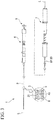
- Fig. 3 is an overall diagram showing an indwelling device 1 according to this embodiment.
- the indwelling device 1 is a device for indwelling the tissue-fastening tool 2 in a body using an endoscope.
- the indwelling device 1 includes a sheath 3, a needle tube (an elongated shaft and a treatment part) 4, a stylet (a treatment part) 5, a main manipulation part (a manipulation part) 6, an auxiliary manipulation part (a second manipulation part) 7, and a manipulation transmission member (hereinafter simply referred to as a "transmission member" in some cases) 8.
- the sheath 3, the needle tube 4, the stylet 5, and the main manipulation part 6 are disposed on a central axis L of the sheath 3.
- the auxiliary manipulation part 7 is coupled to the main manipulation part 6 on the central axis L of the sheath 3.
- a "central axis" is used with a meaning including an extension line of the central axis L of the sheath 3 when the main manipulation part 6 and the auxiliary manipulation part 7 are disposed on the central axis L of the sheath 3.
- a lumen 31 which extends from a distal end thereof to a proximal end thereof is formed inside the sheath 3 and the needle tube 4 is disposed in the lumen 31 so as to freely advance and retract.
- the proximal end side of the sheath 3 is connected to the main manipulation part 6.
- the sheath 3 is inserted into a treatment tool channel 102 of an endoscope insertion part 101 (refer to Fig. 21 ).
- Fig. 4 is a cross-sectional view of the distal end portion of the sheath 3.
- the sheath 3 includes a coil sheath part 301 and a tubular member 302 attached to a distal end portion of the coil sheath part 301.
- An inner diameter of the tubular member 302 constituting the distal end portion of the sheath 3 is larger than an inner diameter of the coil sheath part 301.
- a slit 33 extend substantially parallel to the central axis L from a distal end toward a proximal side of the tubular member 302 is formed by hollowing a part of an outer circumstantial surface of the tubular member 302.
- Fig. 5 is a diagram showing a shape of the slit 33. As shown in Fig. 5 , a circumferential edge of the slit 33 has a pair of regions, i.e., a first circumferential edge 331 and a second circumferential edge 332 which face each other in a circumferential direction of the sheath 3. The slit 33 communicates with a distal end opening of the sheath 3.
- a rotational direction of the sheath 3 at the time of indwelling the implant 2 that is, a direction in which the sheath 3 rotates when the stylet 5 advances is defined as a rotational direction (first direction) Dr1
- the first circumferential edge 331 is located on a downstream side in the rotational direction Dr1.
- the second circumferential edge 332 is located on an upstream side in the rotational direction Dr1.
- a protrusion 333 protrudes in a direction of the second circumferential edge 332, that is, in an upstream direction in the rotational direction Dr1.
- the second protrusion 334 protrudes in a direction of the first circumferential edge 331, that is, in a downstream direction of the rotational direction Dr1. That is to say, the protrusion 333 and the second protrusion 334 protrude to face each other.
- a width dimension of the slit 33 is reduced only on the distal end side of the sheath 3 due to the existence of the protrusion 333 and the second protrusion 334.
- a slit width of a portion having the protrusion 333 and the second protrusion 334 provided therein is larger than a diameter of the metal element wire of the implant 2. Therefore, the metal element wire are capable of passing into and out of the slit 33 between the protrusion 333 and the second protrusion 334.
- the needle tube 4 is a long member having a hollow needle tube insertion passage (an insertion passage) 41.
- the needle tube 4 is inserted into the lumen 31 to be projectable and retractable from the distal end of the sheath 3.
- a distal end (a puncturing part and a needle tip) 42 of the needle tube 4 is formed to be sharp and functions as a puncture needle.
- a proximal end of the needle tube 4 is attached to a distal end of a needle guide 67 (refer to Fig. 7A ), which will be described later, to be relatively rotatable and immovable forward and backward.
- the needle guide 67 freely rotates around the central axis L with respect to the needle tube 4 and fixed in a central axial direction with respect to the needle tube.
- a superelastic alloy represented by a nickel titanium alloy or stainless steel can be adopted, for example, as a material of the needle tube 4.
- the stylet 5 is a long core material, a distal end portion thereof is located in the needle tube insertion passage 41 (refer to Fig. 3 ), and a proximal end portion thereof extends to the main manipulation part 6 provided on the proximal end side of the sheath 3.
- the stylet 5 is a member which advances and retracts the tissue-fastening tool 2 with respect to the needle tube insertion passage 41.
- the stylet 5 is configured to be projectable and retractable from the distal end of the sheath 3.
- Fig. 8 is a cross-sectional view of the stylet 5 and a first cam tube (a cam tube) 61.
- a distal end engagement part 51 is provided at a distal end portion of the stylet 5.
- the distal end engagement part 51 includes a second engagement part main body 51a and a protruding part 51b.
- a proximal end portion of the second engagement part main body 51a has a cylindrical shape and a distal end portion thereof has a semi-cylindrical shape obtained by cutting a cylinder in half on the central axis L.
- the protruding part 51b is formed to protrude in a perpendicular direction from the planar part 51c of the second engagement part main body 51a parallel to the central axis L. As shown in Fig. 4 , when the planar parts 23a and 51c come into contact with each other in the needle tube 4 and the protruding part 51b is inserted into the recessed part 24, the distal end engagement part 51 and the implant-coupling part (a proximal end portion of the tissue-fastening tool 2) 22 engage with each other and the tissue-fastening tool 2 is coupled to the stylet 5.
- a stylet proximal end member 54 is fixed to a proximal end portion of the stylet 5.
- Three first engaging pins (cam followers, first projections, and a guided part) 55 are provided at a distal end portion of the stylet proximal end member 54 to protrude in an orthogonal direction (outward in a radial direction) with respect to the central axis L from an outer circumstantial surface thereof.
- the three first engaging pins 55 are each provided to be spaced apart at an equal angle in a circumferential direction and spaced apart at an equal interval in the direction of the central axis L.
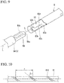
- Fig. 9 is a perspective view of the proximal end portion (a stylet proximal end member 54) of the stylet 5 and a distal end portion of a transmission member 8.
- a proximal end engagement part 56 is provided on the stylet proximal end member 54.
- the proximal end engagement part 56 is an engagement member which engages with the distal end portion of the transmission member 8.
- the proximal end engagement part 56 has a substantially flat plate shape and is provided to extend along the central axis L from a proximal end of the stylet proximal end member 54.
- a proximal end portion 56a of the proximal end engagement part 56 has a surface which protrudes toward a proximal end side.
- a through hole 56b is formed in the proximal end engagement part 56.
- the proximal end engagement part 56 has a size such that the proximal end engagement part 56 is located further inward than a maximum outer diameter part of the stylet 5 when viewed from the direction of the central axis L.
- the stylet 5 and the needle tube 4 are inserted through the lumen 31 of the sheath 3 so as to be coaxial with the central axis L of the sheath 3.
- the sheath 3, the needle tube 4, and the stylet 5 are members which are inserted into a body from a distal end side and are made of materials which are elastically deformable along with bending of the treatment tool channel 102 when inserted through the treatment tool channel 102 of an endoscope 100.
- the main manipulation part 6 is provided along the central axis L of the sheath 3 on the proximal end side of the sheath 3.
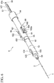
- Fig. 5 is a perspective view of the main manipulation part 6.
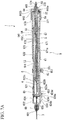
- Fig. 7A is a cross-sectional view of the main manipulation part 6.
- Fig. 7B is a cross-sectional view of a proximal end portion of the main manipulation part 6.
- Fig. 3 shows the main manipulation part 6 in a state in which a jig 9 to be described later is installed therein and Figs. 6 , 7A , 7B, and 7C show the main manipulation part 6 from which the jig 9 is removed.
- the main manipulation part 6 is provided to operate the sheath 3, the needle tube 4, and the stylet 5.
- the main manipulation part 6 includes the first cam tube 61, a main manipulation part main body 62, a sheath slider 63, a needle slider (a slider part or an elongated shaft manipulation part) 64, a needle slider stopper 65, a first rotation knob (an elongated shaft manipulation part and a first manipulation input part) 66, the needle guide (a guide part) 67, and a mounting part 69.
- the first cam tube 61 is a tube in which a first insertion passage 611 extending along the central axis L and a first guide passage (a cam, a guide passage, and a first helical groove) 612 are formed.
- the proximal end portion of the stylet 5 is inserted through the first cam tube 61.
- the first guide passage 612 communicates with an inside and outside of the tube and is formed in a helical shape.
- the helical shape of the first guide passage 612 is formed such that the first engaging pin 55 advances from a proximal end of the first guide passage 612 toward a distal end thereof while rotating right when viewed from the proximal end toward the distal end.
- Fig. 10 is a schematic view showing the helical shape of the first guide passage 612.
- the helical shape of the first guide passage 612 is formed at a constant pitch.
- a helical pitch P of the helical shape of the first guide passage 612 is set so that the sheath 3 rotates by less than one turn while a metal element wire of the proximal end side region 201b of the coil region 201 in the tissue-fastening tool 2 indwelled in a luminal organ on a proximal side is deployed for one turn.
- the helical pitch P is set so that the sheath 3 rotates more than one turn while the metal element wires constituting the coupling part 202 and the outer circumferential loop 203 are deployed for one turn.
- the number of helical turns (the number of turns) in the helical shape of the first guide passage 612 can be appropriately set in consideration of the number of turns and the like of the proximal end side region 201b in an indwelling shape of the tissue-fastening tool 2 within a range in which the helical pitch P satisfies the above-described conditions.
- the helical pitch P is longer than the length of one winding of the coil region 201 and shorter than any one of the length of one turn of the coupling part 202 and the length of one winding of the outer circumferential loop 203.
- the first guide passage 612 is set to a range in which a lead angle ⁇ is 20 degrees or more and 75 degrees or less.
- the stylet 5 and the stylet proximal end member 54 are inserted into the first cam tube 61.
- the first cam tube 61 and the three first engaging pins 55 of the stylet proximal end member 54 constitute a first helical mechanism 80.
- the first engaging pins 55 are slidably engaged in the first guide passage 612 of the first cam tube 61.
- the three first engaging pins 55 of the stylet proximal end member 54 are inserted into the first guide passage 612 to protrude outward from the first insertion passage 611.
- the stylet 5 and the stylet proximal end member 54 are configured to be supported by the first cam tube 61 and to advance and retract while rotating with respect to the first cam tube 61.
- the helical mechanism defines the motion of the stylet 5.
- a proximal end side of the first cam tube 61 and a distal end side of the Luer joint 57 are fixed to each other.
- the Luer joint 57 and the stylet 5 are configured to be relatively rotatable.
- the stylet 5 and the stylet proximal end member 54 can advance and retract in the direction of the central axis L while rotating with respect to the first cam tube 61 and the Luer joint 57.
- the needle guide 67 has a substantially cylindrical shape, and as shown in Fig. 7A , includes a needle guide insertion passage 671 which extends in the direction of the central axis L. As shown in Figs. 7D and 11 , on a side wall part 672 of the needle guide 67, a slit surface which forms guide slits 673 communicating an outside of the needle guide 67 with an inside of the needle guide insertion passage 671 is straightly formed in the direction of the central axis L.
- the three guide slits 673 are formed at equal intervals in a circumferential direction of the needle guide 67.
- the needle guide insertion passage 671 is formed with a small-diameter part 671a having a small opening diameter of the needle guide insertion passage 671 in a partial region in the direction of the central axis L.
- the opening diameter of the small-diameter part 671a is set to be slightly larger than an outer diameter of the first cam tube 61.
- a needle slider end member 643 is fixed to a proximal end of the needle slider 64.
- the needle guide 67 is sandwiched between the needle slider 64 and the needle slider end member 643 at a proximal end portion and is supported to be capable of only rotating with respect to the needle slider 64.
- the stylet 5, the stylet proximal end member 54, the first cam tube 61, and the Luer joint 57 are inserted into the needle guide insertion passage 671 to be advanceable and retractable with respect to the needle guide 67.
- the first cam tube 61 is inserted through the small-diameter part 671a of the needle guide 67, the first cam tube 61 is supported to be relatively advanceable, retractable, and rotatable on the central axis L in the needle guide insertion passage 671.
- the three first engaging pins 55 of the stylet proximal end member 54 are respectively engaged with the guide slits 673 one by one.
- the first engaging pins 55 is slidable in the guide slit 673. That is to say, the first engaging pins 55 is slidable in the first guide passage 612 and in the guide slit 673.
- the first cam tube 61 is supported to be capable of only advancing and retracting with respect to the needle slider 64.
- the first engaging pins 55 of the stylet proximal end member 54 are engaged with both the first guide passage 612 and the guide slit 673.
- the stylet 5 and the stylet proximal end member 54 advance and retract with respect to the needle slider 64 while rotating and the needle guide 67 is configured to only rotate with the stylet 5 and the stylet proximal end member 54.
- a motion in which the stylet 5 advances while rotating is referred to as a "helical motion" in some cases.
- the main manipulation part main body 62 has a substantially cylindrical shape and includes the second insertion passage 621 extending in the direction of the central axis L formed therein.
- a sheath guide 623 is inserted into a distal end side of the second insertion passage 621.
- the needle guide 67 is inserted into a proximal end side of the second insertion passage 621.
- the sheath guide 623 is rotatably supported with respect to the main manipulation part main body 62 near a distal end of the second insertion passage 621.
- a sheath fixing part 625 is fixed to a distal end side of the sheath guide 623 and has the proximal end of the sheath 3 fixed thereto.
- the sheath guide 623 is a substantially cylindrical member extending in the direction of the central axis L as shown in Fig. 7D and has a third insertion passage 623a formed therein as shown in Fig. 7A .
- the stylet 5 inserted through the needle guide 67 and the first cam tube 61 is inserted through the third insertion passage 623a to be advanceable and retractable.
- three first slits 623b straightly extending in the direction of the central axis L are formed at equal intervals in the circumferential direction.
- the first slits 623b are engaged with ribs 673a (refer to Fig.
- the sheath guide 623 rotates to follow the rotation due to a rotational torque transmitted from the needle guide 67.
- the sheath guide 623 does not follow the movement. From the above, the first helical mechanism 80 rotates the sheath 3 around the central axis L due to the engagement between the cam and each of the cam followers.
- the ring-shaped needle slider stopper 65 is externally installed on the main manipulation part main body 62.
- the needle slider stopper 65 has an inner diameter in which the needle slider stopper 65 is advanceable and retractable in the direction of the central axis L with respect to the main manipulation part main body 62.
- a screw hole 651 is formed in the needle slider stopper 65.
- a needle stopper screw 652 is screwed into the screw hole 651. When the needle stopper screw 652 is inserted and screwed into the screw hole 651, a distal end of the needle stopper screw 652 presses an outer circumstantial surface of the main manipulation part main body 62 and a position of the needle slider stopper 65 with respect to the main manipulation part main body 62 is fixed.
- the sheath slider 63 is provided on a distal end side of the main manipulation part main body 62. As shown in Figs. 6 and 12 , the sheath slider 63 is a cylindrical member and has a fourth insertion passage 632 extending in the direction of the central axis L from a proximal end opening 631 formed therein. A distal end portion of the main manipulation part main body 62 is inserted through the proximal end opening 631. The main manipulation part main body 62 is provided to be advanceable and retractable in the fourth insertion passage 632.
- the mounting part 69 is fixed to a distal end of the sheath slider 63.
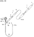
- the mounting part 69 is fixed to a manipulation part 104 of the endoscope 100 by being screw-engaged with a port 103 of the treatment tool channel 102 of the endoscope 100 (refer to Fig. 20 ).
- the main manipulation part 6 is fixed to the endoscope 100 by the mounting part 69.
- a distal end insertion passage 691 extending in the direction of the central axis L is formed in the mounting part 69.
- the sheath 3 is inserted through the distal end insertion passage 691 to be advanceable and retractable.
- the sheath 3 can be advanced and retracted by moving the main manipulation part main body 62 to advance and retract in a linear direction with respect to the sheath slider 63.
- a second slit 633 extending in the direction of the central axis L is formed in the sheath slider 63.
- a fixing knob 634 is inserted into the second slit 633 from an outer circumference side thereof.
- a screw part 634a of the fixing knob 634 passes through the second slit 633 and protrudes toward the fourth insertion passage 632 side of the sheath slider 63.
- a distal end of the screw part 634a of the fixing knob 634 is inserted into a screw hole 623d formed in an outer circumference of the distal end portion of the main manipulation part main body 62.
- the length of the screw part 634a is set such that a screw head 634b of the fixing knob 634 can be provided to be spaced apart slightly from the second slit 633 while maintaining a state in which a part of a distal end side of the screw part 634a is screwed into the screw hole of the main manipulation part main body 62.
- an amount of protrusion of the sheath 3 from the main manipulation part 6 is determined.
- the length of the second slit 633 in the direction of the central axis corresponds to an advancement and retraction movement length of the sheath 3.
- the sheath 3 is disposed at a maximally retracted position and the amount of protrusion of the sheath 3 from the distal end of the main manipulation part 6 is minimized.
- a resin spring 635 constituted of a cantilever extending in the direction of the central axis L is provided in a part of the second slit 633 of the sheath slider 63.
- an inclined surface 635a and a locking surface 635b are provided on the resin spring 635.
- the screw part 634a is disengaged from the inclined surface 635a when coming into contact with the distal end 633a of the second slit 633 and the resin spring 635 returns to an original position thereof. Even if a force returning the fixing knob 634 to a proximal end side in the direction of the central axis L acts in this state, the screw part 634a does not return because the screw part 634a comes into contact with the locking surface 635b. From the above, even if the screw part 634a is not screwed into the main manipulation part main body 62, the sheath slider 63 can be fixed while the amount of protrusion of the sheath 3 from the main manipulation part 6 is maximized.
- the needle slider 64 has a substantially cylindrical shape and is provided along the central axis L in an intermediate part of the main manipulation part 6 in the direction of the central axis L.
- the stylet 5 In a fifth insertion passage 641 formed in the needle slider 64, the stylet 5, the first cam tube 61, the needle guide 67, and the main manipulation part main body 62 are sequentially coaxially disposed from the central axis L side outward in the radial direction.
- the first rotation knob (the rotation knob) 66 which will be described later, is disposed at a proximal end portion of the needle slider 64.
- a pair of side holes 642 are formed at positions of an outer circumference of the needle slider 64 opposite to each other in the radial direction.
- a slide button unit 68 is provided in each of the pair of side holes 642. The slide button unit 68 is provided to switch between a state in which the needle slider 64 can advance and retract in the direction of the central axis L with respect to the main manipulation part main body 62 and a state in which the needle slider 64 can advance and retract while rotating about the central axis L.
- the slide button unit 68 in a state in which the needle slider 64 can advance and retract in the direction of the central axis L with respect to the main manipulation part main body 62 is shown at the lower side of Fig. 13A and the slide button unit 68 in a state in which the needle slider 64 can advance and retract while rotating about the central axis L with respect to the main manipulation part main body 62 is shown at the upper side of Fig. 13A .
- each of the pair of slide button units 68 is switched to one of a state shown at the upper side and a state shown at the lower side of Fig. 13A .
- a base body 681 is fitted into the side hole 642 and fixed to the needle slider 64 and a button main body 682 is attached to an outer surface 681 a of the base body 681 in a radial direction thereof.
- a spring member 683 is provided as a biasing member between the button main body 682 and the base body 681.
- the button main body 682 is biased in a direction in which the button main body 682 is away from the base body 681 outward in the radial direction by the spring member 683.
- the slide button unit 68 further includes a plate 684 between the button main body 682 and the base body 681.
- the plate 684 is disposed to extend in the direction of the central axis L and a substantially intermediate part of the plate 684 in the direction of the central axis L is fixed to the base body 681.
- a hole 681b formed along the central axis L is formed in the base body 681.
- a distal end portion of the plate 684 is engaged with a slit 682a of the button main body 682 and a proximal end portion of the plate 684 is disposed in the hole 681b of the base body 681.
- a first surface 684a of the plate 684 faces the button main body 682 and a second surface 684b is located in the hole 681b and provided to face the main manipulation part main body 62.
- a locking pin (a locking part) 684c is provided at a proximal end portion of the plate 684 to protrude from the second surface 684b in a thickness direction of the plate 684 (inward in a radial direction of the base body 681).
- a helical groove (a second helical groove) 622 is formed in an outer circumstantial surface of an intermediate region of the main manipulation part main body 62 in the direction of the central axis L, and as shown in Fig. 13A , the locking pin 684c is switched between a state in which the locking pin 684c is engaged with the helical groove 622 and a state in which the locking pin 684c is not engaged with the helical groove 622.
- Fig. 13B is a cross-sectional view of the main manipulation part main body 62 taken along line B-B of Fig. 13A .
- a step is formed at a proximal end portion of the helical groove 622 so that an oblique portion 622a and a dent portion 622b are adjacent to each other.
- the dent portion 622b is formed at the proximal end of the helical groove 622 and the oblique portion 622a is formed closer to the distal end side of the helical groove 622 than the dent portion 622b so as to be continuous with the dent portion 622b.
- the oblique portion 622a is curvilinearly or linearly formed such that a groove depth of the helical groove 622 is gradually reduced toward the dent portion 622b and has a shallowest groove (a shallowest groove portion 622c) that is continuous with the dent portion 622b.
- the dent portion 622b is dented such that the groove depth sharply increases at a boundary between the dent portion 622b and the shallowest groove portion 622c. That is to say, an inner wall surface of the dent portion 622b at the boundary between the dent portion 622b and the shallowest groove portion 622c has an inclined angle larger than that of an inclined surface 622a in a helical direction following the helical groove 622.
- the dent portion 622b, the oblique portion 622a, and the locking pin 684c constitute a needle anti-movement mechanism.
- the needle anti-movement mechanism is configured to prevent movement of the locking pin 684c by the dent portion 622b and the oblique portion 622a.
- the distal end portion of the plate 684 is pressed toward the main manipulation part main body 62 side. Accordingly, the proximal end portion of the plate 684 moves away from the main manipulation part main body 62 and the locking pin 684c is detached from the helical groove 622.
- the distal end portion of the plate 684 is pulled outward in the radial direction by the button main body 682 and the proximal end portion of the plate 684 is biased toward the main manipulation part main body 62 side.
- the locking pin 684c is fitted into the helical groove 622 formed in the outer circumstantial surface of the main manipulation part main body 62.
- the needle slider 64 is configured to be advanceable and retractable with respect to the main manipulation part main body 62 while rotating along the helical groove 622.
- the locking pin 684c is capable of being moved to the proximal end of the helical groove 622 when the operator manipulates the needle slider 64 in a state in which the locking pin 684c is fitted into the helical groove 622. Therefore, the locking pin 684c passes over the oblique portion 622a and is fitted into the dent portion 622b in accordance with a manipulation of the needle slider 64 by the operator. In a state in which the locking pin 684c is fitted into the dent portion 622b, the locking pin 684c is biased toward the main manipulation part main body 62 side by the spring member 683.
- the needle slider 64 is not capable of being advanced while rotating along the helical groove 622. That is to say, the locking pin 684c is locked in a helical direction of the helical groove 622 and the movement of the needle slider 64 with respect to the main manipulation part main body 62 is prevented.
- the first rotation knob 66 is a member that is rotationally manipulated by the operator when the tissue-fastening tool 2 is sent from the distal end of the needle tube 4. As shown in Figs. 6 , 7A , 7B, and 7C , the first rotation knob 66 is a cylindrical member and is attached to cover a side surface and a proximal end side of the needle slider end member 643. The first rotation knob 66 is rotatably attached to the needle slider end member 643. A female screw 661 is formed at a center of the first rotation knob 66 and is screwed to a male screw 572 which is cut in an outer circumference of the Luer joint 57.
- An engaging projection 643b that protrudes in the radial direction is formed in a through hole 643a at a substantially center of the needle slider end member 643.
- a linear groove 573 extending in the direction of the central axis L is formed in the outer circumference of the Luer joint 57.
- the engaging projection 643b is engaged with the linear groove 573.
- Fig. 14 is a side view of the auxiliary manipulation part 7 when viewed from a direction orthogonal to the central axis L.
- the auxiliary manipulation part 7 is disposed to be separated from the main manipulation part 6 and is connected to the main manipulation part 6 via the transmission member 8.
- the main manipulation part 6 and the auxiliary manipulation part 7 are configured to be separably connected to each other via the transmission member 8.
- the auxiliary manipulation part 7 advances and retracts the transmission member 8 to manipulate the movement of the stylet 5 in the main manipulation part 6.
- the auxiliary manipulation part 7 includes a manipulation coupling part 71, an auxiliary manipulation part main body 72, a second cam tube 73, and a rotation handle (a second manipulation input part) 74 in order from a distal end side thereof and the transmission member 8 is inserted throughout the entire length in the direction of the central axis L.
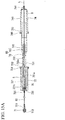
- Fig. 15A is a cross-sectional view of the auxiliary manipulation part 7 in a plane passing through the central axis L.
- Fig. 15B is a cross-sectional view of the manipulation coupling part 71.
- the manipulation coupling part 71 is a member that is the proximal end portion of the main manipulation part 6 and couples the proximal end portion of the stylet 5 to the distal end portion of the transmission member 8.
- a sixth insertion passage 711 extending in the direction of the central axis L is formed in the manipulation coupling part 71.
- a screw groove 712 capable of being screwed to a flange 574 of the Luer joint 57 (refer to Fig. 6 ) is formed around the central axis L on an inner circumferential surface of a distal end portion of the sixth insertion passage 711.
- the transmission member 8 is a core material which is long and has flexibility (a flexible member). A distal end side from a substantially central part of the transmission member 8 in the direction of the central axis L is inserted into a cable tube 81 having flexibility.
- the transmission member 8 is a transmission member that transmits a manipulation input of the rotation handle 74 on the auxiliary manipulation part 7 to the main manipulation part 6.
- a stylet engagement part 82 is provided at the distal end of the transmission member 8.
- the stylet engagement part 82 includes two arms 82b extending in parallel with the direction of the central axis L from a base part 82a having a substantially cylindrical outer shape.
- the two arms 82b include planar parts 82c and 82d that face each other across the central axis L.
- a separation distance between the planar parts 82c and 82d in the radial direction (a direction orthogonal to the central axis L) is set to be slightly larger than a plate thickness of the proximal end engagement part 56 of the main manipulation part 6.
- the transmission member 8 is inserted into the sixth insertion passage 711 to be advanceable, retractable, and rotatable with respect to the manipulation coupling part 71.
- the distal end of the transmission member 8 is disposed at a substantially intermediate part of the sixth insertion passage 711 in the direction of the central axis L.
- the stylet engagement part 82 is configured so that the stylet 5 and the transmission member 8 are engaged with each other when the proximal end engagement part 56 is inserted between the two arms 82b on the central axis L.
- the planar parts 82c and 82d come into contact with the proximal end engagement part 56 and the rotational motion of the transmission member 8 can be transmitted to the stylet 5.
- the stylet 5 can advance when the transmission member 8 advances.
- the auxiliary manipulation part main body 72 has a tubular shape and is disposed on a distal end side of the auxiliary manipulation part 7. As shown in Fig. 15A , a seventh insertion passage 721 extending in the direction of the central axis L is formed in the auxiliary manipulation part main body 72.
- the seventh insertion passage 721 includes a first region 721a on a proximal end side thereof and a second region 721b which is located closer to a distal end side thereof than the first region 721a and has an opening diameter smaller than an opening diameter of the first region 721a.
- a first ring member 723 is externally installed onto an outer circumstantial surface of a proximal end portion of the auxiliary manipulation part main body 72 and fixed to the outer circumstantial surface thereof by a screw 724.
- a connector 725 is fixed to a distal end portion of the auxiliary manipulation part main body 72.
- the connector 725 is inserted to block a distal end opening of the second region 721b of the seventh insertion passage 721 and fixed to the auxiliary manipulation part main body 72.
- An eighth insertion passage 726 is formed in the connector 725 along the central axis L and a distal end portion of a guide tube 75 to be described later is fixed to a proximal end side of the eighth insertion passage 726.
- the cable tube 81 is fixed to a distal end side of the eighth insertion passage 726.
- the transmission member 8 is inserted into the guide tube 75 and the cable tube 81 fixed in the eighth insertion passage 726 and extends to the manipulation coupling part 71.
- the second cam tube 73 is a long tubular member and includes a second guide passage (a fourth helical groove) 731 constituted of a groove formed around the central axis L in a helical shape and distal and proximal end portions of the second guide passage 731 which are formed on an outer circumstantial surface thereof.
- a second guide passage 731 of the second cam tube 73 and the first guide passage 612 of the first cam tube 61 are formed at the same helical pitches P1 and P2 and in the same rotational direction.
- a distal end side of the second cam tube 73 is inserted through the first region 721a of the seventh insertion passage 721 of the auxiliary manipulation part main body 72 and a distal end portion of the second cam tube 73 is fixed to the second region 721b.
- the second cam tube 73 has a fitting hole 733 at a region in the outer circumstantial surface of the second cam tube 73 between grooves of the second guide passage 731.
- the fitting hole 733 is a hole formed through a wall surface of the second cam tube 73 such that a rod-like member 734 such as a split pin or a screw is fitted therein.
- the fitting hole 733 is formed to be exposed at a position closer to the distal end side of the second cam tube 73 than the distal end of the rotation handle 74 when the rotation handle 74 is moved to the extreme proximal end side, that is, when the second engaging pin 743 (to be described below) comes into contact with an end portion of the second guide passage 731 of the second cam tube 73. For this reason, as shown in Fig. 14 , in the state in which the rotation handle 74 (to be described later) is moved to the extreme proximal end side, the rotation handle 74 cannot be moved forward due to the rod-like member 734 such as a split pin or a screw inserted into the fitting hole 733.
- the rod-like member 734 such as a split pin or a screw inserted into the fitting hole 733.
- a gap S is formed between an inner circumferential surface of the first region 721a and an outer circumstantial surface of the second cam tube 73.
- the second cam tube 73 has a cam insertion passage 732 extending in the direction of the central axis L.
- a reduced diameter part 732a in which an opening diameter is reduced in a substantially central part in the direction of the central axis L is formed in the cam insertion passage 732.
- the guide tube 75 having a length substantially equal to that of the second cam tube 73 is inserted into the cam insertion passage 732.
- a distal end portion of the guide tube 75 is fixed to the eighth insertion passage 726 of the connector 725 as described above. Since a proximal end side of the guide tube 75 is inserted through the reduced diameter part 732a of the cam insertion passage 732, the guide tube 75 is disposed so that a center thereof coincides with the central axis L.
- the transmission member 8 is inserted in the guide tube 75 to be advanceable and retractable. With this constitution, the transmission member 8 is supported on the central axis L to be advanceable and retractable in the auxiliary manipulation part 7.
- the rotation handle 74 is a tubular member and is disposed at a proximal end portion of the auxiliary manipulation part 7.
- a ninth insertion passage 741 extending in the direction of the central axis L is formed by an inner circumferential surface thereof.
- An opening diameter of a distal end side region of the ninth insertion passage 741 is set to be slightly larger than an outer diameter of the second cam tube 73.
- Three screw holes 742 communicating from an outer circumstantial surface of the rotation handle 74 into the ninth insertion passage 741 are formed at a distal end portion of the rotation handle 74 (two screw holes 742 are not shown in Fig. 15A ).
- the screw holes 742 are provided at equal intervals in the circumferential direction at every 1/3 turn (an angle of 120 degrees) and is provided at equal intervals in the longitudinal direction at every 1/3 length of the aforementioned helical pitch.
- the second cam tube 73 is inserted into the ninth insertion passage 741.
- the second engaging pin (the second engaging part) 743 is screwed and fixed to each of the screw holes 742.
- Each of the screw holes 742 protrudes into the ninth insertion passage 741 when protruding inward in the radial direction from the inner circumferential surface of the rotation handle 74 and the second engaging pin 743 is slidably engaged in the second guide passage 731.
- An outer diameter of a distal end portion of the second engaging pin 743 is smaller than an opening width of the second guide passage 731.
- the distal end portion of the second engaging pin 743 is configured to be relatively movable in the second guide passage 731 in accordance with the rotation of the rotation handle 74.
- the second cam tube 73 and the second engaging pin 743 constitute a second helical mechanism 90.
- a fixing member 744 that covers a proximal end opening of the ninth insertion passage 741 is fixed to a proximal end portion of the rotation handle 74.
- the proximal end portion of the transmission member 8 and the proximal end portion of the rotation handle 74 are fixed to each other by the fixing member 744. Therefore, the proximal end portion of the transmission member 8 follows the manipulation of the rotation handle 74. That is to say, the second helical mechanism 90 advances the transmission member 8 while rotating the transmission member 8 with respect to the auxiliary manipulation part main body 72.
- a second ring member 745 is externally installed onto an outer circumstantial surface of a substantially central part of the rotation handle 74 in the direction of the central axis L and fixed to the outer circumstantial surface thereof by a screw 746.
- An outer diameter of the rotation handle 74 on a position closer to a distal end side than the second ring member 745 is set to be slightly smaller than the opening diameter of the first region 721a of the seventh insertion passage 721.
- the main manipulation part 6 can perform various manipulations such as advancement, retraction, and rotation of the sheath 3, advancement and retraction of the needle tube 4, and advancement, retraction, and rotation of the stylet 5.
- the auxiliary manipulation part 7 is configured such that advancement, retraction, and rotational manipulation of the transmission member 8 can be performed and manipulation on the needle tube 4 cannot be performed.
- a procedure of installing the indwelling device 1 in an ultrasonic endoscope (hereinafter referred to as an "endoscope"), passing the tissue-fastening tool 2 through the duodenal tissue D and the common bile duct tissue CBD, and indwelling the tissue-fastening tool 2 will be described below as an example.
- Fig. 17 is a flowchart showing the procedure of this embodiment.
- the indwelling device 1 is configured such that a motion (a first motion) of the stylet 5 that moves from the proximal end side to the distal end side with respect to the needle tube 4 is capable of being manipulated by both of the main manipulation part 6 and the auxiliary manipulation part 7. Furthermore, the stylet 5 has a first state in which the stylet 5 is advanced straight with respect to the needle tube 4 and the sheath 3 until the entire distal end side region 201a of the coil region 201 of the implant 2 protrudes from the needle tube 4. Furthermore, the stylet 5 has a second state in which the stylet 5 is advanced straight while rotated until the entire proximal end side region 201b of the coil region 201 protrudes from the needle tube 4.
- a maximum movable amount of the stylet 5 (a maximum movable amount of the stylet 5 in the first state) in a direction along the longitudinal axis of the sheath 3 due to the main manipulation part 6 (the first rotation knob 66) may be set to be smaller than a maximum movable amount of the stylet 5 (a maximum movable amount of the stylet 5 in the second state) in a direction along the longitudinal axis of the sheath 3 due to the manipulation of the auxiliary manipulation part 7 (the rotation handle 74).
- the indwelling device 1 is configured such that manipulation (a second motion) of the needle tube 4 is performed only by the main manipulation part 6. This will be described in detail below.
- Fig. 18 is a side view showing an initial state of the main manipulation part 6.
- the tissue-fastening tool 2 in the tissue-fastening tool 2, the distal end portion of the stylet 5 and the proximal end portion of the tissue-fastening tool 2 are engaged with each other in the needle tube insertion passage 41 of the distal end portion of the needle tube 4 inserted into the sheath 3.
- the tissue-fastening tool 2 is provided to be projectable and retractable from the distal end of the needle tube 4. As shown in Fig.
- a part of the tissue-fastening tool 2 located on a side closer to the distal end side than the coupling part with the stylet 5 protrudes from the distal end of the needle tube 4 and is disposed in a state in which the part thereof is restored to an indwelling shape.
- the main manipulation part 6 is packed as a product in a state in which the jig 9 is inserted from the proximal end side thereof.
- the state in which the tissue-fastening tool 2 is loaded in the needle tube 4 throughout the entire length thereof is set as a packing state, a state in which the tissue-fastening tool 2 extends by the needle tube 4 continues for a long period of time.
- a restoring force applied to the tissue-fastening tool 2 in advance to a coiled curved shape thereof is likely to weaken.
- the tissue-fastening tool 2 is independently packed separately from the main manipulation part 6, it is necessary for the user to perform a task of coupling the proximal end portion of the tissue-fastening tool 2 and the distal end portion of the stylet 5.
- the tissue-fastening tool 2 is a very small member, the coupling task requires skill and time.
- the packing is performed in a state in which only the proximal end portion of the tissue-fastening tool 2 engaged with the stylet 5 is inserted into the needle tube 4 and other regions is located outside of the needle tube 4.
- This state is referred to as an initial state in this description.
- An example of a procedure for setting the initial state will be described below.
- the initial state (packing state) is set by the protruding part 51b being engaged with the recessed part 24 of the tissue-fastening tool 2 and by the stylet 5 being moved to the proximal end side to store the distal end engagement part 51 in the needle tube 4.
- a connection state between the tissue-fastening tool 2 and the stylet 5 is maintained. At this time, a motion of pulling the stylet 5 using the jig 9 is performed.
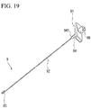
- Fig. 19 is a perspective view showing the jig 9.
- the jig 9 includes a jig handle 91, a rod-like insertion shaft (a shaft) 92, a jig side coupling part 93, and a shaft head 95.
- the insertion shaft 92 is fixed to a distal end side of the shaft head 95.
- a hole having a diameter slightly larger than that of the insertion shaft 92 and smaller than that of the shaft head 95 is opened and has the insertion shaft 92 inserted therein.
- the jig side coupling part 93 has a hook shape which is curved from a distal end of the insertion shaft 92 and extends toward a proximal end side thereof.
- the jig handle 91 is provided to be relatively rotatable with respect to the insertion shaft 92.
- a tubular jig stopper 94 is externally installed onto an outer circumference of a proximal end portion of the insertion shaft 92.
- the jig side coupling part 93 is locked to the through hole of the proximal end engagement part 56 in the first cam tube 61. That is to say, the tissue-fastening tool 2 and the jig 9 are connected to each other via the stylet 5.
- the proximal end engagement part 56 is disposed on the distal end side of the first cam tube 61.
- the insertion shaft 92 passes in the first cam tube 61 and extends toward the proximal end side and the jig handle 91 is exposed to the proximal end side of the main manipulation part 6. It should be noted that, at this time, the jig stopper 94 is not externally installed onto the insertion shaft 92.
- the insertion shaft 92 has a length that is greater than or equal to a length from the proximal end engagement part 56 to the proximal end of the Luer joint 57 when the stylet 5 is located at the extreme distal end side with respect to the needle tube 4.
- the distal end of the stylet 5 is exposed to the outside of the needle tube 4 as described above, the distal end of the stylet 5 is engaged with the tissue-fastening tool 2.
- the proximal end portion of the tissue-fastening tool 2 is drawn into the needle tube 4 by pulling the jig 9 slightly toward the proximal end side to set the initial state.
- the jig 9 is prevented from moving to the distal end side by installing the jig stopper 94.
- the jig stopper 94 can be externally installed onto the insertion shaft 92 from a side thereof.
- the initial state (the packing state) is completed. After being sterilized by a manufacturer, a product is shipped.
- Step S1 the user performs a preparatory process (Step S1) of pulling and entirely putting the tissue-fastening tool 2 into the needle tube 4.
- the user refers to an operator and an assistant who assists a treatment of the operator.
- the preparatory process may be performed by the operator or by the assistant.
- a rotational direction when the user performs a rotational manipulation of each part of the main manipulation part 6 and the auxiliary manipulation part 7 is represented by a rotational direction viewed from the proximal end to the distal end in the direction of the central axis L.
- the user rotates the first rotation knob 66 of the main manipulation part 6 in a right direction.
- the Luer joint 57 and the first cam tube 61 fixed to the Luer joint 57 move to the proximal end side.
- the first engaging pins 55 of the stylet 5 is engaged with both the first guide passage 612 and the guide slit 673 of the needle guide 67, when the first cam tube 61 moves toward the proximal end side, the stylet 5 also moves toward the proximal end side. As a result, the tissue-fastening tool 2 is pulled toward the proximal end side in the needle tube 4.
- first rotation knob 66 When the user continues to rotate first rotation knob 66 right, the female screw 661 comes into contact with a distal end side terminal of the male screw 572 of the Luer joint 57 screwed into the female screw 661, the first rotation knob 66 cannot rotate any more, and the movement of the Luer joint 57 to the proximal end side cannot be performed. Thus, the user perceives that the substantially intermediate part of the tissue-fastening tool 2 in the longitudinal direction has been drawn into the needle tube 4.
- the tissue-fastening tool 2 is drawn into the needle tube 4 using the jig 9.
- a pulling force in a proximal end direction acts on the stylet 5.
- the stylet 5 moves toward the proximal end side while rotating and the tissue-fastening tool 2 is further drawn into the needle tube 4.
- the jig handle 91 is provided to be relatively rotatable with respect to the insertion shaft 92.
- the insertion shaft 92 relatively rotates with respect to the jig handle 91 to follow the rotation of the stylet 5.
- the needle guide 67 is simultaneously rotated. Since the tissue-fastening tool 2 generates a strong force to return to an original coil shape thereof by being drawn into the needle tube 4, the needle tube 4 receives the strong force from the tissue-fastening tool 2.
- the movement of the needle tube 4 in the rotational direction may be made to follow the movement of the tissue-fastening tool 2 in order to easily draw the tissue-fastening tool 2 into the needle tube 4.
- the needle tube 4 is attached to the needle guide 67 to be relatively rotatable and not to be advanceable and retractable.
- the tissue-fastening tool 2 can be loaded into the needle tube 4 while rotating due to the motion of pulling the jig handle 91 toward the proximal end side in a linear direction along the central axis L.
- the tissue-fastening tool 2 is gradually stored in the needle tube 4 and one of the first engaging pins 55 that is disposed closest to the proximal end side comes into contact with an end face on the distal end side of the Luer joint 57 immediately after the distal end of the tissue-fastening tool 2 is stored in the needle tube 4.
- the stylet 5 can no longer move toward the proximal end side and the jig 9 can no longer be drawn toward the proximal side.
- the user perceives that the loading of the tissue-fastening tool 2 has been completed.
- the proximal end engagement part 56 since the proximal end engagement part 56 is exposed to the outside, the operator releases the engagement between the jig 9 and the proximal end engagement part 56 to detach the jig 9.
- the preparatory process is completed.
- the tissue-fastening tool 2 is loaded using the jig 9, it is not required to provide a mechanism for drawing the tissue-fastening tool 2 into the needle tube 4 in the main manipulation part 6 and it is possible to reduce a size of the main manipulation part.
- Step S2 the main manipulation part 6 is installed in the endoscope 100 and fixed thereto.
- the sheath 3 and the needle tube 4 are inserted into the treatment tool channel 102 of the endoscope insertion part 101, and as shown in Fig. 20 , the main manipulation part 6 is fixed to the manipulation part 104 of the endoscope 100 by screw-engaging the mounting part 69 provided at the distal end of the sheath slider 63 of the main manipulation part 6 with the port 103 of the treatment tool channel 102 of the endoscope 100.
- the operator and the assistant cooperate to perform the manipulation.
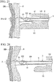
- Figs. 21 to 27 are diagrams showing aspects on the distal end side of the endoscope insertion part 101 when using the indwelling device 1.
- the operator inserts the endoscope insertion part 101 into a treatment target site in a body (Step S3).
- a distal end of the endoscope insertion part 101 is inserted into the vicinity of the duodenal tissue D which is a target tissue.
- Steps S2 and Step S3 may be performed in reverse order.
- Step S4 a position of the distal end of the sheath 3 with respect to the distal end of the endoscope insertion part 101 is adjusted (Step S4).
- the operator loosens the fixing knob 634, advances and retracts the main manipulation part main body 62 in the direction of the central axis L with respect to the sheath slider 63, and performs adjustment so that the position of the distal end of the sheath 3 in the direction of the central axis L is at a predetermined position with respect to the distal end of the endoscope insertion part 101.
- Fig. 21 shows a state in which the distal end position of the sheath 3 in the direction of the central axis L coincides with the distal end of the endoscope insertion part 101.
- the operator brings the endoscope insertion part 101 and the distal end opening portion 32 of the sheath 3 into contact with the duodenal tissue D.
- An ultrasonic transducer 101a is provided at the distal end of the endoscope insertion part 101. For this reason, in a subsequent treatment, a state in which the distal end of the endoscope insertion part 101 is in contact with the duodenal tissue D is maintained and the operator performs the treatment while checking an ultrasonic image.
- an amount of protrusion of the needle tube 4 from the distal end opening portion 32 of the sheath 3 in the direction of the central axis L is set (Step S5).
- the needle slider stopper 65 can slide.
- the operator After sliding the needle slider stopper 65 toward the distal end side depending on a length (an amount of protrusion of the needle tube 4 from the sheath 3) by which the puncturing part 42 of the needle tube 4 is desired to puncture into the tissue, the operator tightens the needle stopper screw 652 to fix the needle slider stopper 65.
- a puncture length of the puncturing part 42 of the needle tube 4 is set.
- the movement of the needle slider 64 is restricted by the slide button unit 68 and the needle slider 64 does not move linearly.
- the puncturing part 42 of the needle tube 4 punctures the target tissue (Step S6).
- the button main body 682 of the slide button unit 68 toward the central axis L side, a restriction of an advancement and retraction movement of the needle slider 64 is released and the needle slider 64 enters a state of being advanceable and retractable in the direction of the central axis L with respect to the main manipulation part main body 62.
- the operator advances the needle slider 64 in a linear direction until the needle slider 64 comes into contact with the needle slider stopper 65.
- the needle tube 4 advances straight with the advancement of the needle slider 64.
- the puncturing part 42 of the needle tube 4 protrudes from the distal end of the sheath 3 and punctures the duodenal tissue D and the common bile duct tissue CBD, which are target tissues.
- the slide button unit 68 moves in a direction in which the button main body 682 is separated from the outer side of the needle slider 64 in the radial direction by a biasing force of the spring member 683 and the locking pin 684c is pressed against an outer surface of the main manipulation part main body 62.
- Step S7 the tissue-fastening tool 2 is indwelled into a common bile duct side.
- the tissue-fastening tool 2 is caused to protrude from the needle tube 4.
- the operator rotates the first rotation knob 66 left.
- the needle slider 64 is also rotated left with the first rotation knob 66 until the locking pin 684c of the plate 684 is engaged with the helical groove 622 of the main manipulation part main body 62.
- the needle slider 64 Shortly, when the locking pin 684c is engaged with the helical groove 622, although the needle slider 64 about to advance toward the distal end side while rotating along the helical groove 622, the needle slider 64 neither rotates nor advances because the needle slider 64 is in contact with the needle slider stopper 65. For this reason, after the locking pin 684c is engaged with the helical groove 622, only the first rotation knob 66 is rotated. When the first rotation knob 66 is rotated with respect to the needle slider 64, the Luer joint 57 and the first cam tube 61 are linearly sent to the distal end side. At this time, the end face of the Luer joint 57 on the distal end side thereof and one of the first engaging pins 55 on the extreme proximal end side come into contact with each other.
- the stylet 5 is linearly sent to the distal end side while causing the first engaging pins 55 to slide along a slit surface of the guide slit 673 by pushing out the first engaging pins 55 by a distal end face of the Luer joint 57.
- a distal end side region 201a of a coil of the tissue-fastening tool 2 is linearly sent from the distal end of the needle tube 4 into the common bile duct.
- the stylet 5 linearly advances the distal end side region 201a of the tissue-fastening tool 2 in the needle tube 4 without rotating the distal end side region 201a so that the distal end side region 201a is capable of being sent from the distal end 42 of the needle tube 4 into the common bile duct.
- the Luer joint 57 When a proximal end side end face of the linear groove 573 of the Luer joint 57 comes into contact with a proximal end side end face of the engaging projection 643b of the needle slider end member 643 in time, the Luer joint 57 does no longer move toward the distal end side and the first rotation knob 66 does not rotate. That is to say, the proximal end side end face of the linear groove 573 of the Luer joint 57 functions as a restriction portion for restricting the rotation due to the first rotation knob 66.
- a length in the direction of the central axis L between the proximal end side end face of the linear groove 573 of the Luer joint 57 and the proximal end side end face of the engaging projection 643b of the needle slider end member 643 is set depending on a length of the metal element wire constituting the distal end side region 201a of the tissue-fastening tool 2.
- the operator can perceive that the process of indwelling the metal element wire of the tissue-fastening tool 2 on the common bile duct side by an amount of the distal end side region 201a is completed.
- the needle tube 4 is removed from the common bile duct tissue CBD and the duodenal tissue D (Step S8).
- the needle tube 4 is removed, as the distal end of the needle tube 4 is pulled out of the common bile duct tissue CBD, the distal end side region 201a of the tissue-fastening tool 2 is inclined and a circumferential direction of the coil comes into close contact with the common bile duct tissue CBD.
- the distal end side region 201a is inclined in a direction different from a predetermined direction of the coil.
- the tissue-fastening tool 2 When the distal end side region 201a is inclined in the different direction, the tissue-fastening tool 2 is not in an ideal indwelling mode, but a state of the coil on the common bile duct side cannot be visually recognized. Thus, a manipulation of correcting a direction of the distal end side region 201a to the predetermined direction is necessarily performed.
- the operator rotates the needle slider 64 right. Since the locking pin 684c of the plate 684 is engaged with the helical groove 622 of the main manipulation part main body 62, when the needle slider 64 is rotated right, the needle slider 64 moves toward the proximal end side while rotating along the helical groove 622.
- the Luer joint 57 and the first cam tube 61 also moves toward the proximal end side together with the needle slider 64 while rotating right. Since the first guide passage 612 of the first cam tube 61 is formed in a right screw direction, an inner surface of the first guide passage 612 imparts a vector force in a direction of the proximal end side to the first engaging pins 55 of the stylet 5 due to a right rotation of the first cam tube 61.
- the locking pin 684c passes over the aforementioned oblique portion 622a and fitted into the dent portion 622b. For this reason, as long as the operator does not press the button main body 682 inward in the radial direction to be pushed in until the button main body 682 comes into contact with the base body 681, the fitting of the locking pin 684c into the dent portion 622b is not capable of being intentionally released and the needle slider 64 is not capable of being advanced.
- the stylet 5 basically moves toward the proximal end side while rotating right together with the needle slider 64.
- the needle guide 67 also moves toward the proximal end side while rotating right together with the needle slider 64. Since the needle tube 4 is rotatably supported by the needle guide 67, the needle tube 4 moves toward the proximal end side together with the needle slider 64, but the movement of the needle tube 4 in the rotational direction is not related to the needle slider 64.
- the needle tube 4 inserted into the treatment tool channel 102 is also curved in a complex shape.
- a material of the needle tube 4 is a metal and it is difficult to perform a manipulation which rotates the needle tube 4 in a state of being curved in the complex shape because a very strong force is necessary. For this reason, even if the needle slider 64 moves toward the proximal end side while rotating, the needle tube 4 is configured to only follow the movement toward the proximal end side without rotating.
- the sheath 3 is fixed to the sheath guide 623 via the sheath fixing part 625.
- the sheath guide 623 is rotatably supported by the main manipulation part main body 62.
- the first slits 623b of the sheath guide 623 is fitted onto the ribs 673a formed on a radial outside of the circumference of the guide slit 673 of the needle guide 67 to follow only the rotational direction.
- the sheath 3 and the stylet 5 rotate while the needle tube 4 is pulled back.
- a wire of the tissue-fastening tool 2 enters the slit 33 of the sheath 3.
- the sheath 3 rotates in a predetermined direction in a state in which the wire of the tissue-fastening tool 2 is locked to the slit 33, the distal end side region 201a indwelled on the common bile duct side rotates and the direction of the distal end side region 201a is corrected to a desired state.
- Step S8 the stylet 5 moves toward the proximal end side while rotating, and at the same time, the needle tube 4 moves toward the proximal end side without rotating.
- the stylet proximal end member 54 having the stylet 5 connected thereto receives, from the first cam tube 61, a vector in the direction of the proximal end side, the stylet 5 and the needle tube 4 are pulled back toward the proximal end side.
- the distal end side region 201a of the tissue-fastening tool 2 indwelled on the common bile duct side acts as an anchor and the tissue-fastening tool 2 simultaneously receives a pulling force in the distal end direction.
- a force by which the stylet 5 is pulled toward the proximal end side becomes stronger, there is a concern concerning a force by which the target tissue is sandwiched between the tissue-fastening tool 2 and the sheath 3 increasing and the tissue compressed with an excessive load.
- the indwelling device 1 in order to prevent an excessive load to the target tissue, when the force by which the target tissue is sandwiched between the tissue-fastening tool 2 and the sheath 3 becomes stronger, the synchronization of the stylet 5 with the movement of the needle slider 64 moving in the proximal end direction while rotating right is released and the force by which the target tissue is sandwiched between the tissue-fastening tool 2 and the sheath 3 is relieved.
- the first guide passage 612 imparts a vector force to the first engaging pin 55 of the stylet 5 in the direction of the proximal end side.
- a motion of automatically adjusting the load can be achieved by suitably setting the lead angle of the first guide passage 612. To be specific, the motion can be achieved by setting the lead angle with a range of 20 degrees to 75 degrees.
- the lead angle of the first guide passage 612 When the lead angle of the first guide passage 612 is smaller than 20 degrees, since the vector force in the direction of the proximal end side imparted to the first engaging pins 55 becomes stronger, forces are first balanced when the force in the distal end direction from the tissue-fastening tool 2 becomes very strong. Thus, the sandwiched tissue is likely to be damaged.
- the lead angle of the first guide passage 612 is larger than 75 degrees, since the vector force in the direction of the proximal end side imparted to the first engaging pins 55 becomes weaker, the forces are balanced in a state in which the force in the distal end direction from the tissue-fastening tool 2 is very weak. Thus, the stylet 5 is likely to be unable to be sufficiently pulled toward the proximal end side.
- the lead angle be in a range of 40 degrees or more. This is because the larger the lead angle is, the smaller the diameter of the first cam tube 61 can be set. By reducing the diameter of the first cam tube 61, it is possible to reduce the diameter and weight of the main manipulation part 6.
- Step S8 when the locking pin 684c moves to the proximal end of the helical groove 622, the needle slider 64 is not rotated. Thus, the operator can perceive that the needle tube 4 is removed from the tissue. It should be noted that, as described above, due to the needle anti-movement mechanism that prevents the needle slider 64 from being advanced while being rotated again, the needle slider 64 can be neither advanced nor retracted while being rotated.
- Step S9 the sheath 3, the needle tube 4, and the stylet 5 are advanced by a predetermined distance.
- the operator loosens the fixing knob 634 and advances the fixing knob 634 until the fixing knob 634 comes into contact with the distal end of the second slit 633.
- the main manipulation part main body 62 comes into contact with the distal end of the sheath slider 63. By this manipulation, the distal end portion of the sheath 3 protrudes from the distal end of the treatment tool channel 102.
- the mounting part 69 is fixed to the endoscope 100, the sheath 3 is extruded from the distal end of the endoscope insertion part 101 and the endoscope insertion part 101 relatively retracts and the distal end thereof is separated from the duodenal tissue D.
- a surgical field is imaged by an optical imaging device (not shown) provided at the distal end of the endoscope insertion part 101. The operator performs the treatment while checking the endoscopic image.
- Step S9 a force in a direction in which the main manipulation part main body 62 retracts toward the proximal end side is generated in the main manipulation part main body 62.
- the screw part 634a of the fixing knob 634 is pressed by the resin spring 635 of the sheath slider 63, it is possible to prevent the main manipulation part main body 62 from retracting.
- the main manipulation part main body 62 can no longer advance when the main manipulation part main body 62 comes into contact with the sheath slider 63, the operator can perceive that the main manipulation part main body 62 has been pushed to a predetermined position. Furthermore, since the main manipulation part main body 62 does not unintentionally move toward the proximal end side due to the function of the resin spring 635 even if the fixing knob 634 is not tightened, the position of the main manipulation part main body 62 does not deviate from the predetermined position.
- Step S10 The process of the next Step S10 is performed by the assistant and the operator cooperating. Manipulations in Step S11 and steps subsequent to Step S11 are performed when the assistant manipulates the auxiliary manipulation part 7. That is to say, the manipulation of sending the coil of the tissue-fastening tool 2 on the duodenum side is performed by the auxiliary manipulation part 7.
- the auxiliary manipulation part 7 is connected to the main manipulation part 6 (Step S10).
- the assistant holds the auxiliary manipulation part 7 and inserts the proximal end of the Luer joint 57 of the main manipulation part 6 into a distal end opening of the sixth insertion passage 711 of the manipulation coupling part 71.
- the screw groove 712 of the sixth insertion passage 711 and the flange 574 formed at the proximal end portion of the Luer joint 57 are screwed together and the main manipulation part 6 and the auxiliary manipulation part 7 are connected to each other.
- the rotation handle 74 is rotated right, the rotation handle 74 advances while rotating along the second guide passage 731 formed in the second cam tube 73.
- the transmission member 8 Since the transmission member 8 is fixed to the rotation handle 74 via the fixing member 744, the transmission member 8 advances while rotating right. Since the stylet engagement part 82 of the transmission member 8 advances while rotating, the stylet engagement part 82 comes into contact with the proximal end engagement part 56 of the stylet 5 in a short time. As shown in Fig. 9 , the proximal end portion 56a has a shape that protrudes toward the proximal end side on the central axis L. For this reason, in a state in which the stylet engagement part 82 of the transmission member 8 and the proximal end of the proximal end engagement part 56 of the stylet 5 come into contact with each other, the transmission member 8 advances while rotating. Thus, the proximal end engagement part 56 of the main manipulation part 6 is fitted and engaged between two arms 82b of the stylet engagement part 82 in time. Thereafter, the rotation and advancement driving of the transmission member 8 can be transmitted to the stylet 5.
- the fitting hole 733, into which the rod-like member 734 is insertable is exposed when the rotation handle 74 is moved to the extreme proximal end side. For this reason, the rod-like member 734 is fitted into the fitting hole 733 formed in the second cam tube 73, and thereby the rod-like member 734 is allowed to protrude outward in the radial direction of the second cam tube 73. Therefore, the rod-like member 734 is merely fitted into the fitting hole 733, and thereby the rotation handle 74 of the auxiliary manipulation part 7 can be prevented from being rotated unintentionally.
- the needle slider 64 is prevented from being advanced again by the aforementioned needle anti-movement mechanism. Therefore, for example, when the assistant manipulates the auxiliary manipulation part 7, the needle tube 4 is prevented from being pushed out to the distal end side unintentionally.
- the tissue-fastening tool 2 is indwelled closer to the proximal side than the duodenal tissue D (Step S11).
- the assistant rotates the rotation handle 74 right, the transmission member 8 advances while rotating right.
- the transmission member 8 is configured to advance while rotating with respect to the auxiliary manipulation part 7 and to protrude from the manipulation coupling part 71.
- a helical movement (a helical input) of the transmission member 8 is transmitted to the stylet 5.
- the first engaging pins 55 are separated from the distal end face of the Luer joint 57.
- the rotation handle 74 rotates the stylet 5 while advancing the stylet 5 with respect to the Luer joint 57, the first engaging pins 55 are rotated while engaged with the slit surface of the guide slit 673 in the rotational direction of the stylet 5.
- the first engaging pins 55 slide along the first guide passage 612 of the first cam tube 61.
- the proximal end side region 201b of the tissue-fastening tool 2 is advanced while being rotated and can be sent from the distal end of the needle tube 4 into the duodenum.
- the helical pitch PI of the first guide passage 612 of the first cam tube 61 is equal to the helical pitch P2 of the second guide passage 731 of the second cam tube 73. Furthermore, rotational directions of the first guide passage 612 and the second guide passage 731 are the same in that the rotational directions of the first guide passage 612 and the second guide passage 731 are a right direction.
- the main manipulation part 6 and the auxiliary manipulation part 7 are provided as separate bodies and the manipulation of the auxiliary manipulation part 7 is transmitted to the main manipulation part 6 via the transmission member 8. Furthermore, in consideration of manipulation properties when the main manipulation part 6 and the auxiliary manipulation part 7 are manipulated by different persons, the transmission member 8 has flexibility and has a long length in some cases.
- the indwelling device 1 since the first guide passage 612 and the second guide passage 731 are formed at the same helical pitch and in the same rotational direction, a rotational motion transmitted from the transmission member 8 can be adjusted to be the same rotational movement amount as the movement of the rotation handle 74 in the first guide passage 612. For this reason, an input in a helical direction generated by the rotational manipulation of the auxiliary manipulation part 7 is accurately output from the stylet 5 as a helical motion.
- Step S11 described above as shown in Fig. 27 , the tissue-fastening tool 2 enters the slit 33 of the sheath 3.
- the tissue-fastening tool 2 is sent from the needle tube 4 while being rotated by the sheath 3 and the stylet 5.
- the proximal end side region 201b is deployed along the central axis L and sent toward the bile duct side as it is. In this case, the tissue-fastening tool 2 is not restored to the correct indwelling shape.
- the tissue-fastening tool 2 is configured not to be detached from the slit 33 of the sheath 3
- the metal element wire of the proximal end side region 201b is capable of being reliably restored to the indwelling shape on the duodenum side regardless of the user's skill.
- the helical pitch P in the helical shape of the first guide passage 612 is set such that the sheath 3 rotates less than one turn while the metal element wire of the proximal end side region 201b indwelled in the luminal organ on the proximal side in the coil region 201 of the tissue-fastening tool 2 is being deployed for one turn. For this reason, the deployed metal element wire is biased to have a circular arc having a diameter larger than the diameter of the helical proximal end side region 201b of the first guide passage 612 in the indwelling shape (hereinafter, this phenomenon refers to the expression "unrolled").
- the unrolled metal element wire Since the unrolled metal element wire is biased to form a large-diameter circular arc, the unrolled metal element wire tend to move away from the central axis L, and as shown in Fig. 31 , the first circumferential edge 331 is pushed to come into contact with the first circumferential edge 331 located on the downstream side in the rotational direction Dr1 of the sheath 3.
- a force pushing the first circumferential edge 331 becomes stronger, there is a concern concerning the rotation of the sheath 3 which is not transmitted due to the biased metal element wire deviating to the outside of the slit 33, but the protrusion 333 is provided on the distal end side of the first circumferential edge 331 and thus the deviation of the biased metal element wire from the slit 33 is prevented.
- the proximal end side region 201b is deployed from the distal end side of the central axis L toward the proximal end side thereof and indwelled, but when the coupling part 202 and the outer circumferential loop 203 are sent from the sheath 3 and restored to the indwelling shape, unlike the proximal end side region 201b, the coupling part 202 and the outer circumferential loop 203 are deployed from the proximal end side of the central axis L toward the distal end side thereof. For this reason, in the coupling part 202, and the outer circumferential loop 203, the behavior at the time of shape restoration of the tissue-fastening tool 2 changes compared with that of the proximal end side region 201b.
- the metal element wire is likely to deviate from the slit 33, or the coupling part 202 and the outer circumferential loop 203 are tangled, thereby the tissue-fastening tool 2 is likely not to be restored to the indwelling shape.
- the helical shape of the first guide passage 612 is set such that the sheath 3 rotates one turn or more while the metal element wire constituting the coupling part 202 and the outer circumferential loop 203 is being deployed for one turn.
- the metal element wire sent from the sheath 3 is biased to have a circular arc having a radius of curvature smaller than radii of curvature of the coupling part 202 and the outer circumferential loop 203 in the indwelling shape (hereinafter, this phenomenon refers to the expression "rolled-tightened").
- the metal element wire When the metal element wire is rolled-tightened, a spring force of the coupling part 202 and the outer circumferential loop 203 strengthens. For this reason, the coupling part 202 and the outer circumferential loop 203 are not easily deformed so that a change in behavior at the time of shape restoration is reduced and thus the aforementioned occurrence of failure is suitably minimized. Since the rolled-tightened metal element wire is biased to form a circular arc having a smaller radius of curvature, the rolled-tightened metal element wire approaches the central axis L, and as shown in Fig.
- the rolled-tightened metal element wire comes into contact with the second circumferential edge 332 located on the upstream side in the rotational direction Dr1 of the sheath 3 to push the second circumferential edge 332.
- a force pushing the second circumferential edge 332 becomes stronger, there is a concern concerning the rotation of the sheath 3 which is not transmitted due to the biased metal element wire deviating to the outside of the slit 33, but the second protrusion 334 is provided on the distal end side of the second circumferential edge 332 and thus the deviation of the biased metal element wire from the slit 33 is prevented.
- Figs. 31 and 32 show a cross section of the tubular member 302 at a portion at which the first circumferential edge 331 and the second circumferential edge 332 are provided when viewed from the distal end side of the sheath 3.
- the amount of turn of the sheath 3 for achieving the aforementioned effects can be set as appropriate.
- an amount of turn of the sheath 3 until the metal element wire is deployed from the sheath 3 by a length of one turn of the proximal end side region 201b is preferably 0.5 turns or more and 0.9 turns or less.
- an amount of turn of the sheath 3 while the metal element wire constituting the coupling part 202 is being deployed for one turn is preferably more than 1 turn and 1.8 turns or less.
- the amount of turn of the sheath 3 is determined solely in accordance with the helical shape of the first guide passage 612.
- the amounts of protrusion of the protrusion 333 and the second protrusion 334 is a half or more of the diameter of the metal element wire constituting the tissue-fastening tool 2 is desirable, because the deviation of the metal element wire to the outside of the slit 33 can be suitably prevented.
- the needle tube 4 does not rotate as described above.
- the one of the first engaging pins 55 of the stylet 5 on the extreme distal end side comes into contact with the distal end of the first guide passage 612 of the first cam tube 61, the advancement of the stylet 5 is completed.
- the distal end of the stylet 5 is exposed to the outside of the needle tube 4.
- the engagement between the implant-coupling part 22 of the tissue-fastening tool 2 and the distal end engagement part 51 of the stylet 5 is released and the indwelling of the tissue-fastening tool 2 is completed.
- the indwelling device 1 is configured such that the distal end of the stylet 5 is exposed from the distal end of the needle tube 4 when both of the main manipulation part 6 and the auxiliary manipulation part 7 perform the motion (the first motion) in which the tissue-fastening tool 2 is discharged from the distal end of the needle tube 4 by the stylet 5 being advanced with respect to the needle tube 4.
- the auxiliary manipulation part 7 After the needle tube 4 is removed from the tissue and stored in the sheath 3, coil indwelling on the duodenum side is performed by the auxiliary manipulation part 7. That is to say, it is possible to separately perform a plurality of manipulations of the main manipulation part 6 and the auxiliary manipulation part 7 to indwell the tissue-fastening tool 2 in the treatment target tissue.
- the main manipulation part 6 can be reduced in size in comparison to a conventional implant-indwelling device. Therefore, it is possible to improve manipulation properties of the operator.
- the manipulation related to the advancement and retraction of the needle tube 4 can be performed only by the main manipulation part 6 and the manipulation caused by the auxiliary manipulation part 7 is performed in a state in which the puncturing part 42 of the needle tube 4 is stored in the sheath 3.
- the locking pin 684c passes over the oblique portion 622a and is fitted into the dent portion 622b. In this state, as long as the operator does not press the button main body 682 inward in the radial direction to be pushed in until the button main body 682 comes into contact with the base body 681, the state in which the locking pin 684c is fitted into the dent portion 622b is maintained.
- the needle slider 64 can be neither advanced nor retracted.
- the operator easily controls the movement of the needle tube 4.
- the needle tube 4 (the puncturing part 42) does not move unintentionally caused by being affected a manipulation of the assistant. For this reason, the puncturing part 42 does not damage the tissue.
- the first helical mechanism is provided in the main manipulation part and the second helical mechanism is provided in the auxiliary manipulation part. Therefore, it is possible to output a manipulation that is input to the auxiliary manipulation part to the manipulation transmission member as a motion of the second helical mechanism in a predetermined helical direction.
- a motion which is input from the manipulation transmission member to the main manipulation part is once adjusted due to passing through the first helical mechanism and is output as a motion in the predetermined helical direction from the stylet.
- the lead angle of the first guide passage is set in a range of 20 degrees or more and 75 degrees or less, when a force sandwiching a target tissue between the tissue-fastening tool and the sheath becomes stronger, synchronization between the retraction of the needle tube and the retraction of the stylet is released. Therefore, it is possible to prevent an excessive load from being applied to the target tissue when removing the needle tube. More preferably, the lead angle is set in a range of 40 degrees or more. Since this enables a decrease in the diameter of the first cam tube, it is possible to reduce the diameter and weight of the main manipulation part.
- the state in which the tissue-fastening tool protrudes from the distal end of the needle tube and packed is the initial state, the state in which the tissue-fastening tool is stretched in the needle tube for a long period of time is not maintained and the fastening force of the tissue-fastening tool can be maintained in a suitable state.
- the tissue-fastening tool in the packing state can be easily loaded using the jig.
- the tissue-fastening tool is loaded using the jig, there is no need to provide the main manipulation part with a mechanism which draws the tissue-fastening tool into the needle tube and the size of the main manipulation part can be reduced.
- the tubular member 302 is attached to the distal end portion of the sheath 3, the inner diameter of the distal end portion is larger than that of the coil sheath part 301. Therefore, since a large space is secured at the distal end portion of the lumen 31, when a coupling portion between the tissue-fastening tool 2 and the stylet 5 moves to the distal end portion, the coupling is smoothly released. As a result, the tissue-fastening tool 2 can be smoothly indwelled.
- the main manipulation part and the auxiliary manipulation part 7 may be configured to be inseparable, for example, by integrally configuring the stylet 5 and the transmission member 8.
- This embodiment describes an example in which the protruding part 51b is provided on the distal end engagement part 51, the recessed part 24 is provided in the implant-coupling part 22 and the stylet 5 and the tissue-fastening tool 2 are connected to each other by the protruding part 51b being engaged with the recessed part 24.
- a constitution in which the recessed part is provided in the distal end engagement part and the protruding part is provided in the implant engagement part may be adopted.
- the number of the first engaging pins is not limited to three, and at least one first engaging pin may be provided.
- first guide passage 612 is a hole communicating the inside of the first cam tube 61 with and the outside thereof and the second guide passage 731 is a groove having a bottom formed on the outer circumferential surface of the second cam tube 73
- the second guide passage may be a hole.
- the example in which the Luer joint 57 and the first rotation knob 66 are screwed into the male screw 572 and the female screw 661 is given, but the screwed structure of the Luer joint 57 and the first rotation knob 66 is not limited thereto.
- the example in which the movement of the Luer joint 57 to the distal side is restricted by bringing the proximal end side end face of the linear groove 573 of the Luer joint 57 into contact with the proximal end side end face of the engaging projection 643b of the needle slider end member 643 is given, but the structure for restricting the movement of the Luer joint 57 to the distal side is not limited thereto.
- FIG. 28 A modified example of the screwed structure of the Luer joint 57 and the first rotation knob 66 is shown in Fig. 28 .
- an indwelling device 1A may be configured to be screwed into a third helical groove 572A and a projection 661A instead of the male screw 572 and the female screw 661 of the above embodiment.
- the third helical groove 572A is formed in an outer circumference of the Luer joint 57. That is to say, in this modified example, a step that extends in a helical shape is formed on the outer circumference of the Luer joint by the third helical groove 572A.
- the projection 661A is a sliding portion that protrudes inward from an inner circumference of the first rotation knob 66 in a radial direction and is slidable while being engaged with the step.
- the third helical groove 572A is configured such that the projection (the sliding portion) 661A slides along the third helical groove 572A while engaged.
- a proximal end face 575a of the third helical groove 572A is formed on the proximal end side of the Luer joint 57. That is to say, the proximal end face 575a is an end face provided at a terminal of the step formed by the third helical groove 572A, and the projection (the sliding portion) 661A of the first rotation knob 66 abuts this end face, and thereby functions as a restriction portion for restricting the rotation of the first rotation knob 66. In this case, the projection (the sliding portion) 661A of the first rotation knob 66 abuts the proximal end face 575a, and thereby the stylet 5 is restricted not to advance straight.
- the distal end 27 of the tissue-fastening tool 2 protrudes from the needle tip of the needle tube 4, and the proximal end 21 of the tissue-fastening tool 2 is located in the needle tube 4.
- the proximal end side end face of the linear groove 573 of the Luer joint 57 does not come into contact with the proximal end side end face of the engaging projection 643b of the needle slider end member 643.
- two helical grooves may be formed at positions that are opposite to each other in a radial direction and two projections (sliding portions) 661A that slide while being engaged with the two helical grooves may be formed.
- a turnback groove may be formed in a proximal end of the third helical groove 572A of the Luer joint 57.
- the turnback groove is a first turnback groove 575 at which the proximal end portion of the third helical groove 572A is turned back from the proximal end side toward the distal end side of the Luer joint 57.
- the first turnback groove 575 is bent such that a groove extends from the proximal end toward a distal end side of the third helical groove 572A.
- the first turnback groove 575 has a proximal end face (a turnback proximal end) 575a of the third helical groove 572A, and a turnback distal end (a first locking surface) 575b located closer to the distal side than the proximal end face 575a.
- a length between the proximal end face (the turnback proximal end) 575a and the turnback distal end 575b is sufficiently short over the full length of the third helical groove 572A. Accordingly, a distance in the direction of the central axis L between the proximal end face (the turnback proximal end) 575a and the turnback distal end 575b is also sufficiently short.
- the Luer joint 57 moves to the distal side, and the projection 661A reaches the first turnback groove 575 in time. Then, the Luer joint 57 barely moves to the proximal side, but the projection 661A immediately comes into contact with the turnback distal end 575b. In this case, the first rotation knob 66 can no longer rotate left and the movement of the Luer joint 57 is also stopped.
- the projection 661A enters between the turnback proximal end 575a and the turnback distal end 575b and thus the stylet 5 is in a restricted state such that the stylet 5 can be neither advanced nor retracted.
- the projection 661A when the projection 661A is fitted into the first turnback groove 575, even if the external force in the direction of either the distal end side or the proximal end side along the central axis L is applied to the Luer joint 57, a range of the movement of the projection 661A is restricted between the turnback proximal end 575a and the turnback distal end 575b.
- the Luer joint 57 since the distance in the direction of the central axis L between the turnback proximal end 575a and the turnback distal end 575b is sufficiently short, the Luer joint 57 is not substantially advanced or retracted by an unintended external force.
- Step S7 of the above embodiment even if the unintended external force is applied to the Luer 57 under the influence of, for instance, the manipulation of the auxiliary manipulation part 7 from the assistant, the Luer joint 57 does not substantially move due to the action of the first turnback groove 575. Therefore, the stylet 5 is restricted to allow neither the advancement nor the retraction. For this reason, the tissue-fastening tool 2 is prevented from being pulled back toward the needle tube 4 unintentionally.
- the turnback groove may also be formed in the proximal end of the third helical groove 572A as well as the distal end of the third helical groove 572A.
- the turnback groove formed in the distal end side is referred to as a second turnback groove 577 that is bent and turned back such that a groove extends from the distal end toward the proximal end side of the third helical groove 572A.
- the second turnback groove 577 is bent such that the groove extends from the distal end toward the proximal end side of the third helical groove 572A, and has a distal end face (a turnback distal end) 577a of the third helical groove 572A, and a turnback proximal end (a second locking surface) 577b located at more proximal side than the distal end face.
- a length between the turnback proximal end 577b and the distal end face (the turnback distal end) 577a is sufficiently short over the full length of the third helical groove 572A. Therefore, the distance in the direction of the central axis L between the turnback proximal end 577b and the distal end face (the turnback distal end) 577a is also sufficiently short.
- the projection 661A when the projection 661A is fitted into the second turnback groove 577, even if the external force in the direction of either the distal end side or the proximal end side along the central axis L is applied to the Luer joint 57, the range of the movement of the projection 661A is restricted between the turnback proximal end 577b and the distal end face (the turnback distal end) 577a.
- the Luer joint 57 is not substantially advanced or retracted by an unintended external force.
- the projection 661A enters between the turnback proximal end 577b and the distal end face (the turnback distal end) 577a and thus the stylet 5 is restricted to allow neither the advancement nor the retraction.
- Step S6 of the above embodiment although the unintended external force is applied to the Luer joint 57, the Luer joint 57 does not substantially move due to the action of the second turnback groove 577. Therefore, also in this case, the stylet 5 is restricted to allow neither the advancement nor the retraction. For this reason, the tissue-fastening tool 2 is prevented from being pushed out of the needle tube 4 unintentionally.
- a method of restricting the movement of the Luer joint 57 in the direction of the central axis L is different from that of the above embodiment.
- the projection 661A is configured to be fitted into the third helical groove (the third helical groove) 572A, and the opposite ends 575a and 575b of the third helical groove 572A (the end portions of the turnback grooves 575 and 577 when the turnback grooves 575 and 577 are provided) and the projection 661A come into contact with each other.
- the rotation of the first rotation knob 66 is restricted, and the movement of the Luer joint 57 is stopped.
- the movement of the Luer joint 57 toward the distal side is restricted by contacting the proximal end side end face of the linear groove 573 of the Luer joint 57 with the proximal end side end face of the engaging projection 643b of the needle slider end member 643.
- the movement of the Luer joint 57 toward the proximal side is restricted by the female screw 661 reaching the distal end side terminal of the male screw 572 of the Luer joint 57 which is threadedly engaged with the female screw 661.
- the slit is formed at the distal end of the sheath by hollowing a part of the tubular member, but instead, the sheath including the slit and a protrusion may be formed by molding a resin in a shape having the slit at a distal end portion.
Landscapes
- Health & Medical Sciences (AREA)
- Life Sciences & Earth Sciences (AREA)
- Surgery (AREA)
- Molecular Biology (AREA)
- Engineering & Computer Science (AREA)
- Biomedical Technology (AREA)
- Heart & Thoracic Surgery (AREA)
- Medical Informatics (AREA)
- Nuclear Medicine, Radiotherapy & Molecular Imaging (AREA)
- Animal Behavior & Ethology (AREA)
- General Health & Medical Sciences (AREA)
- Public Health (AREA)
- Veterinary Medicine (AREA)
- Pathology (AREA)
- Physiology (AREA)
- Surgical Instruments (AREA)
Abstract
Description
- The present invention relates to a tissue-fastening tool indwelling system.
- In the past, instruments and methods for fastening of tissue in the body have become known. For example, an instrument for pushing a fastener out of a needle and fastening the fastener to tissue is disclosed in
Patent Document 1. In the tissue fastening instrument, a stopper for controlling a depth when the needle punctures the tissue and an amount by which the fastener is supplied to the tissue is provided. When a procedure is performed using the tissue fastening instrument, an instrument in which the fastener and the needle are stored pushes onto the tissue. When the needle is advanced and punctures into the tissue, the position of the fastener is fixed by the stopper. Afterwards, the needle is pulled out of the tissue. Since the fastener does not move due to the presence of the stopper, a distal end portion thereof is left behind inside the tissue. When the tissue fastening instrument is removed from the tissue, the rest (the proximal end portion) of the fastener remains outside the tissue. When the fastener is restored to a coil shape, the tissue is fixed. - [Patent Document 1]
PCT International Publication No. WO2002/019923 Specification - In the device in
Patent Document 1, a fastener is restored to a coil shape when pushed out of a needle. However, although the details will be described later, the fastener is not restored to a target shape when the fastener is merely pushed out of the needle in some cases. When the fastener is not restored to the target shape, the fastener does not tighten the tissue sufficiently and cannot achieve the purpose thereof. - Furthermore, in order to allow the fastener to function sufficiently, it is necessary not only to reliably restore the shape thereof to the target shape but also to indwell the fastener in the tissue in a predetermined manner.
- When the full achievement of these two points is dependent on a user's skill, there is a certain probability that a situation in which the fastener is not able to achieve the expected performance will occur. For this reason, a fastener and an indwelling device which are capable of more reliably achieving the aforementioned two points and are less dependent on a user's skill are required.
- In view of the above problems, an objective of the present invention is to provide a tissue-fastening tool indwelling system in which a fastener is capable of being more reliably indwelled in tissue in a predetermined manner while reliably restored to a predetermined shape.
- The present invention is a tissue-fastening tool indwelling system including: a sheath in which a lumen having a distal end and a proximal end is formed; a needle tube which is formed in a tubular shape and disposed in the sheath to be projectable and retractable from the distal end of the lumen; a tissue-fastening tool which disposed inside the needle tube in a stretched state and includes a coil region configured to be capable of being restored to a coil shape with the same winding diameter outside the needle tube; a stylet which is connected to an end portion of the tissue-fastening tool inside the needle tube; and a manipulation part which is configured to manipulate the stylet so that the tissue-fastening tool advances while being rotated and rotates the sheath in first direction around a longitudinal axis when the stylet is advanced, wherein, in a state in which a distal end of the needle tube is located at more proximal side than of a distal end of the sheath, the manipulation part is configured such that the sheath rotates less than one turn while the tissue-fastening tool protrudes by a length of one winding of the coil region from the sheath when the tissue-fastening tool is advanced while being rotated and the sheath is rotated in the first direction, and the coil region of the tissue-fastening tool protruding from the sheath is biased to have a diameter larger than the winding diameter.
- The manipulation part may include: a cam tube which includes a guide groove into which a proximal end region of the stylet is inserted and which is obtained by hollowing a wall surface of a cylinder in a helical shape; and a guide part which includes a slit formed linearly along a longitudinal axis and is capable of transmitting a rotational torque to the sheath, wherein the guide groove is helically formed at a pitch longer than a length of one winding of the coil region, the stylet includes a guided part which protrudes further outward in a radial direction than an outer circumstantial surface of a proximal end region of the stylet and is slidably fitted into the slit and the guide groove, and the guided part is configured such that the stylet is advanced while the stylet is rotated with respect to the needle tube and the sheath is rotated in the first direction when the guided part moves along the guide groove and rotates the guide part while being engaged in a circumferential direction of the guide part in the slit.
- The sheath may include a slit which extends from the distal end toward the proximal end side and has a first circumferential edge and a second circumferential edge which are opposite to each other in the first direction, and the first circumferential edge located on a downstream side in the first direction among the first circumferential edge and the second circumferential edge may have a protrusion which protrudes in an upstream direction in the first direction, a width of the slit on the distal end side of the sheath is reduced due to the protrusion, the coil region which protrudes from the sheath and is biased to have a diameter larger than the winding diameter comes into contact with the first circumferential edge, and a deviation from the slit is minimized by the protrusion.
- In this case, the tissue-fastening tool may include: a coupling part which is connected to a proximal end side of the coil region and is capable of being restored to a shape in which the coupling part helically extends from the proximal end side of the coil region toward the distal end side of the coil region while extending outward in the radial direction of the coil region outside the needle tube; and an outer circumferential loop which is connected to a proximal end side of the coupling part and capable of being restored outside the needle tube in a loop shape closed to surround the coil region, and the second circumferential edge located on an upstream side in the first direction among the first circumferential edge and the second circumferential edge may include a second protrusion which protrudes in a downstream side direction in the first direction and the width of the slit on the distal end side of the sheath is reduced due to the protrusion and the second protrusion, the manipulation part may be configured such that the sheath rotates by a number of turns larger than one turn while the tissue-fastening tool protrudes by a length of one turn of the coupling part from the sheath when the tissue-fastening tool is advanced while being rotated and the sheath is rotated in the first direction, and the coupling part which protrudes from the sheath and is biased to have a radius of curvature smaller than a radius of helical curvature of the coupling part comes into contact with the second circumferential edge and the deviation from the slit may be minimized using the second protrusion.
- According to a tissue-fastening tool indwelling system of the present invention, a fastener is capable of being reliably restored to a predetermined shape and reliably indwelled in a tissue in a predetermined aspect.
-
-
Fig. 1 is a perspective view showing a tissue-fastening tool according to an embodiment of the present invention. -
Fig. 2 is a diagram showing an ideal indwelling mode of the tissue-fastening tool. -
Fig. 3 is an overall diagram showing a tissue-fastening tool indwelling device according to the embodiment of the present invention. -
Fig. 4 is a cross-sectional view showing a distal end portion of a tissue-fastening tool indwelling device. -
Fig. 5 is a diagram showing a shape of a slit formed at a distal end portion of a sheath. -
Fig. 6 is a perspective view of a main manipulation part according to the embodiment of the present invention. -
Fig. 7A is a cross-sectional view of the main manipulation part according to the embodiment of the present invention. -
Fig. 7B is a cross-sectional view of a proximal end portion of the main manipulation part according to the embodiment of the present invention. -
Fig. 7C is a cross-sectional view taken along line A-A inFig. 7B . -
Fig. 7D is a perspective view showing a state in which a needle guide is inserted into a sheath guide according to the embodiment of the present invention. -
Fig. 8 is a cross-sectional view of a stylet and a first cam tube according to the embodiment of the present invention. -
Fig. 9 is a perspective view of a proximal end portion of the stylet and a distal end portion of the manipulation transmission member according to the embodiment of the present invention. -
Fig. 10 is a schematic view showing a first guide passage of the first cam tube according to the embodiment of the present invention. -
Fig. 11 is a side view showing a state in which the stylet and a stylet proximal end member are inserted into the needle guide according to the embodiment of the present invention. -
Fig. 12 is a perspective view of the sheath slider according to the embodiment of the present invention. -
Fig. 13A is a partial cross-sectional view of the main manipulation part according to the embodiment of the present invention. -
Fig. 13B is a cross-sectional view taken along line B-B inFig. 13A . -
Fig. 14 is a side view of the auxiliary manipulation part according to the embodiment of the present invention. -
Fig. 15A is a cross-sectional view of the auxiliary manipulation part according to the embodiment of the present invention. -
Fig. 15B is a cross-sectional view of a manipulation coupling part according to the embodiment of the present invention. -
Fig. 16 is a diagram showing a relationship between the first guide passage and a second guide passage according to the embodiment of the present invention. -
Fig. 17 is a flowchart of a procedure in which the tissue-fastening tool indwelling device according to the embodiment of the present invention is used. -
Fig. 18 is a side view showing an initial state of the main manipulation part according to the embodiment of the present invention. -
Fig. 19 is a perspective view of a jig according to the embodiment of the present invention. -
Fig. 20 is a diagram showing a state in which the tissue-fastening tool indwelling device according to the embodiment of the present invention is installed in an endoscope. -
Fig. 21 is a side view showing a usage mode of the tissue-fastening tool indwelling device according to the embodiment of the present invention. -
Fig. 22 is a side view showing the usage mode of the tissue-fastening tool indwelling device according to the embodiment of the present invention. -
Fig. 23 is a side view showing the usage mode of the tissue-fastening tool indwelling device according to the embodiment of the present invention. -
Fig. 24 is a side view showing the usage mode of the tissue-fastening tool indwelling device according to the embodiment of the present invention. -
Fig. 25 is a side view showing the usage mode of the tissue-fastening tool indwelling device according to the embodiment of the present invention. -
Fig. 26 is a side view showing the usage mode of the tissue-fastening tool indwelling device according to the embodiment of the present invention. -
Fig. 27 is a side view showing the usage mode of the tissue-fastening tool indwelling device according to the embodiment of the present invention. -
Fig. 28 is a diagram showing a modified example of a screwed structure of a Luer joint and the first rotation knob according to the embodiment of the present invention. -
Fig. 29 is a diagram showing a proximal end portion of a third screwing groove of the Luer joint ofFig. 28 . -
Fig. 30 is a diagram showing a modified example of the third screwing groove of the Luer joint ofFig. 28 . -
Fig. 31 is a diagram showing a behavior of a tissue-fastening tool deployed from a sheath. -
Fig. 32 is a diagram showing the behavior of the tissue-fastening tool deployed from the sheath. - A tissue-fastening tool indwelling system according to an embodiment of the present invention (hereinafter simply referred to as an "indwelling system") will be described. The indwelling system includes a tissue-fastening tool indwelled in tissue (hereinafter referred to as an "implant" in some cases) and a tissue-fastening tool indwelling device for indwelling the implant (hereinafter simply referred to as an "indwelling device" in some cases).
-
Fig. 1 is a perspective view of animplant 2. Theimplant 2 is formed of a single metal element wire and is configured so that theimplant 2 can be restored to an indwelling shape (a shape of a tissue-fastening tool 2 at the time of indwelling of the tissue-fastening tool 2) shown inFig. 1 from a state in which theimplant 2 extends substantially linearly. As the metal element wire, an element wire made of a shape memory alloy, a super elastic wire, or the like can be used. - The
implant 2 includes acoil region 201 to be indwelled to be fastened tissue therebetween, ahelical coupling part 202 connected to a proximal end side of thecoil region 201, and an outercircumferential loop 203 connected to a proximal end side of thecoupling part 202. - The
coil region 201 is formed such that a plurality of windings, which have same winding diameter, of thecoil region 201 are lined from adistal end 27 to the proximal end thereof in an indwelling shape. Thecoupling part 202 extends outward in a radial direction of thecoil region 201 and extends helically from the proximal end side thereof toward a distal end thereof. That is to say, a helical diameter of thecoupling part 202 is larger than a winding diameter of thecoil region 201. The outercircumferential loop 203 is a region including aproximal end 21 of theimplant 2 and forms a closed loop to surround thecoil region 201. -
Fig. 2 shows an ideal indwelling mode of theimplant 2. In this example, theimplant 2 is disposed so that two luminal tissues, i.e., duodenal tissue D and common bile duct tissue CBD are fastened in thecoil region 201. In the ideal indwelling mode, the plurality of windings in thecoil region 201 are stacked in order without changing the order and substantially the same number are disposed as a proximalend side region 201b and a distalend side region 201a on a duodenum side and a common bile duct side. Furthermore, a helical shape of thecoupling part 202 is also restored in order without being entangled. - When the
implant 2 is ideally indwelled, the tissue D and the tissue CBD fastened by thecoil region 201 are sufficiently tightened so that a blood flow is blocked. As a result, tissues located at an outer edge of the loop of thecoil region 201 adhere. Furthermore, tissues located in the loop of thecoil region 201 are necrosed and fall off after a certain period of time. The outercircumferential loop 203 presses the tissue D to be brought into close contact with the tissue CBD by being biased by thecoupling part 202 restored in a spring shape, thereby preventing bile or the like flowing in the common bile duct from leaking into the abdominal cavity at a stage before the tissue adheres. At the same time, since thecoupling part 202 biases thecoil region 201 toward the inside of the tissue D, theimplant 2 is removed from an indwelled portion and falls into the duodenum when the tissue located in the loop of thecoil region 201 are necrosed and fall off. After the fallenimplant 2 is discharged from a digestive tract to the outside of the body, only a hole through which the common bile duct communicates with the duodenum remains and the bile can be discharged from the hole into the duodenum. - The indwelling system according to this embodiment is configured such that the
implant 2 is indwelled in the tissue in the above ideal indwelling mode without depending on a user's skill so that theimplant 2 can appropriately exhibit the above function. A description will be provided in detail below. - The
implant 2 includes an implant-coupling part (a coupling part) 22 at theproximal end 21. As shown inFig. 1 , the implant-coupling part 22 includes a first engagement partmain body 23 and a recessedpart 24. The first engagement partmain body 23 has a semicircular pillar-shaped part obtained by cutting a cylinder in half along a central axis thereof. The recessedpart 24 is a hole formed to extend in a perpendicular direction from aplanar part 23a parallel to a longitudinal axis of the first engagement partmain body 23. The implant-coupling part 22 is configured to be engageable with a stylet to be described later. -
Fig. 3 is an overall diagram showing anindwelling device 1 according to this embodiment. Theindwelling device 1 is a device for indwelling the tissue-fastening tool 2 in a body using an endoscope. Theindwelling device 1 includes asheath 3, a needle tube (an elongated shaft and a treatment part) 4, a stylet (a treatment part) 5, a main manipulation part (a manipulation part) 6, an auxiliary manipulation part (a second manipulation part) 7, and a manipulation transmission member (hereinafter simply referred to as a "transmission member" in some cases) 8. Thesheath 3, theneedle tube 4, thestylet 5, and themain manipulation part 6 are disposed on a central axis L of thesheath 3. The auxiliary manipulation part 7 is coupled to themain manipulation part 6 on the central axis L of thesheath 3. In the following description of themain manipulation part 6 and the auxiliary manipulation part 7, a "central axis" is used with a meaning including an extension line of the central axis L of thesheath 3 when themain manipulation part 6 and the auxiliary manipulation part 7 are disposed on the central axis L of thesheath 3. - A
lumen 31 which extends from a distal end thereof to a proximal end thereof is formed inside thesheath 3 and theneedle tube 4 is disposed in thelumen 31 so as to freely advance and retract. - The proximal end side of the
sheath 3 is connected to themain manipulation part 6. Thesheath 3 is inserted into atreatment tool channel 102 of an endoscope insertion part 101 (refer toFig. 21 ). -
Fig. 4 is a cross-sectional view of the distal end portion of thesheath 3. As shown inFig. 4 , thesheath 3 includes acoil sheath part 301 and atubular member 302 attached to a distal end portion of thecoil sheath part 301. An inner diameter of thetubular member 302 constituting the distal end portion of thesheath 3 is larger than an inner diameter of thecoil sheath part 301. - A slit 33 extend substantially parallel to the central axis L from a distal end toward a proximal side of the
tubular member 302 is formed by hollowing a part of an outer circumstantial surface of thetubular member 302.Fig. 5 is a diagram showing a shape of theslit 33. As shown inFig. 5 , a circumferential edge of theslit 33 has a pair of regions, i.e., a firstcircumferential edge 331 and a secondcircumferential edge 332 which face each other in a circumferential direction of thesheath 3. Theslit 33 communicates with a distal end opening of thesheath 3. When a rotational direction of thesheath 3 at the time of indwelling theimplant 2, that is, a direction in which thesheath 3 rotates when thestylet 5 advances is defined as a rotational direction (first direction) Dr1, the firstcircumferential edge 331 is located on a downstream side in the rotational direction Dr1. The secondcircumferential edge 332 is located on an upstream side in the rotational direction Dr1. - From a region of the first
circumferential edge 331 located on the distal end side of thesheath 3, aprotrusion 333 protrudes in a direction of the secondcircumferential edge 332, that is, in an upstream direction in the rotational direction Dr1. From a region of the secondcircumferential edge 332 located on the distal end side of thesheath 3, thesecond protrusion 334 protrudes in a direction of the firstcircumferential edge 331, that is, in a downstream direction of the rotational direction Dr1. That is to say, theprotrusion 333 and thesecond protrusion 334 protrude to face each other. A width dimension of theslit 33 is reduced only on the distal end side of thesheath 3 due to the existence of theprotrusion 333 and thesecond protrusion 334. A slit width of a portion having theprotrusion 333 and thesecond protrusion 334 provided therein is larger than a diameter of the metal element wire of theimplant 2. Therefore, the metal element wire are capable of passing into and out of theslit 33 between theprotrusion 333 and thesecond protrusion 334. - As shown in
Fig. 4 , theneedle tube 4 is a long member having a hollow needle tube insertion passage (an insertion passage) 41. Theneedle tube 4 is inserted into thelumen 31 to be projectable and retractable from the distal end of thesheath 3. A distal end (a puncturing part and a needle tip) 42 of theneedle tube 4 is formed to be sharp and functions as a puncture needle. A proximal end of theneedle tube 4 is attached to a distal end of a needle guide 67 (refer toFig. 7A ), which will be described later, to be relatively rotatable and immovable forward and backward. That is to say, theneedle guide 67 freely rotates around the central axis L with respect to theneedle tube 4 and fixed in a central axial direction with respect to the needle tube. A superelastic alloy represented by a nickel titanium alloy or stainless steel can be adopted, for example, as a material of theneedle tube 4. - The
stylet 5 is a long core material, a distal end portion thereof is located in the needle tube insertion passage 41 (refer toFig. 3 ), and a proximal end portion thereof extends to themain manipulation part 6 provided on the proximal end side of thesheath 3. Thestylet 5 is a member which advances and retracts the tissue-fastening tool 2 with respect to the needletube insertion passage 41. Thestylet 5 is configured to be projectable and retractable from the distal end of thesheath 3. -
Fig. 8 is a cross-sectional view of thestylet 5 and a first cam tube (a cam tube) 61. As shown inFig. 8 , a distalend engagement part 51 is provided at a distal end portion of thestylet 5. The distalend engagement part 51 includes a second engagement partmain body 51a and aprotruding part 51b. A proximal end portion of the second engagement partmain body 51a has a cylindrical shape and a distal end portion thereof has a semi-cylindrical shape obtained by cutting a cylinder in half on the central axis L.The protruding part 51b is formed to protrude in a perpendicular direction from theplanar part 51c of the second engagement partmain body 51a parallel to the central axis L. As shown inFig. 4 , when theplanar parts needle tube 4 and theprotruding part 51b is inserted into the recessedpart 24, the distalend engagement part 51 and the implant-coupling part (a proximal end portion of the tissue-fastening tool 2) 22 engage with each other and the tissue-fastening tool 2 is coupled to thestylet 5. - As shown in
Fig. 8 , a styletproximal end member 54 is fixed to a proximal end portion of thestylet 5. Three first engaging pins (cam followers, first projections, and a guided part) 55 are provided at a distal end portion of the styletproximal end member 54 to protrude in an orthogonal direction (outward in a radial direction) with respect to the central axis L from an outer circumstantial surface thereof. The three first engagingpins 55 are each provided to be spaced apart at an equal angle in a circumferential direction and spaced apart at an equal interval in the direction of the central axis L. - As shown in
Figs. 7A ,7B , and8 , the styletproximal end member 54 is inserted through alumen 571 of a Luer joint (an intermediate member) 57.Fig. 9 is a perspective view of the proximal end portion (a stylet proximal end member 54) of thestylet 5 and a distal end portion of atransmission member 8. A proximalend engagement part 56 is provided on the styletproximal end member 54. The proximalend engagement part 56 is an engagement member which engages with the distal end portion of thetransmission member 8. As shown inFig. 9 , the proximalend engagement part 56 has a substantially flat plate shape and is provided to extend along the central axis L from a proximal end of the styletproximal end member 54. Aproximal end portion 56a of the proximalend engagement part 56 has a surface which protrudes toward a proximal end side. A throughhole 56b is formed in the proximalend engagement part 56. The proximalend engagement part 56 has a size such that the proximalend engagement part 56 is located further inward than a maximum outer diameter part of thestylet 5 when viewed from the direction of the central axis L. - As shown in
Fig. 4 , thestylet 5 and theneedle tube 4 are inserted through thelumen 31 of thesheath 3 so as to be coaxial with the central axis L of thesheath 3. Thesheath 3, theneedle tube 4, and thestylet 5 are members which are inserted into a body from a distal end side and are made of materials which are elastically deformable along with bending of thetreatment tool channel 102 when inserted through thetreatment tool channel 102 of anendoscope 100. - The
main manipulation part 6 is provided along the central axis L of thesheath 3 on the proximal end side of thesheath 3.Fig. 5 is a perspective view of themain manipulation part 6.Fig. 7A is a cross-sectional view of themain manipulation part 6.Fig. 7B is a cross-sectional view of a proximal end portion of themain manipulation part 6.Fig. 3 shows themain manipulation part 6 in a state in which ajig 9 to be described later is installed therein andFigs. 6 ,7A ,7B, and 7C show themain manipulation part 6 from which thejig 9 is removed. Themain manipulation part 6 is provided to operate thesheath 3, theneedle tube 4, and thestylet 5. Themain manipulation part 6 includes thefirst cam tube 61, a main manipulation partmain body 62, asheath slider 63, a needle slider (a slider part or an elongated shaft manipulation part) 64, aneedle slider stopper 65, a first rotation knob (an elongated shaft manipulation part and a first manipulation input part) 66, the needle guide (a guide part) 67, and a mountingpart 69. - As shown in
Fig. 8 , thefirst cam tube 61 is a tube in which afirst insertion passage 611 extending along the central axis L and a first guide passage (a cam, a guide passage, and a first helical groove) 612 are formed. The proximal end portion of thestylet 5 is inserted through thefirst cam tube 61. Thefirst guide passage 612 communicates with an inside and outside of the tube and is formed in a helical shape. The helical shape of thefirst guide passage 612 is formed such that the firstengaging pin 55 advances from a proximal end of thefirst guide passage 612 toward a distal end thereof while rotating right when viewed from the proximal end toward the distal end. -
Fig. 10 is a schematic view showing the helical shape of thefirst guide passage 612. As shown inFig. 10 , the helical shape of thefirst guide passage 612 is formed at a constant pitch. A helical pitch P of the helical shape of thefirst guide passage 612 is set so that thesheath 3 rotates by less than one turn while a metal element wire of the proximalend side region 201b of thecoil region 201 in the tissue-fastening tool 2 indwelled in a luminal organ on a proximal side is deployed for one turn. Furthermore, at the same time, the helical pitch P is set so that thesheath 3 rotates more than one turn while the metal element wires constituting thecoupling part 202 and the outercircumferential loop 203 are deployed for one turn. - The number of helical turns (the number of turns) in the helical shape of the
first guide passage 612 can be appropriately set in consideration of the number of turns and the like of the proximalend side region 201b in an indwelling shape of the tissue-fastening tool 2 within a range in which the helical pitch P satisfies the above-described conditions. In this embodiment, the helical pitch P is longer than the length of one winding of thecoil region 201 and shorter than any one of the length of one turn of thecoupling part 202 and the length of one winding of the outercircumferential loop 203. - Also, the
first guide passage 612 is set to a range in which a lead angle θ is 20 degrees or more and 75 degrees or less. - As shown in
Figs. 7A and8 , thestylet 5 and the styletproximal end member 54 are inserted into thefirst cam tube 61. Thefirst cam tube 61 and the three first engagingpins 55 of the styletproximal end member 54 constitute a firsthelical mechanism 80. The firstengaging pins 55 are slidably engaged in thefirst guide passage 612 of thefirst cam tube 61. Furthermore, the three first engagingpins 55 of the styletproximal end member 54 are inserted into thefirst guide passage 612 to protrude outward from thefirst insertion passage 611. By the engagement between the three first engagingpins 55 and thefirst guide passage 612, thestylet 5 and the styletproximal end member 54 are configured to be supported by thefirst cam tube 61 and to advance and retract while rotating with respect to thefirst cam tube 61. In this way, the helical mechanism defines the motion of thestylet 5. - A proximal end side of the
first cam tube 61 and a distal end side of the Luer joint 57 are fixed to each other. The Luer joint 57 and thestylet 5 are configured to be relatively rotatable. Thestylet 5 and the styletproximal end member 54 can advance and retract in the direction of the central axis L while rotating with respect to thefirst cam tube 61 and the Luer joint 57. - As shown in
Fig. 11 , theneedle guide 67 has a substantially cylindrical shape, and as shown inFig. 7A , includes a needleguide insertion passage 671 which extends in the direction of the central axis L. As shown inFigs. 7D and11 , on aside wall part 672 of theneedle guide 67, a slit surface which forms guideslits 673 communicating an outside of theneedle guide 67 with an inside of the needleguide insertion passage 671 is straightly formed in the direction of the central axis L. The threeguide slits 673 are formed at equal intervals in a circumferential direction of theneedle guide 67. - As shown in
Fig. 7A , the needleguide insertion passage 671 is formed with a small-diameter part 671a having a small opening diameter of the needleguide insertion passage 671 in a partial region in the direction of the central axis L. The opening diameter of the small-diameter part 671a is set to be slightly larger than an outer diameter of thefirst cam tube 61. - A needle
slider end member 643 is fixed to a proximal end of theneedle slider 64. Theneedle guide 67 is sandwiched between theneedle slider 64 and the needleslider end member 643 at a proximal end portion and is supported to be capable of only rotating with respect to theneedle slider 64. - The
stylet 5, the styletproximal end member 54, thefirst cam tube 61, and the Luer joint 57 are inserted into the needleguide insertion passage 671 to be advanceable and retractable with respect to theneedle guide 67. When thefirst cam tube 61 is inserted through the small-diameter part 671a of theneedle guide 67, thefirst cam tube 61 is supported to be relatively advanceable, retractable, and rotatable on the central axis L in the needleguide insertion passage 671. - As shown in
Fig. 11 , the three first engagingpins 55 of the styletproximal end member 54 are respectively engaged with the guide slits 673 one by one. The firstengaging pins 55 is slidable in the guide slit 673. That is to say, the first engagingpins 55 is slidable in thefirst guide passage 612 and in the guide slit 673. - The
first cam tube 61 is supported to be capable of only advancing and retracting with respect to theneedle slider 64. The firstengaging pins 55 of the styletproximal end member 54 are engaged with both thefirst guide passage 612 and the guide slit 673. When thestylet 5 and the styletproximal end member 54 rotate around the central axis L, thestylet 5 and the styletproximal end member 54 advance and retract with respect to theneedle slider 64 while rotating and theneedle guide 67 is configured to only rotate with thestylet 5 and the styletproximal end member 54. It should be noted that, in this description, a motion in which thestylet 5 advances while rotating is referred to as a "helical motion" in some cases. - As shown in
Figs. 6 and7A , the main manipulation partmain body 62 has a substantially cylindrical shape and includes thesecond insertion passage 621 extending in the direction of the central axis L formed therein. Asheath guide 623 is inserted into a distal end side of thesecond insertion passage 621. Theneedle guide 67 is inserted into a proximal end side of thesecond insertion passage 621. Thesheath guide 623 is rotatably supported with respect to the main manipulation partmain body 62 near a distal end of thesecond insertion passage 621. Asheath fixing part 625 is fixed to a distal end side of thesheath guide 623 and has the proximal end of thesheath 3 fixed thereto. - The
sheath guide 623 is a substantially cylindrical member extending in the direction of the central axis L as shown inFig. 7D and has athird insertion passage 623a formed therein as shown inFig. 7A . Thestylet 5 inserted through theneedle guide 67 and thefirst cam tube 61 is inserted through thethird insertion passage 623a to be advanceable and retractable. In thesheath guide 623, threefirst slits 623b straightly extending in the direction of the central axis L are formed at equal intervals in the circumferential direction. Thefirst slits 623b are engaged withribs 673a (refer toFig. 11 ) formed on a radial outside of theneedle guide 67 in the periphery of the guide slit 673. Therefore, when theneedle guide 67 rotates about the central axis L, thesheath guide 623 rotates to follow the rotation due to a rotational torque transmitted from theneedle guide 67. However, even if theneedle guide 67 advances and retracts in the direction of the central axis L, thesheath guide 623 does not follow the movement. From the above, the firsthelical mechanism 80 rotates thesheath 3 around the central axis L due to the engagement between the cam and each of the cam followers. - The ring-shaped
needle slider stopper 65 is externally installed on the main manipulation partmain body 62. Theneedle slider stopper 65 has an inner diameter in which theneedle slider stopper 65 is advanceable and retractable in the direction of the central axis L with respect to the main manipulation partmain body 62. Ascrew hole 651 is formed in theneedle slider stopper 65. Aneedle stopper screw 652 is screwed into thescrew hole 651. When theneedle stopper screw 652 is inserted and screwed into thescrew hole 651, a distal end of theneedle stopper screw 652 presses an outer circumstantial surface of the main manipulation partmain body 62 and a position of theneedle slider stopper 65 with respect to the main manipulation partmain body 62 is fixed. - The
sheath slider 63 is provided on a distal end side of the main manipulation partmain body 62. As shown inFigs. 6 and12 , thesheath slider 63 is a cylindrical member and has afourth insertion passage 632 extending in the direction of the central axis L from aproximal end opening 631 formed therein. A distal end portion of the main manipulation partmain body 62 is inserted through theproximal end opening 631. The main manipulation partmain body 62 is provided to be advanceable and retractable in thefourth insertion passage 632. - The mounting
part 69 is fixed to a distal end of thesheath slider 63. The mountingpart 69 is fixed to amanipulation part 104 of theendoscope 100 by being screw-engaged with aport 103 of thetreatment tool channel 102 of the endoscope 100 (refer toFig. 20 ). Themain manipulation part 6 is fixed to theendoscope 100 by the mountingpart 69. A distalend insertion passage 691 extending in the direction of the central axis L is formed in the mountingpart 69. Thesheath 3 is inserted through the distalend insertion passage 691 to be advanceable and retractable. Thesheath 3 can be advanced and retracted by moving the main manipulation partmain body 62 to advance and retract in a linear direction with respect to thesheath slider 63. - A
second slit 633 extending in the direction of the central axis L is formed in thesheath slider 63. A fixingknob 634 is inserted into thesecond slit 633 from an outer circumference side thereof. Ascrew part 634a of the fixingknob 634 passes through thesecond slit 633 and protrudes toward thefourth insertion passage 632 side of thesheath slider 63. A distal end of thescrew part 634a of the fixingknob 634 is inserted into ascrew hole 623d formed in an outer circumference of the distal end portion of the main manipulation partmain body 62. The length of thescrew part 634a is set such that ascrew head 634b of the fixingknob 634 can be provided to be spaced apart slightly from thesecond slit 633 while maintaining a state in which a part of a distal end side of thescrew part 634a is screwed into the screw hole of the main manipulation partmain body 62. - When the
screw part 634a is screwed into the main manipulation partmain body 62 side, thesheath slider 63 around thesecond slit 633 is sandwiched between thescrew head 634b and the main manipulation partmain body 62. As a result, the positional relationship between thesheath slider 63 and the main manipulation partmain body 62 in the direction of the central axis L is fixed. When screwing of thescrew part 634a is loosened, the main manipulation partmain body 62 is in a state in which the main manipulation partmain body 62 can advance and retract in a linear direction with respect to thesheath slider 63. That is to say, relative positions of the main manipulation partmain body 62 to thesheath slider 63 can be switched into a fixed state or a relatively movable state due to thesecond slit 633 and the fixingknob 634. - Depending on a position of the fixing
knob 634 with respect to thesecond slit 633, an amount of protrusion of thesheath 3 from the main manipulation part 6 (an amount of protrusion from the mounting part 69) is determined. The length of thesecond slit 633 in the direction of the central axis corresponds to an advancement and retraction movement length of thesheath 3. When the fixingknob 634 is disposed at a position at which the fixingknob 634 comes into contact with a distal end of thesecond slit 633, the amount of protrusion of thesheath 3 from the distal end of the main manipulation part 6 (the amount of protrusion form the mounting part 69) is maximized. On the other hand, when the fixingknob 634 is disposed at a position at which the fixingknob 634 comes into contact with a proximal end of thesecond slit 633, thesheath 3 is disposed at a maximally retracted position and the amount of protrusion of thesheath 3 from the distal end of themain manipulation part 6 is minimized. - As shown in
Figs. 6 and12 , aresin spring 635 constituted of a cantilever extending in the direction of the central axis L is provided in a part of thesecond slit 633 of thesheath slider 63. As shown inFig. 12 , aninclined surface 635a and alocking surface 635b are provided on theresin spring 635. When the fixingknob 634 is advanced to a distal end side in the direction of the central axis L, thescrew part 634a comes into contact with theinclined surface 635a, advances while gradually pressing theresin spring 635, and comes into contact with thedistal end 633a of thesecond slit 633. Thescrew part 634a is disengaged from theinclined surface 635a when coming into contact with thedistal end 633a of thesecond slit 633 and theresin spring 635 returns to an original position thereof. Even if a force returning the fixingknob 634 to a proximal end side in the direction of the central axis L acts in this state, thescrew part 634a does not return because thescrew part 634a comes into contact with the lockingsurface 635b. From the above, even if thescrew part 634a is not screwed into the main manipulation partmain body 62, thesheath slider 63 can be fixed while the amount of protrusion of thesheath 3 from themain manipulation part 6 is maximized. - As shown in
Figs. 6 and7A , theneedle slider 64 has a substantially cylindrical shape and is provided along the central axis L in an intermediate part of themain manipulation part 6 in the direction of the central axis L. In afifth insertion passage 641 formed in theneedle slider 64, thestylet 5, thefirst cam tube 61, theneedle guide 67, and the main manipulation partmain body 62 are sequentially coaxially disposed from the central axis L side outward in the radial direction. The first rotation knob (the rotation knob) 66, which will be described later, is disposed at a proximal end portion of theneedle slider 64. - As shown in
Fig. 13A , a pair of side holes 642 are formed at positions of an outer circumference of theneedle slider 64 opposite to each other in the radial direction. As shown inFigs. 6 and13A , aslide button unit 68 is provided in each of the pair of side holes 642. Theslide button unit 68 is provided to switch between a state in which theneedle slider 64 can advance and retract in the direction of the central axis L with respect to the main manipulation partmain body 62 and a state in which theneedle slider 64 can advance and retract while rotating about the central axis L. Theslide button unit 68 in a state in which theneedle slider 64 can advance and retract in the direction of the central axis L with respect to the main manipulation partmain body 62 is shown at the lower side ofFig. 13A and theslide button unit 68 in a state in which theneedle slider 64 can advance and retract while rotating about the central axis L with respect to the main manipulation partmain body 62 is shown at the upper side ofFig. 13A . Actually, each of the pair ofslide button units 68 is switched to one of a state shown at the upper side and a state shown at the lower side ofFig. 13A . - In the
slide button unit 68, abase body 681 is fitted into theside hole 642 and fixed to theneedle slider 64 and a buttonmain body 682 is attached to an outer surface 681 a of thebase body 681 in a radial direction thereof. Aspring member 683 is provided as a biasing member between the buttonmain body 682 and thebase body 681. The buttonmain body 682 is biased in a direction in which the buttonmain body 682 is away from thebase body 681 outward in the radial direction by thespring member 683. - The
slide button unit 68 further includes aplate 684 between the buttonmain body 682 and thebase body 681. Theplate 684 is disposed to extend in the direction of the central axis L and a substantially intermediate part of theplate 684 in the direction of the central axis L is fixed to thebase body 681. Ahole 681b formed along the central axis L is formed in thebase body 681. A distal end portion of theplate 684 is engaged with aslit 682a of the buttonmain body 682 and a proximal end portion of theplate 684 is disposed in thehole 681b of thebase body 681. Afirst surface 684a of theplate 684 faces the buttonmain body 682 and asecond surface 684b is located in thehole 681b and provided to face the main manipulation partmain body 62. A locking pin (a locking part) 684c is provided at a proximal end portion of theplate 684 to protrude from thesecond surface 684b in a thickness direction of the plate 684 (inward in a radial direction of the base body 681). A helical groove (a second helical groove) 622 is formed in an outer circumstantial surface of an intermediate region of the main manipulation partmain body 62 in the direction of the central axis L, and as shown inFig. 13A , the lockingpin 684c is switched between a state in which thelocking pin 684c is engaged with thehelical groove 622 and a state in which thelocking pin 684c is not engaged with thehelical groove 622. -
Fig. 13B is a cross-sectional view of the main manipulation partmain body 62 taken along line B-B ofFig. 13A . As shown inFig. 13B , a step is formed at a proximal end portion of thehelical groove 622 so that anoblique portion 622a and adent portion 622b are adjacent to each other. To be specific, thedent portion 622b is formed at the proximal end of thehelical groove 622 and theoblique portion 622a is formed closer to the distal end side of thehelical groove 622 than thedent portion 622b so as to be continuous with thedent portion 622b. Theoblique portion 622a is curvilinearly or linearly formed such that a groove depth of thehelical groove 622 is gradually reduced toward thedent portion 622b and has a shallowest groove (ashallowest groove portion 622c) that is continuous with thedent portion 622b. On the other hand, thedent portion 622b is dented such that the groove depth sharply increases at a boundary between thedent portion 622b and theshallowest groove portion 622c. That is to say, an inner wall surface of thedent portion 622b at the boundary between thedent portion 622b and theshallowest groove portion 622c has an inclined angle larger than that of aninclined surface 622a in a helical direction following thehelical groove 622. Thedent portion 622b, theoblique portion 622a, and thelocking pin 684c constitute a needle anti-movement mechanism. The needle anti-movement mechanism is configured to prevent movement of thelocking pin 684c by thedent portion 622b and theoblique portion 622a. When an operator moves theneedle slider 64 to the extreme proximal end side while rotating theneedle slider 64, by the needle anti-movement mechanism, the lockingpin 684c passes over theaforementioned oblique portion 622a and is fitted into thedent portion 622b and thus thelocking pin 684c located at thedent portion 622b is put in a state in which thelocking pin 684c cannot move. - When the operator presses the button
main body 682 inward in the radial direction and pushes the buttonmain body 682 until the buttonmain body 682 comes into contact with thebase body 681, the distal end portion of theplate 684 is pressed toward the main manipulation partmain body 62 side. Accordingly, the proximal end portion of theplate 684 moves away from the main manipulation partmain body 62 and thelocking pin 684c is detached from thehelical groove 622. In this state, since a connection relationship between theneedle slider 64 and the main manipulation partmain body 62 is released, a movement due to theneedle slider 64 is not restricted by thehelical groove 622 and theneedle slider 64 is configured to be advanceable and retractable in the direction of the central axis L with respect to the main manipulation partmain body 62. - In a state in which the button
main body 682 is biased by thespring member 683 outward in the radial direction and is separated from thebase body 681, the distal end portion of theplate 684 is pulled outward in the radial direction by the buttonmain body 682 and the proximal end portion of theplate 684 is biased toward the main manipulation partmain body 62 side. At this time, the lockingpin 684c is fitted into thehelical groove 622 formed in the outer circumstantial surface of the main manipulation partmain body 62. In this state, theneedle slider 64 is configured to be advanceable and retractable with respect to the main manipulation partmain body 62 while rotating along thehelical groove 622. - It should be noted that the
locking pin 684c is capable of being moved to the proximal end of thehelical groove 622 when the operator manipulates theneedle slider 64 in a state in which thelocking pin 684c is fitted into thehelical groove 622. Therefore, the lockingpin 684c passes over theoblique portion 622a and is fitted into thedent portion 622b in accordance with a manipulation of theneedle slider 64 by the operator. In a state in which thelocking pin 684c is fitted into thedent portion 622b, the lockingpin 684c is biased toward the main manipulation partmain body 62 side by thespring member 683. For this reason, as long as thelocking pin 684c does not pass over theshallowest groove portion 622c of theoblique portion 622a, theneedle slider 64 is not capable of being advanced while rotating along thehelical groove 622. That is to say, the lockingpin 684c is locked in a helical direction of thehelical groove 622 and the movement of theneedle slider 64 with respect to the main manipulation partmain body 62 is prevented. In this state, as long as the operator presses the buttonmain body 682 again inward in the radial direction and does not push the buttonmain body 682 until the buttonmain body 682 comes into contact with thebase body 681, the fitting of thelocking pin 684c into thedent portion 622b cannot be intentionally released and theneedle slider 64 is put in a state in which theneedle slider 64 is not capable of being advanced. - The
first rotation knob 66 is a member that is rotationally manipulated by the operator when the tissue-fastening tool 2 is sent from the distal end of theneedle tube 4. As shown inFigs. 6 ,7A ,7B, and 7C , thefirst rotation knob 66 is a cylindrical member and is attached to cover a side surface and a proximal end side of the needleslider end member 643. Thefirst rotation knob 66 is rotatably attached to the needleslider end member 643. Afemale screw 661 is formed at a center of thefirst rotation knob 66 and is screwed to amale screw 572 which is cut in an outer circumference of the Luer joint 57. An engagingprojection 643b that protrudes in the radial direction is formed in a throughhole 643a at a substantially center of the needleslider end member 643. Alinear groove 573 extending in the direction of the central axis L is formed in the outer circumference of the Luer joint 57. The engagingprojection 643b is engaged with thelinear groove 573. With this constitution, the Luer joint 57 and thefirst cam tube 61 fixed to the Luer joint 57 are advanced straight with respect to thefirst rotation knob 66 by thefirst rotation knob 66 being rotated. At the same time, thestylet 5 engaged with thefirst cam tube 61 is advanced straight with respect to thefirst rotation knob 66. -
Fig. 14 is a side view of the auxiliary manipulation part 7 when viewed from a direction orthogonal to the central axis L. The auxiliary manipulation part 7 is disposed to be separated from themain manipulation part 6 and is connected to themain manipulation part 6 via thetransmission member 8. Themain manipulation part 6 and the auxiliary manipulation part 7 are configured to be separably connected to each other via thetransmission member 8. The auxiliary manipulation part 7 advances and retracts thetransmission member 8 to manipulate the movement of thestylet 5 in themain manipulation part 6. The auxiliary manipulation part 7 includes amanipulation coupling part 71, an auxiliary manipulation partmain body 72, asecond cam tube 73, and a rotation handle (a second manipulation input part) 74 in order from a distal end side thereof and thetransmission member 8 is inserted throughout the entire length in the direction of the central axis L. -
Fig. 15A is a cross-sectional view of the auxiliary manipulation part 7 in a plane passing through the central axis L.Fig. 15B is a cross-sectional view of themanipulation coupling part 71. Themanipulation coupling part 71 is a member that is the proximal end portion of themain manipulation part 6 and couples the proximal end portion of thestylet 5 to the distal end portion of thetransmission member 8. Asixth insertion passage 711 extending in the direction of the central axis L is formed in themanipulation coupling part 71. Ascrew groove 712 capable of being screwed to aflange 574 of the Luer joint 57 (refer toFig. 6 ) is formed around the central axis L on an inner circumferential surface of a distal end portion of thesixth insertion passage 711. - The
transmission member 8 is a core material which is long and has flexibility (a flexible member). A distal end side from a substantially central part of thetransmission member 8 in the direction of the central axis L is inserted into acable tube 81 having flexibility. Thetransmission member 8 is a transmission member that transmits a manipulation input of the rotation handle 74 on the auxiliary manipulation part 7 to themain manipulation part 6. - As shown in
Fig. 9 , astylet engagement part 82 is provided at the distal end of thetransmission member 8. Thestylet engagement part 82 includes twoarms 82b extending in parallel with the direction of the central axis L from abase part 82a having a substantially cylindrical outer shape. The twoarms 82b includeplanar parts planar parts end engagement part 56 of themain manipulation part 6. - The
transmission member 8 is inserted into thesixth insertion passage 711 to be advanceable, retractable, and rotatable with respect to themanipulation coupling part 71. In a state in which the auxiliary manipulation part 7 is not coupled to themain manipulation part 6, the distal end of thetransmission member 8 is disposed at a substantially intermediate part of thesixth insertion passage 711 in the direction of the central axis L. - The
stylet engagement part 82 is configured so that thestylet 5 and thetransmission member 8 are engaged with each other when the proximalend engagement part 56 is inserted between the twoarms 82b on the central axis L. When thestylet 5 and thetransmission member 8 are engaged with each other, theplanar parts end engagement part 56 and the rotational motion of thetransmission member 8 can be transmitted to thestylet 5. Furthermore, thestylet 5 can advance when thetransmission member 8 advances. - The auxiliary manipulation part
main body 72 has a tubular shape and is disposed on a distal end side of the auxiliary manipulation part 7. As shown inFig. 15A , aseventh insertion passage 721 extending in the direction of the central axis L is formed in the auxiliary manipulation partmain body 72. Theseventh insertion passage 721 includes afirst region 721a on a proximal end side thereof and asecond region 721b which is located closer to a distal end side thereof than thefirst region 721a and has an opening diameter smaller than an opening diameter of thefirst region 721a. Afirst ring member 723 is externally installed onto an outer circumstantial surface of a proximal end portion of the auxiliary manipulation partmain body 72 and fixed to the outer circumstantial surface thereof by ascrew 724. - A
connector 725 is fixed to a distal end portion of the auxiliary manipulation partmain body 72. To be specific, theconnector 725 is inserted to block a distal end opening of thesecond region 721b of theseventh insertion passage 721 and fixed to the auxiliary manipulation partmain body 72. Aneighth insertion passage 726 is formed in theconnector 725 along the central axis L and a distal end portion of aguide tube 75 to be described later is fixed to a proximal end side of theeighth insertion passage 726. Thecable tube 81 is fixed to a distal end side of theeighth insertion passage 726. Thetransmission member 8 is inserted into theguide tube 75 and thecable tube 81 fixed in theeighth insertion passage 726 and extends to themanipulation coupling part 71. - The
second cam tube 73 is a long tubular member and includes a second guide passage (a fourth helical groove) 731 constituted of a groove formed around the central axis L in a helical shape and distal and proximal end portions of thesecond guide passage 731 which are formed on an outer circumstantial surface thereof. As shown inFig. 16 , thesecond guide passage 731 of thesecond cam tube 73 and thefirst guide passage 612 of thefirst cam tube 61 are formed at the same helical pitches P1 and P2 and in the same rotational direction. A distal end side of thesecond cam tube 73 is inserted through thefirst region 721a of theseventh insertion passage 721 of the auxiliary manipulation partmain body 72 and a distal end portion of thesecond cam tube 73 is fixed to thesecond region 721b. It should be noted that, shown inFig. 16 , thesecond cam tube 73 has afitting hole 733 at a region in the outer circumstantial surface of thesecond cam tube 73 between grooves of thesecond guide passage 731. Thefitting hole 733 is a hole formed through a wall surface of thesecond cam tube 73 such that a rod-like member 734 such as a split pin or a screw is fitted therein. Thefitting hole 733 is formed to be exposed at a position closer to the distal end side of thesecond cam tube 73 than the distal end of the rotation handle 74 when the rotation handle 74 is moved to the extreme proximal end side, that is, when the second engaging pin 743 (to be described below) comes into contact with an end portion of thesecond guide passage 731 of thesecond cam tube 73. For this reason, as shown inFig. 14 , in the state in which the rotation handle 74 (to be described later) is moved to the extreme proximal end side, the rotation handle 74 cannot be moved forward due to the rod-like member 734 such as a split pin or a screw inserted into thefitting hole 733. - As shown in
Fig. 15A , a gap S is formed between an inner circumferential surface of thefirst region 721a and an outer circumstantial surface of thesecond cam tube 73. Thesecond cam tube 73 has acam insertion passage 732 extending in the direction of the central axis L. A reduceddiameter part 732a in which an opening diameter is reduced in a substantially central part in the direction of the central axis L is formed in thecam insertion passage 732. - The
guide tube 75 having a length substantially equal to that of thesecond cam tube 73 is inserted into thecam insertion passage 732. A distal end portion of theguide tube 75 is fixed to theeighth insertion passage 726 of theconnector 725 as described above. Since a proximal end side of theguide tube 75 is inserted through the reduceddiameter part 732a of thecam insertion passage 732, theguide tube 75 is disposed so that a center thereof coincides with the central axis L. Thetransmission member 8 is inserted in theguide tube 75 to be advanceable and retractable. With this constitution, thetransmission member 8 is supported on the central axis L to be advanceable and retractable in the auxiliary manipulation part 7. - As shown in
Figs. 14 and15A , the rotation handle 74 is a tubular member and is disposed at a proximal end portion of the auxiliary manipulation part 7. In the rotation handle 74, aninth insertion passage 741 extending in the direction of the central axis L is formed by an inner circumferential surface thereof. An opening diameter of a distal end side region of theninth insertion passage 741 is set to be slightly larger than an outer diameter of thesecond cam tube 73. Three screw holes 742 communicating from an outer circumstantial surface of the rotation handle 74 into theninth insertion passage 741 are formed at a distal end portion of the rotation handle 74 (twoscrew holes 742 are not shown inFig. 15A ). The screw holes 742 are provided at equal intervals in the circumferential direction at every 1/3 turn (an angle of 120 degrees) and is provided at equal intervals in the longitudinal direction at every 1/3 length of the aforementioned helical pitch. - The
second cam tube 73 is inserted into theninth insertion passage 741. In the state in which thesecond cam tube 73 is inserted into theninth insertion passage 741 of the rotation handle 74, the second engaging pin (the second engaging part) 743 is screwed and fixed to each of the screw holes 742. Each of the screw holes 742 protrudes into theninth insertion passage 741 when protruding inward in the radial direction from the inner circumferential surface of the rotation handle 74 and the secondengaging pin 743 is slidably engaged in thesecond guide passage 731. An outer diameter of a distal end portion of the secondengaging pin 743 is smaller than an opening width of thesecond guide passage 731. For this reason, the distal end portion of the secondengaging pin 743 is configured to be relatively movable in thesecond guide passage 731 in accordance with the rotation of therotation handle 74. Thesecond cam tube 73 and the secondengaging pin 743 constitute a secondhelical mechanism 90. - A fixing
member 744 that covers a proximal end opening of theninth insertion passage 741 is fixed to a proximal end portion of therotation handle 74. The proximal end portion of thetransmission member 8 and the proximal end portion of the rotation handle 74 are fixed to each other by the fixingmember 744. Therefore, the proximal end portion of thetransmission member 8 follows the manipulation of therotation handle 74. That is to say, the secondhelical mechanism 90 advances thetransmission member 8 while rotating thetransmission member 8 with respect to the auxiliary manipulation partmain body 72. - A
second ring member 745 is externally installed onto an outer circumstantial surface of a substantially central part of the rotation handle 74 in the direction of the central axis L and fixed to the outer circumstantial surface thereof by ascrew 746. An outer diameter of the rotation handle 74 on a position closer to a distal end side than thesecond ring member 745 is set to be slightly smaller than the opening diameter of thefirst region 721a of theseventh insertion passage 721. - In the
indwelling device 1 having the aforementioned constitution, themain manipulation part 6 can perform various manipulations such as advancement, retraction, and rotation of thesheath 3, advancement and retraction of theneedle tube 4, and advancement, retraction, and rotation of thestylet 5. The auxiliary manipulation part 7 is configured such that advancement, retraction, and rotational manipulation of thetransmission member 8 can be performed and manipulation on theneedle tube 4 cannot be performed. - With regard to the motion of the indwelling system according to this embodiment, a procedure of installing the
indwelling device 1 in an ultrasonic endoscope (hereinafter referred to as an "endoscope"), passing the tissue-fastening tool 2 through the duodenal tissue D and the common bile duct tissue CBD, and indwelling the tissue-fastening tool 2 will be described below as an example.Fig. 17 is a flowchart showing the procedure of this embodiment. - The
indwelling device 1 is configured such that a motion (a first motion) of thestylet 5 that moves from the proximal end side to the distal end side with respect to theneedle tube 4 is capable of being manipulated by both of themain manipulation part 6 and the auxiliary manipulation part 7. Furthermore, thestylet 5 has a first state in which thestylet 5 is advanced straight with respect to theneedle tube 4 and thesheath 3 until the entire distalend side region 201a of thecoil region 201 of theimplant 2 protrudes from theneedle tube 4. Furthermore, thestylet 5 has a second state in which thestylet 5 is advanced straight while rotated until the entire proximalend side region 201b of thecoil region 201 protrudes from theneedle tube 4. It should be noted that a maximum movable amount of the stylet 5 (a maximum movable amount of thestylet 5 in the first state) in a direction along the longitudinal axis of thesheath 3 due to the main manipulation part 6 (the first rotation knob 66) may be set to be smaller than a maximum movable amount of the stylet 5 (a maximum movable amount of thestylet 5 in the second state) in a direction along the longitudinal axis of thesheath 3 due to the manipulation of the auxiliary manipulation part 7 (the rotation handle 74). On the other hand, theindwelling device 1 is configured such that manipulation (a second motion) of theneedle tube 4 is performed only by themain manipulation part 6. This will be described in detail below. -
Fig. 18 is a side view showing an initial state of themain manipulation part 6. As shown inFig. 18 , in the tissue-fastening tool 2, the distal end portion of thestylet 5 and the proximal end portion of the tissue-fastening tool 2 are engaged with each other in the needletube insertion passage 41 of the distal end portion of theneedle tube 4 inserted into thesheath 3. The tissue-fastening tool 2 is provided to be projectable and retractable from the distal end of theneedle tube 4. As shown inFig. 18 , a part of the tissue-fastening tool 2 located on a side closer to the distal end side than the coupling part with thestylet 5 protrudes from the distal end of theneedle tube 4 and is disposed in a state in which the part thereof is restored to an indwelling shape. - The
main manipulation part 6 is packed as a product in a state in which thejig 9 is inserted from the proximal end side thereof. - If the state in which the tissue-
fastening tool 2 is loaded in theneedle tube 4 throughout the entire length thereof is set as a packing state, a state in which the tissue-fastening tool 2 extends by theneedle tube 4 continues for a long period of time. As a result, a restoring force applied to the tissue-fastening tool 2 in advance to a coiled curved shape thereof is likely to weaken. Furthermore, when the tissue-fastening tool 2 is independently packed separately from themain manipulation part 6, it is necessary for the user to perform a task of coupling the proximal end portion of the tissue-fastening tool 2 and the distal end portion of thestylet 5. However, since the tissue-fastening tool 2 is a very small member, the coupling task requires skill and time. - In consideration of the reduction of the shape restoring force of the tissue-
fastening tool 2 and difficulty of a loading task, in this embodiment, as described above, the packing is performed in a state in which only the proximal end portion of the tissue-fastening tool 2 engaged with thestylet 5 is inserted into theneedle tube 4 and other regions is located outside of theneedle tube 4. This state is referred to as an initial state in this description. An example of a procedure for setting the initial state will be described below. - When the
stylet 5 is moved to the extreme distal end side, the distalend engagement part 51 is exposed from the needletube insertion passage 41. In this state, the initial state (packing state) is set by the protrudingpart 51b being engaged with the recessedpart 24 of the tissue-fastening tool 2 and by thestylet 5 being moved to the proximal end side to store the distalend engagement part 51 in theneedle tube 4. In the initial state, a connection state between the tissue-fastening tool 2 and thestylet 5 is maintained. At this time, a motion of pulling thestylet 5 using thejig 9 is performed. - The
jig 9 is installed in themain manipulation part 6 in the initial state (packing state).Fig. 19 is a perspective view showing thejig 9. As shown inFig. 19 , thejig 9 includes ajig handle 91, a rod-like insertion shaft (a shaft) 92, a jigside coupling part 93, and ashaft head 95. Theinsertion shaft 92 is fixed to a distal end side of theshaft head 95. At a center of thejig handle 91, a hole having a diameter slightly larger than that of theinsertion shaft 92 and smaller than that of theshaft head 95 is opened and has theinsertion shaft 92 inserted therein. The jigside coupling part 93 has a hook shape which is curved from a distal end of theinsertion shaft 92 and extends toward a proximal end side thereof. The jig handle 91 is provided to be relatively rotatable with respect to theinsertion shaft 92. Atubular jig stopper 94 is externally installed onto an outer circumference of a proximal end portion of theinsertion shaft 92. - In the initial state, the jig
side coupling part 93 is locked to the through hole of the proximalend engagement part 56 in thefirst cam tube 61. That is to say, the tissue-fastening tool 2 and thejig 9 are connected to each other via thestylet 5. - The proximal
end engagement part 56 is disposed on the distal end side of thefirst cam tube 61. Theinsertion shaft 92 passes in thefirst cam tube 61 and extends toward the proximal end side and the jig handle 91 is exposed to the proximal end side of themain manipulation part 6. It should be noted that, at this time, thejig stopper 94 is not externally installed onto theinsertion shaft 92. Theinsertion shaft 92 has a length that is greater than or equal to a length from the proximalend engagement part 56 to the proximal end of the Luer joint 57 when thestylet 5 is located at the extreme distal end side with respect to theneedle tube 4. At this time, since the distal end of thestylet 5 is exposed to the outside of theneedle tube 4 as described above, the distal end of thestylet 5 is engaged with the tissue-fastening tool 2. The proximal end portion of the tissue-fastening tool 2 is drawn into theneedle tube 4 by pulling thejig 9 slightly toward the proximal end side to set the initial state. However, since there is a concern concerning thejig 9 moving toward the distal end side and the tissue-fastening tool 2 detached in this state, in order to prevent this, thejig 9 is prevented from moving to the distal end side by installing thejig stopper 94. Since anotch 941 is formed in thejig stopper 94 in the direction of the central axis L, thejig stopper 94 can be externally installed onto theinsertion shaft 92 from a side thereof. Thus, the initial state (the packing state) is completed. After being sterilized by a manufacturer, a product is shipped. - First, the user performs a preparatory process (Step S1) of pulling and entirely putting the tissue-
fastening tool 2 into theneedle tube 4. Here, the user refers to an operator and an assistant who assists a treatment of the operator. The preparatory process may be performed by the operator or by the assistant. In the following description, a rotational direction when the user performs a rotational manipulation of each part of themain manipulation part 6 and the auxiliary manipulation part 7 is represented by a rotational direction viewed from the proximal end to the distal end in the direction of the central axis L. - First, the user rotates the
first rotation knob 66 of themain manipulation part 6 in a right direction. When thefirst rotation knob 66 rotates in the right direction, the Luer joint 57 and thefirst cam tube 61 fixed to the Luer joint 57 move to the proximal end side. Since the first engagingpins 55 of thestylet 5 is engaged with both thefirst guide passage 612 and the guide slit 673 of theneedle guide 67, when thefirst cam tube 61 moves toward the proximal end side, thestylet 5 also moves toward the proximal end side. As a result, the tissue-fastening tool 2 is pulled toward the proximal end side in theneedle tube 4. When the user continues to rotatefirst rotation knob 66 right, thefemale screw 661 comes into contact with a distal end side terminal of themale screw 572 of the Luer joint 57 screwed into thefemale screw 661, thefirst rotation knob 66 cannot rotate any more, and the movement of the Luer joint 57 to the proximal end side cannot be performed. Thus, the user perceives that the substantially intermediate part of the tissue-fastening tool 2 in the longitudinal direction has been drawn into theneedle tube 4. - Subsequently, the tissue-
fastening tool 2 is drawn into theneedle tube 4 using thejig 9. When the user pulls the jig handle 91 of thejig 9 toward the proximal side in the direction of the central axis L, a pulling force in a proximal end direction acts on thestylet 5. At this time, since the first engagingpins 55 slides along thefirst guide passage 612, thestylet 5 moves toward the proximal end side while rotating and the tissue-fastening tool 2 is further drawn into theneedle tube 4. The jig handle 91 is provided to be relatively rotatable with respect to theinsertion shaft 92. For this reason, at a time of a manipulation in which the user pulls the jig handle 91 in the direction of the central axis L, theinsertion shaft 92 relatively rotates with respect to the jig handle 91 to follow the rotation of thestylet 5. At this time, since the first engagingpins 55 is also engaged with the guide slit 673 of theneedle guide 67, theneedle guide 67 is simultaneously rotated. Since the tissue-fastening tool 2 generates a strong force to return to an original coil shape thereof by being drawn into theneedle tube 4, theneedle tube 4 receives the strong force from the tissue-fastening tool 2. Therefore, the movement of theneedle tube 4 in the rotational direction may be made to follow the movement of the tissue-fastening tool 2 in order to easily draw the tissue-fastening tool 2 into theneedle tube 4. For this reason, theneedle tube 4 is attached to theneedle guide 67 to be relatively rotatable and not to be advanceable and retractable. The tissue-fastening tool 2 can be loaded into theneedle tube 4 while rotating due to the motion of pulling the jig handle 91 toward the proximal end side in a linear direction along the central axis L. - When the user continues to further draw the
jig 9 toward the proximal side, the tissue-fastening tool 2 is gradually stored in theneedle tube 4 and one of the first engagingpins 55 that is disposed closest to the proximal end side comes into contact with an end face on the distal end side of the Luer joint 57 immediately after the distal end of the tissue-fastening tool 2 is stored in theneedle tube 4. For this reason, thestylet 5 can no longer move toward the proximal end side and thejig 9 can no longer be drawn toward the proximal side. Thus, the user perceives that the loading of the tissue-fastening tool 2 has been completed. At the same time, since the proximalend engagement part 56 is exposed to the outside, the operator releases the engagement between thejig 9 and the proximalend engagement part 56 to detach thejig 9. Thus, the preparatory process is completed. - In this way, in the
indwelling device 1 according to this embodiment, since the tissue-fastening tool 2 is loaded using thejig 9, it is not required to provide a mechanism for drawing the tissue-fastening tool 2 into theneedle tube 4 in themain manipulation part 6 and it is possible to reduce a size of the main manipulation part. - Subsequently, the
main manipulation part 6 is installed in theendoscope 100 and fixed thereto (Step S2). Thesheath 3 and theneedle tube 4 are inserted into thetreatment tool channel 102 of theendoscope insertion part 101, and as shown inFig. 20 , themain manipulation part 6 is fixed to themanipulation part 104 of theendoscope 100 by screw-engaging the mountingpart 69 provided at the distal end of thesheath slider 63 of themain manipulation part 6 with theport 103 of thetreatment tool channel 102 of theendoscope 100. In Step S2, the operator and the assistant cooperate to perform the manipulation. - Manipulations from Step S3 to Step S9 are performed by the operator.
Figs. 21 to 27 are diagrams showing aspects on the distal end side of theendoscope insertion part 101 when using theindwelling device 1. As shown inFig. 21 , the operator inserts theendoscope insertion part 101 into a treatment target site in a body (Step S3). A distal end of theendoscope insertion part 101 is inserted into the vicinity of the duodenal tissue D which is a target tissue. Steps S2 and Step S3 may be performed in reverse order. - Subsequently, a position of the distal end of the
sheath 3 with respect to the distal end of theendoscope insertion part 101 is adjusted (Step S4). The operator loosens the fixingknob 634, advances and retracts the main manipulation partmain body 62 in the direction of the central axis L with respect to thesheath slider 63, and performs adjustment so that the position of the distal end of thesheath 3 in the direction of the central axis L is at a predetermined position with respect to the distal end of theendoscope insertion part 101.Fig. 21 shows a state in which the distal end position of thesheath 3 in the direction of the central axis L coincides with the distal end of theendoscope insertion part 101. When the distal end position of thesheath 3 is determined, the operator tightens the fixingknob 634 to fix the position of thesheath 3. - As shown in
Fig. 22 , the operator brings theendoscope insertion part 101 and the distal end opening portion 32 of thesheath 3 into contact with the duodenal tissue D. Anultrasonic transducer 101a is provided at the distal end of theendoscope insertion part 101. For this reason, in a subsequent treatment, a state in which the distal end of theendoscope insertion part 101 is in contact with the duodenal tissue D is maintained and the operator performs the treatment while checking an ultrasonic image. - Subsequently, an amount of protrusion of the
needle tube 4 from the distal end opening portion 32 of thesheath 3 in the direction of the central axis L is set (Step S5). When the operator loosens theneedle stopper screw 652, theneedle slider stopper 65 can slide. After sliding theneedle slider stopper 65 toward the distal end side depending on a length (an amount of protrusion of theneedle tube 4 from the sheath 3) by which the puncturingpart 42 of theneedle tube 4 is desired to puncture into the tissue, the operator tightens theneedle stopper screw 652 to fix theneedle slider stopper 65. By the manipulation, a puncture length of the puncturingpart 42 of theneedle tube 4 is set. At this time, the movement of theneedle slider 64 is restricted by theslide button unit 68 and theneedle slider 64 does not move linearly. - Subsequently, as shown in
Fig. 23 , the puncturingpart 42 of theneedle tube 4 punctures the target tissue (Step S6). When the operator pushes the buttonmain body 682 of theslide button unit 68 toward the central axis L side, a restriction of an advancement and retraction movement of theneedle slider 64 is released and theneedle slider 64 enters a state of being advanceable and retractable in the direction of the central axis L with respect to the main manipulation partmain body 62. Thereafter, the operator advances theneedle slider 64 in a linear direction until theneedle slider 64 comes into contact with theneedle slider stopper 65. Since theneedle slider 64 and theneedle tube 4 are connected to each other via theneedle guide 67 such that relative positions thereof in the direction of the central axis L are invariable, theneedle tube 4 advances straight with the advancement of theneedle slider 64. Thus, the puncturingpart 42 of theneedle tube 4 protrudes from the distal end of thesheath 3 and punctures the duodenal tissue D and the common bile duct tissue CBD, which are target tissues. It should be noted that, when the operator releases (releases the pressure to the button main body 682) his or her finger from theslide button unit 68, theslide button unit 68 moves in a direction in which the buttonmain body 682 is separated from the outer side of theneedle slider 64 in the radial direction by a biasing force of thespring member 683 and thelocking pin 684c is pressed against an outer surface of the main manipulation partmain body 62. - Subsequently, the tissue-
fastening tool 2 is indwelled into a common bile duct side (Step S7). As shown inFig. 24 , the tissue-fastening tool 2 is caused to protrude from theneedle tube 4. The operator rotates thefirst rotation knob 66 left. In a step in which a left rotational manipulation of thefirst rotation knob 66 is started, theneedle slider 64 is also rotated left with thefirst rotation knob 66 until thelocking pin 684c of theplate 684 is engaged with thehelical groove 622 of the main manipulation partmain body 62. Shortly, when thelocking pin 684c is engaged with thehelical groove 622, although theneedle slider 64 about to advance toward the distal end side while rotating along thehelical groove 622, theneedle slider 64 neither rotates nor advances because theneedle slider 64 is in contact with theneedle slider stopper 65. For this reason, after thelocking pin 684c is engaged with thehelical groove 622, only thefirst rotation knob 66 is rotated. When thefirst rotation knob 66 is rotated with respect to theneedle slider 64, the Luer joint 57 and thefirst cam tube 61 are linearly sent to the distal end side. At this time, the end face of the Luer joint 57 on the distal end side thereof and one of the first engagingpins 55 on the extreme proximal end side come into contact with each other. Thus, thestylet 5 is linearly sent to the distal end side while causing the first engagingpins 55 to slide along a slit surface of the guide slit 673 by pushing out the first engagingpins 55 by a distal end face of the Luer joint 57. As described above, a distalend side region 201a of a coil of the tissue-fastening tool 2 is linearly sent from the distal end of theneedle tube 4 into the common bile duct. That is to say, in the first state, thestylet 5 linearly advances the distalend side region 201a of the tissue-fastening tool 2 in theneedle tube 4 without rotating the distalend side region 201a so that the distalend side region 201a is capable of being sent from thedistal end 42 of theneedle tube 4 into the common bile duct. - When a proximal end side end face of the
linear groove 573 of the Luer joint 57 comes into contact with a proximal end side end face of the engagingprojection 643b of the needleslider end member 643 in time, the Luer joint 57 does no longer move toward the distal end side and thefirst rotation knob 66 does not rotate. That is to say, the proximal end side end face of thelinear groove 573 of the Luer joint 57 functions as a restriction portion for restricting the rotation due to thefirst rotation knob 66. A length in the direction of the central axis L between the proximal end side end face of thelinear groove 573 of the Luer joint 57 and the proximal end side end face of the engagingprojection 643b of the needleslider end member 643 is set depending on a length of the metal element wire constituting the distalend side region 201a of the tissue-fastening tool 2. For this reason, when thedistal end 27 of the tissue-fastening tool 2 protrudes from a needle tip of theneedle tube 4 and there is a positional relationship in which theproximal end 21 of the tissue-fastening tool 2 is located in theneedle tube 4, the proximal end side end face of thelinear groove 573 of the Luer joint 57 pushes onto the proximal end side end face of the engagingprojection 643b of the needleslider end member 643 and the rotation due to thefirst rotation knob 66 is restricted. It should be noted that, as thefirst rotation knob 66 does not rotate, the operator can perceive that the process of indwelling the metal element wire of the tissue-fastening tool 2 on the common bile duct side by an amount of the distalend side region 201a is completed. - Subsequently, as shown in
Fig. 25 , theneedle tube 4 is removed from the common bile duct tissue CBD and the duodenal tissue D (Step S8). When theneedle tube 4 is removed, as the distal end of theneedle tube 4 is pulled out of the common bile duct tissue CBD, the distalend side region 201a of the tissue-fastening tool 2 is inclined and a circumferential direction of the coil comes into close contact with the common bile duct tissue CBD. At this time, since there is a case in which the distalend side region 201a is inclined in a direction different from a predetermined direction of the coil. When the distalend side region 201a is inclined in the different direction, the tissue-fastening tool 2 is not in an ideal indwelling mode, but a state of the coil on the common bile duct side cannot be visually recognized. Thus, a manipulation of correcting a direction of the distalend side region 201a to the predetermined direction is necessarily performed. - The operator rotates the
needle slider 64 right. Since thelocking pin 684c of theplate 684 is engaged with thehelical groove 622 of the main manipulation partmain body 62, when theneedle slider 64 is rotated right, theneedle slider 64 moves toward the proximal end side while rotating along thehelical groove 622. The Luer joint 57 and thefirst cam tube 61 also moves toward the proximal end side together with theneedle slider 64 while rotating right. Since thefirst guide passage 612 of thefirst cam tube 61 is formed in a right screw direction, an inner surface of thefirst guide passage 612 imparts a vector force in a direction of the proximal end side to the first engagingpins 55 of thestylet 5 due to a right rotation of thefirst cam tube 61. When the operator moves theneedle slider 64 to the extreme proximal end side while rotating theneedle slider 64, the lockingpin 684c passes over theaforementioned oblique portion 622a and fitted into thedent portion 622b. For this reason, as long as the operator does not press the buttonmain body 682 inward in the radial direction to be pushed in until the buttonmain body 682 comes into contact with thebase body 681, the fitting of thelocking pin 684c into thedent portion 622b is not capable of being intentionally released and theneedle slider 64 is not capable of being advanced. - Also, since one of the first engaging
pins 55 on the extreme proximal end side is in contact with the end face of the Luer joint 57 on the distal end side thereof, thestylet 5 basically moves toward the proximal end side while rotating right together with theneedle slider 64. At this time, theneedle guide 67 also moves toward the proximal end side while rotating right together with theneedle slider 64. Since theneedle tube 4 is rotatably supported by theneedle guide 67, theneedle tube 4 moves toward the proximal end side together with theneedle slider 64, but the movement of theneedle tube 4 in the rotational direction is not related to theneedle slider 64. In an actual procedure, since theendoscope insertion part 101 has a complex curved shape, theneedle tube 4 inserted into thetreatment tool channel 102 is also curved in a complex shape. As described above, a material of theneedle tube 4 is a metal and it is difficult to perform a manipulation which rotates theneedle tube 4 in a state of being curved in the complex shape because a very strong force is necessary. For this reason, even if theneedle slider 64 moves toward the proximal end side while rotating, theneedle tube 4 is configured to only follow the movement toward the proximal end side without rotating. - As shown in
Fig. 7A , thesheath 3 is fixed to thesheath guide 623 via thesheath fixing part 625. Thesheath guide 623 is rotatably supported by the main manipulation partmain body 62. As shown inFig. 7D , thefirst slits 623b of thesheath guide 623 is fitted onto theribs 673a formed on a radial outside of the circumference of the guide slit 673 of theneedle guide 67 to follow only the rotational direction. With such a constitution, when theneedle slider 64 is moved toward the proximal end side while being rotated right, thesheath 3 only follows the rotation. - With the aforementioned motion, the
sheath 3 and thestylet 5 rotate while theneedle tube 4 is pulled back. When the puncturingpart 42 of theneedle tube 4 is stored in thelumen 31 of thesheath 3, a wire of the tissue-fastening tool 2 enters theslit 33 of thesheath 3. When thesheath 3 rotates in a predetermined direction in a state in which the wire of the tissue-fastening tool 2 is locked to theslit 33, the distalend side region 201a indwelled on the common bile duct side rotates and the direction of the distalend side region 201a is corrected to a desired state. - As described above, in Step S8, the
stylet 5 moves toward the proximal end side while rotating, and at the same time, theneedle tube 4 moves toward the proximal end side without rotating. By this manipulation, since the styletproximal end member 54 having thestylet 5 connected thereto receives, from thefirst cam tube 61, a vector in the direction of the proximal end side, thestylet 5 and theneedle tube 4 are pulled back toward the proximal end side. At this time, in a state in which the distal end opening portion 32 of thesheath 3 comes into contact with the target tissue, the distalend side region 201a of the tissue-fastening tool 2 indwelled on the common bile duct side acts as an anchor and the tissue-fastening tool 2 simultaneously receives a pulling force in the distal end direction. When a force by which thestylet 5 is pulled toward the proximal end side becomes stronger, there is a concern concerning a force by which the target tissue is sandwiched between the tissue-fastening tool 2 and thesheath 3 increasing and the tissue compressed with an excessive load. - In the
indwelling device 1 according to this embodiment, in order to prevent an excessive load to the target tissue, when the force by which the target tissue is sandwiched between the tissue-fastening tool 2 and thesheath 3 becomes stronger, the synchronization of thestylet 5 with the movement of theneedle slider 64 moving in the proximal end direction while rotating right is released and the force by which the target tissue is sandwiched between the tissue-fastening tool 2 and thesheath 3 is relieved. As described above, thefirst guide passage 612 imparts a vector force to the firstengaging pin 55 of thestylet 5 in the direction of the proximal end side. However, when a force in the distal end direction from the tissue-fastening tool 2 becomes stronger than the vector force, the synchronization between thestylet 5 and theneedle slider 64 is released, only theneedle tube 4 moves toward the proximal end side, and the first engagingpins 55 moves in the distal end direction along thefirst guide passage 612. At this time, since thestylet 5 relatively moves to the distal end side with respect to theneedle slider 64, the load can be weakened. As a result, if the force in the distal end direction from the tissue-fastening tool 2 is lower than the vector force in the proximal end direction, thestylet 5 enters a state of following the movement of theneedle slider 64 again. Thus, it is possible to prevent damage to the tissue of the treatment target site. A motion of automatically adjusting the load can be achieved by suitably setting the lead angle of thefirst guide passage 612. To be specific, the motion can be achieved by setting the lead angle with a range of 20 degrees to 75 degrees. - When the lead angle of the
first guide passage 612 is smaller than 20 degrees, since the vector force in the direction of the proximal end side imparted to the first engagingpins 55 becomes stronger, forces are first balanced when the force in the distal end direction from the tissue-fastening tool 2 becomes very strong. Thus, the sandwiched tissue is likely to be damaged. When the lead angle of thefirst guide passage 612 is larger than 75 degrees, since the vector force in the direction of the proximal end side imparted to the first engagingpins 55 becomes weaker, the forces are balanced in a state in which the force in the distal end direction from the tissue-fastening tool 2 is very weak. Thus, thestylet 5 is likely to be unable to be sufficiently pulled toward the proximal end side. Furthermore, it is more desirable that the lead angle be in a range of 40 degrees or more. This is because the larger the lead angle is, the smaller the diameter of thefirst cam tube 61 can be set. By reducing the diameter of thefirst cam tube 61, it is possible to reduce the diameter and weight of themain manipulation part 6. - In Step S8, when the
locking pin 684c moves to the proximal end of thehelical groove 622, theneedle slider 64 is not rotated. Thus, the operator can perceive that theneedle tube 4 is removed from the tissue. It should be noted that, as described above, due to the needle anti-movement mechanism that prevents theneedle slider 64 from being advanced while being rotated again, theneedle slider 64 can be neither advanced nor retracted while being rotated. - Subsequently, as shown in
Fig. 26 , thesheath 3, theneedle tube 4, and thestylet 5 are advanced by a predetermined distance (Step S9). In a state in which the distal end portion of thesheath 3 comes into contact with the duodenal tissue D, the operator loosens the fixingknob 634 and advances the fixingknob 634 until the fixingknob 634 comes into contact with the distal end of thesecond slit 633. Thus, the main manipulation partmain body 62 comes into contact with the distal end of thesheath slider 63. By this manipulation, the distal end portion of thesheath 3 protrudes from the distal end of thetreatment tool channel 102. - Since the mounting
part 69 is fixed to theendoscope 100, thesheath 3 is extruded from the distal end of theendoscope insertion part 101 and theendoscope insertion part 101 relatively retracts and the distal end thereof is separated from the duodenal tissue D. In the subsequent treatment, a surgical field is imaged by an optical imaging device (not shown) provided at the distal end of theendoscope insertion part 101. The operator performs the treatment while checking the endoscopic image. - In Step S9, a force in a direction in which the main manipulation part
main body 62 retracts toward the proximal end side is generated in the main manipulation partmain body 62. However, since thescrew part 634a of the fixingknob 634 is pressed by theresin spring 635 of thesheath slider 63, it is possible to prevent the main manipulation partmain body 62 from retracting. - Since the main manipulation part
main body 62 can no longer advance when the main manipulation partmain body 62 comes into contact with thesheath slider 63, the operator can perceive that the main manipulation partmain body 62 has been pushed to a predetermined position. Furthermore, since the main manipulation partmain body 62 does not unintentionally move toward the proximal end side due to the function of theresin spring 635 even if the fixingknob 634 is not tightened, the position of the main manipulation partmain body 62 does not deviate from the predetermined position. - The process of the next Step S10 is performed by the assistant and the operator cooperating. Manipulations in Step S11 and steps subsequent to Step S11 are performed when the assistant manipulates the auxiliary manipulation part 7. That is to say, the manipulation of sending the coil of the tissue-
fastening tool 2 on the duodenum side is performed by the auxiliary manipulation part 7. - The auxiliary manipulation part 7 is connected to the main manipulation part 6 (Step S10). The assistant holds the auxiliary manipulation part 7 and inserts the proximal end of the Luer joint 57 of the
main manipulation part 6 into a distal end opening of thesixth insertion passage 711 of themanipulation coupling part 71. When the operator or the assistant rotates themanipulation coupling part 71, thescrew groove 712 of thesixth insertion passage 711 and theflange 574 formed at the proximal end portion of the Luer joint 57 are screwed together and themain manipulation part 6 and the auxiliary manipulation part 7 are connected to each other. When the rotation handle 74 is rotated right, the rotation handle 74 advances while rotating along thesecond guide passage 731 formed in thesecond cam tube 73. Since thetransmission member 8 is fixed to the rotation handle 74 via the fixingmember 744, thetransmission member 8 advances while rotating right. Since thestylet engagement part 82 of thetransmission member 8 advances while rotating, thestylet engagement part 82 comes into contact with the proximalend engagement part 56 of thestylet 5 in a short time. As shown inFig. 9 , theproximal end portion 56a has a shape that protrudes toward the proximal end side on the central axis L. For this reason, in a state in which thestylet engagement part 82 of thetransmission member 8 and the proximal end of the proximalend engagement part 56 of thestylet 5 come into contact with each other, thetransmission member 8 advances while rotating. Thus, the proximalend engagement part 56 of themain manipulation part 6 is fitted and engaged between twoarms 82b of thestylet engagement part 82 in time. Thereafter, the rotation and advancement driving of thetransmission member 8 can be transmitted to thestylet 5. - It should be noted that, as shown in
Fig. 20 , since themain manipulation part 6 and the auxiliary manipulation part 7 are coupled to each other by a flexible part including thecable tube 81 and thetransmission member 8, adaptability can be given to a positional relationship between themain manipulation part 6 and the auxiliary manipulation part 7. Thus, the assistant can perform the manipulation without disturbing the operator while standing at a location where it is easy to operate the auxiliary manipulation part 7. Furthermore, since there is the flexible part between themain manipulation part 6 and the auxiliary manipulation part 7, themain manipulation part 6 is not strongly pushed even if the assistant strongly pushes the auxiliary manipulation part 7 in the distal end direction of the central axis L. - Also, as described above, as shown in
Figs. 14 and16 , thefitting hole 733, into which the rod-like member 734 is insertable, is exposed when the rotation handle 74 is moved to the extreme proximal end side. For this reason, the rod-like member 734 is fitted into thefitting hole 733 formed in thesecond cam tube 73, and thereby the rod-like member 734 is allowed to protrude outward in the radial direction of thesecond cam tube 73. Therefore, the rod-like member 734 is merely fitted into thefitting hole 733, and thereby the rotation handle 74 of the auxiliary manipulation part 7 can be prevented from being rotated unintentionally. - Furthermore, in a state in which the
needle tube 4 is removed from two luminal tissues, i.e., the duodenal tissue D and the common bile duct tissue CBD, theneedle slider 64 is prevented from being advanced again by the aforementioned needle anti-movement mechanism. Therefore, for example, when the assistant manipulates the auxiliary manipulation part 7, theneedle tube 4 is prevented from being pushed out to the distal end side unintentionally. - Subsequently, the tissue-
fastening tool 2 is indwelled closer to the proximal side than the duodenal tissue D (Step S11). When the assistant rotates the rotation handle 74 right, thetransmission member 8 advances while rotating right. - To be specific, as shown in
Fig. 15A , when the rotation handle 74 is rotationally manipulated, the secondengaging pin 743 moves along the inside of thesecond guide passage 731 and the rotation handle 74 relatively moves to the distal end side with respect to thesecond cam tube 73 and approaches the auxiliary manipulation partmain body 72. Furthermore, when the rotation handle 74 is rotationally manipulated, the distal end portion of the rotation handle 74 enters the gap S between thesecond cam tube 73 and the auxiliary manipulation partmain body 72 in thefirst region 721a of theseventh insertion passage 721. - As described above, when the rotation handle 74 is rotationally manipulated, the
transmission member 8 is configured to advance while rotating with respect to the auxiliary manipulation part 7 and to protrude from themanipulation coupling part 71. As a result, a helical movement (a helical input) of thetransmission member 8 is transmitted to thestylet 5. Then, the first engagingpins 55 are separated from the distal end face of the Luer joint 57. Furthermore, since the rotation handle 74 rotates thestylet 5 while advancing thestylet 5 with respect to the Luer joint 57, the first engagingpins 55 are rotated while engaged with the slit surface of the guide slit 673 in the rotational direction of thestylet 5. At the same time, the first engagingpins 55 slide along thefirst guide passage 612 of thefirst cam tube 61. Thus, the proximalend side region 201b of the tissue-fastening tool 2 is advanced while being rotated and can be sent from the distal end of theneedle tube 4 into the duodenum. - The helical pitch PI of the
first guide passage 612 of thefirst cam tube 61 is equal to the helical pitch P2 of thesecond guide passage 731 of thesecond cam tube 73. Furthermore, rotational directions of thefirst guide passage 612 and thesecond guide passage 731 are the same in that the rotational directions of thefirst guide passage 612 and thesecond guide passage 731 are a right direction. In theindwelling device 1, themain manipulation part 6 and the auxiliary manipulation part 7 are provided as separate bodies and the manipulation of the auxiliary manipulation part 7 is transmitted to themain manipulation part 6 via thetransmission member 8. Furthermore, in consideration of manipulation properties when themain manipulation part 6 and the auxiliary manipulation part 7 are manipulated by different persons, thetransmission member 8 has flexibility and has a long length in some cases. In such cases, a deviation occurs between the movement of the rotation handle 74 and the movement of thestylet engagement part 82 due to an influence of bending and a length of thetransmission member 8 in a transmission path of a driving force so that movement is likely not to be accurately transmitted to thestylet 5. - However, in the
indwelling device 1 according to this embodiment, since thefirst guide passage 612 and thesecond guide passage 731 are formed at the same helical pitch and in the same rotational direction, a rotational motion transmitted from thetransmission member 8 can be adjusted to be the same rotational movement amount as the movement of the rotation handle 74 in thefirst guide passage 612. For this reason, an input in a helical direction generated by the rotational manipulation of the auxiliary manipulation part 7 is accurately output from thestylet 5 as a helical motion. - From the above, when the rotation handle 74 is rotationally manipulated, since the first engaging
pins 55 of thestylet 5 rotates theneedle guide 67 and theneedle guide 67 rotates thesheath guide 623 as described above, thestylet 5 advances and thesheath 3 rotates in synchronization with the rotation of thestylet 5. - In Step S11 described above, as shown in
Fig. 27 , the tissue-fastening tool 2 enters theslit 33 of thesheath 3. The tissue-fastening tool 2 is sent from theneedle tube 4 while being rotated by thesheath 3 and thestylet 5. In order to reliably transmit the rotation of thesheath 3 to the metal element wire of the proximalend side region 201b and cause the tissue-fastening tool 2 to be restored to have a correct indwelling shape, it is necessary to deployed the metal element wire while being rotated in a direction in which the metal element wire is away from the central axis L. For this reason, it is necessary for the metal element wire to not be detached from theslit 33. - If the tissue-
fastening tool 2 is detached from theslit 33, the proximalend side region 201b is deployed along the central axis L and sent toward the bile duct side as it is. In this case, the tissue-fastening tool 2 is not restored to the correct indwelling shape. - In the indwelling system according to this embodiment, since the tissue-
fastening tool 2 is configured not to be detached from theslit 33 of thesheath 3, the metal element wire of the proximalend side region 201b is capable of being reliably restored to the indwelling shape on the duodenum side regardless of the user's skill. - The helical pitch P in the helical shape of the
first guide passage 612 is set such that thesheath 3 rotates less than one turn while the metal element wire of the proximalend side region 201b indwelled in the luminal organ on the proximal side in thecoil region 201 of the tissue-fastening tool 2 is being deployed for one turn. For this reason, the deployed metal element wire is biased to have a circular arc having a diameter larger than the diameter of the helical proximalend side region 201b of thefirst guide passage 612 in the indwelling shape (hereinafter, this phenomenon refers to the expression "unrolled"). Since the unrolled metal element wire is biased to form a large-diameter circular arc, the unrolled metal element wire tend to move away from the central axis L, and as shown inFig. 31 , the firstcircumferential edge 331 is pushed to come into contact with the firstcircumferential edge 331 located on the downstream side in the rotational direction Dr1 of thesheath 3. When a force pushing the firstcircumferential edge 331 becomes stronger, there is a concern concerning the rotation of thesheath 3 which is not transmitted due to the biased metal element wire deviating to the outside of theslit 33, but theprotrusion 333 is provided on the distal end side of the firstcircumferential edge 331 and thus the deviation of the biased metal element wire from theslit 33 is prevented. - The proximal
end side region 201b is deployed from the distal end side of the central axis L toward the proximal end side thereof and indwelled, but when thecoupling part 202 and the outercircumferential loop 203 are sent from thesheath 3 and restored to the indwelling shape, unlike the proximalend side region 201b, thecoupling part 202 and the outercircumferential loop 203 are deployed from the proximal end side of the central axis L toward the distal end side thereof. For this reason, in thecoupling part 202, and the outercircumferential loop 203, the behavior at the time of shape restoration of the tissue-fastening tool 2 changes compared with that of the proximalend side region 201b. Depending on a mode of change, the metal element wire is likely to deviate from theslit 33, or thecoupling part 202 and the outercircumferential loop 203 are tangled, thereby the tissue-fastening tool 2 is likely not to be restored to the indwelling shape. - In the indwelling system according to this embodiment, by focusing on the aforementioned behavior, the helical shape of the
first guide passage 612 is set such that thesheath 3 rotates one turn or more while the metal element wire constituting thecoupling part 202 and the outercircumferential loop 203 is being deployed for one turn. As a result, the metal element wire sent from thesheath 3 is biased to have a circular arc having a radius of curvature smaller than radii of curvature of thecoupling part 202 and the outercircumferential loop 203 in the indwelling shape (hereinafter, this phenomenon refers to the expression "rolled-tightened"). - When the metal element wire is rolled-tightened, a spring force of the
coupling part 202 and the outercircumferential loop 203 strengthens. For this reason, thecoupling part 202 and the outercircumferential loop 203 are not easily deformed so that a change in behavior at the time of shape restoration is reduced and thus the aforementioned occurrence of failure is suitably minimized. Since the rolled-tightened metal element wire is biased to form a circular arc having a smaller radius of curvature, the rolled-tightened metal element wire approaches the central axis L, and as shown inFig. 32 , the rolled-tightened metal element wire comes into contact with the secondcircumferential edge 332 located on the upstream side in the rotational direction Dr1 of thesheath 3 to push the secondcircumferential edge 332. When a force pushing the secondcircumferential edge 332 becomes stronger, there is a concern concerning the rotation of thesheath 3 which is not transmitted due to the biased metal element wire deviating to the outside of theslit 33, but thesecond protrusion 334 is provided on the distal end side of the secondcircumferential edge 332 and thus the deviation of the biased metal element wire from theslit 33 is prevented. - It should be noted that
Figs. 31 and 32 show a cross section of thetubular member 302 at a portion at which the firstcircumferential edge 331 and the secondcircumferential edge 332 are provided when viewed from the distal end side of thesheath 3. - The amount of turn of the
sheath 3 for achieving the aforementioned effects can be set as appropriate. For example, an amount of turn of thesheath 3 until the metal element wire is deployed from thesheath 3 by a length of one turn of the proximalend side region 201b is preferably 0.5 turns or more and 0.9 turns or less. For example, an amount of turn of thesheath 3 while the metal element wire constituting thecoupling part 202 is being deployed for one turn is preferably more than 1 turn and 1.8 turns or less. The amount of turn of thesheath 3 is determined solely in accordance with the helical shape of thefirst guide passage 612. In addition, by suitably setting the length of one winding of the proximalend side region 201b and the length of one turn of the metal element wire constituting thecoupling part 202, it is possible to realize both relationships in the first guide passage having a single helical pitch. - Also, the amounts of protrusion of the
protrusion 333 and thesecond protrusion 334 is a half or more of the diameter of the metal element wire constituting the tissue-fastening tool 2 is desirable, because the deviation of the metal element wire to the outside of theslit 33 can be suitably prevented. - It should be noted that, in the motion as an example described above, the
needle tube 4 does not rotate as described above. When the one of the first engagingpins 55 of thestylet 5 on the extreme distal end side comes into contact with the distal end of thefirst guide passage 612 of thefirst cam tube 61, the advancement of thestylet 5 is completed. At this time, the distal end of thestylet 5 is exposed to the outside of theneedle tube 4. Thus, the engagement between the implant-coupling part 22 of the tissue-fastening tool 2 and the distalend engagement part 51 of thestylet 5 is released and the indwelling of the tissue-fastening tool 2 is completed. In this way, theindwelling device 1 is configured such that the distal end of thestylet 5 is exposed from the distal end of theneedle tube 4 when both of themain manipulation part 6 and the auxiliary manipulation part 7 perform the motion (the first motion) in which the tissue-fastening tool 2 is discharged from the distal end of theneedle tube 4 by thestylet 5 being advanced with respect to theneedle tube 4. - According to this embodiment, after the
needle tube 4 is removed from the tissue and stored in thesheath 3, coil indwelling on the duodenum side is performed by the auxiliary manipulation part 7. That is to say, it is possible to separately perform a plurality of manipulations of themain manipulation part 6 and the auxiliary manipulation part 7 to indwell the tissue-fastening tool 2 in the treatment target tissue. Thus, themain manipulation part 6 can be reduced in size in comparison to a conventional implant-indwelling device. Therefore, it is possible to improve manipulation properties of the operator. - Furthermore, the manipulation related to the advancement and retraction of the
needle tube 4 can be performed only by themain manipulation part 6 and the manipulation caused by the auxiliary manipulation part 7 is performed in a state in which the puncturingpart 42 of theneedle tube 4 is stored in thesheath 3. When the coil of the tissue-fastening tool 2 is indwelled on the duodenum side, the lockingpin 684c passes over theoblique portion 622a and is fitted into thedent portion 622b. In this state, as long as the operator does not press the buttonmain body 682 inward in the radial direction to be pushed in until the buttonmain body 682 comes into contact with thebase body 681, the state in which thelocking pin 684c is fitted into thedent portion 622b is maintained. For this reason, as long as the operator does not intentionally press the buttonmain body 682 inward in the radial direction, theneedle slider 64 can be neither advanced nor retracted. Thus, the operator easily controls the movement of theneedle tube 4. In addition, the needle tube 4 (the puncturing part 42) does not move unintentionally caused by being affected a manipulation of the assistant. For this reason, the puncturingpart 42 does not damage the tissue. - According to this embodiment, the first helical mechanism is provided in the main manipulation part and the second helical mechanism is provided in the auxiliary manipulation part. Therefore, it is possible to output a manipulation that is input to the auxiliary manipulation part to the manipulation transmission member as a motion of the second helical mechanism in a predetermined helical direction. In addition, a motion which is input from the manipulation transmission member to the main manipulation part is once adjusted due to passing through the first helical mechanism and is output as a motion in the predetermined helical direction from the stylet. Therefore, even if there is an error in an input motion input to the auxiliary manipulation part and an output motion output from the auxiliary manipulation part caused by a long drive transmission path between the main manipulation part and the auxiliary manipulation part, it is possible to adjust the error by the first helical mechanism again. Therefore, a helical motion which is input to the auxiliary manipulation part is transmitted to the tissue-fastening tool via the main manipulation part with high accuracy.
- According to this embodiment, since the lead angle of the first guide passage is set in a range of 20 degrees or more and 75 degrees or less, when a force sandwiching a target tissue between the tissue-fastening tool and the sheath becomes stronger, synchronization between the retraction of the needle tube and the retraction of the stylet is released. Therefore, it is possible to prevent an excessive load from being applied to the target tissue when removing the needle tube. More preferably, the lead angle is set in a range of 40 degrees or more. Since this enables a decrease in the diameter of the first cam tube, it is possible to reduce the diameter and weight of the main manipulation part.
- According to this embodiment, since the state in which the tissue-fastening tool protrudes from the distal end of the needle tube and packed is the initial state, the state in which the tissue-fastening tool is stretched in the needle tube for a long period of time is not maintained and the fastening force of the tissue-fastening tool can be maintained in a suitable state.
- Furthermore, the tissue-fastening tool in the packing state can be easily loaded using the jig. In the indwelling device according to this embodiment, since the tissue-fastening tool is loaded using the jig, there is no need to provide the main manipulation part with a mechanism which draws the tissue-fastening tool into the needle tube and the size of the main manipulation part can be reduced.
- Furthermore, since the
tubular member 302 is attached to the distal end portion of thesheath 3, the inner diameter of the distal end portion is larger than that of thecoil sheath part 301. Therefore, since a large space is secured at the distal end portion of thelumen 31, when a coupling portion between the tissue-fastening tool 2 and thestylet 5 moves to the distal end portion, the coupling is smoothly released. As a result, the tissue-fastening tool 2 can be smoothly indwelled. - Although this embodiment describes the constitution in which the
main manipulation part 6 and the auxiliary manipulation part 7 can be separated as an example, the main manipulation part and the auxiliary manipulation part may be configured to be inseparable, for example, by integrally configuring thestylet 5 and thetransmission member 8. - This embodiment describes an example in which the
protruding part 51b is provided on the distalend engagement part 51, the recessedpart 24 is provided in the implant-coupling part 22 and thestylet 5 and the tissue-fastening tool 2 are connected to each other by the protrudingpart 51b being engaged with the recessedpart 24. However, a constitution in which the recessed part is provided in the distal end engagement part and the protruding part is provided in the implant engagement part may be adopted. - Although this embodiment describes an example in which the three first engaging
pins 55 are provided on the styletproximal end member 54, the number of the first engaging pins is not limited to three, and at least one first engaging pin may be provided. - Although this embodiment describes an example in which the
first guide passage 612 is a hole communicating the inside of thefirst cam tube 61 with and the outside thereof and thesecond guide passage 731 is a groove having a bottom formed on the outer circumferential surface of thesecond cam tube 73, for example, the second guide passage may be a hole. - In the above embodiment, the example in which the Luer joint 57 and the
first rotation knob 66 are screwed into themale screw 572 and thefemale screw 661 is given, but the screwed structure of the Luer joint 57 and thefirst rotation knob 66 is not limited thereto. In the above embodiment, the example in which the movement of the Luer joint 57 to the distal side is restricted by bringing the proximal end side end face of thelinear groove 573 of the Luer joint 57 into contact with the proximal end side end face of the engagingprojection 643b of the needleslider end member 643 is given, but the structure for restricting the movement of the Luer joint 57 to the distal side is not limited thereto. - A modified example of the screwed structure of the Luer joint 57 and the
first rotation knob 66 is shown inFig. 28 . As shown inFig. 28 , anindwelling device 1A may be configured to be screwed into a thirdhelical groove 572A and aprojection 661A instead of themale screw 572 and thefemale screw 661 of the above embodiment. In this case, the thirdhelical groove 572A is formed in an outer circumference of the Luer joint 57. That is to say, in this modified example, a step that extends in a helical shape is formed on the outer circumference of the Luer joint by the thirdhelical groove 572A. Theprojection 661A is a sliding portion that protrudes inward from an inner circumference of thefirst rotation knob 66 in a radial direction and is slidable while being engaged with the step. The thirdhelical groove 572A is configured such that the projection (the sliding portion) 661A slides along the thirdhelical groove 572A while engaged. - In the case of this modified example, a
proximal end face 575a of the thirdhelical groove 572A is formed on the proximal end side of the Luer joint 57. That is to say, theproximal end face 575a is an end face provided at a terminal of the step formed by the thirdhelical groove 572A, and the projection (the sliding portion) 661A of thefirst rotation knob 66 abuts this end face, and thereby functions as a restriction portion for restricting the rotation of thefirst rotation knob 66. In this case, the projection (the sliding portion) 661A of thefirst rotation knob 66 abuts theproximal end face 575a, and thereby thestylet 5 is restricted not to advance straight. Furthermore, in the state in which the projection (the sliding portion) 661A of thefirst rotation knob 66 abuts theproximal end face 575a, thedistal end 27 of the tissue-fastening tool 2 protrudes from the needle tip of theneedle tube 4, and theproximal end 21 of the tissue-fastening tool 2 is located in theneedle tube 4. In this case, the proximal end side end face of thelinear groove 573 of the Luer joint 57 does not come into contact with the proximal end side end face of the engagingprojection 643b of the needleslider end member 643. - When the operator rotates the
first rotation knob 66 in the right direction, the Luer joint 57 and thefirst cam tube 61 fixed to the Luer joint 57 move to the distal side. This movement is the same as in the above embodiment in which themale screw 572 and thefemale screw 661 are screwed. - In the third
helical groove 572A, two helical grooves may be formed at positions that are opposite to each other in a radial direction and two projections (sliding portions) 661A that slide while being engaged with the two helical grooves may be formed. - Furthermore, in addition to the structure described in the first modified example, a turnback groove may be formed in a proximal end of the third
helical groove 572A of the Luer joint 57. For example, as shown inFig. 29 , the turnback groove is afirst turnback groove 575 at which the proximal end portion of the thirdhelical groove 572A is turned back from the proximal end side toward the distal end side of the Luer joint 57. Thefirst turnback groove 575 is bent such that a groove extends from the proximal end toward a distal end side of the thirdhelical groove 572A. Thefirst turnback groove 575 has a proximal end face (a turnback proximal end) 575a of the thirdhelical groove 572A, and a turnback distal end (a first locking surface) 575b located closer to the distal side than theproximal end face 575a. A length between the proximal end face (the turnback proximal end) 575a and the turnbackdistal end 575b is sufficiently short over the full length of the thirdhelical groove 572A. Accordingly, a distance in the direction of the central axis L between the proximal end face (the turnback proximal end) 575a and the turnbackdistal end 575b is also sufficiently short. When thefirst rotation knob 66 is rotated left, the Luer joint 57 moves to the distal side, and theprojection 661A reaches thefirst turnback groove 575 in time. Then, the Luer joint 57 barely moves to the proximal side, but theprojection 661A immediately comes into contact with the turnbackdistal end 575b. In this case, thefirst rotation knob 66 can no longer rotate left and the movement of the Luer joint 57 is also stopped. - In this modified example, the
projection 661A enters between the turnbackproximal end 575a and the turnbackdistal end 575b and thus thestylet 5 is in a restricted state such that thestylet 5 can be neither advanced nor retracted. - An external force in a direction along the central axis L is applied to the Luer joint 57 unintentionally in some cases. If the Luer joint 57 is pulled back to the proximal end side by the external force, the tissue-
fastening tool 2 indwelled in the common bile duct is pulled back. However, in the modified example, the tissue-fastening tool 2 is prevented from being pulled back by an action of thefirst turnback groove 575. When theprojection 661A is fitted into thefirst turnback groove 575, if an external force toward the proximal side along the central axis L is applied to the Luer joint 57, the turnbackdistal end 575b comes into contact with theprojection 661A and thus the Luer joint 57 no longer moves to the proximal side. On the other hand, when an external force toward the distal end side along the central axis L is applied to the Luer joint 57, the turnbackproximal end 575a comes into contact with theprojection 661A and thus the Luer joint 57 no longer moves to the distal end side. That is to say, when theprojection 661A is fitted into thefirst turnback groove 575, even if the external force in the direction of either the distal end side or the proximal end side along the central axis L is applied to the Luer joint 57, a range of the movement of theprojection 661A is restricted between the turnbackproximal end 575a and the turnbackdistal end 575b. As described above, since the distance in the direction of the central axis L between the turnbackproximal end 575a and the turnbackdistal end 575b is sufficiently short, the Luer joint 57 is not substantially advanced or retracted by an unintended external force. - For this reason, in the case of this modified example, for example, in Step S7 of the above embodiment, even if the unintended external force is applied to the
Luer 57 under the influence of, for instance, the manipulation of the auxiliary manipulation part 7 from the assistant, the Luer joint 57 does not substantially move due to the action of thefirst turnback groove 575. Therefore, thestylet 5 is restricted to allow neither the advancement nor the retraction. For this reason, the tissue-fastening tool 2 is prevented from being pulled back toward theneedle tube 4 unintentionally. - As shown in
Fig. 30 , the turnback groove may also be formed in the proximal end of the thirdhelical groove 572A as well as the distal end of the thirdhelical groove 572A. In this case, the turnback groove formed in the distal end side is referred to as asecond turnback groove 577 that is bent and turned back such that a groove extends from the distal end toward the proximal end side of the thirdhelical groove 572A. Like thefirst turnback groove 575, thesecond turnback groove 577 is bent such that the groove extends from the distal end toward the proximal end side of the thirdhelical groove 572A, and has a distal end face (a turnback distal end) 577a of the thirdhelical groove 572A, and a turnback proximal end (a second locking surface) 577b located at more proximal side than the distal end face. A length between the turnbackproximal end 577b and the distal end face (the turnback distal end) 577a is sufficiently short over the full length of the thirdhelical groove 572A. Therefore, the distance in the direction of the central axis L between the turnbackproximal end 577b and the distal end face (the turnback distal end) 577a is also sufficiently short. - When the
projection 661A is fitted into thesecond turnback groove 577, if an external force toward the distal side along the central axis L is applied to the Luer joint 57, the distal end face (the turnback distal end) 577a comes into contact with theprojection 661A and thus the Luer joint 57 no longer moves to the distal side. On the other hand, when an external force toward the proximal side along the central axis L is applied to the Luer joint 57, the turnbackproximal end 577b comes into contact with theprojection 661A and thus the Luer joint 57 no longer moves to the proximal end side. That is to say, when theprojection 661A is fitted into thesecond turnback groove 577, even if the external force in the direction of either the distal end side or the proximal end side along the central axis L is applied to the Luer joint 57, the range of the movement of theprojection 661A is restricted between the turnbackproximal end 577b and the distal end face (the turnback distal end) 577a. As described above, since the distance in the direction of the central axis L between the turnbackproximal end 577b and the distal end face (the turnback distal end) 577a is sufficiently short, the Luer joint 57 is not substantially advanced or retracted by an unintended external force. Therefore, in thesecond turnback groove 577, like thefirst turnback groove 575, theprojection 661A enters between the turnbackproximal end 577b and the distal end face (the turnback distal end) 577a and thus thestylet 5 is restricted to allow neither the advancement nor the retraction. - For this reason, in the case of this modified example, for example, in Step S6 of the above embodiment, although the unintended external force is applied to the Luer joint 57, the Luer joint 57 does not substantially move due to the action of the
second turnback groove 577. Therefore, also in this case, thestylet 5 is restricted to allow neither the advancement nor the retraction. For this reason, the tissue-fastening tool 2 is prevented from being pushed out of theneedle tube 4 unintentionally. - It should be noted that, in the modified example, a method of restricting the movement of the Luer joint 57 in the direction of the central axis L is different from that of the above embodiment. As described above, in the modified example, the
projection 661A is configured to be fitted into the third helical groove (the third helical groove) 572A, and the opposite ends 575a and 575b of the thirdhelical groove 572A (the end portions of theturnback grooves turnback grooves projection 661A come into contact with each other. Thus, the rotation of thefirst rotation knob 66 is restricted, and the movement of the Luer joint 57 is stopped. On the other hand, in the above embodiment, the movement of the Luer joint 57 toward the distal side is restricted by contacting the proximal end side end face of thelinear groove 573 of the Luer joint 57 with the proximal end side end face of the engagingprojection 643b of the needleslider end member 643. In addition, the movement of the Luer joint 57 toward the proximal side is restricted by thefemale screw 661 reaching the distal end side terminal of themale screw 572 of the Luer joint 57 which is threadedly engaged with thefemale screw 661. - While the embodiments and the modified examples of the present invention have been described in detail above with reference to the drawings, the specific configuration is not limited to the embodiments and includes design changes and the like within a scope that does not depart from the gist of the present invention.
- For example, in the above examples, the slit is formed at the distal end of the sheath by hollowing a part of the tubular member, but instead, the sheath including the slit and a protrusion may be formed by molding a resin in a shape having the slit at a distal end portion.
- Furthermore, the constituent elements described in each of the embodiments and each of the modified examples can be constituted by appropriately combining them.
-
- 1 Tissue-fastening tool indwelling device
- 2 Tissue-fastening tool (implant)
- 3 Sheath
- 4 Needle tube
- 5 Stylet
- 6 Main manipulation part (manipulation part)
- 7 Auxiliary manipulation part
- 31 Lumen
- 33 Slit
- 41 Needle tube insertion passage (insertion passage)
- 42 Distal end (needle tip, puncturing part)
- 55 First engaging pins (guided part, cam follower, first projections, projection)
- 57 Luer joint (intermediate member)
- 61 First cam tube (cam tube)
- 62 Main manipulation part main body (manipulation part main body)
- 64 Needle slider (slider part, elongated shaft manipulation part)
- 66 First rotation knob (first manipulation input part, rotation knob, elongated shaft manipulation part)
- 67 Needle guide (guide part)
- 68 Slide button unit
- 73 Second cam tube
- 74 Rotation handle (second manipulation input part)
- 80 First helical mechanism (helical mechanism)
- 90 Second helical mechanism
- 201 Coil region
- 331 First circumferential edge
- 332 Second circumferential edge
- 333 Protrusion
- 334 Second protrusion
- 572A Third helical groove (third helical groove)
- 577b Turnback proximal end (second locking surface)
- 612 First guide passage (first helical groove)
- 622 Helical groove (second helical groove)
- 622b Dent portion
- 661A Projection (sliding portion)
- 681 Base body
- 684c Locking pin (locking part)
- 731 Second guide passage (fourth helical groove)
- 733 Fitting hole
- 743 Second engaging pin (second engaging part)
Claims (4)
- A tissue-fastening tool indwelling system comprising:a sheath in which a lumen having a distal end and a proximal end is formed;a needle tube which is formed in a tubular shape and disposed in the sheath to be projectable and retractable from the distal end of the lumen;a tissue-fastening tool which disposed inside the needle tube in a stretched state and includes a coil region configured to be capable of being restored to a coil shape with the same winding diameter outside the needle tube;a stylet which is connected to an end portion of the tissue-fastening tool inside the needle tube; anda manipulation part which is configured to manipulate the stylet so that the tissue-fastening tool advances while being rotated and rotate the sheath in first direction around a longitudinal axis when the stylet is advanced,wherein, in a state in which a distal end of the needle tube is located at more proximal side than a distal end of the sheath,the manipulation part is configured such that the sheath rotates less than one turn while the tissue-fastening tool protrudes by a length of one winding of the coil region from the sheath when the tissue-fastening tool is advanced while being rotated and the sheath is rotated in the first direction, andthe coil region of the tissue-fastening tool protruding from the sheath is biased to have a diameter larger than the winding diameter.
- The tissue-fastening tool indwelling system according to claim 1, wherein the manipulation part includes:a cam tube which includes a guide groove into which a proximal end region of the stylet is inserted and which is obtained by hollowing a wall surface of a cylinder in a helical shape; anda guide part which includes a slit formed linearly along a longitudinal axis and is capable of transmitting a rotational torque to the sheath,wherein the guide groove is helically formed at a pitch longer than a length of one winding of the coil region,the stylet includes a guided part which protrudes further outward in a radial direction than an outer circumstantial surface of a proximal end region of the stylet and is slidably fitted into the slit and the guide groove, andthe guided part is configured such that the stylet is advanced while the stylet is rotated with respect to the needle tube and the sheath is rotated in the first direction when the guided part moves along the guide groove and rotates the guide part while being engaged in a circumferential direction of the guide part in the slit.
- The tissue-fastening tool indwelling system according to claim 1, wherein the sheath includes a slit which extends from the distal end toward the proximal end side and has a first circumferential edge and a second circumferential edge which are opposite to each other in the first direction, and
the first circumferential edge located on a downstream side in the first direction among the first circumferential edge and the second circumferential edge has a protrusion which protrudes in an upstream direction in the first direction, a width of the slit on the distal end side of the sheath is reduced due to the protrusion, the coil region which protrudes from the sheath and is biased to have a diameter larger than the winding diameter comes into contact with the first circumferential edge, and the deviation from the slit is minimized by the protrusion. - The tissue-fastening tool indwelling system according to claim 3, wherein the tissue-fastening tool includes:a coupling part which is connected to a proximal end side of the coil region and is capable of being restored to a shape in which the coupling part helically extends from the proximal end side of the coil region toward the distal end side of the coil region while extending outward in the radial direction of the coil region outside the needle tube; andan outer circumferential loop which is connected to a proximal end side of the coupling part and capable of being restored outside the needle tube in a loop shape closed to surround the coil region,the second circumferential edge located on an upstream side in the first direction among the first circumferential edge and the second circumferential edge includes a second protrusion which protrudes in a downstream side direction of the first direction and the width of the slit on the distal end side of the sheath is reduced due to the protrusion and the second protrusion,the manipulation part is configured such that the sheath rotates more than one turn while the tissue-fastening tool protrudes by a length of one turn of the coupling part from the sheath when the tissue-fastening tool is advanced while being rotated and the sheath is rotated in the first direction, andthe coupling part which protrudes from the sheath and is biased to have a radius of curvature smaller than a radius of helical curvature of the coupling part comes into contact with the second circumferential edge and the deviation from the slit is minimized using the second protrusion.
Applications Claiming Priority (1)
| Application Number | Priority Date | Filing Date | Title |
|---|---|---|---|
| PCT/JP2017/018345 WO2018211587A1 (en) | 2017-05-16 | 2017-05-16 | Tissue clamping tool deployment system |
Publications (2)
| Publication Number | Publication Date |
|---|---|
| EP3639766A1 true EP3639766A1 (en) | 2020-04-22 |
| EP3639766A4 EP3639766A4 (en) | 2020-12-23 |
Family
ID=64273559
Family Applications (1)
| Application Number | Title | Priority Date | Filing Date |
|---|---|---|---|
| EP17910128.2A Ceased EP3639766A4 (en) | 2017-05-16 | 2017-05-16 | INSERTION SYSTEM FOR TISSUE CLAMPING INSTRUMENT |
Country Status (5)
| Country | Link |
|---|---|
| US (1) | US11304726B2 (en) |
| EP (1) | EP3639766A4 (en) |
| JP (1) | JP6788109B2 (en) |
| CN (1) | CN110573094B (en) |
| WO (1) | WO2018211587A1 (en) |
Families Citing this family (17)
| Publication number | Priority date | Publication date | Assignee | Title |
|---|---|---|---|---|
| US11559298B2 (en) | 2018-07-16 | 2023-01-24 | Cilag Gmbh International | Surgical visualization of multiple targets |
| US12257013B2 (en) | 2019-03-15 | 2025-03-25 | Cilag Gmbh International | Robotic surgical systems with mechanisms for scaling camera magnification according to proximity of surgical tool to tissue |
| US12002571B2 (en) | 2019-12-30 | 2024-06-04 | Cilag Gmbh International | Dynamic surgical visualization systems |
| US11219501B2 (en) | 2019-12-30 | 2022-01-11 | Cilag Gmbh International | Visualization systems using structured light |
| US11744667B2 (en) | 2019-12-30 | 2023-09-05 | Cilag Gmbh International | Adaptive visualization by a surgical system |
| US12207881B2 (en) | 2019-12-30 | 2025-01-28 | Cilag Gmbh International | Surgical systems correlating visualization data and powered surgical instrument data |
| US11648060B2 (en) | 2019-12-30 | 2023-05-16 | Cilag Gmbh International | Surgical system for overlaying surgical instrument data onto a virtual three dimensional construct of an organ |
| US11776144B2 (en) | 2019-12-30 | 2023-10-03 | Cilag Gmbh International | System and method for determining, adjusting, and managing resection margin about a subject tissue |
| US12453592B2 (en) | 2019-12-30 | 2025-10-28 | Cilag Gmbh International | Adaptive surgical system control according to surgical smoke cloud characteristics |
| US11832996B2 (en) | 2019-12-30 | 2023-12-05 | Cilag Gmbh International | Analyzing surgical trends by a surgical system |
| US11759283B2 (en) | 2019-12-30 | 2023-09-19 | Cilag Gmbh International | Surgical systems for generating three dimensional constructs of anatomical organs and coupling identified anatomical structures thereto |
| US11284963B2 (en) | 2019-12-30 | 2022-03-29 | Cilag Gmbh International | Method of using imaging devices in surgery |
| US12053223B2 (en) | 2019-12-30 | 2024-08-06 | Cilag Gmbh International | Adaptive surgical system control according to surgical smoke particulate characteristics |
| US11896442B2 (en) | 2019-12-30 | 2024-02-13 | Cilag Gmbh International | Surgical systems for proposing and corroborating organ portion removals |
| CN111227893B (en) * | 2020-02-17 | 2020-11-06 | 王治强 | A tissue stretch and closure device for wound repair |
| CN114681018B (en) * | 2020-12-30 | 2024-07-02 | 杭州德晋医疗科技有限公司 | Endocardial injection device and endocardial injection system |
| WO2022206596A1 (en) * | 2021-03-29 | 2022-10-06 | 深圳市先健呼吸科技有限公司 | Puncture device |
Family Cites Families (10)
| Publication number | Priority date | Publication date | Assignee | Title |
|---|---|---|---|---|
| US6113611A (en) | 1998-05-28 | 2000-09-05 | Advanced Vascular Technologies, Llc | Surgical fastener and delivery system |
| US8252006B2 (en) * | 2005-08-05 | 2012-08-28 | Ethicon Endo-Surgery, Inc. | Single pass gastric restriction with a corkscrew style wall anchor |
| US20080208214A1 (en) * | 2007-02-26 | 2008-08-28 | Olympus Medical Systems Corp. | Applicator and tissue fastening method through natural orifice |
| US8858576B2 (en) * | 2007-09-10 | 2014-10-14 | Olympus Medical Systems Corp. | Tissue fastening tool, stent, applicator for placing the same, and tissue fastening method through natural orifice |
| US8828026B2 (en) * | 2008-07-11 | 2014-09-09 | Olympus Medical Systems Corp. | Tissue fastening apparatus |
| JP4801230B2 (en) | 2009-11-09 | 2011-10-26 | オリンパスメディカルシステムズ株式会社 | Implant placement device, connection support tool, and endoscope treatment tool |
| JPWO2013069436A1 (en) * | 2011-11-07 | 2015-04-02 | オリンパスメディカルシステムズ株式会社 | Implant placement device |
| WO2017047147A1 (en) * | 2015-09-17 | 2017-03-23 | オリンパス株式会社 | Endoscope treatment instrument |
| EP3351187B1 (en) * | 2015-09-17 | 2020-05-06 | Olympus Corporation | Endoscope treatment instrument |
| EP3400884B1 (en) * | 2016-01-06 | 2021-06-23 | Olympus Corporation | Device for placing tissue fastener |
-
2017
- 2017-05-16 JP JP2019518632A patent/JP6788109B2/en active Active
- 2017-05-16 EP EP17910128.2A patent/EP3639766A4/en not_active Ceased
- 2017-05-16 WO PCT/JP2017/018345 patent/WO2018211587A1/en not_active Ceased
- 2017-05-16 CN CN201780090114.1A patent/CN110573094B/en active Active
-
2019
- 2019-10-30 US US16/668,030 patent/US11304726B2/en active Active
Also Published As
| Publication number | Publication date |
|---|---|
| WO2018211587A1 (en) | 2018-11-22 |
| JP6788109B2 (en) | 2020-11-18 |
| CN110573094A (en) | 2019-12-13 |
| EP3639766A4 (en) | 2020-12-23 |
| JPWO2018211587A1 (en) | 2020-03-12 |
| US20200060725A1 (en) | 2020-02-27 |
| CN110573094B (en) | 2022-10-04 |
| US11304726B2 (en) | 2022-04-19 |
Similar Documents
| Publication | Publication Date | Title |
|---|---|---|
| EP3639766A1 (en) | Tissue clamping tool deployment system | |
| EP3400884B1 (en) | Device for placing tissue fastener | |
| EP3351188B1 (en) | Endoscope treatment instrument | |
| EP3351189B1 (en) | Endoscopic treatment tool | |
| EP3351186B1 (en) | Endoscope treatment instrument | |
| US10045763B2 (en) | Endoscopic treatment tool set | |
| US8308744B2 (en) | Endoscopic treatment instrument | |
| US20170035413A1 (en) | Suture-fixing system |
Legal Events
| Date | Code | Title | Description |
|---|---|---|---|
| STAA | Information on the status of an ep patent application or granted ep patent |
Free format text: STATUS: THE INTERNATIONAL PUBLICATION HAS BEEN MADE |
|
| PUAI | Public reference made under article 153(3) epc to a published international application that has entered the european phase |
Free format text: ORIGINAL CODE: 0009012 |
|
| STAA | Information on the status of an ep patent application or granted ep patent |
Free format text: STATUS: REQUEST FOR EXAMINATION WAS MADE |
|
| 17P | Request for examination filed |
Effective date: 20191125 |
|
| AK | Designated contracting states |
Kind code of ref document: A1 Designated state(s): AL AT BE BG CH CY CZ DE DK EE ES FI FR GB GR HR HU IE IS IT LI LT LU LV MC MK MT NL NO PL PT RO RS SE SI SK SM TR |
|
| AX | Request for extension of the european patent |
Extension state: BA ME |
|
| DAV | Request for validation of the european patent (deleted) | ||
| DAX | Request for extension of the european patent (deleted) | ||
| REG | Reference to a national code |
Ref country code: DE Ref legal event code: R079 Free format text: PREVIOUS MAIN CLASS: A61B0017128000 Ipc: A61B0017064000 |
|
| A4 | Supplementary search report drawn up and despatched |
Effective date: 20201120 |
|
| RIC1 | Information provided on ipc code assigned before grant |
Ipc: A61B 17/00 20060101ALN20201116BHEP Ipc: A61B 90/00 20160101ALN20201116BHEP Ipc: A61B 17/064 20060101AFI20201116BHEP Ipc: A61B 17/068 20060101ALI20201116BHEP Ipc: A61B 17/11 20060101ALI20201116BHEP |
|
| RIN1 | Information on inventor provided before grant (corrected) |
Inventor name: SATO, MASATOSHI |
|
| P01 | Opt-out of the competence of the unified patent court (upc) registered |
Effective date: 20230526 |
|
| STAA | Information on the status of an ep patent application or granted ep patent |
Free format text: STATUS: EXAMINATION IS IN PROGRESS |
|
| 17Q | First examination report despatched |
Effective date: 20240104 |
|
| REG | Reference to a national code |
Ref country code: DE Ref legal event code: R003 |
|
| STAA | Information on the status of an ep patent application or granted ep patent |
Free format text: STATUS: THE APPLICATION HAS BEEN REFUSED |
|
| 18R | Application refused |
Effective date: 20250919 |