EP3639724A1 - Processor device and method for operating same, endoscope system, and image display device and method and program for operating same - Google Patents
Processor device and method for operating same, endoscope system, and image display device and method and program for operating same Download PDFInfo
- Publication number
- EP3639724A1 EP3639724A1 EP18816588.0A EP18816588A EP3639724A1 EP 3639724 A1 EP3639724 A1 EP 3639724A1 EP 18816588 A EP18816588 A EP 18816588A EP 3639724 A1 EP3639724 A1 EP 3639724A1
- Authority
- EP
- European Patent Office
- Prior art keywords
- image
- tone
- change
- static image
- related information
- Prior art date
- Legal status (The legal status is an assumption and is not a legal conclusion. Google has not performed a legal analysis and makes no representation as to the accuracy of the status listed.)
- Granted
Links
Images











Classifications
-
- A—HUMAN NECESSITIES
- A61—MEDICAL OR VETERINARY SCIENCE; HYGIENE
- A61B—DIAGNOSIS; SURGERY; IDENTIFICATION
- A61B1/00—Instruments for performing medical examinations of the interior of cavities or tubes of the body by visual or photographical inspection, e.g. endoscopes; Illuminating arrangements therefor
- A61B1/00002—Operational features of endoscopes
- A61B1/00004—Operational features of endoscopes characterised by electronic signal processing
- A61B1/00009—Operational features of endoscopes characterised by electronic signal processing of image signals during a use of endoscope
- A61B1/000094—Operational features of endoscopes characterised by electronic signal processing of image signals during a use of endoscope extracting biological structures
-
- A—HUMAN NECESSITIES
- A61—MEDICAL OR VETERINARY SCIENCE; HYGIENE
- A61B—DIAGNOSIS; SURGERY; IDENTIFICATION
- A61B1/00—Instruments for performing medical examinations of the interior of cavities or tubes of the body by visual or photographical inspection, e.g. endoscopes; Illuminating arrangements therefor
- A61B1/00002—Operational features of endoscopes
- A61B1/00039—Operational features of endoscopes provided with input arrangements for the user
- A61B1/00042—Operational features of endoscopes provided with input arrangements for the user for mechanical operation
-
- A—HUMAN NECESSITIES
- A61—MEDICAL OR VETERINARY SCIENCE; HYGIENE
- A61B—DIAGNOSIS; SURGERY; IDENTIFICATION
- A61B1/00—Instruments for performing medical examinations of the interior of cavities or tubes of the body by visual or photographical inspection, e.g. endoscopes; Illuminating arrangements therefor
- A61B1/06—Instruments for performing medical examinations of the interior of cavities or tubes of the body by visual or photographical inspection, e.g. endoscopes; Illuminating arrangements therefor with illuminating arrangements
- A61B1/0638—Instruments for performing medical examinations of the interior of cavities or tubes of the body by visual or photographical inspection, e.g. endoscopes; Illuminating arrangements therefor with illuminating arrangements providing two or more wavelengths
-
- A—HUMAN NECESSITIES
- A61—MEDICAL OR VETERINARY SCIENCE; HYGIENE
- A61B—DIAGNOSIS; SURGERY; IDENTIFICATION
- A61B1/00—Instruments for performing medical examinations of the interior of cavities or tubes of the body by visual or photographical inspection, e.g. endoscopes; Illuminating arrangements therefor
- A61B1/06—Instruments for performing medical examinations of the interior of cavities or tubes of the body by visual or photographical inspection, e.g. endoscopes; Illuminating arrangements therefor with illuminating arrangements
- A61B1/0653—Instruments for performing medical examinations of the interior of cavities or tubes of the body by visual or photographical inspection, e.g. endoscopes; Illuminating arrangements therefor with illuminating arrangements with wavelength conversion
-
- A—HUMAN NECESSITIES
- A61—MEDICAL OR VETERINARY SCIENCE; HYGIENE
- A61B—DIAGNOSIS; SURGERY; IDENTIFICATION
- A61B1/00—Instruments for performing medical examinations of the interior of cavities or tubes of the body by visual or photographical inspection, e.g. endoscopes; Illuminating arrangements therefor
- A61B1/06—Instruments for performing medical examinations of the interior of cavities or tubes of the body by visual or photographical inspection, e.g. endoscopes; Illuminating arrangements therefor with illuminating arrangements
- A61B1/0661—Endoscope light sources
- A61B1/0684—Endoscope light sources using light emitting diodes [LED]
-
- G—PHYSICS
- G02—OPTICS
- G02B—OPTICAL ELEMENTS, SYSTEMS OR APPARATUS
- G02B23/00—Telescopes, e.g. binoculars; Periscopes; Instruments for viewing the inside of hollow bodies; Viewfinders; Optical aiming or sighting devices
- G02B23/24—Instruments or systems for viewing the inside of hollow bodies, e.g. fibrescopes
-
- G—PHYSICS
- G02—OPTICS
- G02B—OPTICAL ELEMENTS, SYSTEMS OR APPARATUS
- G02B23/00—Telescopes, e.g. binoculars; Periscopes; Instruments for viewing the inside of hollow bodies; Viewfinders; Optical aiming or sighting devices
- G02B23/24—Instruments or systems for viewing the inside of hollow bodies, e.g. fibrescopes
- G02B23/26—Instruments or systems for viewing the inside of hollow bodies, e.g. fibrescopes using light guides
-
- H—ELECTRICITY
- H04—ELECTRIC COMMUNICATION TECHNIQUE
- H04N—PICTORIAL COMMUNICATION, e.g. TELEVISION
- H04N23/00—Cameras or camera modules comprising electronic image sensors; Control thereof
- H04N23/70—Circuitry for compensating brightness variation in the scene
- H04N23/72—Combination of two or more compensation controls
-
- H—ELECTRICITY
- H04—ELECTRIC COMMUNICATION TECHNIQUE
- H04N—PICTORIAL COMMUNICATION, e.g. TELEVISION
- H04N25/00—Circuitry of solid-state image sensors [SSIS]; Control thereof
- H04N25/10—Circuitry of solid-state image sensors [SSIS]; Control thereof for transforming different wavelengths into image signals
- H04N25/11—Arrangement of colour filter arrays [CFA]; Filter mosaics
-
- H—ELECTRICITY
- H04—ELECTRIC COMMUNICATION TECHNIQUE
- H04N—PICTORIAL COMMUNICATION, e.g. TELEVISION
- H04N9/00—Details of colour television systems
- H04N9/64—Circuits for processing colour signals
- H04N9/643—Hue control means, e.g. flesh tone control
-
- A—HUMAN NECESSITIES
- A61—MEDICAL OR VETERINARY SCIENCE; HYGIENE
- A61B—DIAGNOSIS; SURGERY; IDENTIFICATION
- A61B1/00—Instruments for performing medical examinations of the interior of cavities or tubes of the body by visual or photographical inspection, e.g. endoscopes; Illuminating arrangements therefor
- A61B1/00002—Operational features of endoscopes
- A61B1/00043—Operational features of endoscopes provided with output arrangements
- A61B1/00045—Display arrangement
-
- A—HUMAN NECESSITIES
- A61—MEDICAL OR VETERINARY SCIENCE; HYGIENE
- A61B—DIAGNOSIS; SURGERY; IDENTIFICATION
- A61B1/00—Instruments for performing medical examinations of the interior of cavities or tubes of the body by visual or photographical inspection, e.g. endoscopes; Illuminating arrangements therefor
- A61B1/00163—Optical arrangements
- A61B1/00186—Optical arrangements with imaging filters
-
- H—ELECTRICITY
- H04—ELECTRIC COMMUNICATION TECHNIQUE
- H04N—PICTORIAL COMMUNICATION, e.g. TELEVISION
- H04N23/00—Cameras or camera modules comprising electronic image sensors; Control thereof
- H04N23/50—Constructional details
- H04N23/555—Constructional details for picking-up images in sites, inaccessible due to their dimensions or hazardous conditions, e.g. endoscopes or borescopes
Definitions
- the present invention relates to a processor device, a method of operating the processor device, an endoscope system, an image display device, a method of operating the image display device, and an operating program for the image display device.
- An endoscope for observing an object to be observed, such as the surface of the stomach or the large intestine of an object to be examined (patient), with an endoscope is performed in a medical field.
- An endoscope includes an insertion part that is to be inserted into an object to be examined and an operation part that is provided on the proximal end side of the insertion part and is to be operated by an operator, such as an endoscopy technician.
- the distal end of the insertion part is provided with an image pickup element that picks up the image of an object to be observed.
- the operation part is provided with a release button that is used to record the image (static image) of an object to be observed.
- the endoscope is connected to a light source device and a processor device, and the endoscope, the light source device, and the processor device form an endoscope system.
- a light source which emits illumination light with which an object to be observed is to be illuminated, is built in the light source device.
- a semiconductor light source for example, a light-emitting diode (hereinafter, abbreviated as an LED) is used as the light source.
- LED light-emitting diode
- the image pickup element of the endoscope comprises color filters having a plurality of colors, for example, the respective colors of a red, a green, and a blue, and sequentially outputs image pickup signals, which correspond to the respective colors, to the processor device at a predetermined frame rate.
- the processor device performs various kinds of processing on the image pickup signals that correspond to the respective colors and are output from the image pickup element. Further, the image pickup signals subjected to the processing are sequentially output to a monitor as the video of the object to be observed. An operator observes the video on the monitor, and operates the release button as necessary to record the static image.
- This kind of endoscope system has a problem that the tone of an image is changed in the related art.
- One of the two causes is a change in the wavelength of illumination light depending on the temperature of a semiconductor light source, such as an LED.
- the tone of the illumination light is also naturally changed and the tone of an image is eventually changed.
- the other of the two causes is the individual difference of the light source of each light source device and the image pickup element of each endoscope. Specifically, the other of the two causes is a deviation in the spectral characteristics of illumination light and a deviation in the spectral characteristics of the color filters of the image pickup element.
- the spectral characteristics of a color filter of an endoscope A are XA but the spectral characteristics of a color filter of an endoscope B are XB.
- a case where the endoscope A is connected to a light source device of which the spectral characteristics of illumination light are Y and a case where the endoscope B is connected to a light source device of which the spectral characteristics of illumination light are Y are thought here.
- an image has a tone corresponding to the spectral characteristics XA of the color filter of the endoscope A and the spectral characteristics Y of illumination light of the light source device.
- an image has a tone corresponding to the spectral characteristics XB of the color filter of the endoscope B and the spectral characteristics Y of illumination light of the light source device. That is, the tone of an image is changed between a case where the endoscope A is used and a case where the endoscope B is used.
- JP2016-174921A is proposed for such a problem that the tone of an image is changed.
- a correction profile used to correct a change in the tone of an image is created according to the amount of drive (the amount of current) of a semiconductor light source, which is tone change-related information about a change in the wavelength of illumination light, and is applied to image pickup signals, which correspond to colors and are sequentially output from an image pickup element, in real time.
- the correction profile includes matrix coefficients (described as first matrix coefficients in JP2016-174921A ) to be multiplied by the image pickup signals corresponding to the respective colors.
- JP2016-174921A also discloses an aspect where a correction profile (described as second matrix coefficients in JP2016-174921A ) corresponding to the spectral characteristics of illumination light and the spectral characteristics of color filters of an image pickup element is created and is applied to image pickup signals corresponding to the respective colors in real time.
- a correction profile (described as second matrix coefficients in JP2016-174921A ) corresponding to the spectral characteristics of illumination light and the spectral characteristics of color filters of an image pickup element is created and is applied to image pickup signals corresponding to the respective colors in real time.
- this case corresponds to a case where a static image obtained before a change in the wavelength of illumination light is compared with a static image obtained after a change in the wavelength of illumination light and a case where an image is compared with an image obtained from a combination of an endoscope having different spectral characteristics and the light source device.
- a change in the tone of an image does not become a problem much during endoscopy and becomes a problem in a case where a static image is observed after endoscopy.
- JP2016-174921A a correction profile is created during endoscopy where a change in the tone of an image does not become a problem much and this correction profile is applied to the image pickup signals corresponding to the respective colors. Accordingly, resources are consumed in processing not having much necessity in JP2016-174921A .
- An object of the invention is to provide a processor device that can allow a change in the tone of an image not to be noticeable with less wasteful processing, a method of operating the processor device, and an endoscope system.
- an object of the invention is to provide an image display device that can display an image where a change in tone is not noticeable, a method of operating the image display device, and an operating program for the image display device.
- a processor device of the invention is a processor device to which an endoscope irradiating an object to be observed with illumination light supplied from a light source is to be connected, and comprises an image acquisition unit, an embedding unit, and an output unit.
- the image acquisition unit acquires a static image of the object to be observed picked up according to an operator's instruction for operation.
- the embedding unit embeds tone change-related information about a change in a tone of the static image or a correction profile, which is created according to the tone change-related information and is used to correct a change in the tone, in the static image.
- the output unit outputs the static image, in which the tone change-related information or the correction profile is embedded, to the outside.
- the tone change-related information is acquired only in a case where the instruction for operation is given. Further, it is preferable that the correction profile is created only in a case where the instruction for operation is given.
- the tone change-related information is wavelength change-related information about a change in a wavelength of the illumination light depending on a temperature of the light source.
- the tone change-related information is spectral characteristic information of the illumination light and spectral characteristic information of a color filter of an image pickup element picking up an image of the object to be observed.
- the spectral characteristic information of the illumination light and the spectral characteristic information of the color filter are measured in advance and are stored in a storage unit.
- the correction profile includes matrix coefficients to be multiplied by image pickup signals which correspond to a plurality of colors and are output from an image pickup element picking up an image of the object to be observed.
- the correction profile is embedded in a standard color profile.
- the light source is a light-emitting diode.
- a method of operating a processor device of the invention is a method of operating a processor device to which an endoscope irradiating an object to be observed with illumination light supplied from a light source is to be connected, and comprises an image acquisition step, an embedding step, and an output step.
- the image acquisition step acquires a static image of the object to be observed picked up according to an operator's instruction for operation.
- the embedding step embeds tone change-related information about a change in a tone of the static image or a correction profile, which is created according to the tone change-related information and is used to correct a change in the tone, in the static image.
- the output step outputs the static image, in which the tone change-related information or the correction profile is embedded, to the outside.
- An endoscope system of the invention comprises an endoscope that irradiates an object to be observed with illumination light supplied from a light source, a light source device in which the light source is built, and a processor device to which the endoscope and the light source device are to be connected.
- the processor device includes an image acquisition unit, an embedding unit, and an output unit.
- the image acquisition unit acquires a static image of the object to be observed picked up according to an operator's instruction for operation.
- the embedding unit embeds tone change-related information about a change in a tone of the static image or a correction profile, which is created according to the tone change-related information and is used to correct a change in the tone, in the static image.
- the output unit outputs the static image, in which the tone change-related information or the correction profile is embedded, to the outside.
- An image display device of the invention comprises a receiving unit, a creation unit, a correction unit, and a display control unit.
- the receiving unit receives a static image in which tone change-related information about a change in a tone of the static image or a correction profile created according to the tone change-related information and used to correct a change in the tone is embedded.
- the creation unit creates the correction profile from the tone change-related information in a case where the static image received by the receiving unit is the static image in which the tone change-related information is embedded.
- the correction unit performs the correction the static image by using the correction profile.
- the display control unit controls display of the static image, on which the correction has been, on a display unit.
- a method of operating an image display device of the invention comprises a receiving step, a creation step, a correction step, and a display control step.
- a static image in which tone change-related information about a change in a tone of the static image or a correction profile created according to the tone change-related information and used to correct a change in the tone is embedded is received in the receiving step.
- the correction profile is created from the tone change-related information in a case where the static image received in the receiving step is the static image in which the tone change-related information is embedded.
- the correction is performed on the static image by using the correction profile. Display of the static image, on which the correction has been performed, on a display unit is controlled in the display control step.
- An operating program for an image display device of the invention causes a computer to perform a reception function, a creation function, a correction function, and a display control function.
- the reception function receives a static image in which tone change-related information about a change in a tone of the static image or a correction profile created according to the tone change-related information and used to correct a change in the tone is embedded.
- the creation function creates the correction profile from the tone change-related information in a case where the static image received by the reception function is the static image in which the tone change-related information is embedded.
- the correction function performs the correction on the static image by using the correction profile.
- the display control function controls display of the static image, on which the correction has been performed, on a display unit.
- tone change-related information about a change in a tone of a static image or a correction profile which is created according to the tone change-related information and is used to correct a change in the tone, is embedded in the static image and the static image is output to the outside. Accordingly, it is possible to provide a processor device that can allow a change in the tone of an image not to be noticeable with less wasteful processing, a method of operating the processor device, and an endoscope system.
- a static image in which tone change-related information about a change in a tone of a static image or a correction profile created according to the tone change-related information and used to correct a change in the tone is embedded, is received; correction is performed on the static image by using the correction profile; and the static image on which the correction has been performed is displayed on a display unit. Accordingly, it is possible to provide an image display device that can display an image where a change in tone is not noticeable, a method of operating the image display device, and an operating program for the image display device.
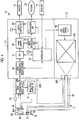
- an endoscope system 10 comprises an endoscope 11, a processor device 12, and a light source device 13.
- the endoscope 11 picks up the image of an object to be observed, which is present in an object to be examined, and outputs image pickup signals to the processor device 12.
- the processor device 12 generates the image of the object to be observed on the basis of the image pickup signals output from the endoscope 11, and outputs the generated image to the monitor 14.
- the light source device 13 supplies illumination light, with which the object to be observed is to be illuminated, to the endoscope 11.
- An input unit 15 such as a keyboard and a mouse, is connected to the processor device 12 in addition to the monitor 14.
- the input unit 15 is operated by an operator in a case where information about the object to be examined is to be input, and the like.
- the endoscope 11 comprises an insertion part 16 that is to be inserted into an object to be examined, an operation part 17 that is provided on the proximal end side of the insertion part 16 and is to be operated by an operator, and a universal cord 18 that extends from the lower end of the operation part 17.
- the insertion part 16 includes a distal end part 19, a bendable part 20, and a flexible tube part 21; and the distal end part 19, the bendable part 20, and the flexible tube part 21 are connected in this order from the distal end side.
- the bendable part 20 is formed of a plurality of connected bendable pieces, and is bendable in a vertical direction and a lateral direction. The upward bending of the bendable part is shown in Fig. 1 by a broken line.
- the flexible tube part 21 has flexibility that allows the flexible tube part 21 to be inserted into a convoluted tubular organ, such as the esophagus or the intestine.
- a communication cable that transmits reference clock signals used to drive an image pickup element 46 (see Fig. 4 ) and image pickup signals output from the image pickup element 46, a light guide 45 (see Fig. 4 ) that guides illumination light supplied from the light source device 13 to illumination windows 31 (see Fig. 2 ), and the like are inserted into the insertion part 16.
- the operation part 17 is provided with an angle knob 22, a release button 23, an air/water supply button 24, a forceps port 25, and the like.
- the angle knob 22 is rotationally operated in a case where an operator is to bend the bendable part 20 in the vertical direction or the lateral direction to make the distal end part 19 face in a desired direction.
- the release button 23 is operated to be pressed in a case where the image (static image) of the object to be observed is to be recorded.
- the air/water supply button 24 is operated in a case where air and water are supplied from an air/water supply nozzle 32 (see Fig. 2 ).
- Various treatment tools such as an electric scalpel, are inserted into the forceps port 25.
- the operation part 17 is provided with a mode changeover switch that is operated in a case where two observation modes of a normal observation mode and a special observation mode to be described later are to be switched, a zoom operation button that is used to move a zoom lens of an objective optical system 50 (see Fig. 4 ) along an optical axis to perform optical zoom, and the like, in addition to these.
- a connector 26 is provided at one end of the universal cord 18 that faces the processor device 12 and the light source device 13 provided on the side opposite to the operation part 17.
- the connector 26 is a composite connector that includes a connector 26A for communication and a connector 26B for a light source.
- the connector 26A for communication is attachably and detachably connected to the processor device 12, and the connector 26B for a light source is attachably and detachably connected to the light source device 13.
- the distal end face of the distal end part 19, which faces the object to be observed is provided with an observation window 30 that is positioned in the middle on the upper side, a pair of illumination windows 31 that is provided at positions on both sides of the observation window 30, an air/water supply nozzle 32 of which the opening faces the observation window 30, and a forceps outlet 33.
- the object to be observed is irradiated with illumination light, which is supplied from the light source device 13, through the illumination windows 31.
- the image of the object to be observed, which is irradiated with the illumination light is taken from the observation window 30. Air and water are ejected to the observation window 30 from the opening of the air/water supply nozzle 32, so that the observation window 30 is cleaned.
- the distal ends of various treatment tools inserted into the forceps port 25 protrude from the forceps outlet 33.
- a plurality of endoscope systems 10, such as endoscope systems 10A, 10B, ... are installed in a medical facility.
- each of the endoscope systems 10A, 10B, ... is provided in each of a plurality of endoscopy rooms of a medical facility.
- the respective processor devices 12A, 12B, ... and the respective light source devices 13A, 13B, ... of the respective endoscope systems 10A, 10B, ... are shared by the endoscopes 11A, 11B, ... of the respective endoscope systems 10A, 10B, .... That is, the endoscope 11A of the endoscope system 10A may be used while being connected to the processor device 12B and the light source device 13B of the endoscope system 10B.
- the respective processor devices 12A, 12B, ... are connected to a network 35, such as a local area network (LAN), built in the medical facility.
- a network 35 such as a local area network (LAN), built in the medical facility.
- An image storage server 36 and an image display device 37 are connected to the network 35.
- the respective processor devices 12A, 12B, ... transmit the static images of objects to be observed to the image storage server 36 through the network 35.
- the image storage server 36 is a server computer, and stores the static images transmitted from the respective processor devices 12A, 12B, ....
- the image storage server 36 searches for a desired static image according to a delivery request for a static image transmitted from the image display device 37, and delivers the searched static image to the image display device 37 through the network 35.
- the image display device 37 is a desktop personal computer, and is operated by a medical doctor of a diagnosis and treatment department having given an order for endoscopy.
- the image display device 37 includes a display 38 and an input unit 39, such as a keyboard and a mouse.
- the display 38 corresponds to a display unit, and displays the static image delivered from the image storage server 36.
- the input unit 39 is operated in a case where the delivery of a static image is to be requested.
- a plurality of image storage servers and a plurality of image display devices may be installed as with the endoscope systems 10A, 10B, ....
- alphabets such as A and B, used to distinguish the respective endoscope systems and the respective processor devices will be omitted below.
- the endoscope 11 comprises a light guide 45, an image pickup element 46, an image pickup control unit 47, and a signal transmission/reception unit 48.
- the light guide 45 is formed of a bundle of a plurality of optical fibers, and guides illumination light, which is supplied from the light source device 13, to the illumination windows 31.
- an incident end of the light guide 45 disposed in the connector 26B for a light source faces a light source unit 65 of the light source device 13.
- an emission end of the light guide 45 positioned at the distal end part 19 branches into two emission ends on the near side of the illumination windows 31 so that illumination light is guided to the pair of illumination windows 31.
- Irradiation lenses 49 are disposed at the back of the illumination windows 31.
- the emission ends of the light guide 45 are disposed at positions that face the irradiation lenses 49.
- Illumination light supplied from the light source device 13 is guided to the irradiation lenses 49 by the light guide 45, and the object to be observed is irradiated with the illumination light from the illumination windows 31.
- the irradiation lens 49 is formed of a concave lens, and increases the divergence angle of light to be emitted from the light guide 45. Accordingly, the wide range of the object to be observed can be irradiated with illumination light.
- the objective optical system 50 and the image pickup element 46 are disposed at the back of the observation window 30.
- the image of the object to be observed is incident on the objective optical system 50 through the observation window 30, and is formed on an image pickup surface 46A of the image pickup element 46 by the objective optical system 50.
- the image pickup element 46 is, for example, a charge coupled device (CCD) type image pickup element.
- a plurality of photoelectric conversion elements, such as photodiodes, which form pixels, are arrayed on the image pickup surface 46A of the image pickup element 46 in the form of a matrix.
- the photoelectric conversion element of each pixel photoelectrically converts received light, and stores a signal charge corresponding to the amount of received light thereof.
- the signal charge is converted into a voltage signal by an amplifier, and is read out.
- the voltage signal is subjected to noise removal, analog/digital conversion, and the like, and is input to the signal transmission/reception unit 48 as a digital image pickup signal.
- the image pickup control unit 47 controls the drive of the image pickup element 46. Specifically, the image pickup control unit 47 inputs driving signals to the image pickup element 46 in synchronization with reference clock signals that are input from a control unit 55 of the processor device 12 through the signal transmission/reception unit 48. The image pickup element 46 sequentially outputs image pickup signals at a predetermined frame rate, for example, 60 frames/sec on the basis of the driving signals input from the image pickup control unit 47.
- the signal transmission/reception unit 48 is provided in the connector 26A for communication.
- the signal transmission/reception unit 48 transmits and receives various signals to and from the processor device 12 by an optical transmission system that uses, for example, infrared light.
- the various signals also include a recording instruction signal for a static image generated by the operation of the release button 23, an operation signal (mode switching signal) of the mode changeover switch, an operation signal (zoom operation signal) of the zoom operation button, or the like in addition to the reference clock signals and the image pickup signals having been described above.
- the connector 26A for communication is provided with, for example, a power receiving unit, which receives power to be transmitted from the processor device 12 by a wireless power transmission system using magnetic-field resonance, in addition to the signal transmission/reception unit 48.
- the processor device 12 comprises a control unit 55, a signal transmission/reception unit 56, a digital signal processor (DSP) 57, a frame memory 58, an image processing unit 59, a display control unit 60, and a transmission unit 61.
- the control unit 55 includes a central processing unit (CPU), a read only memory (ROM) that stores a control program and setting data required for control, a random access memory (RAM) that loads a program and functions as a working memory, and the like; and controls the respective parts of the processor device 12 in a case where the CPU executes the control program.
- CPU central processing unit
- ROM read only memory
- RAM random access memory
- the signal transmission/reception unit 56 is the same as the signal transmission/reception unit 48 of the endoscope 11, and transmits and receives various signals to and from the endoscope 11 by an optical transmission system.
- the signal transmission/reception unit 56 transmits the reference clock signals, which are input from the control unit 55, to the signal transmission/reception unit 48. Further, the signal transmission/reception unit 56 receives the image pickup signals, which are output from the image pickup element 46, and the recording instruction signal, which is generated from the release button 23, from the signal transmission/reception unit 48; and outputs the image pickup signals to the DSP 57 and outputs the recording instruction signal to the control unit 55.
- the signal transmission/reception unit 56 also outputs the mode switching signal, the zoom operation signal, and the like to the control unit 55.
- the DSP 57 performs well-known processing, such as pixel interpolation, gradation conversion, gamma correction, and white balance correction, on the image pickup signals.
- the DSP 57 outputs the image pickup signals, which have been subjected to the processing, to the frame memory 58.
- the DSP 57 calculates exposure values on the basis of the image pickup signals. Then, the DSP 57 outputs the calculated exposure values to the control unit 55.
- the control unit 55 transmits exposure control signals, which correspond to the exposure values, to a light source control unit 66 of the light source device 13.
- the DSP 57 performs the calculation and output of the exposure values at a predetermined sampling cycle that is equal to or longer than a frame rate.
- the frame memory 58 stores image pickup signals that are output from the DSP 57 and image pickup signals that have been subjected to various kinds of image processing performed by the image processing unit 59.
- the display control unit 60 reads out the image pickup signals, which have been subjected to the image processing, from the frame memory 58; converts the image pickup signals into video signals, such as composite signals or component signals; and outputs the video signals to the monitor 14 as the image of the object to be observed.
- the image processing unit 59 performs various kinds of image processing, such as color emphasis processing and structure emphasis processing, on the image pickup signals, which are subjected to processing by the DSP 57 and are output to the frame memory 58, and generates the image of the object to be observed.
- the image processing unit 59 generates an image whenever the image pickup signals stored in the frame memory 58 are updated.
- the images, which are generated by the image processing unit 59, are sequentially output to the monitor 14 through the display control unit 60 as a video.
- the transmission unit 61 transmits the static image of the object to be observed to the outside through the network 35.
- the control unit 55 temporarily stops the rewriting of the image pickup signals in the frame memory 58 that is performed by the DSP 57.
- the transmission unit 61 reads out the image pickup signals (having been subjected to image processing), of which the rewriting is temporarily stopped, from the frame memory 58, and transmits the image pickup signals to the image storage server 36 through the network 35 as the static image of the object to be observed. Time in which the rewriting of the image pickup signals is temporarily stopped is, for example, 1 to 3 seconds.
- the light source device 13 comprises a light source unit 65 and a light source control unit 66.
- the light source unit 65 will be described in detail later with reference to Fig. 5 , but includes four different kinds of LEDs 70, 71, 72, and 73 corresponding to a light source.
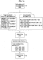
- the light source control unit 66 receives the exposure control signals transmitted from the control unit 55. Specifically, the exposure control signals are the amounts IR, IG, IB, and IV of driving current (see Fig. 16 ) of the respective LEDs 70 to 73.
- the amounts IR to IV of current are values that allow the amounts of light of the respective LEDs 70 to 73 to have predetermined intensities and ratios suitable for the observation of the object to be observed.
- the light source control unit 66 continuously gives the amounts IR to IV of current, which are represented by the received exposure control signals, to the respective LEDs 70 to 73 to turn on the respective LEDs 70 to 73.
- the amounts IR to IV of current may be given in the form of a pulse without being continuously given to perform pulse amplitude modulation (PAM) control for changing the amplitude of a pulse or pulse width modulation (PWM) control for changing the duty ratio of a pulse.
- PAM pulse amplitude modulation
- PWM pulse width modulation
- the light source unit 65 includes the respective color LEDs 70 to 73 having a red, a green, a blue, and a violet and a light source optical system 74.
- the red LED 70 emits light in a red wavelength range (red light RL, see Fig. 6 )
- the green LED 71 emits light in a green wavelength range (green light GL, see Fig. 7 )
- the blue LED 72 emits light in a blue wavelength range (blue light BL, see Fig. 8 )
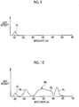
- the violet LED 73 emits light in a violet wavelength range (violet light VL, see Fig. 9 ).
- the respective LEDs 70 to 73 is an LED in which a P-type semiconductor and an N-type semiconductor are joined to each other as well known. Further, in a case where a voltage is applied, electrons and holes are recombined with each other beyond a bandgap near a PN junction and current flows. Energy corresponding to a bandgap is emitted as light at the time of the recombination. The amounts of light to be emitted from the respective LEDs 70 to 73 are increased or decreased according to the increase or decrease of power to be supplied (here, the amounts IR to IV of current).
- the wavelength of light to be emitted from each of the LEDs 70 to 73 is changed according to a temperature change.
- the peak wavelength of light to be emitted is shifted to a long wavelength side due to a temperature rise.
- the temperature changes of the respective LEDs 70 to 73 are caused by the increase or decrease of power to be supplied to the respective LEDs 70 to 73. That is, the wavelengths of lights to be emitted from the respective LEDs 70 to 73 are changed according to power to be supplied to the respective LEDs 70 to 73.
- the light source optical system 74 combines the optical paths of the respective color lights of a red light RL, a green light GL, a blue light BL, and a violet light VL into one optical path, and condenses the respective color lights on the incident end of the light guide 45 of the endoscope 11.
- the light source optical system 74 includes: collimating lenses 75, 76, 77, and 78 that guide the respective color lights to the incident end of the light guide 45, respectively; dichroic mirrors 79, 80, and 81 that combine the optical paths of the respective color lights transmitted through the respective collimating lenses 75 to 78; and a condenser lens 82 that condenses the respective color lights on the incident end of the light guide 45.
- the collimating lenses 75 to 78 transmit the respective color lights and change the respective color lights into lights substantially parallel to each other.
- Each of the dichroic mirrors 79 to 81 is an optical member where a dichroic filter having predetermined light transmission characteristics is formed on a transparent glass plate.
- the green LED 71 is disposed at a position where the optical axis of the green LED 71 coincides with the optical axis of the light guide 45. Further, the red LED 70 and the green LED 71 are disposed so that the optical axes of the red LED 70 and the green LED 71 are orthogonal to each other.
- the dichroic mirror 79 is provided at a position where the optical axes of the red LED 70 and the green LED 71 are orthogonal to each other.
- the blue LED 72 is also disposed so that the optical axis of the blue LED 72 is orthogonal to the optical axis of the green LED 71, and the dichroic mirror 80 is provided at a position where the optical axes of the blue LED 72 and the green LED 71 are orthogonal to each other.
- the blue LED 72 and the violet LED 73 are disposed so that the optical axes of the blue LED 72 and the violet LED 73 are orthogonal to each other, and the dichroic mirror 81 is provided at a position where the optical axes of the blue LED 72 and the violet LED 73 are orthogonal to each other.
- the dichroic mirror 79 is disposed at an attitude where the dichroic mirror 79 is inclined with respect to the optical axis of the red LED 70 and the optical axis of the green LED 71 by an angle of 45°.
- the dichroic mirror 80 is disposed at an attitude where the dichroic mirror 80 is inclined with respect to the optical axis of the green LED 71 and the optical axis of the blue LED 72 by an angle of 45°.
- the dichroic mirror 81 is disposed at an attitude where the dichroic mirror 80 is inclined with respect to the optical axis of the blue LED 72 and the optical axis of the violet LED 73 by an angle of 45°.
- the dichroic filter of the dichroic mirror 79 has, for example, characteristics that allow light in a red wavelength range having a wavelength of about 600 nm or more to be reflected and allow light in a blue wavelength range and a green wavelength range having a wavelength less than about 600 nm to be transmitted. For this reason, the dichroic mirror 79 reflects the red light RL emitted from the red LED 70 toward the condenser lens 82, and transmits the green light GL emitted from the green LED 71 toward the condenser lens 82. The optical paths of the green light GL and the red light RL are combined with each other by the action of the dichroic mirror 79.
- the dichroic filter of the dichroic mirror 80 has, for example, characteristics that allow light in a blue wavelength range having a wavelength less than about 480 nm to be reflected and allow light in a green wavelength range and a red wavelength range having a wavelength of about 480 nm or more to be transmitted. For this reason, the dichroic mirror 80 transmits the green light GL, which is transmitted through the dichroic mirror 79, and the red light RL, which is reflected by the dichroic mirror 79, toward the condenser lens 82. Further, the dichroic mirror 80 reflects the blue light BL emitted from the blue LED 72 toward the condenser lens 82.
- the dichroic filter of the dichroic mirror 81 has, for example, characteristics that allow light in a violet wavelength range having a wavelength less than about 430 nm to be reflected and allow light in a blue wavelength range, a green wavelength range, and a red wavelength range having a wavelength of 430 nm or more to be transmitted. For this reason, the dichroic mirror 81 transmits the blue light BL emitted from the blue LED 72 toward the condenser lens 82, and reflects the violet light VL emitted from the violet LED 73 toward the condenser lens 82. The optical paths of the blue light BL and the violet light VL are combined with each other by the action of the dichroic mirror 81.
- the dichroic mirror 80 Since the dichroic mirror 80 has characteristics that allow light in a blue wavelength range having a wavelength less than about 480 nm to be reflected as described above, the violet light VL reflected by the dichroic mirror 81 is reflected toward the condenser lens 82 by the dichroic mirror 80. Accordingly, the optical paths of all of the red light RL, the green light GL, the blue light BL, and the violet light VL are combined.
- the red LED 70 emits the red light RL, for example, including a wavelength component near the wavelength range of 600 nm to 650 nm that is a red wavelength range and having a central wavelength of 625 ⁇ 10 nm and a half-width of 20 ⁇ 10 nm.
- the green LED 71 emits the green light GL, for example, including a wavelength component near the wavelength range of 480 nm to 600 nm that is a green wavelength range and having a central wavelength of 550 ⁇ 10 nm and a half-width of 100 ⁇ 10 nm.
- the blue LED 72 emits the blue light BL, for example, including a wavelength component near the wavelength range of 420 nm to 500 nm that is a blue wavelength range and having a central wavelength of 460 ⁇ 10 nm and a half-width of 25 ⁇ 10 nm.
- the violet LED 73 emits the violet light VL, for example, including a wavelength component near the wavelength range of 380 nm to 420 nm that is a violet wavelength range and having a central wavelength of 405 ⁇ 10 nm and a half-width of 20 ⁇ 10 nm.
- a central wavelength means a wavelength corresponding to the center of the width of the spectral characteristics (also referred to as a light emission spectrum) of each color light, and a half-width is the range of a wavelength that represents the half of the peak of the spectral characteristics of each color light.
- Fig. 10 shows the spectral characteristics of mixed light ML of the red light RL, the green light GL, the blue light BL, and the violet light VL of which the optical paths are combined by the light source optical system 74.
- the mixed light ML is used as illumination light with which the object to be observed is to be illuminated.
- the mixed light ML is formed so that a wavelength range where a light intensity component is not present is not formed.
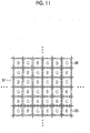
- color filters having the respective colors of a red, a green, and a blue are provided on the image pickup surface 46A of the image pickup element 46.
- These color filters 85 to 87 form so-called Bayer array, and the green filters 86 are arranged on every other pixel in a checker pattern and the red filters 85 and the blue filters 87 are arranged on the other pixels in a square lattice pattern.
- the pixel to which the red filter 85 is assigned will be referred to as an R pixel
- the pixel to which the green filter 86 is assigned will be referred to as a G pixel
- the pixel to which the blue filter 87 is assigned will be referred to as a B pixel.
- Fig. 12 shows the spectral characteristics (referred to as spectral transmission characteristics) of the respective color filters 85 to 87.
- the R pixel to which the red filter 85 is assigned responds to light in a wavelength range of about 580 nm to 800 nm and the G pixel to which the green filter 86 is assigned responds to light in a wavelength range of about 450 nm to 630 nm.
- the B pixel to which the blue filter 87 is assigned responds to light in a wavelength range of about 380 nm to 560 nm.
- reflected light corresponding to the red light RL is mainly received by the R pixels
- reflected light corresponding to the green light GL is mainly received by the G pixels
- reflected light corresponding to the blue light BL and the violet light VL is mainly received by the B pixels.
- the image pickup element 46 performs a storage operation for storing signal charges in pixels and a read-out operation for reading out the stored signal charges, during periods in which image pickup signals of one frame are acquired.
- the respective LEDs 70 to 73 are turned on in accordance with the timing of the storage operation of the image pickup element 46. Accordingly, the object to be observed is irradiated with the mixed light ML (RL+GL+BL+VL) as illumination light and the reflected light of the mixed light ML is incident on the image pickup element 46.
- the image pickup element 46 performs the color separation of the reflected light of the mixed light ML by the respective color filters 85 to 87.
- the image pickup element 46 sequentially outputs the image pickup signals of one frame according to a frame rate in accordance with a timing when the signal charges are read out.
- All the respective LEDs 70 to 73 are turned on regardless of each of the normal observation mode and the special observation mode.
- a ratio of the amount of the green light GL having relatively high spectral luminous efficiency is set high in the normal observation mode for the observation of overall properties of the object to be observed. Accordingly, since the object to be observed is irradiated with pseudo white light of which the amount is sufficient in the normal observation mode, a bright image can be obtained.
- a ratio of the amount of the violet light VL, of which the absorption coefficient in a superficial blood vessel is high is set high in the special observation mode for the emphasis and observation of the superficial blood vessel of the object to be observed.
- a ratio of the amount of the green light GL of which the absorption coefficient in an intermediate blood vessel obstructive to the observation of the superficial blood vessel is high, is set low. Accordingly, an image in which the structure of the superficial blood vessel closely related to a lesion, such as a tumor, is emphasized can be obtained in the special observation mode. Furthermore, a ratio of the amount of the green light GL may be set high as with that of the violet light VL in the special observation mode to obtain an image in which the visualization and brightness of the structure of the superficial blood vessel are compatible with each other.
- the transmission unit 61 comprises an image acquisition unit 90, an information acquisition unit 91, a creation unit 92, an embedding unit 93, and an output unit 94.
- the image acquisition unit 90 reads out the image pickup signals, of which the rewriting is temporarily stopped by a recording instruction signal and which have been subjected to image processing, from the frame memory 58. That is, the image acquisition unit 90 acquires the static image of the object to be observed that is picked up according to an operator's instruction for operation. The image acquisition unit 90 outputs the acquired static image to the embedding unit 93.
- the information acquisition unit 91 acquires tone change-related information and conversion information from the control unit 55.
- the tone change-related information is information about a change in the tone of the static image.
- the tone change-related information is wavelength change-related information about a change in the wavelength of illumination light.
- the conversion information is information that is used to convert the tone change-related information into a correction profile for correcting a change in the tone of the static image.
- the information acquisition unit 91 outputs the acquired tone change-related information and the acquired conversion information to the creation unit 92.
- the creation unit 92 creates a correction profile corresponding to the tone change-related information and the conversion information that are output from the information acquisition unit 91.
- the correction profile is used to correct the tone of the static image to reference tone in a case where the tone of the static image deviates from the reference tone.
- the creation unit 92 outputs the created correction profile to the embedding unit 93.
- the embedding unit 93 embeds the correction profile, which is output from the creation unit 92, in the static image that is output from the image acquisition unit 90. Embedding the correction profile in the static image specifically refers to as recording the correction profile as the supplementary information of the static image in association with the static image.
- the embedding unit 93 outputs the static image, in which the correction profile is embedded, to the output unit 94.
- the output unit 94 outputs the static image, in which the correction profile output from the embedding unit 93 is embedded, to a designated external transmission destination.
- the external transmission destination is specifically the image storage server 36 that is connected through the network 35.
- the image storage server 36 which is the transmission destination, is designated in advance through the input unit 15 by an operator.
- the control unit 55 outputs the tone change-related information and the conversion information to the information acquisition unit 91 in a case where a recording instruction signal is input to the control unit 55 from the signal transmission/reception unit 56.
- the control unit 55 does not output the tone change-related information and the conversion information to the information acquisition unit 91 in a case where a recording instruction signal is not input to the control unit 55 from the signal transmission/reception unit 56. That is, the tone change-related information is acquired by the information acquisition unit 91 only in a case where an operator gives an instruction for operation.
- a correction profile is not created naturally by the creation unit 92. That is, a correction profile is not created in a case where an instruction for operation is not given, and is created only in a case where an instruction for operation is given.
- the tone change-related information of this embodiment is the amounts IR to IV of current of the respective LEDs 70 to 73. Since the wavelengths of lights emitted from the respective LEDs 70 to 73 are changed according to the amounts IR to IV of current as described above, the amounts IR to IV of current correspond to the wavelength change-related information.
- the amounts IR to IV of current are represented by exposure control signals.
- the control unit 55 outputs the amounts IR to IV of current, which are represented by exposure control signals lately output to the light source control unit 66, to the information acquisition unit 91 as the tone change-related information in a case where a recording instruction signal is input to the control unit 55 from the signal transmission/reception unit 56.
- the conversion information is a red conversion function F(IR), a green conversion function F(IG), and a blue conversion function F(IB, IV).
- the red conversion function F(IR) is a function for obtaining matrix coefficients CR1, CR2, and CR3;
- the green conversion function F(IG) is a function for obtaining matrix coefficients CG1, CG2, and CG3;
- the blue conversion function F(IB, IV) is a function for obtaining matrix coefficients CB1, CB2, and CB3.
- the red conversion function F(IR) has the amount IR of current of the red LED 70 as a variable
- the green conversion function F(IG) has the amount IG of current of the green LED 71 as a variable
- the blue conversion function F(IB, IV) has the amount IB of current of the blue LED 72 and the amount IV of current of the violet LED 73 as variables.
- the creation unit 92 creates a tone correction matrix C1 by substituting each of the amounts of current of the tone change-related information into each conversion function of the conversion information and making a calculation. More specifically, the red matrix coefficients CR1 to CR3 are obtained from the red conversion function F(IR), the green matrix coefficients CG1 to CG3 are obtained from the green conversion function F(IG), and the blue matrix coefficients CB1 to CB3 are obtained from the blue conversion function F(IB, IV). Then, a matrix of 3 ⁇ 3 in which these matrix coefficients CR1 to CR3, CG1 to CG3, and CB1 to CB3 are arranged is created as the tone correction matrix C1.
- the tone correction matrix C1 can be embedded in a standard color profile, for example, an international color consortium (ICC) profile.
- the creation unit 92 outputs the created tone correction matrix C1 to the embedding unit 93 as the correction profile.
- ICC international color consortium
- the respective conversion functions of the conversion information are stored in a storage unit (for example, an ROM 134 or the like shown in Fig. 22 ) of the light source device 13 in advance.
- a storage unit for example, an ROM 134 or the like shown in Fig. 22
- the respective conversion functions are transmitted to the processor device 12 from the light source device 13 and are written in, for example, an ROM (not shown) of the control unit 55.
- the wavelength change-related information is not limited to the amounts IR to IV of current of the respective LEDs 70 to 73 and may be the peak wavelengths of the respective color lights or may be the amounts of shift of the peak wavelengths of the respective color lights from a reference peak wavelength. Alternatively, the amounts of the respective color lights may be used as the wavelength change-related information.
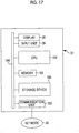
- the computer forming the image display device 37 comprises a storage device 100, a memory 101, a CPU 102, and a communication unit 103 in addition to the display 38 and the input unit 39 having been described above. These components are connected to each other through a data bus 104.
- the storage device 100 is a hard disk drive, which is built in the computer forming the image display device 37 or is connected the computer through a cable or a network, or a disk array in which a plurality of hard disk drives are arranged.
- a control program such as an operating system, various application programs (hereinafter, abbreviated as APs), various data appendant to these programs, and the like are stored in the storage device 100.
- the memory 101 is a work memory that is used in a case where the CPU 102 performs processing.
- the CPU 102 loads the programs, which are stored in the storage device 100, into the memory 101 and generally controls the respective parts of the computer by performing processing according to the programs.
- the communication unit 103 is a network interface that controls the transmission of various kinds of information to/from the image storage server 36 and the like through the network 35.
- the communication unit 103 transmits a delivery request for a static image to the image storage server 36, and receives a static image from the image storage server 36.
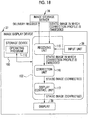
- an operating program 110 is stored in the storage device 100 of the image display device 37 as an AP.
- the operating program 110 is an AP that causes the computer to function as the image display device 37.
- the CPU 102 of the image display device 37 functions as a receiving unit 115, a correction unit 116, and a display control unit 117 in cooperation with the memory 101 and the like.
- the receiving unit 115 issues a delivery request for a static image including search keys (the order identification data (ID) of endoscopy, a patient name, a patient name ID, an endoscopy date, an operator name, and the like), which are input from the input unit 39, to the image storage server 36. Further, the receiving unit 115 has a reception function to receive a static image that is transmitted from the image storage server 36 according to a delivery request.
- This static image is a static image in which the correction profile is embedded by the embedding unit 93 of the transmission unit 61 of the processor device 12.
- the receiving unit 115 outputs the received static image to the correction unit 116.
- the correction unit 116 has a correction function to correct the static image by using the correction profile that is embedded in the static image. Specifically, in a case where an uncorrected static image is denoted by BI, the correction unit 116 multiplies the tone correction matrix C1 and the static image BI together to calculate a corrected static image AI1 as shown in Equation (1).
- AI 1 C 1 ⁇ BI
- Equation (1) is rewritten as Equation (2).
- AIR 1 AIG 1 AIB 1 CR 1 CR 2 CR 3 CG 1 CG 2 CG 3 CB 1 CB 2 CB 3 BIR BIG BIB
- the matrix coefficients CR1 to CR3, CG1 to CG3, and CB1 to CB3 are multiplied by the image pickup signals BIR, BIG, and BIB corresponding to the respective colors of a red, a green, and a blue, respectively.
- the correction unit 116 outputs the corrected static image AI1 to the display control unit 117.
- the display control unit 117 has a display control function to control the display of the corrected static image AI1 on the display 38.
- the display control unit 117 has a function to arrange and display a plurality of static images on the display 38.
- Fig. 19 shows an example where two static images (ID: "EN005" and “EN008") obtained from single endoscopy performed for the same patient ("xxx" having ID of "P012345”) at the same date ("2017/06/05”) are arranged and displayed.
- the plurality of static images, which are arranged and displayed, are not limited to the example shown in Fig. 19 , and may be a plurality of static images that are obtained from a combination of the other endoscope 11 and the other light source device 13.
- the endoscope 11 is connected to the processor device 12 and the light source device 13 and power is supplied to the processor device 12 and the light source device 13 to start the endoscope system 10. Then, the insertion part 16 of the endoscope 11 is inserted into an object to be examined to start the observation of the inside of the object to be examined.
- the amounts IR to IV of current to be supplied to the respective LEDs 70 to 73 are set to the respective LEDs 70 to 73 from the light source control unit 66. Accordingly, the respective LEDs 70 to 73 start to be turned on. Further, the amounts of the respective color lights are controlled by the light source control unit 66 to maintain target spectral characteristics.
- the optical paths of the respective color lights RL to VL emitted from the respective LEDs 70 to 73 are combined by the light source optical system 74, so that the respective color lights RL to VL form the mixed light ML.
- the mixed light ML is guided to the illumination windows 31 by the light guide 45, and the object to be observed is irradiated with the mixed light ML as illumination light from the illumination windows 31.
- the reflected light of the mixed light ML which is reflected by the object to be observed, is incident on the image pickup element 46 from the observation window 30.
- the image pickup element 46 the reflected light is subjected to color separation by the color filters 85 to 87 having the respective colors.
- image pickup signals corresponding to the respective colors of a red, a green, and a blue are output from the image pickup element 46. These image pickup signals are output to the processor device 12 from the signal transmission/reception unit 48.
- the image pickup signals are received by the signal transmission/reception unit 56 and are output to the DSP 57.
- the image pickup signals are subjected to various kinds of processing. After that, the image pickup signals are written in the frame memory 58 by the DSP 57.
- exposure values are calculated on the basis of the image pickup signals.
- Exposure control signals corresponding to the exposure values are generated by the control unit 55 and are transmitted to the light source control unit 66.
- the respective LEDs 70 to 73 are driven by the amounts IR to IV of current that are represented by the exposure control signals. Accordingly, the amounts of the red light RL, the green light GL, the blue light BL, and the violet light VL, which are emitted from the respective LEDs 70 to 73 and form the mixed light ML serving as illumination light, can be kept at constant intensities and constant ratios suitable for observation.
- the image pickup signals of the frame memory 58 are read out and are subjected to various kinds of image processing by the image processing unit 59, the image pickup signals are output to the monitor 14 through the display control unit 60 as the image of the object to be observed.
- the display of the image is updated according to the frame rate of the image pickup element 46.
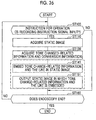
- the operator performs an operation for pressing the release button 23 to intend recording the static image of the object to be observed. Accordingly, a recording instruction signal is generated from the release button 23.
- the recording instruction signal is transmitted to the signal transmission/reception unit 56 from the signal transmission/reception unit 48, and is input to the control unit 55 from the signal transmission/reception unit 56.
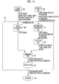
- Step ST110 image acquisition step
- the tone change-related information and the conversion information output from the control unit 55 are acquired by the information acquisition unit 91 as shown in Fig. 15A (Step ST120).
- the tone change-related information and the conversion information are output to the creation unit 92 from the information acquisition unit 91.
- a correction profile is created in the creation unit 92 according to the tone change-related information and the conversion information that are output from the information acquisition unit 91 (Step ST130).
- the correction profile is output to the embedding unit 93 from the creation unit 92.
- the correction profile output from the creation unit 92 is embedded in the static image output from the image acquisition unit 90 (Step ST140, embedding step).
- the static image in which the correction profile is embedded is output to the image storage server 36 by the output unit 94 (Step ST150, output step).
- a medical doctor of the diagnosis and treatment department starts the operating program 110 in the image display device 37 to observe the static image of endoscopy for which the medical doctor has given an order.
- the CPU 102 of the computer forming the image display device 37 functions as the receiving unit 115, the correction unit 116, and the display control unit 117 as shown in Fig. 18 .
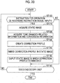
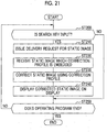
- Fig. 21 the medical doctor of the diagnosis and treatment department inputs the search keys for a desired static image through the input unit 39 of the image display device 37 (YES in Step ST200). Accordingly, a delivery request for a static image is issued to the image storage server 36 from the receiving unit 115 (Step ST210).
- a static image corresponding to the delivery request issued from the receiving unit 115 is searched in the image storage server 36. Then, the searched static image is transmitted to the image display device 37.
- the static image delivered from the image storage server 36 is received by the receiving unit 115 (Step ST220, receiving step).
- a correction profile is embedded in this static image.
- the static image is output to the correction unit 116 from the receiving unit 115.
- the static image is corrected using the correction profile, which is embedded in the static image, by the correction unit 116 (Step ST230, correction step).
- the tone of the static image is corrected by this correction.
- the corrected static image is output to the display control unit 117 from the correction unit 116, and is displayed on the display 38 by the display control unit 117 (Step ST240, display control step).
- the processor device 12 embeds the correction profile, which is created according to the tone change-related information about a change in the tone of the static image, in the static image by the embedding unit 93 and outputs the static image in which the correction profile is embedded to the image storage server 36 by the output unit 94. Accordingly, resources are not consumed in processing not having much necessity unlike in the case of the related art where a correction profile is created whenever image pickup signals are updated according to a frame rate and the correction profile is applied to the image pickup signals in real time during endoscopy where a change in the tone of the image does not much cause a problem. Therefore, it is possible to allow a change in the tone of an image not to be noticeable with less wasteful processing.
- the image display device 37 receives the static image in which the correction profile is embedded by the receiving unit 115, corrects the static image by using the correction profile by the correction unit 116, and displays the corrected static image on the display 38 by the display control unit 117, an image where a change in tone is not noticeable can be displayed.
- the tones of the plurality of static images are unified, efficiency can be improved in a case where the plurality of static images are arranged and displayed to be compared and examined. For example, since the tones of lesions appearing in two static images may be different from each other in the two static images in a case where the tones of the two static images are not unified, the images need to be observed in consideration of a difference in tone. On the other hand, in a case where the tones of the two static images are unified, the images do not need to be observed in consideration of a difference in the tone of the lesion between the respective static images.
- the tone change-related information is acquired only in a case where an instruction to perform an operation for recording a static image is given, and the correction profile is also created only in a case where an instruction for operation is given. Accordingly, there is no waste in processing.
- the wavelength change-related information about a change in the wavelength of illumination light is used as the tone change-related information, a change in the tone of the image caused by a change in the wavelength of illumination light, which is an unavoidable problem, can be reliably corrected in a case where a semiconductor light source is used.
- the correction profile includes the matrix coefficients CR1 to CR3, CG1 to CG3, and CB1 to CB3 (tone correction matrix C1) to be multiplied by the image pickup signals BIR, BIG, and BIB corresponding to the respective colors, respectively, as shown in Equation (2), the tone of the entire color gamut of the static image can be corrected.
- the tone correction matrix C1 can be embedded in, for example, a standard color profile, such as an ICC profile
- the static image can be corrected with general-purpose processing corresponding to a standard color profile in the correction unit 116 of the image display device 37. For this reason, the operating program 110 serving as the base of the correction unit 116 can be relatively simply created.
- the wavelength change-related information has been exemplified as the tone change-related information in the first embodiment.
- the spectral characteristic information of the color filters 85 to 87 of the image pickup element 46 (hereinafter, referred to as image pickup element-spectral characteristic information) and the spectral characteristic information of illumination light (hereinafter, referred to as illumination light-spectral characteristic information) are used as the tone change-related information instead of the wavelength change-related information.
- the spectral characteristics of the color filters 85 to 87 are shown in Fig. 12 . Further, the spectral characteristics of illumination light are shown in Figs. 6 to 10 . There is a deviation between the respective endoscopes 11A, 11B, ... in terms of the spectral characteristics of the color filters 85 to 87. There is a deviation between the respective light source devices 13A, 13B, ... even in terms of the spectral characteristics of illumination light. The tone of the image is also changed due to a deviation in the spectral characteristics of the color filters 85 to 87 and illumination light.
- a transmission unit 130 of the second embodiment shown in Figs. 22 and 23 is provided with an information acquisition unit 131 that acquires the image pickup element-spectral characteristic information representing a deviation in the spectral characteristics of the color filters 85 to 87 and the illumination light-spectral characteristic information representing a deviation in the spectral characteristics of illumination light as the tone change-related information, and a creation unit 132 that creates a correction profile corresponding to the image pickup element-spectral characteristic information and the illumination light-spectral characteristic information.
- the image pickup element-spectral characteristic information can also be represented by the central wavelengths and peak wavelengths of the respective color filters 85 to 87 and the amounts of shift of half-widths of the respective color filters 85 to 87 from the reference of a half-width, and can also be represented as the relative spectral sensitivity values of the respective color filters 85 to 87 for every wavelength.
- the illumination light-spectral characteristic information can also be represented by the central wavelengths and peak wavelengths of the respective color lights and the amounts of shift of half-widths of the respective color lights from the reference of a half-width, and can also be represented as the relative spectral emissivities of the respective color lights for every wavelength.
- the image pickup element-spectral characteristic information is measured in advance and is stored in an ROM 133 of an endoscope 11 at the time of shipment of the endoscope 11.
- the illumination light-spectral characteristic information is measured in advance and is stored in an ROM 134 of a light source device 13 at the time of shipment of the light source device 13.
- Each of the ROMs 133 and 134 corresponds to a storage unit.
- the image pickup element-spectral characteristic information and the illumination light-spectral characteristic information are read out to a control unit 135 of a processor device from the respective ROMs 133 and 134 and are written in an ROM (not shown) of the control unit 135.
- the image pickup element-spectral characteristic information and the illumination light-spectral characteristic information are output to the information acquisition unit 131 from the control unit 135 as with the wavelength change-related information of the first embodiment only in a case where a recording instruction signal is input (in a case where an operator gives an instruction for operation).
- the information acquisition unit 131 acquires the image pickup element-spectral characteristic information and the illumination light-spectral characteristic information, which are output from the control unit 135 and serve as the tone change-related information, and conversion information.
- the information acquisition unit 131 outputs the acquired illumination light-spectral characteristic information, the acquired image pickup element-spectral characteristic information, and the acquired conversion information to the creation unit 132.
- the conversion information in this case may be, for example, a function that uses the central wavelengths and peak wavelengths of the respective color filters 85 to 87 and the amounts of shift of half-widths of the respective color filters 85 to 87 from the reference of a half-width of the image pickup element-spectral characteristic information and the central wavelengths and peak wavelengths of the respective color lights and the amounts of shift of half-widths of the respective color lights from the reference of a half-width of the illumination light-spectral characteristic information as variables; and may be the amount of correction that is obtained from the relative spectral sensitivity values and the relative spectral emissivities for every wavelength.
- the creation unit 132 obtains matrix coefficients CR#1, CR#2, CR#3, CG#1, CG#2, CG#3, CB#1, CB#2, and CB#3, which correspond to the respective colors of a red, a green, and a blue, on the basis of the image pickup element-spectral characteristic information, the illumination light-spectral characteristic information, and the conversion information output from the information acquisition unit 131, respectively; and creates a matrix of 3 ⁇ 3, in which these matrix coefficients are arranged as in the tone correction matrix C1 of the first embodiment, as a tone correction matrix C2.
- the tone correction matrix C2 can also be embedded in a standard color profile, such as an ICC profile, as with the tone correction matrix C1.
- the creation unit 132 outputs the created tone correction matrix C2 to the embedding unit 93 as the correction profile. Since subsequent processing is the same as that of the first embodiment, the description thereof will be omitted.
- the correction unit 116 of the CPU 102 of the image display device 37 multiplies the tone correction matrix C2 and the static image BI together to calculate a corrected static image AI2 as shown in Equation (3).
- AI 2 C 2 ⁇ BI
- Equation (3) is rewritten as Equation (4).
- AIR 2 AIG 2 AIB 2 CR # 1 CR # 2 CR # 3 CG # 1 CG # 2 CG # 3 CB # 1 CB # 2 CB # 3 BIR BIG BIB
- the matrix coefficients CR#1 to CR#3, CG#1 to CG#3, and CB#1 to CB#3 are also multiplied by the image pickup signals BIR, BIG, and BIB corresponding to the respective colors of a red, a green, and a blue, respectively.
- the static image AI2 Since the above-mentioned correction is performed on the static image BI, the static image AI2 of which a change in tone caused by a deviation in the spectral characteristics of the color filters 85 to 87 and the spectral characteristics of illumination light is corrected can be obtained.
- the image pickup element-spectral characteristic information and the illumination light-spectral characteristic information are measured in advance and are stored in the respective ROMs 133 and 134, labor for measuring these pieces of information every time can be saved and these pieces of information can be simply acquired by being just read out from the respective ROMs 133 and 134.
- the first embodiment where the wavelength change-related information is used as the tone change-related information and the second embodiment where the image pickup element-spectral characteristic information and the illumination light-spectral characteristic information are used as the tone change-related information may be performed compositely.
- the corrected static image AI12 is represented by Equation (5).
- AI 12 C 1 ⁇ C 2 ⁇ BI
- Equation (5) is rewritten as Equation (6).
- AIR 12 AIG 12 AIB 12 CR 1 CR 2 CR 3 CG 1 CG 2 CG 3 CB 1 CB 2 CB 3 CR # 1 CR # 2 CR # 3 CG # 1 CG # 2 CG # 3 CB # 1 CB # 2 CB # 3 BIR BIG BIB
- the first embodiment where the wavelength change-related information is used as the tone change-related information and the second embodiment where the image pickup element-spectral characteristic information and the illumination light-spectral characteristic information are used as the tone change-related information are performed compositely, there is no concern that a change in the tone of the image caused by a change in the wavelength of illumination light and a change in the tone of the image caused by a deviation in the spectral characteristics of the color filters 85 to 87 and the spectral characteristics of illumination light may be recognized.
- a correction profile has been embedded in the static image in the respective embodiments having been described above, but the tone change-related information is embedded in the static image in a third embodiment shown in Figs. 24 to 27 .
- a transmission unit 140 of the third embodiment is mainly different from the transmission unit 61 of the first embodiment in that the transmission unit 140 is not provided with the creation unit 92.
- the information acquisition unit 91 outputs the tone change-related information and the conversion information to the embedding unit 141.
- the embedding unit 141 embeds the tone change-related information and the conversion information, which are output from the information acquisition unit 91, in the static image, which is output from the image acquisition unit 90, instead of the correction profile of the first embodiment.
- the embedding unit 141 outputs the static image, in which the tone change-related information and the like are embedded, to an output unit 142.
- the output unit 142 outputs the static image, in which the tone change-related information and the like are embedded and which is received from the embedding unit 141, to the image storage server 36 through the network 35.
- an operating program 143 is stored in a storage device 100 of an image display device 37 of the third embodiment.
- a CPU 102 of the image display device 37 functions as the same creation unit 146 as the creation unit 92 of the first embodiment in addition to the same receiving unit 145 as the receiving unit 115 of the first embodiment, the correction unit 116, and the display control unit 117 in cooperation with the memory 101 and the like.
- the receiving unit 145 receives the static image in which the tone change-related information and the like are embedded by the embedding unit 141 of the transmission unit 140 and which is transmitted from the image storage server 36.
- the receiving unit 145 outputs the received static image to the creation unit 146.
- the creation unit 146 has a creation function to create a correction profile from the tone change-related information and the conversion information that are embedded in the static image.
- a method of creating the correction profile is the same as that of the creation unit 92 of the first embodiment.
- the creation unit 146 outputs the created correction profile to the correction unit 116. Since subsequent processing is the same as that of the first embodiment, the description thereof will be omitted.
- Figs. 26 and 27 The flow of the processing of the second embodiment is shown in Figs. 26 and 27 . Portions surrounded by a broken line in Figs. 26 and 27 are steps different from those of the first embodiment. The steps different from those of the first embodiment will be mainly described below.
- the tone change-related information and the like output from the information acquisition unit 91 are embedded in the static image output from the image acquisition unit 90 (Step ST141, embedding step).
- the static image in which the tone change-related information and the like are embedded is output to the image storage server 36 by the output unit 142 (Step ST151, output step).
- the static image in which the tone change-related information and the like are embedded and which is delivered from the image storage server 36, is received by the receiving unit 145 (Step ST221, receiving step).
- the static image is output to the creation unit 146 from the receiving unit 145.
- a correction profile is created in the creation unit 146 according to the tone change-related information and the conversion information that are embedded in the static image (Step ST131, creation step).
- the tone change-related information may be embedded in the static image by the embedding unit 141 instead of the correction profile and the static image in which the tone change-related information is embedded may be output to the image storage server 36 by the output unit 142.
- the creation unit 146 may be provided in the CPU 102 of the image display device 37 and a correction profile may be created in the image display device 37. Since the processor device does not need to be provided with a function to create a correction profile in this case, the configuration of the processor device can be simplified.
- the receiving unit of the CPU 102 of the image display device 37 may be adapted to receive both a static image in which a correction profile is embedded and a static image in which the tone change-related information is embedded.
- the creation unit 146 does not operate in a case where the static image in which the correction profile is embedded is received by the receiving unit, and the creation unit 146 operates to create a correction profile only in a case where the static image in which the tone change-related information is embedded is received by the receiving unit.
- the tone correction matrices C1 and C2 have been exemplified as the correction profile in the respective embodiments having been described above, but a white balance correction coefficient, a gradation conversion coefficient, a three-dimensional look-up table, and the like may be included in the correction profile in addition to the tone correction matrices C1 and C2.
- the color filter is not limited to a combination of primary colors of a red, a green, and a blue described in the respective embodiments having been described above, and may employ a combination of complementary colors of a cyan, a magenta, and a yellow.
- the light source is not limited to the LED described in the respective embodiments having been described above, and may be a laser diode (LD).
- the invention is effective even in a case where a xenon lamp or a metal halide lamp in the related art is used as the light source.
- the control unit may have the functions of the image acquisition unit, the creation unit, the embedding unit, and the output unit.
- a range covered by the image storage server 36 is not limited to one medical facility and may correspond to a plurality of medical facilities.
- a wide area network (WAN) is used as the network 35.
- the computer forming the image display device 37 is not limited to a desktop computer.
- the computer may be a laptop computer or a tablet computer.
- processing units for performing various kinds of processing in the respective embodiments having been described above such as the image acquisition unit 90, the information acquisition units 91 and 131, the creation units 92, 132, and 146, the embedding units 93 and 141, the output units 94 and 142, the receiving units 115 and 145, the correction unit 116, and the display control unit 117, is various processors to be described below.
- processors include a CPU, a programmable logic device (PLD), a dedicated electrical circuit, and the like.
- the CPU is a general-purpose processor that functions as various processing units by executing software (program) as well known.
- the PLD is a processor of which circuit configuration can be changed after manufacture, such as a field programmable gate array (FPGA).
- a dedicated electrical circuit is a processor having circuit configuration designed exclusively to perform specific processing, such as an application specific integrated circuit (ASIC).
- One processing unit may be formed of one of these various processors, and may be formed of a combination of two or more same kind or different kinds of processors (for example, a plurality of FPGAs or a combination of a CPU and an FPGA). Further, a plurality of processing units are formed of one processor. As an example where a plurality of processing units are formed of one processor, first, there is an aspect where one processor is formed of a combination of one or more CPUs and software and this processor functions as a plurality of processing units. Second, there is an aspect where a processor fulfilling the functions of the entire system including a plurality of processing units by one integrated circuit (IC) chip as typified by System On Chip (SoC) or the like is used. As described above, various processing units are formed using one or more of the above-mentioned various processors as hardware structure.
- IC integrated circuit
- SoC System On Chip
- a processor device according to additional claim 1, an endoscope system according to additional claim 2, and an image display device according to additional claim 3 to be described below can be grasped from the above description.
- a processor device to which an endoscope irradiating an object to be observed with illumination light supplied from a light source is to be connected comprising:
- An endoscope system comprising:
- An image display device comprising:
- the invention can also be applied to a fiberscope that guides the image of an object to be observed to an eyepiece part by an image guide, a processor device to which an ultrasonic endoscope including a distal end part in which an ultrasonic transducer is built in addition to an image pickup element is to be connected, and an endoscope system.
Landscapes
- Health & Medical Sciences (AREA)
- Life Sciences & Earth Sciences (AREA)
- Engineering & Computer Science (AREA)
- Surgery (AREA)
- Physics & Mathematics (AREA)
- Optics & Photonics (AREA)
- Heart & Thoracic Surgery (AREA)
- Animal Behavior & Ethology (AREA)
- Pathology (AREA)
- Radiology & Medical Imaging (AREA)
- Biophysics (AREA)
- Biomedical Technology (AREA)
- Veterinary Medicine (AREA)
- Medical Informatics (AREA)
- Molecular Biology (AREA)
- Nuclear Medicine, Radiotherapy & Molecular Imaging (AREA)
- General Health & Medical Sciences (AREA)
- Public Health (AREA)
- Signal Processing (AREA)
- Multimedia (AREA)
- Mechanical Engineering (AREA)
- Astronomy & Astrophysics (AREA)
- General Physics & Mathematics (AREA)
- Microelectronics & Electronic Packaging (AREA)
- Endoscopes (AREA)
- Instruments For Viewing The Inside Of Hollow Bodies (AREA)
Abstract
Description
- The present invention relates to a processor device, a method of operating the processor device, an endoscope system, an image display device, a method of operating the image display device, and an operating program for the image display device.
- Endoscopy for observing an object to be observed, such as the surface of the stomach or the large intestine of an object to be examined (patient), with an endoscope is performed in a medical field. An endoscope includes an insertion part that is to be inserted into an object to be examined and an operation part that is provided on the proximal end side of the insertion part and is to be operated by an operator, such as an endoscopy technician. The distal end of the insertion part is provided with an image pickup element that picks up the image of an object to be observed. The operation part is provided with a release button that is used to record the image (static image) of an object to be observed.
- The endoscope is connected to a light source device and a processor device, and the endoscope, the light source device, and the processor device form an endoscope system. A light source, which emits illumination light with which an object to be observed is to be illuminated, is built in the light source device. A semiconductor light source, for example, a light-emitting diode (hereinafter, abbreviated as an LED) is used as the light source. There is no semiconductor light source that has broad spectral characteristics covering the entire wavelength range of visible light, such as a xenon lamp or a metal halide lamp having been used as a light source in the related art. For this reason, a plurality of kinds of semiconductor light sources having different wavelength ranges, for example, three semiconductor light sources corresponding to a red, a green, and a blue are mounted on the light source device, which employs semiconductor light sources, to generate white light.
- The image pickup element of the endoscope comprises color filters having a plurality of colors, for example, the respective colors of a red, a green, and a blue, and sequentially outputs image pickup signals, which correspond to the respective colors, to the processor device at a predetermined frame rate. The processor device performs various kinds of processing on the image pickup signals that correspond to the respective colors and are output from the image pickup element. Further, the image pickup signals subjected to the processing are sequentially output to a monitor as the video of the object to be observed. An operator observes the video on the monitor, and operates the release button as necessary to record the static image.
- This kind of endoscope system has a problem that the tone of an image is changed in the related art. There are two causes of this problem. One of the two causes is a change in the wavelength of illumination light depending on the temperature of a semiconductor light source, such as an LED. In a case where the wavelength of illumination light is changed, the tone of the illumination light is also naturally changed and the tone of an image is eventually changed.
- The other of the two causes is the individual difference of the light source of each light source device and the image pickup element of each endoscope. Specifically, the other of the two causes is a deviation in the spectral characteristics of illumination light and a deviation in the spectral characteristics of the color filters of the image pickup element. For example, the spectral characteristics of a color filter of an endoscope A are XA but the spectral characteristics of a color filter of an endoscope B are XB.
- A case where the endoscope A is connected to a light source device of which the spectral characteristics of illumination light are Y and a case where the endoscope B is connected to a light source device of which the spectral characteristics of illumination light are Y are thought here. In the former case, an image has a tone corresponding to the spectral characteristics XA of the color filter of the endoscope A and the spectral characteristics Y of illumination light of the light source device. However, in the latter case, an image has a tone corresponding to the spectral characteristics XB of the color filter of the endoscope B and the spectral characteristics Y of illumination light of the light source device. That is, the tone of an image is changed between a case where the endoscope A is used and a case where the endoscope B is used.
-
JP2016-174921A JP2016-174921A JP2016-174921A - Further,
JP2016-174921A JP2016-174921A - Since a change in the wavelength of illumination light is not rapid, a change in the tone of an image, which is caused by a change in the wavelength of illumination light, is relatively gentle. For this reason, it is difficult for a change in the tone of an image to be recognized during endoscopy. Further, since an image cannot be compared with an image obtained from a combination of another endoscope having different spectral characteristics and the light source device during endoscopy, it is also difficult for a change in the tone of an image, which is caused by a deviation in the spectral characteristics of illumination light and a deviation in the spectral characteristics of the color filters of the image pickup element, to be recognized during endoscopy.
- On the other hand, it is easy for a change in the tone of an image to be recognized in a case where a static image is observed using an image display device after endoscopy. That is, this case corresponds to a case where a static image obtained before a change in the wavelength of illumination light is compared with a static image obtained after a change in the wavelength of illumination light and a case where an image is compared with an image obtained from a combination of an endoscope having different spectral characteristics and the light source device. As described above, a change in the tone of an image does not become a problem much during endoscopy and becomes a problem in a case where a static image is observed after endoscopy.
- However, in
JP2016-174921A JP2016-174921A - An object of the invention is to provide a processor device that can allow a change in the tone of an image not to be noticeable with less wasteful processing, a method of operating the processor device, and an endoscope system.
- Further, an object of the invention is to provide an image display device that can display an image where a change in tone is not noticeable, a method of operating the image display device, and an operating program for the image display device.
- To achieve the object, a processor device of the invention is a processor device to which an endoscope irradiating an object to be observed with illumination light supplied from a light source is to be connected, and comprises an image acquisition unit, an embedding unit, and an output unit. The image acquisition unit acquires a static image of the object to be observed picked up according to an operator's instruction for operation. The embedding unit embeds tone change-related information about a change in a tone of the static image or a correction profile, which is created according to the tone change-related information and is used to correct a change in the tone, in the static image. The output unit outputs the static image, in which the tone change-related information or the correction profile is embedded, to the outside.
- It is preferable that the tone change-related information is acquired only in a case where the instruction for operation is given. Further, it is preferable that the correction profile is created only in a case where the instruction for operation is given.
- It is preferable that the tone change-related information is wavelength change-related information about a change in a wavelength of the illumination light depending on a temperature of the light source.
- It is preferable that the tone change-related information is spectral characteristic information of the illumination light and spectral characteristic information of a color filter of an image pickup element picking up an image of the object to be observed.
- It is preferable that the spectral characteristic information of the illumination light and the spectral characteristic information of the color filter are measured in advance and are stored in a storage unit.
- It is preferable that the correction profile includes matrix coefficients to be multiplied by image pickup signals which correspond to a plurality of colors and are output from an image pickup element picking up an image of the object to be observed.
- It is preferable that the correction profile is embedded in a standard color profile.
- It is preferable that the light source is a light-emitting diode.
- A method of operating a processor device of the invention is a method of operating a processor device to which an endoscope irradiating an object to be observed with illumination light supplied from a light source is to be connected, and comprises an image acquisition step, an embedding step, and an output step. The image acquisition step acquires a static image of the object to be observed picked up according to an operator's instruction for operation. The embedding step embeds tone change-related information about a change in a tone of the static image or a correction profile, which is created according to the tone change-related information and is used to correct a change in the tone, in the static image. The output step outputs the static image, in which the tone change-related information or the correction profile is embedded, to the outside.
- An endoscope system of the invention comprises an endoscope that irradiates an object to be observed with illumination light supplied from a light source, a light source device in which the light source is built, and a processor device to which the endoscope and the light source device are to be connected. The processor device includes an image acquisition unit, an embedding unit, and an output unit. The image acquisition unit acquires a static image of the object to be observed picked up according to an operator's instruction for operation. The embedding unit embeds tone change-related information about a change in a tone of the static image or a correction profile, which is created according to the tone change-related information and is used to correct a change in the tone, in the static image. The output unit outputs the static image, in which the tone change-related information or the correction profile is embedded, to the outside.
- An image display device of the invention comprises a receiving unit, a creation unit, a correction unit, and a display control unit. The receiving unit receives a static image in which tone change-related information about a change in a tone of the static image or a correction profile created according to the tone change-related information and used to correct a change in the tone is embedded. The creation unit creates the correction profile from the tone change-related information in a case where the static image received by the receiving unit is the static image in which the tone change-related information is embedded. The correction unit performs the correction the static image by using the correction profile. The display control unit controls display of the static image, on which the correction has been, on a display unit.
- A method of operating an image display device of the invention comprises a receiving step, a creation step, a correction step, and a display control step. A static image in which tone change-related information about a change in a tone of the static image or a correction profile created according to the tone change-related information and used to correct a change in the tone is embedded is received in the receiving step. In the creation step, the correction profile is created from the tone change-related information in a case where the static image received in the receiving step is the static image in which the tone change-related information is embedded. In the correction step, the correction is performed on the static image by using the correction profile. Display of the static image, on which the correction has been performed, on a display unit is controlled in the display control step.
- An operating program for an image display device of the invention causes a computer to perform a reception function, a creation function, a correction function, and a display control function. The reception function receives a static image in which tone change-related information about a change in a tone of the static image or a correction profile created according to the tone change-related information and used to correct a change in the tone is embedded. The creation function creates the correction profile from the tone change-related information in a case where the static image received by the reception function is the static image in which the tone change-related information is embedded. The correction function performs the correction on the static image by using the correction profile. The display control function controls display of the static image, on which the correction has been performed, on a display unit.
- According to the invention, tone change-related information about a change in a tone of a static image or a correction profile, which is created according to the tone change-related information and is used to correct a change in the tone, is embedded in the static image and the static image is output to the outside. Accordingly, it is possible to provide a processor device that can allow a change in the tone of an image not to be noticeable with less wasteful processing, a method of operating the processor device, and an endoscope system.
- Further, according to the invention, a static image, in which tone change-related information about a change in a tone of a static image or a correction profile created according to the tone change-related information and used to correct a change in the tone is embedded, is received; correction is performed on the static image by using the correction profile; and the static image on which the correction has been performed is displayed on a display unit. Accordingly, it is possible to provide an image display device that can display an image where a change in tone is not noticeable, a method of operating the image display device, and an operating program for the image display device.
-
-
Fig. 1 is a diagram showing the appearance of an endoscope system. -
Fig. 2 is a front view of a distal end part of an endoscope. -
Fig. 3 is a diagram showing endoscope systems, an image storage server, and an image display device. -
Fig. 4 is a block diagram of the endoscope system. -
Fig. 5 is a diagram showing a light source unit. -
Fig. 6 is a graph showing the spectral characteristics of red light emitted from a red LED. -
Fig. 7 is a graph showing the spectral characteristics of green light emitted from a green LED. -
Fig. 8 is a graph showing the spectral characteristics of blue light emitted from a blue LED. -
Fig. 9 is a graph showing the spectral characteristics of violet light emitted from a violet LED. -
Fig. 10 is a graph showing the spectral characteristics of mixed light that is formed of red light, green light, blue light, and violet light. -
Fig. 11 is a diagram showing the array of color filters. -
Fig. 12 is a graph showing the spectral characteristics of the color filters. -
Fig. 13 is a diagram showing the irradiation timing of illumination light and the operation timing of an image pickup element. -
Fig. 14 is a block diagram of a transmission unit. -
Fig. 15A is a diagram showing an aspect where tone change-related information is acquired only in a case where an operator gives an instruction for operation, and shows an aspect where tone change-related information and conversion information are output to an information acquisition unit from a control unit in a case where a recording instruction signal is input. -
Fig. 15B is a diagram showing an aspect where tone change-related information is acquired only in a case where an operator gives an instruction for operation, and shows an aspect where tone change-related information and conversion information are not output to the information acquisition unit from the control unit in a case where a recording instruction signal is not input. -
Fig. 16 is a diagram showing an aspect where a correction profile according to tone change-related information and conversion information is created. -
Fig. 17 is a block diagram of a computer forming the image display device. -
Fig. 18 is a block diagram of a CPU of the computer forming the image display device. -
Fig. 19 is a diagram showing an aspect where a plurality of static images are arranged and displayed. -
Fig. 20 is a flowchart showing the procedure of processing of a processor device. -
Fig. 21 is a flowchart showing the procedure of processing of the image display device. -
Fig. 22 is a block diagram of a transmission unit of a second embodiment. -
Fig. 22 is a block diagram of the transmission unit of the second embodiment. -
Fig. 24 is a block diagram of a transmission unit of a third embodiment. -
Fig. 25 is a block diagram of a CPU of a computer forming an image display device of the third embodiment. -
Fig. 26 is a flowchart showing the procedure of processing of a processor device of the third embodiment. -
Fig. 27 is a flowchart showing the procedure of processing of the image display device of the third embodiment. - In
Fig. 1 , anendoscope system 10 comprises anendoscope 11, aprocessor device 12, and alight source device 13. Theendoscope 11 picks up the image of an object to be observed, which is present in an object to be examined, and outputs image pickup signals to theprocessor device 12. Theprocessor device 12 generates the image of the object to be observed on the basis of the image pickup signals output from theendoscope 11, and outputs the generated image to themonitor 14. Thelight source device 13 supplies illumination light, with which the object to be observed is to be illuminated, to theendoscope 11. - An
input unit 15, such as a keyboard and a mouse, is connected to theprocessor device 12 in addition to themonitor 14. Theinput unit 15 is operated by an operator in a case where information about the object to be examined is to be input, and the like. - The
endoscope 11 comprises aninsertion part 16 that is to be inserted into an object to be examined, anoperation part 17 that is provided on the proximal end side of theinsertion part 16 and is to be operated by an operator, and auniversal cord 18 that extends from the lower end of theoperation part 17. - The
insertion part 16 includes adistal end part 19, abendable part 20, and aflexible tube part 21; and thedistal end part 19, thebendable part 20, and theflexible tube part 21 are connected in this order from the distal end side. Thebendable part 20 is formed of a plurality of connected bendable pieces, and is bendable in a vertical direction and a lateral direction. The upward bending of the bendable part is shown inFig. 1 by a broken line. Theflexible tube part 21 has flexibility that allows theflexible tube part 21 to be inserted into a convoluted tubular organ, such as the esophagus or the intestine. - A communication cable that transmits reference clock signals used to drive an image pickup element 46 (see
Fig. 4 ) and image pickup signals output from theimage pickup element 46, a light guide 45 (seeFig. 4 ) that guides illumination light supplied from thelight source device 13 to illumination windows 31 (seeFig. 2 ), and the like are inserted into theinsertion part 16. - The
operation part 17 is provided with anangle knob 22, arelease button 23, an air/water supply button 24, a forceps port 25, and the like. Theangle knob 22 is rotationally operated in a case where an operator is to bend thebendable part 20 in the vertical direction or the lateral direction to make thedistal end part 19 face in a desired direction. Therelease button 23 is operated to be pressed in a case where the image (static image) of the object to be observed is to be recorded. The air/water supply button 24 is operated in a case where air and water are supplied from an air/water supply nozzle 32 (seeFig. 2 ). Various treatment tools, such as an electric scalpel, are inserted into the forceps port 25. Theoperation part 17 is provided with a mode changeover switch that is operated in a case where two observation modes of a normal observation mode and a special observation mode to be described later are to be switched, a zoom operation button that is used to move a zoom lens of an objective optical system 50 (seeFig. 4 ) along an optical axis to perform optical zoom, and the like, in addition to these. - The communication cable and the
light guide 45, which extend from theinsertion part 16, are inserted into theuniversal cord 18. Aconnector 26 is provided at one end of theuniversal cord 18 that faces theprocessor device 12 and thelight source device 13 provided on the side opposite to theoperation part 17. Theconnector 26 is a composite connector that includes aconnector 26A for communication and aconnector 26B for a light source. Theconnector 26A for communication is attachably and detachably connected to theprocessor device 12, and theconnector 26B for a light source is attachably and detachably connected to thelight source device 13. - In
Fig. 2 , the distal end face of thedistal end part 19, which faces the object to be observed, is provided with anobservation window 30 that is positioned in the middle on the upper side, a pair ofillumination windows 31 that is provided at positions on both sides of theobservation window 30, an air/water supply nozzle 32 of which the opening faces theobservation window 30, and aforceps outlet 33. The object to be observed is irradiated with illumination light, which is supplied from thelight source device 13, through theillumination windows 31. The image of the object to be observed, which is irradiated with the illumination light, is taken from theobservation window 30. Air and water are ejected to theobservation window 30 from the opening of the air/water supply nozzle 32, so that theobservation window 30 is cleaned. The distal ends of various treatment tools inserted into the forceps port 25 protrude from theforceps outlet 33. - In
Fig. 3 , a plurality ofendoscope systems 10, such asendoscope systems endoscope systems respective processor devices light source devices respective endoscope systems endoscopes respective endoscope systems endoscope 11A of theendoscope system 10A may be used while being connected to theprocessor device 12B and thelight source device 13B of theendoscope system 10B. - The
respective processor devices network 35, such as a local area network (LAN), built in the medical facility. Animage storage server 36 and animage display device 37 are connected to thenetwork 35. - The
respective processor devices image storage server 36 through thenetwork 35. Theimage storage server 36 is a server computer, and stores the static images transmitted from therespective processor devices image storage server 36 searches for a desired static image according to a delivery request for a static image transmitted from theimage display device 37, and delivers the searched static image to theimage display device 37 through thenetwork 35. - The
image display device 37 is a desktop personal computer, and is operated by a medical doctor of a diagnosis and treatment department having given an order for endoscopy. Theimage display device 37 includes adisplay 38 and aninput unit 39, such as a keyboard and a mouse. Thedisplay 38 corresponds to a display unit, and displays the static image delivered from theimage storage server 36. Theinput unit 39 is operated in a case where the delivery of a static image is to be requested. - Although only one
image storage server 36 and only oneimage display device 37 are shown inFig. 3 , a plurality of image storage servers and a plurality of image display devices may be installed as with theendoscope systems - In
Fig. 4 , theendoscope 11 comprises alight guide 45, animage pickup element 46, an imagepickup control unit 47, and a signal transmission/reception unit 48. Thelight guide 45 is formed of a bundle of a plurality of optical fibers, and guides illumination light, which is supplied from thelight source device 13, to theillumination windows 31. In a case where theconnector 26B for a light source is connected to thelight source device 13, an incident end of thelight guide 45 disposed in theconnector 26B for a light source faces alight source unit 65 of thelight source device 13. On the other end, an emission end of thelight guide 45 positioned at thedistal end part 19 branches into two emission ends on the near side of theillumination windows 31 so that illumination light is guided to the pair ofillumination windows 31. -
Irradiation lenses 49 are disposed at the back of theillumination windows 31. The emission ends of thelight guide 45 are disposed at positions that face theirradiation lenses 49. Illumination light supplied from thelight source device 13 is guided to theirradiation lenses 49 by thelight guide 45, and the object to be observed is irradiated with the illumination light from theillumination windows 31. Theirradiation lens 49 is formed of a concave lens, and increases the divergence angle of light to be emitted from thelight guide 45. Accordingly, the wide range of the object to be observed can be irradiated with illumination light. - The objective
optical system 50 and theimage pickup element 46 are disposed at the back of theobservation window 30. The image of the object to be observed is incident on the objectiveoptical system 50 through theobservation window 30, and is formed on animage pickup surface 46A of theimage pickup element 46 by the objectiveoptical system 50. - The
image pickup element 46 is, for example, a charge coupled device (CCD) type image pickup element. A plurality of photoelectric conversion elements, such as photodiodes, which form pixels, are arrayed on theimage pickup surface 46A of theimage pickup element 46 in the form of a matrix. The photoelectric conversion element of each pixel photoelectrically converts received light, and stores a signal charge corresponding to the amount of received light thereof. The signal charge is converted into a voltage signal by an amplifier, and is read out. The voltage signal is subjected to noise removal, analog/digital conversion, and the like, and is input to the signal transmission/reception unit 48 as a digital image pickup signal. - The image
pickup control unit 47 controls the drive of theimage pickup element 46. Specifically, the imagepickup control unit 47 inputs driving signals to theimage pickup element 46 in synchronization with reference clock signals that are input from acontrol unit 55 of theprocessor device 12 through the signal transmission/reception unit 48. Theimage pickup element 46 sequentially outputs image pickup signals at a predetermined frame rate, for example, 60 frames/sec on the basis of the driving signals input from the imagepickup control unit 47. - The signal transmission/reception unit 48 is provided in the
connector 26A for communication. The signal transmission/reception unit 48 transmits and receives various signals to and from theprocessor device 12 by an optical transmission system that uses, for example, infrared light. The various signals also include a recording instruction signal for a static image generated by the operation of therelease button 23, an operation signal (mode switching signal) of the mode changeover switch, an operation signal (zoom operation signal) of the zoom operation button, or the like in addition to the reference clock signals and the image pickup signals having been described above. Theconnector 26A for communication is provided with, for example, a power receiving unit, which receives power to be transmitted from theprocessor device 12 by a wireless power transmission system using magnetic-field resonance, in addition to the signal transmission/reception unit 48. - The
processor device 12 comprises acontrol unit 55, a signal transmission/reception unit 56, a digital signal processor (DSP) 57, aframe memory 58, animage processing unit 59, adisplay control unit 60, and atransmission unit 61. Thecontrol unit 55 includes a central processing unit (CPU), a read only memory (ROM) that stores a control program and setting data required for control, a random access memory (RAM) that loads a program and functions as a working memory, and the like; and controls the respective parts of theprocessor device 12 in a case where the CPU executes the control program. - The signal transmission/
reception unit 56 is the same as the signal transmission/reception unit 48 of theendoscope 11, and transmits and receives various signals to and from theendoscope 11 by an optical transmission system. The signal transmission/reception unit 56 transmits the reference clock signals, which are input from thecontrol unit 55, to the signal transmission/reception unit 48. Further, the signal transmission/reception unit 56 receives the image pickup signals, which are output from theimage pickup element 46, and the recording instruction signal, which is generated from therelease button 23, from the signal transmission/reception unit 48; and outputs the image pickup signals to theDSP 57 and outputs the recording instruction signal to thecontrol unit 55. The signal transmission/reception unit 56 also outputs the mode switching signal, the zoom operation signal, and the like to thecontrol unit 55. - The
DSP 57 performs well-known processing, such as pixel interpolation, gradation conversion, gamma correction, and white balance correction, on the image pickup signals. TheDSP 57 outputs the image pickup signals, which have been subjected to the processing, to theframe memory 58. - Further, the
DSP 57 calculates exposure values on the basis of the image pickup signals. Then, theDSP 57 outputs the calculated exposure values to thecontrol unit 55. Thecontrol unit 55 transmits exposure control signals, which correspond to the exposure values, to a lightsource control unit 66 of thelight source device 13. TheDSP 57 performs the calculation and output of the exposure values at a predetermined sampling cycle that is equal to or longer than a frame rate. - The
frame memory 58 stores image pickup signals that are output from theDSP 57 and image pickup signals that have been subjected to various kinds of image processing performed by theimage processing unit 59. Thedisplay control unit 60 reads out the image pickup signals, which have been subjected to the image processing, from theframe memory 58; converts the image pickup signals into video signals, such as composite signals or component signals; and outputs the video signals to themonitor 14 as the image of the object to be observed. - The
image processing unit 59 performs various kinds of image processing, such as color emphasis processing and structure emphasis processing, on the image pickup signals, which are subjected to processing by theDSP 57 and are output to theframe memory 58, and generates the image of the object to be observed. Theimage processing unit 59 generates an image whenever the image pickup signals stored in theframe memory 58 are updated. The images, which are generated by theimage processing unit 59, are sequentially output to themonitor 14 through thedisplay control unit 60 as a video. - The
transmission unit 61 transmits the static image of the object to be observed to the outside through thenetwork 35. In a case where a recording instruction signal is input to thecontrol unit 55 from the signal transmission/reception unit 56, thecontrol unit 55 temporarily stops the rewriting of the image pickup signals in theframe memory 58 that is performed by theDSP 57. Thetransmission unit 61 reads out the image pickup signals (having been subjected to image processing), of which the rewriting is temporarily stopped, from theframe memory 58, and transmits the image pickup signals to theimage storage server 36 through thenetwork 35 as the static image of the object to be observed. Time in which the rewriting of the image pickup signals is temporarily stopped is, for example, 1 to 3 seconds. - The
light source device 13 comprises alight source unit 65 and a lightsource control unit 66. Thelight source unit 65 will be described in detail later with reference toFig. 5 , but includes four different kinds ofLEDs source control unit 66 receives the exposure control signals transmitted from thecontrol unit 55. Specifically, the exposure control signals are the amounts IR, IG, IB, and IV of driving current (seeFig. 16 ) of therespective LEDs 70 to 73. The amounts IR to IV of current are values that allow the amounts of light of therespective LEDs 70 to 73 to have predetermined intensities and ratios suitable for the observation of the object to be observed. - The light
source control unit 66 continuously gives the amounts IR to IV of current, which are represented by the received exposure control signals, to therespective LEDs 70 to 73 to turn on therespective LEDs 70 to 73. The amounts IR to IV of current may be given in the form of a pulse without being continuously given to perform pulse amplitude modulation (PAM) control for changing the amplitude of a pulse or pulse width modulation (PWM) control for changing the duty ratio of a pulse. - In
Fig. 5 , thelight source unit 65 includes therespective color LEDs 70 to 73 having a red, a green, a blue, and a violet and a light sourceoptical system 74. Thered LED 70 emits light in a red wavelength range (red light RL, seeFig. 6 ), the green LED 71 emits light in a green wavelength range (green light GL, seeFig. 7 ), theblue LED 72 emits light in a blue wavelength range (blue light BL, seeFig. 8 ), and theviolet LED 73 emits light in a violet wavelength range (violet light VL, seeFig. 9 ). - The
respective LEDs 70 to 73 is an LED in which a P-type semiconductor and an N-type semiconductor are joined to each other as well known. Further, in a case where a voltage is applied, electrons and holes are recombined with each other beyond a bandgap near a PN junction and current flows. Energy corresponding to a bandgap is emitted as light at the time of the recombination. The amounts of light to be emitted from therespective LEDs 70 to 73 are increased or decreased according to the increase or decrease of power to be supplied (here, the amounts IR to IV of current). - Further, the wavelength of light to be emitted from each of the
LEDs 70 to 73 is changed according to a temperature change. For example, the peak wavelength of light to be emitted is shifted to a long wavelength side due to a temperature rise. The temperature changes of therespective LEDs 70 to 73 are caused by the increase or decrease of power to be supplied to therespective LEDs 70 to 73. That is, the wavelengths of lights to be emitted from therespective LEDs 70 to 73 are changed according to power to be supplied to therespective LEDs 70 to 73. - The light source
optical system 74 combines the optical paths of the respective color lights of a red light RL, a green light GL, a blue light BL, and a violet light VL into one optical path, and condenses the respective color lights on the incident end of thelight guide 45 of theendoscope 11. The light sourceoptical system 74 includes: collimatinglenses light guide 45, respectively;dichroic mirrors collimating lenses 75 to 78; and acondenser lens 82 that condenses the respective color lights on the incident end of thelight guide 45. - The
collimating lenses 75 to 78 transmit the respective color lights and change the respective color lights into lights substantially parallel to each other. Each of thedichroic mirrors 79 to 81 is an optical member where a dichroic filter having predetermined light transmission characteristics is formed on a transparent glass plate. - The green LED 71 is disposed at a position where the optical axis of the green LED 71 coincides with the optical axis of the
light guide 45. Further, thered LED 70 and the green LED 71 are disposed so that the optical axes of thered LED 70 and the green LED 71 are orthogonal to each other. Thedichroic mirror 79 is provided at a position where the optical axes of thered LED 70 and the green LED 71 are orthogonal to each other. Likewise, theblue LED 72 is also disposed so that the optical axis of theblue LED 72 is orthogonal to the optical axis of the green LED 71, and thedichroic mirror 80 is provided at a position where the optical axes of theblue LED 72 and the green LED 71 are orthogonal to each other. In addition, theblue LED 72 and theviolet LED 73 are disposed so that the optical axes of theblue LED 72 and theviolet LED 73 are orthogonal to each other, and thedichroic mirror 81 is provided at a position where the optical axes of theblue LED 72 and theviolet LED 73 are orthogonal to each other. - The
dichroic mirror 79 is disposed at an attitude where thedichroic mirror 79 is inclined with respect to the optical axis of thered LED 70 and the optical axis of the green LED 71 by an angle of 45°. Thedichroic mirror 80 is disposed at an attitude where thedichroic mirror 80 is inclined with respect to the optical axis of the green LED 71 and the optical axis of theblue LED 72 by an angle of 45°. Thedichroic mirror 81 is disposed at an attitude where thedichroic mirror 80 is inclined with respect to the optical axis of theblue LED 72 and the optical axis of theviolet LED 73 by an angle of 45°. - The dichroic filter of the
dichroic mirror 79 has, for example, characteristics that allow light in a red wavelength range having a wavelength of about 600 nm or more to be reflected and allow light in a blue wavelength range and a green wavelength range having a wavelength less than about 600 nm to be transmitted. For this reason, thedichroic mirror 79 reflects the red light RL emitted from thered LED 70 toward thecondenser lens 82, and transmits the green light GL emitted from the green LED 71 toward thecondenser lens 82. The optical paths of the green light GL and the red light RL are combined with each other by the action of thedichroic mirror 79. - The dichroic filter of the
dichroic mirror 80 has, for example, characteristics that allow light in a blue wavelength range having a wavelength less than about 480 nm to be reflected and allow light in a green wavelength range and a red wavelength range having a wavelength of about 480 nm or more to be transmitted. For this reason, thedichroic mirror 80 transmits the green light GL, which is transmitted through thedichroic mirror 79, and the red light RL, which is reflected by thedichroic mirror 79, toward thecondenser lens 82. Further, thedichroic mirror 80 reflects the blue light BL emitted from theblue LED 72 toward thecondenser lens 82. - The dichroic filter of the
dichroic mirror 81 has, for example, characteristics that allow light in a violet wavelength range having a wavelength less than about 430 nm to be reflected and allow light in a blue wavelength range, a green wavelength range, and a red wavelength range having a wavelength of 430 nm or more to be transmitted. For this reason, thedichroic mirror 81 transmits the blue light BL emitted from theblue LED 72 toward thecondenser lens 82, and reflects the violet light VL emitted from theviolet LED 73 toward thecondenser lens 82. The optical paths of the blue light BL and the violet light VL are combined with each other by the action of thedichroic mirror 81. Since thedichroic mirror 80 has characteristics that allow light in a blue wavelength range having a wavelength less than about 480 nm to be reflected as described above, the violet light VL reflected by thedichroic mirror 81 is reflected toward thecondenser lens 82 by thedichroic mirror 80. Accordingly, the optical paths of all of the red light RL, the green light GL, the blue light BL, and the violet light VL are combined. - As shown in
Fig. 6 , thered LED 70 emits the red light RL, for example, including a wavelength component near the wavelength range of 600 nm to 650 nm that is a red wavelength range and having a central wavelength of 625±10 nm and a half-width of 20±10 nm. As shown inFig. 7 , the green LED 71 emits the green light GL, for example, including a wavelength component near the wavelength range of 480 nm to 600 nm that is a green wavelength range and having a central wavelength of 550±10 nm and a half-width of 100±10 nm. - As shown in
Fig. 8 , theblue LED 72 emits the blue light BL, for example, including a wavelength component near the wavelength range of 420 nm to 500 nm that is a blue wavelength range and having a central wavelength of 460±10 nm and a half-width of 25±10 nm. As shown inFig. 9 , theviolet LED 73 emits the violet light VL, for example, including a wavelength component near the wavelength range of 380 nm to 420 nm that is a violet wavelength range and having a central wavelength of 405±10 nm and a half-width of 20±10 nm. A central wavelength means a wavelength corresponding to the center of the width of the spectral characteristics (also referred to as a light emission spectrum) of each color light, and a half-width is the range of a wavelength that represents the half of the peak of the spectral characteristics of each color light. -
Fig. 10 shows the spectral characteristics of mixed light ML of the red light RL, the green light GL, the blue light BL, and the violet light VL of which the optical paths are combined by the light sourceoptical system 74. The mixed light ML is used as illumination light with which the object to be observed is to be illuminated. To maintain the same color rendering properties as those of white light emitted from a xenon lamp, the mixed light ML is formed so that a wavelength range where a light intensity component is not present is not formed. - In
Fig. 11 , color filters having the respective colors of a red, a green, and a blue, (red filters 85,green filters 86, and blue filters 87) are provided on theimage pickup surface 46A of theimage pickup element 46. Thesecolor filters 85 to 87 form so-called Bayer array, and thegreen filters 86 are arranged on every other pixel in a checker pattern and thered filters 85 and theblue filters 87 are arranged on the other pixels in a square lattice pattern. In the following description, the pixel to which thered filter 85 is assigned will be referred to as an R pixel, the pixel to which thegreen filter 86 is assigned will be referred to as a G pixel, and the pixel to which theblue filter 87 is assigned will be referred to as a B pixel. -
Fig. 12 shows the spectral characteristics (referred to as spectral transmission characteristics) of therespective color filters 85 to 87. According to the spectral characteristics, the R pixel to which thered filter 85 is assigned responds to light in a wavelength range of about 580 nm to 800 nm and the G pixel to which thegreen filter 86 is assigned responds to light in a wavelength range of about 450 nm to 630 nm. Further, the B pixel to which theblue filter 87 is assigned responds to light in a wavelength range of about 380 nm to 560 nm. Among the red light RL, the green light GL, the blue light BL, and the violet light VL, which form the mixed light ML, reflected light corresponding to the red light RL is mainly received by the R pixels, reflected light corresponding to the green light GL is mainly received by the G pixels, and reflected light corresponding to the blue light BL and the violet light VL is mainly received by the B pixels. - In
Fig. 13 , theimage pickup element 46 performs a storage operation for storing signal charges in pixels and a read-out operation for reading out the stored signal charges, during periods in which image pickup signals of one frame are acquired. Therespective LEDs 70 to 73 are turned on in accordance with the timing of the storage operation of theimage pickup element 46. Accordingly, the object to be observed is irradiated with the mixed light ML (RL+GL+BL+VL) as illumination light and the reflected light of the mixed light ML is incident on theimage pickup element 46. Theimage pickup element 46 performs the color separation of the reflected light of the mixed light ML by therespective color filters 85 to 87. That is, reflected light corresponding to the red light RL is received by the R pixels, reflected light corresponding to the green light GL is received by the G pixels, and reflected light corresponding to the blue light BL and the violet light VL is received by the B pixels. Theimage pickup element 46 sequentially outputs the image pickup signals of one frame according to a frame rate in accordance with a timing when the signal charges are read out. - All the
respective LEDs 70 to 73 are turned on regardless of each of the normal observation mode and the special observation mode. However, a ratio of the amount of the green light GL having relatively high spectral luminous efficiency is set high in the normal observation mode for the observation of overall properties of the object to be observed. Accordingly, since the object to be observed is irradiated with pseudo white light of which the amount is sufficient in the normal observation mode, a bright image can be obtained. On the other hand, a ratio of the amount of the violet light VL, of which the absorption coefficient in a superficial blood vessel is high, is set high in the special observation mode for the emphasis and observation of the superficial blood vessel of the object to be observed. Further, a ratio of the amount of the green light GL, of which the absorption coefficient in an intermediate blood vessel obstructive to the observation of the superficial blood vessel is high, is set low. Accordingly, an image in which the structure of the superficial blood vessel closely related to a lesion, such as a tumor, is emphasized can be obtained in the special observation mode. Furthermore, a ratio of the amount of the green light GL may be set high as with that of the violet light VL in the special observation mode to obtain an image in which the visualization and brightness of the structure of the superficial blood vessel are compatible with each other. - In
Fig. 14 , thetransmission unit 61 comprises animage acquisition unit 90, aninformation acquisition unit 91, acreation unit 92, an embeddingunit 93, and anoutput unit 94. - The
image acquisition unit 90 reads out the image pickup signals, of which the rewriting is temporarily stopped by a recording instruction signal and which have been subjected to image processing, from theframe memory 58. That is, theimage acquisition unit 90 acquires the static image of the object to be observed that is picked up according to an operator's instruction for operation. Theimage acquisition unit 90 outputs the acquired static image to the embeddingunit 93. - The
information acquisition unit 91 acquires tone change-related information and conversion information from thecontrol unit 55. The tone change-related information is information about a change in the tone of the static image. In this embodiment, the tone change-related information is wavelength change-related information about a change in the wavelength of illumination light. The conversion information is information that is used to convert the tone change-related information into a correction profile for correcting a change in the tone of the static image. Theinformation acquisition unit 91 outputs the acquired tone change-related information and the acquired conversion information to thecreation unit 92. - The
creation unit 92 creates a correction profile corresponding to the tone change-related information and the conversion information that are output from theinformation acquisition unit 91. The correction profile is used to correct the tone of the static image to reference tone in a case where the tone of the static image deviates from the reference tone. Thecreation unit 92 outputs the created correction profile to the embeddingunit 93. - The embedding
unit 93 embeds the correction profile, which is output from thecreation unit 92, in the static image that is output from theimage acquisition unit 90. Embedding the correction profile in the static image specifically refers to as recording the correction profile as the supplementary information of the static image in association with the static image. The embeddingunit 93 outputs the static image, in which the correction profile is embedded, to theoutput unit 94. - The
output unit 94 outputs the static image, in which the correction profile output from the embeddingunit 93 is embedded, to a designated external transmission destination. The external transmission destination is specifically theimage storage server 36 that is connected through thenetwork 35. Theimage storage server 36, which is the transmission destination, is designated in advance through theinput unit 15 by an operator. - As shown in
Fig. 15A , thecontrol unit 55 outputs the tone change-related information and the conversion information to theinformation acquisition unit 91 in a case where a recording instruction signal is input to thecontrol unit 55 from the signal transmission/reception unit 56. In contrast, as shown inFig. 15B , thecontrol unit 55 does not output the tone change-related information and the conversion information to theinformation acquisition unit 91 in a case where a recording instruction signal is not input to thecontrol unit 55 from the signal transmission/reception unit 56. That is, the tone change-related information is acquired by theinformation acquisition unit 91 only in a case where an operator gives an instruction for operation. - Since the tone change-related information and the like are not output to the
creation unit 92 from theinformation acquisition unit 91 in the case ofFig. 15B , a correction profile is not created naturally by thecreation unit 92. That is, a correction profile is not created in a case where an instruction for operation is not given, and is created only in a case where an instruction for operation is given. - As shown in
Fig. 16 , the tone change-related information of this embodiment is the amounts IR to IV of current of therespective LEDs 70 to 73. Since the wavelengths of lights emitted from therespective LEDs 70 to 73 are changed according to the amounts IR to IV of current as described above, the amounts IR to IV of current correspond to the wavelength change-related information. - The amounts IR to IV of current are represented by exposure control signals. The
control unit 55 outputs the amounts IR to IV of current, which are represented by exposure control signals lately output to the lightsource control unit 66, to theinformation acquisition unit 91 as the tone change-related information in a case where a recording instruction signal is input to thecontrol unit 55 from the signal transmission/reception unit 56. - The conversion information is a red conversion function F(IR), a green conversion function F(IG), and a blue conversion function F(IB, IV). The red conversion function F(IR) is a function for obtaining matrix coefficients CR1, CR2, and CR3; the green conversion function F(IG) is a function for obtaining matrix coefficients CG1, CG2, and CG3; and the blue conversion function F(IB, IV) is a function for obtaining matrix coefficients CB1, CB2, and CB3. The red conversion function F(IR) has the amount IR of current of the
red LED 70 as a variable, the green conversion function F(IG) has the amount IG of current of the green LED 71 as a variable, and the blue conversion function F(IB, IV) has the amount IB of current of theblue LED 72 and the amount IV of current of theviolet LED 73 as variables. - The
creation unit 92 creates a tone correction matrix C1 by substituting each of the amounts of current of the tone change-related information into each conversion function of the conversion information and making a calculation. More specifically, the red matrix coefficients CR1 to CR3 are obtained from the red conversion function F(IR), the green matrix coefficients CG1 to CG3 are obtained from the green conversion function F(IG), and the blue matrix coefficients CB1 to CB3 are obtained from the blue conversion function F(IB, IV). Then, a matrix of 3∗3 in which these matrix coefficients CR1 to CR3, CG1 to CG3, and CB1 to CB3 are arranged is created as the tone correction matrix C1. The tone correction matrix C1 can be embedded in a standard color profile, for example, an international color consortium (ICC) profile. Thecreation unit 92 outputs the created tone correction matrix C1 to the embeddingunit 93 as the correction profile. - The respective conversion functions of the conversion information are stored in a storage unit (for example, an
ROM 134 or the like shown inFig. 22 ) of thelight source device 13 in advance. In a case where thelight source device 13 is connected to theprocessor device 12, the respective conversion functions are transmitted to theprocessor device 12 from thelight source device 13 and are written in, for example, an ROM (not shown) of thecontrol unit 55. - Not the conversion functions but a data table in which the matrix coefficients corresponding to the amounts IR to IV of current of the
respective LEDs 70 to 73 are registered may be used. Further, the wavelength change-related information is not limited to the amounts IR to IV of current of therespective LEDs 70 to 73 and may be the peak wavelengths of the respective color lights or may be the amounts of shift of the peak wavelengths of the respective color lights from a reference peak wavelength. Alternatively, the amounts of the respective color lights may be used as the wavelength change-related information. - In
Fig. 17 , the computer forming theimage display device 37 comprises astorage device 100, amemory 101, aCPU 102, and acommunication unit 103 in addition to thedisplay 38 and theinput unit 39 having been described above. These components are connected to each other through adata bus 104. - The
storage device 100 is a hard disk drive, which is built in the computer forming theimage display device 37 or is connected the computer through a cable or a network, or a disk array in which a plurality of hard disk drives are arranged. A control program, such as an operating system, various application programs (hereinafter, abbreviated as APs), various data appendant to these programs, and the like are stored in thestorage device 100. - The
memory 101 is a work memory that is used in a case where theCPU 102 performs processing. TheCPU 102 loads the programs, which are stored in thestorage device 100, into thememory 101 and generally controls the respective parts of the computer by performing processing according to the programs. - The
communication unit 103 is a network interface that controls the transmission of various kinds of information to/from theimage storage server 36 and the like through thenetwork 35. Thecommunication unit 103 transmits a delivery request for a static image to theimage storage server 36, and receives a static image from theimage storage server 36. - In
Fig. 18 , anoperating program 110 is stored in thestorage device 100 of theimage display device 37 as an AP. Theoperating program 110 is an AP that causes the computer to function as theimage display device 37. - In a case where the
operating program 110 is started, theCPU 102 of theimage display device 37 functions as a receivingunit 115, acorrection unit 116, and adisplay control unit 117 in cooperation with thememory 101 and the like. - The receiving
unit 115 issues a delivery request for a static image including search keys (the order identification data (ID) of endoscopy, a patient name, a patient name ID, an endoscopy date, an operator name, and the like), which are input from theinput unit 39, to theimage storage server 36. Further, the receivingunit 115 has a reception function to receive a static image that is transmitted from theimage storage server 36 according to a delivery request. This static image is a static image in which the correction profile is embedded by the embeddingunit 93 of thetransmission unit 61 of theprocessor device 12. The receivingunit 115 outputs the received static image to thecorrection unit 116. - The
correction unit 116 has a correction function to correct the static image by using the correction profile that is embedded in the static image. Specifically, in a case where an uncorrected static image is denoted by BI, thecorrection unit 116 multiplies the tone correction matrix C1 and the static image BI together to calculate a corrected static image AI1 as shown in Equation (1).
- Here, in a case where image pickup signals of the corrected static image AI1 corresponding to the respective colors of a red, a green, and a blue are denoted by AIR1, AIG1, and AIB1 and image pickup signals of the uncorrected static image BI corresponding to the respective colors of a red, a green, and a blue are denoted by BIR, BIG, and BIB, Equation (1) is rewritten as Equation (2).

- In this way, the matrix coefficients CR1 to CR3, CG1 to CG3, and CB1 to CB3 are multiplied by the image pickup signals BIR, BIG, and BIB corresponding to the respective colors of a red, a green, and a blue, respectively.
- Since the above-mentioned correction is performed on the static image BI, the static image AI1 of which the tone is corrected to a reference tone can be obtained. The
correction unit 116 outputs the corrected static image AI1 to thedisplay control unit 117. - The
display control unit 117 has a display control function to control the display of the corrected static image AI1 on thedisplay 38. - As shown in
Fig. 19 , thedisplay control unit 117 has a function to arrange and display a plurality of static images on thedisplay 38.Fig. 19 shows an example where two static images (ID: "EN005" and "EN008") obtained from single endoscopy performed for the same patient ("xxx" having ID of "P012345") at the same date ("2017/06/05") are arranged and displayed. The plurality of static images, which are arranged and displayed, are not limited to the example shown inFig. 19 , and may be a plurality of static images that are obtained from a combination of theother endoscope 11 and the otherlight source device 13. - Next, the action of the above-mentioned configuration will be described with reference to flowcharts of
Figs. 20 and21 . In a case where endoscopy is to be performed in the medical facility, theendoscope 11 is connected to theprocessor device 12 and thelight source device 13 and power is supplied to theprocessor device 12 and thelight source device 13 to start theendoscope system 10. Then, theinsertion part 16 of theendoscope 11 is inserted into an object to be examined to start the observation of the inside of the object to be examined. - In the
light source device 13, the amounts IR to IV of current to be supplied to therespective LEDs 70 to 73 are set to therespective LEDs 70 to 73 from the lightsource control unit 66. Accordingly, therespective LEDs 70 to 73 start to be turned on. Further, the amounts of the respective color lights are controlled by the lightsource control unit 66 to maintain target spectral characteristics. - The optical paths of the respective color lights RL to VL emitted from the
respective LEDs 70 to 73 are combined by the light sourceoptical system 74, so that the respective color lights RL to VL form the mixed light ML. The mixed light ML is guided to theillumination windows 31 by thelight guide 45, and the object to be observed is irradiated with the mixed light ML as illumination light from theillumination windows 31. The reflected light of the mixed light ML, which is reflected by the object to be observed, is incident on theimage pickup element 46 from theobservation window 30. In theimage pickup element 46, the reflected light is subjected to color separation by thecolor filters 85 to 87 having the respective colors. As a result, image pickup signals corresponding to the respective colors of a red, a green, and a blue are output from theimage pickup element 46. These image pickup signals are output to theprocessor device 12 from the signal transmission/reception unit 48. - In the
processor device 12, the image pickup signals are received by the signal transmission/reception unit 56 and are output to theDSP 57. In theDSP 57, the image pickup signals are subjected to various kinds of processing. After that, the image pickup signals are written in theframe memory 58 by theDSP 57. - In the
DSP 57, exposure values are calculated on the basis of the image pickup signals. Exposure control signals corresponding to the exposure values are generated by thecontrol unit 55 and are transmitted to the lightsource control unit 66. Therespective LEDs 70 to 73 are driven by the amounts IR to IV of current that are represented by the exposure control signals. Accordingly, the amounts of the red light RL, the green light GL, the blue light BL, and the violet light VL, which are emitted from therespective LEDs 70 to 73 and form the mixed light ML serving as illumination light, can be kept at constant intensities and constant ratios suitable for observation. - After the image pickup signals of the
frame memory 58 are read out and are subjected to various kinds of image processing by theimage processing unit 59, the image pickup signals are output to themonitor 14 through thedisplay control unit 60 as the image of the object to be observed. The display of the image is updated according to the frame rate of theimage pickup element 46. - An operator observes the video of the object to be observed displayed on the
monitor 14. In a case where a lesion, such as a tumor, is found on the object to be observed, the operator performs an operation for pressing therelease button 23 to intend recording the static image of the object to be observed. Accordingly, a recording instruction signal is generated from therelease button 23. The recording instruction signal is transmitted to the signal transmission/reception unit 56 from the signal transmission/reception unit 48, and is input to thecontrol unit 55 from the signal transmission/reception unit 56. - In
Fig. 20 , in a case where a recording instruction signal is input to the control unit 55 (YES in Step ST100), the rewriting of the image pickup signals in theframe memory 58 by theDSP 57 is temporarily stopped by thecontrol unit 55. - Then, the image pickup signals, of which the rewriting is temporarily stopped and have been subjected to image processing, are read out from the
frame memory 58 by theimage acquisition unit 90. Accordingly, the static image of the object to be observed, which is picked up according to an operator's instruction for operation, is acquired (Step ST110, image acquisition step). The static image is output to the embeddingunit 93 from theimage acquisition unit 90. - In parallel with the image acquisition step of Step ST110, the tone change-related information and the conversion information output from the
control unit 55 are acquired by theinformation acquisition unit 91 as shown inFig. 15A (Step ST120). The tone change-related information and the conversion information are output to thecreation unit 92 from theinformation acquisition unit 91. - As shown in
Fig. 16 , a correction profile is created in thecreation unit 92 according to the tone change-related information and the conversion information that are output from the information acquisition unit 91 (Step ST130). The correction profile is output to the embeddingunit 93 from thecreation unit 92. - In the embedding
unit 93, the correction profile output from thecreation unit 92 is embedded in the static image output from the image acquisition unit 90 (Step ST140, embedding step). The static image in which the correction profile is embedded is output to theimage storage server 36 by the output unit 94 (Step ST150, output step). These series of processing are repeatedly continued until endoscopy ends (YES in Step ST160). - A medical doctor of the diagnosis and treatment department starts the
operating program 110 in theimage display device 37 to observe the static image of endoscopy for which the medical doctor has given an order. Accordingly, theCPU 102 of the computer forming theimage display device 37 functions as the receivingunit 115, thecorrection unit 116, and thedisplay control unit 117 as shown inFig. 18 . - In
Fig. 21 , the medical doctor of the diagnosis and treatment department inputs the search keys for a desired static image through theinput unit 39 of the image display device 37 (YES in Step ST200). Accordingly, a delivery request for a static image is issued to theimage storage server 36 from the receiving unit 115 (Step ST210). - A static image corresponding to the delivery request issued from the receiving
unit 115 is searched in theimage storage server 36. Then, the searched static image is transmitted to theimage display device 37. - The static image delivered from the
image storage server 36 is received by the receiving unit 115 (Step ST220, receiving step). A correction profile is embedded in this static image. The static image is output to thecorrection unit 116 from the receivingunit 115. - The static image is corrected using the correction profile, which is embedded in the static image, by the correction unit 116 (Step ST230, correction step). The tone of the static image is corrected by this correction. The corrected static image is output to the
display control unit 117 from thecorrection unit 116, and is displayed on thedisplay 38 by the display control unit 117 (Step ST240, display control step). These series of processing are repeatedly continued until theoperating program 110 ends (the observation of the static image ends) (YES in Step ST250). - As described above, the
processor device 12 embeds the correction profile, which is created according to the tone change-related information about a change in the tone of the static image, in the static image by the embeddingunit 93 and outputs the static image in which the correction profile is embedded to theimage storage server 36 by theoutput unit 94. Accordingly, resources are not consumed in processing not having much necessity unlike in the case of the related art where a correction profile is created whenever image pickup signals are updated according to a frame rate and the correction profile is applied to the image pickup signals in real time during endoscopy where a change in the tone of the image does not much cause a problem. Therefore, it is possible to allow a change in the tone of an image not to be noticeable with less wasteful processing. - Further, inconvenience where correction does not follow the update of image pickup signals and a correction delay occurs or a tone is excessively corrected due to the excessive effect of correction cannot occur unlike in the case of the related art where a correction profile is created whenever image pickup signals are updated according to a frame rate and the correction profile is applied to the image pickup signals in real time during endoscopy.
- Since the
image display device 37 receives the static image in which the correction profile is embedded by the receivingunit 115, corrects the static image by using the correction profile by thecorrection unit 116, and displays the corrected static image on thedisplay 38 by thedisplay control unit 117, an image where a change in tone is not noticeable can be displayed. - In a case where a plurality of static images obtained from single endoscopy performed for the same patient at the same date are arranged and displayed on the
display 38 as shown inFig. 19 , are obtained before and after a change in the wavelength of illumination light, and are not corrected, there is a concern that a change in the tone of the image caused by a change in the wavelength of the illumination light may be recognized. However, since the static image, which is corrected using the correction profile created according to the wavelength change-related information, is displayed in this embodiment, there is no concern that a change in the tone of the image may be recognized. - Since the tones of the plurality of static images are unified, efficiency can be improved in a case where the plurality of static images are arranged and displayed to be compared and examined. For example, since the tones of lesions appearing in two static images may be different from each other in the two static images in a case where the tones of the two static images are not unified, the images need to be observed in consideration of a difference in tone. On the other hand, in a case where the tones of the two static images are unified, the images do not need to be observed in consideration of a difference in the tone of the lesion between the respective static images.
- The tone change-related information is acquired only in a case where an instruction to perform an operation for recording a static image is given, and the correction profile is also created only in a case where an instruction for operation is given. Accordingly, there is no waste in processing.
- Since the wavelength change-related information about a change in the wavelength of illumination light is used as the tone change-related information, a change in the tone of the image caused by a change in the wavelength of illumination light, which is an unavoidable problem, can be reliably corrected in a case where a semiconductor light source is used.
- Since the correction profile includes the matrix coefficients CR1 to CR3, CG1 to CG3, and CB1 to CB3 (tone correction matrix C1) to be multiplied by the image pickup signals BIR, BIG, and BIB corresponding to the respective colors, respectively, as shown in Equation (2), the tone of the entire color gamut of the static image can be corrected. Further, since the tone correction matrix C1 can be embedded in, for example, a standard color profile, such as an ICC profile, the static image can be corrected with general-purpose processing corresponding to a standard color profile in the
correction unit 116 of theimage display device 37. For this reason, theoperating program 110 serving as the base of thecorrection unit 116 can be relatively simply created. - The wavelength change-related information has been exemplified as the tone change-related information in the first embodiment. However, in a second embodiment shown in
Figs. 22 and23 , the spectral characteristic information of thecolor filters 85 to 87 of the image pickup element 46 (hereinafter, referred to as image pickup element-spectral characteristic information) and the spectral characteristic information of illumination light (hereinafter, referred to as illumination light-spectral characteristic information) are used as the tone change-related information instead of the wavelength change-related information. - The spectral characteristics of the
color filters 85 to 87 are shown inFig. 12 . Further, the spectral characteristics of illumination light are shown inFigs. 6 to 10 . There is a deviation between therespective endoscopes color filters 85 to 87. There is a deviation between the respectivelight source devices color filters 85 to 87 and illumination light. - Accordingly, a
transmission unit 130 of the second embodiment shown inFigs. 22 and23 is provided with an information acquisition unit 131 that acquires the image pickup element-spectral characteristic information representing a deviation in the spectral characteristics of thecolor filters 85 to 87 and the illumination light-spectral characteristic information representing a deviation in the spectral characteristics of illumination light as the tone change-related information, and acreation unit 132 that creates a correction profile corresponding to the image pickup element-spectral characteristic information and the illumination light-spectral characteristic information. - Specifically, the image pickup element-spectral characteristic information can also be represented by the central wavelengths and peak wavelengths of the
respective color filters 85 to 87 and the amounts of shift of half-widths of therespective color filters 85 to 87 from the reference of a half-width, and can also be represented as the relative spectral sensitivity values of therespective color filters 85 to 87 for every wavelength. Specifically, the illumination light-spectral characteristic information can also be represented by the central wavelengths and peak wavelengths of the respective color lights and the amounts of shift of half-widths of the respective color lights from the reference of a half-width, and can also be represented as the relative spectral emissivities of the respective color lights for every wavelength. The image pickup element-spectral characteristic information is measured in advance and is stored in anROM 133 of anendoscope 11 at the time of shipment of theendoscope 11. Likewise, the illumination light-spectral characteristic information is measured in advance and is stored in anROM 134 of alight source device 13 at the time of shipment of thelight source device 13. Each of theROMs - In a case where the
endoscope 11 and thelight source device 13 are connected to each other, the image pickup element-spectral characteristic information and the illumination light-spectral characteristic information are read out to acontrol unit 135 of a processor device from therespective ROMs control unit 135. The image pickup element-spectral characteristic information and the illumination light-spectral characteristic information are output to the information acquisition unit 131 from thecontrol unit 135 as with the wavelength change-related information of the first embodiment only in a case where a recording instruction signal is input (in a case where an operator gives an instruction for operation). - The information acquisition unit 131 acquires the image pickup element-spectral characteristic information and the illumination light-spectral characteristic information, which are output from the
control unit 135 and serve as the tone change-related information, and conversion information. The information acquisition unit 131 outputs the acquired illumination light-spectral characteristic information, the acquired image pickup element-spectral characteristic information, and the acquired conversion information to thecreation unit 132. The conversion information in this case may be, for example, a function that uses the central wavelengths and peak wavelengths of therespective color filters 85 to 87 and the amounts of shift of half-widths of therespective color filters 85 to 87 from the reference of a half-width of the image pickup element-spectral characteristic information and the central wavelengths and peak wavelengths of the respective color lights and the amounts of shift of half-widths of the respective color lights from the reference of a half-width of the illumination light-spectral characteristic information as variables; and may be the amount of correction that is obtained from the relative spectral sensitivity values and the relative spectral emissivities for every wavelength. - The
creation unit 132 obtains matrixcoefficients CR# 1,CR# 2,CR# 3,CG# 1,CG# 2,CG# 3,CB# 1,CB# 2, andCB# 3, which correspond to the respective colors of a red, a green, and a blue, on the basis of the image pickup element-spectral characteristic information, the illumination light-spectral characteristic information, and the conversion information output from the information acquisition unit 131, respectively; and creates a matrix of 3∗3, in which these matrix coefficients are arranged as in the tone correction matrix C1 of the first embodiment, as a tone correction matrix C2. The tone correction matrix C2 can also be embedded in a standard color profile, such as an ICC profile, as with the tone correction matrix C1. Thecreation unit 132 outputs the created tone correction matrix C2 to the embeddingunit 93 as the correction profile. Since subsequent processing is the same as that of the first embodiment, the description thereof will be omitted. - In this case, the
correction unit 116 of theCPU 102 of theimage display device 37 multiplies the tone correction matrix C2 and the static image BI together to calculate a corrected static image AI2 as shown in Equation (3).
- In a case where image pickup signals of the corrected static image AI2 corresponding to the respective colors of a red, a green, and a blue are denoted by AIR2, AIG2, and AIB2 as in the first embodiment, Equation (3) is rewritten as Equation (4).

- In this way, the matrix
coefficients CR# 1 toCR# 3,CG# 1 toCG# 3, andCB# 1 toCB# 3 are also multiplied by the image pickup signals BIR, BIG, and BIB corresponding to the respective colors of a red, a green, and a blue, respectively. - Since the above-mentioned correction is performed on the static image BI, the static image AI2 of which a change in tone caused by a deviation in the spectral characteristics of the
color filters 85 to 87 and the spectral characteristics of illumination light is corrected can be obtained. - For example, in a case where a plurality of static images obtained from a combination of the
other endoscope 11 and the otherlight source device 13, such as theendoscope 11A and thelight source device 13A and theendoscope 11B and thelight source device 13B, are arranged and displayed on thedisplay 38 and are not corrected, there is a concern that a change in the tone of the image caused by a deviation in the spectral characteristics of thecolor filters 85 to 87 and the spectral characteristics of illumination light may be recognized. However, since the static image, which is corrected using the correction profile created according to the image pickup element-spectral characteristic information and the illumination light-spectral characteristic information, is displayed in this embodiment, there is no concern that a change in the tone of the image may be recognized. - Since the image pickup element-spectral characteristic information and the illumination light-spectral characteristic information are measured in advance and are stored in the
respective ROMs respective ROMs - The first embodiment where the wavelength change-related information is used as the tone change-related information and the second embodiment where the image pickup element-spectral characteristic information and the illumination light-spectral characteristic information are used as the tone change-related information may be performed compositely. In this case, the corrected static image AI12 is represented by Equation (5).

- In a case where image pickup signals of the corrected static image AI12 corresponding to the respective colors of a red, a green, and a blue are denoted by AIR12, AIG12, and AIB12, Equation (5) is rewritten as Equation (6).

- In a case where the first embodiment where the wavelength change-related information is used as the tone change-related information and the second embodiment where the image pickup element-spectral characteristic information and the illumination light-spectral characteristic information are used as the tone change-related information are performed compositely, there is no concern that a change in the tone of the image caused by a change in the wavelength of illumination light and a change in the tone of the image caused by a deviation in the spectral characteristics of the
color filters 85 to 87 and the spectral characteristics of illumination light may be recognized. - A correction profile has been embedded in the static image in the respective embodiments having been described above, but the tone change-related information is embedded in the static image in a third embodiment shown in
Figs. 24 to 27 . - In
Fig. 24 , atransmission unit 140 of the third embodiment is mainly different from thetransmission unit 61 of the first embodiment in that thetransmission unit 140 is not provided with thecreation unit 92. In this case, theinformation acquisition unit 91 outputs the tone change-related information and the conversion information to the embeddingunit 141. The embeddingunit 141 embeds the tone change-related information and the conversion information, which are output from theinformation acquisition unit 91, in the static image, which is output from theimage acquisition unit 90, instead of the correction profile of the first embodiment. The embeddingunit 141 outputs the static image, in which the tone change-related information and the like are embedded, to anoutput unit 142. Theoutput unit 142 outputs the static image, in which the tone change-related information and the like are embedded and which is received from the embeddingunit 141, to theimage storage server 36 through thenetwork 35. - In
Fig. 25 , anoperating program 143 is stored in astorage device 100 of animage display device 37 of the third embodiment. In a case where theoperating program 143 is started, aCPU 102 of theimage display device 37 functions as thesame creation unit 146 as thecreation unit 92 of the first embodiment in addition to thesame receiving unit 145 as the receivingunit 115 of the first embodiment, thecorrection unit 116, and thedisplay control unit 117 in cooperation with thememory 101 and the like. - In this case, the receiving
unit 145 receives the static image in which the tone change-related information and the like are embedded by the embeddingunit 141 of thetransmission unit 140 and which is transmitted from theimage storage server 36. The receivingunit 145 outputs the received static image to thecreation unit 146. - The
creation unit 146 has a creation function to create a correction profile from the tone change-related information and the conversion information that are embedded in the static image. A method of creating the correction profile is the same as that of thecreation unit 92 of the first embodiment. Thecreation unit 146 outputs the created correction profile to thecorrection unit 116. Since subsequent processing is the same as that of the first embodiment, the description thereof will be omitted. - The flow of the processing of the second embodiment is shown in
Figs. 26 and27 . Portions surrounded by a broken line inFigs. 26 and27 are steps different from those of the first embodiment. The steps different from those of the first embodiment will be mainly described below. - First, as shown in
Fig. 26 , in the embeddingunit 141 of thetransmission unit 140, the tone change-related information and the like output from theinformation acquisition unit 91 are embedded in the static image output from the image acquisition unit 90 (Step ST141, embedding step). The static image in which the tone change-related information and the like are embedded is output to theimage storage server 36 by the output unit 142 (Step ST151, output step). - Subsequently, as shown in
Fig. 27 , the static image, in which the tone change-related information and the like are embedded and which is delivered from theimage storage server 36, is received by the receiving unit 145 (Step ST221, receiving step). The static image is output to thecreation unit 146 from the receivingunit 145. A correction profile is created in thecreation unit 146 according to the tone change-related information and the conversion information that are embedded in the static image (Step ST131, creation step). - As described above, the tone change-related information may be embedded in the static image by the embedding
unit 141 instead of the correction profile and the static image in which the tone change-related information is embedded may be output to theimage storage server 36 by theoutput unit 142. In this case, thecreation unit 146 may be provided in theCPU 102 of theimage display device 37 and a correction profile may be created in theimage display device 37. Since the processor device does not need to be provided with a function to create a correction profile in this case, the configuration of the processor device can be simplified. - An example where the invention is applied to a case where the wavelength change-related information of the first embodiment is used as the tone change-related information has been described in
Figs. 24 to 27 , but the invention may be applied to the second embodiment where the image pickup element-spectral characteristic information and the illumination light-spectral characteristic information are used as the tone change-related information. - The receiving unit of the
CPU 102 of theimage display device 37 may be adapted to receive both a static image in which a correction profile is embedded and a static image in which the tone change-related information is embedded. In this case, thecreation unit 146 does not operate in a case where the static image in which the correction profile is embedded is received by the receiving unit, and thecreation unit 146 operates to create a correction profile only in a case where the static image in which the tone change-related information is embedded is received by the receiving unit. - The tone correction matrices C1 and C2 have been exemplified as the correction profile in the respective embodiments having been described above, but a white balance correction coefficient, a gradation conversion coefficient, a three-dimensional look-up table, and the like may be included in the correction profile in addition to the tone correction matrices C1 and C2.
- The color filter is not limited to a combination of primary colors of a red, a green, and a blue described in the respective embodiments having been described above, and may employ a combination of complementary colors of a cyan, a magenta, and a yellow. Further, the light source is not limited to the LED described in the respective embodiments having been described above, and may be a laser diode (LD). Furthermore, the invention is effective even in a case where a xenon lamp or a metal halide lamp in the related art is used as the light source.
- The control unit may have the functions of the image acquisition unit, the creation unit, the embedding unit, and the output unit.
- An aspect where the static image transmitted from the
processor device 12 is stored in theimage storage server 36 and the static image is delivered to theimage display device 37 from theimage storage server 36 has been exemplified in the respective embodiments having been described above. However, theimage storage server 36 may be removed, the static image may be directly transmitted to theimage display device 37 from theprocessor device 12, and the static image may be stored in thestorage device 100 of theimage display device 37. - Further, a range covered by the
image storage server 36 is not limited to one medical facility and may correspond to a plurality of medical facilities. In this case, a wide area network (WAN) is used as thenetwork 35. - The computer forming the
image display device 37 is not limited to a desktop computer. The computer may be a laptop computer or a tablet computer. - For example, the hardware structure of processing units for performing various kinds of processing in the respective embodiments having been described above, such as the
image acquisition unit 90, theinformation acquisition units 91 and 131, thecreation units units output units units correction unit 116, and thedisplay control unit 117, is various processors to be described below. - Various processors include a CPU, a programmable logic device (PLD), a dedicated electrical circuit, and the like. The CPU is a general-purpose processor that functions as various processing units by executing software (program) as well known. The PLD is a processor of which circuit configuration can be changed after manufacture, such as a field programmable gate array (FPGA). A dedicated electrical circuit is a processor having circuit configuration designed exclusively to perform specific processing, such as an application specific integrated circuit (ASIC).
- One processing unit may be formed of one of these various processors, and may be formed of a combination of two or more same kind or different kinds of processors (for example, a plurality of FPGAs or a combination of a CPU and an FPGA). Further, a plurality of processing units are formed of one processor. As an example where a plurality of processing units are formed of one processor, first, there is an aspect where one processor is formed of a combination of one or more CPUs and software and this processor functions as a plurality of processing units. Second, there is an aspect where a processor fulfilling the functions of the entire system including a plurality of processing units by one integrated circuit (IC) chip as typified by System On Chip (SoC) or the like is used. As described above, various processing units are formed using one or more of the above-mentioned various processors as hardware structure.
- In addition, the hardware structure of these various processors is more specifically electrical circuitry in which circuit elements, such as semiconductor elements, are combined.
- A processor device according to
additional claim 1, an endoscope system according toadditional claim 2, and an image display device according toadditional claim 3 to be described below can be grasped from the above description. - A processor device to which an endoscope irradiating an object to be observed with illumination light supplied from a light source is to be connected, comprising:
- an image acquisition processor that acquires a static image of the object to be observed picked up according to an operator's instruction for operation;
- an embedding processor that embeds tone change-related information about a change in a tone of the static image or a correction profile, which is created according to the tone change-related information and is used to correct a change in the tone, in the static image; and
- an output processor that outputs the static image, in which the tone change-related information or the correction profile is embedded, to the outside.
- An endoscope system comprising:
- an endoscope that irradiates an object to be observed with illumination light supplied from a light source;
- a light source device in which the light source is built; and
- a processor device to which the endoscope and the light source device are to be connected,
- wherein the processor device includes
- an image acquisition processor that acquires a static image of the object to be observed picked up according to an operator's instruction for operation,
- an embedding processor that embeds tone change-related information about a change in a tone of the static image or a correction profile, which is created according to the tone change-related information and is used to correct a change in the tone, in the static image, and
- an output processor that outputs the static image, in which the tone change-related information or the correction profile is embedded, to the outside.
- An image display device comprising:
- a receiving unit that receives a static image in which tone change-related information about a change in a tone of the static image or a correction profile created according to the tone change-related information and used to correct a change in the tone is embedded;
- a creation processor that creates the correction profile from the tone change-related information in a case where the static image received by the receiving processor is the static image in which the tone change-related information is embedded;
- a correction processor that performs the correction on the static image by using the correction profile; and
- a display control processor that controls display of the static image, on which the correction has been performed, on a display unit.
- The invention can also be applied to a fiberscope that guides the image of an object to be observed to an eyepiece part by an image guide, a processor device to which an ultrasonic endoscope including a distal end part in which an ultrasonic transducer is built in addition to an image pickup element is to be connected, and an endoscope system.
- It goes without saying that the invention is not limited to the respective embodiments having been described above and can employ various configurations without departing from the scope of the invention. In addition, the invention covers not only a program but also a storage medium that stores a program.
-
- 10, 10A, 10B: endoscope system
- 11, 11A, 11B: endoscope
- 12, 12A, 12B: processor device
- 13, 13A, 13B: light source device
- 14: monitor
- 15: input unit
- 16: insertion part
- 17: operation part
- 18: universal cord
- 19: distal end part
- 20: bendable part
- 21: flexible tube part
- 22: angle knob
- 23: release button
- 24: air/water supply button
- 25: forceps port
- 26: connector
- 26A: connector for communication
- 26B: connector for light source
- 30: observation window
- 31: illumination window
- 32: air/water supply nozzle
- 33: forceps outlet
- 35: network
- 36: image storage server
- 37: image display device
- 38: display
- 39: input unit
- 45: light guide
- 46: image pickup element
- 46A: image pickup surface
- 47: image pickup control unit
- 48: signal transmission/reception unit
- 49: irradiation lens
- 50: objective optical system
- 55, 135: control unit
- 56: signal transmission/reception unit
- 57: DSP
- 58: frame memory
- 59: image processing unit
- 60: display control unit
- 61, 130, 140: transmission unit
- 65: light source unit
- 66: light source control unit
- 70: red LED
- 71: green LED
- 72: blue LED
- 73: violet LED
- 74: light source optical system
- 75 to 78: collimating lens
- 79 to 81: dichroic mirror
- 82: condenser lens
- 85: red filter
- 86: green filter
- 87: blue filter
- 90: image acquisition unit
- 91, 131: information acquisition unit
- 92, 132, 146: creation unit
- 93, 141: embedding unit
- 94, 142: output unit
- 100: storage device
- 101: memory
- 102: CPU
- 103: communication unit
- 104: data bus
- 110, 143: operating program
- 115, 145: receiving unit
- 116: correction unit
- 117: display control unit
- 133, 134: ROM
- RL: red light
- GL: green light
- BL: blue light
- VL: violet light
- ML: mixed light
- IR: the amount of current of red LED
- IG: the amount of current of green LED
- IB: the amount of current of blue LED
- IV: the amount of current of violet LED
- F(IR): red conversion function
- F(IG): green conversion function
- F(IB, IV): blue conversion function
- CR1 to CR3,
CR# 1 to CR#3: red matrix coefficient - CG1 to CG3,
CG# 1 to CG#3: green matrix coefficient - CB1 to CB3,
CB# 1 to CB#3: blue matrix coefficient - C1, C2: tone correction matrix
- ST100 to ST160, ST200 to ST250: Step
Claims (14)
- A processor device to which an endoscope irradiating an object to be observed with illumination light supplied from a light source is to be connected, comprising:an image acquisition unit that acquires a static image of the object to be observed picked up according to an operator's instruction for operation;an embedding unit that embeds tone change-related information about a change in a tone of the static image or a correction profile, which is created according to the tone change-related information and is used to correct a change in the tone, in the static image; andan output unit that outputs the static image, in which the tone change-related information or the correction profile is embedded, to the outside.
- The processor device according to claim 1,
wherein the tone change-related information is acquired only in a case where the instruction for operation is given. - The processor device according to claim 1 or 2,
wherein the correction profile is created only in a case where the instruction for operation is given. - The processor device according to any one of claims 1 to 3,
wherein the tone change-related information is wavelength change-related information about a change in a wavelength of the illumination light depending on a temperature of the light source. - The processor device according to any one of claims 1 to 4,
wherein the tone change-related information is spectral characteristic information of the illumination light and spectral characteristic information of a color filter of an image pickup element picking up an image of the object to be observed. - The processor device according to claim 5,
wherein the spectral characteristic information of the illumination light and the spectral characteristic information of the color filter are measured in advance and are stored in a storage unit. - The processor device according to any one of claims 1 to 6,
wherein the correction profile includes matrix coefficients to be multiplied by image pickup signals that correspond to a plurality of colors and are output from an image pickup element picking up an image of the object to be observed. - The processor device according to any one of claims 1 to 7,
wherein the correction profile is embedded in a standard color profile. - The processor device according to any one of claims 1 to 8,
wherein the light source is a light-emitting diode. - A method of operating a processor device to which an endoscope irradiating an object to be observed with illumination light supplied from a light source is to be connected, the method comprising:an image acquisition step of acquiring a static image of the object to be observed picked up according to an operator's instruction for operation;an embedding step of embedding tone change-related information about a change in a tone of the static image or a correction profile, which is created according to the tone change-related information and is used to correct a change in the tone, in the static image; andan output step of outputting the static image, in which the tone change-related information or the correction profile is embedded, to the outside.
- An endoscope system comprising:an endoscope that irradiates an object to be observed with illumination light supplied from a light source;a light source device in which the light source is built; anda processor device to which the endoscope and the light source device are to be connected,wherein the processor device includesan image acquisition unit that acquires a static image of the object to be observed picked up according to an operator's instruction for operation,an embedding unit that embeds tone change-related information about a change in a tone of the static image or a correction profile, which is created according to the tone change-related information and is used to correct a change in the tone, in the static image, andan output unit that outputs the static image, in which the tone change-related information or the correction profile is embedded, to the outside.
- An image display device comprising:a receiving unit that receives a static image in which tone change-related information about a change in a tone of the static image or a correction profile created according to the tone change-related information and used to correct a change in the tone is embedded;a creation unit that creates the correction profile from the tone change-related information in a case where the static image received by the receiving unit is the static image in which the tone change-related information is embedded;a correction unit that performs the correction on the static image by using the correction profile; anda display control unit that controls display of the static image, on which the correction has been performed, on a display unit.
- A method of operating an image display device, the method comprising:a receiving step of receiving a static image in which tone change-related information about a change in a tone of the static image or a correction profile created according to the tone change-related information and used to correct a change in the tone is embedded;a creation step of creating the correction profile from the tone change-related information in a case where the static image received in the receiving step is the static image in which the tone change-related information is embedded;a correction step of performing the correction on the static image by using the correction profile; anda display control step of controlling display of the static image, on which the correction has been performed, on a display unit.
- An operating program for an image display device causing a computer to performa reception function that receives a static image in which tone change-related information about a change in a tone of the static image or a correction profile created according to the tone change-related information and used to correct a change in the tone is embedded;a creation function that creates the correction profile from the tone change-related information in a case where the static image received by the reception function is the static image in which the tone change-related information is embedded;a correction function that performs the correction on the static image by using the correction profile; anda display control function that controls display of the static image, on which the correction has been performed, on a display unit.
Applications Claiming Priority (2)
| Application Number | Priority Date | Filing Date | Title |
|---|---|---|---|
| JP2017116548 | 2017-06-14 | ||
| PCT/JP2018/021751 WO2018230418A1 (en) | 2017-06-14 | 2018-06-06 | Processor device and method for operating same, endoscope system, and image display device and method and program for operating same |
Publications (3)
| Publication Number | Publication Date |
|---|---|
| EP3639724A1 true EP3639724A1 (en) | 2020-04-22 |
| EP3639724A4 EP3639724A4 (en) | 2020-06-24 |
| EP3639724B1 EP3639724B1 (en) | 2023-06-21 |
Family
ID=64659254
Family Applications (1)
| Application Number | Title | Priority Date | Filing Date |
|---|---|---|---|
| EP18816588.0A Active EP3639724B1 (en) | 2017-06-14 | 2018-06-06 | Processor device and method for operating same, endoscope system, and image display device and method and program for operating same |
Country Status (4)
| Country | Link |
|---|---|
| US (1) | US10944947B2 (en) |
| EP (1) | EP3639724B1 (en) |
| JP (1) | JP6866481B2 (en) |
| WO (1) | WO2018230418A1 (en) |
Families Citing this family (3)
| Publication number | Priority date | Publication date | Assignee | Title |
|---|---|---|---|---|
| JP7163243B2 (en) * | 2019-04-23 | 2022-10-31 | 富士フイルム株式会社 | Processor device, endoscope system, and method of operating processor device |
| JP7344976B2 (en) * | 2019-10-04 | 2023-09-14 | 富士フイルム株式会社 | Endoscope system and its operating method |
| WO2022056362A1 (en) * | 2020-09-11 | 2022-03-17 | Verily Life Sciences Llc | Image processing to compensate for scene lighting during surgical procedures |
Family Cites Families (9)
| Publication number | Priority date | Publication date | Assignee | Title |
|---|---|---|---|---|
| JP2008113177A (en) | 2006-10-30 | 2008-05-15 | Pentax Corp | Electronic endoscope device |
| JP5393446B2 (en) | 2007-02-26 | 2014-01-22 | オリンパスメディカルシステムズ株式会社 | Image acquisition device |
| US20100073362A1 (en) * | 2008-09-23 | 2010-03-25 | Ike Ikizyan | Method And System For Scene Adaptive Dynamic 3-D Color Management |
| JP5544219B2 (en) * | 2009-09-24 | 2014-07-09 | 富士フイルム株式会社 | Endoscope system |
| JP5931031B2 (en) | 2013-09-23 | 2016-06-08 | 富士フイルム株式会社 | Endoscope system and method for operating endoscope system |
| JP2015066262A (en) | 2013-09-30 | 2015-04-13 | 富士フイルム株式会社 | Image processing apparatus, image processing system, and image processing method |
| WO2016021285A1 (en) * | 2014-08-04 | 2016-02-11 | オリンパス株式会社 | Medical image color integration system |
| JP6258834B2 (en) * | 2014-09-30 | 2018-01-10 | 富士フイルム株式会社 | Endoscope system and operating method thereof |
| JP6116734B2 (en) * | 2016-04-25 | 2017-04-19 | 富士フイルム株式会社 | Endoscope system |
-
2018
- 2018-06-06 WO PCT/JP2018/021751 patent/WO2018230418A1/en not_active Ceased
- 2018-06-06 JP JP2019525354A patent/JP6866481B2/en active Active
- 2018-06-06 EP EP18816588.0A patent/EP3639724B1/en active Active
-
2019
- 2019-12-13 US US16/714,296 patent/US10944947B2/en active Active
Also Published As
| Publication number | Publication date |
|---|---|
| JP6866481B2 (en) | 2021-04-28 |
| JPWO2018230418A1 (en) | 2020-04-02 |
| EP3639724B1 (en) | 2023-06-21 |
| US20200120320A1 (en) | 2020-04-16 |
| US10944947B2 (en) | 2021-03-09 |
| EP3639724A4 (en) | 2020-06-24 |
| WO2018230418A1 (en) | 2018-12-20 |
Similar Documents
| Publication | Publication Date | Title |
|---|---|---|
| JP5303012B2 (en) | Endoscope system, processor device for endoscope system, and method for operating endoscope system | |
| EP2481342B1 (en) | Electronic endoscope system | |
| JP5283545B2 (en) | Endoscope system and processor device for endoscope | |
| JP5496075B2 (en) | Endoscopic diagnosis device | |
| EP2229870B1 (en) | Endoscope system, endoscope video processor and method of driving endoscope system | |
| EP3440987B1 (en) | Endoscope system with a light control unit configured to adjust a light amount ratio | |
| JP5371946B2 (en) | Endoscopic diagnosis device | |
| JP5289120B2 (en) | Endoscope system and processor device for endoscope | |
| US10944947B2 (en) | Processor device, method of operating processor device, endoscope system, image display device, method of operating image display device, operating program for image display device | |
| CN101232840B (en) | Living body observation device | |
| US12078796B2 (en) | Endoscope light source device, endoscope apparatus, operating method of endoscope light source device, and light amount adjusting method | |
| JP6100674B2 (en) | Endoscope light source device and endoscope system | |
| JPWO2018066347A1 (en) | Endoscope system and method of operating the same | |
| JP5558331B2 (en) | Endoscope system, processor device for endoscope system, and method for operating endoscope system | |
| JP2021145823A (en) | Medical control device and medical observation system | |
| JP6891076B2 (en) | Processor device and its operating method, and endoscopic system | |
| EP4218537B1 (en) | Endoscope light source device, endoscope system, and method of changing illumination light in endoscope light source device | |
| JP6325707B2 (en) | Endoscope light source device and endoscope system | |
| JP6533157B2 (en) | LIGHT SOURCE DEVICE FOR ENDOSCOPE, OPERATION METHOD THEREOF, AND ENDOSCOPE SYSTEM | |
| JP2020141917A (en) | Medical image processing equipment and medical observation system | |
| JP2010099172A (en) | Endoscopic system |
Legal Events
| Date | Code | Title | Description |
|---|---|---|---|
| STAA | Information on the status of an ep patent application or granted ep patent |
Free format text: STATUS: THE INTERNATIONAL PUBLICATION HAS BEEN MADE |
|
| PUAI | Public reference made under article 153(3) epc to a published international application that has entered the european phase |
Free format text: ORIGINAL CODE: 0009012 |
|
| STAA | Information on the status of an ep patent application or granted ep patent |
Free format text: STATUS: REQUEST FOR EXAMINATION WAS MADE |
|
| 17P | Request for examination filed |
Effective date: 20191211 |
|
| AK | Designated contracting states |
Kind code of ref document: A1 Designated state(s): AL AT BE BG CH CY CZ DE DK EE ES FI FR GB GR HR HU IE IS IT LI LT LU LV MC MK MT NL NO PL PT RO RS SE SI SK SM TR |
|
| AX | Request for extension of the european patent |
Extension state: BA ME |
|
| A4 | Supplementary search report drawn up and despatched |
Effective date: 20200527 |
|
| RIC1 | Information provided on ipc code assigned before grant |
Ipc: A61B 1/00 20060101AFI20200519BHEP Ipc: H04N 5/225 20060101ALN20200519BHEP Ipc: G02B 23/26 20060101ALI20200519BHEP Ipc: G02B 23/24 20060101ALI20200519BHEP Ipc: A61B 1/06 20060101ALI20200519BHEP |
|
| DAV | Request for validation of the european patent (deleted) | ||
| DAX | Request for extension of the european patent (deleted) | ||
| RAP3 | Party data changed (applicant data changed or rights of an application transferred) |
Owner name: FUJIFILM CORPORATION |
|
| REG | Reference to a national code |
Ref country code: DE Ref legal event code: R079 Free format text: PREVIOUS MAIN CLASS: A61B0001045000 Ipc: A61B0001000000 Ref country code: DE Ref legal event code: R079 Ref document number: 602018052188 Country of ref document: DE Free format text: PREVIOUS MAIN CLASS: A61B0001045000 Ipc: A61B0001000000 |
|
| GRAP | Despatch of communication of intention to grant a patent |
Free format text: ORIGINAL CODE: EPIDOSNIGR1 |
|
| STAA | Information on the status of an ep patent application or granted ep patent |
Free format text: STATUS: GRANT OF PATENT IS INTENDED |
|
| RIC1 | Information provided on ipc code assigned before grant |
Ipc: H04N 5/225 20060101ALN20221213BHEP Ipc: G02B 23/26 20060101ALI20221213BHEP Ipc: G02B 23/24 20060101ALI20221213BHEP Ipc: A61B 1/06 20060101ALI20221213BHEP Ipc: A61B 1/00 20060101AFI20221213BHEP |
|
| INTG | Intention to grant announced |
Effective date: 20230118 |
|
| RIC1 | Information provided on ipc code assigned before grant |
Ipc: G02B 23/26 19850101ALI20230111BHEP Ipc: G02B 23/24 19850101ALI20230111BHEP Ipc: A61B 1/06 19680901ALI20230111BHEP Ipc: A61B 1/00 19680901AFI20230111BHEP |
|
| GRAJ | Information related to disapproval of communication of intention to grant by the applicant or resumption of examination proceedings by the epo deleted |
Free format text: ORIGINAL CODE: EPIDOSDIGR1 |
|
| STAA | Information on the status of an ep patent application or granted ep patent |
Free format text: STATUS: REQUEST FOR EXAMINATION WAS MADE |
|
| GRAP | Despatch of communication of intention to grant a patent |
Free format text: ORIGINAL CODE: EPIDOSNIGR1 |
|
| STAA | Information on the status of an ep patent application or granted ep patent |
Free format text: STATUS: GRANT OF PATENT IS INTENDED |
|
| INTC | Intention to grant announced (deleted) | ||
| RIC1 | Information provided on ipc code assigned before grant |
Ipc: H04N 23/50 20230101ALI20230308BHEP Ipc: G02B 23/26 20060101ALI20230308BHEP Ipc: G02B 23/24 20060101ALI20230308BHEP Ipc: A61B 1/06 20060101ALI20230308BHEP Ipc: A61B 1/00 20060101AFI20230308BHEP |
|
| INTG | Intention to grant announced |
Effective date: 20230328 |
|
| GRAS | Grant fee paid |
Free format text: ORIGINAL CODE: EPIDOSNIGR3 |
|
| GRAA | (expected) grant |
Free format text: ORIGINAL CODE: 0009210 |
|
| STAA | Information on the status of an ep patent application or granted ep patent |
Free format text: STATUS: THE PATENT HAS BEEN GRANTED |
|
| AK | Designated contracting states |
Kind code of ref document: B1 Designated state(s): AL AT BE BG CH CY CZ DE DK EE ES FI FR GB GR HR HU IE IS IT LI LT LU LV MC MK MT NL NO PL PT RO RS SE SI SK SM TR |
|
| P01 | Opt-out of the competence of the unified patent court (upc) registered |
Effective date: 20230515 |
|
| REG | Reference to a national code |
Ref country code: CH Ref legal event code: EP |
|
| REG | Reference to a national code |
Ref country code: DE Ref legal event code: R096 Ref document number: 602018052188 Country of ref document: DE |
|
| REG | Reference to a national code |
Ref country code: AT Ref legal event code: REF Ref document number: 1580298 Country of ref document: AT Kind code of ref document: T Effective date: 20230715 |
|
| REG | Reference to a national code |
Ref country code: IE Ref legal event code: FG4D |
|
| REG | Reference to a national code |
Ref country code: LT Ref legal event code: MG9D |
|
| REG | Reference to a national code |
Ref country code: NL Ref legal event code: MP Effective date: 20230621 |
|
| PG25 | Lapsed in a contracting state [announced via postgrant information from national office to epo] |
Ref country code: SE Free format text: LAPSE BECAUSE OF FAILURE TO SUBMIT A TRANSLATION OF THE DESCRIPTION OR TO PAY THE FEE WITHIN THE PRESCRIBED TIME-LIMIT Effective date: 20230621 Ref country code: NO Free format text: LAPSE BECAUSE OF FAILURE TO SUBMIT A TRANSLATION OF THE DESCRIPTION OR TO PAY THE FEE WITHIN THE PRESCRIBED TIME-LIMIT Effective date: 20230921 |
|
| REG | Reference to a national code |
Ref country code: AT Ref legal event code: MK05 Ref document number: 1580298 Country of ref document: AT Kind code of ref document: T Effective date: 20230621 |
|
| PG25 | Lapsed in a contracting state [announced via postgrant information from national office to epo] |
Ref country code: RS Free format text: LAPSE BECAUSE OF FAILURE TO SUBMIT A TRANSLATION OF THE DESCRIPTION OR TO PAY THE FEE WITHIN THE PRESCRIBED TIME-LIMIT Effective date: 20230621 Ref country code: NL Free format text: LAPSE BECAUSE OF FAILURE TO SUBMIT A TRANSLATION OF THE DESCRIPTION OR TO PAY THE FEE WITHIN THE PRESCRIBED TIME-LIMIT Effective date: 20230621 Ref country code: LV Free format text: LAPSE BECAUSE OF FAILURE TO SUBMIT A TRANSLATION OF THE DESCRIPTION OR TO PAY THE FEE WITHIN THE PRESCRIBED TIME-LIMIT Effective date: 20230621 Ref country code: LT Free format text: LAPSE BECAUSE OF FAILURE TO SUBMIT A TRANSLATION OF THE DESCRIPTION OR TO PAY THE FEE WITHIN THE PRESCRIBED TIME-LIMIT Effective date: 20230621 Ref country code: HR Free format text: LAPSE BECAUSE OF FAILURE TO SUBMIT A TRANSLATION OF THE DESCRIPTION OR TO PAY THE FEE WITHIN THE PRESCRIBED TIME-LIMIT Effective date: 20230621 Ref country code: GR Free format text: LAPSE BECAUSE OF FAILURE TO SUBMIT A TRANSLATION OF THE DESCRIPTION OR TO PAY THE FEE WITHIN THE PRESCRIBED TIME-LIMIT Effective date: 20230922 |
|
| PG25 | Lapsed in a contracting state [announced via postgrant information from national office to epo] |
Ref country code: FI Free format text: LAPSE BECAUSE OF FAILURE TO SUBMIT A TRANSLATION OF THE DESCRIPTION OR TO PAY THE FEE WITHIN THE PRESCRIBED TIME-LIMIT Effective date: 20230621 |
|
| PG25 | Lapsed in a contracting state [announced via postgrant information from national office to epo] |
Ref country code: SK Free format text: LAPSE BECAUSE OF FAILURE TO SUBMIT A TRANSLATION OF THE DESCRIPTION OR TO PAY THE FEE WITHIN THE PRESCRIBED TIME-LIMIT Effective date: 20230621 |
|
| PG25 | Lapsed in a contracting state [announced via postgrant information from national office to epo] |
Ref country code: ES Free format text: LAPSE BECAUSE OF FAILURE TO SUBMIT A TRANSLATION OF THE DESCRIPTION OR TO PAY THE FEE WITHIN THE PRESCRIBED TIME-LIMIT Effective date: 20230621 |
|
| PG25 | Lapsed in a contracting state [announced via postgrant information from national office to epo] |
Ref country code: IS Free format text: LAPSE BECAUSE OF FAILURE TO SUBMIT A TRANSLATION OF THE DESCRIPTION OR TO PAY THE FEE WITHIN THE PRESCRIBED TIME-LIMIT Effective date: 20231021 |
|
| PG25 | Lapsed in a contracting state [announced via postgrant information from national office to epo] |
Ref country code: SM Free format text: LAPSE BECAUSE OF FAILURE TO SUBMIT A TRANSLATION OF THE DESCRIPTION OR TO PAY THE FEE WITHIN THE PRESCRIBED TIME-LIMIT Effective date: 20230621 Ref country code: SK Free format text: LAPSE BECAUSE OF FAILURE TO SUBMIT A TRANSLATION OF THE DESCRIPTION OR TO PAY THE FEE WITHIN THE PRESCRIBED TIME-LIMIT Effective date: 20230621 Ref country code: RO Free format text: LAPSE BECAUSE OF FAILURE TO SUBMIT A TRANSLATION OF THE DESCRIPTION OR TO PAY THE FEE WITHIN THE PRESCRIBED TIME-LIMIT Effective date: 20230621 Ref country code: PT Free format text: LAPSE BECAUSE OF FAILURE TO SUBMIT A TRANSLATION OF THE DESCRIPTION OR TO PAY THE FEE WITHIN THE PRESCRIBED TIME-LIMIT Effective date: 20231023 Ref country code: IS Free format text: LAPSE BECAUSE OF FAILURE TO SUBMIT A TRANSLATION OF THE DESCRIPTION OR TO PAY THE FEE WITHIN THE PRESCRIBED TIME-LIMIT Effective date: 20231021 Ref country code: ES Free format text: LAPSE BECAUSE OF FAILURE TO SUBMIT A TRANSLATION OF THE DESCRIPTION OR TO PAY THE FEE WITHIN THE PRESCRIBED TIME-LIMIT Effective date: 20230621 Ref country code: EE Free format text: LAPSE BECAUSE OF FAILURE TO SUBMIT A TRANSLATION OF THE DESCRIPTION OR TO PAY THE FEE WITHIN THE PRESCRIBED TIME-LIMIT Effective date: 20230621 Ref country code: CZ Free format text: LAPSE BECAUSE OF FAILURE TO SUBMIT A TRANSLATION OF THE DESCRIPTION OR TO PAY THE FEE WITHIN THE PRESCRIBED TIME-LIMIT Effective date: 20230621 Ref country code: AT Free format text: LAPSE BECAUSE OF FAILURE TO SUBMIT A TRANSLATION OF THE DESCRIPTION OR TO PAY THE FEE WITHIN THE PRESCRIBED TIME-LIMIT Effective date: 20230621 |
|
| PG25 | Lapsed in a contracting state [announced via postgrant information from national office to epo] |
Ref country code: PL Free format text: LAPSE BECAUSE OF FAILURE TO SUBMIT A TRANSLATION OF THE DESCRIPTION OR TO PAY THE FEE WITHIN THE PRESCRIBED TIME-LIMIT Effective date: 20230621 |
|
| REG | Reference to a national code |
Ref country code: DE Ref legal event code: R097 Ref document number: 602018052188 Country of ref document: DE |
|
| PLBE | No opposition filed within time limit |
Free format text: ORIGINAL CODE: 0009261 |
|
| STAA | Information on the status of an ep patent application or granted ep patent |
Free format text: STATUS: NO OPPOSITION FILED WITHIN TIME LIMIT |
|
| PG25 | Lapsed in a contracting state [announced via postgrant information from national office to epo] |
Ref country code: DK Free format text: LAPSE BECAUSE OF FAILURE TO SUBMIT A TRANSLATION OF THE DESCRIPTION OR TO PAY THE FEE WITHIN THE PRESCRIBED TIME-LIMIT Effective date: 20230621 |
|
| PG25 | Lapsed in a contracting state [announced via postgrant information from national office to epo] |
Ref country code: SI Free format text: LAPSE BECAUSE OF FAILURE TO SUBMIT A TRANSLATION OF THE DESCRIPTION OR TO PAY THE FEE WITHIN THE PRESCRIBED TIME-LIMIT Effective date: 20230621 |
|
| 26N | No opposition filed |
Effective date: 20240322 |
|
| PG25 | Lapsed in a contracting state [announced via postgrant information from national office to epo] |
Ref country code: SI Free format text: LAPSE BECAUSE OF FAILURE TO SUBMIT A TRANSLATION OF THE DESCRIPTION OR TO PAY THE FEE WITHIN THE PRESCRIBED TIME-LIMIT Effective date: 20230621 Ref country code: IT Free format text: LAPSE BECAUSE OF FAILURE TO SUBMIT A TRANSLATION OF THE DESCRIPTION OR TO PAY THE FEE WITHIN THE PRESCRIBED TIME-LIMIT Effective date: 20230621 |
|
| PG25 | Lapsed in a contracting state [announced via postgrant information from national office to epo] |
Ref country code: BG Free format text: LAPSE BECAUSE OF FAILURE TO SUBMIT A TRANSLATION OF THE DESCRIPTION OR TO PAY THE FEE WITHIN THE PRESCRIBED TIME-LIMIT Effective date: 20230621 |
|
| PG25 | Lapsed in a contracting state [announced via postgrant information from national office to epo] |
Ref country code: BG Free format text: LAPSE BECAUSE OF FAILURE TO SUBMIT A TRANSLATION OF THE DESCRIPTION OR TO PAY THE FEE WITHIN THE PRESCRIBED TIME-LIMIT Effective date: 20230621 |
|
| PG25 | Lapsed in a contracting state [announced via postgrant information from national office to epo] |
Ref country code: MC Free format text: LAPSE BECAUSE OF FAILURE TO SUBMIT A TRANSLATION OF THE DESCRIPTION OR TO PAY THE FEE WITHIN THE PRESCRIBED TIME-LIMIT Effective date: 20230621 |
|
| REG | Reference to a national code |
Ref country code: CH Ref legal event code: PL |
|
| PG25 | Lapsed in a contracting state [announced via postgrant information from national office to epo] |
Ref country code: LU Free format text: LAPSE BECAUSE OF NON-PAYMENT OF DUE FEES Effective date: 20240606 |
|
| GBPC | Gb: european patent ceased through non-payment of renewal fee |
Effective date: 20240606 |
|
| PG25 | Lapsed in a contracting state [announced via postgrant information from national office to epo] |
Ref country code: IE Free format text: LAPSE BECAUSE OF NON-PAYMENT OF DUE FEES Effective date: 20240606 |
|
| PG25 | Lapsed in a contracting state [announced via postgrant information from national office to epo] |
Ref country code: BE Free format text: LAPSE BECAUSE OF NON-PAYMENT OF DUE FEES Effective date: 20240630 Ref country code: CH Free format text: LAPSE BECAUSE OF NON-PAYMENT OF DUE FEES Effective date: 20240630 |
|
| PG25 | Lapsed in a contracting state [announced via postgrant information from national office to epo] |
Ref country code: FR Free format text: LAPSE BECAUSE OF NON-PAYMENT OF DUE FEES Effective date: 20240630 |
|
| PG25 | Lapsed in a contracting state [announced via postgrant information from national office to epo] |
Ref country code: GB Free format text: LAPSE BECAUSE OF NON-PAYMENT OF DUE FEES Effective date: 20240606 |
|
| REG | Reference to a national code |
Ref country code: BE Ref legal event code: MM Effective date: 20240630 |
|
| PGFP | Annual fee paid to national office [announced via postgrant information from national office to epo] |
Ref country code: DE Payment date: 20250429 Year of fee payment: 8 |
|
| PG25 | Lapsed in a contracting state [announced via postgrant information from national office to epo] |
Ref country code: CY Free format text: LAPSE BECAUSE OF FAILURE TO SUBMIT A TRANSLATION OF THE DESCRIPTION OR TO PAY THE FEE WITHIN THE PRESCRIBED TIME-LIMIT; INVALID AB INITIO Effective date: 20180606 |
|
| PG25 | Lapsed in a contracting state [announced via postgrant information from national office to epo] |
Ref country code: HU Free format text: LAPSE BECAUSE OF FAILURE TO SUBMIT A TRANSLATION OF THE DESCRIPTION OR TO PAY THE FEE WITHIN THE PRESCRIBED TIME-LIMIT; INVALID AB INITIO Effective date: 20180606 |