JP6533157B2 - LIGHT SOURCE DEVICE FOR ENDOSCOPE, OPERATION METHOD THEREOF, AND ENDOSCOPE SYSTEM - Google Patents
LIGHT SOURCE DEVICE FOR ENDOSCOPE, OPERATION METHOD THEREOF, AND ENDOSCOPE SYSTEM Download PDFInfo
- Publication number
- JP6533157B2 JP6533157B2 JP2015254814A JP2015254814A JP6533157B2 JP 6533157 B2 JP6533157 B2 JP 6533157B2 JP 2015254814 A JP2015254814 A JP 2015254814A JP 2015254814 A JP2015254814 A JP 2015254814A JP 6533157 B2 JP6533157 B2 JP 6533157B2
- Authority
- JP
- Japan
- Prior art keywords
- light
- wavelength band
- emitting element
- light source
- wavelength
- Prior art date
- Legal status (The legal status is an assumption and is not a legal conclusion. Google has not performed a legal analysis and makes no representation as to the accuracy of the status listed.)
- Active
Links
Images


Description
本発明は、広帯域光と狭帯域光とを照明可能な内視鏡用光源装置及びその作動方法、並びに内視鏡システムに関する。 The present invention relates to an endoscope light source device capable of illuminating wide band light and narrow band light, an operation method thereof, and an endoscope system.
近年の医療においては、内視鏡用光源装置(以下、光源装置という)、電子内視鏡(以下、内視鏡という)、及びプロセッサ装置を備える内視鏡システムを用いた診断等が広く行われている。光源装置には、従来、照明光として白色光を発するキセノンランプやハロゲンランプ等のランプ光源が使用されていたが、最近では、ランプ光源に代えて、特定の色の光を発するレーザダイオード(LD:Laser diode)や発光ダイオード(LED:Light emitting diode)等の半導体光源が用いられつつある。 In recent medical care, diagnosis and the like using an endoscope system including an endoscope light source device (hereinafter referred to as a light source device), an electronic endoscope (hereinafter referred to as an endoscope), and a processor device are widely used. It is Conventionally, lamp light sources such as xenon lamps and halogen lamps that emit white light as illumination light have been used as light source devices, but recently, laser diodes (LDs) that emit light of a specific color instead of lamp light sources Semiconductor light sources such as laser diodes and light emitting diodes (LEDs) are being used.
また、近年では、演色性の高い通常観察画像を得るために広帯域の通常光を用いる通常光観察モードと、血管コントラストが高い特殊観察画像を得るために狭帯域光等の特殊光を用いる特殊光観察モードとを備えた内視鏡システムが普及している。 Also, in recent years, a special light observation mode using wide band ordinary light to obtain a normal observation image with high color rendering and special light using special light such as narrow band light to obtain a special observation image with high blood vessel contrast 2. Description of the Related Art An endoscope system provided with an observation mode is in widespread use.
例えば、特許文献1の内視鏡システムは、白色の広帯域光を通常光として用いる通常光観察モードと、広帯域光の波長帯域から一部を切り出した狭帯域光を特殊光として用いる特殊光観察モードとを備えている。そのために、特許文献1では、広帯域光の波長帯域から切り出す部分の波長帯域のみを透過させる可動式のダイクロイックミラーを用いている。ダイクロイックミラーは、特殊光観察モード時には光源の光路中に挿入され、通常光観察モード時には光源の光路中から退避される。このダイクロイックミラーの挿抜は、ユーザが切り替えスイッチ等を操作して観察モードを選択することにより実行される。以上の構成から、通常観察画像と特殊観察画像を取得するためには、ユーザが観察モードを切り替える必要である。
For example, in the endoscope system of
一方、通常光と特殊光を用いて観察する内視鏡システムには、ユーザが観察モードを切り替えることなく通常観察画像と特殊観察画像を取得可能にしたものが知られている。例えば、特許文献2の内視鏡システムでは、白色光を通常光として用い、白色光よりも短波長側の光を白色光に加算したものを血管強調用の特殊光として用いている。具体的には、蛍光体を励起させて白色光を生成するための第1LDと、白色光よりも短波長側の光を発する第2LDとを備え、第1フレーム周期では第1LDのみを点灯させて、第2フレーム周期では第1LD及び第2LDを点灯させている。 On the other hand, as an endoscope system for observation using normal light and special light, there is known an endoscope system in which a user can obtain a normal observation image and a special observation image without switching the observation mode. For example, in the endoscope system of Patent Document 2, white light is used as normal light, and light obtained by adding light with a shorter wavelength than white light to white light is used as special light for blood vessel enhancement. Specifically, a first LD for exciting a phosphor to generate white light and a second LD for emitting light having a shorter wavelength than white light are provided, and only the first LD is turned on in the first frame period. In the second frame period, the first LD and the second LD are turned on.
特許文献1の内視鏡システムにおいても、ユーザが観察モードを切り替えることなく通常観察画像と特殊観察画像を取得したいという要望が考えられるが、特許文献2を特許文献1に適用することはできない。具体的には、特許文献2では白色光よりも短波長側の光を白色光に加算することで特殊光を生成するので、上記のようにLDの点灯制御をすることにより白色光と血管強調用の特殊光とをフレーム周期に合わせて切り替えることができるが、特許文献1のように広帯域光の波長帯域から一部を切り出した狭帯域光を特殊光として用いる場合には、上記ダイクロイックミラーを挿抜させることが必要となるのが現状であり、広帯域光と狭帯域光とをフレーム周期に合わせて瞬時に切り替えることは困難である。
Even in the endoscope system of
本発明は、ダイクロイックミラーを挿抜させることなく、広帯域光と狭帯域光とを生成することを可能とする内視鏡用光源装置及びその作動方法、並びに内視鏡システムを提供することを目的とする。 An object of the present invention is to provide a light source device for an endoscope capable of generating wide band light and narrow band light without inserting and removing a dichroic mirror, an operation method thereof, and an endoscope system. Do.
本発明の内視鏡用光源装置は、第1光を発する第1発光素子を有する第1光源と、第1光と同じ波長帯域を有する第2光を発する第2発光素子を有する第2光源と、第1光及び第2光の波長帯域よりも中心波長が短波長側にある第3光を発する第3発光素子を有する第3光源と、第3光と同じ波長帯域を有する第4光を発する第4発光素子を有する第4光源と、第1光及び第2光の波長帯域内に第1閾値及び第2閾値を有する第1ダイクロイックミラーであって、第1閾値及び第2閾値の間の第1波長帯域を有する第1波長帯域光を第1光から生成し、第1波長帯域外の第2波長帯域を有する第2波長帯域光を第2光から生成し、第1波長帯域光の光路と第2波長帯域光の光路とを統合する第1ダイクロイックミラーと、第3光及び第4光の波長帯域内に第3閾値を有し、第3閾値以下の第3波長帯域を有する第3波長帯域光を第3光から生成し、第3閾値より大きい第4波長帯域を有する第4波長帯域光を第4光から生成し、第3波長帯域光の光路と第4波長帯域光の光路とを統合させる第2ダイクロイックミラーと、第1発光素子と第2発光素子とを駆動させて第1波長帯域光及び第2波長帯域光を含む広帯域光を生成させる制御と、かつ第1発光素子及び第2発光素子のうち第1発光素子を駆動させて第1波長帯域光を含む狭帯域光を生成させる制御とを行い、第1発光素子に対して印加する駆動電流と、第2発光素子に対して印加する駆動電流とを制御することにより、第1光と第2光を同じ発光強度で発光させる光源制御部と、を備える。 The light source device for endoscopes of the present invention comprises a first light source having a first light emitting element for emitting first light, and a second light source having a second light emitting element for emitting second light having the same wavelength band as the first light. A third light source having a third light emitting element emitting a third light whose center wavelength is shorter than the wavelength bands of the first light and the second light, and a fourth light having the same wavelength band as the third light A fourth light source having a fourth light emitting element emitting light, and a first dichroic mirror having a first threshold and a second threshold in wavelength bands of the first light and the second light, the first dichroic mirror having the first threshold and the second threshold A first wavelength band of light having a first wavelength band between the first light and a second wavelength band of light having a second wavelength band outside the first wavelength band from the second light; a first dichroic mirror to integrate the optical path of the light path and the second wavelength band of light, the third light, and fourth light A third wavelength band light having a third threshold in a long band and having a third wavelength band equal to or less than the third threshold is generated from the third light, and a fourth wavelength band having a fourth wavelength band larger than the third threshold A second dichroic mirror that generates light from the fourth light and integrates the optical path of the third wavelength band light and the optical path of the fourth wavelength band light ; and driving the first light emitting element and the second light emitting element to generate the first light. Control to generate broadband light including wavelength band light and second wavelength band light, and driving the first light emitting element of the first light emitting element and the second light emitting element to generate narrow band light including the first wavelength band light There line and a control to generate a drive current applied to the first light emitting element, by controlling the drive current applied to the second light emitting element, the same light emission intensity of the first light and second light And a light source control unit configured to emit light.
本発明の内視鏡用光源装置の作動方法は、第1光を発する第1発光素子を有する第1光源と、第1光と同じ波長帯域を有する第2光を発する第2発光素子を有する第2光源と、第1光及び第2光の波長帯域よりも中心波長が短波長側にある第3光を発する第3発光素子を有する第3光源と、第3光と同じ波長帯域を有する第4光を発する第4発光素子を有する第4光源と、第1光及び第2光の波長帯域内に第1閾値及び第2閾値を有し、第1閾値及び第2閾値の間の第1波長帯域を有する第1波長帯域光を第1光から生成し、第1波長帯域外の第2波長帯域を有する第2波長帯域光を第2光から生成し、第1波長帯域光の光路と第2波長帯域光の光路とを統合する第1ダイクロイックミラーと、第3光及び第4光の波長帯域内に第3閾値を有し、第3閾値以下の第3波長帯域を有する第3波長帯域光を第3光から生成し、第3閾値より大きい第4波長帯域を有する第4波長帯域光を第4光から生成し、第3波長帯域光の光路と第4波長帯域光の光路とを統合させる第2ダイクロイックミラーと、を備える内視鏡用光源装置の作動方法において、光源制御部が、第1発光素子と第2発光素子とを駆動させて第1波長帯域光及び第2波長帯域光を含む広帯域光を生成させる制御と、かつ第1発光素子及び第2発光素子のうち第1発光素子を駆動させて第1波長帯域光を含む狭帯域光を生成させる制御とを行い、第1発光素子に対して印加する駆動電流と、第2発光素子に対して印加する駆動電流とを制御することにより、第1光と第2光を同じ発光強度で発光させる。 The operating method of a light source device for an endoscope of the present invention comprises a first light source having a first light emitting element that emits a first light, and a second light emitting element that emits a second light having the same wavelength band as the first light. It has the same wavelength band as the third light source, and the third light source having the third light emitting element that emits the third light whose center wavelength is shorter than the wavelength bands of the first light and the second light. A fourth light source having a fourth light emitting element that emits a fourth light, and a first threshold and a second threshold within a wavelength band of the first light and the second light, and a second between the first threshold and the second threshold A first wavelength band light having one wavelength band is generated from the first light, a second wavelength band light having a second wavelength band outside the first wavelength band is generated from the second light, and an optical path of the first wavelength band light When a first dichroic mirror to integrate a second optical path of the wavelength band, the third threshold value to a third light, and fourth light within the wavelength band Yes A third wavelength band light having a third wavelength band equal to or less than a third threshold is generated from the third light, and a fourth wavelength band light having a fourth wavelength band larger than the third threshold is generated from the fourth light; In an operation method of a light source device for an endoscope , comprising: a second dichroic mirror integrating an optical path of three wavelength band light and an optical path of fourth wavelength band light, the light source control unit includes a first light emitting element and a second light emission. And driving the element to generate wide band light including the first wavelength band light and the second wavelength band light, and driving the first light emitting element of the first light emitting element and the second light emitting element to control the first wavelength There line and a control for generating a narrow-band light including band light, a drive current applied to the first light emitting element, by controlling the drive current applied to the second light emitting element, the first light And the second light are emitted with the same emission intensity .
本発明の内視鏡システムは、上記の内視鏡用光源装置と、観察対象を撮像して画像信号を出力する撮像素子を有する内視鏡と、広帯域光により照明された観察対象を撮像素子が撮像して得た画像信号に基づいて第1観察画像を生成し、かつ狭帯域光により照明された観察対象を撮像素子が撮像して得た画像信号に基づいて第2観察画像を生成する画像処理部と、を備える。 An endoscope system according to the present invention comprises an endoscope having the above light source device for an endoscope, an imaging device for imaging an observation object and outputting an image signal, and an imaging device for an observation object illuminated by broadband light. The first observation image is generated based on the image signal obtained through imaging, and the second observation image is generated based on the image signal obtained by imaging the observation target illuminated by the narrowband light by the imaging device. And an image processing unit.
光源制御部は、第3発光素子に対して印加する駆動電流と、第4発光素子に対して印加する駆動電流とを制御することにより、第3光と第4光を同じ発光強度で発光させることが好ましい。 The light source control unit causes the third light and the fourth light to emit light with the same emission intensity by controlling the drive current applied to the third light emitting element and the drive current applied to the fourth light emitting element. Is preferred.
第1ダイクロイックミラーにより統合された光路と、第2ダイクロイックミラーにより統合された光路とを統合する第3ダイクロイックミラーを備え、光源制御部は、第1〜第4発光素子をそれぞれ駆動させて、第1〜第4波長帯域光を含む広帯域光を生成させる制御と、かつ第1〜第4発光素子のうち、第1発光素子及び第3発光素子を駆動させて、第1波長帯域光及び第3波長帯域光を含む狭帯域光を生成させる制御とを行うことが好ましい。 And a third dichroic mirror for integrating the optical path integrated by the first dichroic mirror and the optical path integrated by the second dichroic mirror, and the light source control unit drives the first to fourth light emitting elements to Control for generating broad band light including light in the first to fourth wavelength bands, and driving the first light emitting element and the third light emitting element among the first to fourth light emitting elements to generate the first wavelength band light and the third light It is preferable to perform control to generate narrow band light including wavelength band light.
第2光源は、第1光及び第2光の波長帯域よりも中心波長が長波長側にある第5光を発する第5発光素子をさらに備え、光源制御部は、第1〜第5発光素子をそれぞれ駆動させて、第1〜第4波長帯域光及び第5光を含む広帯域光を生成させる制御を行うことが好ましい。 The second light source further includes a fifth light emitting element that emits fifth light having a center wavelength on the longer wavelength side than the wavelength bands of the first light and the second light, and the light source control unit includes the first to fifth light emitting elements It is preferable to control to generate broadband light including the first to fourth wavelength band light and the fifth light by respectively driving
第3光源は、第3光及び第4光の波長帯域よりも中心波長が短波長側にある第6光を発する第6発光素子をさらに備え、光源制御部は、第1〜第6発光素子をそれぞれ駆動させて、第1〜第4波長帯域光、第5光、及び第6光を含む広帯域光を生成させる制御と、かつ第1〜第6発光素子のうち、第1発光素子、第3発光素子、及び第6発光素子を駆動させて、第1波長帯域光、第3波長帯域光、及び第6光を含む狭帯域光を生成させる制御とを行うことが好ましい。 The third light source further includes a sixth light emitting element that emits sixth light whose center wavelength is shorter than the wavelength bands of the third light and the fourth light, and the light source control unit includes the first to sixth light emitting elements Control to generate broadband light including the first to fourth wavelength band light, the fifth light, and the sixth light, and driving the first light emitting element, the first light emitting element, and the It is preferable to control to generate narrow band light including the first wavelength band light, the third wavelength band light and the sixth light by driving the three light emitting elements and the sixth light emitting element.
第1光及び第2光は緑色光であり、第3光及び第4光は青色光であり、第5光は赤色光であり、第6光は紫色光であることが好ましい。 Preferably, the first light and the second light are green light, the third light and the fourth light are blue light, the fifth light is red light, and the sixth light is violet light.
撮像素子に1フレーム周期ごとに撮像動作を行わせる撮像駆動部を備え、光源制御部は、1フレーム周期ごとに、第1発光素子と第2発光素子とを制御して、広帯域光と狭帯域光とを交互に生成させることが好ましい。 The imaging device includes an imaging drive unit that causes the imaging device to perform an imaging operation for each frame period, and the light source control unit controls the first light emitting element and the second light emitting element for each frame period to obtain wide band light and narrow band light. It is preferable to generate light alternately.
本発明の内視鏡用光源装置及びその作動方法、並びに内視鏡システムは、広帯域光と狭帯域光とを瞬時に切り替えることができる。 The light source device for an endoscope, the operation method thereof, and the endoscope system of the present invention can switch between broadband light and narrow band light instantaneously.
図1において、内視鏡システム10は、被検体として生体内の観察部位を撮像する電子内視鏡(以下、単に内視鏡という)11と、撮像により得られた撮像信号に基づいて観察部位の表示画像を生成するプロセッサ装置12と、観察部位を照射する照明光を内視鏡11に供給する内視鏡用光源装置(以下、単に光源装置という)13と、表示画像を表示する表示部としてのモニタ14とを備えている。プロセッサ装置12には、キーボードやマウス等の操作入力部15が接続されている。
In FIG. 1, an
内視鏡11は、生体の消化管内に挿入される挿入部16と、挿入部16の基端部分に設けられた操作部17と、内視鏡11をプロセッサ装置12及び光源装置13に接続するためのユニバーサルコード18とを備えている。挿入部16は、先端部19と、湾曲部20と、可撓管部21とで構成されており、先端側からこの順番に連結されている。
The
先端部19の先端面には、図2に示すように、観察部位に照明光を照射する2つの照明窓22と、観察部位の像を取り込むための観察窓23と、観察窓23を洗浄するために送気・送水を行う送気・送水ノズル24と、鉗子や電気メス等の処置具を突出させて各種処置を行うための鉗子出口25とが設けられている。観察窓23の奥には、撮像素子35(図3参照)が内蔵されている。
As shown in FIG. 2, two
湾曲部20は、連結された複数の湾曲駒で構成されており、操作部17のアングルノブ17aの操作に応じて、上下左右方向に湾曲する。湾曲部20を湾曲させることにより、先端部19が所望の方向に向けられる。可撓管部21は、可撓性を有しており、食道や腸等の曲がりくねった管道に挿入可能である。挿入部16には、撮像素子35を駆動するための駆動信号や、撮像素子35が出力する撮像信号を伝達する通信ケーブルや、光源装置13から供給される照明光を照明窓22に導光するライトガイド32(図3参照)が挿通されている。
The bending
操作部17には、アングルノブ17aの他、鉗子口17bと、送気・送水ボタン17cと、静止画像取得操作部としてのフリーズボタン17dとが設けられている。鉗子口17bは、処置具を挿入するための挿入口である。送気・送水ボタン17cは、送気・送水ノズル24から送気・送水を行う際に操作される。フリーズボタン17dは、静止画像を取得する際に操作される。取得した静止画像は、後述するコントローラ40により、モニタ14に表示される。また、静止画像は、ストレージ(図示せず)に記録させることも可能とされている。
In addition to the
ユニバーサルコード18には、挿入部16から延設される通信ケーブルやライトガイド32が挿通されており、プロセッサ装置12及び光源装置13側の一端には、コネクタ29が取り付けられている。コネクタ29は、通信用コネクタ29aと光源用コネクタ29bからなる複合タイプのコネクタである。通信用コネクタ29aはプロセッサ装置12と着脱自在に接続される。通信用コネクタ29aには通信ケーブルの一端が配置されている。光源用コネクタ29bは光源装置13と着脱自在に接続される。光源用コネクタ29bにはライトガイド32の入射端32a(図3参照)が配置されている。
A communication cable and a
図3において、光源装置13は、光源部30と、光源制御部31とを有している。光源部30は、光源制御部31の制御に基づき、照明光として、広帯域光と狭帯域光とのいずれか一方を出力する。光源部30から出力された照明光は、内視鏡11のライトガイド32の入射端32aに入射する。
In FIG. 3, the
内視鏡11は、ライトガイド32と、照射レンズ33と、対物光学系34と、撮像素子35と、撮像駆動部36とを有している。
The
ライトガイド32は、複数本の光ファイバが束ねられたファイババンドルである。ライトガイド32の入射端32aは、光源用コネクタ29bが光源装置13に接続された場合に、光源部30の出射端に対向する。ライトガイド32の出射端は、2本に分岐しており、先端部19の2つの照明窓22にそれぞれ光を導光させる。
The
照射レンズ33は、照明窓22の奥に配置されている。光源装置13から供給された照明光は、ライトガイド32により照射レンズ33に導光されて照明窓22から観察部位に向けて照射される。照射レンズ33は、凹レンズであり、ライトガイド32から射出した照明光を、観察部位の広い範囲に照射する。
The
対物光学系34は、観察窓23の奥に配置されている。照明光で照明された観察部位の光像(戻り光)は、観察窓23を通して対物光学系34に入射する。対物光学系34は、戻り光を撮像素子35の撮像面35aに入射させる。
The objective
撮像素子35は、カラー撮像素子であり、観察対象の光像を撮像して画像信号を出力する。図4に示すように、撮像素子35の撮像面35aには、光電変換により画素信号を生成する複数の画素38が形成されている。画素38は、行方向(X方向)及び列方向(Y方向)にマトリクス状に2次元配列されている。
The
撮像素子35の光入射側には、カラーフィルタアレイ39が設けられている。カラーフィルタアレイ39は、青色(B)フィルタ39aと、緑色(G)フィルタ39bと、赤色(R)フィルタ39cとを有している。これらのフィルタのうちいずれか1つが各画素38上に配置されている。カラーフィルタアレイ39の色配列は、ベイヤー配列であり、Gフィルタ39bが市松状に1画素おきに配置され、残りの画素上に、Bフィルタ39aとRフィルタ39cとがそれぞれ正方格子状となるように配置されている。
A
以下、Bフィルタ39aが配置された画素38をB画素と称し、Gフィルタ39bが配置された画素38をG画素と称し、Rフィルタ39cが配置された画素38をR画素と称する。偶数(0,2,4,・・・,N−1)の各画素行には、B画素とG画素とが交互に配置されている。奇数(1,3,5,・・・,N)の各画素行には、G画素とR画素とが交互に配置されている。ここで、画素行とは、行方向に並んだ1行分の画素38を指している。画素列とは、列方向に並んだ1列分の画素38を指している。
Hereinafter, the
カラーフィルタアレイ39は、図5に示す分光特性を有する。Bフィルタ39aは、例えば380nm〜560nmの波長帯域に対して高い光透過率を有している。Gフィルタ39bは、例えば450nm〜630nmの波長帯域に対して高い光透過率を有している。Rフィルタ39cは、例えば580nm〜760nmの波長帯域に対して高い光透過率を有している。
The
撮像素子35は、撮像駆動部36により駆動され、照明光により照明された観察対象からの戻り光を、カラーフィルタアレイ39を介して複数の画素38により受光して画像信号を出力する。撮像素子35は、画像信号として、B画素信号、G画素信号、及びR画素信号からなるBGR画像信号を出力する。
The
本実施形態では、撮像素子35として、CMOS(Complementary Metal-Oxide Semiconductor)イメージセンサを用いる。CMOSイメージセンサは、一般に、ローリングシャッタ方式で撮像動作を行う。ローリングシャッタ方式では、撮像素子35は、「順次読み出し方式」により信号読み出しが実行される。順次読み出し方式では、全画素38について、先頭画素行「0」から最終画素行「N」まで、1画素行ずつ順に信号読み出しが行われる。
In the present embodiment, a complementary metal-oxide semiconductor (CMOS) image sensor is used as the
撮像素子35は、リセット方式として、「順次リセット方式」及び「一括リセット方式」が実行可能である。順次リセット方式では、先頭画素行「0」から最終画素行「N」まで、1画素行ずつ順にリセットが行われる。一括リセット方式では、全画素行が一括して同時にリセットされる。本実施形態では、順次リセット方式によりリセットが行われる。
The
なお、撮像素子35には、相関二重サンプリング(CDS;Correlated Double Sampling)回路、自動利得制御(AGC;Automatic Gain Control)回路、アナログ/デジタル(A/D)変換器(いずれも図示せず)なども適宜設けられる。CDS回路は、画素38から出力される画素信号に相関二重サンプリング処理を施してノイズを除去する。AGC回路は、相関二重サンプリング処理が行われた画素信号に対してゲイン調整を行う。A/D変換器は、AGC回路によりゲイン調整された画素信号を、所定ビット数のデジタル信号に変換してプロセッサ装置12に入力する。
The
なお、本実施形態では、撮像素子35として、ローリングシャッタ方式のCMOSイメージセンサを用いているが、これに限られず、グローバルシャッタ方式のCMOSイメージセンサを用いても良い。さらに、撮像素子35として、CMOSイメージセンサに代えて、CCD(Charge Coupled Device)イメージセンサを用いても良い。
Although the rolling shutter type CMOS image sensor is used as the
プロセッサ装置12は、制御部としてのコントローラ40と、DSP(Digital Signal Processor)41と、フレームメモリ42と、画像処理部43と、表示制御部44とを有している。
The
コントローラ40は、CPU(Central processing unit)、制御プログラムや制御に必要な設定データを記憶するROM(Read only memory)や、制御プログラムをロードする作業メモリとしてのRAM(Random access memory)等を有し、CPUが制御プログラムを実行することにより、プロセッサ装置12の各部と、光源制御部31と、撮像駆動部36とを制御する。
The
コントローラ40は、撮像駆動部36を周期的に(1フレーム周期ごとに)駆動させるとともに、光源制御部31を制御して、信号読み出し期間及びリセット期間に照明光を消灯させ、その他の期間内に照明光を点灯させる。ローリングシャッタ方式の撮像素子35では露光タイミングが1画素行ずつ順にずれるが、上記の点灯及び消灯制御により、いわゆる同時性が確保される。
The
DSP41は、通信用コネクタ29aを介して、撮像素子35から入力された画像信号に対して、画素補間処理、ガンマ補正、ホワイトバランス補正等の信号処理を施す。画素補間処理は、B画素信号、G画素信号、及びR画素信号の各信号について画素補間処理を行う。DSP41は、信号処理を施した画像信号を、1フレーム周期毎に画像データとして、フレームメモリ42に記憶させる。
The DSP 41 performs signal processing such as pixel interpolation processing, gamma correction, white balance correction, and the like on the image signal input from the
画像処理部43は、フレームメモリ42から画像データを読み出して、所定の画像処理を施し、観察画像を生成する。表示制御部44は、画像処理部43により生成された画像を、コンポジット信号やコンポーネント信号等のビデオ信号に変換してモニタ14に出力する。
The
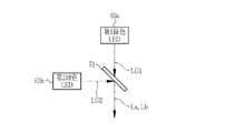
図6Aにおいて、光源部30は、第1光源51、第2光源52、第3光源53、及び第4光源54と、LED(Light Emitting Diode)駆動部55と、集光光学系56とを有している。第1〜第4光源51〜54光源は、それぞれ、紫色LED61と、第1青色LED62aと、第2青色LED62bと、第1緑色LED63aと、第2緑色LED63bと、赤色LED64とのうち、少なくともいずれかを有している。紫色LED61は、紫色光LVを発光する。第1青色LED62aは、第1青色光LB1を発光する。第2青色LED62bは、第2青色光LB2を発光する。第1緑色LED63aは、第1緑色光LG1を発光する。第2緑色LED63bは、第2緑色光LG2を発光する。赤色LED64は、赤色光LRを発光する。
In FIG. 6A, the
集光光学系56は、第1〜第4コリメータレンズ66〜69と、集光レンズ70と、第1〜第3ダイクロイックミラー(DM)71〜73とを有している。
The condensing
まず、光源部30が備える基本構成について説明する。光源部30の基本構成は、図6Bに示すように、第1緑色LED63aと、第2緑色LED63bと、第1DM71とで構成される。第1緑色LED63aが発する第1緑色光LG1の光路と、第2緑色LED63bが発する第2緑色光LG2の光路とは直交しており、この交点に第1DM71が配置されている。第1DM71の一方の面に第1緑色光LG1が45°の角度で入射し、他方の面に第2緑色光LG2が45°の角度で入射する。
First, the basic configuration of the
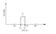
図7に示すように、第1DM71は、第1及び第2緑色光LG1,LG2の波長帯域内に第1閾値λa1と第2閾値λa2との2つの閾値を有する。第1及び緑色光LG1,LG2は、広い発光波長帯域を有する。例えば、第1緑色光LG1の発光波長帯域は、480nm〜600nmである。同様に、第2緑色光LG2の発光波長帯域は、480nm〜600nmである。第1閾値λa1は、例えば530nmである。第2閾値λa2は、例えば550nmである。第1DM71は、第1閾値λa1と第2閾値λa2との間の第1波長帯域を有する光を透過させ、第1波長帯域外の第2波長帯域を有する光を反射させる。
As shown in FIG. 7, the 1DM71 has two thresholds of a first threshold value lambda a1 and the second threshold value lambda a2 in the first and second green light LG1, LG2 within the wavelength band. The first and green lights LG1 and LG2 have wide emission wavelength bands. For example, the emission wavelength band of the first green light LG1 is 480 nm to 600 nm. Similarly, the emission wavelength band of the second green light LG2 is 480 nm to 600 nm. The first threshold λ a1 is, for example, 530 nm. The second threshold λ a2 is, for example, 550 nm. The
第1DM71は、上記の特性により、第1緑色光LG1を透過させることで、図8Aに示すように、第1波長帯域を有する第1波長帯域光Laを第1緑色光LG1から生成する。また、第1DM71は、第2緑色光LG2を反射させることで、図8Bに示すように、第2波長帯域を有する第2波長帯域光Lbを第2緑色光LG2から生成する。第1DM71は、第1波長帯域光Laの光路と、第2波長帯域光Lbの光路とを統合する。
The
以上の構成により、後述する広帯域光の発光時には、光源部30により第1緑色LED63aと第2緑色LED63bとがONとされて、図9Aに示すように、第1波長帯域光Laと第2波長帯域光Lbとが第1DM71から射出される。図8Bに示す第2波長帯域光Lbからは、第1波長帯域の光が欠損されるが、この欠損部分は、図8Aに示す第1波長帯域光Laが合波されることにより補われる。第1波長帯域光Laと第2波長帯域光Lbとが第1DM71により合波されることにより、第1及び第2緑色光LG1,LG2と同様のスペクトルが得られる。
With the above-described configuration, the first
また、後述する狭帯域光の発光時には、第1緑色LED63aと第2緑色LED63bとのうち、光源部30により第1緑色LED63aがONとされ、かつ第2緑色LED63bがOFFとされる。この場合、図9Bに示すように、第1波長帯域光Laが第1DM71から射出される。
Further, at the time of light emission of narrow band light described later, of the first
次に、光源部30の具体的な構成について説明する。第1光源51は、1つの基板60に1つの第1緑色LED63aが実装されたシングルチップ構成のLED光源である。第2光源52は、1つの基板60に第2緑色LED63bと赤色LED64が実装されたマルチチップ構成のLED光源である。第3光源53は、1つの基板60に紫色LED61と第1青色LED62aが実装されたマルチチップ構成のLED光源である。第4光源54は、1つの基板60に1つの第2青色LED62bが実装されたシングルチップ構成のLED光源である。
Next, the specific configuration of the
第1緑色LED63aと第2緑色LED63bは、同一の発光特性を有する緑色発光素子である。第1青色LED62aと第2青色LED62bは、同一の発光特性を有する青色発光素子である。なお、「同一の発光特性」とは、波長帯域がほぼ等しいことを言う。波長帯域の差異は、例えば、スペクトル幅(例えば、半値全幅)の差異に対応する。2つの光について、同じ波長帯域とは、例えば、スペクトル幅の差異が10%以下であることを言う。
The first
第1緑色LED63aは、特許請求の範囲の「第1発光素子」に対応する。第2緑色LED63bは、特許請求の範囲の「第2発光素子」に対応する。第1青色LED62aは、特許請求の範囲の「第3発光素子」に対応する。第2青色LED62bは、特許請求の範囲の「第4発光素子」に対応する。赤色LED64は、特許請求の範囲の「第5発光素子」に対応する。紫色LED61は、特許請求の範囲の「第6発光素子」に対応する。
The first
図10Aに示すように、第2光源52は、第2緑色LED63bのカソード端子と赤色LED64のカソード端子とが接続されたカソードコモン接続により構成されている。同様に、図10Bに示すように、第3光源53は、紫色LED61のカソード端子と第1青色LED62aのカソード端子とが接続されたカソードコモン接続により構成されている。
As shown in FIG. 10A, the second
したがって、第2光源52は、光源制御部31が、LED駆動部55を介して、第2緑色LED63bのアノード端子とカソード端子との間に与える駆動電流と、赤色LED64のアノード端子とカソード端子との間に与える駆動電流とを個別に制御することにより、第2緑色LED63b及び赤色LED64が個別にON/OFF可能とされている。同様に、第3光源53は、光源制御部31が、LED駆動部55を介して、紫色LED61のアノード端子とカソード端子との間に与える駆動電流と、第1青色LED62aのアノード端子とカソード端子との間に与える駆動電流とを個別に制御することにより、紫色LED61及び第1青色LED62aが個別にON/OFF可能とされている。
Therefore, with the second
紫色LED61は、例えば、発光波長帯域が380nm〜420nmであり、中心波長が405nmである紫色光LVを発光する。第1青色LED62aは、例えば、発光波長帯域が420nm〜500nmであり、中心波長が460nmである第1青色光LB1を発する。同様に、第2青色LED62bは、発光波長帯域が420nm〜500nmであり、中心波長が460nmである第2青色光LB2を発する。赤色LED64は、例えば、発光波長帯域が600nm〜650nmであり、中心波長が620nm〜630nmである赤色光LRを発する。なお、第1緑色LED63aは、上記のように発光波長帯域が480nm〜600nmである第1緑色光LG1を発する。同様に、第2緑色LED63bは、発光波長帯域が480nm〜600nmである第2緑色光LG2を発する。
The
紫色光LVの中心波長は、第1及び第2青色光LB1,LB2の波長帯域よりも短波長側にある。第1及び第2青色光LB1,LB2の中心波長は、第1及び第2緑色光LG1,LG2の波長帯域よりも短波長側にある。赤色光LRの中心波長は、第1及び第2緑色光LG1,LG2の波長帯域よりも長波長側にある。なお、各色の光は、それぞれの中心波長とピーク波長とが同じであっても良いし、異なっていても良い。 The central wavelength of the purple light LV is shorter than the wavelength band of the first and second blue lights LB1 and LB2. The central wavelengths of the first and second blue lights LB1 and LB2 are shorter than the wavelength bands of the first and second green lights LG1 and LG2. The central wavelength of the red light LR is on the longer wavelength side than the wavelength band of the first and second green light LG1 and LG2. The light of each color may have the same or different central wavelength and peak wavelength.
なお、第1緑色LED63a及び第2緑色LED63bは、それぞれ、励起光発光素子としての励起用青色LED(図示せず)と、緑色蛍光体(図示せず)とにより構成されている。励起用青色LEDは、例えば、波長帯域が450nm〜460nmの励起光を発光する。緑色蛍光体は、励起光で励起されることにより、広帯域の緑色の蛍光を発する。
The first
LED駆動部55は、光源制御部31により駆動制御され、紫色LED61、第1青色LED62a、第2青色LED62b、第1緑色LED63a、第2緑色LED63b、及び赤色LED64に対して、それぞれ独立に駆動電流を与える。光源制御部31は、紫色LED61、第1青色LED62a、第2青色LED62b、第1緑色LED63a、第2緑色LED63b、及び赤色LED64に印加する駆動電流をそれぞれ独立に設定することが可能である。紫色LED61、第1青色LED62a、第2青色LED62b、第1緑色LED63a、第2緑色LED63b、及び赤色LED64は、光源制御部31により設定された駆動電流の設定値に対応する発光強度で発光する。
The
本実施形態では、光源制御部31は、第1緑色LED63aに対して印加する駆動電流と、第2緑色LED63bに対して印加する駆動電流とを制御することにより、第1緑色光LG1と第2緑色光LG2を同じ発光強度で発光させる。また、光源制御部31は、第1青色LED62aに対して印加する駆動電流と、第2青色LED62bに対して印加する駆動電流とを制御することにより、第1青色光LB1と第2青色光LB2を同じ発光強度で発光させる。なお、「同じ発光強度」とは、LEDの個体差により生じる発光強度の差異であれば許容されることを言う。例えば、2つのLEDからそれぞれ発光される2つの光について、同じ発光強度とは、発光強度の差異が10%以下であることを言う。
In the present embodiment, the light
第1コリメータレンズ66は、第1光源51から発せられた第1光としての第1緑色光LG1を集光し、集光した第1緑色光LG1を平行光として射出する。第2コリメータレンズ67は、第2光源52から発せられた第2光としての第2緑色光LG2と、第5光としての赤色光LRとを集光し、集光した第2緑色光LG2及び赤色光LRを平行光として射出する。第3コリメータレンズ68は、第3光源53から発せられた第6光としての紫色光LVと第3光としての第1青色光LB1とを集光し、集光した紫色光LV及び第1青色光LB1を平行光として射出する。第4コリメータレンズ69は、第4光源54から発せられた第4光としての第2青色光LB2を集光し、集光した第2青色光LB2を平行光として射出する。
The
なお、第1〜第4コリメータレンズ66〜69が平行化する光は、完全に平行光でなくてもよく、実質的に平行とみなせる程度であれば良い。この平行光の平行度は、第1〜第4コリメータレンズ66〜69の各レンズ位置から、集光レンズ70の位置までの距離が長いほど、高いことが好ましい。
The light collimated by the first to
第1コリメータレンズ66から射出された第1緑色光LG1の光路と、第2コリメータレンズ67から射出された第2緑色光LG2及び赤色光LRの光路とは直交しており、この交点に第1DM71が配置されている。第1DM71の一方の面に第1緑色光LG1が45°の角度で入射し、他方の面に第2緑色光LG2及び赤色光LRが45°の角度で入射する。
The light path of the first green light LG1 emitted from the
第1DM71は、上記のように第1閾値λa1と第2閾値λa2との2つの閾値を有しており、第1緑色光LG1を透過させることで第1波長帯域光Laを生成し、第2緑色光LG2を反射させることで第2波長帯域光Lbを生成する。また、第1DM71は、図7に示すように、第2光源52からの赤色光LRをほぼ全て反射させる。第1DM71は、第1波長帯域光Laの光路と、第2波長帯域光Lb及び赤色光LRの光路とを統合する。
The
第3コリメータレンズ68から射出された第1青色光LB1及び紫色光LVの光路と、第4コリメータレンズ69から射出された第2青色光LB2の光路とは直交しており、この交点に第2DM72が配置されている。第2DM72の一方の面に紫色光LV及び第1青色光LB1が45°の角度で入射し、他方の面に第2青色光LB2が45°の角度で入射する。
The optical paths of the first blue light LB1 and the purple light LV emitted from the
第2DM72は、第1及び第2青色光LB1,LB2の波長帯域内に1つの第3閾値λbを有する。例えば、図11に示すように、第2DM72は、460nmに第3閾値λbを有する。すなわち、第2DM72は、第3閾値λbより長い波長の光を透過させ、第3閾値λb以下の波長の光を反射させる。
The
第2DM72は、上記の特性により、第1青色光LB1を反射させることで、図12Aに示すように、第3閾値λb以下の第3波長帯域を有する第3波長帯域光Lcを第1青色光LB1から生成する。また、第2DM72は、第2青色光LB2を透過させることで、図12Bに示すように、第3閾値λbより大きい第4波長帯域を有する第4波長帯域光Ldを第2青色光LB2から生成する。また、第2DM72は、第3光源53からの紫色光LVをそのまま反射させる。第2DM72は、紫色光LV及び第3波長帯域光Lcの光路と、第4波長帯域光Ldの光路とを統合する。
The 2DM72 is the above characteristics, by reflecting the first blue light LB1, as shown in FIG. 12A, the third wavelength band light Lc having the third wavelength band third threshold lambda b first blue Generate from light LB1. Also, the 2DM72, by transmitting the second blue light LB2, as shown in FIG. 12B, the fourth wavelength band light Ld having a third threshold value lambda b is larger than the fourth wavelength band from the second blue light LB2 Generate The
第1DM71により統合された光路と、第2DM72により統合された光路とは直交しており、この交点に第3DM73が配置されている。第3DM73の一方の面に第1波長帯域光La、第2波長帯域光Lb、及び赤色光LRが45°の角度で入射し、他方の面に紫色光LV、第3波長帯域光Lc、及び第4波長帯域光Ldが45°の角度で入射する。
The optical path integrated by the
第3DM73は、図13に示すように、約490nmに第4閾値λcを有する。第3DM73は、第4閾値λcより長い波長の光を透過させ、第4閾値λc以下の波長の光を反射させる。この構成により、第3DM73は、第1DM71により統合された光路と、第2DM72により統合された光路とを統合する。
The
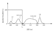
光源制御部31は、第1〜第4光源51〜54の全てをONとすることにより広帯域光(白色光または通常光ともいう)を生成する。具体的には、第1光源51をONとすると第1波長帯域光Laが第3DM73に入射される。第2光源52をONとすると第2波長帯域光Lb及び赤色光LRが第3DM73に入射される。第3光源53をONとすると紫色光LV及び第3波長帯域光Lcが第3DM73に入射される。第4光源54をONとすると第4波長帯域光Ldが第3DM73に入射される。この結果、第1波長帯域光La、第2波長帯域光Lb、赤色光LR、紫色光LV、第3波長帯域光Lc、及び第4波長帯域光Ldが第3DM73により合波されて、図14Aに示す広帯域光が生成される。
The light
ここで、第2波長帯域光Lbの欠損部分(第1波長帯域)は第1波長帯域光Laが合波されることにより補われるため、図14Aに示す広帯域光中には、第1及び第2緑色光LG1,LG2と同様のスペクトルが再現される。同様に、第4波長帯域光Ldからは、図12Bに示すように、第2DM72の第3閾値λb以下の第3波長帯域の光が欠損されるが、この欠損部分が、図12Aに示す第3波長帯域光Lcが合波されることにより補われるため、図14Aに示す広帯域光中には、第1及び第2青色光LB1,LB2と同様のスペクトルが再現される。
Here, since the loss portion (first wavelength band) of the second wavelength band light Lb is compensated by the multiplexing of the first wavelength band light La, in the wide band light shown in FIG. A spectrum similar to that of the two green lights LG1 and LG2 is reproduced. Similarly, from the fourth wavelength band light Ld, as shown in FIG. 12B, light in the third wavelength band equal to or less than the third threshold λ b of the
なお、本実施形態では、第1〜第4光源51〜54の全てをONとすることにより広帯域光を生成しているが、これに限られず、例えば、第1〜第3光源51〜53をそれぞれONとし、第4光源54をOFFとしても良い。
In the present embodiment, broadband light is generated by setting all of the first to fourth
また、光源制御部31は、第1光源51と第3光源53とをONとし、第2光源52と第4光源54とをOFFとすることにより狭帯域光を生成する。この結果、紫色光LV、第1青色光LB1、及び第1緑色光LG1が第3DM73により合波されて、図14Bに示す狭帯域光が生成される。
In addition, the light
狭帯域光のうち、紫色光LV及び第3波長帯域光Lcは、粘膜表面から浅い位置にある表層血管の観察用に最適な波長帯域の光である。一方、第1波長帯域光Laは、表層血管よりも深い位置にある中深層血管の観察用に最適な波長帯域の光である。なお、第1青色光LB1のうちの長波長成分は、粘膜と血管とのコントラストを低下させてしまうので、第2DM72を透過させることで、ライトガイド32に供給されることを防止している。
Among the narrow band light, the purple light LV and the third wavelength band light Lc are light of a wavelength band optimum for observing a superficial blood vessel located at a shallow position from the mucosal surface. On the other hand, the first wavelength band light La is light of a wavelength band optimum for observation of a middle deep blood vessel located at a position deeper than the superficial blood vessel. Note that the long wavelength component of the first blue light LB1 reduces the contrast between the mucous membrane and the blood vessel, and thus is prevented from being supplied to the
集光レンズ70は、ライトガイド32の入射端32aの近傍に配置されており、第3DM73から射出された広帯域光または狭帯域光を集光して、ライトガイド32の入射端32aに入射させる。
The condensing
内視鏡システム10は、マルチ観察モードが可能である。マルチ観察モードは、広帯域光を用いた通常観察画像と、狭帯域光とを用いた血管強調観察画像とをモニタ14に同時に表示する観察モードである。
通常観察画像は、演色性の高い広帯域光により撮像された画像である。血管強調観察画像は、上記のように、血中ヘモグロビンに対する吸光度が高い特定の波長帯域の光の成分を多く含む狭帯域光を用いているので、粘膜表面の血管や粘膜微細模様が強調表示された画像である。なお、通常観察画像は特許請求の範囲の「第1観察画像」に対応し、血管強調観察画像は特許請求の範囲の「第2観察画像」に対応する。 The normal observation image is an image captured by broadband light with high color rendering. As described above, the blood vessel-emphasized observation image uses narrow band light containing a large amount of light components in a specific wavelength band where the absorbance to blood hemoglobin is high. Image. The normal observation image corresponds to the “first observation image” in the claims, and the blood vessel-emphasized observation image corresponds to the “second observation image” in the claims.
マルチ観察モードでは、コントローラ40が光源制御部31及び撮像駆動部36を制御して、図15に示すように、広帯域光と狭帯域光とを発光させるタイミングを、撮像素子35のフレーム周期に合わせる。具体的には、コントローラ40は、撮像素子35による順次リセットの完了と信号読み出しの開始との間の期間に、広帯域光または狭帯域光を発光させる。したがって、順次リセットが完了してから信号読み出しが開始するまでの期間が露光期間である。露光期間と信号読み出し期間とリセット期間とは、1フレーム周期TF内に設けられている。
In the multi observation mode, the
光源制御部31は、広帯域光または狭帯域光を撮像素子35の露光期間に合わせて発光させ、その他の期間(信号読み出し期間及びリセット期間)に広帯域光及び狭帯域光を消灯させる。広帯域光または狭帯域光を発光させる期間が点灯期間TAであり、その他の期間が消灯期間TBである(図15参照)。すなわち、フレーム周期と同期して、点灯期間TAと消灯期間TBとが繰り返される。
The light
光源制御部31は、ある1フレーム周期TFにおいて、点灯期間TAに第1〜第4光源51〜54の全てをONとし、消灯期間TBに第1〜第4光源51〜54の全てをOFFとする。次の1フレーム周期TFにおいて、光源制御部31は、点灯期間TAに第1光源51と第3光源53をONとしかつ第2光源52と第4光源54とをOFFのままとし、消灯期間TBに第1〜第4光源51〜54の全てをOFFとする。この結果、図14Aに示す光強度スペクトルを有する広帯域光と、図14Bに示す光強度スペクトルを有する狭帯域光とが、光源部30から交互に射出され、集光レンズ70を介してライトガイド32に供給される。
The light
撮像素子35は、広帯域光の点灯期間TAに、広帯域光により照明された観察対象からの紫色光LV、第3波長帯域光Lc、及び第4波長帯域光Ldの戻り光をB画素で受光し、その後の消灯期間TBにB画素信号を出力する。同様に、撮像素子35は、広帯域光の点灯期間TAに、観察対象からの第1波長帯域光La、及び第2波長帯域光Lbの戻り光をG画素で受光し、その後の消灯期間TBにG画素信号を出力する。また、撮像素子35は、広帯域光の点灯期間TAに、観察対象からの赤色光LRの戻り光をR画素で受光し、その後の消灯期間TBにR画素信号を出力する。
The
撮像素子35は、狭帯域光の点灯期間TAに、狭帯域光により照明された観察対象からの紫色光LV及び第3波長帯域光Lcの戻り光をB画素で受光し、その後の消灯期間TBにB画素信号を出力する。同様に、撮像素子35は、狭帯域光の点灯期間TAに、観察対象からの第1波長帯域光Laの戻り光をG画素で受光し、その後の消灯期間TBにG画素信号を出力する。なお、撮像素子35は、R画素信号の出力も可能であるが、R画素信号は血管強調観察画像の生成には用いられないので、B画素信号及びG画素信号のみを出力しても良い。
The
なお、順次読み出し方式により信号読み出しが行われる信号読み出し期間と、順次リセット方式によりリセット動作が行われるリセット期間には、上記のように第1〜第4光源51〜54の全てがOFFとされる。撮像素子35はローリングシャッタ方式であるが、全ての画素行が受光可能な期間内に第1〜第4光源51〜54の発光が行われるので、実際に照明光の露光が行われる露光期間は、全画素行で同一である。したがって、上記の点灯及び消灯制御により、いわゆる同時性が確保される。
As described above, all of the first to fourth
画像処理部43は、広帯域光による観察対象の照明時に出力されたB画素信号、G画素信号、及びR画素信号に基づき通常観察画像を生成する。
The
また、画像処理部43は、狭帯域光による観察対象の照明時に出力されたB画素信号及びG画素信号に基づき血管強調観察画像を生成する。画像処理部43は、表層血管を強調するために、例えば、画像データ中のB画素信号に基づいて画像内の表層血管の領域を抽出して、抽出した表層血管の領域に対して輪郭強調処理等を施す。そして、輪郭強調処理が施されたB画素信号を、BGR画像信号を元に生成したフルカラー画像に合成する。表層血管に加えて中深層血管に対しても同様の処理を行っても良い。中深層血管を強調する場合には、中深層血管の情報が多く含まれるG画素信号から中深層血管の領域を抽出して、抽出した中深層血管の領域に対して輪郭強調処理を施す。
Further, the
表示制御部44は、画像処理部43により生成された通常観察画像と血管強調観察画像を、モニタ14に並べて表示させる。表示制御部44は、通常観察画像と血管強調観察画像がそれぞれ生成されるごとに、モニタ14に順次表示させる。これにより、モニタ14には、通常観察動画と血管強調観察動画が表示される。なお、画像処理部43によりR画素信号を用いずに、B画素信号及びG画素信号のみで血管強調観察画像を生成する場合、表示制御部44は、B画素信号をモニタ14のBチャンネル及びGチャンネルに割り当て、G画素信号をモニタ14のRチャンネルに割り当てても良い。
The
通常観察動画と血管強調観察動画の表示中にフリーズボタン17dが操作されると、コントローラ40は、フリーズボタン17dの操作直前の各画像をモニタ14に表示させることにより、画像表示をフリーズさせる。フリーズボタン17dが再度操作されると、コントローラ40は、動画表示を再開させる。
When the
次に、図16に示すフローチャートに沿って、内視鏡システム10の作用を説明する。ドクターなどのユーザが内視鏡診断を行うために内視鏡システム10を起動すると、マルチ観察モードが実行され(S11)、撮像素子35により撮像動作が開始される。
Next, the operation of the
光源制御部31は、ある1フレーム周期TFにおいて、第1〜第4光源51〜54の全てをONとする。これにより、観察部位には広帯域光が照射される(S12)。その後、撮像素子35により信号読み出し及び順次リセットが実行される(S13)。撮像素子35により信号読み出し及び順次リセットが行われている間は、光源制御部31は、第1〜第4光源51〜54の全てをOFFとする。撮像素子35は、広帯域光により照明された観察部位を撮像することにより画像信号を出力してDSP41に入力する。DSP41は、画像信号に対して画素補間処理、ガンマ補正、ホワイトバランス補正等の信号処理を施して画像データとし、フレームメモリ42に記憶させる。
The light
撮像素子35による順次リセットが完了すると、光源制御部31は、次の1フレーム周期TFにおいて、第1光源51と第3光源53とをONとさせ、第2光源52と第4光源54とをOFFのままとする。これにより、観察部位には狭帯域光が照射される(S14)。その後、撮像素子35により信号読み出し及び順次リセットが実行される(S15)。この間は、光源制御部31は、第1〜第4光源51〜54の全てをOFFとさせる。撮像素子35は、狭帯域光により照明された観察部位を撮像することにより画像信号を出力してDSP41に入力する。DSP41は、上記と同様に、画像信号に対して信号処理を施して画像データとし、フレームメモリ42に記憶させる。
When the sequential resetting by the
画像処理部43により、フレームメモリ42に記憶された画像データに基づき通常観察画像と血管強調観察画像とが生成され、表示制御部44により、通常観察画像及び血管強調観察画像がモニタ14に表示される。(S16)。
The
コントローラ40は、フリーズ操作状態か否かを判定する(S17)。フリーズ操作状態とは、ユーザによりフリーズボタン17dが操作されることで、上記ステップS12〜S16が繰り返し実行されることによりモニタ14に表示される通常観察動画及び血管強調観察動画の画像表示をフリーズさせた状態である。フリーズボタン17dが操作されてフリーズ操作状態となると(S17でYES)、コントローラ40は、通常観察動画及び血管強調観察動画の画像表示をフリーズさせ(S18)、通常観察画像と血管強調観察画像とをモニタ14に表示させる。フリーズボタン17dが再度操作されると、フリーズ操作状態が解除され、動画表示が再開される。マルチ観察モードの上記ステップS12〜S18は、診断が終了する(S19でYES)までの間、繰り返し実行される。
The
従来では、通常観察画像と血管強調観察画像とを取得するために、ダイクロイックミラーを挿抜させ、それにより広帯域光と狭帯域光とをフレーム周期に合わせて切り替えることができないので、広帯域光を発光して通常観察画像を取得する観察モードと、狭帯域光を発光して血管強調観察画像を取得する観察モードとが個別に設けられていた。このため、ユーザは、通常観察画像と血管強調観察画像とを比較するために、2つの観察モードを切り替える必要があり、取得時刻が異なる通常観察画像と血管強調観察画像とを観察せざるを得なかった。しかし、本実施形態では、光源の点灯制御により広帯域光と狭帯域光とを撮像素子のフレーム周期に合わせて瞬時に切り替えることができるので、ユーザは、観察モードを切り替えることなく、1つのマルチ観察モードでほぼ同時刻に取得された通常観察画像と血管強調観察画像とを観察することができる。 Conventionally, in order to obtain a normal observation image and a blood vessel-emphasized observation image, a dichroic mirror is inserted and removed, and thereby broadband light and narrowband light can not be switched in accordance with the frame period, so that broadband light is emitted. An observation mode for acquiring a normal observation image and an observation mode for emitting a narrow band light to acquire a blood vessel-emphasized observation image are separately provided. Therefore, the user needs to switch between the two observation modes in order to compare the normal observation image and the blood vessel-emphasized observation image, and is obliged to observe the normal observation image and the blood vessel emphasis observation image having different acquisition times. It was not. However, in the present embodiment, since the broadband light and the narrow band light can be instantaneously switched according to the frame period of the imaging device by lighting control of the light source, the user can observe one multi observation without switching the observation mode. It is possible to observe the normal observation image and the blood vessel-emphasized observation image acquired at approximately the same time in the mode.
なお、上記実施形態では、第1DM71の光反射率及び光透過率が第1閾値λa1で100%から0%に変化しているが、厳密には、第1閾値λa1で100%から0%に変化する訳ではなく、100%から0%への変化には、例えば50nm程度を要する。このため、第1DM71の光反射率と光透過率とが一致する波長、すなわち光反射率及び光透過率がほぼ50%となる波長を第1閾値λa1としても良い。なお、第2閾値λa2、第2DM72の第3閾値λb、及び第3DM73の第4閾値λcについても同様である。
Although the light reflectance and the light transmittance of the
なお、第1〜第3DM71〜73の配置は、上記実施形態で示した配置に限られない。例えば、第2コリメータレンズ67と第1DM71との間に、第3DM73を設けても良い。この場合の第3DM73は、第2波長帯域光Lb及び赤色光LRの光路と、第2DM72により統合された光路とを統合する。このため、第3DM73は、紫色光LV、第3波長帯域光Lc、第2波長帯域光Lb、及び赤色光LRを第1DM71に入射させる。第1DM71は、第3DM73により統合された光路と、第1波長帯域光Laの光路とを統合する。
The arrangement of the first to
なお、上記実施形態では、光源制御部31は、第1緑色LED63aと第2緑色LED63bに対して印加する各駆動電流を制御することにより、第1緑色光LG1と第2緑色光LG2を同じ発光強度で発光させているが、第1緑色光LG1の発光強度と第2緑色光LG2の発光強度とを異ならせても良い。同様に、光源制御部31は、第1青色LED62aと第2青色LED62bに対して印加する各駆動電流を制御することにより、第1青色光LB1と第2青色光LB2を同じ発光強度で発光させているが、第1青色光LB1の発光強度と第2青色光LB2の発光強度とを異ならせても良い。例えば、第1緑色光LG1の発光強度を第2緑色光LG2の発光強度よりも大きくし、かつ第1青色光LB1の発光強度を第2青色光LB2の発光強度よりも大きくすることにより、血管のコントラストをより高めることができる。
In the above embodiment, the light
[比較例]
以下、比較例について説明する。比較例は、光源部の構成と、光源制御部の点灯制御が上記実施形態と異なる。
[Comparative example]
The comparative example will be described below. The comparative example is different from the above embodiment in the configuration of the light source unit and the lighting control of the light source control unit.
図17に示すように、比較例の光源部100では、上記実施形態の光源部30に設けられている第1DM71に代えて、第1ハーフミラー(HM)101が設けられている。また、比較例の光源部100には、第1HM101と第1コリメータレンズ66との間に第1バンドパスフィルタ(BPF)102が付加されている。同様に、比較例の光源部100では、上記実施形態の第2DM72に代えて、第2HM103が設けられている。また、第2HM103と第3コリメータレンズ68との間に第2BPF104が付加されている。それ以外の構成は、上記実施形態と同様である。
As shown in FIG. 17, in the
第1HM101は、反射率と透過率がほぼ50%の光学部材である。第1BPF102は、第1DM71と同様の第1閾値λa1と第2閾値λa2との2つの閾値を有し、第1閾値λa1及び第2閾値λa2の間の波長帯域を透過させ、それ以外の波長帯域を吸収または反射させる。
The
上記のような第1HM101と第1BPF102の特性によって、第1光源51をONした場合は、第1緑色光LG1の一部の波長帯域成分が第1BPF102を透過することによって、第1波長帯域光Laが生成される。この第1波長帯域光Laは、第1HM101を通過することによって光量が半分になって、第3DM73に入射する。
When the
第2光源52をONした場合は、第2緑色光LG2及び赤色光LRは、第1HM101で反射されることによって光量が半分となって、第3DM73に入射する。
When the second
第2HM103は、反射率と透過率がほぼ50%の光学部材である。第2BPF104は、第2DM72と同様の1つの第3閾値λbを有し、その第3閾値λb以下の波長帯域を透過させ、それ以外の波長帯域を吸収または反射させる。
The
上記のような第2HM103と第2BPF104の特性によって、第3光源53をONした場合は、第1青色光LB1の一部の波長帯域成分が第2BPF104を透過することによって、第3波長帯域光Lcが生成される。この第3波長帯域光Lcは、第2HM103により反射されることによって光量が半分となって、第3DM73に入射する。また、紫色光LVは、第2BPF104を通過した後、第2HM103により反射されることによって光量が半分となって、第3DM73に入射する。
Due to the characteristics of the
第4光源54をONした場合は、第2青色光LB2は、第2HM103を透過することによって光量が半分となって、第3DM73に入射する。
When the fourth
光源制御部31は、比較例では、図18に示すように、広帯域光の発光時には第2光源52と第4光源54とをONとしかつ第1光源51と第3光源53とをOFFとする。この結果、第2光源52からの第2緑色光LG2と赤色光LRと、第4光源54からの第2青色光LBとが合波された広帯域光が生成される。
In the comparative example, the light
また、狭帯域光の発光時には、光源制御部31は、第1光源51と第3光源53とをONとしかつ第2光源52と第4光源54とをOFFとする。この結果、第1光源51からの第1緑色光LG1が第1BPF102を透過することによって生成される第1波長帯域光Laと、第4光源54からの第1青色光LB1が第2BPF104を透過することによって生成される第3波長帯域光Lcと、第4光源54からの紫色光LVとが合波された狭帯域光が生成される。その他の制御は上記実施形態と同様なので省略する。
Further, when narrow band light is emitted, the light
この比較例では、広帯域光は、ハーフミラーにより光量が半分になるものの、上記実施形態のように一部の波長帯域が切り取られることがないので、連続性の高い波長帯域を有する。 In this comparative example, although the broadband light has its light quantity reduced by half by the half mirror, it does not cut off a part of the wavelength band as in the above embodiment, so it has a highly continuous wavelength band.
また、上記比較例では、広帯域光の発光時には、第1〜第4光源51〜54の全てをONとさせても良い。これにより、第2青色光LB2、第2緑色光LG2、及び赤色光LRに加え、紫色光LV、第1波長帯域光La、及び第3波長帯域光Lcが合波された広帯域光がライトガイドに供給される。このような広帯域光を用いることにより、通常観察画像の血管コントラストを高めることができる。なお、この場合に、光源制御部31の制御に基づき、第1緑色LED63aに与える駆動電流の設定値と、紫色LED61及び第1青色LED62aに与える駆動電流の設定値とを大きくすることにより、血管のコントラストをより高めることができる。
Further, in the comparative example, all of the first to fourth
なお、上記実施形態及び比較例では、第2光源52には、1つの基板60に第2緑色LED63bと赤色LED64とが1つずつ設けられているが、各LEDを2以上設けても良い。同様に、第3光源53には、1つの基板60に紫色LED61と第1青色LED62aとが1つずつ設けられているが、各LEDを2以上設けても良い。
In the embodiment and the comparative example, one second
なお、上記実施形態では、第2光源52は、第2緑色LED63bのカソード端子と赤色LED64のカソード端子とが接続されているが、これに代えて、第2緑色LED63bのアノード端子と赤色LED64のアノード端子とを接続しても良い。また、第2緑色LED63bと赤色LED64のカソード端子同士を接続し、かつ第2緑色LED63bと赤色LED64のアノード端子同士を接続しても良い。同様に、第3光源53は、紫色LED61のカソード端子と第1青色LED62aのカソード端子とが接続されているが、これに代えて、紫色LED61のアノード端子と第1青色LED62aのアノード端子とを接続しても良い。また、紫色LED61と第1青色LED62aのカソード端子同士を接続し、かつ紫色LED61と第1青色LED62aのアノード端子同士を接続しても良い。
In the above embodiment, the second
また、第2光源52は、マルチチップ構成とせずに、第2緑色LED63bと赤色LED64とを別々の基板に1つずつ設けたシングルチップ構成としても良い。この場合には、第2緑色LED63bが発する第2緑色光LG2の光路と、赤色LED64が発する赤色光LRの光路とを統合するダイクロイックミラーが付加される。同様に、第3光源53は、マルチチップ構成とせずに、紫色LED61と第1青色LED62aとを別々の基板に1つずつ設けたシングルチップ構成としても良い。この場合、紫色LED61が発する紫色光LVの光路と、第1青色LED62aが発する第1青色光LB1の光路とを統合するダイクロイックミラーが付加される。
The second
なお、上記実施形態及び比較例では、光源制御部31は、点灯期間TAを撮像素子35の露光期間に合わせているが、点灯期間TAは露光期間内であれば適宜変更可能である。例えば、光源制御部31は、撮像素子35の露光期間内において、点灯期間TAの開始タイミングを露光期間の開始タイミングに合わせ、かつ点灯期間TAの終了タイミングを露光期間の終了タイミングよりも早くることにより、点灯期間TAを短縮させても良い。また、点灯期間TAの開始タイミングを露光期間の開始タイミングよりも送らせ、かつ点灯期間TAの終了タイミングを露光期間の終了タイミングに合わせることにより、点灯期間TAを短縮させても良い。
In the above embodiment and the comparative example, the light
なお、上記実施形態及び比較例では、内視鏡システム10は、マルチ観察モードを実行可能としているが、マルチ観察モードの他、通常光観察モードと、血管強調観察モードとを可能としても良い。通常光観察モードは、広帯域光を照明光として用いることにより、通常観察画像をモニタ14に表示させる観察モードである。血管強調観察モードは、狭帯域光を照明光として用いることにより、血管強調観察画像をモニタ14に表示させる観察モードである。これらの観察モードは、操作入力部15等により選択可能である。
In the embodiment and the comparative example, the
なお、上記実施形態及び比較例では、撮像素子35に、原色型のカラーフィルタアレイ39を設けているが、これに代えて、補色型のカラーフィルタアレイを設けても良い。
In the embodiment and the comparative example, the primary
10 内視鏡システム
11 内視鏡
12 プロセッサ装置
13 光源装置
14 モニタ
15 操作入力部
16 挿入部
17 操作部
17a アングルノブ
17b 鉗子口
17c 送気・送水ボタン
17d フリーズボタン
18 ユニバーサルコード
19 先端部
20 湾曲部
21 可撓管部
22 照明窓
23 観察窓
24 送気・送水ノズル
25 鉗子出口
29 コネクタ
29a 通信用コネクタ
29b 光源用コネクタ
30、100 光源部
31 光源制御部
32 ライトガイド
32a 入射端
33 照射レンズ
34 対物光学系
35 撮像素子
35a 撮像面
36 撮像駆動部
38 画素
39 カラーフィルタアレイ
39a 青色フィルタ
39b 緑色フィルタ
39c 赤色フィルタ
40 コントローラ
41 DSP
42 フレームメモリ
43 画像処理部
44 表示制御部
51 第1光源
52 第2光源
54 第4光源
55 LED駆動部
56 集光光学系
61 紫色LED
62a 第1青色LED
62b 第2青色LED
63a 第1緑色LED
63b 第2緑色LED
64 赤色LED
66 第1コリメータレンズ
67 第2コリメータレンズ
68 第3コリメータレンズ
69 第4コリメータレンズ
70 集光レンズ
71 第1ダイクロイックミラー
72 第2ダイクロイックミラー
73 第3ダイクロイックミラー
101 第1ハーフミラー
102 第1バンドパスフィルタ
103 第2ハーフミラー
104 第2バンドパスフィルタ
42
62a 1st blue LED
62b 2nd blue LED
63a 1st green LED
63b 2nd green LED
64 red LED
66
Claims (9)
前記第1光と同じ波長帯域を有する第2光を発する第2発光素子を有する第2光源と、
前記第1光及び前記第2光の波長帯域よりも中心波長が短波長側にある第3光を発する第3発光素子を有する第3光源と、
前記第3光と同じ波長帯域を有する第4光を発する第4発光素子を有する第4光源と、
前記第1光及び前記第2光の波長帯域内に第1閾値及び第2閾値を有する第1ダイクロイックミラーであって、前記第1閾値及び前記第2閾値の間の第1波長帯域を有する第1波長帯域光を前記第1光から生成し、前記第1波長帯域外の第2波長帯域を有する第2波長帯域光を前記第2光から生成し、前記第1波長帯域光の光路と前記第2波長帯域光の光路とを統合する第1ダイクロイックミラーと、
前記第3光及び前記第4光の波長帯域内に第3閾値を有し、前記第3閾値以下の第3波長帯域を有する第3波長帯域光を前記第3光から生成し、前記第3閾値より大きい第4波長帯域を有する第4波長帯域光を前記第4光から生成し、前記第3波長帯域光の光路と前記第4波長帯域光の光路とを統合させる第2ダイクロイックミラーと、
前記第1発光素子及び前記第2発光素子を駆動させて、前記第1波長帯域光及び前記第2波長帯域光を含む広帯域光を生成させる制御と、前記第1発光素子及び前記第2発光素子のうち、前記第1発光素子を駆動させて、前記第1波長帯域光を含む狭帯域光を生成させる制御とを行い、前記第1発光素子に対して印加する駆動電流と、前記第2発光素子に対して印加する駆動電流とを制御することにより、前記第1光と前記第2光を同じ発光強度で発光させる光源制御部と、
を備える内視鏡用光源装置。 A first light source having a first light emitting element that emits a first light;
A second light source having a second light emitting element that emits a second light having the same wavelength band as the first light;
A third light source having a third light emitting element that emits a third light whose center wavelength is shorter than the wavelength bands of the first light and the second light;
A fourth light source having a fourth light emitting element that emits fourth light having the same wavelength band as the third light;
A first dichroic mirror having a first threshold and a second threshold within wavelength bands of the first light and the second light, the first dichroic mirror having a first wavelength band between the first threshold and the second threshold One wavelength band light is generated from the first light, and a second wavelength band light having a second wavelength band outside the first wavelength band is generated from the second light, and an optical path of the first wavelength band light and the above A first dichroic mirror that integrates the light path of the second wavelength band light;
A third wavelength band light having a third threshold in a wavelength band of the third light and the fourth light and having a third wavelength band less than the third threshold is generated from the third light, and the third light is generated. A second dichroic mirror that generates fourth wavelength band light having a fourth wavelength band larger than a threshold from the fourth light, and integrates the optical path of the third wavelength band light and the optical path of the fourth wavelength band light;
Control to drive the first light emitting element and the second light emitting element to generate wide band light including the first wavelength band light and the second wavelength band light, the first light emitting element and the second light emitting element of the first and the light-emitting element is driven, have rows and a control to generate the narrow-band light including the first wavelength band, and a drive current applied to the first light emitting element, the second A light source control unit configured to emit the first light and the second light with the same light emission intensity by controlling a drive current applied to the light emitting element ;
A light source device for an endoscope, comprising:
前記光源制御部は、前記第1〜第4発光素子をそれぞれ駆動させて、前記第1〜第4波長帯域光を含む広帯域光を生成させる制御と、前記第1〜第4発光素子のうち、前記第1発光素子及び前記第3発光素子を駆動させて、前記第1波長帯域光及び前記第3波長帯域光を含む狭帯域光を生成させる制御とを行う請求項1または2に記載の内視鏡用光源装置。 And a third dichroic mirror that integrates an optical path integrated by the first dichroic mirror and an optical path integrated by the second dichroic mirror,
The light source control unit controls the first to fourth light emitting elements to generate broadband light including the first to fourth wavelength bands, and the first to fourth light emitting elements. The control according to claim 1 or 2 , wherein the first light emitting element and the third light emitting element are driven to generate narrow band light including the first wavelength band light and the third wavelength band light. Light source device for endoscopes.
前記光源制御部は、前記第1〜第5発光素子をそれぞれ駆動させて、前記第1〜第4波長帯域光及び前記第5光を含む広帯域光を生成させる制御を行う請求項3に記載の内視鏡用光源装置。 The second light source further includes a fifth light emitting element that emits fifth light whose center wavelength is on the longer wavelength side than the wavelength bands of the first light and the second light,
The light source control part, the first through fifth respectively to drive the light emitting device, according to claim 3 for controlling to generate a broadband light including the first to fourth wavelength band and the fifth light Light source device for endoscopes.
前記光源制御部は、前記第1〜第6発光素子をそれぞれ駆動させて、前記第1〜第4波長帯域光、前記第5光、及び前記第6光を含む広帯域光を生成させる制御と、前記第1〜
第6発光素子のうち、前記第1発光素子、前記第3発光素子、及び前記第6発光素子を駆動させて、前記第1波長帯域光、前記第3波長帯域光、及び前記第6光を含む狭帯域光を生成させる制御とを行う請求項4に記載の内視鏡用光源装置。 The third light source further includes a sixth light emitting element that emits sixth light having a center wavelength shorter than that of the wavelength bands of the third light and the fourth light,
The light source control unit controls the first to sixth light emitting elements to generate broadband light including the first to fourth wavelength band light, the fifth light, and the sixth light; Said 1st-
Among the sixth light emitting elements, the first light emitting element, the third light emitting element, and the sixth light emitting element are driven to generate the first wavelength band light, the third wavelength band light, and the sixth light. The light source device for endoscopes according to claim 4 which performs control which generates narrow band light including.
前記第1光と同じ波長帯域を有する第2光を発する第2発光素子を有する第2光源と、
前記第1光及び前記第2光の波長帯域よりも中心波長が短波長側にある第3光を発する第3発光素子を有する第3光源と、
前記第3光と同じ波長帯域を有する第4光を発する第4発光素子を有する第4光源と、
前記第1光及び前記第2光の波長帯域内に第1閾値及び第2閾値を有する第1ダイクロイックミラーであって、前記第1閾値及び前記第2閾値の間の第1波長帯域を有する第1波長帯域光を前記第1光から生成し、前記第1波長帯域外の第2波長帯域を有する第2波長帯域光を前記第2光から生成し、前記第1波長帯域光の光路と前記第2波長帯域光の光路とを統合する第1ダイクロイックミラーと、
前記第3光及び前記第4光の波長帯域内に第3閾値を有し、前記第3閾値以下の第3波長帯域を有する第3波長帯域光を前記第3光から生成し、前記第3閾値より大きい第4波長帯域を有する第4波長帯域光を前記第4光から生成し、前記第3波長帯域光の光路と前記第4波長帯域光の光路とを統合させる第2ダイクロイックミラーと、
を備える内視鏡用光源装置の作動方法において、
光源制御部が、前記第1発光素子と前記第2発光素子とを駆動させて前記第1波長帯域光及び前記第2波長帯域光を含む広帯域光を生成させる制御と、前記第1発光素子及び前記第2発光素子のうち前記第1発光素子を駆動させて前記第1波長帯域光を含む狭帯域光を生成させる制御とを行い、前記第1発光素子に対して印加する駆動電流と、前記第2発光素子に対して印加する駆動電流とを制御することにより、前記第1光と前記第2光を同じ発光強度で発光させる内視鏡用光源装置の作動方法。 A first light source having a first light emitting element that emits a first light;
A second light source having a second light emitting element that emits a second light having the same wavelength band as the first light;
A third light source having a third light emitting element that emits a third light whose center wavelength is shorter than the wavelength bands of the first light and the second light;
A fourth light source having a fourth light emitting element that emits fourth light having the same wavelength band as the third light;
A first dichroic mirror having a first threshold and a second threshold within wavelength bands of the first light and the second light, the first dichroic mirror having a first wavelength band between the first threshold and the second threshold One wavelength band light is generated from the first light, and a second wavelength band light having a second wavelength band outside the first wavelength band is generated from the second light, and an optical path of the first wavelength band light and the above A first dichroic mirror that integrates the light path of the second wavelength band light;
A third wavelength band light having a third threshold in a wavelength band of the third light and the fourth light and having a third wavelength band less than the third threshold is generated from the third light, and the third light is generated. A second dichroic mirror that generates fourth wavelength band light having a fourth wavelength band larger than a threshold from the fourth light, and integrates the optical path of the third wavelength band light and the optical path of the fourth wavelength band light;
In a method of operating a light source device for an endoscope, comprising:
A light source control unit controls the first light emitting element and the second light emitting element to generate broadband light including the first wavelength band light and the second wavelength band light; There line and a control for generating a narrow-band light including by driving the first light emitting element and the first wavelength band light of the second light emitting element, a driving current applied to the first light emitting element, A method of operating a light source device for an endoscope, which emits the first light and the second light with the same light emission intensity by controlling a drive current applied to the second light emitting element .
観察対象を撮像して画像信号を出力する撮像素子を有する内視鏡と、
前記広帯域光により照明された観察対象を前記撮像素子が撮像して得た前記画像信号に基づいて第1観察画像を生成し、かつ前記狭帯域光により照明された観察対象を前記撮像素子が撮像して得た前記画像信号に基づいて第2観察画像を生成する画像処理部と、
を備える内視鏡システム。 The light source device for endoscopes according to any one of claims 1 to 6 ,
An endoscope having an imaging element that images an observation target and outputs an image signal;
A first observation image is generated based on the image signal obtained by the imaging device imaging the observation object illuminated by the wide band light, and the imaging device images the observation object illuminated by the narrow band light An image processing unit that generates a second observation image based on the image signal obtained by
An endoscope system comprising:
前記光源制御部は、前記1フレーム周期ごとに、前記第1発光素子と前記第2発光素子とを制御して、前記広帯域光と前記狭帯域光とを交互に生成させる請求項8に記載の内視鏡システム。 The imaging device includes an imaging drive unit that causes the imaging device to perform an imaging operation every one frame period.
9. The light source control unit according to claim 8 , wherein the broad band light and the narrow band light are alternately generated by controlling the first light emitting element and the second light emitting element for each one frame period. Endoscope system.
Priority Applications (1)
| Application Number | Priority Date | Filing Date | Title |
|---|---|---|---|
| JP2015254814A JP6533157B2 (en) | 2015-12-25 | 2015-12-25 | LIGHT SOURCE DEVICE FOR ENDOSCOPE, OPERATION METHOD THEREOF, AND ENDOSCOPE SYSTEM |
Applications Claiming Priority (1)
| Application Number | Priority Date | Filing Date | Title |
|---|---|---|---|
| JP2015254814A JP6533157B2 (en) | 2015-12-25 | 2015-12-25 | LIGHT SOURCE DEVICE FOR ENDOSCOPE, OPERATION METHOD THEREOF, AND ENDOSCOPE SYSTEM |
Publications (2)
| Publication Number | Publication Date |
|---|---|
| JP2017113458A JP2017113458A (en) | 2017-06-29 |
| JP6533157B2 true JP6533157B2 (en) | 2019-06-19 |
Family
ID=59232555
Family Applications (1)
| Application Number | Title | Priority Date | Filing Date |
|---|---|---|---|
| JP2015254814A Active JP6533157B2 (en) | 2015-12-25 | 2015-12-25 | LIGHT SOURCE DEVICE FOR ENDOSCOPE, OPERATION METHOD THEREOF, AND ENDOSCOPE SYSTEM |
Country Status (1)
| Country | Link |
|---|---|
| JP (1) | JP6533157B2 (en) |
Families Citing this family (1)
| Publication number | Priority date | Publication date | Assignee | Title |
|---|---|---|---|---|
| CN113366366B (en) * | 2019-01-30 | 2023-04-28 | 富士胶片株式会社 | Endoscope system |
Family Cites Families (4)
| Publication number | Priority date | Publication date | Assignee | Title |
|---|---|---|---|---|
| CN102753082B (en) * | 2010-10-26 | 2016-10-12 | 奥林巴斯株式会社 | Endoscope |
| JP5654167B1 (en) * | 2013-07-03 | 2015-01-14 | 富士フイルム株式会社 | Endoscope system and operating method thereof |
| JP5976045B2 (en) * | 2013-08-27 | 2016-08-23 | 富士フイルム株式会社 | Endoscope light source device and endoscope system using the same |
| CN106999029A (en) * | 2015-05-28 | 2017-08-01 | 奥林巴斯株式会社 | Light supply apparatus |
-
2015
- 2015-12-25 JP JP2015254814A patent/JP6533157B2/en active Active
Also Published As
| Publication number | Publication date |
|---|---|
| JP2017113458A (en) | 2017-06-29 |
Similar Documents
| Publication | Publication Date | Title |
|---|---|---|
| JP5371946B2 (en) | Endoscopic diagnosis device | |
| JP5496075B2 (en) | Endoscopic diagnosis device | |
| JP5460506B2 (en) | Endoscope apparatus operating method and endoscope apparatus | |
| US9943230B2 (en) | Endoscope system, processor device of endoscope system, and image processing method | |
| JP5303012B2 (en) | Endoscope system, processor device for endoscope system, and method for operating endoscope system | |
| JP5997676B2 (en) | Endoscope light source device and endoscope system using the same | |
| US9326664B2 (en) | Endoscope apparatus | |
| JP6435275B2 (en) | Endoscope device | |
| JP5331904B2 (en) | Endoscope system and method for operating endoscope system | |
| JP6505792B2 (en) | LIGHT SOURCE DEVICE FOR ENDOSCOPE AND ENDOSCOPE SYSTEM | |
| JP4709606B2 (en) | Biological observation device | |
| EP2433556A1 (en) | Electronic endoscope system | |
| WO2015016013A1 (en) | Endoscope light source device and endoscope system using same | |
| WO2007010709A1 (en) | Endoscope and endoscope device | |
| WO2013084566A1 (en) | Endoscope device | |
| JP5850630B2 (en) | Endoscope system and driving method thereof | |
| JPWO2019069414A1 (en) | Endoscope equipment, image processing methods and programs | |
| JP5921984B2 (en) | Electronic endoscope apparatus and illumination apparatus | |
| JP6560968B2 (en) | Endoscope system and operating method thereof | |
| JP6099586B2 (en) | Endoscope light source device and endoscope system | |
| JP6533157B2 (en) | LIGHT SOURCE DEVICE FOR ENDOSCOPE, OPERATION METHOD THEREOF, AND ENDOSCOPE SYSTEM | |
| JP2012065899A (en) | Electronic endoscope system | |
| JP6277068B2 (en) | Endoscope light source device and endoscope system | |
| JP6141220B2 (en) | Endoscope light source device and endoscope system | |
| WO2020217852A1 (en) | Endoscope light source device and endoscope system |
Legal Events
| Date | Code | Title | Description |
|---|---|---|---|
| A621 | Written request for application examination |
Free format text: JAPANESE INTERMEDIATE CODE: A621 Effective date: 20180219 |
|
| A977 | Report on retrieval |
Free format text: JAPANESE INTERMEDIATE CODE: A971007 Effective date: 20181128 |
|
| A131 | Notification of reasons for refusal |
Free format text: JAPANESE INTERMEDIATE CODE: A131 Effective date: 20181211 |
|
| A521 | Request for written amendment filed |
Free format text: JAPANESE INTERMEDIATE CODE: A523 Effective date: 20190206 |
|
| TRDD | Decision of grant or rejection written | ||
| A01 | Written decision to grant a patent or to grant a registration (utility model) |
Free format text: JAPANESE INTERMEDIATE CODE: A01 Effective date: 20190507 |
|
| A61 | First payment of annual fees (during grant procedure) |
Free format text: JAPANESE INTERMEDIATE CODE: A61 Effective date: 20190523 |
|
| R150 | Certificate of patent or registration of utility model |
Ref document number: 6533157 Country of ref document: JP Free format text: JAPANESE INTERMEDIATE CODE: R150 |
|
| R250 | Receipt of annual fees |
Free format text: JAPANESE INTERMEDIATE CODE: R250 |
|
| R250 | Receipt of annual fees |
Free format text: JAPANESE INTERMEDIATE CODE: R250 |