EP3639682A1 - Vaporizer and electronic cigarette using same - Google Patents
Vaporizer and electronic cigarette using same Download PDFInfo
- Publication number
- EP3639682A1 EP3639682A1 EP18816898.3A EP18816898A EP3639682A1 EP 3639682 A1 EP3639682 A1 EP 3639682A1 EP 18816898 A EP18816898 A EP 18816898A EP 3639682 A1 EP3639682 A1 EP 3639682A1
- Authority
- EP
- European Patent Office
- Prior art keywords
- groove
- connecting member
- inner lining
- atomizer
- limiting
- Prior art date
- Legal status (The legal status is an assumption and is not a legal conclusion. Google has not performed a legal analysis and makes no representation as to the accuracy of the status listed.)
- Withdrawn
Links
- 239000003571 electronic cigarette Substances 0.000 title claims abstract description 11
- 239000006200 vaporizer Substances 0.000 title abstract 4
- 239000007788 liquid Substances 0.000 claims abstract description 82
- 238000004891 communication Methods 0.000 claims abstract description 11
- 238000007789 sealing Methods 0.000 claims description 23
- 238000002347 injection Methods 0.000 description 29
- 239000007924 injection Substances 0.000 description 29
- VYPSYNLAJGMNEJ-UHFFFAOYSA-N Silicium dioxide Chemical compound O=[Si]=O VYPSYNLAJGMNEJ-UHFFFAOYSA-N 0.000 description 2
- 241000208125 Nicotiana Species 0.000 description 1
- 235000002637 Nicotiana tabacum Nutrition 0.000 description 1
- 238000010276 construction Methods 0.000 description 1
- 230000000694 effects Effects 0.000 description 1
- 239000000463 material Substances 0.000 description 1
- 238000012986 modification Methods 0.000 description 1
- 230000004048 modification Effects 0.000 description 1
- 230000002093 peripheral effect Effects 0.000 description 1
- 239000000377 silicon dioxide Substances 0.000 description 1
- 238000004088 simulation Methods 0.000 description 1
- 230000000391 smoking effect Effects 0.000 description 1
- 239000000243 solution Substances 0.000 description 1
Images





Classifications
-
- A—HUMAN NECESSITIES
- A24—TOBACCO; CIGARS; CIGARETTES; SIMULATED SMOKING DEVICES; SMOKERS' REQUISITES
- A24F—SMOKERS' REQUISITES; MATCH BOXES; SIMULATED SMOKING DEVICES
- A24F40/00—Electrically operated smoking devices; Component parts thereof; Manufacture thereof; Maintenance or testing thereof; Charging means specially adapted therefor
- A24F40/40—Constructional details, e.g. connection of cartridges and battery parts
- A24F40/49—Child proofing
-
- A—HUMAN NECESSITIES
- A24—TOBACCO; CIGARS; CIGARETTES; SIMULATED SMOKING DEVICES; SMOKERS' REQUISITES
- A24F—SMOKERS' REQUISITES; MATCH BOXES; SIMULATED SMOKING DEVICES
- A24F15/00—Receptacles or boxes specially adapted for cigars, cigarettes, simulated smoking devices or cigarettes therefor
- A24F15/01—Receptacles or boxes specially adapted for cigars, cigarettes, simulated smoking devices or cigarettes therefor specially adapted for simulated smoking devices or cigarettes therefor
- A24F15/015—Receptacles or boxes specially adapted for cigars, cigarettes, simulated smoking devices or cigarettes therefor specially adapted for simulated smoking devices or cigarettes therefor with means for refilling of liquid inhalable precursors
-
- A—HUMAN NECESSITIES
- A24—TOBACCO; CIGARS; CIGARETTES; SIMULATED SMOKING DEVICES; SMOKERS' REQUISITES
- A24F—SMOKERS' REQUISITES; MATCH BOXES; SIMULATED SMOKING DEVICES
- A24F40/00—Electrically operated smoking devices; Component parts thereof; Manufacture thereof; Maintenance or testing thereof; Charging means specially adapted therefor
- A24F40/10—Devices using liquid inhalable precursors
-
- A—HUMAN NECESSITIES
- A24—TOBACCO; CIGARS; CIGARETTES; SIMULATED SMOKING DEVICES; SMOKERS' REQUISITES
- A24F—SMOKERS' REQUISITES; MATCH BOXES; SIMULATED SMOKING DEVICES
- A24F40/00—Electrically operated smoking devices; Component parts thereof; Manufacture thereof; Maintenance or testing thereof; Charging means specially adapted therefor
- A24F40/40—Constructional details, e.g. connection of cartridges and battery parts
- A24F40/48—Fluid transfer means, e.g. pumps
- A24F40/485—Valves; Apertures
Definitions
- the present application relates to the technical field of smoking simulation, and more particularly, relates to an atomizer and an electronic cigarette using the atomizer.
- the liquid injection modes of most atomizers are bottom liquid injection, side surface liquid injection or top liquid injection.
- most of the atomizers adopt a bottom liquid injection.
- most of the atomizers adopt the top liquid injection and the side surface liquid injection.
- the top of the atomizer should be opened or rotated to a designated position, and then the liquid injection is performed. After the liquid injection is finished, the top of the atomizer should be restored to the original position.
- it is more convenient and clean relative to the top liquid injection or the side surface liquid injection.
- the operation is very inconvenient, the frequent operation reduces the user's experience to the product.
- the children protection function is often ignored. Children can open the atomizer and contact the tobacco liquid easily, there is a safety hazard.
- An atomizer includes an upper cover assembly, a base assembly and an atomizer head.
- a liquid storage chamber is provided in the atomizer.
- the upper cover assembly includes an inner lining member and a connecting member.
- the connecting member is provided with a first liquid intake hole in communication with the liquid storage chamber.
- the inner lining member is provided with a positioning hole and a first sliding groove.
- the connecting member is provided with a rotating shaft mounted in the positioning hole and a limiting shaft mounted in the first limiting groove.
- the first sliding groove includes a translation groove and a rotation groove in communication with the translation groove.
- the positioning hole is a waist-shaped hole
- the first sliding groove is an L-shaped groove
- the connecting member is provided with a latching groove and the inner lining member is provided with a latching clip corresponding to the latching groove, or, the connecting member is provided with a latching clip and the inner lining member is provided with a latching groove corresponding to the latching clip.
- the latching clip is latched in the latching groove to cause the inner lining member to remain a closed state relative to the connecting member.
- a sealing member is provided in the connecting member.
- the sealing member is provided with a second liquid intake hole corresponding to the first liquid intake hole.
- the connecting member is provided with a receiving portion.
- the sealing member is hermetically positioned in the receiving portion.
- the connecting member is provided with an elastic member.
- An end of the elastic member is fixed to the connecting member, and an opposite end of the elastic member is provided with a limiting member.
- the inner lining member is provided with a matching groove corresponding to the limiting member.
- the number of the matching groove is two.
- the positions of the two matching grooves are respectively corresponding to the positions of the limiting member when the first liquid intake hole is opened or closed.
- the connecting member is provided with a mounting hole.
- the elastic member is positioned in the mounting hole. A part of the limiting member is exposed outside the mounting hole.
- An electronic cigarette includes any one of the aforementioned atomizers.
- an atomizer is further provided.
- the atomizer includes an upper cover assembly, a base assembly and an atomizer head.
- the upper cover assembly and the base assembly are respectively mounted on opposite ends of the atomizer head.
- a liquid storage chamber is provided in the atomizer.
- the upper cover assembly includes an inner lining member and a connecting member.
- the connecting member is provided with a first liquid intake hole in communication with the liquid storage chamber.
- the connecting member is provided with a rotating shaft and a limiting shaft.
- the inner lining member is provided with a first sliding groove.
- the limiting shaft extends through the first sliding groove.
- the inner lining member is rotatably connected to the rotating shaft. When the inner lining member is rotated relative to the connecting member, the limiting shaft slides along the first sliding groove so as to open or close the first liquid intake hole.
- the liquid intake hole can be opened or closed by rotating the upper cover, the liquid injection operation is much simply and convenient.
- the connecting member is provided with a latching groove and the inner lining member is provided with a latching clip corresponding to the latching groove.
- the latching clip is latched in the latching groove to cause the inner lining member to remain a closed state relative to the connecting member.
- a sealing member is provided in the connecting member.
- the sealing member is provided with a second liquid intake hole corresponding to the first liquid intake hole.
- the connecting member is provided with a receiving portion.
- the sealing member is hermetically positioned in the receiving portion.
- the connecting member is provided with an elastic member.
- An end of the elastic member is fixed to the connecting member, and an opposite end of the elastic member is provided with a limiting member.
- the inner lining member is provided with a matching groove corresponding to the limiting member.
- the number of the matching groove is two.
- the positions of the two matching grooves are respectively corresponding to the positions of the limiting member when the first liquid intake hole is opened or closed.
- the elastic member is a spring.
- the connecting member is provided with a mounting hole.
- the limiting member is a roll ball.
- the elastic member is positioned in the mounting hole. A part of the limiting member is exposed outside the mounting hole.
- the upper cover assembly further includes an upper cover, the upper cover is positioned on the inner lining member, and the inner lining member is embedded in the upper cover.
- An electronic cigarette includes any one of the aforementioned atomizers.
- the present application provides an electronic cigarette (not shown).
- the electronic cigarette includes an atomizer 100 and a battery assembly (not shown) electrically connected to the atomizer 100.
- the atomizer 100 includes an upper cover assembly 10, a base assembly 30, an atomizer head (not shown), and a sleeve pipe 20.
- the upper cover assembly 10 and the base assembly 30 are respectively mounted on opposite ends of the atomizer head.
- the sleeve pipe 20 is sleeved outside the atomizer head.
- the upper cover assembly 10 includes a mouth piece 11, an upper cover 12, an inner lining member 13 and a connecting member 15.
- the mouth piece 11 is detachably connected to the upper cover 12.
- the upper cover 12 is connected to an upper end of the inner lining member 13.
- the inner lining member 13 is rotatably connected to the connecting member 15.
- Both the mouth piece 11 and the upper cover 12 substantially have a cylindrical structure with two opening ends.
- the upper cover 12 is in communication with the mouth piece 11.
- the mouth piece 11 is sleeved on the outside of the upper cover 12.
- the connecting member 15 substantially has a cylindrical structure with two opening ends.
- the lower end of the connecting member 15 is connected to the atomizer head.
- a liquid storage chamber (not shown) is formed between the connecting member 15 and the sleeve pipe 20.
- the upper end surface of the connecting member 15 is provided with a receiving portion 151.
- a sealing member 14 having a shape matching the receiving portion 151 is positioned in the receiving portion 151. The sealing member 14 can engage with the connecting member 15 via an interference fit.
- the receiving portion 151 is provided with a first liquid intake hole 152 at the bottom, and the first liquid intake hole 152 is in communication with the liquid storage chamber.
- the side wall of the receiving portion 151 is provided with a latching groove 153.
- a rotating shaft 16 and a limiting shaft 17 are provided on the upper end surface of the connecting member 15.
- the upper end surface of the connecting member 15 is further provided with a mounting hole 154.
- An elastic member 18 is provided in the mounting hole 154, a limiting member 19 is fixed to an upper end of the elastic member 18, and a part of the limiting member 19 is exposed outside the mounting hole 154.
- the limiting member 19 can be a spherical member, such as a roll ball, for facilitating the limiting member 19 to perform a movement in the mounting hole 154 with a small friction force.
- both the rotating shaft 16 and the limiting shaft 17 are screws, the connecting member 15 is provided with a threaded hole 155 corresponding to each of the rotating shaft 16 and the limiting shaft 17.
- the sealing member 14 is provided with a second liquid intake hole 141 corresponding to the first liquid intake hole 152.
- the upper surface of the sealing member 14 is provided with a second sliding groove 142.
- the second sliding groove 142 passes through a peripheral surface of the sealing member 14, such that one end of the second sliding groove 142 is in communication with the latching groove 153.
- the sealing member 14 is made of silica material.
- the inner lining member 13 substantially has a cylindrical structure with two opening ends.
- the inner lining member 13 is provided with a positioning hole 131 corresponding to the rotating shaft 16 and a first sliding groove 132 corresponding to the limiting shaft 17. Both the positioning hole 131 and the first sliding groove 132 pass through opposite end surfaces of the inner lining member 13 along an axial direction of the inner lining member 13.
- the inner lining member 13 is rotatably connected to the rotating shaft 16, and the limiting shaft 17 can slide along the first sliding groove 132.
- the lower end surface of the inner lining member 13 is provided with two matching grooves 134, and the positions of the two matching grooves 134 are respectively corresponding to the positions of the elastic member 18 when the first liquid intake hole 152 is opened or closed.
- An edge of the lower end surface of the inner lining member 13 is provided with a latching clip 133.
- the latching clip 133 can slide along the second sliding groove 142 to enter the latching groove 153 located at one end of the second sliding groove 142, thereby locking the inner lining member 13 to the connecting member 15.
- the upper cover 12 when a liquid injection operation is performed, the upper cover 12 is rotated, to enable the upper cover 12 and the inner lining member 13 to rotate relative to the connecting member 15 around a center of the rotating shaft 16.
- the latching clip 133 slides from the latching groove 153 into the second sliding groove 142, thereby unlocking the inner lining member 13 and the connecting member 15.
- the elastic member 18 is compressed by the inner lining member 13 to improve a hand feeling, the limiting shaft 17 slides along the first sliding groove 132, and at the same time, the latching clip 133 slides along the second sliding groove 142.
- the elastic member 18 When the first liquid intake hole 152 and the second liquid intake hole 141 are opened completely, the elastic member 18 is positioned in one of the matching grooves 134, in order to prevent the inner lining member 13 from rotating randomly to cover the second liquid intake hole 141 and accordingly influence the liquid injection operation, such that it is convenient to perform the liquid injection operation. As the limiting member 19 engages in one of the matching grooves 134, a vibration and a sound may send out, to remind the user that the inner lining member 13 has reached the right position.
- the elastic member 18 can be members having elasticity restoring function, such as a spring or a rubber.
- the upper cover 12 is rotated in a reversed direction, the latching clip 133 enters the latching groove 153 by passing through the second sliding groove 142, the latching clip 133 locks the inner lining member 13 and the connecting member 15, and the elastic member 18 engages in the other one of the matching grooves 134.
- the upper cover 12 is pushed to slide from the lateral side, so that the second liquid intake hole 141 is exposed for performing a liquid injection operation.
- the liquid injection operation is more convenient and easier.
- the rotatable inner lining member 13 is located inside the upper cover assembly 10, thereby ensuring an integrity of the outer appearance of the product.
- the first sliding groove 132 and the positioning hole 131 each have a shape different from that of the first embodiment.
- the mounting hole 154, the elastic member 18 and the elastic member 19 in the connecting member 15 are omitted, and the matching grooves 134 in the lower end surface of the inner lining member 13 are omitted.
- the positioning hole 131 is a waist-shaped hole.
- the first sliding groove 132 is substantially L-shaped and includes a translation groove 1321 and a rotation groove 1322 in communication with the translation groove 1321.
- the positioning hole 131 is parallel to the translation groove 1321.
- the upper cover 12 when a liquid injection operation is required, the upper cover 12 is pushed from the lateral side.
- the latching clip 133 enters the second sliding groove 142 from the latching groove 153, thereby unlocking the inner lining member 13 and the connecting member 15.
- the rotating shaft 16 moves from one end of the positioning hole 131 to an opposite end of the positioning hole 131, and the limiting shaft 17 moves from the translation groove 1321 to the rotation groove 1322.
- the upper cover 12 is then rotated, such that the inner lining member 13 is rotated around an axis of the rotating shaft 16.
- the latching clip 133 slides along the second sliding groove 142, and the limiting shaft 17 slides along the rotation groove 1322 until the limiting shaft 17 reaches the end of the rotation groove 1322 away from the translation groove 1321, such that the second liquid intake hole 141 is exposed to perform a liquid injection.
- the upper cover 12 is rotated in a reversed direction, causing the latching clip 133 to slide along the second sliding groove 142, and the limiting shaft 17 moves to the translation groove 1321. Then, the upper cover 12 is pushed to conduct a translational motion, causing the latching clip 133 to enter the latching groove 153, thereby locking the inner lining member 13 and the connecting member 15.
- the upper cover 12 is firstly pushed and then caused to slide, such that the second liquid intake hole 141 is exposed for performing a liquid injection operation.
- the liquid injection operation is simplified. A pushing operation is added prior to the sliding movement, such that the liquid intake hole cannot be opened easily by children, a children protection function is added.
Landscapes
- Health & Medical Sciences (AREA)
- Child & Adolescent Psychology (AREA)
- General Health & Medical Sciences (AREA)
- Containers And Packaging Bodies Having A Special Means To Remove Contents (AREA)
- Special Spraying Apparatus (AREA)
Abstract
Description
- The present application relates to the technical field of smoking simulation, and more particularly, relates to an atomizer and an electronic cigarette using the atomizer.
- In the current market of electronic cigarettes, the liquid injection modes of most atomizers are bottom liquid injection, side surface liquid injection or top liquid injection. At the early time, most of the atomizers adopt a bottom liquid injection. However, due to the inconvenience and the poor sealing effect of the bottom liquid injection, nowadays, most of the atomizers adopt the top liquid injection and the side surface liquid injection. In the two ways, the top of the atomizer should be opened or rotated to a designated position, and then the liquid injection is performed. After the liquid injection is finished, the top of the atomizer should be restored to the original position. Compared to the early bottom liquid injection, it is more convenient and clean relative to the top liquid injection or the side surface liquid injection. However, the operation is very inconvenient, the frequent operation reduces the user's experience to the product.
- On another aspect, in the present liquid injection mode, the children protection function is often ignored. Children can open the atomizer and contact the tobacco liquid easily, there is a safety hazard.
- Accordingly, it is necessary to provide an atomizer and an electronic cigarette having the atomizer, to overcome at least one of the aforementioned technical problems.
- The technical solution adopted by the present application to solve the technical problems is as follows.
- An atomizer includes an upper cover assembly, a base assembly and an atomizer head. A liquid storage chamber is provided in the atomizer. The upper cover assembly includes an inner lining member and a connecting member. The connecting member is provided with a first liquid intake hole in communication with the liquid storage chamber. The inner lining member is provided with a positioning hole and a first sliding groove. The connecting member is provided with a rotating shaft mounted in the positioning hole and a limiting shaft mounted in the first limiting groove. The first sliding groove includes a translation groove and a rotation groove in communication with the translation groove. The positioning hole is parallel to the translation groove. The inner lining member or the connecting member is pushed until the limiting shaft slides from the translation groove into the rotation groove, the inner lining member and the connecting member are then rotated around the rotating shaft, and the limiting shaft slides along the rotation groove to expose the first liquid intake hole.
- It can be seen that, in the atomizer of the present application, a translational push is added before the liquid intake hole is opened by a side sliding, the children thus cannot open the liquid intake hole easily, and the security is improved.
- Further, the positioning hole is a waist-shaped hole, the first sliding groove is an L-shaped groove.
- Further, the connecting member is provided with a latching groove and the inner lining member is provided with a latching clip corresponding to the latching groove, or, the connecting member is provided with a latching clip and the inner lining member is provided with a latching groove corresponding to the latching clip. The latching clip is latched in the latching groove to cause the inner lining member to remain a closed state relative to the connecting member.
- Further, a sealing member is provided in the connecting member. The sealing member is provided with a second liquid intake hole corresponding to the first liquid intake hole.
- Further, the connecting member is provided with a receiving portion. The sealing member is hermetically positioned in the receiving portion.
- Further, the connecting member is provided with an elastic member. An end of the elastic member is fixed to the connecting member, and an opposite end of the elastic member is provided with a limiting member. The inner lining member is provided with a matching groove corresponding to the limiting member.
- Further, the number of the matching groove is two. The positions of the two matching grooves are respectively corresponding to the positions of the limiting member when the first liquid intake hole is opened or closed.
- Further, the connecting member is provided with a mounting hole. The elastic member is positioned in the mounting hole. A part of the limiting member is exposed outside the mounting hole.
- An electronic cigarette includes any one of the aforementioned atomizers.
- According to another aspect of the present application, an atomizer is further provided. The atomizer includes an upper cover assembly, a base assembly and an atomizer head. The upper cover assembly and the base assembly are respectively mounted on opposite ends of the atomizer head. A liquid storage chamber is provided in the atomizer. The upper cover assembly includes an inner lining member and a connecting member. The connecting member is provided with a first liquid intake hole in communication with the liquid storage chamber. The connecting member is provided with a rotating shaft and a limiting shaft. The inner lining member is provided with a first sliding groove. The limiting shaft extends through the first sliding groove. The inner lining member is rotatably connected to the rotating shaft. When the inner lining member is rotated relative to the connecting member, the limiting shaft slides along the first sliding groove so as to open or close the first liquid intake hole.
- It can be seen that, in the atomizer of the present application, the liquid intake hole can be opened or closed by rotating the upper cover, the liquid injection operation is much simply and convenient.
- Further, the connecting member is provided with a latching groove and the inner lining member is provided with a latching clip corresponding to the latching groove. The latching clip is latched in the latching groove to cause the inner lining member to remain a closed state relative to the connecting member.
- Further, a sealing member is provided in the connecting member. The sealing member is provided with a second liquid intake hole corresponding to the first liquid intake hole.
- Further, the connecting member is provided with a receiving portion. The sealing member is hermetically positioned in the receiving portion.
- Further, the connecting member is provided with an elastic member. An end of the elastic member is fixed to the connecting member, and an opposite end of the elastic member is provided with a limiting member. The inner lining member is provided with a matching groove corresponding to the limiting member.
- Further, the number of the matching groove is two. The positions of the two matching grooves are respectively corresponding to the positions of the limiting member when the first liquid intake hole is opened or closed.
- Further, the elastic member is a spring. The connecting member is provided with a mounting hole. The limiting member is a roll ball. The elastic member is positioned in the mounting hole. A part of the limiting member is exposed outside the mounting hole.
- Further, the upper cover assembly further includes an upper cover, the upper cover is positioned on the inner lining member, and the inner lining member is embedded in the upper cover.
- An electronic cigarette includes any one of the aforementioned atomizers.
- The present application is specifically illustrated with reference to accompanying drawings and embodiments in the following description.
-
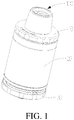
FIG. 1 is a schematic view of an atomizer according to a first embodiment; -
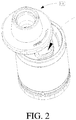
FIG. 2 is a schematic view of the atomizer of the first embodiment in a liquid injection state; -
FIG. 3 is a schematic view of an upper cover assembly inFIG. 1 ; -
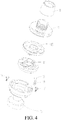
FIG. 4 is an exploded view of the upper cover assembly inFIG. 3 ; -
FIG. 5 is a schematic view of a connecting member inFIG. 4 ; -
FIG. 6 is a schematic view of a sealing member inFIG. 4 ; -
FIG. 7 is a schematic view of an inner lining member inFIG. 4 ; -
FIG. 8 is a schematic view of the inner lining member inFIG. 4 , viewed from another aspect; -
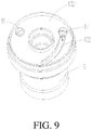
FIG. 9 is a schematic view showing the inner lining member and the connecting member when the atomizer is in a working state; -
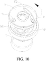
FIG. 10 is a schematic view showing the inner lining member and the connecting member when the atomizer is in a liquid injection state; -
FIG. 11 is a schematic view of an inner lining member according to a second embodiment; -
FIG. 12 is a schematic view showing the inner lining member and the connecting member when the atomizer of the second embodiment is in a working state; -
FIG. 13 is a schematic view showing the inner lining member and the connecting member when the inner lining member of the atomizer of the second embodiment is rotated; -
FIG. 14 is a schematic view showing the inner lining member and the connecting member when the atomizer of the second embodiment is in a liquid injection state. - Reference numerals of the components in the accompanying drawings are as follows.
atomizer 100upper cover assembly 10month piece 11upper cover 12inner lining member 13positioning hole 131first sliding groove 132translation groove 1321rotation groove 1322latching clip 133matching groove 134sealing member 14second liquid intake hole 141second sliding groove 142connecting member 15receiving portion 151first liquid intake hole 152latching groove 153mounting hole 154threaded hole 155rotating shaft 16limiting shaft 17elastic member 18limiting member 19sleeve pipe 20base assembly 30 - The present application is specifically illustrated with reference to the accompanying drawings. The accompanying drawings are simplified schematic views which shows fundamental structures of an exemplary embodiment of the present application. Thus, merely the constructions related to the present application are shown.
- As shown in
FIG. 1 andFIG. 2 , the present application provides an electronic cigarette (not shown). The electronic cigarette includes anatomizer 100 and a battery assembly (not shown) electrically connected to theatomizer 100. Theatomizer 100 includes anupper cover assembly 10, abase assembly 30, an atomizer head (not shown), and asleeve pipe 20. Theupper cover assembly 10 and thebase assembly 30 are respectively mounted on opposite ends of the atomizer head. Thesleeve pipe 20 is sleeved outside the atomizer head. - As shown in
FIG. 3 andFIG. 4 , theupper cover assembly 10 includes amouth piece 11, anupper cover 12, aninner lining member 13 and a connectingmember 15. Themouth piece 11 is detachably connected to theupper cover 12. Theupper cover 12 is connected to an upper end of theinner lining member 13. Theinner lining member 13 is rotatably connected to the connectingmember 15. - Both the
mouth piece 11 and theupper cover 12 substantially have a cylindrical structure with two opening ends. Theupper cover 12 is in communication with themouth piece 11. Themouth piece 11 is sleeved on the outside of theupper cover 12. - Referring to
FIG. 5 , the connectingmember 15 substantially has a cylindrical structure with two opening ends. The lower end of the connectingmember 15 is connected to the atomizer head. A liquid storage chamber (not shown) is formed between the connectingmember 15 and thesleeve pipe 20. The upper end surface of the connectingmember 15 is provided with a receivingportion 151. A sealingmember 14 having a shape matching the receivingportion 151 is positioned in the receivingportion 151. The sealingmember 14 can engage with the connectingmember 15 via an interference fit. The receivingportion 151 is provided with a firstliquid intake hole 152 at the bottom, and the firstliquid intake hole 152 is in communication with the liquid storage chamber. The side wall of the receivingportion 151 is provided with a latchinggroove 153. A rotatingshaft 16 and a limitingshaft 17 are provided on the upper end surface of the connectingmember 15. The upper end surface of the connectingmember 15 is further provided with a mountinghole 154. Anelastic member 18 is provided in the mountinghole 154, a limitingmember 19 is fixed to an upper end of theelastic member 18, and a part of the limitingmember 19 is exposed outside the mountinghole 154. In the illustrated embodiment, the limitingmember 19 can be a spherical member, such as a roll ball, for facilitating the limitingmember 19 to perform a movement in the mountinghole 154 with a small friction force. In the illustrated embodiment, both therotating shaft 16 and the limitingshaft 17 are screws, the connectingmember 15 is provided with a threadedhole 155 corresponding to each of therotating shaft 16 and the limitingshaft 17. - Referring to
FIG. 6 , the sealingmember 14 is provided with a secondliquid intake hole 141 corresponding to the firstliquid intake hole 152. The upper surface of the sealingmember 14 is provided with a second slidinggroove 142. The second slidinggroove 142 passes through a peripheral surface of the sealingmember 14, such that one end of the second slidinggroove 142 is in communication with the latchinggroove 153. In one embodiment, the sealingmember 14 is made of silica material. - Referring to
FIG. 7 andFIG. 8 , theinner lining member 13 substantially has a cylindrical structure with two opening ends. Theinner lining member 13 is provided with apositioning hole 131 corresponding to therotating shaft 16 and a first slidinggroove 132 corresponding to the limitingshaft 17. Both thepositioning hole 131 and the first slidinggroove 132 pass through opposite end surfaces of theinner lining member 13 along an axial direction of theinner lining member 13. Theinner lining member 13 is rotatably connected to therotating shaft 16, and the limitingshaft 17 can slide along the first slidinggroove 132. The lower end surface of theinner lining member 13 is provided with two matchinggrooves 134, and the positions of the two matchinggrooves 134 are respectively corresponding to the positions of theelastic member 18 when the firstliquid intake hole 152 is opened or closed. An edge of the lower end surface of theinner lining member 13 is provided with alatching clip 133. The latchingclip 133 can slide along the second slidinggroove 142 to enter the latchinggroove 153 located at one end of the second slidinggroove 142, thereby locking theinner lining member 13 to the connectingmember 15. - Referring to
FIG. 9 andFIG. 10 , when a liquid injection operation is performed, theupper cover 12 is rotated, to enable theupper cover 12 and theinner lining member 13 to rotate relative to the connectingmember 15 around a center of therotating shaft 16. The latchingclip 133 slides from the latchinggroove 153 into the second slidinggroove 142, thereby unlocking theinner lining member 13 and the connectingmember 15. During the rotation of theinner lining member 13, theelastic member 18 is compressed by theinner lining member 13 to improve a hand feeling, the limitingshaft 17 slides along the first slidinggroove 132, and at the same time, the latchingclip 133 slides along the second slidinggroove 142. When the firstliquid intake hole 152 and the secondliquid intake hole 141 are opened completely, theelastic member 18 is positioned in one of the matchinggrooves 134, in order to prevent theinner lining member 13 from rotating randomly to cover the secondliquid intake hole 141 and accordingly influence the liquid injection operation, such that it is convenient to perform the liquid injection operation. As the limitingmember 19 engages in one of the matchinggrooves 134, a vibration and a sound may send out, to remind the user that theinner lining member 13 has reached the right position. In the illustrated embodiment, theelastic member 18 can be members having elasticity restoring function, such as a spring or a rubber. - After the liquid injection is finished, the
upper cover 12 is rotated in a reversed direction, the latchingclip 133 enters the latchinggroove 153 by passing through the second slidinggroove 142, the latchingclip 133 locks theinner lining member 13 and the connectingmember 15, and theelastic member 18 engages in the other one of the matchinggrooves 134. - In the
atomizer 100, theupper cover 12 is pushed to slide from the lateral side, so that the secondliquid intake hole 141 is exposed for performing a liquid injection operation. The liquid injection operation is more convenient and easier. The rotatableinner lining member 13 is located inside theupper cover assembly 10, thereby ensuring an integrity of the outer appearance of the product. - The main differences between the second embodiment and the first embodiment are as follows. In the second embodiment, the first sliding
groove 132 and thepositioning hole 131 each have a shape different from that of the first embodiment. Meanwhile, in the second embodiment, the mountinghole 154, theelastic member 18 and theelastic member 19 in the connectingmember 15 are omitted, and the matchinggrooves 134 in the lower end surface of theinner lining member 13 are omitted. - Referring to
FIG. 11 , thepositioning hole 131 is a waist-shaped hole. - The first sliding
groove 132 is substantially L-shaped and includes atranslation groove 1321 and arotation groove 1322 in communication with thetranslation groove 1321. Thepositioning hole 131 is parallel to thetranslation groove 1321. - Referring to
FIG. 12 , when theinner lining member 13 and the connectingmember 15 are locked, the latchingclip 133 is engaged in the latchinggroove 153 of the connectingmember 15, the rotatingshaft 16 is positioned in one end of the translation hole 1311 away from the rotation hole 1312, and the limitingshaft 17 is positioned in one end of thetranslation groove 1321 away from therotation groove 1322. - Referring to
FIG. 12 andFIG. 13 , when a liquid injection operation is required, theupper cover 12 is pushed from the lateral side. The latchingclip 133 enters the second slidinggroove 142 from the latchinggroove 153, thereby unlocking theinner lining member 13 and the connectingmember 15. The rotatingshaft 16 moves from one end of thepositioning hole 131 to an opposite end of thepositioning hole 131, and the limitingshaft 17 moves from thetranslation groove 1321 to therotation groove 1322. Referring toFIG. 14 , theupper cover 12 is then rotated, such that theinner lining member 13 is rotated around an axis of therotating shaft 16. The latchingclip 133 slides along the second slidinggroove 142, and the limitingshaft 17 slides along therotation groove 1322 until the limitingshaft 17 reaches the end of therotation groove 1322 away from thetranslation groove 1321, such that the secondliquid intake hole 141 is exposed to perform a liquid injection. - After the liquid injection is finished, the
upper cover 12 is rotated in a reversed direction, causing thelatching clip 133 to slide along the second slidinggroove 142, and the limitingshaft 17 moves to thetranslation groove 1321. Then, theupper cover 12 is pushed to conduct a translational motion, causing thelatching clip 133 to enter the latchinggroove 153, thereby locking theinner lining member 13 and the connectingmember 15. - In the
atomizer 100, theupper cover 12 is firstly pushed and then caused to slide, such that the secondliquid intake hole 141 is exposed for performing a liquid injection operation. The liquid injection operation is simplified. A pushing operation is added prior to the sliding movement, such that the liquid intake hole cannot be opened easily by children, a children protection function is added. - The embodiments described above are merely preferred embodiments, but not intended to limit the present application. Any modifications, alternatives or improvements made within the principle of the present application should be interpreted as falling within the protection scope of the present application. The claims are not limited to the features or acts described above. Rather, the proper scope of the present application is defined by the appended claims.
Claims (20)
- An atomizer, comprising an upper cover assembly, a base assembly and an atomizer head, a liquid storage chamber being provided in the atomizer, wherein the upper cover assembly comprises an inner lining member and a connecting member, the connecting member is provided with a first liquid intake hole in communication with the liquid storage chamber, the inner lining member is provided with a positioning hole and a first sliding groove, the connecting member is provided with a rotating shaft mounted in the positioning hole and a limiting shaft mounted in the first limiting groove, the first sliding groove comprises a translation groove and a rotation groove in communication with the translation groove, the positioning hole is parallel to the translation groove, wherein the inner lining member or the connecting member is pushed until the limiting shaft slides from the translation groove into the rotation groove, the inner lining member and the connecting member are then rotated around the rotating shaft, the limiting shaft slides along the rotation groove to expose the first liquid intake hole.
- The atomizer according to claim 1, wherein the positioning hole is a waist-shaped hole, the first sliding groove is an L-shaped groove.
- The atomizer according to claim 1, wherein the connecting member is provided with a latching groove and the inner lining member is provided with a latching clip corresponding to the latching groove, or, the connecting member is provided with a latching clip and the inner lining member is provided with a latching groove corresponding to the latching clip; the latching clip is latched in the latching groove to cause the inner lining member to remain a closed state relative to the connecting member.
- The atomizer according to claim 3, wherein a sealing member is provided in the connecting member, the sealing member is provided with a second liquid intake hole corresponding to the first liquid intake hole.
- The atomizer according to claim 4, wherein the sealing member is provided with a second sliding groove for the latching clip to slide along.
- The atomizer according to claim 5, wherein the connecting member is provided with a receiving portion, the sealing member is hermetically positioned in the receiving portion.
- The atomizer according to claim 1, wherein the connecting member is provided with an elastic member, an end of the elastic member is fixed to the connecting member, an opposite end of the elastic member is provided with a limiting member, the inner lining member is provided with a matching groove corresponding to the limiting member.
- The atomizer according to claim 7, wherein the number of the matching groove is two, the positions of the two matching grooves are respectively corresponding to the positions of the limiting member when the first liquid intake hole is opened or closed.
- The atomizer according to claim 7, wherein the connecting member is provided with a mounting hole, the elastic member is positioned in the mounting hole, a part of the limiting member is exposed outside the mounting hole.
- An electronic cigarette, comprising an atomizer according to any of claims 1 to 9.
- An atomizer, comprising an upper cover assembly, a base assembly and an atomizer head, the upper cover assembly and the base assembly being respectively mounted on opposite ends of the atomizer head, a liquid storage chamber being provided in the atomizer, wherein the upper cover assembly comprises an inner lining member and a connecting member, the connecting member is provided with a first liquid intake hole in communication with the liquid storage chamber, the connecting member is provided with a rotating shaft and a limiting shaft, the inner lining member is provided with a first sliding groove, the limiting shaft extends through the first sliding groove, the inner lining member is rotatably connected to the rotating shaft, when the inner lining member is rotated relative to the connecting member, the limiting shaft slides along the first sliding groove so as to open or close the first liquid intake hole.
- The atomizer according to claim 11, wherein the connecting member is provided with a latching groove and the inner lining member is provided with a latching clip corresponding to the latching groove, or, the connecting member is provided with a latching clip and the inner lining member is provided with a latching groove corresponding to the latching clip; the latching clip is latched in the latching groove to cause the inner lining member to remain a closed state relative to the connecting member.
- The atomizer according to claim 12, wherein a sealing member is provided in the connecting member, the sealing member is provided with a second liquid intake hole corresponding to the first liquid intake hole.
- The atomizer according to claim 13, wherein the sealing member is provided with a second sliding groove for the latching clip to slide along.
- The atomizer according to claim 13, wherein the connecting member is provided with a receiving portion, the sealing member is hermetically positioned in the receiving portion.
- The atomizer according to claim 11, wherein the connecting member is provided with an elastic member, an end of the elastic member is fixed to the connecting member, an opposite end of the elastic member is provided with a limiting member, the inner lining member is provided with a matching groove corresponding to the limiting member.
- The atomizer according to claim 16, wherein the number of the matching groove is two, the positions of the two matching grooves are respectively corresponding to the positions of the limiting member when the first liquid intake hole is opened or closed.
- The atomizer according to claim 16, wherein the elastic member is a spring, the connecting member is provided with a mounting hole, the limiting member is a roll ball, the elastic member is positioned in the mounting hole, a part of the limiting member is exposed outside the mounting hole.
- The atomizer according to any of claims 11 to 18, wherein the upper cover assembly further comprises an upper cover, the upper cover is positioned on the inner lining member, the inner lining member is embedded in the upper cover.
- An electronic cigarette, comprising an atomizer according to any of claims 11 to 19.
Applications Claiming Priority (3)
| Application Number | Priority Date | Filing Date | Title |
|---|---|---|---|
| CN201720679809.0U CN207322682U (en) | 2017-06-12 | 2017-06-12 | Atomizer and its electronic cigarette |
| CN201720692045.9U CN207125316U (en) | 2017-06-12 | 2017-06-12 | Atomizer and its electronic cigarette |
| PCT/CN2018/087608 WO2018228132A1 (en) | 2017-06-12 | 2018-05-21 | Vaporizer and electronic cigarette using same |
Publications (2)
| Publication Number | Publication Date |
|---|---|
| EP3639682A1 true EP3639682A1 (en) | 2020-04-22 |
| EP3639682A4 EP3639682A4 (en) | 2021-03-03 |
Family
ID=64660111
Family Applications (1)
| Application Number | Title | Priority Date | Filing Date |
|---|---|---|---|
| EP18816898.3A Withdrawn EP3639682A4 (en) | 2017-06-12 | 2018-05-21 | Vaporizer and electronic cigarette using same |
Country Status (3)
| Country | Link |
|---|---|
| US (1) | US11304453B2 (en) |
| EP (1) | EP3639682A4 (en) |
| WO (1) | WO2018228132A1 (en) |
Cited By (1)
| Publication number | Priority date | Publication date | Assignee | Title |
|---|---|---|---|---|
| EP4026442A1 (en) * | 2021-01-11 | 2022-07-13 | JT International S.A. | Aerosol generation assembly and method for using such assembly |
Families Citing this family (5)
| Publication number | Priority date | Publication date | Assignee | Title |
|---|---|---|---|---|
| CN105919164B (en) * | 2016-06-23 | 2019-03-19 | 卓尔悦欧洲控股有限公司 | Atomising head, atomizer and electronic cigarette |
| USD948778S1 (en) * | 2019-08-24 | 2022-04-12 | Tuanfang Liu | Electronic cigarette |
| USD928397S1 (en) * | 2019-10-29 | 2021-08-17 | Shenzhen Smoore Technology Limited | Electronic atomizing device |
| USD948779S1 (en) * | 2019-11-28 | 2022-04-12 | Tuanfang Liu | Electronic cigarette atomizer |
| USD932097S1 (en) * | 2019-11-29 | 2021-09-28 | Tuanfang Liu | Electronic cigarette atomizer |
Family Cites Families (9)
| Publication number | Priority date | Publication date | Assignee | Title |
|---|---|---|---|---|
| US9901115B2 (en) * | 2013-08-30 | 2018-02-27 | Huizhou Kimree Technology Co., Ltd. Shenzhen Branch | Battery component and electronic cigarette |
| CN204146325U (en) * | 2014-08-12 | 2015-02-11 | 刘水根 | a tobacco evaporator |
| CN204949516U (en) * | 2015-06-05 | 2016-01-13 | 深圳市艾维普思科技股份有限公司 | Atomizer and electronic cigarette |
| CN204812051U (en) * | 2015-07-31 | 2015-12-02 | 深圳市欧比斯科技有限公司 | Electron smog spinning disk atomiser and electron cigarette thereof |
| CN205214210U (en) * | 2015-12-08 | 2016-05-11 | 深圳市赛尔美电子科技有限公司 | Atomizer |
| CN205284996U (en) * | 2015-12-09 | 2016-06-08 | 李述亨 | Sliding closure formula electron smog spinning disk atomiser |
| US10015992B2 (en) * | 2016-01-18 | 2018-07-10 | Shenzhen First Union Technology Co., Ltd. | Atomizer and electronic cigarette |
| CN207125316U (en) * | 2017-06-12 | 2018-03-23 | 常州市派腾电子技术服务有限公司 | Atomizer and its electronic cigarette |
| CN207322682U (en) * | 2017-06-12 | 2018-05-08 | 常州市派腾电子技术服务有限公司 | Atomizer and its electronic cigarette |
-
2018
- 2018-05-21 WO PCT/CN2018/087608 patent/WO2018228132A1/en not_active Ceased
- 2018-05-21 EP EP18816898.3A patent/EP3639682A4/en not_active Withdrawn
-
2019
- 2019-12-12 US US16/712,766 patent/US11304453B2/en active Active
Cited By (1)
| Publication number | Priority date | Publication date | Assignee | Title |
|---|---|---|---|---|
| EP4026442A1 (en) * | 2021-01-11 | 2022-07-13 | JT International S.A. | Aerosol generation assembly and method for using such assembly |
Also Published As
| Publication number | Publication date |
|---|---|
| WO2018228132A1 (en) | 2018-12-20 |
| US11304453B2 (en) | 2022-04-19 |
| EP3639682A4 (en) | 2021-03-03 |
| US20200113236A1 (en) | 2020-04-16 |
Similar Documents
| Publication | Publication Date | Title |
|---|---|---|
| EP3639682A1 (en) | Vaporizer and electronic cigarette using same | |
| JP6714155B2 (en) | Sliding lid opening device | |
| US8910783B2 (en) | Electronic cigarette case | |
| CN106557121B (en) | Portable electronic device | |
| EP3103356A1 (en) | Atomizer and electronic cigarette thereof | |
| US20140084770A1 (en) | Door assembly | |
| WO2016202303A1 (en) | Atomiser and aerosol generating apparatus | |
| US10280662B2 (en) | Safety door lock using door handle | |
| CA2899528A1 (en) | Electronic cigarette case | |
| CN207476956U (en) | It can oiling atomizer and electronic cigarette | |
| CN109588040B (en) | Liquid injection protection devices, atomizers and electronic cigarettes | |
| CN105737489A (en) | Side-by-side combination refrigerator with turnover beam | |
| JP2014218258A5 (en) | ||
| CN112841738B (en) | Atomization component and electronic atomization device | |
| TWM546226U (en) | Portable sprayer with dustproof device | |
| CN105342182A (en) | Anti-pinch drawer | |
| CN112335944A (en) | Aerosol generator | |
| US7380314B2 (en) | Hinge and mobile phone with the hinge | |
| CN217826790U (en) | Press rotary type aerial fog generating device | |
| CN207125316U (en) | Atomizer and its electronic cigarette | |
| CN207322682U (en) | Atomizer and its electronic cigarette | |
| CN211794322U (en) | Switching device and electronic cigarette | |
| EP3718425B1 (en) | Atomizer and electronic cigarette | |
| CN111406996A (en) | Electronic cigarette | |
| CN219781547U (en) | Atomizer and aerosol generating device using the same |
Legal Events
| Date | Code | Title | Description |
|---|---|---|---|
| STAA | Information on the status of an ep patent application or granted ep patent |
Free format text: STATUS: THE INTERNATIONAL PUBLICATION HAS BEEN MADE |
|
| PUAI | Public reference made under article 153(3) epc to a published international application that has entered the european phase |
Free format text: ORIGINAL CODE: 0009012 |
|
| STAA | Information on the status of an ep patent application or granted ep patent |
Free format text: STATUS: REQUEST FOR EXAMINATION WAS MADE |
|
| 17P | Request for examination filed |
Effective date: 20200108 |
|
| AK | Designated contracting states |
Kind code of ref document: A1 Designated state(s): AL AT BE BG CH CY CZ DE DK EE ES FI FR GB GR HR HU IE IS IT LI LT LU LV MC MK MT NL NO PL PT RO RS SE SI SK SM TR |
|
| AX | Request for extension of the european patent |
Extension state: BA ME |
|
| DAV | Request for validation of the european patent (deleted) | ||
| DAX | Request for extension of the european patent (deleted) | ||
| A4 | Supplementary search report drawn up and despatched |
Effective date: 20210201 |
|
| RIC1 | Information provided on ipc code assigned before grant |
Ipc: A24F 40/49 20200101ALI20210126BHEP Ipc: A24F 47/00 20200101AFI20210126BHEP |
|
| STAA | Information on the status of an ep patent application or granted ep patent |
Free format text: STATUS: EXAMINATION IS IN PROGRESS |
|
| 17Q | First examination report despatched |
Effective date: 20230208 |
|
| STAA | Information on the status of an ep patent application or granted ep patent |
Free format text: STATUS: THE APPLICATION IS DEEMED TO BE WITHDRAWN |
|
| 18D | Application deemed to be withdrawn |
Effective date: 20230620 |