EP3639648B1 - Sorting table for a fruit harvester - Google Patents
Sorting table for a fruit harvester Download PDFInfo
- Publication number
- EP3639648B1 EP3639648B1 EP18315033.3A EP18315033A EP3639648B1 EP 3639648 B1 EP3639648 B1 EP 3639648B1 EP 18315033 A EP18315033 A EP 18315033A EP 3639648 B1 EP3639648 B1 EP 3639648B1
- Authority
- EP
- European Patent Office
- Prior art keywords
- sorting
- combs
- rollers
- sorting table
- roller
- Prior art date
- Legal status (The legal status is an assumption and is not a legal conclusion. Google has not performed a legal analysis and makes no representation as to the accuracy of the status listed.)
- Active
Links
Images




Classifications
-
- A—HUMAN NECESSITIES
- A01—AGRICULTURE; FORESTRY; ANIMAL HUSBANDRY; HUNTING; TRAPPING; FISHING
- A01D—HARVESTING; MOWING
- A01D46/00—Picking of fruits, vegetables, hops, or the like; Devices for shaking trees or shrubs
- A01D46/28—Vintaging machines, i.e. grape harvesting machines
- A01D46/285—Vintaging machines, i.e. grape harvesting machines with means for separating leaves and grapes, e.g. pneumatical means like blowing or aspirating devices
-
- B—PERFORMING OPERATIONS; TRANSPORTING
- B07—SEPARATING SOLIDS FROM SOLIDS; SORTING
- B07B—SEPARATING SOLIDS FROM SOLIDS BY SIEVING, SCREENING, SIFTING OR BY USING GAS CURRENTS; SEPARATING BY OTHER DRY METHODS APPLICABLE TO BULK MATERIAL, e.g. LOOSE ARTICLES FIT TO BE HANDLED LIKE BULK MATERIAL
- B07B1/00—Sieving, screening, sifting, or sorting solid materials using networks, gratings, grids, or the like
- B07B1/12—Apparatus having only parallel elements
- B07B1/14—Roller screens
- B07B1/15—Roller screens using corrugated, grooved or ribbed rollers
-
- B—PERFORMING OPERATIONS; TRANSPORTING
- B07—SEPARATING SOLIDS FROM SOLIDS; SORTING
- B07B—SEPARATING SOLIDS FROM SOLIDS BY SIEVING, SCREENING, SIFTING OR BY USING GAS CURRENTS; SEPARATING BY OTHER DRY METHODS APPLICABLE TO BULK MATERIAL, e.g. LOOSE ARTICLES FIT TO BE HANDLED LIKE BULK MATERIAL
- B07B1/00—Sieving, screening, sifting, or sorting solid materials using networks, gratings, grids, or the like
- B07B1/46—Constructional details of screens in general; Cleaning or heating of screens
- B07B1/4609—Constructional details of screens in general; Cleaning or heating of screens constructional details of screening surfaces or meshes
- B07B1/4636—Regulation of screen apertures
Definitions
- the present invention relates to a harvester for harvesting fruit, such as grapes and other berries, and, more specifically to sorting arrangements used in such harvesters.
- a fruit harvester in the form of a self-propelled grape harvester includes a chassis which carries an onboard power plant and several onboard sub-systems for processing the grapes.
- the grape harvester straddles and traverses along at least one row of grape vines, and a picking system separates the grapes and Material Other than Grapes (referred to as "MOG", such as leaves, stems, wood debris, etc.) from the vines.
- the picking system typically is in the form of "pivotal strikers" or “trunk shakers”.
- the pivotal strikers can include a double bank of flexible horizontal rods that strike and shake the vine to remove the fruit.
- the trunk shakers can include parallel skiis oriented on edge that move from side to side to impart horizontal vibration to the vines for removal of the grapes and MOG.
- a conveying system transports the grapes and MOG to a cleaning system, which in turn separates the grapes from the MOG and cleans the crop.
- the cleaning system can include one or more cleaning fans, a sorting table, and a destemmer.
- the one or more cleaning fans can be positioned upstream in the cleaning system, and remove larger MOG, such as leaves, from the stream of crop material by suction and discharge the larger MOG, such as behind the harvester.
- the sorting table can include a combination of conveying rollers and sorting rollers, which can be optimized for different sizes of grapes. The grapes which are dropped on the conveying rollers are transported to the sorting rollers, where the grapes are sorted from the MOG.
- the sorting rollers can be configured with an adjustable gap between the sorting rollers such that the grapes fall through and the MOG is transported to the end of the sorting table and discharged.
- the rollers may also receive grapes in bunches and convey these rearwardly to a destemmer.
- the destemmer removes the central stalk or stems from the grapes, which are received below the destemmer.
- the central stalk is ejected at the end of the destemmer.
- PCT publication WO2012/150354 discloses a sorting table that can be used in a grape harvester.
- the Braud 9090X grape harvester which is sold by the assignee of the present invention, can utilize such a sorting table.
- the sorting table includes a frame carrying a plurality of sorting rollers positioned downstream from a plurality of conveying rollers. Grape bunches and loose grapes including MOG are deposited on the conveying rollers and the MOG is sorted from the loose grapes using the sorting rollers.
- EP 3006120 B1 discloses a stationary sorting table which can be used in the winery for sorting grapes from MOG after the harvest, which is required when the grape harvester itself was not provided with an effective sorting system.
- the spacing between the downstream sorting rollers can be manually adjusted using a manual crank or handle (Fig. 1B) which selectively raises and lowers a pair of combs positioned along the sides of the sorting table.
- Fig. 1B selectively raises and lowers a pair of combs positioned along the sides of the sorting table.
- Each comb has a number of slots formed between adjacent teeth, and each sorting roller is associated with a respective pair of slots in the opposite combs.
- the slots extend at increasing angles from the front to the rear end of the sorting table.
- the combs are spring biased relative to the sorting rollers, and a cam arrangement can be manually adjusted to overcome the spring bias. Manually raising and lowering the combs in turn increases or decreases the spacing between adjacent rows of sorting roller
- an exemplary embodiment is directed to a sorting table for sorting fruit in a fruit harvester.
- the sorting table includes a frame with a first side member and a second side member, a plurality of conveying rollers carried by the frame, a plurality of sorting rollers carried by the frame and positioned downstream from the conveying rollers, and a pair of combs positioned in association with the first side member or the second side member.
- Each comb includes a plurality of slots with each of the slots being associated with a respective one of the plurality of sorting rollers.
- the sorting table is characterized in that each of the combs is pivotally coupled with the corresponding first side member or the second side member.
- An actuator is coupled with each of the combs for selectively moving the pair of combs in directions transverse to the crop flow direction.
- An electrical processing circuit coupled with the actuator is configured for controlling the actuator and thereby selectively increasing or decreasing a spacing between the sorting rollers.
- the plurality of slots have distinct rearward inclinations, with the rearward inclinations decreasing for slots closer to the pivot point of the combs.
- the plurality of sorting rollers has an upstream end that is positioned adjacent to a downstream end of the plurality of conveying rollers, and the upstream end of the sorting rollers is connected to the downstream end of the conveying rollers and maintained by this connection at a fixed distance therefrom.
- an upstream sorting roller positioned at the upstream end of the plurality of sorting rollers is mechanically connected with a downstream conveying roller positioned at a downstream end of the plurality of conveying rollers, thereby maintaining a substantially constant spacing between the upstream sorting roller and the downstream conveying roller.
- the upstream sorting roller is connected to the downstream conveying roller by a pair of mechanical links, each of the links being positioned at and connected with a respective opposite end of the upstream sorting roller and the downstream conveying roller.
- the conveying rollers are carried by guide surfaces provided on the first and second side frame members, allowing for the movement of the conveying rollers in a fore-and-aft direction with respect to the frame.
- a distance member maintains the spacing between the conveying rollers during the fore-and-aft movement.
- the distance member includes at least one front comb positioned in association with the first side member or the second side member.
- Each comb includes a plurality of slots with each of the slots being associated with a respective one of the plurality of conveying rollers.
- the invention in another embodiment includes an elongate member connected at opposite ends with a respective one of the combs.
- the actuator is coupled with the elongate member to simultaneously move the pair of combs in the selected transverse direction.
- the actuator comprises a powered ram connected with the elongate member, and the electrical processing circuit is configured to selectively extend and retract the ram to thereby simultaneously move the pair of combs in the selected transverse direction.
- a lever arm is connected with and extends from the elongate member.
- the lever arm is pivotable about an axis of the elongate member, and the ram of the actuator is connected with the lever arm to pivot and thereby simultaneously move the pair of combs in the selected transverse direction.
- a pair of swing arms are connected with and extend from the elongate member. Each of the swing arms engage a corresponding one of the combs.
- each of the combs comprises a slot
- each of the swing arms comprises a distal end carrying a roller which is positioned within a corresponding one of the slots.
- each of the combs has a trailing end which is pivotally coupled with a corresponding one of the first side member or the second side member.
- a grape harvester comprises a sorting table, according to any of the sub-claims.
- a method of sorting fruit utilizes a sorting table, according to any of the sub-claims.
- a portion of a fruit harvester 10 in the form of a grape harvester can be variously configured for different applications.
- the fruit harvester 10 can include a chassis 12 carrying multiple different sub-systems and components, such as an operator cab and a picking system (not shown in Fig. 1 ), and a cleaning system 14.
- the cleaning system 14 can include a cleaning fan (not shown in Fig. 1 ), a destemmer 16, and a sorting table 18.
- the destemmer 16 is used to remove the central stalk or stems from the bunches of grapes.
- the bunches are received on an endless conveyor having a mesh surface (not shown), which allows the passage of loose grapes to the sorting table 18.
- the conveyor surface feeds any bunches and MOG greater than the mesh apertures rearwardly and upwardly to a series of transverse rotating shafts. These shafts have plastic radial fingers which pass close to the mesh surface and interact with the bunches to detach the grapes from the central stems.
- the loosened grapes fall through the mesh surface to the bottom of the destemmer housing, which guides them to the sorting table 18.
- the stems and the MOG remain on top of the mesh conveyor until they are ejected at the rear end of the destemmer housing.
- the sorting table 18 generally includes a frame 20, a plurality of conveying rollers 22, and a plurality of sorting rollers 24.
- the conveying rollers 24 receive grapes and MOG and transport the grapes and MOG downstream (relative to a crop travel direction 26) to the sorting rollers 24 for sorting the MOG from the grapes.
- the frame 20 includes a first side member 28 and a second side member 30.
- the plurality of conveying rollers 22 are carried by the frame 20, more specifically by the respective side frame members 28 and 30.
- the plurality of sorting rollers 24 are likewise carried by the frame 20, more specifically by the respective side frame members 28 and 30.
- the surfaces of the conveying rollers 24 may be smooth or profiled, but the clearance between them does not allow for the passage of the loose berries.
- Each of the sorting rollers 24 includes a central shaft 32 carrying a succession of toothed disks or wheels 34 between cylindrical spacers. However, it is also conceivable to provide the central shaft 32 with another, e.g. wavy profile, resulting in a plurality of passages for the berries between successive sorting rollers.
- the sorting rollers 24 have bearings 36 at the outboards ends of the central shaft 32.
- the bearings 36 are mounted on guide surfaces of the side frame members 28, 30, allowing for fore-and-aft movement of the sorting rollers 24 in a horizontal plane, substantially parallel to the side frame members 28, 30.
- a pair of combs 38 is positioned at opposite ends of the sorting rollers 24, with one comb 38 being positioned adjacent to the first side member 28 and the other comb 38 being positioned adjacent to the second side member 30.
- Each comb 38 includes a plurality of slots 40 with each of the slots 40 being associated with a respective one of the plurality of sorting rollers 24.
- Each of the combs 38 is pivotally coupled with a corresponding first side member 28 or second side member 30.
- each of the combs 38 has a trailing end 42 (relative to the direction of crop travel 26) which is pivotally coupled with a corresponding first side member 28 or second side member 30.
- each comb 38 could be pivotally coupled at a different location, such as the leading end or approximate middle of the comb 38.
- An actuator 44 is coupled with each of the combs 38 for selectively moving the pair of combs 38 in directions transverse to the crop flow direction.
- the actuator 44 can be configured as different types of an actuator, depending on the specific application.
- the actuator 44 can be configured as a fluid powered cylinder and piston arrangement, or a screw arrangement driven by an electric motor.
- the actuator 44 is configured as a powered ram which is connected with a transversely arranged elongate member 46.
- the elongate member 46 is connected at opposite ends with a respective one of the combs 38, and the actuator 44 is coupled with the elongate member to simultaneously move the pair of combs in the selected transverse direction.
- a lever arm 48 can be connected with and extend from the elongate member 46.
- the lever arm 48 is pivotable about an axis (not numbered) of the elongate member 46, and the ram 44 can be connected with the lever arm 48 to pivot and thereby simultaneously move the pair of combs 38 in the selected transverse direction.
- a pair of swing arms 50 can be connected with and extend from the outboard ends of the elongate member 46, with each of the swing arms 50 engaging a corresponding one of the combs 38.
- Each of the swing arms 50 can include a distal end (not numbered) carrying a roller 52 which is positioned within a corresponding slot 54 formed in the combs 38.
- an electrical processing circuit 56 can be coupled with the actuator 44, such as by a wired or wireless connection, LAN, etc.
- the electrical processing circuit 56 can be digital and/or analog, and can be placed at a suitable location on the fruit harvester 10, such as in an operator cab 58.
- the electrical processing circuit 56 can include any number of discrete components, such as a static and/or dynamic memory 60, input device (not specifically shown, etc.).
- the electrical processing circuit 56 can be configured for controlling the actuator 44 and thereby selectively increasing or decreasing a spacing between the sorting rollers 24.
- the electrical processing circuit 56 can be configured to selectively extend and retract the ram of the actuator 44 to thereby simultaneously move the pair of combs 38 in the selected transverse direction.
- the slots 40 are not parallel and have a rearward inclination that decreases for slots 40 closer to the pivot point of the combs 38.
- the last slot 40 is taking a substantially vertical position.
- the sorting table 18 is configured such that the spacing between the last conveying roller 22 and the first sorting roller 24 remains substantially constant, regardless of the adjustment and spacing between the sorting rollers 24.
- the plurality of sorting rollers 24 has an upstream end 62 which is positioned adjacent to and linked with a downstream end 64 of the plurality of conveying rollers 22.
- an upstream sorting roller 66 positioned at the upstream end 62 of the plurality of sorting rollers 24 is mechanically connected with a downstream conveying roller 68 positioned at the downstream end 64 of the plurality of conveying rollers 22, thereby maintaining a substantially constant spacing between the upstream sorting roller 66 and the downstream conveying roller 68.
- the upstream sorting roller 66 can be mechanically connected with the downstream conveying roller via at least one mechanical link 70, such as a pair of mechanical links which are positioned at and connected with bearings at a respective opposite end of the upstream sorting roller 66 and bearings at the downstream conveying roller 68.
- the conveying rollers 22 are mounted for fore-and-aft movement relative to the frame 20.
- the outer ends of the conveying rollers 22 are received in bearings which are carried by guide surfaces of the side frame members 28, 30, which may be aligned with the guide surfaces for the sorting rollers 24.
- the bearings are separated by the teeth of further combs 80 that are provided adjacent the first and second side frame members 28, 30.
- Each comb 80 is provided with fore-and-aft extending slots 82 for receiving a pin or bolt 84 that is affixed to the adjacent frame member 28, 30.
- Movement of the combs 80 over their respective bolts 84 results in a synchronized movement of all conveying rollers 22 in the same horizontal plane, in which the sorting rollers 24 can move. Meanwhile the teeth of the combs 80 ensure that the spacing between the conveying rollers 22 does not change. This may result in a variation of the distance between the upstream conveying roller 22 and the frame 20 as can be seen in Figures 5 and 6 . The occurrence of a wider gap in this area does not have to affect the operation of the cleaning system 14 if no berries and MOG are fed to this particular section.
- a motor and chain drive arrangement 72 simultaneously drives the conveying rollers 22 and sorting rollers 24 at a selected rotational operating speed.
- the chain drivingly meshes with sprockets arranged on the corresponding ends of the rollers 24, 24.
- An operator can input a desired spacing between the sorting rollers 24 using any suitable input device, such as a keyboard, touch screen, etc.
- the electrical processing circuit 56 receives the desired spacing and controls the actuator 44 accordingly to pivot the combs 38 and effect the spacing between the sorting rollers 24.
- the distance between the upstream sorting roller 66 and downstream conveying roller 68 remains substantially constant because of the interlink using the mechanical link 70.
- the ends of the downstream conveying roller 68 pull along the combs 80 and the ends of the other conveying rollers 22.
Landscapes
- Life Sciences & Earth Sciences (AREA)
- Environmental Sciences (AREA)
- Sorting Of Articles (AREA)
Description
- The present invention relates to a harvester for harvesting fruit, such as grapes and other berries, and, more specifically to sorting arrangements used in such harvesters.
- A fruit harvester in the form of a self-propelled grape harvester includes a chassis which carries an onboard power plant and several onboard sub-systems for processing the grapes. The grape harvester straddles and traverses along at least one row of grape vines, and a picking system separates the grapes and Material Other than Grapes (referred to as "MOG", such as leaves, stems, wood debris, etc.) from the vines. The picking system typically is in the form of "pivotal strikers" or "trunk shakers". The pivotal strikers can include a double bank of flexible horizontal rods that strike and shake the vine to remove the fruit. The trunk shakers can include parallel skiis oriented on edge that move from side to side to impart horizontal vibration to the vines for removal of the grapes and MOG.
- A conveying system transports the grapes and MOG to a cleaning system, which in turn separates the grapes from the MOG and cleans the crop. The cleaning system can include one or more cleaning fans, a sorting table, and a destemmer. The one or more cleaning fans can be positioned upstream in the cleaning system, and remove larger MOG, such as leaves, from the stream of crop material by suction and discharge the larger MOG, such as behind the harvester. The sorting table can include a combination of conveying rollers and sorting rollers, which can be optimized for different sizes of grapes. The grapes which are dropped on the conveying rollers are transported to the sorting rollers, where the grapes are sorted from the MOG. The sorting rollers can be configured with an adjustable gap between the sorting rollers such that the grapes fall through and the MOG is transported to the end of the sorting table and discharged. The rollers may also receive grapes in bunches and convey these rearwardly to a destemmer. The destemmer removes the central stalk or stems from the grapes, which are received below the destemmer. The central stalk is ejected at the end of the destemmer.
-
PCT publication WO2012/150354 (equivalentUS Patent No. 9,265,279 -
EP 3006120 B1 discloses a stationary sorting table which can be used in the winery for sorting grapes from MOG after the harvest, which is required when the grape harvester itself was not provided with an effective sorting system. The spacing between the downstream sorting rollers can be manually adjusted using a manual crank or handle (Fig. 1B) which selectively raises and lowers a pair of combs positioned along the sides of the sorting table. Each comb has a number of slots formed between adjacent teeth, and each sorting roller is associated with a respective pair of slots in the opposite combs. The slots extend at increasing angles from the front to the rear end of the sorting table. The combs are spring biased relative to the sorting rollers, and a cam arrangement can be manually adjusted to overcome the spring bias. Manually raising and lowering the combs in turn increases or decreases the spacing between adjacent rows of sorting rollers. - In accordance with an aspect of the invention, an exemplary embodiment is directed to a sorting table for sorting fruit in a fruit harvester. The sorting table includes a frame with a first side member and a second side member, a plurality of conveying rollers carried by the frame, a plurality of sorting rollers carried by the frame and positioned downstream from the conveying rollers, and a pair of combs positioned in association with the first side member or the second side member. Each comb includes a plurality of slots with each of the slots being associated with a respective one of the plurality of sorting rollers. The sorting table is characterized in that each of the combs is pivotally coupled with the corresponding first side member or the second side member. An actuator is coupled with each of the combs for selectively moving the pair of combs in directions transverse to the crop flow direction. An electrical processing circuit coupled with the actuator is configured for controlling the actuator and thereby selectively increasing or decreasing a spacing between the sorting rollers.
- In another embodiment of the invention, the plurality of slots have distinct rearward inclinations, with the rearward inclinations decreasing for slots closer to the pivot point of the combs.
- In yet another embodiment of the invention, the plurality of sorting rollers has an upstream end that is positioned adjacent to a downstream end of the plurality of conveying rollers, and the upstream end of the sorting rollers is connected to the downstream end of the conveying rollers and maintained by this connection at a fixed distance therefrom.
- In yet another embodiment of the invention, an upstream sorting roller positioned at the upstream end of the plurality of sorting rollers is mechanically connected with a downstream conveying roller positioned at a downstream end of the plurality of conveying rollers, thereby maintaining a substantially constant spacing between the upstream sorting roller and the downstream conveying roller.
- In yet another embodiment of the invention, the upstream sorting roller is connected to the downstream conveying roller by a pair of mechanical links, each of the links being positioned at and connected with a respective opposite end of the upstream sorting roller and the downstream conveying roller.
- In yet another embodiment of the invention, the conveying rollers are carried by guide surfaces provided on the first and second side frame members, allowing for the movement of the conveying rollers in a fore-and-aft direction with respect to the frame.
- In yet another embodiment of the invention, a distance member maintains the spacing between the conveying rollers during the fore-and-aft movement.
- In a yet another embodiment of the invention, the distance member includes at least one front comb positioned in association with the first side member or the second side member. Each comb includes a plurality of slots with each of the slots being associated with a respective one of the plurality of conveying rollers.
- The invention in another embodiment includes an elongate member connected at opposite ends with a respective one of the combs. The actuator is coupled with the elongate member to simultaneously move the pair of combs in the selected transverse direction.
- In yet another embodiment of the invention, the actuator comprises a powered ram connected with the elongate member, and the electrical processing circuit is configured to selectively extend and retract the ram to thereby simultaneously move the pair of combs in the selected transverse direction.
- In yet another embodiment of the invention, a lever arm is connected with and extends from the elongate member. The lever arm is pivotable about an axis of the elongate member, and the ram of the actuator is connected with the lever arm to pivot and thereby simultaneously move the pair of combs in the selected transverse direction.
- In yet another embodiment of the invention, a pair of swing arms are connected with and extend from the elongate member. Each of the swing arms engage a corresponding one of the combs.
- In yet another embodiment of the invention, each of the combs comprises a slot, and each of the swing arms comprises a distal end carrying a roller which is positioned within a corresponding one of the slots.
- In yet another embodiment of the invention, each of the combs has a trailing end which is pivotally coupled with a corresponding one of the first side member or the second side member.
- In yet another embodiment of the invention, a grape harvester comprises a sorting table, according to any of the sub-claims.
- In accordance with another aspect of the invention, a method of sorting fruit utilizes a sorting table, according to any of the sub-claims.
- The above-mentioned and other features and advantages of this invention, and the manner of attaining them, will become more apparent and the invention will be better understood by reference to the following description of embodiments of the invention taken in conjunction with the accompanying drawings, wherein:
-
Fig. 1 is a perspective view of a side portion of a fruit harvester which can include a sorting table according to an embodiment of the present invention; -
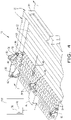
Fig. 2 is a perspective view of an embodiment of a sorting table of the present invention; -
Fig. 3 is another perspective view of the sorting table shown inFig. 2 , with the cover and actuator removed; -
Fig. 4 is a perspective view of a portion of the sorting table shown inFigs. 2 and3 , with the actuator coupled with an electrical processing circuit; -
Fig. 5 is a side view of the sorting table shown inFigs. 2-4 , with the combs in a raised position; -
Fig. 6 is a side view of the sorting table shown inFigs. 2-5 , with the combs in a lowered position; -
Fig. 7 is a side sectional view taken along line 7-7 inFig. 4 ; and -
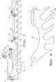
Fig. 8 is a side view of one of the combs. - Corresponding reference characters indicate corresponding parts throughout the several views. The exemplifications set out herein illustrate embodiments of the invention, and such exemplifications are not to be construed as limiting the scope of the invention in any manner.
- Referring now to the drawings, and more particularly to
Fig. 1 , there is shown a portion of afruit harvester 10 in the form of a grape harvester. Thefruit harvester 10 can be variously configured for different applications. Thefruit harvester 10 can include achassis 12 carrying multiple different sub-systems and components, such as an operator cab and a picking system (not shown inFig. 1 ), and acleaning system 14. - The
cleaning system 14 can include a cleaning fan (not shown inFig. 1 ), adestemmer 16, and a sorting table 18. Thedestemmer 16 is used to remove the central stalk or stems from the bunches of grapes. Typically the bunches are received on an endless conveyor having a mesh surface (not shown), which allows the passage of loose grapes to the sorting table 18. The conveyor surface feeds any bunches and MOG greater than the mesh apertures rearwardly and upwardly to a series of transverse rotating shafts. These shafts have plastic radial fingers which pass close to the mesh surface and interact with the bunches to detach the grapes from the central stems. The loosened grapes fall through the mesh surface to the bottom of the destemmer housing, which guides them to the sorting table 18. The stems and the MOG remain on top of the mesh conveyor until they are ejected at the rear end of the destemmer housing. - Referring now to
Figs. 2-8 , the sorting table 18 is shown and will be described in greater detail. The sorting table 18 generally includes aframe 20, a plurality of conveyingrollers 22, and a plurality of sortingrollers 24. The conveyingrollers 24 receive grapes and MOG and transport the grapes and MOG downstream (relative to a crop travel direction 26) to the sortingrollers 24 for sorting the MOG from the grapes. Theframe 20 includes afirst side member 28 and asecond side member 30. The plurality of conveyingrollers 22 are carried by theframe 20, more specifically by the respectiveside frame members rollers 24 are likewise carried by theframe 20, more specifically by the respectiveside frame members rollers 24 may be smooth or profiled, but the clearance between them does not allow for the passage of the loose berries. Each of the sortingrollers 24 includes acentral shaft 32 carrying a succession of toothed disks orwheels 34 between cylindrical spacers. However, it is also conceivable to provide thecentral shaft 32 with another, e.g. wavy profile, resulting in a plurality of passages for the berries between successive sorting rollers. The sortingrollers 24 havebearings 36 at the outboards ends of thecentral shaft 32. Thebearings 36 are mounted on guide surfaces of theside frame members rollers 24 in a horizontal plane, substantially parallel to theside frame members - A pair of
combs 38 is positioned at opposite ends of the sortingrollers 24, with onecomb 38 being positioned adjacent to thefirst side member 28 and theother comb 38 being positioned adjacent to thesecond side member 30. Eachcomb 38 includes a plurality ofslots 40 with each of theslots 40 being associated with a respective one of the plurality of sortingrollers 24. Each of thecombs 38 is pivotally coupled with a correspondingfirst side member 28 orsecond side member 30. In the illustrated embodiment, each of thecombs 38 has a trailing end 42 (relative to the direction of crop travel 26) which is pivotally coupled with a correspondingfirst side member 28 orsecond side member 30. However, eachcomb 38 could be pivotally coupled at a different location, such as the leading end or approximate middle of thecomb 38. - An
actuator 44 is coupled with each of thecombs 38 for selectively moving the pair ofcombs 38 in directions transverse to the crop flow direction. Theactuator 44 can be configured as different types of an actuator, depending on the specific application. For example, theactuator 44 can be configured as a fluid powered cylinder and piston arrangement, or a screw arrangement driven by an electric motor. - In the embodiment shown, the
actuator 44 is configured as a powered ram which is connected with a transversely arrangedelongate member 46. Theelongate member 46 is connected at opposite ends with a respective one of thecombs 38, and theactuator 44 is coupled with the elongate member to simultaneously move the pair of combs in the selected transverse direction. To that end, alever arm 48 can be connected with and extend from theelongate member 46. Thelever arm 48 is pivotable about an axis (not numbered) of theelongate member 46, and theram 44 can be connected with thelever arm 48 to pivot and thereby simultaneously move the pair ofcombs 38 in the selected transverse direction. A pair ofswing arms 50 can be connected with and extend from the outboard ends of theelongate member 46, with each of theswing arms 50 engaging a corresponding one of thecombs 38. Each of theswing arms 50 can include a distal end (not numbered) carrying aroller 52 which is positioned within a correspondingslot 54 formed in thecombs 38. - Referring now more specifically to
Fig. 4 , anelectrical processing circuit 56 can be coupled with theactuator 44, such as by a wired or wireless connection, LAN, etc. Theelectrical processing circuit 56 can be digital and/or analog, and can be placed at a suitable location on thefruit harvester 10, such as in anoperator cab 58. Theelectrical processing circuit 56 can include any number of discrete components, such as a static and/ordynamic memory 60, input device (not specifically shown, etc.). Theelectrical processing circuit 56 can be configured for controlling theactuator 44 and thereby selectively increasing or decreasing a spacing between the sortingrollers 24. For example, in the embodiment shown, theelectrical processing circuit 56 can be configured to selectively extend and retract the ram of theactuator 44 to thereby simultaneously move the pair ofcombs 38 in the selected transverse direction. It can be understood by reference toFigs. 7 and 8 that theslots 40 are not parallel and have a rearward inclination that decreases forslots 40 closer to the pivot point of thecombs 38. In the present embodiment thelast slot 40 is taking a substantially vertical position. When thecombs 38 are moved in a direction away from the sortingrollers 24, then the sections of theslots 40 that hold theroller bearings 36 diverge away from each other and cause the spacing between the sortingrollers 24 to increase. On the other hand, when thecombs 38 are moved in a direction toward the sortingrollers 24, then the sections of theslots 40 holding thebearings 36 converge toward each other and the spacing between the sortingrollers 24 decreases. - According to another aspect of the present invention, the sorting table 18 is configured such that the spacing between the last conveying
roller 22 and thefirst sorting roller 24 remains substantially constant, regardless of the adjustment and spacing between the sortingrollers 24. - More particularly, the plurality of sorting
rollers 24 has anupstream end 62 which is positioned adjacent to and linked with adownstream end 64 of the plurality of conveyingrollers 22. In the illustrated embodiment, anupstream sorting roller 66 positioned at theupstream end 62 of the plurality of sortingrollers 24 is mechanically connected with a downstream conveyingroller 68 positioned at thedownstream end 64 of the plurality of conveyingrollers 22, thereby maintaining a substantially constant spacing between theupstream sorting roller 66 and the downstream conveyingroller 68. In one embodiment, theupstream sorting roller 66 can be mechanically connected with the downstream conveying roller via at least onemechanical link 70, such as a pair of mechanical links which are positioned at and connected with bearings at a respective opposite end of theupstream sorting roller 66 and bearings at the downstream conveyingroller 68. - In the illustrated embodiment, also the conveying
rollers 22 are mounted for fore-and-aft movement relative to theframe 20. The outer ends of the conveyingrollers 22 are received in bearings which are carried by guide surfaces of theside frame members rollers 24. In order to maintain the spacing between the surfaces of the conveyingrollers 22, the bearings are separated by the teeth offurther combs 80 that are provided adjacent the first and secondside frame members comb 80 is provided with fore-and-aft extending slots 82 for receiving a pin or bolt 84 that is affixed to theadjacent frame member combs 80 over theirrespective bolts 84 results in a synchronized movement of all conveyingrollers 22 in the same horizontal plane, in which the sortingrollers 24 can move. Meanwhile the teeth of thecombs 80 ensure that the spacing between the conveyingrollers 22 does not change. This may result in a variation of the distance between the upstream conveyingroller 22 and theframe 20 as can be seen inFigures 5 and6 . The occurrence of a wider gap in this area does not have to affect the operation of thecleaning system 14 if no berries and MOG are fed to this particular section. - During operation of
grape harvester 10, grapes bunches and MOG are deposited onto the conveyingrollers 22 of sorting table 18. A motor andchain drive arrangement 72 simultaneously drives the conveyingrollers 22 and sortingrollers 24 at a selected rotational operating speed. The chain drivingly meshes with sprockets arranged on the corresponding ends of therollers rollers 24 using any suitable input device, such as a keyboard, touch screen, etc. Theelectrical processing circuit 56 receives the desired spacing and controls theactuator 44 accordingly to pivot thecombs 38 and effect the spacing between the sortingrollers 24. Regardless of the selected spacing, the distance between theupstream sorting roller 66 and downstream conveyingroller 68 remains substantially constant because of the interlink using themechanical link 70. The ends of the downstream conveyingroller 68 pull along thecombs 80 and the ends of the other conveyingrollers 22. - While this invention has been described with respect to at least one embodiment, the present invention can be further modified within the limits of the appended claims. For instance, it is envisageable to mount the conveying
rollers 22 in fixed positions and to provide thecombs 38 with a pivot that is lodged in a horizontal slot. Raising or lowering thecomb 38 will then result in a fore-and-aft movement of all sortingrollers 24, with the exception of theupstream sorting roller 66, which is kept in place because of its connection to the fixed downstream conveyingroller 68. The movement of thefirst teeth roller 66 over theupstream sorting roller 66 will make thecomb 38 itself move forwardly or rearwardly during its pivotal movement.
Claims (16)
- A sorting table (18) for sorting fruit in a fruit harvester (10), comprising:a frame (20) including a first side member (28) and a second side member (30);a plurality of sorting rollers (24) carried by the frame (20);a pair of combs (38), each said comb (38) being positioned in association with the first side member (28) or the second side member (30), each said comb (38) including a plurality of slots (40) with each of the slots being associated with a respective one of the plurality of sorting rollers (24);an actuator (44) coupled with each of the combs (38) for selectively moving the pair of combs (38) in directions transverse to a crop flow direction (26);characterized in that:the sorting table further comprises a plurality of conveying rollers (22) carried by the frame (20) such that the sorting rollers (24) are positioned downstream from the conveying rollers (22), relative to the crop flow direction (26);each of the combs (38) is pivotally coupled with the corresponding first side member (28) or the second side member (30);andan electrical processing circuit (56) is coupled with the actuator (44), the electrical processing circuit (56) being configured for controlling the actuator (44) and thereby selectively increasing or decreasing a spacing between the sorting rollers (24).
- The sorting table (18) of claim 1, wherein the plurality of slots comprises slots (40) that have distinct rearward inclinations, said rearward inclinations decreasing for slots closer to the pivot point of the combs (40).
- The sorting table (18) of any of the preceding claims, wherein the plurality of sorting rollers (24) has an upstream end (62) that is positioned adjacent to a downstream end (64) of the plurality of conveying rollers (22), and the upstream end (62) of the sorting rollers (24) is connected to the downstream end of the conveying rollers (22) and maintained by this connection at a fixed distance therefrom.
- The sorting table (18) of claim 3, wherein an upstream sorting roller (24) positioned at the upstream end (62) of the plurality of sorting rollers (24) is mechanically connected with a downstream conveying roller (22) positioned at a downstream end (64) of the plurality of conveying rollers (22), thereby maintaining a substantially constant spacing between the upstream sorting roller (24) and the downstream conveying roller (22).
- The sorting table (18) of claim 4, wherein the upstream sorting roller (24) is connected to the downstream conveying roller (22) by a pair of mechanical links (70), each of the links being positioned at and connected with a respective opposite end of the upstream sorting roller (24) and the downstream conveying roller (22).
- The sorting table (18) of any of the preceding claims, wherein the conveying rollers (22) are carried by guide surfaces provided on the first and second side frame members (28, 30), allowing for the movement of the conveying rollers (22) in a fore-and-aft direction with respect to the frame (20).
- The sorting table (18) of claim 6, further comprising a distance member (80) for maintaining the spacing between the conveying rollers (22) during said fore-and-aft movement.
- The sorting table (18) of claim 7, wherin the distance member comprises at least one front comb (80) positioned in association with the first side member (28) or the second side member (30), each said comb (38) including a plurality of slots with each of the slots being associated with a respective one of the plurality of conveying rollers (22).
- The sorting table (18) of any of the preceding claims, further comprising an elongate member (46) connected at opposite ends with a respective one of the combs (38), the actuator (44) being coupled with the elongate member (46) to simultaneously move the pair of combs (38) in the selected transverse direction.
- The sorting table (18) of claim 9, wherein the actuator (44) comprises a powered ram connected with the elongate member (46), and the electrical processing circuit is configured to selectively extend and retract the ram to thereby simultaneously move the pair of combs (38) in the selected transverse direction.
- The sorting table (18) of claim 10, further comprising a lever arm (48) connected with and extending from the elongate member (46), the lever arm (48) being pivotable about an axis of the elongate member (46), the ram of the actuator (44) being connected with the lever arm (48) to pivot and thereby simultaneously move the pair of combs (38) in the selected transverse direction.
- The sorting table (18) of claim 10 or 11, further comprising a pair of swing arms (50) connected with and extending from the elongate member (46), each of the swing arms (50) engaging a corresponding one of the combs (38).
- The sorting table (18) of claim 12, wherein each of the combs (38) comprises a slot (54), and wherein each of the swing arms (50) comprises a distal end carrying a roller (50) which is positioned within a corresponding one of the slots (54).
- The sorting table (18) of any of the preceding claims, wherein each of the combs (38) has a trailing end (42) which is pivotally coupled with a corresponding one of the first side member (28) or the second side member (30).
- A grape harvester (10) comprising a sorting table (18) according to any of the preceding claims.
- A method of sorting fruit utilizing a sorting table (18) according to any of the preceding claims.
Priority Applications (5)
| Application Number | Priority Date | Filing Date | Title |
|---|---|---|---|
| ES18315033T ES2923122T3 (en) | 2018-10-17 | 2018-10-17 | Grading table for fruit harvester |
| EP18315033.3A EP3639648B1 (en) | 2018-10-17 | 2018-10-17 | Sorting table for a fruit harvester |
| US17/286,814 US11197424B2 (en) | 2018-10-17 | 2019-10-17 | Sorting table for a fruit harvester |
| PCT/EP2019/078267 WO2020079180A1 (en) | 2018-10-17 | 2019-10-17 | Sorting table for a fruit harvester |
| AU2019361268A AU2019361268B2 (en) | 2018-10-17 | 2019-10-17 | Sorting table for a fruit harvester |
Applications Claiming Priority (1)
| Application Number | Priority Date | Filing Date | Title |
|---|---|---|---|
| EP18315033.3A EP3639648B1 (en) | 2018-10-17 | 2018-10-17 | Sorting table for a fruit harvester |
Publications (2)
| Publication Number | Publication Date |
|---|---|
| EP3639648A1 EP3639648A1 (en) | 2020-04-22 |
| EP3639648B1 true EP3639648B1 (en) | 2022-05-11 |
Family
ID=64051498
Family Applications (1)
| Application Number | Title | Priority Date | Filing Date |
|---|---|---|---|
| EP18315033.3A Active EP3639648B1 (en) | 2018-10-17 | 2018-10-17 | Sorting table for a fruit harvester |
Country Status (5)
| Country | Link |
|---|---|
| US (1) | US11197424B2 (en) |
| EP (1) | EP3639648B1 (en) |
| AU (1) | AU2019361268B2 (en) |
| ES (1) | ES2923122T3 (en) |
| WO (1) | WO2020079180A1 (en) |
Families Citing this family (2)
| Publication number | Priority date | Publication date | Assignee | Title |
|---|---|---|---|---|
| CN114431002B (en) * | 2022-03-16 | 2023-06-30 | 中国农业科学院果树研究所 | Device is picked to actinidia arguta with detect function |
| ES2957547A1 (en) * | 2022-06-13 | 2024-01-22 | Martinez Francisco Moreno | FRUIT EVACUATION MECHANISM IN FRUIT HARVESTING MACHINES (Machine-translation by Google Translate, not legally binding) |
Family Cites Families (13)
| Publication number | Priority date | Publication date | Assignee | Title |
|---|---|---|---|---|
| US2778296A (en) * | 1954-10-01 | 1957-01-22 | Koning Edwin W De | Single end lumber printer |
| GB1101932A (en) | 1965-04-13 | 1968-02-07 | Vnii Kormov Im Vilijamsa | Grid for separation and grading of products and materials |
| AU468224B2 (en) * | 1969-05-19 | 1975-12-10 | Jacob Donges And Walter Harold Donges | Roller adjustment mechanism |
| US6098811A (en) * | 1996-07-31 | 2000-08-08 | Astec Industries, Inc. | Grizzly screening apparatus |
| FR2784271B1 (en) | 1998-10-07 | 2001-01-19 | Joseph Ferrandez | MACHINE IN PARTICULAR FOR SHREDDING GRAPES BEFORE VINIFICATION |
| FR2840919B1 (en) | 2002-06-12 | 2005-03-18 | Occitane De Maintenance Socma | PROCESS FOR PROCESSING WINE AND AGITATOR DEVICE FOR ITS IMPLEMENTATION |
| FR2934181A1 (en) | 2008-07-28 | 2010-01-29 | Occitane De Maintenance Soc | DEVICE FOR SORTING BERRIES, IN PARTICULAR GRAPES, PLANT WASTE |
| FR2944977A1 (en) | 2009-04-30 | 2010-11-05 | Occitane De Maintenance Socma | Device for filtrating chemical composition comprising liquid containing solid particles i.e. suspension, has conduit connected with receiving units of container, and another conduit connected with filtration chamber and container |
| FR2953105B1 (en) | 2009-11-30 | 2011-12-30 | Occitane De Maintenance Socma Soc | EGRENEUR DEVICE |
| FR2967926B1 (en) * | 2010-11-26 | 2014-09-12 | Pellenc Sa | ROLLER SORTING SHEET WITH ADJUSTABLE AND ADJUSTABLE SPACING; MACHINERY AND INSTALLATIONS BY APPLYING. |
| FR2974704B1 (en) | 2011-05-05 | 2014-06-13 | Cnh France Sa | MOTORIZED CONVEYOR FOR DISPLACING A HARVEST FLOW FROM A FRUIT GRAIN MILLING MACHINE |
| FR3026969B1 (en) | 2014-10-09 | 2016-10-21 | Bucher Vaslin | TABLE, IN PARTICULAR SORTING, WITH ROLLS |
| ES2629391T3 (en) * | 2015-02-19 | 2017-08-09 | C.M.A. S.N.C. Di Minnicucci Tommaso Giuseppe & C. | Selection table to separate fruits from foreign bodies |
-
2018
- 2018-10-17 EP EP18315033.3A patent/EP3639648B1/en active Active
- 2018-10-17 ES ES18315033T patent/ES2923122T3/en active Active
-
2019
- 2019-10-17 US US17/286,814 patent/US11197424B2/en active Active
- 2019-10-17 AU AU2019361268A patent/AU2019361268B2/en active Active
- 2019-10-17 WO PCT/EP2019/078267 patent/WO2020079180A1/en not_active Ceased
Also Published As
| Publication number | Publication date |
|---|---|
| WO2020079180A1 (en) | 2020-04-23 |
| US11197424B2 (en) | 2021-12-14 |
| EP3639648A1 (en) | 2020-04-22 |
| US20210307250A1 (en) | 2021-10-07 |
| AU2019361268B2 (en) | 2022-10-27 |
| ES2923122T3 (en) | 2022-09-23 |
| AU2019361268A1 (en) | 2021-05-20 |
Similar Documents
| Publication | Publication Date | Title |
|---|---|---|
| US5287687A (en) | Harvesting apparatus | |
| US20120042621A1 (en) | Helical Acting Snap Roll Flutes for Corn Header | |
| US6058690A (en) | Harvester | |
| US11197424B2 (en) | Sorting table for a fruit harvester | |
| US6779329B2 (en) | Vinous crop harvesting apparatus and method | |
| WO2010072809A1 (en) | Cleaning system for a crop flow | |
| US20120047865A1 (en) | Snap Rolls with Helical Flutes for Corn Header | |
| US3499272A (en) | Corn harvesting machine | |
| US20120055133A1 (en) | Offset Snap Rolls for Corn Header | |
| US20120042622A1 (en) | Combination Driven and Idler Snap Rolls for Corn Header | |
| CA2599263C (en) | Progressive concave | |
| US8720172B2 (en) | Helical acting straight snap roll flutes for corn header | |
| AU2020202854A1 (en) | Receiver with desticker | |
| AU2020350125B2 (en) | Destemmer for a fruit harvester | |
| EP2238821B1 (en) | Beet harvester | |
| US20120055134A1 (en) | Gathering Auger with Independent Speed | |
| US20120042623A1 (en) | Dual Idler Rolls for Corn Header | |
| EP2605636B1 (en) | Combination driven and idler snap rolls for corn header | |
| EP3785519B1 (en) | Conveying system for a fruit harvester | |
| JPH05268822A (en) | Thresher | |
| JP4789249B2 (en) | Harvesting machine | |
| AU2019349770B2 (en) | A fruit harvester | |
| JP2004105140A (en) | Transfer device with lugs for general-purpose combine | |
| CN218959508U (en) | Chrysanthemum header and chrysanthemum harvester | |
| JP2000004628A (en) | Harvester |
Legal Events
| Date | Code | Title | Description |
|---|---|---|---|
| PUAI | Public reference made under article 153(3) epc to a published international application that has entered the european phase |
Free format text: ORIGINAL CODE: 0009012 |
|
| STAA | Information on the status of an ep patent application or granted ep patent |
Free format text: STATUS: THE APPLICATION HAS BEEN PUBLISHED |
|
| AK | Designated contracting states |
Kind code of ref document: A1 Designated state(s): AL AT BE BG CH CY CZ DE DK EE ES FI FR GB GR HR HU IE IS IT LI LT LU LV MC MK MT NL NO PL PT RO RS SE SI SK SM TR |
|
| AX | Request for extension of the european patent |
Extension state: BA ME |
|
| STAA | Information on the status of an ep patent application or granted ep patent |
Free format text: STATUS: REQUEST FOR EXAMINATION WAS MADE |
|
| 17P | Request for examination filed |
Effective date: 20201022 |
|
| RBV | Designated contracting states (corrected) |
Designated state(s): AL AT BE BG CH CY CZ DE DK EE ES FI FR GB GR HR HU IE IS IT LI LT LU LV MC MK MT NL NO PL PT RO RS SE SI SK SM TR |
|
| GRAP | Despatch of communication of intention to grant a patent |
Free format text: ORIGINAL CODE: EPIDOSNIGR1 |
|
| STAA | Information on the status of an ep patent application or granted ep patent |
Free format text: STATUS: GRANT OF PATENT IS INTENDED |
|
| RIC1 | Information provided on ipc code assigned before grant |
Ipc: B07B 1/46 20060101ALI20211028BHEP Ipc: B07B 1/15 20060101ALI20211028BHEP Ipc: A01D 46/28 20060101AFI20211028BHEP |
|
| INTG | Intention to grant announced |
Effective date: 20211125 |
|
| GRAS | Grant fee paid |
Free format text: ORIGINAL CODE: EPIDOSNIGR3 |
|
| GRAA | (expected) grant |
Free format text: ORIGINAL CODE: 0009210 |
|
| STAA | Information on the status of an ep patent application or granted ep patent |
Free format text: STATUS: THE PATENT HAS BEEN GRANTED |
|
| AK | Designated contracting states |
Kind code of ref document: B1 Designated state(s): AL AT BE BG CH CY CZ DE DK EE ES FI FR GB GR HR HU IE IS IT LI LT LU LV MC MK MT NL NO PL PT RO RS SE SI SK SM TR |
|
| REG | Reference to a national code |
Ref country code: GB Ref legal event code: FG4D |
|
| REG | Reference to a national code |
Ref country code: CH Ref legal event code: EP |
|
| REG | Reference to a national code |
Ref country code: AT Ref legal event code: REF Ref document number: 1490598 Country of ref document: AT Kind code of ref document: T Effective date: 20220515 |
|
| REG | Reference to a national code |
Ref country code: DE Ref legal event code: R096 Ref document number: 602018035368 Country of ref document: DE |
|
| REG | Reference to a national code |
Ref country code: IE Ref legal event code: FG4D |
|
| REG | Reference to a national code |
Ref country code: LT Ref legal event code: MG9D |
|
| REG | Reference to a national code |
Ref country code: NL Ref legal event code: MP Effective date: 20220511 |
|
| REG | Reference to a national code |
Ref country code: ES Ref legal event code: FG2A Ref document number: 2923122 Country of ref document: ES Kind code of ref document: T3 Effective date: 20220923 |
|
| REG | Reference to a national code |
Ref country code: AT Ref legal event code: MK05 Ref document number: 1490598 Country of ref document: AT Kind code of ref document: T Effective date: 20220511 |
|
| PG25 | Lapsed in a contracting state [announced via postgrant information from national office to epo] |
Ref country code: SE Free format text: LAPSE BECAUSE OF FAILURE TO SUBMIT A TRANSLATION OF THE DESCRIPTION OR TO PAY THE FEE WITHIN THE PRESCRIBED TIME-LIMIT Effective date: 20220511 Ref country code: PT Free format text: LAPSE BECAUSE OF FAILURE TO SUBMIT A TRANSLATION OF THE DESCRIPTION OR TO PAY THE FEE WITHIN THE PRESCRIBED TIME-LIMIT Effective date: 20220912 Ref country code: NO Free format text: LAPSE BECAUSE OF FAILURE TO SUBMIT A TRANSLATION OF THE DESCRIPTION OR TO PAY THE FEE WITHIN THE PRESCRIBED TIME-LIMIT Effective date: 20220811 Ref country code: NL Free format text: LAPSE BECAUSE OF FAILURE TO SUBMIT A TRANSLATION OF THE DESCRIPTION OR TO PAY THE FEE WITHIN THE PRESCRIBED TIME-LIMIT Effective date: 20220511 Ref country code: LT Free format text: LAPSE BECAUSE OF FAILURE TO SUBMIT A TRANSLATION OF THE DESCRIPTION OR TO PAY THE FEE WITHIN THE PRESCRIBED TIME-LIMIT Effective date: 20220511 Ref country code: HR Free format text: LAPSE BECAUSE OF FAILURE TO SUBMIT A TRANSLATION OF THE DESCRIPTION OR TO PAY THE FEE WITHIN THE PRESCRIBED TIME-LIMIT Effective date: 20220511 Ref country code: GR Free format text: LAPSE BECAUSE OF FAILURE TO SUBMIT A TRANSLATION OF THE DESCRIPTION OR TO PAY THE FEE WITHIN THE PRESCRIBED TIME-LIMIT Effective date: 20220812 Ref country code: FI Free format text: LAPSE BECAUSE OF FAILURE TO SUBMIT A TRANSLATION OF THE DESCRIPTION OR TO PAY THE FEE WITHIN THE PRESCRIBED TIME-LIMIT Effective date: 20220511 Ref country code: BG Free format text: LAPSE BECAUSE OF FAILURE TO SUBMIT A TRANSLATION OF THE DESCRIPTION OR TO PAY THE FEE WITHIN THE PRESCRIBED TIME-LIMIT Effective date: 20220811 Ref country code: AT Free format text: LAPSE BECAUSE OF FAILURE TO SUBMIT A TRANSLATION OF THE DESCRIPTION OR TO PAY THE FEE WITHIN THE PRESCRIBED TIME-LIMIT Effective date: 20220511 |
|
| PG25 | Lapsed in a contracting state [announced via postgrant information from national office to epo] |
Ref country code: RS Free format text: LAPSE BECAUSE OF FAILURE TO SUBMIT A TRANSLATION OF THE DESCRIPTION OR TO PAY THE FEE WITHIN THE PRESCRIBED TIME-LIMIT Effective date: 20220511 Ref country code: PL Free format text: LAPSE BECAUSE OF FAILURE TO SUBMIT A TRANSLATION OF THE DESCRIPTION OR TO PAY THE FEE WITHIN THE PRESCRIBED TIME-LIMIT Effective date: 20220511 Ref country code: LV Free format text: LAPSE BECAUSE OF FAILURE TO SUBMIT A TRANSLATION OF THE DESCRIPTION OR TO PAY THE FEE WITHIN THE PRESCRIBED TIME-LIMIT Effective date: 20220511 Ref country code: IS Free format text: LAPSE BECAUSE OF FAILURE TO SUBMIT A TRANSLATION OF THE DESCRIPTION OR TO PAY THE FEE WITHIN THE PRESCRIBED TIME-LIMIT Effective date: 20220911 |
|
| PG25 | Lapsed in a contracting state [announced via postgrant information from national office to epo] |
Ref country code: SM Free format text: LAPSE BECAUSE OF FAILURE TO SUBMIT A TRANSLATION OF THE DESCRIPTION OR TO PAY THE FEE WITHIN THE PRESCRIBED TIME-LIMIT Effective date: 20220511 Ref country code: SK Free format text: LAPSE BECAUSE OF FAILURE TO SUBMIT A TRANSLATION OF THE DESCRIPTION OR TO PAY THE FEE WITHIN THE PRESCRIBED TIME-LIMIT Effective date: 20220511 Ref country code: RO Free format text: LAPSE BECAUSE OF FAILURE TO SUBMIT A TRANSLATION OF THE DESCRIPTION OR TO PAY THE FEE WITHIN THE PRESCRIBED TIME-LIMIT Effective date: 20220511 Ref country code: EE Free format text: LAPSE BECAUSE OF FAILURE TO SUBMIT A TRANSLATION OF THE DESCRIPTION OR TO PAY THE FEE WITHIN THE PRESCRIBED TIME-LIMIT Effective date: 20220511 Ref country code: DK Free format text: LAPSE BECAUSE OF FAILURE TO SUBMIT A TRANSLATION OF THE DESCRIPTION OR TO PAY THE FEE WITHIN THE PRESCRIBED TIME-LIMIT Effective date: 20220511 Ref country code: CZ Free format text: LAPSE BECAUSE OF FAILURE TO SUBMIT A TRANSLATION OF THE DESCRIPTION OR TO PAY THE FEE WITHIN THE PRESCRIBED TIME-LIMIT Effective date: 20220511 |
|
| REG | Reference to a national code |
Ref country code: DE Ref legal event code: R097 Ref document number: 602018035368 Country of ref document: DE |
|
| PLBE | No opposition filed within time limit |
Free format text: ORIGINAL CODE: 0009261 |
|
| STAA | Information on the status of an ep patent application or granted ep patent |
Free format text: STATUS: NO OPPOSITION FILED WITHIN TIME LIMIT |
|
| PG25 | Lapsed in a contracting state [announced via postgrant information from national office to epo] |
Ref country code: AL Free format text: LAPSE BECAUSE OF FAILURE TO SUBMIT A TRANSLATION OF THE DESCRIPTION OR TO PAY THE FEE WITHIN THE PRESCRIBED TIME-LIMIT Effective date: 20220511 |
|
| 26N | No opposition filed |
Effective date: 20230214 |
|
| PG25 | Lapsed in a contracting state [announced via postgrant information from national office to epo] |
Ref country code: SI Free format text: LAPSE BECAUSE OF FAILURE TO SUBMIT A TRANSLATION OF THE DESCRIPTION OR TO PAY THE FEE WITHIN THE PRESCRIBED TIME-LIMIT Effective date: 20220511 Ref country code: MC Free format text: LAPSE BECAUSE OF FAILURE TO SUBMIT A TRANSLATION OF THE DESCRIPTION OR TO PAY THE FEE WITHIN THE PRESCRIBED TIME-LIMIT Effective date: 20220511 |
|
| REG | Reference to a national code |
Ref country code: CH Ref legal event code: PL |
|
| REG | Reference to a national code |
Ref country code: BE Ref legal event code: MM Effective date: 20221031 |
|
| GBPC | Gb: european patent ceased through non-payment of renewal fee |
Effective date: 20221017 |
|
| PG25 | Lapsed in a contracting state [announced via postgrant information from national office to epo] |
Ref country code: LU Free format text: LAPSE BECAUSE OF NON-PAYMENT OF DUE FEES Effective date: 20221017 |
|
| PG25 | Lapsed in a contracting state [announced via postgrant information from national office to epo] |
Ref country code: LI Free format text: LAPSE BECAUSE OF NON-PAYMENT OF DUE FEES Effective date: 20221031 Ref country code: CH Free format text: LAPSE BECAUSE OF NON-PAYMENT OF DUE FEES Effective date: 20221031 |
|
| PG25 | Lapsed in a contracting state [announced via postgrant information from national office to epo] |
Ref country code: BE Free format text: LAPSE BECAUSE OF NON-PAYMENT OF DUE FEES Effective date: 20221031 |
|
| PG25 | Lapsed in a contracting state [announced via postgrant information from national office to epo] |
Ref country code: IE Free format text: LAPSE BECAUSE OF NON-PAYMENT OF DUE FEES Effective date: 20221017 Ref country code: GB Free format text: LAPSE BECAUSE OF NON-PAYMENT OF DUE FEES Effective date: 20221017 |
|
| PG25 | Lapsed in a contracting state [announced via postgrant information from national office to epo] |
Ref country code: HU Free format text: LAPSE BECAUSE OF FAILURE TO SUBMIT A TRANSLATION OF THE DESCRIPTION OR TO PAY THE FEE WITHIN THE PRESCRIBED TIME-LIMIT; INVALID AB INITIO Effective date: 20181017 |
|
| PG25 | Lapsed in a contracting state [announced via postgrant information from national office to epo] |
Ref country code: CY Free format text: LAPSE BECAUSE OF FAILURE TO SUBMIT A TRANSLATION OF THE DESCRIPTION OR TO PAY THE FEE WITHIN THE PRESCRIBED TIME-LIMIT Effective date: 20220511 |
|
| PG25 | Lapsed in a contracting state [announced via postgrant information from national office to epo] |
Ref country code: MK Free format text: LAPSE BECAUSE OF FAILURE TO SUBMIT A TRANSLATION OF THE DESCRIPTION OR TO PAY THE FEE WITHIN THE PRESCRIBED TIME-LIMIT Effective date: 20220511 |
|
| PG25 | Lapsed in a contracting state [announced via postgrant information from national office to epo] |
Ref country code: MT Free format text: LAPSE BECAUSE OF FAILURE TO SUBMIT A TRANSLATION OF THE DESCRIPTION OR TO PAY THE FEE WITHIN THE PRESCRIBED TIME-LIMIT Effective date: 20220511 |
|
| PG25 | Lapsed in a contracting state [announced via postgrant information from national office to epo] |
Ref country code: BG Free format text: LAPSE BECAUSE OF FAILURE TO SUBMIT A TRANSLATION OF THE DESCRIPTION OR TO PAY THE FEE WITHIN THE PRESCRIBED TIME-LIMIT Effective date: 20220511 |
|
| PG25 | Lapsed in a contracting state [announced via postgrant information from national office to epo] |
Ref country code: BG Free format text: LAPSE BECAUSE OF FAILURE TO SUBMIT A TRANSLATION OF THE DESCRIPTION OR TO PAY THE FEE WITHIN THE PRESCRIBED TIME-LIMIT Effective date: 20220511 |
|
| PG25 | Lapsed in a contracting state [announced via postgrant information from national office to epo] |
Ref country code: TR Free format text: LAPSE BECAUSE OF FAILURE TO SUBMIT A TRANSLATION OF THE DESCRIPTION OR TO PAY THE FEE WITHIN THE PRESCRIBED TIME-LIMIT Effective date: 20220511 |
|
| PGFP | Annual fee paid to national office [announced via postgrant information from national office to epo] |
Ref country code: DE Payment date: 20251028 Year of fee payment: 8 |
|
| PGFP | Annual fee paid to national office [announced via postgrant information from national office to epo] |
Ref country code: IT Payment date: 20251024 Year of fee payment: 8 |
|
| PGFP | Annual fee paid to national office [announced via postgrant information from national office to epo] |
Ref country code: FR Payment date: 20251027 Year of fee payment: 8 |
|
| PGFP | Annual fee paid to national office [announced via postgrant information from national office to epo] |
Ref country code: ES Payment date: 20251118 Year of fee payment: 8 |