EP3639427B1 - Omamrc transmission method and system with slow-link adaptation - Google Patents
Omamrc transmission method and system with slow-link adaptation Download PDFInfo
- Publication number
- EP3639427B1 EP3639427B1 EP18742840.4A EP18742840A EP3639427B1 EP 3639427 B1 EP3639427 B1 EP 3639427B1 EP 18742840 A EP18742840 A EP 18742840A EP 3639427 B1 EP3639427 B1 EP 3639427B1
- Authority
- EP
- European Patent Office
- Prior art keywords
- sources
- destination
- source
- relays
- node
- Prior art date
- Legal status (The legal status is an assumption and is not a legal conclusion. Google has not performed a legal analysis and makes no representation as to the accuracy of the status listed.)
- Active
Links
- 230000005540 biological transmission Effects 0.000 title claims description 97
- 238000000034 method Methods 0.000 title claims description 42
- 230000006978 adaptation Effects 0.000 title claims description 10
- 230000003247 decreasing effect Effects 0.000 claims description 3
- 238000005562 fading Methods 0.000 description 11
- 101000741965 Homo sapiens Inactive tyrosine-protein kinase PRAG1 Proteins 0.000 description 10
- 102100038659 Inactive tyrosine-protein kinase PRAG1 Human genes 0.000 description 10
- 230000011664 signaling Effects 0.000 description 9
- 230000006870 function Effects 0.000 description 7
- 230000014509 gene expression Effects 0.000 description 7
- 230000007774 longterm Effects 0.000 description 5
- 238000004891 communication Methods 0.000 description 4
- 238000010586 diagram Methods 0.000 description 4
- 230000015654 memory Effects 0.000 description 4
- 238000000342 Monte Carlo simulation Methods 0.000 description 3
- 230000008901 benefit Effects 0.000 description 3
- 238000001514 detection method Methods 0.000 description 3
- 230000003595 spectral effect Effects 0.000 description 3
- 230000008859 change Effects 0.000 description 2
- 230000001186 cumulative effect Effects 0.000 description 2
- 229940082150 encore Drugs 0.000 description 2
- 238000004088 simulation Methods 0.000 description 2
- 230000009897 systematic effect Effects 0.000 description 2
- 238000011144 upstream manufacturing Methods 0.000 description 2
- 240000008042 Zea mays Species 0.000 description 1
- 239000000654 additive Substances 0.000 description 1
- 230000000996 additive effect Effects 0.000 description 1
- 230000000295 complement effect Effects 0.000 description 1
- 230000001143 conditioned effect Effects 0.000 description 1
- 125000004122 cyclic group Chemical group 0.000 description 1
- 230000006872 improvement Effects 0.000 description 1
- 230000002452 interceptive effect Effects 0.000 description 1
- 239000011159 matrix material Substances 0.000 description 1
- 238000004377 microelectronic Methods 0.000 description 1
- 230000008569 process Effects 0.000 description 1
- 230000004044 response Effects 0.000 description 1
- 230000001360 synchronised effect Effects 0.000 description 1
Images

Classifications
-
- H—ELECTRICITY
- H04—ELECTRIC COMMUNICATION TECHNIQUE
- H04B—TRANSMISSION
- H04B7/00—Radio transmission systems, i.e. using radiation field
- H04B7/14—Relay systems
- H04B7/15—Active relay systems
- H04B7/155—Ground-based stations
- H04B7/15528—Control of operation parameters of a relay station to exploit the physical medium
- H04B7/15542—Selecting at relay station its transmit and receive resources
-
- H—ELECTRICITY
- H04—ELECTRIC COMMUNICATION TECHNIQUE
- H04L—TRANSMISSION OF DIGITAL INFORMATION, e.g. TELEGRAPHIC COMMUNICATION
- H04L1/00—Arrangements for detecting or preventing errors in the information received
- H04L1/0001—Systems modifying transmission characteristics according to link quality, e.g. power backoff
- H04L1/0002—Systems modifying transmission characteristics according to link quality, e.g. power backoff by adapting the transmission rate
- H04L1/0003—Systems modifying transmission characteristics according to link quality, e.g. power backoff by adapting the transmission rate by switching between different modulation schemes
-
- H—ELECTRICITY
- H04—ELECTRIC COMMUNICATION TECHNIQUE
- H04L—TRANSMISSION OF DIGITAL INFORMATION, e.g. TELEGRAPHIC COMMUNICATION
- H04L1/00—Arrangements for detecting or preventing errors in the information received
- H04L1/0001—Systems modifying transmission characteristics according to link quality, e.g. power backoff
- H04L1/0009—Systems modifying transmission characteristics according to link quality, e.g. power backoff by adapting the channel coding
-
- H—ELECTRICITY
- H04—ELECTRIC COMMUNICATION TECHNIQUE
- H04L—TRANSMISSION OF DIGITAL INFORMATION, e.g. TELEGRAPHIC COMMUNICATION
- H04L1/00—Arrangements for detecting or preventing errors in the information received
- H04L1/0001—Systems modifying transmission characteristics according to link quality, e.g. power backoff
- H04L1/0015—Systems modifying transmission characteristics according to link quality, e.g. power backoff characterised by the adaptation strategy
- H04L1/0019—Systems modifying transmission characteristics according to link quality, e.g. power backoff characterised by the adaptation strategy in which mode-switching is based on a statistical approach
-
- H—ELECTRICITY
- H04—ELECTRIC COMMUNICATION TECHNIQUE
- H04L—TRANSMISSION OF DIGITAL INFORMATION, e.g. TELEGRAPHIC COMMUNICATION
- H04L1/00—Arrangements for detecting or preventing errors in the information received
- H04L1/12—Arrangements for detecting or preventing errors in the information received by using return channel
- H04L1/16—Arrangements for detecting or preventing errors in the information received by using return channel in which the return channel carries supervisory signals, e.g. repetition request signals
- H04L1/18—Automatic repetition systems, e.g. Van Duuren systems
- H04L1/1812—Hybrid protocols; Hybrid automatic repeat request [HARQ]
-
- H—ELECTRICITY
- H04—ELECTRIC COMMUNICATION TECHNIQUE
- H04L—TRANSMISSION OF DIGITAL INFORMATION, e.g. TELEGRAPHIC COMMUNICATION
- H04L1/00—Arrangements for detecting or preventing errors in the information received
- H04L1/12—Arrangements for detecting or preventing errors in the information received by using return channel
- H04L1/16—Arrangements for detecting or preventing errors in the information received by using return channel in which the return channel carries supervisory signals, e.g. repetition request signals
- H04L1/18—Automatic repetition systems, e.g. Van Duuren systems
- H04L1/1829—Arrangements specially adapted for the receiver end
- H04L1/1864—ARQ related signaling
-
- H—ELECTRICITY
- H04—ELECTRIC COMMUNICATION TECHNIQUE
- H04L—TRANSMISSION OF DIGITAL INFORMATION, e.g. TELEGRAPHIC COMMUNICATION
- H04L1/00—Arrangements for detecting or preventing errors in the information received
- H04L1/20—Arrangements for detecting or preventing errors in the information received using signal quality detector
- H04L1/203—Details of error rate determination, e.g. BER, FER or WER
-
- H—ELECTRICITY
- H04—ELECTRIC COMMUNICATION TECHNIQUE
- H04L—TRANSMISSION OF DIGITAL INFORMATION, e.g. TELEGRAPHIC COMMUNICATION
- H04L5/00—Arrangements affording multiple use of the transmission path
- H04L5/14—Two-way operation using the same type of signal, i.e. duplex
- H04L5/16—Half-duplex systems; Simplex/duplex switching; Transmission of break signals non-automatically inverting the direction of transmission
-
- H—ELECTRICITY
- H04—ELECTRIC COMMUNICATION TECHNIQUE
- H04W—WIRELESS COMMUNICATION NETWORKS
- H04W72/00—Local resource management
- H04W72/04—Wireless resource allocation
- H04W72/044—Wireless resource allocation based on the type of the allocated resource
- H04W72/0446—Resources in time domain, e.g. slots or frames
-
- H—ELECTRICITY
- H04—ELECTRIC COMMUNICATION TECHNIQUE
- H04W—WIRELESS COMMUNICATION NETWORKS
- H04W72/00—Local resource management
- H04W72/50—Allocation or scheduling criteria for wireless resources
- H04W72/54—Allocation or scheduling criteria for wireless resources based on quality criteria
- H04W72/541—Allocation or scheduling criteria for wireless resources based on quality criteria using the level of interference
-
- H—ELECTRICITY
- H04—ELECTRIC COMMUNICATION TECHNIQUE
- H04L—TRANSMISSION OF DIGITAL INFORMATION, e.g. TELEGRAPHIC COMMUNICATION
- H04L1/00—Arrangements for detecting or preventing errors in the information received
- H04L2001/0092—Error control systems characterised by the topology of the transmission link
- H04L2001/0097—Relays
Definitions
- the present invention relates to the field of digital communications. Within this field, the invention relates more particularly to the transmission of coded data between sources and a destination with relaying by relays, the relayed communications are said to be cooperative.
- a source can act as a relay after decoding information received from another source.
- the systems considered include several sources, one or more relays (a relay can be a source) and a destination.
- the invention applies in particular, but not exclusively, to the transmission of data via mobile networks, for example for real-time applications, or via for example networks of sensors.
- the network is a multi-user network, consisting of several sources, several relays and a recipient using an orthogonal multiple access scheme of the transmission channel between the relays and the destination, denoted OMAMRC (“ Orthogonal Multiple-Access Multiple-Relay Channel” according to the English terminology).
- OMAMRC Orthogonal Multiple-Access Multiple-Relay Channel” according to the English terminology.
- IR-HARQ Incmental Redundancy Hybrid-ARQ according to the English terminology
- SDF Selective Decode and Forward according to the English terminology.
- the sources independent of each other broadcast their sequences of coded information in the form of messages for the attention of a single addressee and in the presence of relays.
- “Half Duplex” type relays (HD, (that is to say that a relay cannot receive and transmit simultaneously)) receive the messages from the sources, decode them and generate a message only from the messages from the sources decoded without error. The relays then access the channel orthogonally to each other to transmit their message to the destination.
- the selectivity of relays means that a relay only transmits a message if it decodes at least one error-free source.
- the links between the different nodes of the system are subject to slow fading and white Gaussian noise.
- the state (CSI: Channel State Information according to the Anglo-Saxon terminology) of each direct link with the destination is available at the destination.
- a return (feedback according to the Anglo-Saxon terminology) is authorized from the destination to the sources and to the relays.
- the retransmission of a source ie of the message from a source, requested in the return signal results in the transmission of a redundancy by the relays based on an incremental coding to the sources.
- Such a method is particularly suited to a system deployed in an urban environment in which the transmission channel generally has a so-called Rayleigh fading profile.
- Rayleigh fading disturbs the transmitted signal and results in a non-zero probability of erroneous detection (so-called outage or “outage” probability according to Anglo-Saxon terminology).
- the sources encode successive block frame messages according to finite incremental redundancy encoding.
- the transmission of a frame is done in at most M + T max time intervals (time slots) divided into two phases.
- each source transmits its codewords for N 1 uses of the channel.
- a decision module of the relay decides on the decoded messages without error from the estimated messages by testing the CRC (Cyclic Redundancy Check according to the Anglo-Saxon terminology) included in the message, which allows the relay to determine a set of correctly decoded sources.
- CRC Cyclic Redundancy Check according to the Anglo-Saxon terminology
- the destination schedules the node (source or relay) which transmits at each timeslot using a limited feedback control channel to transmit a feedback message.
- This return message is based on its decoding result of the received frames. If the decoding of the sources is correct, the return is an ACK type message. If the source decoding is erroneous, the return message is typically a NACK.
- the relays On reception of the common ACK / NACK , the relays transmit their correctly decoded set of sources. The destination then selects the active node at the current interval via a return message as well as possibly the set of sources with which the node must cooperate.
- the destination thus controls the transmission of the sources and the relays by using these return messages which makes it possible to improve the spectral efficiency and the reliability by increasing the probability of decoding of all the sources by the destination although the latter does not know the quality (CSI) of the source-relay and relay-relay links.
- CSI quality
- the protocol makes it possible to achieve maximum efficiency by limiting the messages participating in the network coding of a relay to those which have not yet been correctly decoded by the destination.
- the coding capacity of the relay is thus adjusted to what is strictly necessary at each sub-interval as a function of the return from the destination. Furthermore, the link between the relay and the destination is not encumbered by information already known to the destination.
- the method is such that the link adaptation is of the slow type and consists in maximizing the sum bit rate of all the sources under the constraint of a target average BLER (predicted based on the outage probability) ⁇ com at the end of X ⁇ 1 cooperative transmissions.
- the considered OMAMRC transmission system comprises at least one relay and two sources (the relay possibly being one of the sources), each of these sources being able to operate at different instants either as a source or as a relay.
- the relay node terminology covers both a relay and a source acting as a relay.
- the mutually independent sources broadcast their sequences of coded information in the form of messages for the attention of a single addressee.
- the relays and the sources other than that which emits, of the “Half Duplex” type (HD, (that is to say that a source or a relay cannot receive and transmit simultaneously)) receive the successive messages from the sources, decode them and generate a message only from the messages from the sources decoded without error.
- the relay nodes (relays and sources) then access the channel orthogonally to each other during the second phase to transmit their message to the destination.
- the selectivity of the relay nodes means that a relay node only transmits a message if it decodes at least one error-free source.
- the links between the different nodes of the system are subject to slow fading (slow fading depending on the Anglo-Saxon terminology) and Gaussian white noise. Limited feedback is allowed from the destination to the sources and to the relays. The transmission of a relay node during the second phase results in the transmission of a redundancy based on an incremental coding to the sources.
- the method is placed in the context of a system with asymmetrical bit rates between the sources and implements a strategy to maximize the sum bit rate within the system considered.
- This system is such that the destination has no knowledge of the instantaneous links between the sources and the relays but only of the instantaneous links between the sources and the destination and between the relays and the destination.
- the cooperation strategy according to the invention is such that the sources and the relays cooperate to maximize the sum of the bit rates transmitted between the sources and the destination in a situation closer to reality i.e. where there is no symmetry imposed between the bit rates.
- a relay node differs from a source if it has no message to transmit of its own, i.e. it only retransmits messages coming from other nodes.
- the method distinguishes three phases, an initial phase and, for each frame to be transmitted, a 1 st phase and a 2 nd phase.
- the destination determines an initial bit rate for each source by taking into account the average SNR of each of the links in the system.
- the destination estimates the SNRs of the direct links: source to destination and relay to destination according to known techniques based on the exploitation of reference signals.
- the quality of the source-source and source-relay links is estimated by the sources and the relays by exploiting these same reference signals.
- the sources and the relays transmit to the destination the estimated qualities of the links. This transmission occurs before the initialization phase. Only the average value of the SNR being taken into account, its refreshing takes place on a long time scale, that is to say over a time which makes it possible to average the rapid variations (fast fading according to the English terminology) of the channel.
- This time is of the order of the time required to cover several tens of wavelengths of the frequency of the signal transmitted for a given speed.
- the initialization phase occurs for example every 200 to 1000 frames.
- the destination goes back to the sources via a return channel the initial bit rates determined in order to maximize the average sum bit rate of the sources under the constraint that the common outage probability after X cooperative retransmissions is less than or equal to ⁇ com .
- the average outage probability ⁇ com can be assimilated to the joint BLER of the sources averaged over the rapid variations of the channel and after X cooperative retransmissions.
- the M sources successively transmit their message during the M intervals using respectively modulation and coding schemes determined from the initial bit rates.
- the messages from the sources are retransmitted in a cooperative manner either by the relays or by the sources.
- this phase we speak of retransmissions. Indeed, for a given source, only an additional redundancy can be the subject of this transmission when the coding at the source is of the incremental type.
- the residual BLER for each transmitted message is therefore checked by performing cooperative (re)transmissions.
- Each retransmission (by the relays or the sources) corresponds to the sending of additional parity compared to the transmission during the first phase.
- the modulation remaining constant, the number of parity bits is determined by the number of channel uses available ( N2 for network coding, N 2/ P for P sources decoded correctly at the relay for distributed coding).
- the link adaptation is slow and not fast and takes account of a number X of retransmissions.
- Fast adaptation is based on instantaneous knowledge of channel quality.
- the slow adaptation has the advantage of limiting the in-band or out-of-band occupation of the control information necessary for this adaptation.
- the invention also includes X cooperative retransmission, which makes it possible to take into account the quality of the source-relay and relay-destination links in the choice of the initial bit rate per source.
- the residual BLER (of 10%) is, according to these techniques, taken into account during retransmissions which occur after the first transmissions.
- the BLER according to the LTE is a compromise between a minimization of the control signals and a maximization of the radio rate from the first transmissions.
- the radio bit rate for source i is given by R i ⁇ (1 - BLER i ) with R i the bit rate and BLER i the individual block error rate for a given propagation channel.
- the initial bit rates are determined according to the invention not to reach a maximum BLER of 10% at the end of the first transmissions but at the end of the X ⁇ 1 cooperative transmissions.
- the initial throughputs determined by the destination are slowly reduced to be close to optimal by using the slots (rounds) of the 2nd phase so as to reach a sum throughput maximum with the objective that the destination successfully decodes the message from each source within a reasonable time, ie with a limited number Y ⁇ 1 of transmissions during the 2 nd phase.
- the method is such that the maximization of the sum bit rate comprises a maximization of the individual bit rate of each source by considering the messages of the other sources known under the constraint of an average individual target BLER ⁇ com / M at the end of the X cooperative transmissions.
- the method is such that, after maximization, the M individual bit rates taken together are increased or decreased simultaneously
- the method is such that the X cooperative transmissions occur according to a selection known by the destination and the relays in advance.
- the method is such that the selection is determined by the destination and of the IR-HARQ type for all the cooperative transmissions.
- the method is such that for any IR-HARQ type selection, the destination selects the node which maximizes the number of correctly decoded sources after retransmission by this node, the number of correctly decoded sources being derived from a prediction by the destination.
- the message transmission method results from a software application split into several specific software applications stored in the sources, in the relays and in the destination, a receiver of a base station for example.
- the execution of these software applications is capable of implementing the transmission method.
- Another object of the invention is a system comprising M half-duplex sources, L half-duplex relays and a destination, M> 1, L ⁇ 1 , for an implementation of a transmission method according to a previous object.
- the invention further relates to each of the specific software applications on an information medium, said applications comprising program instructions adapted to the implementation of the transmission method when these applications are executed by processors.
- the invention further relates to configured memories comprising instruction codes corresponding respectively to each of the specific applications.
- Memory can be incorporated into any entity or device capable of storing the program.
- the memory may be of the ROM type, for example a CD ROM or a ROM of microelectronic circuit, or of the magnetic type, for example a USB key or a hard disk.
- each specific application according to the invention can be downloaded from a server accessible on an Internet type network.
- the present invention also relates to a communication system comprising at least two sources, a relay and a recipient for the implementation of the transmission method in question.
- a channel utilization is the smallest granularity in time-frequency resource defined by the system which allows the transmission of a modulated symbol.
- the number of channel uses is related to the available frequency band and the transmission time.
- the fading gains are constant during the M + T max time intervals where M + T max is the maximum number of time intervals to complete a transmission cycle.
- This system comprises M sources ⁇ s 1 , ... , s M ⁇ , L relays ⁇ r 1 , ..., r L ⁇ and a destination d.
- Relay nodes include relays and sources that can act as a relay when not transmitting.
- the M sources and the L relay nodes access the transmission channel according to an orthogonal multiple access scheme which allows them to listen to the transmissions of the other sources and of the other relay nodes without interference.
- the sources and the relays transmit to the destination an estimate of the average quality (average SNR) respectively of the links between sources and of the source to relay links before the transmission of one or more frames. The destination thus has knowledge of all the average SNRs of the system.
- MCS Modulation and Coding Scheme according to the Anglo-Saxon terminology
- the channel statistic of each link is assumed to follow a centered circular complex Gaussian distribution and the statistics are independent between the links. It is therefore sufficient to consider only the average SNR as a measure of the statistics of a link.
- Each of the initial rates unambiguously determines an initial MCS modulation and coding scheme or, conversely, each initial MCS determines an initial rate.
- M 2.
- the MCS set further includes different code rates, for example from 1/3 to 8/9.
- the MCS ( r i , q i ) chosen for the source s i comprises the coding rate r i and the efficiency q i of the modulation.
- the band available for transmission for the chosen MCS is W i then the transmitted symbol rate cannot exceed W i ⁇ [symbols/s] to avoid inter symbol interference, s is the abbreviation for second.
- Each source transmits its framed data to the destination with the help of other sources and relays.
- a frame occupies time slots during the transmission of the M messages from the M sources respectively.
- the maximum duration of a frame is M + T max time slots.
- the transmission is divided into two phases.
- the first phase comprises M time slots during which the sources s i each in turn send their message to the recipient d .
- Each time slot has a duration of N 1 channel uses.
- each source transmits after coding a message u s I comprising K s I information bits, a s I ⁇ F 2 K s I , i ⁇ ⁇ 1,...,M ⁇ , F 2 being the two-element Galois field.
- the message us I includes a CRC type code that allows to verify the integrity of the message u s I .
- the message us I is coded according to the initial MCS. Since the initial MCSs can be different between the sources, the lengths of the encoded messages can be different between the sources.
- the coding uses an incremental redundancy code. The code word obtained is segmented into redundancy blocks. The incremental redundancy code can be of the systematic type, the information bits are then included in the first block.
- the incremental redundancy code can be carried out for example by means of a finite family of punctured linear codes with compatible yields or codes without yield modified to operate with finite lengths: raptor code (RC), turbo code punctured with compatible yield (RCPTC rate compatible punctured turbo code according to the Anglo-Saxon terminology), punctured convolutional code with compatible yield (RCPCC rate compatible punctured convolutional code according to the Anglo-Saxon terminology), LDPC with compatible yield (RCLDPC rate compatible low density parity check code according to Anglo-Saxon terminology).
- raptor code RC
- turbo code punctured with compatible yield RCPTC rate compatible punctured turbo code according to the Anglo-Saxon terminology
- RCPCC rate compatible punctured convolutional code punctured convolutional code according to the Anglo-Saxon terminology
- LDPC with compatible yield RCLDPC rate compatible low density parity check code according to Anglo-Saxon terminology.
- the other sources When a source transmits, the other sources, the relays as well as the destination listen and attempt to decode the messages received at the end of each slot.
- the signal transmitted by the node is received by the node Decoding success is decided using the CRC.
- the second phase includes a maximum of T max time slots called rounds. Each round t ⁇ ⁇ 1, ..., T max ⁇ has a duration of N 2 channel uses.
- a relay node transmits i.e. it cooperates by transmitting the words or part of the words that it has correctly decoded.
- the X cooperative transmissions can take place according to a so-called random mode or according to a so-called selection mode.
- the Y cooperative transmissions take place according to the so-called mode of selection.
- the relay nodes transmit according to a determined deterministic order, for example in random form.
- This mode has the advantage of very strongly limiting the control signals.
- the selection takes place in the same way in each relay node by using a pseudo-random generator fed with the same randomness between the relay nodes.
- a source which cooperates during a round can help either other sources, or itself, or all the sources by transmitting a joint code word.
- a relay node transmits only if it is requested by the destination.
- the destination therefore decides the number of rounds and therefore the duration of the second phase.
- a source selected during this phase therefore acts as a relay.
- a control signal broadcast by the node at the start of round t identifies the game 1 ⁇ t ⁇ T max , messages (or sources) correctly decoded by this node at the end of round t - 1.
- the set of messages (or sources) correctly decoded by the node is noted
- the destination d selects the node which transmits at round t in order to correctly decode a maximum of messages from the sources.
- the game of knowledge P 0 gathers only that is, its knowledge of the message sets correctly decoded by the sources and the relays at the end of the first phase and its knowledge of the message set which it decoded correctly at the end of the first phase based solely on the signals transmitted by the sources.
- Radio throughput is generally defined as the rate of messages successfully transmitted by a transmission channel.
- the long-term aggregate radio rate can be defined as the sum of all individual radio rates:
- the spectral efficiency is obtained by dividing the radio bit rate by the band used W i , this band is taken equal to 1 Hz for simplification.
- the selection rules therefore consist in maximizing the aggregate throughput defined by equation (2).
- the destination there is no selection by the destination during the duration X.
- the selection is performed deterministically by using a random generator in the same way for each relay node.
- the destination includes the same random generator to know the sequence of selections. Indeed, there is no control signal from the relay nodes to the destination to indicate which node to select. If an ACK/NACK type signal is sent by the destination in the form of a return bit ( ) then the cooperative transmissions are stopped as soon as the bit is worth 1 ie corresponds to a common ACK.
- the destination indicates in return (feedback) the correct decoding of the messages of the sources via limited control channels.
- Each source and each relay informs the destination of its set of correctly decoded messages via descending coordination channels (forward according to the Anglo-Saxon terminology).
- the destination orders one or more cooperative transmissions until the maximum number is reached to minimize the system's common outage probability while seeking to maximize aggregate throughput.
- the selected relay node cooperates by transmitting information taking into account its set of correctly decoded messages.
- the first type is called DCC/JDCD, distributed channel coding/joint distributed channel decoding.
- the second type is called JNCC/JNCD, joint network and channel coding/joint network and channel decoding (joint network channel coding/joint network channel decoding according to the Anglo-Saxon terminology).
- the instantaneous mutual information between the node who emits and the node who receives is denoted l a, b .
- This mutual information depends on the gain of the channel h a,b , on the SNR of the link between the nodes a and b and on the assumption of modulation at the channel input.
- the dependencies on h and on P you ⁇ 1 are omitted in the expressions for E t and O s,t to simplify the presentation.
- the representative signal transmitted by the selected relay node â t is a concatenation of correctly decoded messages and which each correspond to a correctly decoded source.
- the common cut event at the end of the slot (round) t for a selection of a cooperative node a t can be expressed in the form: with and with the complement of in all sources.
- the individual cut event can be expressed similarly as:
- I s,d represents the mutual information between the source s and the destination d occurring during the transmission during the first phase.
- Iâ I ,d represents the mutual information between the node â l selected during the slot (round) l ⁇ ⁇ 1,..., t - 1 ⁇ of the second phase and the destination d .
- This mutual information is taken into account only if the source s is successfully decoded by the node â l from where the origin of the function a t represents the node that goes be chosen during the slot (round) t .
- the division by comes from the nature of distributed coding whereby all available slots of the channel are divided into equal parts and allocated to the individual codewords of the distributed code (e.g.
- the individual outage event at the end of the slot (round) t means that this event occurs when the bit rate of the source s is greater than the accumulated mutual information.
- This mutual information increases after each possible transmission during the second phase (the mutual information at time t is that at time t ⁇ 1 plus the contribution of the cooperative node to the slot (round) t ). If this event occurs then this means that the source s cannot be decoded without error.
- the common cut event at the end of the slot (round) t occurs if, for at least one source s of the set of sources decoded without success by the destination at the end of the slot (round) t - 1, the mutual information accumulated of this source s is smaller than its transmission rate R s . This event therefore occurs as soon as a source s cannot be decoded without error.
- the sequence transmitted by the relay node selected at l and the messages transmitted by the sources corresponding to the game S ⁇ To I , I ⁇ 1 selected sources with which it cooperates form a joint code mode of the messages of the sources S ⁇ To I , I ⁇ 1 , l ⁇ ⁇ 1, ..., t ⁇ 1 ⁇ .
- a common outage is declared if the vector of transmission rates ( R 1 , R 2 , ..., R M ) is in a region external to the capacity region.
- the capacity region is described by 2 M - 1 inequalities, each corresponding to a subset of the M users.
- these inequalities are: ⁇ k ⁇ W R k ⁇ log 1 + ⁇ k ⁇ W P k NOT 0 ⁇ W ⁇ 1 , ... , M with P k the power received by user k.
- the common cut event at the end of the slot (round) t for a selection of a cooperative node a t is defined in the form of a union of indicative functions such that this union has the value one if one of the functions is equal to one: Or : I s,d , I â I ,d , I a you ,d and ⁇ have the same definition as in equation (4).
- Arguments of indicative functions And are intended to check whether the selected node has succeeded in decoding at least one source of the game .
- the individual cut event at the end of the slot (round) t for a selection of a cooperative node a t can be expressed similarly as: where sources belonging to are considered as interference, And
- the initialization step is based on the assumption that all the sources ⁇ s 1 , s 2 , ..., s i -1 , s i +1 , ..., s M ⁇ except the source s i whose bit rate is to be initialized are considered to be correctly decoded.
- All sources ⁇ s 1 , s 2 , ..., s i -1 , s i +1 , ... , s M ⁇ other than s i act as relays noted ⁇ r L +1 , ..., r L+M -1 ⁇ .
- the network is a network with multiple relays noted (1, L + M - 1,1) and no longer a network with multiple relays and multiple users.
- the relay nodes are selected randomly during the X cooperative transmissions.
- the target BLER ⁇ com is broken down into M target BLER.
- the target BLER is assumed to be less than or equal to ⁇ com / M.
- the maximization of the cumulative bit rates amounts to successively maximizing the bit rate of each source s i by considering that the messages of all the other sources have been decoded correctly and that these sources behave only as relays:
- Steps 1 to 10 are repeated for each of the other sources s i to determine each of the rates R i ,
- the M flow rates taken together can then be decreased or increased simultaneously using a Newton method.
- the determination of the left member of the inequality (9) leads to a result higher or lower than the target common cut-off probability ⁇ com it is possible to respectively decrease or increase all the bit rates simultaneously up to the bit rates respectively just below or just above in the case of a finite number of MCSs available. This decrease or increase is repeated until leading to a result lower than the target common outage probability ⁇ com in such a way that the increase in the bit rates leads to a common outage probability greater than ⁇ com .
- the common cut-off probability ⁇ com can also possibly be refined to tend towards an optimal solution.
- the sources s i transmit during the 1 st phase each in turn their message with their initial bit rate intended for the recipient.
- the destination tries to decode the received messages. Generally, all the messages are not decoded correctly by the destination at the end of the 1 st phase, hence the interest of the 2 nd phase.
- a source can thus cooperate with itself but also with one or more sources.
- the maximization of the bit rate defined by equation (1) is obtained by minimizing the common outage probability Pr ⁇ E t ⁇ at each round t by selecting the appropriate relay node knowing the channel h and conditional on P t -1 . Given that for any source s ⁇ S Pr ⁇ O s,T max ⁇ ⁇ Pr ⁇ E T max ⁇ and that Pr ⁇ E t ⁇ ⁇ Pr ⁇ E t- 1 ⁇ then this mode must lead to an improvement in the long-term aggregate radio rate given by (2).
- the destination if the destination correctly decodes all the messages, it transmits a common ACK message.
- the transmission of a new frame begins upon receipt of this ACK.
- the destination does not correctly decode all the messages, it transmits a common NACK message in the form, for example, of a bit at the start of each round t ⁇ ⁇ 1,..., T max ).
- the relay nodes transmit to the destination an update of their set of correctly decoded messages in the form, for example, of M + L bits. Each relay node can cooperate with its own set of correctly decoded messages. The destination then transmits ⁇ log 2 M + I ⁇ bits for a selection of a cooperative relay node.
- the selected relay node is the one which minimizes the common probability of outage and which generally leads to the smallest number of rounds used in this phase. In this way, the long-term transmission rate of each source is increased and consequently the long-term aggregate radio rate is also increased.
- the selected relay node is the one that minimizes the probability Pr ⁇ E t ⁇ of the event Which is equivalent to selecting the node that simultaneously maximizes the ( ) quantities of mutual information of the right part of the relation (7). Since the implementation of the selection can be complex, several simple embodiments are described.
- a first embodiment considers a common ACK/NACK message and a selection of a relay node based on the mutual information.
- the maximization problem can be transformed into a maximization of the third member:
- Such a choice of amounts to performing a selection of the node with the largest information I a t , d among all the nodes which are capable of decoding at the least one source among the set of sources not decoded correctly by the destination. This choice guarantees that in all the inequalities in which (for all the other than ) the selected node is also the best.
- a second embodiment considers a common ACK/NACK message and selection of a relay node based on the mutual information product and the cardinality of the decode set.
- the selection relates to the node with the most big.
- This product is a good joint indicator of mutual information I a you ,d and the cardinality of the decoding set
- a third embodiment considers a common ACK/NACK message and a selection of a relay node based on a prediction of the decoded sources.
- the destination sequentially examines the sources from s 1 to s M and then the relays from r 1 to r L . For each node a t among these nodes and provided that the destination tries to determine how many sources it could decode in addition to the previous round if this node were selected.
- each of these nodes has the destination checked for each source if the individual cut event after round t is true or not. Then, the destination counts the number of individual cut events equal to zero (ie false) to obtain the number of sources that can be newly correctly decoded. The destination then chooses the node at t which leads to the greatest number of newly decoded sources. If several nodes lead to the same number the destination chooses one of them randomly.
- the destination checks the common break events of the subsets of the decoding set
- B I I is the jth subgame of of cardinality i with (there is a total of ( ) subgames of cardinality i in the game ).
- the destination starts from the largest subset of the decoding set note . Then it checks if the common cut event after round t is true or not. If it is false this means that this subset is the decoding set: ie the number of sources newly decoded by choosing the node a t is: If the common cut event is true the observed game is reduced from a source, in starting from the source s 1 , and the destination checks if the same event for the new subset is true or not.
- the selection of the nodes for the first X rounds is determined randomly in advance.
- Each of the network nodes uses a random generator with the same randomness.
- there is no return signaling (feedback) carrying node selection information from the destination to the cooperative nodes which makes it possible to reduce the bandwidth occupied by the signaling in particular compared to the mode with high signaling load.
- a first implementation with random selection considers that there is no common ACK/NACK message at the end of each of the X rounds. Thus, whether or not the destination has decoded the sources before the end of a round, there is cooperation from the randomly selected relay node. In a 1 - ⁇ com percentage of cases there is no signaling exchange during the 2 nd phase.
- a second implementation with random selection takes into account a common ACK/NACK message at the end of each of the X rounds to stop cooperation in the event of an ACK and switch to a new frame. According to this implementation, a correct decoding of all the sources by the destination can therefore make it possible to stop the cooperative transmissions at the cost of one signaling bit per round.
Description
La présente invention se rapporte au domaine des communications numériques. Au sein de ce domaine, l'invention se rapporte plus particulièrement à la transmission de données codées entre des sources et une destination avec relayage par des relais, les communications relayées sont dites coopératives. Dans le contexte de l'invention, une source peut faire office de relais après décodage des informations reçues d'une autre source. Les systèmes considérés comportent plusieurs sources, un ou plusieurs relais (un relais pouvant être une source) et une destination.The present invention relates to the field of digital communications. Within this field, the invention relates more particularly to the transmission of coded data between sources and a destination with relaying by relays, the relayed communications are said to be cooperative. In the context of the invention, a source can act as a relay after decoding information received from another source. The systems considered include several sources, one or more relays (a relay can be a source) and a destination.
Il existe de nombreuses techniques de relayage connues sous leur appellation anglo-saxonne : « amplify and forward », « décodé and forward », « compress-and-forward », « non-orthogonal amplify and forward », « dynamic décodé and forward », etc.There are many relaying techniques known by their Anglo-Saxon names: “amplify and forward”, “decoded and forward”, “compress-and-forward”, “non-orthogonal amplify and forward”, “dynamic decoded and forward”, etc.
L'invention s'applique notamment, mais non exclusivement, à la transmission de données via des réseaux mobiles, par exemple pour des applications temps réel, ou via par exemple des réseaux de capteurs. Le réseau est un réseau multi-utilisateurs, constitué de plusieurs sources, plusieurs relais et un destinataire utilisant un schéma d'accès multiple orthogonal du canal de transmission entre les relais et la destination, noté OMAMRC (« Orthogonal Multiple-Access Multiple-Relay Channel » selon la terminologie anglosaxonne). Le système met en oeuvre une stratégie de coopération dite IR-HARQ (Incremental Redundancy Hybrid-ARQ selon la terminologie anglosaxonne) basée sur un relayage sélectif dit SDF (Sélective Decode and Forward selon la terminologie anglosaxonne).The invention applies in particular, but not exclusively, to the transmission of data via mobile networks, for example for real-time applications, or via for example networks of sensors. The network is a multi-user network, consisting of several sources, several relays and a recipient using an orthogonal multiple access scheme of the transmission channel between the relays and the destination, denoted OMAMRC (“ Orthogonal Multiple-Access Multiple-Relay Channel” according to the English terminology). The system implements a cooperation strategy called IR-HARQ (Incremental Redundancy Hybrid-ARQ according to the English terminology) based on a selective relay called SDF (Selective Decode and Forward according to the English terminology).
Dans ce type de coopération, les sources indépendantes entre elles diffusent leurs séquences d'informations codées sous forme de messages à l'attention d'un seul destinataire et en présence de relais. Les relais de type « Half Duplex » (HD, (c'est-à-dire qu'un relais ne peut recevoir et transmettre simultanément)) reçoivent les messages des sources, les décodent et génèrent un message uniquement à partir des messages des sources décodés sans erreur. Les relais accèdent ensuite au canal de manière orthogonale entre eux pour transmettre leur message vers la destination. La sélectivité des relais fait qu'un relais ne transmet un message que s'il décode au moins une source sans erreur.In this type of cooperation, the sources independent of each other broadcast their sequences of coded information in the form of messages for the attention of a single addressee and in the presence of relays. “Half Duplex” type relays (HD, (that is to say that a relay cannot receive and transmit simultaneously)) receive the messages from the sources, decode them and generate a message only from the messages from the sources decoded without error. The relays then access the channel orthogonally to each other to transmit their message to the destination. The selectivity of relays means that a relay only transmits a message if it decodes at least one error-free source.
Les liens entre les différents noeuds du système sont sujets à des évanouissements lents (slow fading en anglais) et à du bruit blanc Gaussien. L'état (CSI : Channel State Information selon la terminologie anglosaxonne) de chaque lien direct avec la destination est disponible à la destination. Un retour (feedback selon la terminologie anglosaxonne) limité est autorisé depuis la destination vers les sources et vers les relais. La retransmission d'une source i.e du message d'une source, demandée dans le signal de retour se traduit en l'émission d'une redondance par les relais basée sur un codage incrémental aux sources. Il existe en outre des canaux de contrôle pour que chaque noeud informe la destination des messages reçus et correctement décodés.The links between the different nodes of the system are subject to slow fading and white Gaussian noise. The state (CSI: Channel State Information according to the Anglo-Saxon terminology) of each direct link with the destination is available at the destination. A return (feedback according to the Anglo-Saxon terminology) is authorized from the destination to the sources and to the relays. The retransmission of a source ie of the message from a source, requested in the return signal results in the transmission of a redundancy by the relays based on an incremental coding to the sources. There are also control channels for each node to inform the destination of the messages received and correctly decoded.
Un tel procédé est particulièrement adapté à un système déployé en milieu urbain dans lequel le canal de transmission a généralement un profil à évanouissements dit de Rayleigh. En effet, de tels évanouissements perturbent le signal transmis et se traduisent par une probabilité non nulle de détection erronée (probabilité dite de coupure ou d'« outage » selon la terminologie anglosaxonne).Such a method is particularly suited to a system deployed in an urban environment in which the transmission channel generally has a so-called Rayleigh fading profile. In fact, such fading disturbs the transmitted signal and results in a non-zero probability of erroneous detection (so-called outage or “outage” probability according to Anglo-Saxon terminology).
Parmi les techniques de transmission avec relayage, il est connu de [1] un procédé mettant en oeuvre une stratégie de coopération IR-HARQ basée sur un relayage sélectif dit SDF. Les auteurs considèrent un système OMAMRC à M sources, L relais et une destination avec un accès orthogonal au canal pour tous les noeuds ce qui permet de limiter les interférences. Les liens entre les différents noeuds sont sujets à des évanouissements lents et à du bruit blanc gaussien. Chaque relais est distinct des sources et half-duplex (il ne peut recevoir et émettre en même temps).Among the transmission techniques with relaying, a method is known from [1] implementing an IR-HARQ cooperation strategy based on selective relaying called SDF. The authors consider an OMAMRC system with M sources, L relays and a destination with an orthogonal access to the channel for all the nodes which makes it possible to limit the interferences. Links between different nodes are subject to slow fading and white Gaussian noise. Each relay is separate from the sources and half-duplex (it cannot receive and transmit at the same time).
Les sources codent des messages d'une trame en bloc successifs selon un codage à redondance incrémentale finie.The sources encode successive block frame messages according to finite incremental redundancy encoding.
La transmission d'une trame se fait en au maximum M + Tmax intervalles de temps (time slots) divisés en deux phases.The transmission of a frame is done in at most M + T max time intervals (time slots) divided into two phases.
Pendant la première phase de M intervalles de temps, chaque source émet ses mots de code pendant N 1 utilisations du canal.During the first phase of M timeslots, each source transmits its codewords for N 1 uses of the channel.
A chaque bloc reçu, un module de décision du relais décide des messages décodés sans erreur à partir des messages estimés en testant le CRC (Cyclic Redundancy Check selon la terminologie anglosaxonne) inclus dans le message, ce qui permet au relais de déterminer un jeu de sources correctement décodées.With each block received, a decision module of the relay decides on the decoded messages without error from the estimated messages by testing the CRC (Cyclic Redundancy Check according to the Anglo-Saxon terminology) included in the message, which allows the relay to determine a set of correctly decoded sources.
Pendant la seconde phase de Tmax intervalles de temps, la destination planifie le noeud (source ou relais) qui émet à chaque intervalle de temps en utilisant un canal de contrôle de retour limité (limited feedback) pour transmettre un message de retour. Ce message de retour est basé sur son résultat de décodage des trames reçues. Si le décodage des sources est correct le retour est un message de type ACK. Si le décodage des sources est erroné le message de retour est typiquement un NACK. During the second phase of T max timeslots, the destination schedules the node (source or relay) which transmits at each timeslot using a limited feedback control channel to transmit a feedback message. This return message is based on its decoding result of the received frames. If the decoding of the sources is correct, the return is an ACK type message. If the source decoding is erroneous, the return message is typically a NACK.
A réception des ACK/NACK communs, les relais transmettent leur jeu de sources correctement décodées. La destination sélectionne alors le noeud actif à l'intervalle courant via un message de retour ainsi qu'éventuellement le jeu de sources avec lequel le noeud doit coopérer.On reception of the common ACK / NACK , the relays transmit their correctly decoded set of sources. The destination then selects the active node at the current interval via a return message as well as possibly the set of sources with which the node must cooperate.
La destination contrôle ainsi la transmission des sources et des relais en utilisant ces messages de retour ce qui permet d'améliorer l'efficacité spectrale et la fiabilité en augmentant la probabilité de décodage de toutes les sources par la destination bien que cette dernière ne connaisse pas la qualité (CSI) des liens sources-relais et relais-relais.The destination thus controls the transmission of the sources and the relays by using these return messages which makes it possible to improve the spectral efficiency and the reliability by increasing the probability of decoding of all the sources by the destination although the latter does not know the quality (CSI) of the source-relay and relay-relay links.
Le protocole permet d'atteindre une efficacité maximale en limitant les messages participant au codage réseau d'un relais à ceux qui n'ont pas encore été correctement décodés par la destination. La capacité de codage du relais est ainsi ajustée au strict nécessaire à chaque sous intervalle en fonction du retour de la destination. En outre le lien entre le relais et la destination n'est pas encombré par des informations déjà connues de la destination.The protocol makes it possible to achieve maximum efficiency by limiting the messages participating in the network coding of a relay to those which have not yet been correctly decoded by the destination. The coding capacity of the relay is thus adjusted to what is strictly necessary at each sub-interval as a function of the return from the destination. Furthermore, the link between the relay and the destination is not encumbered by information already known to the destination.
Bien que le procédé procure une importante efficacité spectrale grâce au gain de codage et augmente la fiabilité grâce au gain de diversité de la transmission, il est considéré dans [1] que les débits des sources sont symétriques.Although the method provides significant spectral efficiency thanks to the coding gain and increases the reliability thanks to the diversity gain of the transmission, it is considered in [1] that the bit rates of the sources are symmetrical.
La présente invention a pour objet un procédé de transmission de messages successifs formant une trame dans un système de télécommunication à M sources, L relais et une destination, M > 1, L ≥ 1 selon un schéma d'accès multiple orthogonal du canal de transmission entre les M sources et les L relais avec un nombre maximum de M + Tmax intervalles de temps par trame transmise dont M intervalles alloués pendant une première phase à la transmission successive des M sources, et Tmax intervalles de transmission coopérative alloués pendant une deuxième phase à un ou plusieurs noeuds pris parmi les sources et les relais selon une sélection déterminée. Le procédé comprend :
- une phase initiale d'adaptation de lien avec détermination d'un débit initial pour chaque source par la destination sur la base d'un SNR moyen de chacun des liens du système et avec transmission à chaque source de ce débit initial,
- pour chaque trame parmi plusieurs trames, les transmissions successives des messages des M sources pendant les M intervalles de la première phase avec respectivement des schémas de modulation et de codage déterminés à partir des débits initiaux,
- an initial phase of link adaptation with determination of an initial bit rate for each source by the destination on the basis of an average SNR of each of the links of the system and with transmission to each source of this initial bit rate,
- for each frame among several frames, the successive transmissions of the messages from the M sources during the M intervals of the first phase with respectively modulation and coding schemes determined from the initial bit rates,
Le procédé est tel que l'adaptation de lien est de type lent et consiste à maximiser le débit somme de toutes les sources sous contrainte d'un BLER moyen cible (prédit basé sur la probabilité de coupure) εcom à l'issue de X ≥ 1 transmissions coopératives.The method is such that the link adaptation is of the slow type and consists in maximizing the sum bit rate of all the sources under the constraint of a target average BLER (predicted based on the outage probability) ε com at the end of X ≥ 1 cooperative transmissions.
Le système de transmission OMAMRC considéré comporte au moins un relais et deux sources (le relais pouvant être une des sources), chacune de ces sources pouvant fonctionner à des instants différents soit comme une source, soit comme un relais. La terminologie noeud relais couvre aussi bien un relais qu'une source agissant comme un relais.The considered OMAMRC transmission system comprises at least one relay and two sources (the relay possibly being one of the sources), each of these sources being able to operate at different instants either as a source or as a relay. The relay node terminology covers both a relay and a source acting as a relay.
Les sources indépendantes entre elles diffusent leurs séquences d'informations codées sous forme de messages à l'attention d'un seul destinataire. Les relais et les sources autres que celle qui émet, de type « Half Duplex » (HD, (c'est-à-dire qu'une source ou un relais ne peut recevoir et transmettre simultanément)) reçoivent les messages successifs des sources, les décodent et génèrent un message uniquement à partir des messages des sources décodés sans erreur. Les noeuds relais (relais et sources) accèdent ensuite au canal de manière orthogonale entre eux pendant la seconde phase pour transmettre leur message vers la destination. La sélectivité des noeuds relais fait qu'un noeud relais ne transmet un message que s'il décode au moins une source sans erreur. Les liens entre les différents noeuds du système sont sujets à des évanouissements lents (slow fading selon la terminologie anglosaxonne) et à du bruit blanc Gaussien. Un retour (feedback) limité est autorisé depuis la destination vers les sources et vers les relais. La transmission d'un noeud relais lors de la seconde phase se traduit en l'émission d'une redondance basée sur un codage incrémental aux sources.The mutually independent sources broadcast their sequences of coded information in the form of messages for the attention of a single addressee. The relays and the sources other than that which emits, of the “Half Duplex” type (HD, (that is to say that a source or a relay cannot receive and transmit simultaneously)) receive the successive messages from the sources, decode them and generate a message only from the messages from the sources decoded without error. The relay nodes (relays and sources) then access the channel orthogonally to each other during the second phase to transmit their message to the destination. The selectivity of the relay nodes means that a relay node only transmits a message if it decodes at least one error-free source. The links between the different nodes of the system are subject to slow fading (slow fading depending on the Anglo-Saxon terminology) and Gaussian white noise. Limited feedback is allowed from the destination to the sources and to the relays. The transmission of a relay node during the second phase results in the transmission of a redundancy based on an incremental coding to the sources.
Contrairement aux techniques connues de transmission avec mise en oeuvre d'une stratégie de coopération IR-HARQ basée sur un relayage SDF, le procédé se place dans le contexte d'un système avec des débits asymétriques entre les sources et met en oeuvre une stratégie pour maximiser le débit somme au sein du système considéré. Ce système est tel que la destination n'a pas la connaissance des liens instantanés entre les sources et les relais mais uniquement des liens instantanés entre les sources et la destination et entre les relais et la destination.Unlike known transmission techniques with implementation of an IR-HARQ cooperation strategy based on SDF relaying, the method is placed in the context of a system with asymmetrical bit rates between the sources and implements a strategy to maximize the sum bit rate within the system considered. This system is such that the destination has no knowledge of the instantaneous links between the sources and the relays but only of the instantaneous links between the sources and the destination and between the relays and the destination.
Ainsi, la stratégie de coopération selon l'invention est telle que les sources et les relais coopèrent pour maximiser la somme des débits transmis entre les sources et la destination dans une situation plus proche de la réalité i.e. où il n'y a pas de symétrie imposée entre les débits.Thus, the cooperation strategy according to the invention is such that the sources and the relays cooperate to maximize the sum of the bit rates transmitted between the sources and the destination in a situation closer to reality i.e. where there is no symmetry imposed between the bit rates.
Le système considéré est tel que les sources peuvent elle-même être des relais. Un noeud relais se distingue d'une source s'il n'a pas de message à transmettre qui lui soit propre i.e. il ne fait que retransmettre des messages provenant d'autres noeuds.The system considered is such that the sources can themselves be relays. A relay node differs from a source if it has no message to transmit of its own, i.e. it only retransmits messages coming from other nodes.
Le procédé distingue trois phases, une phase initiale et, pour chaque trame à transmettre, une 1ère phase et une 2nde phase.The method distinguishes three phases, an initial phase and, for each frame to be transmitted, a 1 st phase and a 2 nd phase.
Lors de la phase d'initialisation, la destination détermine un débit initial pour chaque source en prenant en compte le SNR moyen de chacun des liens du système. La destination estime les SNR des liens directs : source vers destination et relais vers destination selon des techniques connues basées sur l'exploitation de signaux de référence. La qualité des liens source - source et source - relais est estimée par les sources et les relais en exploitant ces mêmes signaux de référence. Les sources et les relais transmettent à la destination les qualités estimées des liens. Cette transmission intervient avant la phase d'initialisation. Seule la valeur moyenne du SNR étant prise en compte, son rafraîchissement intervient à une échelle de temps longue c'est-à-dire sur un temps qui permet de moyenner les variations rapides (fast fading selon la terminologie anglosaxonne) du canal. Ce temps est de l'ordre du temps nécessaire pour parcourir plusieurs dizaines de longueur d'onde de la fréquence du signal transmis pour une vitesse donnée. La phase d'initialisation intervient par exemple toutes les 200 à 1000 trames. La destination remonte aux sources via une voie de retour les débits initiaux déterminés afin de maximiser le débit somme moyen des sources sous la contrainte que la probabilité de coupure commune après X retransmission coopératives soit inférieure ou égale à εcom . La probabilité de coupure moyenne εcom peut être assimilée au BLER conjoint des sources moyenné sur les variations rapides du canal et après X retransmissions coopératives.During the initialization phase, the destination determines an initial bit rate for each source by taking into account the average SNR of each of the links in the system. The destination estimates the SNRs of the direct links: source to destination and relay to destination according to known techniques based on the exploitation of reference signals. The quality of the source-source and source-relay links is estimated by the sources and the relays by exploiting these same reference signals. The sources and the relays transmit to the destination the estimated qualities of the links. This transmission occurs before the initialization phase. Only the average value of the SNR being taken into account, its refreshing takes place on a long time scale, that is to say over a time which makes it possible to average the rapid variations (fast fading according to the English terminology) of the channel. This time is of the order of the time required to cover several tens of wavelengths of the frequency of the signal transmitted for a given speed. The initialization phase occurs for example every 200 to 1000 frames. The destination goes back to the sources via a return channel the initial bit rates determined in order to maximize the average sum bit rate of the sources under the constraint that the common outage probability after X cooperative retransmissions is less than or equal to ε com . The average outage probability ε com can be assimilated to the joint BLER of the sources averaged over the rapid variations of the channel and after X cooperative retransmissions.
Lors de la première phase, les M sources transmettent successivement leur message pendant les M intervalles en utilisant respectivement des schémas de modulation et de codage déterminés à partir des débits initiaux.During the first phase, the M sources successively transmit their message during the M intervals using respectively modulation and coding schemes determined from the initial bit rates.
Lors de la 2nde phase, les messages des sources sont retransmis de façon coopérative soit par les relais soit par les sources. Pendant cette phase, on parle de retransmissions. En effet, pour une source donnée, seule une redondance supplémentaire peut faire l'objet de cette transmission lorsque le codage à la source est de type incrémental. Le BLER résiduel pour chaque message transmis est donc contrôlé en effectuant des (re)transmissions coopératives. Chaque retransmission (par les relais ou les sources) correspond à l'envoie de parité supplémentaire par rapport à la transmission lors de la première phase. La modulation restant constante, le nombre de bits de parité est déterminé par le nombre d'utilisations de canal disponible (N2 pour le codage réseau, N2/P pour P sources décodées correctement au relais pour un codage distribué).During the 2 nd phase, the messages from the sources are retransmitted in a cooperative manner either by the relays or by the sources. During this phase, we speak of retransmissions. Indeed, for a given source, only an additional redundancy can be the subject of this transmission when the coding at the source is of the incremental type. The residual BLER for each transmitted message is therefore checked by performing cooperative (re)transmissions. Each retransmission (by the relays or the sources) corresponds to the sending of additional parity compared to the transmission during the first phase. The modulation remaining constant, the number of parity bits is determined by the number of channel uses available ( N2 for network coding,
Ainsi contrairement à des techniques connues et largement répandues, l'adaptation de lien est de type lent et non pas rapide et tient compte d'un nombre X de retransmissions. Une adaptation rapide est basée sur une connaissance instantanée de la qualité du canal. Selon l'invention, l'adaptation lente a pour avantage de limiter l'occupation dans la bande ou hors bande des informations de contrôle nécessaires à cette adaptation. L'invention comprend aussi X retransmission coopératives ce qui permet de prendre en compte la qualité des liens source-relais et relais-destination dans le choix du débit initial par source.Thus, contrary to known and widely used techniques, the link adaptation is slow and not fast and takes account of a number X of retransmissions. Fast adaptation is based on instantaneous knowledge of channel quality. According to the invention, the slow adaptation has the advantage of limiting the in-band or out-of-band occupation of the control information necessary for this adaptation. The invention also includes X cooperative retransmission, which makes it possible to take into account the quality of the source-relay and relay-destination links in the choice of the initial bit rate per source.
Selon des techniques bien connues et largement déployées en lien avec le standard LTE (3GPP), la valeur initiale du MCS est déterminée la plus grande possible sous la contrainte d'un taux d'erreur bloc BLER (Block Error rate selon la terminologie anglosaxonne) individuel (pour chaque source) qui ne dépasse pas εind = 10% en considérant que le BLER est moyenné par rapport au bruit. Le BLER résiduel (de 10%) est selon ces techniques pris en compte lors de retransmissions qui interviennent après les premières transmissions. Le BLER selon le LTE est un compromis entre une minimisation des signaux de contrôle et une maximisation du débit radio dès les premières transmissions. Le débit radio pour la source i est donné par Ri ∗ (1 - BLERi) avec Ri le débit et BLERi le taux d'erreur bloc individuel pour un canal de propagation donné.According to well-known and widely deployed techniques in connection with the LTE standard (3GPP), the initial value of the MCS is determined as large as possible under the constraint of an individual block error rate BLER (Block Error rate according to the Anglo-Saxon terminology) (for each source) which does not exceed ε ind = 10% considering that the BLER is averaged with respect to the noise. The residual BLER (of 10%) is, according to these techniques, taken into account during retransmissions which occur after the first transmissions. The BLER according to the LTE is a compromise between a minimization of the control signals and a maximization of the radio rate from the first transmissions. The radio bit rate for source i is given by R i ∗ (1 - BLER i ) with R i the bit rate and BLER i the individual block error rate for a given propagation channel.
Ainsi contrairement à ces techniques largement connues et largement répandues, les débits initiaux sont déterminés selon l'invention non pas pour atteindre un BLER maximum de 10% à l'issue des premières transmissions mais à l'issue des X ≥ 1 transmissions coopératives.Thus, contrary to these widely known and widespread techniques, the initial bit rates are determined according to the invention not to reach a maximum BLER of 10% at the end of the first transmissions but at the end of the X≥1 cooperative transmissions.
Lors de la 2nde phase, il y a si nécessaire une transmission coopérative par un ou par plusieurs dispositifs pris parmi les sources et les relais au choix de la destination selon une stratégie de type IR-HARQ qui intervient après les X transmissions.During the 2 nd phase, there is if necessary a cooperative transmission by one or more devices taken from among the sources and the relays at the choice of the destination according to an IR-HARQ type strategy which intervenes after the X transmissions.
Ainsi, les débits initiaux déterminés par la destination sont réduits lentement pour être proches de l'optimal en utilisant les slots (rounds) de la 2nde phase de manière à atteindre un débit somme maximum avec l'objectif que la destination décode avec succès le message de chaque source dans un délai raisonnable i.e. avec un nombre limité Y ≥ 1 de transmissions pendant la 2nde phase.Thus, the initial throughputs determined by the destination are slowly reduced to be close to optimal by using the slots (rounds) of the 2nd phase so as to reach a sum throughput maximum with the objective that the destination successfully decodes the message from each source within a reasonable time, ie with a limited number Y ≥ 1 of transmissions during the 2 nd phase.
Selon l'invention, le procédé est tel que la maximisation du débit somme comprend une maximisation du débit individuel de chaque source en considérant les messages des autres sources connus sous contrainte d'un BLER moyen individuel cible εcom/M à l'issue des X transmissions coopératives.According to the invention, the method is such that the maximization of the sum bit rate comprises a maximization of the individual bit rate of each source by considering the messages of the other sources known under the constraint of an average individual target BLER ε com / M at the end of the X cooperative transmissions.
Selon l'invention, le procédé est tel que, après maximisation, les M débits individuels pris ensemble sont augmentés ou diminués simultanémentAccording to the invention, the method is such that, after maximization, the M individual bit rates taken together are increased or decreased simultaneously
Selon un mode de réalisation, le procédé comprend en outre pendant la 2nde phase à l'issue des X transmissions coopératives :
- une transmission coopérative d'un ou de plusieurs noeuds pris parmi les sources et les relais selon une sélection de type IR-HARQ.
- a cooperative transmission of one or more nodes taken from among the sources and the relays according to an IR-HARQ type selection.
Selon un mode de réalisation, le procédé est tel que les X transmissions coopératives interviennent selon une sélection connue par la destination et les relais à l'avance.According to one embodiment, the method is such that the X cooperative transmissions occur according to a selection known by the destination and the relays in advance.
Selon un mode de réalisation, le procédé est tel que la sélection est déterminée par la destination et de type IR-HARQ pour toutes les transmissions coopératives.According to one embodiment, the method is such that the selection is determined by the destination and of the IR-HARQ type for all the cooperative transmissions.
Selon un mode de réalisation, le procédé est tel que pour toute sélection de type IR-HARQ, la destination sélectionne le noeud qui maximise le nombre de sources décodées correctement après retransmission par ce noeud, le nombre de sources décodés correctement étant issue d'une prédiction par la destination.According to one embodiment, the method is such that for any IR-HARQ type selection, the destination selects the node which maximizes the number of correctly decoded sources after retransmission by this node, the number of correctly decoded sources being derived from a prediction by the destination.
Selon un mode de réalisation de l'invention, le procédé de transmission des messages résulte d'une application logicielle découpée en plusieurs applications logicielles spécifiques mémorisées dans les sources, dans les relais et dans la destination, un récepteur d'une station de base par exemple. L'exécution de ces applications logicielles est apte à la mise en oeuvre du procédé de transmission.According to one embodiment of the invention, the message transmission method results from a software application split into several specific software applications stored in the sources, in the relays and in the destination, a receiver of a base station for example. The execution of these software applications is capable of implementing the transmission method.
L'invention a en outre pour objet un système comprenant M sources half-duplex, L relais half-duplex et une destination, M > 1, L ≥ 1, pour une mise en oeuvre d'un procédé de transmission selon un objet précédent.Another object of the invention is a system comprising M half-duplex sources, L half-duplex relays and a destination, M> 1, L≥1 , for an implementation of a transmission method according to a previous object.
L'invention a en outre pour objet chacune des applications logicielles spécifiques sur un support d'informations, lesdites applications comportant des instructions de programme adaptées à la mise en oeuvre du procédé de transmission lorsque ces applications sont exécutées par des processeurs.The invention further relates to each of the specific software applications on an information medium, said applications comprising program instructions adapted to the implementation of the transmission method when these applications are executed by processors.
L'invention a en outre pour objet des mémoires configurées comportant des codes d'instructions correspondant respectivement à chacune des applications spécifiques.The invention further relates to configured memories comprising instruction codes corresponding respectively to each of the specific applications.
La mémoire peut être incorporée dans n'importe quelle entité ou dispositif capable de stocker le programme. La mémoire peut-être de type ROM, par exemple un CD ROM ou une ROM de circuit microélectronique, ou encore de type magnétique, par exemple une clé USB ou un disque dur.Memory can be incorporated into any entity or device capable of storing the program. The memory may be of the ROM type, for example a CD ROM or a ROM of microelectronic circuit, or of the magnetic type, for example a USB key or a hard disk.
D'autre part, chaque application spécifique selon l'invention peut être téléchargée depuis un serveur accessible sur un réseau de type Internet.On the other hand, each specific application according to the invention can be downloaded from a server accessible on an Internet type network.
Les caractéristiques optionnelles présentées ci-dessus dans le cadre du procédé de transmission peuvent éventuellement s'appliquer à l'application et à la mémoire ci-dessus évoquées.The optional characteristics presented above in the context of the transmission method can possibly apply to the application and to the memory mentioned above.
La présente invention se rapporte également à un système de communication comprenant au moins deux sources, un relais et un destinataire pour la mise en oeuvre du procédé de transmission en objet.The present invention also relates to a communication system comprising at least two sources, a relay and a recipient for the implementation of the transmission method in question.
D'autres caractéristiques et avantages de l'invention apparaîtront plus clairement à la lecture de la description suivante de modes de réalisation, donnés à titre de simples exemples illustratifs et non limitatifs, et des dessins annexés, parmi lesquels :
- la
figure 1 est un schéma d'un système dit OMAMRC (Orthogonal Multiple Access Multiple Relays Channel) selon l'invention, - la
figure 2 est un schéma d'un cycle de transmission d'une trame qui peut être précédé d'une étape d'initialisation selon l'invention, - la
figure 3 est un schéma du système OMAMRC de lafigure 1 pour lequel toutes les sources sauf la source s 1 sont considérées comme correctement décodées,
- there
figure 1 is a diagram of a system called OMAMRC (Orthogonal Multiple Access Multiple Relays Channel) according to the invention, - there
figure 2 is a diagram of a transmission cycle of a frame which can be preceded by an initialization step according to the invention, - there
picture 3 is a diagram of the OMAMRC system of thefigure 1 for which all sources except source s 1 are considered to be correctly decoded,
Une utilisation du canal est la plus petite granularité en ressource temps-fréquence définit par le système qui permet la transmission d'un symbole modulé. Le nombre d'utilisations du canal est lié à la bande de fréquence disponible et à la durée de transmission.A channel utilization is the smallest granularity in time-frequency resource defined by the system which allows the transmission of a modulated symbol. The number of channel uses is related to the available frequency band and the transmission time.
Dans le cas « slow fading » privilégié dans la description, les gains d'évanouissement sont constants pendant les M + Tmax intervalles de temps où M + Tmax est le nombre maximal d'intervalles de temps pour accomplir un cycle de transmission.In the “slow fading” case favored in the description, the fading gains are constant during the M + T max time intervals where M + T max is the maximum number of time intervals to complete a transmission cycle.
L'invention est décrite dans le contexte d'un système OMAMRC illustré par la
A titre de simplification de la description, les suppositions suivantes sont faites par la suite sur le système OMAMRC :
- les sources, les relais sont équipés d'une seule antenne d'émission ;
- les sources, les relais, et la destination sont équipés d'une seule antenne de réception ;
- les sources, les relais, et la destination sont parfaitement synchronisés ;
- les sources sont statistiquement indépendantes (il n'y a pas de corrélation entre elles), elles forment l'ensemble

- il est fait usage d'un code CRC supposé inclus dans les Ks
i bits d'information de chaque source si pour déterminer si un message est correctement décodé ou pas ; - les liens entre les différents noeuds souffrent de bruit additif et d'évanouissement. Les gains d'évanouissement sont fixes pendant la transmission d'une trame effectuée pendant une durée maximale M + Tmax slots temporels, mais peuvent changer d'une trame à une autre. Tmax ≥ 2 est un paramètre du système ;
- la qualité du canal direct en réception (CSIR Channel State Information at Receiver selon la terminologie anglosaxonne) est disponible à la destination, aux sources et aux relais ;
- les retours sont sans erreur (pas d'erreur sur les signaux de contrôle) ;
- la durée des slots temporels est variable.
- the sources, the relays are equipped with a single transmission antenna;
- the sources, the relays, and the destination are equipped with a single reception antenna;
- sources, relays, and destination are perfectly synchronized;
- the sources are statistically independent (there is no correlation between they), they form the whole
- use is made of a supposed CRC code included in the K s
I information bits from each source s i to determine whether a message is correctly decoded or not; - links between different nodes suffer from additive noise and fading. The fading gains are fixed during the transmission of a frame carried out for a maximum duration M + T max time slots, but can change from one frame to another. T max ≥ 2 is a system parameter;
- the quality of the direct channel in reception (CSIR Channel State Information at Receiver according to English terminology) is available at the destination, at the sources and at the relays;
- the returns are error-free (no error on the control signals);
- the duration of the time slots is variable.
Les noeuds relais comprennent les relais et les sources qui peuvent se comporter comme un relais quand elles n'émettent pas.Relay nodes include relays and sources that can act as a relay when not transmitting.
Les M sources et les L noeuds relais accèdent au canal de transmission selon un schéma d'accès multiple orthogonal qui leur permet d'écouter sans interférence les transmissions des autres sources et des autres noeuds relais.The M sources and the L relay nodes access the transmission channel according to an orthogonal multiple access scheme which allows them to listen to the transmissions of the other sources and of the other relay nodes without interference.
La destination connaît les gains (CSI Channel State Information selon la terminologie anglosaxonne) des liens directs : h = {h S
Pendant une phase initiale qui précède la transmission de plusieurs trames, la destination remonte pour chaque source un débit initial ou un schéma de modulation et de codage (MCS, Modulation and Coding Scheme selon la terminologie anglosaxonne) initial déterminé sur la base d'un SNR moyen de chacun des liens du système.During an initial phase which precedes the transmission of several frames, the destination goes back for each source an initial rate or an initial modulation and coding scheme (MCS, Modulation and Coding Scheme according to the Anglo-Saxon terminology) determined on the basis of an average SNR of each of the links of the system.
La statistique du canal de chaque lien est supposée suivre une distribution Gaussienne complexe circulaire centrée et les statistiques sont indépendantes entre les liens. Il est par suite suffisant de ne considérer que le SNR moyen comme mesure de la statistique d'un lien.The channel statistic of each link is assumed to follow a centered circular complex Gaussian distribution and the statistics are independent between the links. It is therefore sufficient to consider only the average SNR as a measure of the statistics of a link.
Chacun des débits initiaux détermine de manière non ambiguë un schéma de modulation et de codage MCS initial ou inversement chaque MCS initial détermine un débit initial.Each of the initial rates unambiguously determines an initial MCS modulation and coding scheme or, conversely, each initial MCS determines an initial rate.
Par exemple, le jeu des MCS comprend une modulation de type BPSK ou M-QAM avec {M = 4,16, 64}. Pour une modulation BPSK, M = 2.For example, the MCS set includes BPSK or M-QAM type modulation with { M = 4.16, 64}. For BPSK modulation, M = 2.
Le choix du MCS pour la source si est tel que la modulation permet de mapper : ![]()
![]()
Le jeu MCS comprend en outre différents rendements de codage, par exemple de 1/3 à 8/9. Le MCS (ri , qi ) choisi pour la source si comprend le rendement de codage ri et l'efficacité qi de la modulation.The MCS set further includes different code rates, for example from 1/3 to 8/9. The MCS ( r i , q i ) chosen for the source s i comprises the coding rate r i and the efficiency q i of the modulation.
Si la bande disponible pour la transmission pour le MCS choisi est Wi alors le débit symboles transmis ne peut pas dépasser Wi × [symbols/s] pour éviter des interférences inter symboles, s est l'abréviation de seconde.If the band available for transmission for the chosen MCS is W i then the transmitted symbol rate cannot exceed W i × [symbols/s] to avoid inter symbol interference, s is the abbreviation for second.
Chaque symbole transmis représentant qi bits alors le débit des données ne peut pas dépasser Wiqi = Wi log2 M × [bits/s]. Compte tenu de l'utilisation d'une correction d'erreur (FEC, Forward Error Correction selon la terminologie anglosaxonne) seule une part des ri bits est utile, i.e. les bits d'information. Ainsi, pour un MCS donné (ri , qi ) le débit de données est déterminé par : Ri = Wiqiri × [bits/s].Each transmitted symbol representing q i bits then the data rate cannot exceed W i q i = W i log 2 M × [bits/s]. Given the use of an error correction (FEC, Forward Error Correction according to English terminology) only part of the r i bits is useful, ie the information bits. Thus, for a given MCS ( r i , q i ) the data rate is determined by: R i = W i q i r i × [bits/s].
Par simplification, il est considéré dans la suite que la bande allouée pour chaque source est la même et égale à 1Hz. Ceci implique que le débit de données de la source si est : Ri = qiri. For simplification, it is considered below that the band allocated for each source is the same and equal to 1 Hz. This implies that the source data rate s i is: R i = q i r i .
Par exemple, le choix de la modulation de la source si est 16-QAM et le rendement de codage est ri = 1/2. Par suite, ![]()
![]()
![]()
![]()
Chaque source transmet ses données mises en trame à la destination avec l'aide des autres sources et des relais.Each source transmits its framed data to the destination with the help of other sources and relays.
Une trame occupe des slots temporels (time slots) lors de la transmission des M messages des respectivement M sources. La durée maximale d'une trame est de M + Tmax slots temporels. Au sein d'une même trame, la transmission est divisée en deux phases.A frame occupies time slots during the transmission of the M messages from the M sources respectively. The maximum duration of a frame is M + T max time slots. Within the same frame, the transmission is divided into two phases.
La première phase comprend M slots temporels pendant lesquels les sources si émettent chacune à leur tour leur message à destination du destinataire d. Chaque slot temporel a une durée de N 1 utilisations du canal (channel uses).The first phase comprises M time slots during which the sources s i each in turn send their message to the recipient d . Each time slot has a duration of N 1 channel uses.
Pendant cette première phase, chaque source
![]()
![]()
![]()
![]()
![]()
![]()
Chaque message transmis correspondant à une source s 1, ..., sM , un message correctement décodé est assimilé à la source correspondante par abus de notation.Each transmitted message corresponding to a source s 1 , ..., s M , a correctly decoded message is assimilated to the corresponding source by abuse of notation.
Lorsqu'une source émet, les autres sources, les relais ainsi que la destination écoutent et tentent de décoder les messages reçus à la fin de chaque slot. Le signal transmis par le noeud
![]()
![]()
![]()
![]()
La deuxième phase comprend au maximum Tmax slots temporels appelés rounds. Chaque round t ∈ {1, ...,Tmax } a une durée de N 2 utilisations du canal. Les Tmax slots sont décomposés en X et Y transmissions coopératives : Tmax = X + Y, X ≥ 1, Y ≥ 1.The second phase includes a maximum of T max time slots called rounds. Each round t ∈ {1, ..., T max } has a duration of N 2 channel uses. The T max slots are broken down into X and Y cooperative transmissions: T max = X + Y, X ≥ 1 , Y ≥ 1.
Pendant la deuxième phase, un noeud relais transmet i.e. il coopère en transmettant les mots ou une partie des mots qu'il a correctement décodés.During the second phase, a relay node transmits i.e. it cooperates by transmitting the words or part of the words that it has correctly decoded.
Par convention, on note
![]()
![]()
![]()
![]()
Les X transmissions coopératives peuvent se dérouler selon un mode dit aléatoire ou selon un mode dit de sélection. Les Y transmissions coopératives se déroulent selon le mode dit de sélection.The X cooperative transmissions can take place according to a so-called random mode or according to a so-called selection mode. The Y cooperative transmissions take place according to the so-called mode of selection.
Selon le mode dit aléatoire, les noeuds relais transmettent selon un ordre déterministe déterminé par exemple sous forme aléatoire. Ce mode a pour avantage de limiter très fortement les signaux de contrôle. La sélection intervient de la même façon dans chaque noeud relais en utilisant un générateur pseudo aléatoire alimenté avec le même aléa entre les noeuds relais. Selon ce mode, une source qui coopère pendant un round peut aider soit d'autres sources, soit elle-même, soit toutes les sources en transmettant un mot de code conjoint.According to the so-called random mode, the relay nodes transmit according to a determined deterministic order, for example in random form. This mode has the advantage of very strongly limiting the control signals. The selection takes place in the same way in each relay node by using a pseudo-random generator fed with the same randomness between the relay nodes. According to this mode, a source which cooperates during a round can help either other sources, or itself, or all the sources by transmitting a joint code word.
Selon le mode dit de sélection un noeud relais transmet uniquement s'il est sollicité par la destination. La destination décide donc du nombre de rounds et par suite de la durée de la seconde phase. Une source sélectionnée pendant cette phase agit donc comme un relais. Un signal de contrôle diffusé par le noeud
![]()
![]()
![]()
![]()
![]()
![]()
![]()
![]()
![]()
![]()
![]()
![]()
![]()
![]()
![]()
![]()
La sélection effectuée par la destination au slot (round) courant t tient compte de sa connaissance des gains h = [h s ![]()
![]()
![]()
![]()
![]()
![]()
![]()
![]()
![]()
![]()
![]()
![]()
![]()
![]()
![]()
![]()
Soit
![]()
![]()
![]()
![]()
![]()
![]()
![]()
![]()
![]()
![]()
![]()
![]()
De manière similaire, soit l'événement à la destination conditionné à la connaissance de h et de ![]()
![]()
![]()
![]()
![]()
![]()
![]()
![]()
![]()
![]()
A chaque événement At étant soit Et soit Os,t, est associé la probabilité
![]()
![]()
![]()
![]()
![]()
![]()
![]()
![]()
Le débit de transmission ![]()
![]()
![]()
![]()
![]()
![]()
![]()
![]()
Le débit radio est généralement défini comme le taux des messages transmis avec succès par un canal de transmission.Radio throughput is generally defined as the rate of messages successfully transmitted by a transmission channel.
Ainsi, si la probabilité de coupure individuelle de la source si après le nombre maximal Tmax de slots (rounds) est égale à Pr{O s
Par suite, le débit radio de la source si est égal à : ![]()
![]()
Le débit radio agrégé à long terme peut être défini comme la somme de tous les débits radio individuels :
![]()
![]()
L'efficacité spectrale est obtenue en divisant le débit radio par la bande utilisée Wi , cette bande est prise égale à 1Hz par simplification.The spectral efficiency is obtained by dividing the radio bit rate by the band used W i , this band is taken equal to 1 Hz for simplification.
Les règles de sélection consistent donc à maximiser le débit agrégé défini par l'équation (2).The selection rules therefore consist in maximizing the aggregate throughput defined by equation (2).
Selon le mode dit aléatoire, il n'y a pas de sélection par la destination pendant la durée X. La sélection est effectuée de manière déterministe en utilisant de la même manière pour chaque noeud relais un générateur aléatoire. La destination comprend le même générateur aléatoire pour connaître la séquence des sélections. En effet, il n'y a pas de signal de contrôle des noeuds relais à la destination pour lui indiquer quel noeud sélectionner. Si un signal de type ACK/NACK est remonté par la destination sous la forme d'un bit de retour (
![]()
![]()
Selon le mode dit de sélection, la destination indique en retour (feedback) le décodage correct des messages des sources via des canaux de contrôle limités. Chaque source et chaque relais informe la destination de son jeu de messages correctement décodés via des canaux de coordination descendant (forward selon la terminologie anglosaxonne). La destination ordonne une ou plusieurs transmissions coopératives tant que le nombre maximum n'est pas atteint pour minimiser la probabilité de coupure commune du système tout en cherchant à maximiser le débit agrégé. Le noeud relais sélectionné coopère en transmettant une information prenant en compte son jeu de messages correctement décodés.According to the so-called selection mode, the destination indicates in return (feedback) the correct decoding of the messages of the sources via limited control channels. Each source and each relay informs the destination of its set of correctly decoded messages via descending coordination channels (forward according to the Anglo-Saxon terminology). The destination orders one or more cooperative transmissions until the maximum number is reached to minimize the system's common outage probability while seeking to maximize aggregate throughput. The selected relay node cooperates by transmitting information taking into account its set of correctly decoded messages.
Deux types de noeud relais sont considérés ci-après pour illustrer la probabilité de coupure commune.Two types of relay node are considered below to illustrate the common outage probability.
Le premier type est dit DCC/JDCD, codage de canal distribué/décodage conjoint de canal distribué (distributed channel coding/joint distributed channel decoding selon la terminologie anglosaxonne). Le deuxième type est dit JNCC/JNCD, codage conjoint de réseau et de canal/décodage conjoint de réseau et de canal (joint network channel coding/joint network channel decoding selon la terminologie anglosaxonne).The first type is called DCC/JDCD, distributed channel coding/joint distributed channel decoding. The second type is called JNCC/JNCD, joint network and channel coding/joint network and channel decoding (joint network channel coding/joint network channel decoding according to the Anglo-Saxon terminology).
L'information mutuelle instantanée entre le noeud
![]()
![]()
![]()
![]()
![]()
![]()
![]()
![]()
Pour le type DCC/JDCD, il n'y a pas de codage réseau, le signal représentatif émis par le noeud relais sélectionné ât est une concaténation de messages décodés correctement et qui correspondent chacun à une source décodée correctement.For the DCC/JDCD type, there is no network coding, the representative signal transmitted by the selected relay node â t is a concatenation of correctly decoded messages and which each correspond to a correctly decoded source.
L'événement de coupure commune
![]()
![]()
![]()
![]()
![]()
![]()
![]()
![]()
![]()
![]()
L'événement de coupure individuel
![]()
![]()
![]()
![]()
Dans l'expression (4), Is,d représente l'information mutuelle entre la source s et la destination d intervenue lors de la transmission pendant la première phase. Iâ![]()
![]()
![]()
![]()
![]()
![]()
Pour une sélection donnée du noeud relais coopératif at et du jeu
![]()
![]()
Pour le choix donné du noeud coopératif at et du jeu
![]()
![]()
![]()
![]()
![]()
![]()
Pour le type JNCC/JNCD, la séquence transmise par le noeud relais sélectionné âl et les messages transmis par les sources correspondant au jeu ![]()
![]()
![]()
![]()
![]()
![]()
Dans ce cas, il y a déclaration d'une coupure commune (common outage) si le vecteur de débits de transmission (R 1, R 2, ..., RM ) est dans une région externe à la région de capacité.In this case, a common outage is declared if the vector of transmission rates ( R 1 , R 2 , ..., R M ) is in a region external to the capacity region.
Pour une transmission montante à M - utilisateurs, la région de capacité est décrite par 2 M - 1 inégalités, chacune correspondant à un sous-ensemble des M utilisateurs. Par exemple, dans le cas d'un canal montant AWGN, ces inégalités sont : ![]()
![]()
L'événement de coupure commune
![]()
![]()
![]()
![]()
![]()
![]()
![]()
![]()
Les arguments des fonctions indicatives
![]()
![]()
![]()
![]()
![]()
![]()
L'événement de coupure individuel à l'issue du slot (round) t pour une
![]()

![]()
![]()
![]()
![]()
![]()
![]()
![]()
![]()
![]()
La maximisation des débits cumulés sous contrainte de la probabilité de coupure commune cible εcom peut ainsi s'exprimer sous la forme :
![]()
![]()
![]()
![]()
Selon un mode de réalisation du procédé, l'étape d'initialisation est basée sur l'hypothèse que toutes les sources {s 1, s 2, ..., s i-1 , s i+1, ..., sM } sauf la source si dont on veut initialiser le débit sont considérées comme correctement décodées. Le système correspondant est illustré par le schéma de la
En outre, selon ce mode les noeuds relais sont sélectionnés de manière aléatoire lors des X transmissions coopératives.Furthermore, according to this mode, the relay nodes are selected randomly during the X cooperative transmissions.
Selon ce mode, seules les probabilités de coupure individuelles sont à considérer. La probabilité de coupure commune peut en être déduite directement puisque les transmissions des sources sont indépendantes i.e. εcom = 1 - (1 - εind ) M ≈ Mεind. According to this mode, only the individual outage probabilities are to be considered. The common outage probability can be deduced therefrom directly since the transmissions of the sources are independent ie ε com =1 − (1 − ε ind ) M ≈ Mε ind .
Le BLER cible εcom est décliné en M BLER cible. Pour la source dont on veut initialiser le débit, le BLER cible est supposé inférieur ou égale à εcom /M. The target BLER ε com is broken down into M target BLER. For the source for which we want to initialize the bit rate, the target BLER is assumed to be less than or equal to ε com / M.
Selon ce mode, la maximisation des débits cumulés revient à maximiser successivement le débit de chaque source si en considérant que les messages de toutes les autres sources ont été décodés correctement et que ces sources se comportent uniquement comme des relais :

En effectuant des tirages aléatoires selon une méthode dite Monte-Carlo pour sélectionner aléatoirement les différents noeuds relais activés pendant les X transmissions coopératives, il est possible de déterminer la valeur moyenne de l'intégrale de l'inégalité (10) pour le débit candidat Rg . Ainsi, pour déterminer le débit maximum que la source si peut utiliser, le déroulement peut-être le suivant :
- 1. sélectionner de manière séquentielle le premier débit candidat Rg possible qui n'a pas encore été considéré dans le jeu {R 1, ..., Rn
MCS }. Si tous les débits ont été considérés aller à l'étape 10. - 2. initialiser le compteur cnt de la réalisation courante d'une simulation Monte-Carlo : cnt = 0. Initialisation du compteur out des réalisations Monte-Carlo (de matrice de canaux H et de X noeuds relais) qui conduisent à une coupure : out = 0.
- 3. incrémenter le compteur cnt de un.
Si cnt ≤ max_cnt avec max_cnt le nombre maximum de réalisations Monte-Carlo, par exemple max_cnt = 1000 alors :- a. déterminer de manière aléatoire X noeuds relais parmi le jeu {r 1, ... ,r L+M-1} de noeuds relais et noter les

- b. déterminer H sur la base de P( H ) la probabilité conjointe des réalisations des canaux de tous les liens ha,b.
Si non (cnt > max_cnt) aller à l'étape 9.
- a. déterminer de manière aléatoire X noeuds relais parmi le jeu {r 1, ... ,r L+M-1} de noeuds relais et noter les
- 4. calculer Is
i ,d et déterminer le jeu de décodage de la destination de la manière suivante :- a. si Ri ≤ Is
i ,d alors
- b. si non (Ri > Is
i ,d ) alors
- a. si Ri ≤ Is
- 5. initialiser le compteur du round courant à x = 1
- 6. calculer


- 7. déterminer le jeu de décodage du relais

- a. si


- b. si non alors

- a. si
- 8. déterminer le jeu de décodage de la destination après le round x de la manière suivante :
- a. si
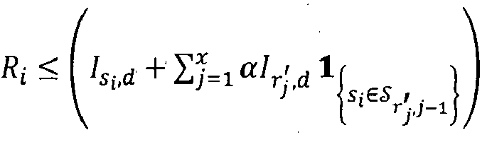

- b. si non, aucune source n'est décodée par la destination :

Si non (x = X) alors out = out + 1, retourner à l'étape 3.
- a. si
- 9. déterminer la probabilité de coupure moyenne de la source si pour le débit Rg comme étant (en résolvant l'intégrale de l'inégalité (10) en utilisant les simulations Monte-Carlo) :

- 10. choisir le débit maximum Ri que la source si peut utiliser :

- 1. sequentially select the first possible candidate rate R g which has not yet been considered in the set { R 1 , ..., R n
CSM }. If all debits have been considered go to step 10. - 2. initialize the counter cnt of the current realization of a Monte-Carlo simulation: cnt = 0. Initialization of the counter out of the Monte-Carlo realizations (of channel matrix H and of X relay nodes) which lead to a cut: out = 0.
- 3. increment counter cnt by one.
If cnt ≤ max_ cnt with max_ cnt the maximum number of Monte-Carlo realizations, for example max_ cnt = 1000 then:- To. randomly determine X relay nodes among the set { r 1 , ... , r L+M -1 } of relay nodes and note the
- b. determine H on the basis of P ( H ) the joint probability of the realizations of the channels of all the links h a,b .
If not ( cnt > max_cnt ) go to step 9.
- To. randomly determine X relay nodes among the set { r 1 , ... , r L+M -1 } of relay nodes and note the
- 4. Calculate Is
I ,d and determine the destination decode set as follows:- To. if R i ≤ I s
I ,d then - b. if not ( R i > I s
I ,d ) then
- To. if R i ≤ I s
- 5. initialize the counter of the current round to x = 1
- 6. calculate
- 7. Determine relay decoding set
- To. whether
- b. if not then
- To. whether
- 8. Determine the destination decode set after round x as follows:
- To. whether
- b. if not, no source is decoded by the destination:
If not ( x = X) then out = out + 1, go back to step 3.
- To. whether
- 9. determine the mean outage probability of the source s i for the rate R g as being (by solving the integral of inequality (10) using Monte-Carlo simulations):
step 1. - 10. choose the maximum rate R i that the source s i can use:
Les étapes de 1 à 10 sont répétées pour chacune des autres sources si pour déterminer chacun des débits Ri ,
Les M débits pris ensemble peuvent ensuite être diminués ou augmentés simultanément en utilisant une méthode de Newton. Ainsi, si la détermination du membre de gauche de l'inégalité (9) conduit à un résultat supérieur ou inférieur à la probabilité de coupure commune cible εcom il est possible de respectivement diminuer ou augmenter tous les débits simultanément jusqu'aux débits respectivement juste inférieurs ou juste supérieurs dans le cas d'un nombre fini de MCSs disponibles. Cette diminution ou augmentation est répétée jusqu'à conduire à un résultat inférieur à la probabilité de coupure commune cible εcom de telle manière que l'augmentation des débits conduise à une probabilité de coupure commune supérieure à εcom .The M flow rates taken together can then be decreased or increased simultaneously using a Newton method. Thus, if the determination of the left member of the inequality (9) leads to a result higher or lower than the target common cut-off probability ε com it is possible to respectively decrease or increase all the bit rates simultaneously up to the bit rates respectively just below or just above in the case of a finite number of MCSs available. This decrease or increase is repeated until leading to a result lower than the target common outage probability ε com in such a way that the increase in the bit rates leads to a common outage probability greater than ε com .
Au final, la somme des débits a été maximisée sous contrainte de la probabilité de coupure commune cible εcom .In the end, the sum of the flows was maximized under the constraint of the target common outage probability ε com .
La probabilité de coupure commune εcom peut en outre éventuellement être affinée pour tendre vers une solution optimale.The common cut-off probability ε com can also possibly be refined to tend towards an optimal solution.
Les débits ayant été initialisés, par exemple selon le mode décrit précédemment, les sources si émettent pendant la 1ère phase chacune à leur tour leur message avec leur débit initial à destination du destinataire. A réception, la destination tente de décoder les messages reçus. Généralement, tous les messages ne sont pas décodés correctement par la destination à l'issue de la 1ère phase d'où l'intérêt de la 2nde phase.The bit rates having been initialized, for example according to the mode described previously, the sources s i transmit during the 1 st phase each in turn their message with their initial bit rate intended for the recipient. On reception, the destination tries to decode the received messages. Generally, all the messages are not decoded correctly by the destination at the end of the 1 st phase, hence the interest of the 2 nd phase.
Lors de la 2nde phase, il y a une transmission coopérative par un ou par plusieurs dispositifs pris parmi les sources et les relais. Une source peut ainsi coopérer avec elle-même mais en outre avec une ou plusieurs sources.During the 2 nd phase, there is a cooperative transmission by one or more devices taken from among the sources and the relays. A source can thus cooperate with itself but also with one or more sources.
Selon un mode de réalisation, dite à haute charge de signalisation, la maximisation du débit défini par l'équation (1) est obtenue en minimisant la probabilité de coupure commune Pr{E t } à chaque round t en sélectionnant le noeud relais approprié connaissant le canal h et conditionnel à P t-1. Compte tenu que pour toute source s ∈ S Pr{O s,T
Selon ce mode, si la destination décode correctement tous les messages elle transmet un message commun ACK. La transmission d'une nouvelle trame débute à réception de cet ACK. Si la destination ne décode pas correctement tous les messages elle transmet un message commun NACK sous la forme par exemple d'un bit au début de chaque round t ∈ {1,..., Tmax ). En réponse, les noeuds relais transmettent à la destination une mise à jour de leur jeu de messages décodés correctement sous la forme par exemple de M + L bits. Chaque noeud relais peut coopérer avec son propre jeu de messages décodés correctement. La destination transmet ensuite ![]()
![]()
![]()
![]()
![]()
![]()
Une première réalisation considère un message ACK/NACK commun et une sélection d'un noeud relais basée sur l'information mutuelle.A first embodiment considers a common ACK/NACK message and a selection of a relay node based on the mutual information.
Selon cette réalisation, seul un sous-jeu ![]()
![]()
![]()

![]()
![]()
![]()
Compte tenu que le choix de at n'influence pas les deux premiers membres de la partie droite de l'inégalité (7) alors le problème de maximisation peut être transformé en une maximisation du troisième membre :
![]()
![]()
![]()
![]()
![]()
![]()
![]()
![]()
![]()
![]()
Une deuxième réalisation considère un message ACK/NACK commun et une sélection d'un noeud relais basée sur le produit d'informations mutuelles et sur la cardinalité du jeu de décodage.A second embodiment considers a common ACK/NACK message and selection of a relay node based on the mutual information product and the cardinality of the decode set.
Selon cette réalisation, la sélection porte sur le noeud avec le produit le plus
![]()
![]()
![]()
![]()
Une troisième réalisation considère un message ACK/NACK commun et une sélection d'un noeud relais basée sur une prédiction des sources décodées.A third embodiment considers a common ACK/NACK message and a selection of a relay node based on a prediction of the decoded sources.
Selon cette réalisation, à chaque round, la destination examine séquentiellement les sources de s 1 à sM et puis les relais de r 1 à rL . Pour chaque noeud at parmi ces noeuds et à condition que
![]()
![]()
A cette fin, pour chacun de ces noeuds at la destination vérifie pour chaque source
![]()
![]()
![]()
![]()
Selon une alternative moins coûteuse en nombre d'opérations, la destination vérifie les événements de coupure commune des sous-jeux du jeu de décodage
![]()
![]()
Pour qu'un jeu de sources soit le jeu
![]()
![]()
![]()
![]()
![]()
![]()
![]()
![]()
![]()
![]()
![]()
![]()
![]()
![]()
![]()
![]()
![]()
![]()
![]()
![]()
![]()
![]()
Selon cette alternative, la destination part du sous-jeu le plus grand du jeu de décodage
![]()
![]()
![]()
![]()
![]()
![]()
![]()
![]()
![]()
![]()
![]()
![]()
![]()
![]()
![]()
![]()
![]()
![]()
![]()
![]()
![]()
![]()
![]()
![]()
![]()
![]()
![]()
![]()
![]()
![]()
![]()
![]()
![]()
![]()
![]()
![]()
Vérifier (ii) si l'événement de coupure commune est vrai pour des sous-jeux ![]()
![]()
![]()
![]()
![]()
![]()
![]()
![]()
![]()
![]()
![]()
![]()
![]()
![]()
![]()


![]()
![]()
![]()
![]()
![]()
![]()
![]()
![]()
![]()
![]()
![]()
![]()
![]()
![]()
![]()
Dit autrement, selon cette alternative la destination effectue les opérations suivantes :
- 1. initialisation d'une variable i dénotant la cardinalité du jeu observé à :


- 2. De manière séquentielle, prendre le noeud at coopérant candidat potentiel suivant pas encore considéré du jeu {s 1 ,..., sM, r 1 , ... , rL } et pour lequel

- 3. au round i calculer la fonction

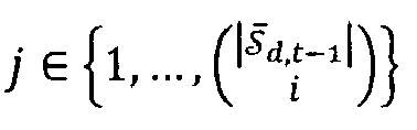
- 4. Si


- a. si i > 1 décrémenter i et retourner à l'étape 3.
- b. si i = 1 retourner à l'étape 2 (v(at ) reste égale à zéro). Si non, si

- 5. Tous les noeuds at candidats ayant été considérés, prendre celui


- 1. initialization of a variable i denoting the cardinality of the game observed at:
- 2. Sequentially, take the next potential candidate cooperating node a t not yet considered from the set { s 1 ,..., s M , r 1 , ... , r L } and for which
- 3. in round i calculate the function
- 4. If
- To. if i > 1 decrement i and return to step 3.
- b. if i = 1 return to step 2 ( v ( a t ) remains equal to zero). Else if
step 2.
- 5. All the candidate nodes having been considered, take the one
Pour chacune des trois réalisations à haute charge de signalisation, le nombre de bits de signalisation (feedback) par round pour le message ACK/NACK commun et le message de sélection de noeud est au plus : ![]()
![]()
Selon un mode de réalisation, dite à faible charge de signalisation, la sélection des noeuds pour les X premiers rounds est déterminée de manière aléatoire en avance. Chacun des noeuds du réseau utilise un générateur aléatoire avec un même aléa. Ainsi il n'y a pas de signalisation de retour (feedback) portant une information de sélection de noeuds depuis la destination vers les noeuds coopératifs ce qui permet de réduire la bande passante occupée par la signalisation en particulier par rapport au mode avec haute charge de signalisation. Deux mises en oeuvre simples sont décrites.According to an embodiment, called low signaling load, the selection of the nodes for the first X rounds is determined randomly in advance. Each of the network nodes uses a random generator with the same randomness. Thus there is no return signaling (feedback) carrying node selection information from the destination to the cooperative nodes, which makes it possible to reduce the bandwidth occupied by the signaling in particular compared to the mode with high signaling load. Two simple implementations are described.
Une première mise en oeuvre avec sélection aléatoire considère qu'il n'y a pas de message ACK/NACK commun à la fin de chacun des X rounds. Ainsi, que la destination ait décodé ou pas les sources avant la fin d'un round, il y a coopération du noeud relais sélectionné aléatoirement. Dans un 1 - ε com pourcentage des cas il n'y a aucun échange de signalisation pendant la 2nde phase.A first implementation with random selection considers that there is no common ACK/NACK message at the end of each of the X rounds. Thus, whether or not the destination has decoded the sources before the end of a round, there is cooperation from the randomly selected relay node. In a 1 - ε com percentage of cases there is no signaling exchange during the 2 nd phase.
Une deuxième mise en oeuvre avec sélection aléatoire prend en compte un message ACK/NACK commun à la fin de chacun des X rounds pour stopper la coopération en cas de ACK et basculer sur une nouvelle trame. Selon cette mise en oeuvre un décodage correct de toutes les sources par la destination peut donc permettre de stopper les transmissions coopératives au prix d'un bit de signalisation par round.A second implementation with random selection takes into account a common ACK/NACK message at the end of each of the X rounds to stop cooperation in the event of an ACK and switch to a new frame. According to this implementation, a correct decoding of all the sources by the destination can therefore make it possible to stop the cooperative transmissions at the cost of one signaling bit per round.
-
[1]
A. Mohamad, R. Visoz and A. O. Berthet, "Cooperative Incremental Redundancy Hybrid Automatic Repeat Request Strategies for Multi-Source Multi-Relay Wireless Networks," in IEEE Communications Letters, vol. 20, no. 9, pp. 1808-1811, September 2016 A. Mohamad, R. Visoz and AO Berthet, "Cooperative Incremental Redundancy Hybrid Automatic Repeat Request Strategies for Multi-Source Multi-Relay Wireless Networks," in IEEE Communications Letters, vol. 20, no. 9, p. 1808-1811, September 2016
Claims (8)
- Method (1) for transmitting successive messages forming a frame in a telecommunication system with M sources (s 1 ,...,sM ), L relays (r 1 ,...,rL ) and a destination (d), M > 1, L ≥ 1 according to an orthogonal multiple-access channel scheme between the M sources and the L relays with a maximum number of M +Tmax time intervals per frame transmitted, including M intervals allocated during a first phase to the successive transmission of the M sources, and Tmax cooperative transmission intervals allocated during a second phase to one or more nodes taken from among the sources and the relays according to a determined selection, characterized in that it comprises:- an initial phase of link adaptation with an initial rate being determined for each source by the destination on the basis of an average SNR of each of the links of the system and with this initial rate being transmitted to each source,- for each frame from among several frames, successively transmitting the messages from the M sources during the M intervals of the first phase with respective modulation and coding schemes determined on the basis of the initial rates,and characterized in that, in order to maximize the total rate of all the sources under the constraint of a target average BLER εcom at the end of X ≥ 1 cooperative transmissions, the method comprises maximizing the individual rate of each source, considering the known messages from the other sources under the constraint of a target individual average BLER εcom /M at the end of the X cooperative transmissions, and, after maximization, simultaneously decreasing or increasing the M individual rates taken together until a common outage probability which is less than εcom is obtained.
- Transmission method (1) according to Claim 1, according to which the method further comprises, during the 2nd phase at the end of the X cooperative transmissions:- a cooperative transmission of one or more nodes taken from among the sources and the relays according to a selection of IR-HARQ type.
- Transmission method (1) according to one of Claims 1 and 2, according to which the selection of a node (at ) at an interval t from among the nodes which correctly decoded at the interval t - 1 at least one source (s) which the destination did not correctly decode at this interval t - 1 is determined by the destination, taking into account the gains (h = [hs
1 ,d, ..., hsM ,d, h r1 ,d, ..., hrL ,d ]) of the channels between the nodes and the destination. - Transmission method (1) according to Claim 3, according to which the selected node (at ) is the one the channel with the destination of which has the best gain.
- Transmission method (1) according to one of Claims 1 and 2, according to which the X cooperative transmissions occur according to a selection which is known by the destination and the relays in advance.
- Transmission method (1) according to one of Claims 1 and 2, according to which the selection is determined by the destination and is of IR-HARQ type for all the cooperative transmissions.
- Transmission method (1) according to one of Claims 2 and 6, according to which, for any selection of IR-HARQ type, the destination selects the node which maximizes the number of sources decoded correctly after retransmission by this node, the number of correctly decoded sources originating from a prediction by the destination.
- System comprising M sources (s 1,...,sM ), L relays (r 1 ,...,rL) and a destination (d), M > 1, L ≥ 1, with link adaptation, for implementing a transmission method according to one of Claims 1 to 7.
Applications Claiming Priority (2)
| Application Number | Priority Date | Filing Date | Title |
|---|---|---|---|
| FR1755212A FR3067543A1 (en) | 2017-06-12 | 2017-06-12 | METHOD AND SYSTEM OF TRANSMISSION OMAMRC WITH SLOW LINK ADAPTATION |
| PCT/FR2018/000162 WO2018229362A1 (en) | 2017-06-12 | 2018-06-06 | Omamrc transmission method and system with slow-link adaptation |
Publications (2)
| Publication Number | Publication Date |
|---|---|
| EP3639427A1 EP3639427A1 (en) | 2020-04-22 |
| EP3639427B1 true EP3639427B1 (en) | 2023-07-26 |
Family
ID=60138434
Family Applications (1)
| Application Number | Title | Priority Date | Filing Date |
|---|---|---|---|
| EP18742840.4A Active EP3639427B1 (en) | 2017-06-12 | 2018-06-06 | Omamrc transmission method and system with slow-link adaptation |
Country Status (4)
| Country | Link |
|---|---|
| US (1) | US11418252B2 (en) |
| EP (1) | EP3639427B1 (en) |
| FR (1) | FR3067543A1 (en) |
| WO (1) | WO2018229362A1 (en) |
Families Citing this family (4)
| Publication number | Priority date | Publication date | Assignee | Title |
|---|---|---|---|---|
| FR3110309A1 (en) * | 2020-05-12 | 2021-11-19 | Orange | OMAMRC method and transmission system with variation in the number of channel uses |
| FR3111495A1 (en) * | 2020-06-24 | 2021-12-17 | Orange | OMAMRC method and system with FDM transmission |
| FR3118551A1 (en) * | 2020-12-24 | 2022-07-01 | Orange | Method of receiving at least one data frame in an OMAMRC system, corresponding destination, computer program and system. |
| FR3124912A1 (en) * | 2021-07-01 | 2023-01-06 | Orange | Method of cooperative retransmission in an OMAMRC system |
Family Cites Families (4)
| Publication number | Priority date | Publication date | Assignee | Title |
|---|---|---|---|---|
| CN101682465B (en) * | 2007-05-07 | 2016-01-06 | 诺基亚公司 | For feedback and the link adaptation techniques of wireless network |
| CN101212285B (en) * | 2007-12-25 | 2010-08-18 | 中国人民解放军理工大学 | Opportunity synergy based automatic retransmission request method |
| CN102577290A (en) * | 2009-08-12 | 2012-07-11 | 捷讯研究有限公司 | System and method for modulation and coding scheme adaptation and power control in a relay network |
| CN105979562B (en) * | 2016-04-13 | 2019-04-26 | 东北大学 | It can guarantee the relay node selecting method of global bit error rate performance in collaboration communication |
-
2017
- 2017-06-12 FR FR1755212A patent/FR3067543A1/en active Pending
-
2018
- 2018-06-06 US US16/621,519 patent/US11418252B2/en active Active
- 2018-06-06 EP EP18742840.4A patent/EP3639427B1/en active Active
- 2018-06-06 WO PCT/FR2018/000162 patent/WO2018229362A1/en unknown
Also Published As
| Publication number | Publication date |
|---|---|
| EP3639427A1 (en) | 2020-04-22 |
| US20200119804A1 (en) | 2020-04-16 |
| US11418252B2 (en) | 2022-08-16 |
| WO2018229362A1 (en) | 2018-12-20 |
| FR3067543A1 (en) | 2018-12-14 |
Similar Documents
| Publication | Publication Date | Title |
|---|---|---|
| EP3639427B1 (en) | Omamrc transmission method and system with slow-link adaptation | |
| EP3756295A1 (en) | Omamrc transmission method and system with slow link adaptation under bler constraint | |
| EP3387773B1 (en) | Relaying method and device and recipient with return in an omamrc system | |
| EP3161986B1 (en) | Method for dynamic and selective fd-dsdf transmission of a digital signal for a mamrc system with several full-duplex relays, and corresponding program product and relay device | |
| EP2385648A1 (en) | Cooperative network with adaptive retransmission request strategy | |
| EP2784967B1 (en) | Cooperative communication system with adaptive packet retransmission strategy | |
| EP3476071B1 (en) | Dynamic and selective transmission of a digital signal for a system with full-duplex relay and a limited return path | |
| EP3769451B1 (en) | Method and system for omamrc transmission with reduced signalling | |
| WO2021260308A1 (en) | Omamrc method and system with fdm transmission | |
| EP4150808A1 (en) | Omamrc transmission method and system with variation in the number of uses of the channel | |
| EP3161985A1 (en) | Method for dynamic and selective fd-dsdf transmission of a digital signal for a marc system with a full-duplex relay, and corresponding program product and relay device | |
| WO2024002886A1 (en) | Transmission method and omamrc system with a selection strategy during retransmissions taking into account the throughput of the sources and of one or more control exchanges | |
| WO2024079158A1 (en) | Omamrc method and system with fdm transmission and multiple cooperations per sub-band | |
| WO2024002899A1 (en) | Transmission method and omamrc system with a selection strategy during retransmissions taking into account the throughput of the sources and of a single control exchange | |
| WO2023275469A1 (en) | Method for cooperative retransmission in an omamrc system | |
| WO2024002898A1 (en) | Cooperative retransmission method in omamrc system | |
| WO2023242295A1 (en) | Method for cooperative retransmission in an omamrc system | |
| WO2024079309A1 (en) | Cooperative retransmission method in an omamrc system with joint resource allocation and selections of the sources to be helped | |
| FR3118551A1 (en) | Method of receiving at least one data frame in an OMAMRC system, corresponding destination, computer program and system. |
Legal Events
| Date | Code | Title | Description |
|---|---|---|---|
| STAA | Information on the status of an ep patent application or granted ep patent |
Free format text: STATUS: UNKNOWN |
|
| STAA | Information on the status of an ep patent application or granted ep patent |
Free format text: STATUS: THE INTERNATIONAL PUBLICATION HAS BEEN MADE |
|
| PUAI | Public reference made under article 153(3) epc to a published international application that has entered the european phase |
Free format text: ORIGINAL CODE: 0009012 |
|
| STAA | Information on the status of an ep patent application or granted ep patent |
Free format text: STATUS: REQUEST FOR EXAMINATION WAS MADE |
|
| 17P | Request for examination filed |
Effective date: 20191216 |
|
| AK | Designated contracting states |
Kind code of ref document: A1 Designated state(s): AL AT BE BG CH CY CZ DE DK EE ES FI FR GB GR HR HU IE IS IT LI LT LU LV MC MK MT NL NO PL PT RO RS SE SI SK SM TR |
|
| AX | Request for extension of the european patent |
Extension state: BA ME |
|
| RAP1 | Party data changed (applicant data changed or rights of an application transferred) |
Owner name: ORANGE |
|
| DAV | Request for validation of the european patent (deleted) | ||
| DAX | Request for extension of the european patent (deleted) | ||
| STAA | Information on the status of an ep patent application or granted ep patent |
Free format text: STATUS: EXAMINATION IS IN PROGRESS |
|
| 17Q | First examination report despatched |
Effective date: 20210629 |
|
| RAP3 | Party data changed (applicant data changed or rights of an application transferred) |
Owner name: ORANGE |
|
| REG | Reference to a national code |
Ref country code: DE Ref legal event code: R079 Ref document number: 602018054050 Country of ref document: DE Free format text: PREVIOUS MAIN CLASS: H04L0001000000 Ipc: H04L0001182900 Ref country code: DE Ref legal event code: R079 Free format text: PREVIOUS MAIN CLASS: H04L0001000000 Ipc: H04L0001182900 |
|
| GRAP | Despatch of communication of intention to grant a patent |
Free format text: ORIGINAL CODE: EPIDOSNIGR1 |
|
| STAA | Information on the status of an ep patent application or granted ep patent |
Free format text: STATUS: GRANT OF PATENT IS INTENDED |
|
| RIC1 | Information provided on ipc code assigned before grant |
Ipc: H04L 1/00 20060101ALN20230206BHEP Ipc: H04L 1/1812 20230101ALI20230206BHEP Ipc: H04L 1/1829 20230101AFI20230206BHEP |
|
| RIC1 | Information provided on ipc code assigned before grant |
Ipc: H04L 1/00 20060101ALN20230215BHEP Ipc: H04L 1/1812 20230101ALI20230215BHEP Ipc: H04L 1/1829 20230101AFI20230215BHEP |
|
| INTG | Intention to grant announced |
Effective date: 20230302 |
|
| RIN1 | Information on inventor provided before grant (corrected) |
Inventor name: VISOZ, RAPHAEL Inventor name: MOHAMAD, ABDULAZIZ Inventor name: CEROVIC, STEPHAN |
|
| GRAS | Grant fee paid |
Free format text: ORIGINAL CODE: EPIDOSNIGR3 |
|
| GRAA | (expected) grant |
Free format text: ORIGINAL CODE: 0009210 |
|
| STAA | Information on the status of an ep patent application or granted ep patent |
Free format text: STATUS: THE PATENT HAS BEEN GRANTED |
|
| AK | Designated contracting states |
Kind code of ref document: B1 Designated state(s): AL AT BE BG CH CY CZ DE DK EE ES FI FR GB GR HR HU IE IS IT LI LT LU LV MC MK MT NL NO PL PT RO RS SE SI SK SM TR |
|
| REG | Reference to a national code |
Ref country code: CH Ref legal event code: EP |
|
| REG | Reference to a national code |
Ref country code: IE Ref legal event code: FG4D Free format text: LANGUAGE OF EP DOCUMENT: FRENCH |
|
| REG | Reference to a national code |
Ref country code: DE Ref legal event code: R096 Ref document number: 602018054050 Country of ref document: DE |
|
| REG | Reference to a national code |
Ref country code: LT Ref legal event code: MG9D |
|
| REG | Reference to a national code |
Ref country code: NL Ref legal event code: MP Effective date: 20230726 |
|
| REG | Reference to a national code |
Ref country code: AT Ref legal event code: MK05 Ref document number: 1593194 Country of ref document: AT Kind code of ref document: T Effective date: 20230726 |
|
| PG25 | Lapsed in a contracting state [announced via postgrant information from national office to epo] |
Ref country code: NL Free format text: LAPSE BECAUSE OF FAILURE TO SUBMIT A TRANSLATION OF THE DESCRIPTION OR TO PAY THE FEE WITHIN THE PRESCRIBED TIME-LIMIT Effective date: 20230726 |
|
| PG25 | Lapsed in a contracting state [announced via postgrant information from national office to epo] |
Ref country code: GR Free format text: LAPSE BECAUSE OF FAILURE TO SUBMIT A TRANSLATION OF THE DESCRIPTION OR TO PAY THE FEE WITHIN THE PRESCRIBED TIME-LIMIT Effective date: 20231027 |
|
| PG25 | Lapsed in a contracting state [announced via postgrant information from national office to epo] |
Ref country code: IS Free format text: LAPSE BECAUSE OF FAILURE TO SUBMIT A TRANSLATION OF THE DESCRIPTION OR TO PAY THE FEE WITHIN THE PRESCRIBED TIME-LIMIT Effective date: 20231126 |
|
| PG25 | Lapsed in a contracting state [announced via postgrant information from national office to epo] |
Ref country code: SE Free format text: LAPSE BECAUSE OF FAILURE TO SUBMIT A TRANSLATION OF THE DESCRIPTION OR TO PAY THE FEE WITHIN THE PRESCRIBED TIME-LIMIT Effective date: 20230726 Ref country code: RS Free format text: LAPSE BECAUSE OF FAILURE TO SUBMIT A TRANSLATION OF THE DESCRIPTION OR TO PAY THE FEE WITHIN THE PRESCRIBED TIME-LIMIT Effective date: 20230726 Ref country code: PT Free format text: LAPSE BECAUSE OF FAILURE TO SUBMIT A TRANSLATION OF THE DESCRIPTION OR TO PAY THE FEE WITHIN THE PRESCRIBED TIME-LIMIT Effective date: 20231127 Ref country code: NO Free format text: LAPSE BECAUSE OF FAILURE TO SUBMIT A TRANSLATION OF THE DESCRIPTION OR TO PAY THE FEE WITHIN THE PRESCRIBED TIME-LIMIT Effective date: 20231026 Ref country code: LV Free format text: LAPSE BECAUSE OF FAILURE TO SUBMIT A TRANSLATION OF THE DESCRIPTION OR TO PAY THE FEE WITHIN THE PRESCRIBED TIME-LIMIT Effective date: 20230726 Ref country code: LT Free format text: LAPSE BECAUSE OF FAILURE TO SUBMIT A TRANSLATION OF THE DESCRIPTION OR TO PAY THE FEE WITHIN THE PRESCRIBED TIME-LIMIT Effective date: 20230726 Ref country code: IS Free format text: LAPSE BECAUSE OF FAILURE TO SUBMIT A TRANSLATION OF THE DESCRIPTION OR TO PAY THE FEE WITHIN THE PRESCRIBED TIME-LIMIT Effective date: 20231126 Ref country code: HR Free format text: LAPSE BECAUSE OF FAILURE TO SUBMIT A TRANSLATION OF THE DESCRIPTION OR TO PAY THE FEE WITHIN THE PRESCRIBED TIME-LIMIT Effective date: 20230726 Ref country code: GR Free format text: LAPSE BECAUSE OF FAILURE TO SUBMIT A TRANSLATION OF THE DESCRIPTION OR TO PAY THE FEE WITHIN THE PRESCRIBED TIME-LIMIT Effective date: 20231027 Ref country code: FI Free format text: LAPSE BECAUSE OF FAILURE TO SUBMIT A TRANSLATION OF THE DESCRIPTION OR TO PAY THE FEE WITHIN THE PRESCRIBED TIME-LIMIT Effective date: 20230726 Ref country code: AT Free format text: LAPSE BECAUSE OF FAILURE TO SUBMIT A TRANSLATION OF THE DESCRIPTION OR TO PAY THE FEE WITHIN THE PRESCRIBED TIME-LIMIT Effective date: 20230726 |
|
| PG25 | Lapsed in a contracting state [announced via postgrant information from national office to epo] |
Ref country code: PL Free format text: LAPSE BECAUSE OF FAILURE TO SUBMIT A TRANSLATION OF THE DESCRIPTION OR TO PAY THE FEE WITHIN THE PRESCRIBED TIME-LIMIT Effective date: 20230726 |