EP3638924B1 - Differential lock/unlock position detection - Google Patents
Differential lock/unlock position detection Download PDFInfo
- Publication number
- EP3638924B1 EP3638924B1 EP18818671.2A EP18818671A EP3638924B1 EP 3638924 B1 EP3638924 B1 EP 3638924B1 EP 18818671 A EP18818671 A EP 18818671A EP 3638924 B1 EP3638924 B1 EP 3638924B1
- Authority
- EP
- European Patent Office
- Prior art keywords
- sensor assembly
- armature
- differential
- sensor
- differential case
- Prior art date
- Legal status (The legal status is an assumption and is not a legal conclusion. Google has not performed a legal analysis and makes no representation as to the accuracy of the status listed.)
- Active
Links
Images




Classifications
-
- F—MECHANICAL ENGINEERING; LIGHTING; HEATING; WEAPONS; BLASTING
- F16—ENGINEERING ELEMENTS AND UNITS; GENERAL MEASURES FOR PRODUCING AND MAINTAINING EFFECTIVE FUNCTIONING OF MACHINES OR INSTALLATIONS; THERMAL INSULATION IN GENERAL
- F16H—GEARING
- F16H48/00—Differential gearings
- F16H48/38—Constructional details
-
- B—PERFORMING OPERATIONS; TRANSPORTING
- B60—VEHICLES IN GENERAL
- B60K—ARRANGEMENT OR MOUNTING OF PROPULSION UNITS OR OF TRANSMISSIONS IN VEHICLES; ARRANGEMENT OR MOUNTING OF PLURAL DIVERSE PRIME-MOVERS IN VEHICLES; AUXILIARY DRIVES FOR VEHICLES; INSTRUMENTATION OR DASHBOARDS FOR VEHICLES; ARRANGEMENTS IN CONNECTION WITH COOLING, AIR INTAKE, GAS EXHAUST OR FUEL SUPPLY OF PROPULSION UNITS IN VEHICLES
- B60K17/00—Arrangement or mounting of transmissions in vehicles
- B60K17/04—Arrangement or mounting of transmissions in vehicles characterised by arrangement, location or kind of gearing
- B60K17/16—Arrangement or mounting of transmissions in vehicles characterised by arrangement, location or kind of gearing of differential gearing
-
- F—MECHANICAL ENGINEERING; LIGHTING; HEATING; WEAPONS; BLASTING
- F16—ENGINEERING ELEMENTS AND UNITS; GENERAL MEASURES FOR PRODUCING AND MAINTAINING EFFECTIVE FUNCTIONING OF MACHINES OR INSTALLATIONS; THERMAL INSULATION IN GENERAL
- F16H—GEARING
- F16H48/00—Differential gearings
- F16H48/20—Arrangements for suppressing or influencing the differential action, e.g. locking devices
- F16H48/24—Arrangements for suppressing or influencing the differential action, e.g. locking devices using positive clutches or brakes
-
- F—MECHANICAL ENGINEERING; LIGHTING; HEATING; WEAPONS; BLASTING
- F16—ENGINEERING ELEMENTS AND UNITS; GENERAL MEASURES FOR PRODUCING AND MAINTAINING EFFECTIVE FUNCTIONING OF MACHINES OR INSTALLATIONS; THERMAL INSULATION IN GENERAL
- F16H—GEARING
- F16H57/00—General details of gearing
- F16H57/02—Gearboxes; Mounting gearing therein
- F16H57/037—Gearboxes for accommodating differential gearings
-
- G—PHYSICS
- G01—MEASURING; TESTING
- G01D—MEASURING NOT SPECIALLY ADAPTED FOR A SPECIFIC VARIABLE; ARRANGEMENTS FOR MEASURING TWO OR MORE VARIABLES NOT COVERED IN A SINGLE OTHER SUBCLASS; TARIFF METERING APPARATUS; MEASURING OR TESTING NOT OTHERWISE PROVIDED FOR
- G01D5/00—Mechanical means for transferring the output of a sensing member; Means for converting the output of a sensing member to another variable where the form or nature of the sensing member does not constrain the means for converting; Transducers not specially adapted for a specific variable
- G01D5/12—Mechanical means for transferring the output of a sensing member; Means for converting the output of a sensing member to another variable where the form or nature of the sensing member does not constrain the means for converting; Transducers not specially adapted for a specific variable using electric or magnetic means
-
- G—PHYSICS
- G01—MEASURING; TESTING
- G01D—MEASURING NOT SPECIALLY ADAPTED FOR A SPECIFIC VARIABLE; ARRANGEMENTS FOR MEASURING TWO OR MORE VARIABLES NOT COVERED IN A SINGLE OTHER SUBCLASS; TARIFF METERING APPARATUS; MEASURING OR TESTING NOT OTHERWISE PROVIDED FOR
- G01D5/00—Mechanical means for transferring the output of a sensing member; Means for converting the output of a sensing member to another variable where the form or nature of the sensing member does not constrain the means for converting; Transducers not specially adapted for a specific variable
- G01D5/12—Mechanical means for transferring the output of a sensing member; Means for converting the output of a sensing member to another variable where the form or nature of the sensing member does not constrain the means for converting; Transducers not specially adapted for a specific variable using electric or magnetic means
- G01D5/25—Selecting one or more conductors or channels from a plurality of conductors or channels, e.g. by closing contacts
- G01D5/251—Selecting one or more conductors or channels from a plurality of conductors or channels, e.g. by closing contacts one conductor or channel
- G01D5/2515—Selecting one or more conductors or channels from a plurality of conductors or channels, e.g. by closing contacts one conductor or channel with magnetically controlled switches, e.g. by movement of a magnet
-
- F—MECHANICAL ENGINEERING; LIGHTING; HEATING; WEAPONS; BLASTING
- F16—ENGINEERING ELEMENTS AND UNITS; GENERAL MEASURES FOR PRODUCING AND MAINTAINING EFFECTIVE FUNCTIONING OF MACHINES OR INSTALLATIONS; THERMAL INSULATION IN GENERAL
- F16H—GEARING
- F16H48/00—Differential gearings
- F16H48/20—Arrangements for suppressing or influencing the differential action, e.g. locking devices
- F16H2048/204—Control of arrangements for suppressing differential actions
-
- F—MECHANICAL ENGINEERING; LIGHTING; HEATING; WEAPONS; BLASTING
- F16—ENGINEERING ELEMENTS AND UNITS; GENERAL MEASURES FOR PRODUCING AND MAINTAINING EFFECTIVE FUNCTIONING OF MACHINES OR INSTALLATIONS; THERMAL INSULATION IN GENERAL
- F16H—GEARING
- F16H48/00—Differential gearings
- F16H48/38—Constructional details
- F16H2048/382—Methods for manufacturing differential gearings
-
- F—MECHANICAL ENGINEERING; LIGHTING; HEATING; WEAPONS; BLASTING
- F16—ENGINEERING ELEMENTS AND UNITS; GENERAL MEASURES FOR PRODUCING AND MAINTAINING EFFECTIVE FUNCTIONING OF MACHINES OR INSTALLATIONS; THERMAL INSULATION IN GENERAL
- F16H—GEARING
- F16H57/00—General details of gearing
- F16H57/02—Gearboxes; Mounting gearing therein
- F16H2057/02026—Connection of auxiliaries with a gear case; Mounting of auxiliaries on the gearbox
-
- F—MECHANICAL ENGINEERING; LIGHTING; HEATING; WEAPONS; BLASTING
- F16—ENGINEERING ELEMENTS AND UNITS; GENERAL MEASURES FOR PRODUCING AND MAINTAINING EFFECTIVE FUNCTIONING OF MACHINES OR INSTALLATIONS; THERMAL INSULATION IN GENERAL
- F16H—GEARING
- F16H57/00—General details of gearing
- F16H57/02—Gearboxes; Mounting gearing therein
- F16H2057/02039—Gearboxes for particular applications
- F16H2057/02043—Gearboxes for particular applications for vehicle transmissions
-
- F—MECHANICAL ENGINEERING; LIGHTING; HEATING; WEAPONS; BLASTING
- F16—ENGINEERING ELEMENTS AND UNITS; GENERAL MEASURES FOR PRODUCING AND MAINTAINING EFFECTIVE FUNCTIONING OF MACHINES OR INSTALLATIONS; THERMAL INSULATION IN GENERAL
- F16H—GEARING
- F16H48/00—Differential gearings
- F16H48/06—Differential gearings with gears having orbital motion
- F16H48/08—Differential gearings with gears having orbital motion comprising bevel gears
-
- F—MECHANICAL ENGINEERING; LIGHTING; HEATING; WEAPONS; BLASTING
- F16—ENGINEERING ELEMENTS AND UNITS; GENERAL MEASURES FOR PRODUCING AND MAINTAINING EFFECTIVE FUNCTIONING OF MACHINES OR INSTALLATIONS; THERMAL INSULATION IN GENERAL
- F16H—GEARING
- F16H48/00—Differential gearings
- F16H48/20—Arrangements for suppressing or influencing the differential action, e.g. locking devices
- F16H48/30—Arrangements for suppressing or influencing the differential action, e.g. locking devices using externally-actuatable means
- F16H48/34—Arrangements for suppressing or influencing the differential action, e.g. locking devices using externally-actuatable means using electromagnetic or electric actuators
-
- F—MECHANICAL ENGINEERING; LIGHTING; HEATING; WEAPONS; BLASTING
- F16—ENGINEERING ELEMENTS AND UNITS; GENERAL MEASURES FOR PRODUCING AND MAINTAINING EFFECTIVE FUNCTIONING OF MACHINES OR INSTALLATIONS; THERMAL INSULATION IN GENERAL
- F16H—GEARING
- F16H59/00—Control inputs to control units of change-speed- or reversing-gearings for conveying rotary motion
- F16H59/68—Inputs being a function of gearing status
Definitions
- the present invention relates, in general, to electronically actuated locking differentials and, in particular to a sensor assembly configured to couple to a differential case of a locking differential, the sensor assembly configured to determine a position of an armature in relation to a stator in the locking differential.
- an electronically actuated locking differential of the related art may be actuated electronically and is designed for forward-wheel-drive (FWD), rear-wheel-drive (RWD), all-wheel-drive (AWD), and four-wheel-drive (4WD) vehicles to allow the differential to be locked or unlocked when it is so desired.
- the driver can lock the front and/or rear wheels by manually activating a switch or button mounted to a dash or console of the vehicle.
- the armature is allowed to spin or rotate with the differential and the armature is not mechanically attached to a lock plate within the differential.
- the present invention is a sensor assembly configured for use with a locking differential received in a differential case as it is defined in claim 1 and a method of installing a sensor assembly relative to an assembled locking differential as it is defined in claim 12.
- the sensor assembly includes a sensor housing, a switch element and a sense element.
- the sensor assembly is configured to determine a position of an armature in relation to a stator.
- the armature moves relative to the stator between engaged and disengaged positions corresponding to the locking differential being in a locked and unlocked state.
- the sensor housing is coupled relative to the differential case of the locking differential.
- the switch element is disposed in the sensor housing.
- the sense element moves with the armature.
- the sensor assembly is configured to change state based on a position of the sense element.
- the sense element is a magnet.
- the sense element can be coupled to the armature.
- the sense element can be integrated in to the sensor housing.
- the sense element can be disposed on a mount.
- the sensor assembly can further comprise a detent mechanism that operably couples the mount relative to the armature.
- the detent mechanism can be fixed to the armature.
- the detent mechanism can alternatively be fixed to the mount.
- the detent mechanism includes a ball that locates relative to a depression formed on an arm extending from the stator.
- the sensor housing can be configured to flex during movement of the armature between the engaged and disengaged positions.
- the sensor housing can further comprise a molded connector body.
- the sensor assembly can be coupled to the differential case by a fastener.
- the fastener can be a threaded fastener.
- the sensor assembly can be connected to the differential case by the threaded fastener advanced into a complementary threaded bore defined in the differential case.
- the sensor assembly can be configured to communicate a signal to vehicle instrumentation to convey a state of the differential.
- the sensor housing and the switch element are configured to be fixtured to an arm extending from one of the armature and the stator.
- the sensor assembly can be coupled to the differential case by a mounting bracket that is bolted to the differential assembly.
- the assembled locking differential has a differential case, a rotation prevention mechanism, and an actuator having an armature and a stator.
- the method includes forming a bore in the differential case configured to receive the sensor assembly and advancing the sensor assembly through the bore formed in the differential case.
- a switch element of the sensor assembly is located relative to a sense element disposed on the armature by fixturing a portion of the sensor assembly to an arm extending from one of the armature and the stator.
- the sensor assembly is fixed to the differential case.
- a magnet mount can be coupled to the armature by locating a ball of a detent mechanism disposed on the armature into a recess provided on the detent mechanism.
- Fixturing the sensor assembly comprises threadably tightening a fastener relative to a complementary threaded bore defined in the differential case.
- the differential 10 includes a gear case, generally indicated at 12, and an end cap (not shown), which may be fastened to the gear case 12 by any suitable fastener, such as by a plurality of bolts (not shown).
- the gear case 12 and end cap cooperate with each other to define a gear chamber, generally indicated at 14.
- the differential 10 is housed within a differential case 15.
- Torque input to the differential 10 is typically by an input ring gear (not shown), which may be attached to a flange 16.
- a gear set is supported within the gear chamber 14 and has at least a pair of input pinion gears 18.
- the pinion gears 18 are mounted rotatably about a pinion shaft (not shown), which is secured relative to the gear case 12 by any suitable mechanism.
- the pinion gears 18 are input gears of the gear set and in meshing engagement with a respective pair of left and right side gears, 22 (one side gear shown in the FIGS).
- the side gears 22 define respective sets of internal, straight splines 26 that are adapted to be in splined engagement with mating external splines on a respective pair of left and right axle shafts (not shown).
- a rotation-prevention mechanism has a generally annular collar member or lock plate 34 and is disposed entirely within the gear case 12 and operably associated with side gear 22 (the first output gear).
- the lock plate 34 is spaced from the side gear 22 and is slidable along the outer surface of the side gear 22.
- the lock plate 34 is biased toward the non-actuated, "unlocked" mode by a return spring 35 such as a wave spring.
- An electronic actuator, generally indicated at 36 is disposed primarily external to the gear case 12. More specifically, the electronic actuator 36 is disposed at the end of and about the gear case 12 adjacent side gear 22 (the first output gear).
- the electronic actuator 36 has a stator 38 primarily external to the gear case 12.
- the stator 38 is disposed at the end of and about the gear case 12 adjacent to the flange 16.
- the stator 38 is stationary and non-rotating relative to the gear case 12.
- the electronic actuator 36 also has an electromagnetic coil, generally indicated at 40, that is disposed in a cavity 42 of the stator 38.
- the electromagnetic coil 40 is energized by a pair of electrical leads 44 and receives direct current (DC) from a source (not shown).
- the electronic actuator 36 also has an armature, generally indicated at 46, spaced from the electromagnetic coil 40 to form a gap 48 therebetween.
- the armature 46 is mechanically coupled to the lock plate 34 by an annular slip ring 54.
- the actuator 36 includes a sensor assembly 60 attached to the differential case 15 as will be described herein.
- the sensor assembly 60 is used to determine the position of the armature 46 relative to the stator 38 to interpret the state of the differential 10 in the locked, semi-engaged or unlocked condition.
- a signal can be sent from the sensor assembly 60 to a display or other vehicle instrumentation such as a cluster 62 ( FIG. 1 ) to convey the state of the differential to the driver.
- the arrangement of the sensor assembly 60 and other configurations described herein isolates the sensor assembly 60 from the severe environment of the armature 46 (vibration, temperature) by moving the sense element or switch from directly contacting the armature 46 or stator 38.
- the present invention also limits the modification of the stator eliminating large mass or material additions requiring only a small added element that can be pressed into the stator 38 when needed.
- the differential 10 is preferred for applications where frequent rock cycles or direction reversals are common such as during snow plowing. It should further be appreciated in light of the disclosure that the differential 10 also enables ease of lock detection by repositioning the slip ring 54 away from the electromagnetic coil 40, allowing both the stator 38 and the armature 46 to remain stationary relative to the rotation of the differential 10.
- the differential 10 may be controlled manually, wherein a driver of the vehicle manually selects "locked" mode (rather than "unlocked” mode) to operate the differential 10.
- a driver of the vehicle manually selects "locked" mode (rather than "unlocked” mode) to operate the differential 10.
- a switch or button such as a simple momentary-type "on/off” toggle or rocker switch or push button, mounted to a dash or console (not shown) of the vehicle.
- an electric circuit (not shown) is closed, thereby turning on current in the circuit and a lamp (not shown) located in or near the toggle switch or push button to indicate to the driver that the differential is actuated.
- Current flows in the circuit and ultimately to the electromagnetic coil 48 of the differential 10.
- the differential 10 then operates in the "locked” mode (i.e., when the vehicle is in first gear or reverse). In this way, the first output gear 22 is locked relative to the gear case 12, preventing any further differentiation between the first output gear 22 and gear case 12.
- the electronic actuator 36 of the present invention creates less heat within the differential 10 due to less friction. Since the armature 46 is mechanically coupled to the lock plate 34, locking and unlocking of the differential 10 can be detected or sensed based on the axial position of the armature 46.
- the sensor assembly 60 generally includes a switch element 70 and a sense element such as a magnet 72.
- the switch element 70 is disposed in a sensor housing 74.
- the magnet 72 is coupled to the armature 46.
- the switch element 70 can be a magnetic reed configuration or an active sensor.
- the switch element 70 can change state based on the position of the magnet 72. In this regard, as the armature 46 (carrying the magnet 72) moves left and right and viewed in FIG. 3 , the magnet 72 causes the switch element 70 to change state.
- the switch element 70 when the magnet 72 is in close proximity to the switch element 70, the switch element 70 is in a first state (such as closed) corresponding to armature 46 (and therefore the rotation-prevention mechanism 32) being in the engaged position.
- the switch element 70 When the magnet 72 is caused to be moved away from the switch element 70, the switch element 70 is in a second state (such as open) corresponding to the armature 46 (and therefore the rotation-prevention mechanism 32) being in the disengaged position.
- the sensor assembly 60 is connected to the differential case 15 by advancing a fastener head 80, such as a hex-head bolt into threadable engagement with the differential case 15.
- a compliant member such as an O-ring 82 can be arranged between the sensor housing 74 and the differential case 15.
- the configuration improves upon prior art designs as the switch element 70 simply mounts to the differential case 15.
- a bore 83 can be formed into the differential case 15 for receiving the switch element 70.
- An arm 84 extends from the stator 38. The arm 84 is used as a reference to align the switch element 70. During assembly, when the sensor housing 74 and switch element 70 is inserted into the differential case 15 it can be fixtured to the arm 84.
- the sensor housing 74, or parts thereof can be flexible allowing the switch element 70 to locate relative to the arm 84, such as by referencing a slot feature in the arm prior to tightening the fastener head 80 onto the differential case 15.
- the location of the switch element 70 is known and a reference point is therefore known. Movement of the armature 46 (by way of the magnet 72) can then be used to discern the state of the rotation-prevention mechanism 32.
- the sensor assembly 160 generally include a switch element 170 and magnet 172.
- the switch element 170 and the magnet 172 are both disposed in a sensor housing 174.
- the magnet 172 is disposed on a magnet mount 176 that is in turn coupled to the armature 146 by way of a detent mechanism 178.
- the detent mechanism 178 is fixed to the armature 146 and can include a ball 178A and a biasing member 178B. It is contemplated that the ball 178A of the detent mechanism 178 can nest into a recess 176A provided on the magnet mount 176.
- the switch element 170 can be a magnetic reed configuration or an active sensor. During operation, the switch element 170 can change state based on the position of the magnet 172. In this regard, as the armature 146 (carrying the magnet 172) moves left and right and viewed in FIG. 4A , the magnet 172 causes the switch element 170 to change state. For example, when the magnet 172 is in close proximity to the switch element 170, the switch element 170 is in a first state (such as closed) corresponding to armature 146 (and therefore the rotation-prevention mechanism 132) being in the engaged position. When the magnet 172 is caused to be moved away from the switch element 170, the switch element 170 is in a second state (such as open) corresponding to the armature 146 (and therefore the rotation-prevention mechanism 132) being in the disengaged position.
- a first state such as closed
- armature 146 and therefore the rotation-prevention mechanism 132
- the sensor assembly 160 is connected to the differential case by advancing a fastener head 180, such as a hex-head bolt into threadable engagement with a threaded bore on the differential case.
- a compliant member such as an O-ring 182 can be arranged between the sensor housing 174 and the differential case.
- the configuration improves upon prior art designs as the instant design as the switch element 170 simply mounts to the differential case.
- the bore can be formed into the differential case for receiving the switch element 170.
- An arm 184 extends from the stator 138. The arm 184 is used as a reference to align the sensor housing 174. During assembly, when the sensor housing 174 and switch element 170 is inserted into the differential case it can be fixtured to the arm 184.
- the sensor housing 174 is flexible allowing it to locate relative to the arm 184, such as by referencing a slot feature in the arm 184 prior to tightening the fastener head 180 onto the differential case.
- the location of the switch element 170 is known and a reference point is therefore known. Movement of the armature 146 (by way of the magnet 172) can then be used to discern the state of the rotation-prevention mechanism 132.
- FIG. 5 illustrates a sensor assembly 260 according to another embodiment of the present invention.
- the sensor assembly 260 is constructed similar to the sensor assembly 160 except as identified below.
- the sensor assembly 260 is mounted to the differential case by way of a mounting bracket 290.
- the mounting bracket 290 is coupled to the differential case by a bolt 292.
- One or more O-rings 282 can be arranged around the sensor assembly 260. By using the mounting bracket 290, tangling of wires 296 can be mitigated.
- FIG. 6 illustrates a sensor assembly 360 according to another embodiment of the present invention.
- the sensor assembly 360 is constructed similar to the sensor assembly 260 except as identified below.
- the sensor assembly 360 incorporates a coupling link or detent mechanism 378 into the sensor housing 374 of the sensor assembly 360.
- the detent mechanism 378 is incorporated into the magnet mount 376.
- the ball of the detent mechanism 378 can be configured to locate relative to a depression or other locating feature 384A on the arm 384.
- the detent mechanism 378 Once the detent mechanism 378 has coupled to the locating feature 384A on the arm 384, the detent mechanism 378 remains fixed to the arm 384 and the sensor housing 374 allows the magnet mount 376 to swing left and right as viewed in the drawings as a result of the armature 346 moving between the engaged and disengaged positions.
- FIGS. 7A and 7B illustrate one installation configuration for the sensor assembly 360.
- FIGS. 8A and 8B illustrate another configuration for the sensor assembly 360. Both configurations will account for the armature 346 being engaged or disengaged during installation of the sensor assembly 360.
- the armature 346 is disengaged at installation.
- the switch 370 is in an open position.
- the switch 370 is in a closed position.
- the switch 370 closes.
- the switch 370 opens. Regardless, the switch 370 can be configured to open or closed as desired.
- FIGS. 9A-10 illustrate another embodiment of the sensor assembly 360 that incorporates a molded connector body 398.
- FIG. 11 illustrates a sensor assembly 460 according to a prior art configuration.
Landscapes
- Engineering & Computer Science (AREA)
- General Engineering & Computer Science (AREA)
- Mechanical Engineering (AREA)
- Physics & Mathematics (AREA)
- General Physics & Mathematics (AREA)
- Electromagnetism (AREA)
- Chemical & Material Sciences (AREA)
- Combustion & Propulsion (AREA)
- Transportation (AREA)
- Retarders (AREA)
Description
- The present invention relates, in general, to electronically actuated locking differentials and, in particular to a sensor assembly configured to couple to a differential case of a locking differential, the sensor assembly configured to determine a position of an armature in relation to a stator in the locking differential.
- In automotive applications, an electronically actuated locking differential of the related art may be actuated electronically and is designed for forward-wheel-drive (FWD), rear-wheel-drive (RWD), all-wheel-drive (AWD), and four-wheel-drive (4WD) vehicles to allow the differential to be locked or unlocked when it is so desired. The driver can lock the front and/or rear wheels by manually activating a switch or button mounted to a dash or console of the vehicle. In this type of torque-controlling device, the armature is allowed to spin or rotate with the differential and the armature is not mechanically attached to a lock plate within the differential.
- While locking differentials of this type have generally worked for their intended purposes, certain disadvantages remain. More specifically, these arrangements limit the ability to electronically sense the locked state of the differential. Further, adding a sensor to a rotating armature might be a cause for increased costs because the sensor is non-contacting. Also, wear and durability become a concern with any sensor being attached to a rotating armature.
- In
US 2009/156346 A1 there is shown a sensor assembly configured to couple to a differential case of a locking differential as it is defined in the precharacterizing portion of claim 1. - The present invention is a sensor assembly configured for use with a locking differential received in a differential case as it is defined in claim 1 and a method of installing a sensor assembly relative to an assembled locking differential as it is defined in
claim 12. The sensor assembly includes a sensor housing, a switch element and a sense element. The sensor assembly is configured to determine a position of an armature in relation to a stator. The armature moves relative to the stator between engaged and disengaged positions corresponding to the locking differential being in a locked and unlocked state. The sensor housing is coupled relative to the differential case of the locking differential. The switch element is disposed in the sensor housing. The sense element moves with the armature. The sensor assembly is configured to change state based on a position of the sense element. - In embodiments, the sense element is a magnet. The sense element can be coupled to the armature. In another configuration, the sense element can be integrated in to the sensor housing. The sense element can be disposed on a mount. The sensor assembly can further comprise a detent mechanism that operably couples the mount relative to the armature. The detent mechanism can be fixed to the armature. The detent mechanism can alternatively be fixed to the mount. The detent mechanism includes a ball that locates relative to a depression formed on an arm extending from the stator.
- In additional features, the sensor housing can be configured to flex during movement of the armature between the engaged and disengaged positions. The sensor housing can further comprise a molded connector body. The sensor assembly can be coupled to the differential case by a fastener. The fastener can be a threaded fastener. The sensor assembly can be connected to the differential case by the threaded fastener advanced into a complementary threaded bore defined in the differential case. The sensor assembly can be configured to communicate a signal to vehicle instrumentation to convey a state of the differential. The sensor housing and the switch element are configured to be fixtured to an arm extending from one of the armature and the stator. The sensor assembly can be coupled to the differential case by a mounting bracket that is bolted to the differential assembly.
- In the method of installing a sensor assembly relative to an assembled locking differential the assembled locking differential has a differential case, a rotation prevention mechanism, and an actuator having an armature and a stator. The method includes forming a bore in the differential case configured to receive the sensor assembly and advancing the sensor assembly through the bore formed in the differential case. A switch element of the sensor assembly is located relative to a sense element disposed on the armature by fixturing a portion of the sensor assembly to an arm extending from one of the armature and the stator. The sensor assembly is fixed to the differential case.
- According to other features a magnet mount can be coupled to the armature by locating a ball of a detent mechanism disposed on the armature into a recess provided on the detent mechanism. Fixturing the sensor assembly comprises threadably tightening a fastener relative to a complementary threaded bore defined in the differential case.
- Other aspects of the present invention will be readily appreciated as the same becomes better understood after reading the subsequent description taken in connection with the accompanying drawings wherein:
-
FIG. 1 is a partial perspective fragmentary view of an electronically actuated locking differential of the present invention; -
FIG. 2 is a partial sectional view of the electronically actuated locking differential ofFIG. 1 ; -
FIG. 3 is a side view of a sensor assembly constructed in accordance to one embodiment of the present invention and shown mounted to a differential case; -
FIG. 4A is a side view of a sensor assembly constructed in accordance to another embodiment of the present invention and shown mounted to a differential case; -
FIG. 4B is a first exemplary detent mechanism according to the present invention; -
FIG. 4C is a second exemplary detent mechanism according to the present invention; -
FIG. 5 is a side view of a sensor assembly constructed in accordance to another embodiment of the present invention and shown mounted to a differential case; -
FIG. 6 is a side view of a sensor assembly constructed in accordance to yet another embodiment of the present invention and shown mounted to a differential case; -
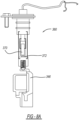
FIG. 7A is a side view of the sensor assembly ofFIG. 6 and shown with the armature disengaged and the switch open; -
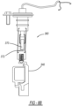
FIG. 7B is a side view of the sensor assembly ofFIG. 7A and shown with the armature engaged and the switch closed; -
FIG. 8A is a side view of the sensor assembly ofFIG. 6 and shown with the armature disengaged and the switch open; -
FIG. 8B is a side view of the sensor assembly ofFIG. 8A and shown with the armature engaged and the switch closed; -
FIG. 9A is a side view of the sensor assembly ofFIG. 8A incorporating a molded connector body and shown with the armature disengaged and the switch open; -
FIG. 9B is a side view of the sensor assembly ofFIG. 9A and shown with the armature engaged and the switch closed; -
FIG. 10 is a top view of the molded connector body of the sensor assembly ofFIG. 9B ; and -
FIG. 11 is a side view of a sensor constructed in accordance to one prior art configuration and shown mounted to a differential case. - One representative embodiment of an electronically actuated locking differential of the type contemplated by the present invention is generally indicated at 10 in
Figures 1 and2 . As shown inFIGS. 1 and2 , the differential 10 includes a gear case, generally indicated at 12, and an end cap (not shown), which may be fastened to thegear case 12 by any suitable fastener, such as by a plurality of bolts (not shown). Thegear case 12 and end cap cooperate with each other to define a gear chamber, generally indicated at 14. The differential 10 is housed within adifferential case 15. Torque input to the differential 10 is typically by an input ring gear (not shown), which may be attached to aflange 16. A gear set is supported within thegear chamber 14 and has at least a pair of input pinion gears 18. The pinion gears 18 are mounted rotatably about a pinion shaft (not shown), which is secured relative to thegear case 12 by any suitable mechanism. The pinion gears 18 are input gears of the gear set and in meshing engagement with a respective pair of left and right side gears, 22 (one side gear shown in the FIGS). The side gears 22 define respective sets of internal,straight splines 26 that are adapted to be in splined engagement with mating external splines on a respective pair of left and right axle shafts (not shown). - A rotation-prevention mechanism, generally indicated at 32, has a generally annular collar member or
lock plate 34 and is disposed entirely within thegear case 12 and operably associated with side gear 22 (the first output gear). Thelock plate 34 is spaced from theside gear 22 and is slidable along the outer surface of theside gear 22. Thelock plate 34 is biased toward the non-actuated, "unlocked" mode by areturn spring 35 such as a wave spring. An electronic actuator, generally indicated at 36, is disposed primarily external to thegear case 12. More specifically, theelectronic actuator 36 is disposed at the end of and about thegear case 12 adjacent side gear 22 (the first output gear). Theelectronic actuator 36 has astator 38 primarily external to thegear case 12. More specifically, thestator 38 is disposed at the end of and about thegear case 12 adjacent to theflange 16. Thestator 38 is stationary and non-rotating relative to thegear case 12. Theelectronic actuator 36 also has an electromagnetic coil, generally indicated at 40, that is disposed in acavity 42 of thestator 38. Theelectromagnetic coil 40 is energized by a pair ofelectrical leads 44 and receives direct current (DC) from a source (not shown). Theelectronic actuator 36 also has an armature, generally indicated at 46, spaced from theelectromagnetic coil 40 to form agap 48 therebetween. Thearmature 46 is mechanically coupled to thelock plate 34 by anannular slip ring 54. - The
actuator 36 includes asensor assembly 60 attached to thedifferential case 15 as will be described herein. Thesensor assembly 60 is used to determine the position of thearmature 46 relative to thestator 38 to interpret the state of the differential 10 in the locked, semi-engaged or unlocked condition. A signal can be sent from thesensor assembly 60 to a display or other vehicle instrumentation such as a cluster 62 (FIG. 1 ) to convey the state of the differential to the driver. The arrangement of thesensor assembly 60 and other configurations described herein isolates thesensor assembly 60 from the severe environment of the armature 46 (vibration, temperature) by moving the sense element or switch from directly contacting thearmature 46 orstator 38. The present invention also limits the modification of the stator eliminating large mass or material additions requiring only a small added element that can be pressed into thestator 38 when needed. - During normal, straight-ahead operation of a vehicle within which the differential 10 is employed, no differentiation occurs between the left and right axle shafts or side gears 22, 24. Therefore, the pinion gears 18 do not rotate relative to the pinion shaft 20. As a result, the
gear case 12, pinion gears 18, and side gears 22, 24 all rotate about an axis of rotation as if thegear case 12, pinion gears 18, and side gears 22, 24 are a solid unit. - When direct current (DC) power is supplied to the
electromagnetic coil 40, magnetic energy is generated within thestator 38 which creates an attractive force between thearmature 46 andstator 38 starting at around 178 N (40 pound-force (lbf)) and ending at around 1112 N (250 Ibf) and causing thearmature 46 to move toward thestator 38. This force is transferred through theslip ring 54 and to thelock plate 34 compressing thereturn spring 35 until thelock plate 34 exerts a required retarding torque on theside gear 22, locking it to thedifferential case 12 and thus locking the LH and RH axle shafts independent of driveline rotation. It should be appreciated in light of the disclosure that the differential 10 allows the LH and RH axle shafts to remain locked independent of vehicle direction. It should also be appreciated in light of the disclosure that the differential 10 is preferred for applications where frequent rock cycles or direction reversals are common such as during snow plowing. It should further be appreciated in light of the disclosure that the differential 10 also enables ease of lock detection by repositioning theslip ring 54 away from theelectromagnetic coil 40, allowing both thestator 38 and thearmature 46 to remain stationary relative to the rotation of the differential 10. - The differential 10 may be controlled manually, wherein a driver of the vehicle manually selects "locked" mode (rather than "unlocked" mode) to operate the differential 10. For example, when, say the vehicle is at rest, the driver simply manually activates a switch or button (not shown), such as a simple momentary-type "on/off" toggle or rocker switch or push button, mounted to a dash or console (not shown) of the vehicle. In this way, an electric circuit (not shown) is closed, thereby turning on current in the circuit and a lamp (not shown) located in or near the toggle switch or push button to indicate to the driver that the differential is actuated. Current flows in the circuit and ultimately to the
electromagnetic coil 48 of the differential 10. The differential 10 then operates in the "locked" mode (i.e., when the vehicle is in first gear or reverse). In this way, thefirst output gear 22 is locked relative to thegear case 12, preventing any further differentiation between thefirst output gear 22 andgear case 12. - By not allowing the
armature 46 to rotate, parasitic losses can be eliminated when the differential 10 is locked because any frictional drag between thearmature 46 and thestator 38 is eliminated. Theelectronic actuator 36 of the present invention creates less heat within the differential 10 due to less friction. Since thearmature 46 is mechanically coupled to thelock plate 34, locking and unlocking of the differential 10 can be detected or sensed based on the axial position of thearmature 46. - With particular reference to
FIG. 3 , thesensor assembly 60 will be further described. Thesensor assembly 60 generally includes aswitch element 70 and a sense element such as amagnet 72. Theswitch element 70 is disposed in asensor housing 74. Themagnet 72 is coupled to thearmature 46. Theswitch element 70 can be a magnetic reed configuration or an active sensor. During operation, theswitch element 70 can change state based on the position of themagnet 72. In this regard, as the armature 46 (carrying the magnet 72) moves left and right and viewed inFIG. 3 , themagnet 72 causes theswitch element 70 to change state. For example, when themagnet 72 is in close proximity to theswitch element 70, theswitch element 70 is in a first state (such as closed) corresponding to armature 46 (and therefore the rotation-prevention mechanism 32) being in the engaged position. When themagnet 72 is caused to be moved away from theswitch element 70, theswitch element 70 is in a second state (such as open) corresponding to the armature 46 (and therefore the rotation-prevention mechanism 32) being in the disengaged position. - The
sensor assembly 60 is connected to thedifferential case 15 by advancing afastener head 80, such as a hex-head bolt into threadable engagement with thedifferential case 15. A compliant member such as an O-ring 82 can be arranged between thesensor housing 74 and thedifferential case 15. The configuration improves upon prior art designs as theswitch element 70 simply mounts to thedifferential case 15. In some examples abore 83 can be formed into thedifferential case 15 for receiving theswitch element 70. Anarm 84 extends from thestator 38. Thearm 84 is used as a reference to align theswitch element 70. During assembly, when thesensor housing 74 andswitch element 70 is inserted into thedifferential case 15 it can be fixtured to thearm 84. In some examples, thesensor housing 74, or parts thereof can be flexible allowing theswitch element 70 to locate relative to thearm 84, such as by referencing a slot feature in the arm prior to tightening thefastener head 80 onto thedifferential case 15. In this regard, the location of theswitch element 70 is known and a reference point is therefore known. Movement of the armature 46 (by way of the magnet 72) can then be used to discern the state of the rotation-prevention mechanism 32. - With particular reference to
FIG. 4A , asensor assembly 160 according to another embodiment of the present invention will be further described. Like components are referenced by like reference numerals increased by 100. Thesensor assembly 160 generally include aswitch element 170 andmagnet 172. Theswitch element 170 and themagnet 172 are both disposed in asensor housing 174. Themagnet 172 is disposed on amagnet mount 176 that is in turn coupled to thearmature 146 by way of adetent mechanism 178. Thedetent mechanism 178 is fixed to thearmature 146 and can include aball 178A and a biasingmember 178B. It is contemplated that theball 178A of thedetent mechanism 178 can nest into arecess 176A provided on themagnet mount 176. An alternate detent mechanism 178' is also shown inFIG. 4C . It is appreciated that other detent mechanisms may be used. Theswitch element 170 can be a magnetic reed configuration or an active sensor. During operation, theswitch element 170 can change state based on the position of themagnet 172. In this regard, as the armature 146 (carrying the magnet 172) moves left and right and viewed inFIG. 4A , themagnet 172 causes theswitch element 170 to change state. For example, when themagnet 172 is in close proximity to theswitch element 170, theswitch element 170 is in a first state (such as closed) corresponding to armature 146 (and therefore the rotation-prevention mechanism 132) being in the engaged position. When themagnet 172 is caused to be moved away from theswitch element 170, theswitch element 170 is in a second state (such as open) corresponding to the armature 146 (and therefore the rotation-prevention mechanism 132) being in the disengaged position. - The
sensor assembly 160 is connected to the differential case by advancing afastener head 180, such as a hex-head bolt into threadable engagement with a threaded bore on the differential case. A compliant member such as an O-ring 182 can be arranged between thesensor housing 174 and the differential case. The configuration improves upon prior art designs as the instant design as theswitch element 170 simply mounts to the differential case. In some examples the bore can be formed into the differential case for receiving theswitch element 170. Anarm 184 extends from thestator 138. Thearm 184 is used as a reference to align thesensor housing 174. During assembly, when thesensor housing 174 andswitch element 170 is inserted into the differential case it can be fixtured to thearm 184. Thesensor housing 174 is flexible allowing it to locate relative to thearm 184, such as by referencing a slot feature in thearm 184 prior to tightening thefastener head 180 onto the differential case. In this regard, the location of theswitch element 170 is known and a reference point is therefore known. Movement of the armature 146 (by way of the magnet 172) can then be used to discern the state of the rotation-prevention mechanism 132. -
FIG. 5 illustrates asensor assembly 260 according to another embodiment of the present invention. Thesensor assembly 260 is constructed similar to thesensor assembly 160 except as identified below. Thesensor assembly 260 is mounted to the differential case by way of a mountingbracket 290. The mountingbracket 290 is coupled to the differential case by abolt 292. One or more O-rings 282 can be arranged around thesensor assembly 260. By using the mountingbracket 290, tangling ofwires 296 can be mitigated. -
FIG. 6 illustrates asensor assembly 360 according to another embodiment of the present invention. Thesensor assembly 360 is constructed similar to thesensor assembly 260 except as identified below. Thesensor assembly 360 incorporates a coupling link ordetent mechanism 378 into thesensor housing 374 of thesensor assembly 360. Specifically, thedetent mechanism 378 is incorporated into themagnet mount 376. The ball of thedetent mechanism 378 can be configured to locate relative to a depression or other locatingfeature 384A on thearm 384. Once thedetent mechanism 378 has coupled to the locatingfeature 384A on thearm 384, thedetent mechanism 378 remains fixed to thearm 384 and thesensor housing 374 allows themagnet mount 376 to swing left and right as viewed in the drawings as a result of thearmature 346 moving between the engaged and disengaged positions. -
FIGS. 7A and7B illustrate one installation configuration for thesensor assembly 360.FIGS. 8A and8B illustrate another configuration for thesensor assembly 360. Both configurations will account for thearmature 346 being engaged or disengaged during installation of thesensor assembly 360. InFIGS. 7A and8A , thearmature 346 is disengaged at installation. InFIG. 7A , and theswitch 370 is in an open position. InFIG. 8A , theswitch 370 is in a closed position. When thearmature 346 moves to the engaged position inFIG. 7B , theswitch 370 closes. When thearmature 346 moves to an engaged position inFIG. 8B , theswitch 370 opens. Regardless, theswitch 370 can be configured to open or closed as desired. The necessary input is a state change where control can determine the rotation-prevention mechanism has changed from one of the locked and unlocked positions to the other of the locked and unlocked positions.FIGS. 9A-10 illustrate another embodiment of thesensor assembly 360 that incorporates a moldedconnector body 398.FIG. 11 illustrates asensor assembly 460 according to a prior art configuration. - The invention has been described in great detail in the foregoing specification, and it is believed that various alterations and modifications of the many aspects of the present invention will become apparent to those having ordinary skill in the art from a reading and understanding of the specification. It is intended that all such alterations and modifications are included in the invention, insofar as they come within the scope of the appended claims.
Claims (14)
- A sensor assembly (60; 160; 260; 360) configured to couple to a differential case (15; 115; 215) of a locking differential (10), the sensor assembly (60) configured to determine a position of an armature (46; 146; 346) in relation to a stator (38; 138), the armature moving relative to the stator between engaged and disengaged positions corresponding to the locking differential being in a locked and unlocked state, the sensor assembly comprising:a sensor housing (74; 174; 374);a switch element (70; 170; 370) disposed in the sensor housing (74; 174; 374); anda sense element (72; 172) that moves with the armature (46; 146; 346);wherein the sensor assembly (60; 160; 260; 360) is configured to change state based on a position of the sense element (72: 172).characterized in thatthe sensor housing (74; 174; 374) is coupled relative to the differential case (15; 115) of the locking differential;the sensor assembly comprises an arm (84; 184) that extends from one of the armature (46; 146; 346) and the stator (38; 138); andthe arm (84; 184; 384) is configured for fixturing the sensor housing (74; 174; 374) to the arm during assembly such that the arm is a reference to align and locate the sensor housing when the sensor housing is inserted into the differential case (15; 115; 215).
- The sensor assembly of claim 1 wherein the sense element (72; 172) is a magnet.
- The sensor assembly of claim 1 wherein the sense element (72; 172) is coupled to the armature (46).
- The sensor assembly of claim 1 wherein the sense element is integrated into the sensor housing (74; 174; 374).
- The sensor assembly of claim 1, wherein the sense element (72; 172) is disposed on a mount (176; 376) and wherein the sensor assembly (60; 160; 260; 360) further comprises a detent mechanism (178; 378) that operably couples the mount relative to the armature (46; 146; 346).
- The sensor assembly of claim 5 wherein the detent mechanism (178; 378) is fixed to the armature (46; 146; 346) or to the mount (176; 376).
- The sensor assembly of claim 6 wherein the detent mechanism (178; 378) is fixed to the mount (176; 376) and includes a ball (178A) that locates relative to a depression (384A) formed on the arm which extends from the stator (38; 138).
- The sensor assembly of claim 4 wherein the sensor housing (74; 174; 374) is configured to flex during movement of the armature (46; 146; 346) between the engaged and disengaged positions.
- The sensor assembly of claim 1 wherein the sensor housing (74; 174; 374) further comprises a molded connector body (398).
- The sensor assembly of claim 1 wherein the sensor assembly (60; 160; 260; 360) is coupled to the differential case (15; 115; 215) by a fastener, wherein optionally the fastener is a threaded fastener and the sensor assembly is connected to the differential case by the threaded fastener advanced into a complementary threaded bore (183) defined in the differential case (115).
- The sensor assembly of claim 1 wherein the sensor assembly (60; 160; 260; 360) for communicating a signal to vehicle instrumentation to convey a state of the differential.
- A method of installing a sensor assembly (60; 160; 260; 360) according to claim 1 relative to an assembled locking differential (10), the assembled locking differential having a differential case (15; 115; 215), a rotation prevention mechanism (32; 132), and an actuator (36) having an armature (46; 146; 346) and a stator (38; 138), the method comprising:forming a bore (83) in the differential case (15; 115; 215) configured to receive the sensor assembly (60; 160; 260; 360);advancing the sensor assembly (60; 160; 260; 360) through the bore (83) formed in the differential case (15; 115; 215);locating a switch element (70; 170; 370) of the sensor assembly relative to a sense element (72; 172) disposed on the armature by fixturing a portion of the sensor assembly (60; 160; 260; 360) to an arm (84; 184) extending from one of the armature (46; 146; 346) and the stator (38; 138); andfixing the sensor assembly (60; 160; 260; 360) to the differential case (15; 115; 215).
- The method of claim 12, further comprising:
coupling a magnet mount (176; 376) to the armature by locating a ball (178A) of a detent mechanism (178; 378) disposed on the armature (46; 146; 346) into a recess (176A) provided on the detent mechanism. - The method of claim 12 wherein fixing the sensor assembly comprises threadably tightening a fastener relative to a complementary threaded bore (183) defined in the differential case (15; 115; 215).
Applications Claiming Priority (2)
| Application Number | Priority Date | Filing Date | Title |
|---|---|---|---|
| US201762520942P | 2017-06-16 | 2017-06-16 | |
| PCT/US2018/037788 WO2018232262A1 (en) | 2017-06-16 | 2018-06-15 | Differential lock/unlock position detection |
Publications (3)
| Publication Number | Publication Date |
|---|---|
| EP3638924A1 EP3638924A1 (en) | 2020-04-22 |
| EP3638924A4 EP3638924A4 (en) | 2021-01-20 |
| EP3638924B1 true EP3638924B1 (en) | 2024-08-28 |
Family
ID=64659738
Family Applications (1)
| Application Number | Title | Priority Date | Filing Date |
|---|---|---|---|
| EP18818671.2A Active EP3638924B1 (en) | 2017-06-16 | 2018-06-15 | Differential lock/unlock position detection |
Country Status (4)
| Country | Link |
|---|---|
| US (2) | US11585421B2 (en) |
| EP (1) | EP3638924B1 (en) |
| CN (1) | CN111033088B (en) |
| WO (1) | WO2018232262A1 (en) |
Families Citing this family (8)
| Publication number | Priority date | Publication date | Assignee | Title |
|---|---|---|---|---|
| US12129915B2 (en) | 2021-02-04 | 2024-10-29 | Eaton Intelligent Power Limited | Locking differential assembly |
| KR20230154211A (en) | 2021-03-05 | 2023-11-07 | 이턴 인텔리전트 파워 리미티드 | Electronic locking differential with position sensor |
| WO2023041199A1 (en) * | 2021-09-15 | 2023-03-23 | Eaton Intelligent Power Limited | Lock detection mechanism for electronic locking differential |
| CN114110122B (en) * | 2021-11-11 | 2023-09-19 | 精进电动科技股份有限公司 | a differential system |
| US12404921B2 (en) | 2022-01-10 | 2025-09-02 | Eaton Intelligent Power Limited | Systems and devices for controlling sensing plate lash in a lock detection mechanism for electronic locking differentials |
| DE112023003531T5 (en) * | 2022-08-24 | 2025-08-28 | Eaton Intelligent Power Limited | Systems and methods for coupling a locking plate and an actuator |
| WO2025126145A1 (en) * | 2023-12-14 | 2025-06-19 | Eaton Intelligent Power Limited | Electronic locking differential |
| US12179834B1 (en) * | 2024-05-14 | 2024-12-31 | Deere & Company | Work machine with a differential protection system and method |
Family Cites Families (13)
| Publication number | Priority date | Publication date | Assignee | Title |
|---|---|---|---|---|
| JPS6148648A (en) * | 1984-08-10 | 1986-03-10 | Toyota Motor Corp | Operating mechanism of transmission gear for vehicle |
| US6165095A (en) * | 1998-02-25 | 2000-12-26 | Auburn Gear, Inc. | Apparatus and method for demagnetizing a controllable electromagnetically actuated differential |
| US20040132572A1 (en) * | 2003-01-02 | 2004-07-08 | Eaton Corporation | Lock detection sensor |
| US6958030B2 (en) * | 2003-09-29 | 2005-10-25 | American Axle & Manufacturing, Inc. | Electromagnetic locking differential assembly |
| JP4538419B2 (en) * | 2006-02-20 | 2010-09-08 | Gknドライブラインジャパン株式会社 | Differential device |
| US7602271B2 (en) * | 2006-08-21 | 2009-10-13 | American Axle & Manufacturing, Inc. | Electronically actuated apparatus using solenoid actuator with integrated sensor |
| US7837585B2 (en) * | 2006-11-27 | 2010-11-23 | American Axle & Manufacturing, Inc. | Linear actuator with position sensing system |
| US7572202B2 (en) * | 2007-01-31 | 2009-08-11 | American Axle & Manufacturing, Inc. | Electronic locking differential with direct locking state detection system |
| DE102009056088B4 (en) * | 2009-11-30 | 2011-10-06 | Gkn Driveline International Gmbh | Differential assembly and drive assembly with a differential assembly |
| JP6218813B2 (en) * | 2012-05-23 | 2017-10-25 | イートン コーポレーションEaton Corporation | Electronically actuated locking differential with non-rotating stator and armature |
| WO2015056330A1 (en) * | 2013-10-17 | 2015-04-23 | Gkn ドライブライン ジャパン株式会社 | Clutch device and differential device with reduced friction loss |
| EP3332223B1 (en) * | 2015-08-07 | 2019-07-10 | Dana Automotive Systems Group, LLC | Wireless system for determining displacement of spinning components |
| US9989140B2 (en) * | 2016-03-02 | 2018-06-05 | Jtekt Corporation | Power transmission interrupting device and limited-slip differential |
-
2018
- 2018-06-15 CN CN201880050326.1A patent/CN111033088B/en active Active
- 2018-06-15 WO PCT/US2018/037788 patent/WO2018232262A1/en not_active Ceased
- 2018-06-15 EP EP18818671.2A patent/EP3638924B1/en active Active
-
2019
- 2019-12-16 US US16/714,957 patent/US11585421B2/en active Active
-
2023
- 2023-02-08 US US18/107,155 patent/US12129917B2/en active Active
Also Published As
| Publication number | Publication date |
|---|---|
| US11585421B2 (en) | 2023-02-21 |
| WO2018232262A1 (en) | 2018-12-20 |
| US20230184314A1 (en) | 2023-06-15 |
| CN111033088B (en) | 2024-05-31 |
| EP3638924A4 (en) | 2021-01-20 |
| CN111033088A (en) | 2020-04-17 |
| US20200116245A1 (en) | 2020-04-16 |
| EP3638924A1 (en) | 2020-04-22 |
| US12129917B2 (en) | 2024-10-29 |
Similar Documents
| Publication | Publication Date | Title |
|---|---|---|
| EP3638924B1 (en) | Differential lock/unlock position detection | |
| EP2852780B1 (en) | Electronically actuated locking differential having non-rotating stator and armature | |
| US11396935B2 (en) | Differential having armature position detection | |
| KR101382053B1 (en) | Lockable differential with locking state detection system | |
| EP3807599B1 (en) | Differential having armature position detection | |
| RU2731585C1 (en) | Locked differential in assembly | |
| EP2002155B1 (en) | Two wire dual sensor differential locking state detection system | |
| US11378168B2 (en) | Direct acting electronic locking differential | |
| US12359721B2 (en) | Systems and methods for a rotary disconnect | |
| US10267400B2 (en) | Differential apparatus | |
| US20170291492A1 (en) | Differential apparatus | |
| WO2020088801A1 (en) | Anti-rotation features for direct acting electronic locking differential | |
| JP2015172412A (en) | Electromagnetic clutch control device | |
| CN117980630A (en) | Lock detection mechanism for electronically locking differentials | |
| CN118541555A (en) | System and apparatus for controlling sense plate clearance in a lock detection mechanism for an electronically locking differential | |
| KR20230145443A (en) | Transmission system with coupling device | |
| BR112020025514B1 (en) | Position detection device configured for use with a locking differential. |
Legal Events
| Date | Code | Title | Description |
|---|---|---|---|
| STAA | Information on the status of an ep patent application or granted ep patent |
Free format text: STATUS: THE INTERNATIONAL PUBLICATION HAS BEEN MADE |
|
| PUAI | Public reference made under article 153(3) epc to a published international application that has entered the european phase |
Free format text: ORIGINAL CODE: 0009012 |
|
| STAA | Information on the status of an ep patent application or granted ep patent |
Free format text: STATUS: REQUEST FOR EXAMINATION WAS MADE |
|
| 17P | Request for examination filed |
Effective date: 20200114 |
|
| AK | Designated contracting states |
Kind code of ref document: A1 Designated state(s): AL AT BE BG CH CY CZ DE DK EE ES FI FR GB GR HR HU IE IS IT LI LT LU LV MC MK MT NL NO PL PT RO RS SE SI SK SM TR |
|
| AX | Request for extension of the european patent |
Extension state: BA ME |
|
| DAV | Request for validation of the european patent (deleted) | ||
| DAX | Request for extension of the european patent (deleted) | ||
| A4 | Supplementary search report drawn up and despatched |
Effective date: 20201222 |
|
| RIC1 | Information provided on ipc code assigned before grant |
Ipc: F16H 48/06 20060101ALI20201216BHEP Ipc: F16H 48/30 20120101ALI20201216BHEP Ipc: B60K 17/16 20060101ALI20201216BHEP Ipc: F16H 48/34 20120101AFI20201216BHEP Ipc: F16H 48/20 20120101ALI20201216BHEP |
|
| STAA | Information on the status of an ep patent application or granted ep patent |
Free format text: STATUS: EXAMINATION IS IN PROGRESS |
|
| 17Q | First examination report despatched |
Effective date: 20211122 |
|
| P01 | Opt-out of the competence of the unified patent court (upc) registered |
Effective date: 20230521 |
|
| GRAP | Despatch of communication of intention to grant a patent |
Free format text: ORIGINAL CODE: EPIDOSNIGR1 |
|
| STAA | Information on the status of an ep patent application or granted ep patent |
Free format text: STATUS: GRANT OF PATENT IS INTENDED |
|
| INTG | Intention to grant announced |
Effective date: 20240321 |
|
| GRAS | Grant fee paid |
Free format text: ORIGINAL CODE: EPIDOSNIGR3 |
|
| GRAA | (expected) grant |
Free format text: ORIGINAL CODE: 0009210 |
|
| STAA | Information on the status of an ep patent application or granted ep patent |
Free format text: STATUS: THE PATENT HAS BEEN GRANTED |
|
| AK | Designated contracting states |
Kind code of ref document: B1 Designated state(s): AL AT BE BG CH CY CZ DE DK EE ES FI FR GB GR HR HU IE IS IT LI LT LU LV MC MK MT NL NO PL PT RO RS SE SI SK SM TR |
|
| REG | Reference to a national code |
Ref country code: GB Ref legal event code: FG4D |
|
| REG | Reference to a national code |
Ref country code: CH Ref legal event code: EP |
|
| REG | Reference to a national code |
Ref country code: DE Ref legal event code: R096 Ref document number: 602018073711 Country of ref document: DE |
|
| REG | Reference to a national code |
Ref country code: IE Ref legal event code: FG4D |
|
| REG | Reference to a national code |
Ref country code: LT Ref legal event code: MG9D |
|
| PG25 | Lapsed in a contracting state [announced via postgrant information from national office to epo] |
Ref country code: NO Free format text: LAPSE BECAUSE OF FAILURE TO SUBMIT A TRANSLATION OF THE DESCRIPTION OR TO PAY THE FEE WITHIN THE PRESCRIBED TIME-LIMIT Effective date: 20241128 |
|
| REG | Reference to a national code |
Ref country code: AT Ref legal event code: MK05 Ref document number: 1718257 Country of ref document: AT Kind code of ref document: T Effective date: 20240828 |
|
| PG25 | Lapsed in a contracting state [announced via postgrant information from national office to epo] |
Ref country code: NL Free format text: LAPSE BECAUSE OF FAILURE TO SUBMIT A TRANSLATION OF THE DESCRIPTION OR TO PAY THE FEE WITHIN THE PRESCRIBED TIME-LIMIT Effective date: 20240828 Ref country code: PT Free format text: LAPSE BECAUSE OF FAILURE TO SUBMIT A TRANSLATION OF THE DESCRIPTION OR TO PAY THE FEE WITHIN THE PRESCRIBED TIME-LIMIT Effective date: 20241230 Ref country code: PL Free format text: LAPSE BECAUSE OF FAILURE TO SUBMIT A TRANSLATION OF THE DESCRIPTION OR TO PAY THE FEE WITHIN THE PRESCRIBED TIME-LIMIT Effective date: 20240828 Ref country code: GR Free format text: LAPSE BECAUSE OF FAILURE TO SUBMIT A TRANSLATION OF THE DESCRIPTION OR TO PAY THE FEE WITHIN THE PRESCRIBED TIME-LIMIT Effective date: 20241129 Ref country code: FI Free format text: LAPSE BECAUSE OF FAILURE TO SUBMIT A TRANSLATION OF THE DESCRIPTION OR TO PAY THE FEE WITHIN THE PRESCRIBED TIME-LIMIT Effective date: 20240828 |
|
| PG25 | Lapsed in a contracting state [announced via postgrant information from national office to epo] |
Ref country code: BG Free format text: LAPSE BECAUSE OF FAILURE TO SUBMIT A TRANSLATION OF THE DESCRIPTION OR TO PAY THE FEE WITHIN THE PRESCRIBED TIME-LIMIT Effective date: 20240828 |
|
| PG25 | Lapsed in a contracting state [announced via postgrant information from national office to epo] |
Ref country code: LV Free format text: LAPSE BECAUSE OF FAILURE TO SUBMIT A TRANSLATION OF THE DESCRIPTION OR TO PAY THE FEE WITHIN THE PRESCRIBED TIME-LIMIT Effective date: 20240828 |
|
| REG | Reference to a national code |
Ref country code: NL Ref legal event code: MP Effective date: 20240828 |
|
| PG25 | Lapsed in a contracting state [announced via postgrant information from national office to epo] |
Ref country code: IS Free format text: LAPSE BECAUSE OF FAILURE TO SUBMIT A TRANSLATION OF THE DESCRIPTION OR TO PAY THE FEE WITHIN THE PRESCRIBED TIME-LIMIT Effective date: 20241228 Ref country code: AT Free format text: LAPSE BECAUSE OF FAILURE TO SUBMIT A TRANSLATION OF THE DESCRIPTION OR TO PAY THE FEE WITHIN THE PRESCRIBED TIME-LIMIT Effective date: 20240828 |
|
| PG25 | Lapsed in a contracting state [announced via postgrant information from national office to epo] |
Ref country code: HR Free format text: LAPSE BECAUSE OF FAILURE TO SUBMIT A TRANSLATION OF THE DESCRIPTION OR TO PAY THE FEE WITHIN THE PRESCRIBED TIME-LIMIT Effective date: 20240828 |
|
| PG25 | Lapsed in a contracting state [announced via postgrant information from national office to epo] |
Ref country code: ES Free format text: LAPSE BECAUSE OF FAILURE TO SUBMIT A TRANSLATION OF THE DESCRIPTION OR TO PAY THE FEE WITHIN THE PRESCRIBED TIME-LIMIT Effective date: 20240828 Ref country code: RS Free format text: LAPSE BECAUSE OF FAILURE TO SUBMIT A TRANSLATION OF THE DESCRIPTION OR TO PAY THE FEE WITHIN THE PRESCRIBED TIME-LIMIT Effective date: 20241128 |
|
| PG25 | Lapsed in a contracting state [announced via postgrant information from national office to epo] |
Ref country code: RS Free format text: LAPSE BECAUSE OF FAILURE TO SUBMIT A TRANSLATION OF THE DESCRIPTION OR TO PAY THE FEE WITHIN THE PRESCRIBED TIME-LIMIT Effective date: 20241128 Ref country code: PT Free format text: LAPSE BECAUSE OF FAILURE TO SUBMIT A TRANSLATION OF THE DESCRIPTION OR TO PAY THE FEE WITHIN THE PRESCRIBED TIME-LIMIT Effective date: 20241230 Ref country code: PL Free format text: LAPSE BECAUSE OF FAILURE TO SUBMIT A TRANSLATION OF THE DESCRIPTION OR TO PAY THE FEE WITHIN THE PRESCRIBED TIME-LIMIT Effective date: 20240828 Ref country code: NO Free format text: LAPSE BECAUSE OF FAILURE TO SUBMIT A TRANSLATION OF THE DESCRIPTION OR TO PAY THE FEE WITHIN THE PRESCRIBED TIME-LIMIT Effective date: 20241128 Ref country code: NL Free format text: LAPSE BECAUSE OF FAILURE TO SUBMIT A TRANSLATION OF THE DESCRIPTION OR TO PAY THE FEE WITHIN THE PRESCRIBED TIME-LIMIT Effective date: 20240828 Ref country code: LV Free format text: LAPSE BECAUSE OF FAILURE TO SUBMIT A TRANSLATION OF THE DESCRIPTION OR TO PAY THE FEE WITHIN THE PRESCRIBED TIME-LIMIT Effective date: 20240828 Ref country code: IS Free format text: LAPSE BECAUSE OF FAILURE TO SUBMIT A TRANSLATION OF THE DESCRIPTION OR TO PAY THE FEE WITHIN THE PRESCRIBED TIME-LIMIT Effective date: 20241228 Ref country code: HR Free format text: LAPSE BECAUSE OF FAILURE TO SUBMIT A TRANSLATION OF THE DESCRIPTION OR TO PAY THE FEE WITHIN THE PRESCRIBED TIME-LIMIT Effective date: 20240828 Ref country code: GR Free format text: LAPSE BECAUSE OF FAILURE TO SUBMIT A TRANSLATION OF THE DESCRIPTION OR TO PAY THE FEE WITHIN THE PRESCRIBED TIME-LIMIT Effective date: 20241129 Ref country code: FI Free format text: LAPSE BECAUSE OF FAILURE TO SUBMIT A TRANSLATION OF THE DESCRIPTION OR TO PAY THE FEE WITHIN THE PRESCRIBED TIME-LIMIT Effective date: 20240828 Ref country code: ES Free format text: LAPSE BECAUSE OF FAILURE TO SUBMIT A TRANSLATION OF THE DESCRIPTION OR TO PAY THE FEE WITHIN THE PRESCRIBED TIME-LIMIT Effective date: 20240828 Ref country code: BG Free format text: LAPSE BECAUSE OF FAILURE TO SUBMIT A TRANSLATION OF THE DESCRIPTION OR TO PAY THE FEE WITHIN THE PRESCRIBED TIME-LIMIT Effective date: 20240828 Ref country code: AT Free format text: LAPSE BECAUSE OF FAILURE TO SUBMIT A TRANSLATION OF THE DESCRIPTION OR TO PAY THE FEE WITHIN THE PRESCRIBED TIME-LIMIT Effective date: 20240828 |
|
| PG25 | Lapsed in a contracting state [announced via postgrant information from national office to epo] |
Ref country code: SM Free format text: LAPSE BECAUSE OF FAILURE TO SUBMIT A TRANSLATION OF THE DESCRIPTION OR TO PAY THE FEE WITHIN THE PRESCRIBED TIME-LIMIT Effective date: 20240828 Ref country code: DK Free format text: LAPSE BECAUSE OF FAILURE TO SUBMIT A TRANSLATION OF THE DESCRIPTION OR TO PAY THE FEE WITHIN THE PRESCRIBED TIME-LIMIT Effective date: 20240828 Ref country code: RO Free format text: LAPSE BECAUSE OF FAILURE TO SUBMIT A TRANSLATION OF THE DESCRIPTION OR TO PAY THE FEE WITHIN THE PRESCRIBED TIME-LIMIT Effective date: 20240828 |
|
| PG25 | Lapsed in a contracting state [announced via postgrant information from national office to epo] |
Ref country code: EE Free format text: LAPSE BECAUSE OF FAILURE TO SUBMIT A TRANSLATION OF THE DESCRIPTION OR TO PAY THE FEE WITHIN THE PRESCRIBED TIME-LIMIT Effective date: 20240828 |
|
| PG25 | Lapsed in a contracting state [announced via postgrant information from national office to epo] |
Ref country code: CZ Free format text: LAPSE BECAUSE OF FAILURE TO SUBMIT A TRANSLATION OF THE DESCRIPTION OR TO PAY THE FEE WITHIN THE PRESCRIBED TIME-LIMIT Effective date: 20240828 |
|
| PG25 | Lapsed in a contracting state [announced via postgrant information from national office to epo] |
Ref country code: IT Free format text: LAPSE BECAUSE OF FAILURE TO SUBMIT A TRANSLATION OF THE DESCRIPTION OR TO PAY THE FEE WITHIN THE PRESCRIBED TIME-LIMIT Effective date: 20240828 Ref country code: SK Free format text: LAPSE BECAUSE OF FAILURE TO SUBMIT A TRANSLATION OF THE DESCRIPTION OR TO PAY THE FEE WITHIN THE PRESCRIBED TIME-LIMIT Effective date: 20240828 |
|
| REG | Reference to a national code |
Ref country code: DE Ref legal event code: R097 Ref document number: 602018073711 Country of ref document: DE |
|
| PLBE | No opposition filed within time limit |
Free format text: ORIGINAL CODE: 0009261 |
|
| STAA | Information on the status of an ep patent application or granted ep patent |
Free format text: STATUS: NO OPPOSITION FILED WITHIN TIME LIMIT |
|
| PGFP | Annual fee paid to national office [announced via postgrant information from national office to epo] |
Ref country code: DE Payment date: 20250520 Year of fee payment: 8 |
|
| 26N | No opposition filed |
Effective date: 20250530 |
|
| PG25 | Lapsed in a contracting state [announced via postgrant information from national office to epo] |
Ref country code: SE Free format text: LAPSE BECAUSE OF FAILURE TO SUBMIT A TRANSLATION OF THE DESCRIPTION OR TO PAY THE FEE WITHIN THE PRESCRIBED TIME-LIMIT Effective date: 20240828 |
|
| REG | Reference to a national code |
Ref country code: CH Ref legal event code: H13 Free format text: ST27 STATUS EVENT CODE: U-0-0-H10-H13 (AS PROVIDED BY THE NATIONAL OFFICE) Effective date: 20260127 |
|
| PG25 | Lapsed in a contracting state [announced via postgrant information from national office to epo] |
Ref country code: MC Free format text: LAPSE BECAUSE OF FAILURE TO SUBMIT A TRANSLATION OF THE DESCRIPTION OR TO PAY THE FEE WITHIN THE PRESCRIBED TIME-LIMIT Effective date: 20240828 |
|
| PG25 | Lapsed in a contracting state [announced via postgrant information from national office to epo] |
Ref country code: LU Free format text: LAPSE BECAUSE OF NON-PAYMENT OF DUE FEES Effective date: 20250615 |
|
| GBPC | Gb: european patent ceased through non-payment of renewal fee |
Effective date: 20250615 |
|
| REG | Reference to a national code |
Ref country code: BE Ref legal event code: MM Effective date: 20250630 |
|
| PG25 | Lapsed in a contracting state [announced via postgrant information from national office to epo] |
Ref country code: GB Free format text: LAPSE BECAUSE OF NON-PAYMENT OF DUE FEES Effective date: 20250615 |
|
| PG25 | Lapsed in a contracting state [announced via postgrant information from national office to epo] |
Ref country code: IE Free format text: LAPSE BECAUSE OF NON-PAYMENT OF DUE FEES Effective date: 20250615 |
|
| PG25 | Lapsed in a contracting state [announced via postgrant information from national office to epo] |
Ref country code: BE Free format text: LAPSE BECAUSE OF NON-PAYMENT OF DUE FEES Effective date: 20250630 |
|
| PG25 | Lapsed in a contracting state [announced via postgrant information from national office to epo] |
Ref country code: FR Free format text: LAPSE BECAUSE OF NON-PAYMENT OF DUE FEES Effective date: 20250630 |
|
| PG25 | Lapsed in a contracting state [announced via postgrant information from national office to epo] |
Ref country code: CH Free format text: LAPSE BECAUSE OF NON-PAYMENT OF DUE FEES Effective date: 20250630 |