EP3638916B1 - Hybrid apparatus for controlling the rotation of a fan for cooling the cooling fluid of a vehicle - Google Patents
Hybrid apparatus for controlling the rotation of a fan for cooling the cooling fluid of a vehicle Download PDFInfo
- Publication number
- EP3638916B1 EP3638916B1 EP18738378.1A EP18738378A EP3638916B1 EP 3638916 B1 EP3638916 B1 EP 3638916B1 EP 18738378 A EP18738378 A EP 18738378A EP 3638916 B1 EP3638916 B1 EP 3638916B1
- Authority
- EP
- European Patent Office
- Prior art keywords
- fan
- electric motor
- stator
- rotation
- rotor
- Prior art date
- Legal status (The legal status is an assumption and is not a legal conclusion. Google has not performed a legal analysis and makes no representation as to the accuracy of the status listed.)
- Active
Links
Images

Classifications
-
- F—MECHANICAL ENGINEERING; LIGHTING; HEATING; WEAPONS; BLASTING
- F01—MACHINES OR ENGINES IN GENERAL; ENGINE PLANTS IN GENERAL; STEAM ENGINES
- F01P—COOLING OF MACHINES OR ENGINES IN GENERAL; COOLING OF INTERNAL-COMBUSTION ENGINES
- F01P5/00—Pumping cooling-air or liquid coolants
- F01P5/02—Pumping cooling-air; Arrangements of cooling-air pumps, e.g. fans or blowers
- F01P5/04—Pump-driving arrangements
- F01P5/043—Pump reversing arrangements
-
- F—MECHANICAL ENGINEERING; LIGHTING; HEATING; WEAPONS; BLASTING
- F01—MACHINES OR ENGINES IN GENERAL; ENGINE PLANTS IN GENERAL; STEAM ENGINES
- F01P—COOLING OF MACHINES OR ENGINES IN GENERAL; COOLING OF INTERNAL-COMBUSTION ENGINES
- F01P7/00—Controlling of coolant flow
- F01P7/02—Controlling of coolant flow the coolant being cooling-air
- F01P7/04—Controlling of coolant flow the coolant being cooling-air by varying pump speed, e.g. by changing pump-drive gear ratio
- F01P7/048—Controlling of coolant flow the coolant being cooling-air by varying pump speed, e.g. by changing pump-drive gear ratio using electrical drives
-
- F—MECHANICAL ENGINEERING; LIGHTING; HEATING; WEAPONS; BLASTING
- F01—MACHINES OR ENGINES IN GENERAL; ENGINE PLANTS IN GENERAL; STEAM ENGINES
- F01P—COOLING OF MACHINES OR ENGINES IN GENERAL; COOLING OF INTERNAL-COMBUSTION ENGINES
- F01P7/00—Controlling of coolant flow
- F01P7/02—Controlling of coolant flow the coolant being cooling-air
- F01P7/08—Controlling of coolant flow the coolant being cooling-air by cutting in or out of pumps
- F01P7/081—Controlling of coolant flow the coolant being cooling-air by cutting in or out of pumps using clutches, e.g. electro-magnetic or induction clutches
- F01P7/082—Controlling of coolant flow the coolant being cooling-air by cutting in or out of pumps using clutches, e.g. electro-magnetic or induction clutches using friction clutches
- F01P7/084—Controlling of coolant flow the coolant being cooling-air by cutting in or out of pumps using clutches, e.g. electro-magnetic or induction clutches using friction clutches actuated electromagnetically
-
- F—MECHANICAL ENGINEERING; LIGHTING; HEATING; WEAPONS; BLASTING
- F04—POSITIVE - DISPLACEMENT MACHINES FOR LIQUIDS; PUMPS FOR LIQUIDS OR ELASTIC FLUIDS
- F04D—NON-POSITIVE-DISPLACEMENT PUMPS
- F04D25/00—Pumping installations or systems
- F04D25/02—Units comprising pumps and their driving means
-
- F—MECHANICAL ENGINEERING; LIGHTING; HEATING; WEAPONS; BLASTING
- F04—POSITIVE - DISPLACEMENT MACHINES FOR LIQUIDS; PUMPS FOR LIQUIDS OR ELASTIC FLUIDS
- F04D—NON-POSITIVE-DISPLACEMENT PUMPS
- F04D25/00—Pumping installations or systems
- F04D25/02—Units comprising pumps and their driving means
- F04D25/026—Units comprising pumps and their driving means with a magnetic coupling
-
- F—MECHANICAL ENGINEERING; LIGHTING; HEATING; WEAPONS; BLASTING
- F04—POSITIVE - DISPLACEMENT MACHINES FOR LIQUIDS; PUMPS FOR LIQUIDS OR ELASTIC FLUIDS
- F04D—NON-POSITIVE-DISPLACEMENT PUMPS
- F04D25/00—Pumping installations or systems
- F04D25/02—Units comprising pumps and their driving means
- F04D25/06—Units comprising pumps and their driving means the pump being electrically driven
- F04D25/0606—Units comprising pumps and their driving means the pump being electrically driven the electric motor being specially adapted for integration in the pump
- F04D25/0613—Units comprising pumps and their driving means the pump being electrically driven the electric motor being specially adapted for integration in the pump the electric motor being of the inside-out type, i.e. the rotor is arranged radially outside a central stator
- F04D25/062—Details of the bearings
-
- F—MECHANICAL ENGINEERING; LIGHTING; HEATING; WEAPONS; BLASTING
- F04—POSITIVE - DISPLACEMENT MACHINES FOR LIQUIDS; PUMPS FOR LIQUIDS OR ELASTIC FLUIDS
- F04D—NON-POSITIVE-DISPLACEMENT PUMPS
- F04D25/00—Pumping installations or systems
- F04D25/02—Units comprising pumps and their driving means
- F04D25/06—Units comprising pumps and their driving means the pump being electrically driven
- F04D25/068—Mechanical details of the pump control unit
-
- F—MECHANICAL ENGINEERING; LIGHTING; HEATING; WEAPONS; BLASTING
- F16—ENGINEERING ELEMENTS AND UNITS; GENERAL MEASURES FOR PRODUCING AND MAINTAINING EFFECTIVE FUNCTIONING OF MACHINES OR INSTALLATIONS; THERMAL INSULATION IN GENERAL
- F16D—COUPLINGS FOR TRANSMITTING ROTATION; CLUTCHES; BRAKES
- F16D27/00—Magnetically- or electrically- actuated clutches; Control or electric circuits therefor
- F16D27/10—Magnetically- or electrically- actuated clutches; Control or electric circuits therefor with an electromagnet not rotating with a clutching member, i.e. without collecting rings
- F16D27/108—Magnetically- or electrically- actuated clutches; Control or electric circuits therefor with an electromagnet not rotating with a clutching member, i.e. without collecting rings with axially movable clutching members
- F16D27/112—Magnetically- or electrically- actuated clutches; Control or electric circuits therefor with an electromagnet not rotating with a clutching member, i.e. without collecting rings with axially movable clutching members with flat friction surfaces, e.g. discs
-
- F—MECHANICAL ENGINEERING; LIGHTING; HEATING; WEAPONS; BLASTING
- F04—POSITIVE - DISPLACEMENT MACHINES FOR LIQUIDS; PUMPS FOR LIQUIDS OR ELASTIC FLUIDS
- F04D—NON-POSITIVE-DISPLACEMENT PUMPS
- F04D29/00—Details, component parts, or accessories
- F04D29/05—Shafts or bearings, or assemblies thereof, specially adapted for elastic fluid pumps
- F04D29/056—Bearings
- F04D29/059—Roller bearings
Definitions
- the present invention relates to a hybrid apparatus for controlling the rotation of fans for cooling the cooling fluid contained in the radiator of motor vehicles.
- said fan must be rotated only when the cooling fluid reaches a certain predefined temperature detected by means of a thermostat which operates an electromagnetic friction coupling, closing of which starts rotation of the fan.
- said apparatus comprising an electromagnetically controlled friction coupling arranged between the fan and means for generating the rotational movement which are connected to the shaft of the combustion engine, as well as electrical devices able to control the rotation of the fan independently of the combustion engine shaft and with a programmable number of revolutions.
- WO2011006595 describes an apparatus according to the preamble of Claim 1, wherein the rotational movement is received from a coaxial shaft arranged in a position radially on the inside of the friction coupling and the electric motor.
- the positioning of any electronic drive for the electrical devices does not create any problems since the fixed part of the apparatus is arranged in a radially outer position and the stator of the electric motor fixed to it is easily accessible.
- This apparatus however has the drawback that it has an excessively large volume in the radial direction which is not always compatible with the dimensions of the engine compartment of vehicles such as vans and lorries.
- the known apparatus are unable to solve the problem of blockage of the radiator cells and therefore lack of cooling of the fluid contained inside said radiator.
- the technical problem which is posed, therefore, is that of providing an apparatus for controlling the rotation of fans for cooling the cooling fluid of vehicles, which is able to solve or at least partially overcome the aforementioned problems of the prior art.
- this apparatus should have small dimensions, in particular in the radial direction.
- a further desirable feature is that the apparatus should be easy and inepxensive to produce and assemble and be able to be easily installed at any user location using normal standardized connection means.
- the apparatus for controlling the rotation of the fan according to the invention is designed such that:
- an electromagnetic friction coupling 10 which comprises:
- the bell member 1a is also joined together with the rotor 22 of an electric motor 20, the stator 21 of which is mounted on a second support flange 40 fastened to the front end of the support sleeve 3;
- the second flange 40 has a shaped radial extension 41 to which the stator 21 is fixed by means of screw-type fixing means 42;
- the radial extension 41 defines a coaxial seat 43 for housing an electronic drive and control unit 30 of the electric motor 20, which is connected by means of cables 32 passing through the flange 40 to the electric motor 20 and supplied with power via the electrical connections 31.
- the fan 1 can be connected by means of the bell member 1a both to the electromagnetic friction coupling 10 and to the electric motor 20 which is current-controlled by means of the associated control unit 30.
- the electronic drive and control unit 130 of the electric motor 20 is arranged in an axially inner position coaxial with the stator 21 of the electric motor and preferably concentric therewith.
- the second flange 140 supports the electronic drive unit 130 and the stator 21 in a radially inner position and radially outer position, respectively.
- the second flange 140 may comprise a radial extension 141 to which the stator 21 is fixed by means of through-screws 142 engaging with a corresponding female thread of the radial extension 141.
- the electric motor is arranged in a position axially on the outside of the means for receiving the movement 11c;11e and/or of the electromagnetic friction coupling, which allows the radial dimensions of the apparatus to be further reduced.
- operation of the fan is dependent on the activation of one or the other of the two movement transmission/generating devices:
- the fan rotates in the direction - anticlockwise in the example of the Figure - such as to draw air from the outside towards the surface of the radiator arranged in front of the fan with respect to the direction of travel of the vehicle;
- the electric motor 20 may be powered with opposite currents so as to cause a rotation of the rotor 22 of the electric motor and therefore the fan 1 in the direction - clockwise in the example - of a thrusting force of the air acting in the direction of travel of the vehicle so that, crossing the radiator from the inside towards the outside, the dirt which has accumulated on the surface of the radiator during the cooling cycles is removed, thus restoring the full functionality of the radiator which has been reduced in the meantime owing to the dirt.
- the apparatus according to the invention is able to cause operation of the fan both so as to cool the cooling fluid contained in the radiator and, if convenient or required, so as to perform cleaning of the surface of the said radiator, which cleaning may take place also during normal travel of the vehicle and therefore without the vehicle stoppage downtime resulting from the need to cool the radiator in order to be able to access it manually for cleaning thereof.
- the second support flange joined together with the sleeve 3 allows the electronic drive and control unit of the electric motor to be housed radially on the inside of the bell member 1a of the apparatus for controlling rotation of the fan, thus limiting the disturbances and eddy currents which are generated when the motor is controlled by a control unit arranged at a distance therefrom and connected by means of electric cables which pass through the area of the apparatus occupied by the electromagnetic friction coupling, while at the same time limiting the dimensions, in particular the radial dimensions.
- the configuration with a double support flange, where the second flange is fastened at the front to the sleeve by means of axial fixing means facilitates mounting of the apparatus since the assembly composed of the stator and the electronic drive unit of the electric motor may be preassembled and then fixed in front of the sleeve 3 by means of the second flange 40, thus enabling easier mounting of the apparatus. It is also envisaged that the electric motor may be overpowered for short periods of time in order to increase both the torque and the speed thereof so as to improve the efficiency of removal of the dirt from the surface of the radiator and/or manage extreme cooling situations without having to resort to engagement of the friction coupling.
- the current supplied by the battery of the combustion engine may be 12V or 24V dc, i.e. sufficient to allow rotation of the fan up to about 50% of the maximum speed which can be produced with connection to the combustion engine which, above these values, is brought into play by means of the friction coupling.
Landscapes
- Engineering & Computer Science (AREA)
- General Engineering & Computer Science (AREA)
- Mechanical Engineering (AREA)
- Chemical & Material Sciences (AREA)
- Combustion & Propulsion (AREA)
- Physics & Mathematics (AREA)
- Electromagnetism (AREA)
- Connection Of Motors, Electrical Generators, Mechanical Devices, And The Like (AREA)
- Structures Of Non-Positive Displacement Pumps (AREA)
- Cooling, Air Intake And Gas Exhaust, And Fuel Tank Arrangements In Propulsion Units (AREA)
Description
- The present invention relates to a hybrid apparatus for controlling the rotation of fans for cooling the cooling fluid contained in the radiator of motor vehicles.
- It is known in the technical sector of motor vehicles that there exists the need to generate an air flow by means of a fan, which is arranged at the rear of the radiator in the direction of travel of the vehicle and connected to the driving shaft thereof, said fan, when it is rotated, forcing air onto the radiator and causing the heat to be transferred from the cooling fluid to the external environment.
- It is also known that said fan must be rotated only when the cooling fluid reaches a certain predefined temperature detected by means of a thermostat which operates an electromagnetic friction coupling, closing of which starts rotation of the fan.
- In greater detail it is required that a motor vehicle fan should be able to rotate:
- at a lower speed than that of the driving shaft for cooling in low external temperature conditions;
- at a speed the same as or even higher than that of the driving shaft at higher external temperatures or during use in severe conditions which result in overheating of the engine;
- at zero speed, namely with the fan which does not rotate at all and remains in an idle condition with respect to the driving shaft, for particularly low temperatures where further cooling is not useful or even damaging.
- In order to ensure these operating conditions, in the art apparatus for controlling operation of the fan are known to exist, said apparatus comprising an electromagnetically controlled friction coupling arranged between the fan and means for generating the rotational movement which are connected to the shaft of the combustion engine, as well as electrical devices able to control the rotation of the fan independently of the combustion engine shaft and with a programmable number of revolutions.
- Although fulfilling the function of cooling the cooling fluid in the vehicle, these apparatus are however subject to malfunctioning and inefficient operation due to the fact that the connections between the electrical devices for controlling rotation and the associated electronic control drives situated at a distance therefrom generate, when the fan is in operation, eddy currents which interfere with correct operation of the control apparatus and in particular the electromagnetic friction coupling.
- An example of such apparatus is illustrated in
WO2011006595 , which describes an apparatus according to the preamble ofClaim 1, wherein the rotational movement is received from a coaxial shaft arranged in a position radially on the inside of the friction coupling and the electric motor. In this configuration, the positioning of any electronic drive for the electrical devices does not create any problems since the fixed part of the apparatus is arranged in a radially outer position and the stator of the electric motor fixed to it is easily accessible. This apparatus however has the drawback that it has an excessively large volume in the radial direction which is not always compatible with the dimensions of the engine compartment of vehicles such as vans and lorries. - In addition, in the case where the operating conditions are such that the cells of the radiator accumulate loose debris, the known apparatus are unable to solve the problem of blockage of the radiator cells and therefore lack of cooling of the fluid contained inside said radiator.
- The technical problem which is posed, therefore, is that of providing an apparatus for controlling the rotation of fans for cooling the cooling fluid of vehicles, which is able to solve or at least partially overcome the aforementioned problems of the prior art.
- In connection with this problem it is also required that this apparatus should have small dimensions, in particular in the radial direction.
- A further desirable feature is that the apparatus should be easy and inepxensive to produce and assemble and be able to be easily installed at any user location using normal standardized connection means.
- These results are achieved according to the present invention by an apparatus for controlling the rotation of fans for cooling the cooling fluid contained in the radiator of vehicles, in particular agricultural tractors and off-road vehicles, according to the characteristic features of
Claim 1. - Further details may be obtained from the following description of a non-limiting example of embodiment of the subject of the present invention provided with reference to the attached drawings in which:
-
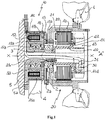
Figure 1 : shows an axial vertical section through a first example of embodiment of the apparatus according to the present invention; and -
Figure 2 : shows an axial vertical section through a second example of embodiment of the apparatus according to the present invention. - As shown in
Fig. 1 and assuming solely for the sake of easier description without a limiting meaning a longitudinal axis X-X corresponding to the axis of rotation of afan 1, as well as a front part A situated close, during use, to the radiator of the vehicle (indicated by a dot-dash line) and a rear part opposite to the front part in the longitudinal direction X-X, the apparatus for controlling the rotation of the fan according to the invention is designed such that: - the
fan 1 is integral with a bell member 1a mounted on the outer race 2a of a bearing 2, theinner race 2b of which is keyed onto afixed sleeve 3 extending parallel to the longitudinal axis X-X and preferably coaxial therewith as in the example shown; - the
sleeve 3 is internally hollow so as to allow the electrical connections to pass through and its rear end is joined together - preferably as one piece - with a first support flange 3a which can be fastened to the
base 5 of the engine by means of fixing means, for example of the screw type 5a; - On the axially opposite side to that which is connected to the
fan 1, the supporting bell member 1a is connected together with thearmature 13 of anelectromagnetic friction coupling 10 which comprises: - -) a
fixed electromagnet 12 which is housed inside an associatedseat 12a of the flange 3a of thesleeve 3 and preferably electrically connected, by means of cables 11d, to a thermostat (not shown) for measuring the temperature of the cooling fluid in the radiator; - -) a
rotor 11 arranged axially facing theelectromagnet 12, between the latter and thearmature 13, and mounted on a bearing 11a keyed onto thesleeve 3; in greater detail therotor 11 has anannular part 11b forming a disc for circulation of the magnetic flux induced by the electromagnet and a radially outer axial extension 11c configured as means for receiving the movement arranged in a position radially on the outside of the electromagnet, such as a pulley 11e, formed by radially outer teeth, suitable for engagement with amulti-groove belt 4 connected to the driving shaft, directly or via transmissions, and therefore able to cause rotation of therotor 11; - -) the
armature 13 is arranged axially on the opposite side of therotor 11 with respect to theelectromagnet 12 and is connected by means of a resilient membrane 13a to the bell member 1a of thefan 1; with this connection thearmature 13 is able to perform movements in the axial direction towards/away from therotor 11, while remaining locked in relative rotation with the bell member 1a. - As shown, the bell member 1a is also joined together with the
rotor 22 of anelectric motor 20, thestator 21 of which is mounted on asecond support flange 40 fastened to the front end of thesupport sleeve 3; thesecond flange 40 has a shapedradial extension 41 to which thestator 21 is fixed by means of screw-type fixing means 42; theradial extension 41 defines acoaxial seat 43 for housing an electronic drive andcontrol unit 30 of theelectric motor 20, which is connected by means of cables 32 passing through theflange 40 to theelectric motor 20 and supplied with power via theelectrical connections 31. - In this way the
fan 1 can be connected by means of the bell member 1a both to theelectromagnetic friction coupling 10 and to theelectric motor 20 which is current-controlled by means of the associatedcontrol unit 30. - With reference to
Figure 2 , according to a second embodiment of the apparatus of the invention, the electronic drive andcontrol unit 130 of theelectric motor 20 is arranged in an axially inner position coaxial with thestator 21 of the electric motor and preferably concentric therewith. As shown, preferably the second flange 140 supports theelectronic drive unit 130 and thestator 21 in a radially inner position and radially outer position, respectively. - In this configuration also, the second flange 140 may comprise a
radial extension 141 to which thestator 21 is fixed by means of through-screws 142 engaging with a corresponding female thread of theradial extension 141. - As shown in the examples, it is envisaged preferably that the electric motor is arranged in a position axially on the outside of the means for receiving the movement 11c;11e and/or of the electromagnetic friction coupling, which allows the radial dimensions of the apparatus to be further reduced.
- In the case of both the configurations, operation of the fan is dependent on the activation of one or the other of the two movement transmission/generating devices:
- in conditions where the
electromagnet 12 is not excited and themotor 20 de-energized, the bell member 1a is disconnected from all the movement sources and thefan 1 is at a standstill in the idle condition; - in conditions where the
electromagnet 12 is excited and themotor 20 de-energized, thearmature 13 is recalled against therotor 11 and thefan 1 is rotated with a number of revolutions equal or proportional to the number of revolutions of the driving shaft to which it is connected via thebelt 4; in this condition the friction coupling causes rotation of the electric rotor, which induces a current on the stator, generating recoverable energy; - in conditions where the
electromagnet 12 is not excited and themotor 20 energized, thearmature 13 and therefore thefan 1 are rotated by the rotor of themotor 20 with a number of revolutions determined by thecontrol unit 30 according to the actual cooling requirement. - In both embodiments the fan rotates in the direction - anticlockwise in the example of the Figure - such as to draw air from the outside towards the surface of the radiator arranged in front of the fan with respect to the direction of travel of the vehicle; according to the invention it is envisaged however that the
electric motor 20 may be powered with opposite currents so as to cause a rotation of therotor 22 of the electric motor and therefore thefan 1 in the direction - clockwise in the example - of a thrusting force of the air acting in the direction of travel of the vehicle so that, crossing the radiator from the inside towards the outside, the dirt which has accumulated on the surface of the radiator during the cooling cycles is removed, thus restoring the full functionality of the radiator which has been reduced in the meantime owing to the dirt. - It is therefore clear how the apparatus according to the invention is able to cause operation of the fan both so as to cool the cooling fluid contained in the radiator and, if convenient or required, so as to perform cleaning of the surface of the said radiator, which cleaning may take place also during normal travel of the vehicle and therefore without the vehicle stoppage downtime resulting from the need to cool the radiator in order to be able to access it manually for cleaning thereof.
- The second support flange joined together with the
sleeve 3 allows the electronic drive and control unit of the electric motor to be housed radially on the inside of the bell member 1a of the apparatus for controlling rotation of the fan, thus limiting the disturbances and eddy currents which are generated when the motor is controlled by a control unit arranged at a distance therefrom and connected by means of electric cables which pass through the area of the apparatus occupied by the electromagnetic friction coupling, while at the same time limiting the dimensions, in particular the radial dimensions. The configuration with a double support flange, where the second flange is fastened at the front to the sleeve by means of axial fixing means, facilitates mounting of the apparatus since the assembly composed of the stator and the electronic drive unit of the electric motor may be preassembled and then fixed in front of thesleeve 3 by means of thesecond flange 40, thus enabling easier mounting of the apparatus. It is also envisaged that the electric motor may be overpowered for short periods of time in order to increase both the torque and the speed thereof so as to improve the efficiency of removal of the dirt from the surface of the radiator and/or manage extreme cooling situations without having to resort to engagement of the friction coupling. - According to tests carried out it is estimated that the current supplied by the battery of the combustion engine may be 12V or 24V dc, i.e. sufficient to allow rotation of the fan up to about 50% of the maximum speed which can be produced with connection to the combustion engine which, above these values, is brought into play by means of the friction coupling.
- Although described in connection with a number of embodiments and a number of preferred examples of implementation of the invention, it is understood that the scope of protection of the present patent is defined solely by the claims below.
Claims (13)
- Apparatus for controlling the rotation about a longitudinal axis (X-X) of a fan (1) for cooling the cooling fluid contained in the radiator of a vehicle, comprising:- a fixed support sleeve (3), internally hollow and extending parallel to the longitudinal axis (X-X) of rotation of the fan;- a bell member (1a) for supporting the fan;- an electromagnetic friction coupling (10), arranged between the bell member (1a) and movement receiving means (11c;11e) for connection to the driving shaft of the vehicle;- an electric motor (20) for generating a rotational movement independent of the driving shaft of the vehicle, comprising a stator (21) and a rotor (22);- a first rear flange (3a) integral with the sleeve (3) and designed to support an electromagnet (12) of the electromagnetic friction coupling;characterized in that
the bell member (1a) is mounted on the outer race (2a) of a bearing (2), the inner race (2b) of which is keyed onto the support sleeve (3);
and in that it comprises a second front flange (40;140) integral with the sleeve (3), arranged in a position radially on the inside of the bell member (1a) supporting the fan and designed to support the stator (21) of the electric motor (20) and an electronic drive and control unit (30;130) for controlling and electronically driving the electric motor (20),
and in that the movement receiving means (11c;11e) are arranged in a position radially on the outside of the electromagnetic friction coupling. - Apparatus according to Claim 1, wherein the second flange (40) comprises a seat for housing the electronic drive and control unit (30).
- Apparatus according to Claim 1 or 2, wherein the electronic drive and control unit (30) for electronically driving the electric motor (20) is arranged in a position axially on the outside of the stator (21).
- Apparatus according to Claim 1 or 2, wherein the electronic drive and control unit (130) for electronically driving the electric motor (20) is arranged in a position axially on the inside of the stator (21).
- Apparatus according to the preceding claim, wherein the electronic drive and control unit (130) is coaxial with the stator (21) and preferably concentric therewith.
- Apparatus according to any one of the preceding claims, characterized in that the second flange (40;140) has a shaped radial extension (41;141) to which the stator (21) is fixed by means of screw-type fixing means (42).
- Apparatus according to any one of the preceding claims, characterized in that the second support flange (40;140) is axially joined to a front end of the sleeve (3) by means of fixing means.
- Apparatus according to any one of the preceding claims, characterized in that the rotor (22) of said electric motor (20) is fastened to the bell member for supporting the fan.
- Apparatus according to any one of the preceding claims, characterized in that the electric motor (20) can be overpowered for short time intervals.
- Apparatus according to any one of the preceding claims, characterized in that the electric motor is configured so as to be able to be alternately rotated so as to cause rotation of the fan (1), suitable for drawing air from the environment and forcing it through the radiator (6) in the opposite direction to that of movement, or rotation of the fan (1) in the opposite direction, suitable for forcing air through the radiator (6) towards the external environment in the same direction as that of movement.
- Apparatus according to any one of the preceding claims, characterized in that said electromagnetic friction coupling (10) comprises:-) a mechanical rotor (11) arranged facing the electromagnet (12) and mounted on a bearing (11a) keyed onto the sleeve (3);-) an armature (13) arranged in the axial direction on the opposite side of the rotor (11) with respect to the electromagnet (12), and connected by means of a resilient membrane (13a) to the bell member (1a) supporting the fan (1).
- Apparatus according to the preceding claim, characterized in that said mechanical rotor (11) has an annular part (11b) forming a disc for circulation of the magnetic flux induced by the electromagnet and an axial end extension (11c) configured as movement receiving means, in particular as a pulley (11e), preferably comprising a radially external toothing suitable for engagement with a multi-groove belt (4) for connection to the driving shaft of the vehicle.
- Apparatus according to any one of the preceding claims, characterized in that, in conditions where the electromagnet is excited, the friction coupling causes rotation of the rotor (22) of the electric motor (20), this inducing a current on the stator and generating recoverable energy.
Applications Claiming Priority (3)
| Application Number | Priority Date | Filing Date | Title |
|---|---|---|---|
| IT201700066329 | 2017-06-15 | ||
| IT201700066356 | 2017-06-15 | ||
| PCT/IB2018/054364 WO2018229705A1 (en) | 2017-06-15 | 2018-06-14 | Hybrid apparatus for controlling the rotation of a fan for cooling the cooling fluid of a vehicle |
Publications (2)
| Publication Number | Publication Date |
|---|---|
| EP3638916A1 EP3638916A1 (en) | 2020-04-22 |
| EP3638916B1 true EP3638916B1 (en) | 2021-04-28 |
Family
ID=62846220
Family Applications (1)
| Application Number | Title | Priority Date | Filing Date |
|---|---|---|---|
| EP18738378.1A Active EP3638916B1 (en) | 2017-06-15 | 2018-06-14 | Hybrid apparatus for controlling the rotation of a fan for cooling the cooling fluid of a vehicle |
Country Status (4)
| Country | Link |
|---|---|
| US (1) | US11506109B2 (en) |
| EP (1) | EP3638916B1 (en) |
| CN (1) | CN110741174B (en) |
| WO (1) | WO2018229705A1 (en) |
Families Citing this family (2)
| Publication number | Priority date | Publication date | Assignee | Title |
|---|---|---|---|---|
| WO2020261077A1 (en) * | 2019-06-24 | 2020-12-30 | Baruffaldi S.P.A. | Coolant pump for a vehicle |
| WO2026028096A1 (en) | 2024-08-02 | 2026-02-05 | Baruffaldi S.P.A. | Hybrid group for rotationally driving cooling fans of vehicles combusion engines |
Family Cites Families (14)
| Publication number | Priority date | Publication date | Assignee | Title |
|---|---|---|---|---|
| IT1292384B1 (en) * | 1997-06-19 | 1999-02-08 | Baruffaldi Spa | MOTORCYCLE TRANSMISSION DEVICE WITH ELECTROMAGNETIC CLUTCH AND EPICYCLOIDAL ROTISM FOR VEHICLE FANS |
| IT1316681B1 (en) * | 2000-02-29 | 2003-04-24 | Baruffaldi Spa | MOTORCYCLE TRANSMISSION DEVICE FOR MOTOR VEHICLE FANS |
| DE10035765A1 (en) * | 2000-07-22 | 2002-02-07 | Bayerische Motoren Werke Ag | Drive for coolant air blower of internal combustion engine, has rotor of motor arranged at external perimeter of coolant air blower |
| ITMI20012616A1 (en) * | 2001-12-12 | 2003-06-12 | Baruffaldi Spa | AIR COOLING EQUIPMENT FOR VEHICLE COOLING FLUIDS AND SIMILAR WITH FAN WITH ADJUSTABLE BLADES AND VEHICLES |
| ITMI20041813A1 (en) * | 2004-09-22 | 2004-12-22 | Foussianes Nicholas B | MOTOR COOLING FAN MOTOR TRANSMISSION DEVICE. |
| EP1683948A3 (en) * | 2004-12-28 | 2008-07-02 | Baruffaldi S.p.A. | Device for transmitting the movement to fans, in particular of vehicles |
| ITMI20051423A1 (en) * | 2005-07-22 | 2007-01-23 | Baruffaldi Spa | STILL DOUBLE DEVICE FOR THE TRANSMISSION OF THE MOTORCYCLE TO VEHICLE ENGINE COOLING FANS |
| CN102216585B (en) * | 2008-11-23 | 2014-10-15 | 博格华纳公司 | Fan drive system with sensor feedback |
| DE102009033616A1 (en) * | 2009-07-17 | 2011-01-20 | Karl Heinz Linnig Gmbh & Co. Kg | Cooling device, in particular engine cooling device, with a secondary drive machine |
| FR2990000A1 (en) * | 2012-04-26 | 2013-11-01 | Peugeot Citroen Automobiles Sa | Method for cooling propulsion engine of car, involves supplying electric motor with power for rotating fan blades in reverse direction in response to stoppage of propulsion engine if temperature of outside air is less than specific degrees |
| DE102014220692A1 (en) * | 2014-10-13 | 2016-04-14 | Deere & Company | Method for the combined preheating and cooling of a coolant |
| CN205277580U (en) * | 2015-09-30 | 2016-06-01 | 龙口中宇机械有限公司 | Safe formula three -speed electromagnetic fan clutch |
| WO2017080593A1 (en) * | 2015-11-11 | 2017-05-18 | Baruffaldi S.P.A. | Apparatus for actuating and controlling the rotation of blades of fans for cooling the coolant in machines/vehicles. |
| EP3638895B1 (en) * | 2017-06-15 | 2021-07-28 | Baruffaldi S.p.A. | Mixed hybrid-operation group for recirculating and cooling the cooling fluid of a vehicle |
-
2018
- 2018-06-14 CN CN201880039348.8A patent/CN110741174B/en active Active
- 2018-06-14 WO PCT/IB2018/054364 patent/WO2018229705A1/en not_active Ceased
- 2018-06-14 US US16/619,023 patent/US11506109B2/en active Active
- 2018-06-14 EP EP18738378.1A patent/EP3638916B1/en active Active
Non-Patent Citations (1)
| Title |
|---|
| None * |
Also Published As
| Publication number | Publication date |
|---|---|
| CN110741174B (en) | 2021-03-05 |
| WO2018229705A1 (en) | 2018-12-20 |
| US11506109B2 (en) | 2022-11-22 |
| CN110741174A (en) | 2020-01-31 |
| US20210079832A1 (en) | 2021-03-18 |
| EP3638916A1 (en) | 2020-04-22 |
Similar Documents
| Publication | Publication Date | Title |
|---|---|---|
| US9279460B2 (en) | Accessory drive with friction clutch and electric motor | |
| US11085449B2 (en) | Pump assembly for recirculating a cooling fluid of a heat engine | |
| US9112387B2 (en) | Air-cooled electrical machine with automatic clutch | |
| CN104919204A (en) | Fail Safe Dry Friction Clutch for Coolant Pumps | |
| US7472778B2 (en) | Device for transmitting the movement to fans, in particular of vehicles | |
| CN104870822A (en) | Device for driving an ancillary unit of an internal combustion engine | |
| US20010017250A1 (en) | Movement transmission device for motor vehicle fans | |
| EP3638916B1 (en) | Hybrid apparatus for controlling the rotation of a fan for cooling the cooling fluid of a vehicle | |
| EP1696111B1 (en) | Device for transmitting the rotating movement to a driven shaft, in particular for fluid recirculating pumps | |
| US7757830B2 (en) | Dual armature device for transmitting the movement to fans for cooling the engine of motor vehicles | |
| EP3638895B1 (en) | Mixed hybrid-operation group for recirculating and cooling the cooling fluid of a vehicle | |
| US20110253077A1 (en) | Reversible Double-Acting Electromagnetic Device For Transmitting The Movement To/From A Driven/Driving Member | |
| US20060131120A1 (en) | Device for transmitting the movement to fans for cooling engines | |
| US20060086585A1 (en) | Device for transmitting the rotating movement to a driven shaft, in particular for fluid recirculating pumps | |
| EP3583320B1 (en) | Pump for circulating a cooling fluid for combustion engines with electric motor control device | |
| WO2019082025A1 (en) | Integrated apparatus for simultaneous control and operation of a fan and the impeller of a vehicle pump | |
| EP3638896B1 (en) | Pump for recirculating a cooling liquid for combustion engines with hybrid control system comprising electromagnetic friction coupling and electric motor which are axially offset | |
| WO2018007934A1 (en) | Apparatus for performing reverse rotation of fans for cooling radiators of operating machines and/or vehicles | |
| EP2110530A1 (en) | Fluid recirculating pump with device for transmission of the rotational movement to the associated driven shaft | |
| EP2599976A1 (en) | Device for transmitting the movement to fans for cooling engines with stoppage of the fan in an idle condition thereof | |
| EP3714140B1 (en) | Device for driving at three speeds fans for cooling the coolant in motor vehicles | |
| JP2007126065A (en) | Bearing device for motor rotary shaft in hybrid prime mover | |
| US20250188936A1 (en) | Operating assembly for pumps for recirculating a cooling fluid of combustion engines and recirculating pump provided with such an operating assembly | |
| EP3987162B1 (en) | Coolant pump for a vehicle | |
| CN119231843A (en) | Hybrid module |
Legal Events
| Date | Code | Title | Description |
|---|---|---|---|
| STAA | Information on the status of an ep patent application or granted ep patent |
Free format text: STATUS: UNKNOWN |
|
| STAA | Information on the status of an ep patent application or granted ep patent |
Free format text: STATUS: THE INTERNATIONAL PUBLICATION HAS BEEN MADE |
|
| PUAI | Public reference made under article 153(3) epc to a published international application that has entered the european phase |
Free format text: ORIGINAL CODE: 0009012 |
|
| STAA | Information on the status of an ep patent application or granted ep patent |
Free format text: STATUS: REQUEST FOR EXAMINATION WAS MADE |
|
| 17P | Request for examination filed |
Effective date: 20200109 |
|
| AK | Designated contracting states |
Kind code of ref document: A1 Designated state(s): AL AT BE BG CH CY CZ DE DK EE ES FI FR GB GR HR HU IE IS IT LI LT LU LV MC MK MT NL NO PL PT RO RS SE SI SK SM TR |
|
| AX | Request for extension of the european patent |
Extension state: BA ME |
|
| DAV | Request for validation of the european patent (deleted) | ||
| DAX | Request for extension of the european patent (deleted) | ||
| GRAP | Despatch of communication of intention to grant a patent |
Free format text: ORIGINAL CODE: EPIDOSNIGR1 |
|
| STAA | Information on the status of an ep patent application or granted ep patent |
Free format text: STATUS: GRANT OF PATENT IS INTENDED |
|
| RIC1 | Information provided on ipc code assigned before grant |
Ipc: F01P 5/04 20060101ALI20201029BHEP Ipc: F04D 29/059 20060101ALI20201029BHEP Ipc: F01P 7/04 20060101ALI20201029BHEP Ipc: F04D 25/06 20060101ALI20201029BHEP Ipc: F16D 27/112 20060101AFI20201029BHEP Ipc: F01P 7/08 20060101ALI20201029BHEP Ipc: F04D 25/02 20060101ALI20201029BHEP |
|
| INTG | Intention to grant announced |
Effective date: 20201126 |
|
| GRAS | Grant fee paid |
Free format text: ORIGINAL CODE: EPIDOSNIGR3 |
|
| GRAA | (expected) grant |
Free format text: ORIGINAL CODE: 0009210 |
|
| STAA | Information on the status of an ep patent application or granted ep patent |
Free format text: STATUS: THE PATENT HAS BEEN GRANTED |
|
| AK | Designated contracting states |
Kind code of ref document: B1 Designated state(s): AL AT BE BG CH CY CZ DE DK EE ES FI FR GB GR HR HU IE IS IT LI LT LU LV MC MK MT NL NO PL PT RO RS SE SI SK SM TR |
|
| REG | Reference to a national code |
Ref country code: GB Ref legal event code: FG4D |
|
| REG | Reference to a national code |
Ref country code: CH Ref legal event code: EP |
|
| REG | Reference to a national code |
Ref country code: AT Ref legal event code: REF Ref document number: 1387403 Country of ref document: AT Kind code of ref document: T Effective date: 20210515 |
|
| REG | Reference to a national code |
Ref country code: DE Ref legal event code: R096 Ref document number: 602018016290 Country of ref document: DE |
|
| REG | Reference to a national code |
Ref country code: IE Ref legal event code: FG4D |
|
| REG | Reference to a national code |
Ref country code: LT Ref legal event code: MG9D |
|
| REG | Reference to a national code |
Ref country code: AT Ref legal event code: MK05 Ref document number: 1387403 Country of ref document: AT Kind code of ref document: T Effective date: 20210428 |
|
| PG25 | Lapsed in a contracting state [announced via postgrant information from national office to epo] |
Ref country code: LT Free format text: LAPSE BECAUSE OF FAILURE TO SUBMIT A TRANSLATION OF THE DESCRIPTION OR TO PAY THE FEE WITHIN THE PRESCRIBED TIME-LIMIT Effective date: 20210428 Ref country code: HR Free format text: LAPSE BECAUSE OF FAILURE TO SUBMIT A TRANSLATION OF THE DESCRIPTION OR TO PAY THE FEE WITHIN THE PRESCRIBED TIME-LIMIT Effective date: 20210428 Ref country code: FI Free format text: LAPSE BECAUSE OF FAILURE TO SUBMIT A TRANSLATION OF THE DESCRIPTION OR TO PAY THE FEE WITHIN THE PRESCRIBED TIME-LIMIT Effective date: 20210428 Ref country code: NL Free format text: LAPSE BECAUSE OF FAILURE TO SUBMIT A TRANSLATION OF THE DESCRIPTION OR TO PAY THE FEE WITHIN THE PRESCRIBED TIME-LIMIT Effective date: 20210428 Ref country code: AT Free format text: LAPSE BECAUSE OF FAILURE TO SUBMIT A TRANSLATION OF THE DESCRIPTION OR TO PAY THE FEE WITHIN THE PRESCRIBED TIME-LIMIT Effective date: 20210428 Ref country code: BG Free format text: LAPSE BECAUSE OF FAILURE TO SUBMIT A TRANSLATION OF THE DESCRIPTION OR TO PAY THE FEE WITHIN THE PRESCRIBED TIME-LIMIT Effective date: 20210728 |
|
| PG25 | Lapsed in a contracting state [announced via postgrant information from national office to epo] |
Ref country code: LV Free format text: LAPSE BECAUSE OF FAILURE TO SUBMIT A TRANSLATION OF THE DESCRIPTION OR TO PAY THE FEE WITHIN THE PRESCRIBED TIME-LIMIT Effective date: 20210428 Ref country code: NO Free format text: LAPSE BECAUSE OF FAILURE TO SUBMIT A TRANSLATION OF THE DESCRIPTION OR TO PAY THE FEE WITHIN THE PRESCRIBED TIME-LIMIT Effective date: 20210728 Ref country code: PL Free format text: LAPSE BECAUSE OF FAILURE TO SUBMIT A TRANSLATION OF THE DESCRIPTION OR TO PAY THE FEE WITHIN THE PRESCRIBED TIME-LIMIT Effective date: 20210428 Ref country code: RS Free format text: LAPSE BECAUSE OF FAILURE TO SUBMIT A TRANSLATION OF THE DESCRIPTION OR TO PAY THE FEE WITHIN THE PRESCRIBED TIME-LIMIT Effective date: 20210428 Ref country code: PT Free format text: LAPSE BECAUSE OF FAILURE TO SUBMIT A TRANSLATION OF THE DESCRIPTION OR TO PAY THE FEE WITHIN THE PRESCRIBED TIME-LIMIT Effective date: 20210830 Ref country code: SE Free format text: LAPSE BECAUSE OF FAILURE TO SUBMIT A TRANSLATION OF THE DESCRIPTION OR TO PAY THE FEE WITHIN THE PRESCRIBED TIME-LIMIT Effective date: 20210428 Ref country code: GR Free format text: LAPSE BECAUSE OF FAILURE TO SUBMIT A TRANSLATION OF THE DESCRIPTION OR TO PAY THE FEE WITHIN THE PRESCRIBED TIME-LIMIT Effective date: 20210729 Ref country code: IS Free format text: LAPSE BECAUSE OF FAILURE TO SUBMIT A TRANSLATION OF THE DESCRIPTION OR TO PAY THE FEE WITHIN THE PRESCRIBED TIME-LIMIT Effective date: 20210828 |
|
| REG | Reference to a national code |
Ref country code: NL Ref legal event code: MP Effective date: 20210428 |
|
| PG25 | Lapsed in a contracting state [announced via postgrant information from national office to epo] |
Ref country code: DK Free format text: LAPSE BECAUSE OF FAILURE TO SUBMIT A TRANSLATION OF THE DESCRIPTION OR TO PAY THE FEE WITHIN THE PRESCRIBED TIME-LIMIT Effective date: 20210428 Ref country code: CZ Free format text: LAPSE BECAUSE OF FAILURE TO SUBMIT A TRANSLATION OF THE DESCRIPTION OR TO PAY THE FEE WITHIN THE PRESCRIBED TIME-LIMIT Effective date: 20210428 Ref country code: MC Free format text: LAPSE BECAUSE OF FAILURE TO SUBMIT A TRANSLATION OF THE DESCRIPTION OR TO PAY THE FEE WITHIN THE PRESCRIBED TIME-LIMIT Effective date: 20210428 Ref country code: SM Free format text: LAPSE BECAUSE OF FAILURE TO SUBMIT A TRANSLATION OF THE DESCRIPTION OR TO PAY THE FEE WITHIN THE PRESCRIBED TIME-LIMIT Effective date: 20210428 Ref country code: RO Free format text: LAPSE BECAUSE OF FAILURE TO SUBMIT A TRANSLATION OF THE DESCRIPTION OR TO PAY THE FEE WITHIN THE PRESCRIBED TIME-LIMIT Effective date: 20210428 Ref country code: SK Free format text: LAPSE BECAUSE OF FAILURE TO SUBMIT A TRANSLATION OF THE DESCRIPTION OR TO PAY THE FEE WITHIN THE PRESCRIBED TIME-LIMIT Effective date: 20210428 Ref country code: ES Free format text: LAPSE BECAUSE OF FAILURE TO SUBMIT A TRANSLATION OF THE DESCRIPTION OR TO PAY THE FEE WITHIN THE PRESCRIBED TIME-LIMIT Effective date: 20210428 Ref country code: EE Free format text: LAPSE BECAUSE OF FAILURE TO SUBMIT A TRANSLATION OF THE DESCRIPTION OR TO PAY THE FEE WITHIN THE PRESCRIBED TIME-LIMIT Effective date: 20210428 |
|
| REG | Reference to a national code |
Ref country code: DE Ref legal event code: R097 Ref document number: 602018016290 Country of ref document: DE Ref country code: CH Ref legal event code: PL |
|
| PLBE | No opposition filed within time limit |
Free format text: ORIGINAL CODE: 0009261 |
|
| STAA | Information on the status of an ep patent application or granted ep patent |
Free format text: STATUS: NO OPPOSITION FILED WITHIN TIME LIMIT |
|
| REG | Reference to a national code |
Ref country code: BE Ref legal event code: MM Effective date: 20210630 |
|
| PG25 | Lapsed in a contracting state [announced via postgrant information from national office to epo] |
Ref country code: LU Free format text: LAPSE BECAUSE OF NON-PAYMENT OF DUE FEES Effective date: 20210614 |
|
| 26N | No opposition filed |
Effective date: 20220131 |
|
| PG25 | Lapsed in a contracting state [announced via postgrant information from national office to epo] |
Ref country code: LI Free format text: LAPSE BECAUSE OF NON-PAYMENT OF DUE FEES Effective date: 20210630 Ref country code: IE Free format text: LAPSE BECAUSE OF NON-PAYMENT OF DUE FEES Effective date: 20210614 Ref country code: CH Free format text: LAPSE BECAUSE OF NON-PAYMENT OF DUE FEES Effective date: 20210630 |
|
| PG25 | Lapsed in a contracting state [announced via postgrant information from national office to epo] |
Ref country code: IS Free format text: LAPSE BECAUSE OF FAILURE TO SUBMIT A TRANSLATION OF THE DESCRIPTION OR TO PAY THE FEE WITHIN THE PRESCRIBED TIME-LIMIT Effective date: 20210828 Ref country code: AL Free format text: LAPSE BECAUSE OF FAILURE TO SUBMIT A TRANSLATION OF THE DESCRIPTION OR TO PAY THE FEE WITHIN THE PRESCRIBED TIME-LIMIT Effective date: 20210428 |
|
| PG25 | Lapsed in a contracting state [announced via postgrant information from national office to epo] |
Ref country code: BE Free format text: LAPSE BECAUSE OF NON-PAYMENT OF DUE FEES Effective date: 20210630 |
|
| GBPC | Gb: european patent ceased through non-payment of renewal fee |
Effective date: 20220614 |
|
| PG25 | Lapsed in a contracting state [announced via postgrant information from national office to epo] |
Ref country code: GB Free format text: LAPSE BECAUSE OF NON-PAYMENT OF DUE FEES Effective date: 20220614 |
|
| P01 | Opt-out of the competence of the unified patent court (upc) registered |
Effective date: 20230417 |
|
| PG25 | Lapsed in a contracting state [announced via postgrant information from national office to epo] |
Ref country code: CY Free format text: LAPSE BECAUSE OF FAILURE TO SUBMIT A TRANSLATION OF THE DESCRIPTION OR TO PAY THE FEE WITHIN THE PRESCRIBED TIME-LIMIT Effective date: 20210428 |
|
| PG25 | Lapsed in a contracting state [announced via postgrant information from national office to epo] |
Ref country code: HU Free format text: LAPSE BECAUSE OF FAILURE TO SUBMIT A TRANSLATION OF THE DESCRIPTION OR TO PAY THE FEE WITHIN THE PRESCRIBED TIME-LIMIT; INVALID AB INITIO Effective date: 20180614 |
|
| PG25 | Lapsed in a contracting state [announced via postgrant information from national office to epo] |
Ref country code: MK Free format text: LAPSE BECAUSE OF FAILURE TO SUBMIT A TRANSLATION OF THE DESCRIPTION OR TO PAY THE FEE WITHIN THE PRESCRIBED TIME-LIMIT Effective date: 20210428 |
|
| PG25 | Lapsed in a contracting state [announced via postgrant information from national office to epo] |
Ref country code: MT Free format text: LAPSE BECAUSE OF FAILURE TO SUBMIT A TRANSLATION OF THE DESCRIPTION OR TO PAY THE FEE WITHIN THE PRESCRIBED TIME-LIMIT Effective date: 20210428 |
|
| PGFP | Annual fee paid to national office [announced via postgrant information from national office to epo] |
Ref country code: FR Payment date: 20250627 Year of fee payment: 8 |
|
| PGFP | Annual fee paid to national office [announced via postgrant information from national office to epo] |
Ref country code: DE Payment date: 20250701 Year of fee payment: 8 |
|
| PGFP | Annual fee paid to national office [announced via postgrant information from national office to epo] |
Ref country code: IT Payment date: 20250627 Year of fee payment: 8 |
|
| PG25 | Lapsed in a contracting state [announced via postgrant information from national office to epo] |
Ref country code: TR Free format text: LAPSE BECAUSE OF FAILURE TO SUBMIT A TRANSLATION OF THE DESCRIPTION OR TO PAY THE FEE WITHIN THE PRESCRIBED TIME-LIMIT Effective date: 20210428 |