EP3638897B1 - Turbopompe comprenant un inducteur amélioré - Google Patents
Turbopompe comprenant un inducteur amélioré Download PDFInfo
- Publication number
- EP3638897B1 EP3638897B1 EP18773501.4A EP18773501A EP3638897B1 EP 3638897 B1 EP3638897 B1 EP 3638897B1 EP 18773501 A EP18773501 A EP 18773501A EP 3638897 B1 EP3638897 B1 EP 3638897B1
- Authority
- EP
- European Patent Office
- Prior art keywords
- cavity
- inductor
- intake
- flow
- induction duct
- Prior art date
- Legal status (The legal status is an assumption and is not a legal conclusion. Google has not performed a legal analysis and makes no representation as to the accuracy of the status listed.)
- Active
Links
Images

Classifications
-
- F—MECHANICAL ENGINEERING; LIGHTING; HEATING; WEAPONS; BLASTING
- F02—COMBUSTION ENGINES; HOT-GAS OR COMBUSTION-PRODUCT ENGINE PLANTS
- F02K—JET-PROPULSION PLANTS
- F02K9/00—Rocket-engine plants, i.e. plants carrying both fuel and oxidant therefor; Control thereof
- F02K9/42—Rocket-engine plants, i.e. plants carrying both fuel and oxidant therefor; Control thereof using liquid or gaseous propellants
- F02K9/44—Feeding propellants
- F02K9/46—Feeding propellants using pumps
-
- F—MECHANICAL ENGINEERING; LIGHTING; HEATING; WEAPONS; BLASTING
- F04—POSITIVE - DISPLACEMENT MACHINES FOR LIQUIDS; PUMPS FOR LIQUIDS OR ELASTIC FLUIDS
- F04D—NON-POSITIVE-DISPLACEMENT PUMPS
- F04D1/00—Radial-flow pumps, e.g. centrifugal pumps; Helico-centrifugal pumps
- F04D1/02—Radial-flow pumps, e.g. centrifugal pumps; Helico-centrifugal pumps having non-centrifugal stages, e.g. centripetal
- F04D1/025—Comprising axial and radial stages
-
- F—MECHANICAL ENGINEERING; LIGHTING; HEATING; WEAPONS; BLASTING
- F04—POSITIVE - DISPLACEMENT MACHINES FOR LIQUIDS; PUMPS FOR LIQUIDS OR ELASTIC FLUIDS
- F04D—NON-POSITIVE-DISPLACEMENT PUMPS
- F04D29/00—Details, component parts, or accessories
- F04D29/18—Rotors
- F04D29/181—Axial flow rotors
- F04D29/183—Semi axial flow rotors
-
- F—MECHANICAL ENGINEERING; LIGHTING; HEATING; WEAPONS; BLASTING
- F04—POSITIVE - DISPLACEMENT MACHINES FOR LIQUIDS; PUMPS FOR LIQUIDS OR ELASTIC FLUIDS
- F04D—NON-POSITIVE-DISPLACEMENT PUMPS
- F04D29/00—Details, component parts, or accessories
- F04D29/18—Rotors
- F04D29/22—Rotors specially for centrifugal pumps
- F04D29/2261—Rotors specially for centrifugal pumps with special measures
- F04D29/2277—Rotors specially for centrifugal pumps with special measures for increasing NPSH or dealing with liquids near boiling-point
-
- F—MECHANICAL ENGINEERING; LIGHTING; HEATING; WEAPONS; BLASTING
- F04—POSITIVE - DISPLACEMENT MACHINES FOR LIQUIDS; PUMPS FOR LIQUIDS OR ELASTIC FLUIDS
- F04D—NON-POSITIVE-DISPLACEMENT PUMPS
- F04D29/00—Details, component parts, or accessories
- F04D29/40—Casings; Connections of working fluid
- F04D29/42—Casings; Connections of working fluid for radial or helico-centrifugal pumps
- F04D29/426—Casings; Connections of working fluid for radial or helico-centrifugal pumps especially adapted for liquid pumps
- F04D29/4293—Details of fluid inlet or outlet
-
- F—MECHANICAL ENGINEERING; LIGHTING; HEATING; WEAPONS; BLASTING
- F04—POSITIVE - DISPLACEMENT MACHINES FOR LIQUIDS; PUMPS FOR LIQUIDS OR ELASTIC FLUIDS
- F04D—NON-POSITIVE-DISPLACEMENT PUMPS
- F04D29/00—Details, component parts, or accessories
- F04D29/66—Combating cavitation, whirls, noise, vibration or the like; Balancing
- F04D29/68—Combating cavitation, whirls, noise, vibration or the like; Balancing by influencing boundary layers
- F04D29/688—Combating cavitation, whirls, noise, vibration or the like; Balancing by influencing boundary layers especially adapted for liquid pumps
Definitions
- This disclosure relates to turbopumps for spacecraft engines, and more specifically relates to the part of a turbopump comprising an inductor.
- Turbopumps of spacecraft commonly comprise an inductor producing a pressure rise in the flow of fluid upstream of a spinning wheel.
- the inductor of a turbopump commonly generates a recirculation of fluid passing through the clearance, from a high pressure region to a low pressure region upstream of the inductor.
- This fluid recirculation is problematic insofar as it greatly reduces the effective section of the duct leading to the inductor, and therefore significantly increases the speed of the fluid in this duct which causes a phenomenon of cavitation at the inductor level.
- This recirculation is particularly problematic at low flow, for which it can then extend over several times the length of the inductor, and therefore impact the elements upstream of the inductor.
- This presentation thus aims to at least partially respond to these issues.
- This disclosure relates to a spacecraft turbopump comprising an intake duct opening into an intake cavity delimited by an internal wall, a spinning wheel, an induction duct extending from the intake cavity, an inductor mounted in the induction duct, upstream of the impeller, a sleeve extending into the intake cavity upstream of the inductor, in the extension of the induction duct, the sleeve and the internal wall of the intake cavity defining a secondary cavity extending around the sleeve and in fluid communication with the intake cavity, said sleeve having a plurality of recirculation ducts opening into the secondary cavity on the one hand, and into the induction duct upstream of a leading edge of the inductor d 'somewhere else.
- Each of said recirculation ducts has a first end opening into the induction duct, and a second end opening into the secondary cavity.
- Each of said recirculation ducts has an increasing section from the first end to the second end.
- Each of said recirculation conduits typically defines a fluid flow having an inlet tangential component at the first end, and an outlet tangential component that is strictly less than the inlet tangential component at the second end.
- each of the recirculation ducts has for example a first end opening into the induction duct at the level of the leading edge of the inductor.
- Each of the recirculation ducts typically has a first end opening into the induction duct upstream of the leading edge of the inductor.
- the secondary cavity is formed so that the flow reaching said secondary cavity via the recirculation ducts is routed to the intake cavity.
- the present disclosure also relates to a spacecraft provided with such a turbopump.
- a spacecraft turbopump according to one aspect of the invention is described below.
- turbopump essentially relates to the portion of the turbopump comprising an inductor, as well as the associated ducts.
- the general structure of a turbopump is well known, and the other elements will therefore not be described in detail here.
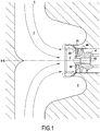
- the figure 1 shows schematically a portion of a turbopump comprising an intake duct 1 opening into an intake cavity 2 centered on an axis of rotation XX, and leading to an induction duct 3 in which an inductor 4 is mounted.
- the intake duct 1 is configured to be linked to a fluid intake line, this fluid then being routed to the intake cavity, then to the induction duct 3 and through the inductor 4 before d 'reach the downstream stages of the turbopump such as an impeller, these downstream stages not being shown in the figures.
- the inductor 4 is configured so as to perform a function of suctioning the fluid with a view to leading it to the downstream stages of the turbopump.
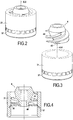
- the inductor 4 as shown is mounted on a rotating hub 42, and has three helical patterns 44 extending upstream. downstream of the inductor 4. It will be understood that such a geometry of the inductor 4 is given by way of example, but that the inductor 4 is not limited to such a geometry.
- An upstream front 46 of the inductor 4 is defined, corresponding to the upstream front of the helical patterns in the direction of the flow of the fluid.
- the induction duct 3 defines a sleeve 31 surrounding the inductor 4. More precisely, one end of the induction duct 3 opening into the intake cavity 2 protrudes into the intake cavity 3, so as to define a sleeve 31 of generally cylindrical shape of revolution within which the inductor 4 is placed.
- the sleeve 31 has been isolated and shown as a tubular portion for purposes of illustration.
- This end of the induction duct 3 protruding into the intake cavity 3 defines a secondary cavity 5, surrounding said end of the induction duct 3 protruding into the intake cavity 3.
- This secondary cavity 5 is in fluid communication. with the intake cavity 2, but is advantageously formed so as to be outside the main flow of fluid going from the intake pipe 1 to the induction pipe 3 (symbolized by arrows in solid lines on the figure 1 ) and thus form a cavity which one qualifies as "dead”, that is to say a cavity in which the flow is carried out at low speed with respect to the flow between the inlet pipe 1 and the induction pipe 3, so that the flow in this secondary cavity 5 does not disturb the flow within the inlet cavity 2.
- the sleeve 31 has a plurality of recirculation ducts 35 passing through, thus defining a passage between the induction duct 3 and the secondary cavity 5. This defines for each recirculation duct a first end 36 opening into the induction duct 3, and a second end 37 opening into the secondary cavity 5.
- the geometry of the recirculation ducts 35 is visible in particular on the figures 5, 6A and 6B , the figures 6A and 6B schematically showing the internal volume of the recirculation conduits 35 taken in isolation.
- the recirculation conduits 35 allow a flow of fluid from the induction conduit 3 to the secondary cavity 5, the flow being established naturally in this direction due to the relative pressure within the secondary cavity 5 which is lower than the pressure within the induction duct 3.
- Such a configuration of the recirculation ducts 35 thus makes it possible to slow down and straighten the flow of fluid taken from the induction duct 3 before it is injected into the secondary cavity 5.
- the first ends of the recirculation conduits 35 are positioned upstream of the upstream front 46 of the inductor 4 relative to the direction of the fluid flow. Such a positioning allows part of the flow of fluid to escape from the induction duct 3 towards the secondary cavity 5, and thus makes it possible to avoid or at least minimize the appearance of a reflux phenomenon of fluid through the inductor 4. In fact, the fluid which could form a reflux is here evacuated from the induction duct 3 via the recirculation ducts 35.
- the proposed structure makes it possible to avoid the formation of a reflux upstream of the inductor 4 which would reduce the effective section of the induction duct 3.
- the proposed structure indeed allows to evacuate part of the flow towards the secondary cavity 5 which is a "dead" cavity, so that this flow leaving the induction duct 3 does not disturb the flow of fluid entering the induction duct 3.
- the recirculation ducts 35 have an increasing section from the first end 36 to the second end 37. Such a progressive increase in the section of the recirculation ducts 35 makes it possible to reduce the speed d fluid flow between the first end 36 and the second end 37.
- the recirculation conduits 35 further typically have a non-linear shape.
- the recirculation conduits 35 are formed so that the admission of the fluid via the first end 36 is carried out in a direction having a tangential component and a radial component each not zero with respect to the cylindrical internal section of revolution of the sleeve 31.
- the discharge of fluid via the second end 37 is itself typically carried out in a radial or essentially radial direction, or at the very least in a direction having a less tangential component with respect to the tangential component at the fluid inlet via the first end 36.
- the recirculation ducts are further dimensioned so as to take a calibrated sample of the flow of fluid passing through the induction duct 3, so as to maintain a sufficient flow passing through the inductor 4 for the operation of the elements of the turbopump in downstream of the inductor 4.
- the proposed structure therefore makes it possible to perform a plurality of functions, in particular a function of sucking all or part of the flow which could cause a reflux upstream of the inductor 4, a function of rectifying the flow thus withdrawn before its injection. in the secondary cavity 5, a function of reducing the speed of the flow withdrawn before its injection into the secondary cavity 5, and a function of homogenization of the flow withdrawn with the main flow.
- turbopump comprising an inductor 4 supplied by radial intake ducts 1.
- present description can also be transposed for an inductor having axial intake ducts, the functionalities then being unchanged.
Landscapes
- Engineering & Computer Science (AREA)
- Mechanical Engineering (AREA)
- General Engineering & Computer Science (AREA)
- Chemical & Material Sciences (AREA)
- Combustion & Propulsion (AREA)
- Structures Of Non-Positive Displacement Pumps (AREA)
- Jet Pumps And Other Pumps (AREA)
Description
- Le présent exposé concerne les turbopompes pour moteurs d'engins spatiaux, et concerne plus précisément la partie d'une turbopompe comprenant un inducteur.
- Les turbopompes d'engins spatiaux comprennent communément un inducteur réalisant une montée en pression du flux de fluide en amont d'un rouet.
- Cependant, de par sa géométrie, l'inducteur d'une turbopompe génère communément une recirculation de fluide en passant par le jeu, d'une région haute pression vers une région basse pression en amont de l'inducteur. Cette recirculation de fluide est problématique dans la mesure où elle diminue fortement la section effective du conduit menant à l'inducteur, et augmente donc de manière importante la vitesse du fluide dans cette conduite ce qui entraine un phénomène de cavitation au niveau de l'inducteur. Cette recirculation est particulièrement problématique à bas débit, pour lesquels elle peut alors s'étendre sur plusieurs fois la longueur de l'inducteur, et donc venir impacter les éléments en amont de l'inducteur.
- Ce phénomène entraine donc des conséquences et risques importants pour un lanceur, notamment l'augmentation du risque d'apparition d'effet d'oscillations mécaniques non amorties, la nécessité de surdimensionner différents éléments et notamment les réservoirs d'ergol, et entraine un risque vis-à-vis de l'intégrité mécanique de la turbopompe. Les documents
US 3677659 etUS 4375938 présentent des pompes munies de conduits de recirculation selon l'état de la technique. - Le présent exposé vise ainsi à répondre au moins partiellement à ces problématiques.
- Le présent exposé concerne une turbopompe d'engin spatial comprenant
un conduit d'admission débouchant dans une cavité d'admission délimitée par une paroi interne,
un rouet,
un conduit d'induction s'étendant depuis la cavité d'admission,
un inducteur monté dans le conduit d'induction, en amont du rouet,
un manchon s'étendant dans la cavité d'admission en amont de l'inducteur, dans le prolongement du conduit d'induction, le manchon et la paroi interne de la cavité d'admission définissant une cavité secondaire s'étendant autour du manchon et en communication fluide avec la cavité d'admission, ledit manchon présentant une pluralité de conduits de recirculation débouchant dans la cavité secondaire d'une part, et dans le conduit d'induction en amont d'un bord d'attaque de l'inducteur d'autre part. - Chacun desdits conduits de recirculation présente une première extrémité débouchant dans le conduit d'induction, et une seconde extrémité débouchant dans la cavité secondaire.
- Chacun desdits conduits de recirculation présente une section croissante depuis la première extrémité vers la seconde extrémité.
- Chacun desdits conduits de recirculation définit typiquement une circulation de fluide présentant une composante tangentielle d'entrée au niveau de la première extrémité, et une composante tangentielle de sortie strictement inférieure à la composante tangentielle d'entrée au niveau de la seconde extrémité.
- Selon un exemple non revendiqué, chacun des conduits de recirculation présente par exemple une première extrémité débouchant dans le conduit d'induction au niveau du bord d'attaque de l'inducteur.
- Chacun des conduits de recirculation présente typiquement une première extrémité débouchant dans le conduit d'induction en amont du bord d'attaque de l'inducteur.
- Selon un exemple, la cavité secondaire est formée de manière à ce que flux parvenant dans ladite cavité secondaire via les conduits de recirculation soit acheminé vers la cavité d'admission.
- Le présent exposé concerne également un engin spatial muni d'une telle turbopompe.
- L'invention et ses avantages seront mieux compris à la lecture de la description détaillée faite ci-après de différents modes de réalisation de l'invention donnés à titre d'exemples non limitatifs. Cette description fait référence aux pages de figures annexées, sur lesquelles :
- la
figure 1 ; représente une vue en coupe d'une portion de turbopompe selon un aspect de l'invention, - les
figures 2, 3 et 4 sont des vues représentant l'inducteur d'une telle turbopompe ainsi qu'un manchon associé, - les
figures 5, et 6A et 6B sont des vues détaillant la structure du manchon. - Sur l'ensemble des figures, les éléments identiques sont repérés par des références numériques communes.
- On décrit ci-après une turbopompe d'engin spatial selon un aspect de l'invention.
- Comme on le verra par la suite, le présent exposé concerne essentiellement la portion de la turbopompe comprenant un inducteur, ainsi que les conduits associés. La structure générale d'une turbopompe est bien connue, et les autres éléments ne seront donc pas décrits en détail ici.
- La
figure 1 schématise une portion de turbopompe comprenant un conduit d'admission 1 débouchant dans une cavité d'admission 2 centrée sur un axe de rotation X-X, et menant à un conduit d'induction 3 dans lequel est monté un inducteur 4. - Le conduit d'admission 1 est configuré pour être lié à une ligne d'admission en fluide, ce fluide étant ensuite acheminé vers la cavité d'admission, puis vers le conduit d'induction 3 et au travers de l'inducteur 4 avant d'atteindre les étages aval de la turbopompe tels qu'un rouet, ces étages aval n'étant pas représentés sur les figures. L'inducteur 4 est configuré de manière à réaliser une fonction d'aspiration du fluide en vue de le mener aux étages aval de la turbopompe.
- L'inducteur 4 tel que représenté est monté sur un moyeu tournant 42, et présente trois motifs hélicoïdaux 44 s'étendant de l'amont vers l'aval de l'inducteur 4. On comprend qu'une telle géométrie de l'inducteur 4 est indiquée à titre d'exemple, mais que l'inducteur 4 n'est pas limité à une telle géométrie. On définit un front amont 46 de l'inducteur 4, correspondant au front amont des motifs hélicoïdaux dans le sens de l'écoulement du fluide.
- Comme on le voit sur la
figure 1 , le conduit d'induction 3 définit un manchon 31 entourant l'inducteur 4. Plus précisément, une extrémité du conduit d'induction 3 débouchant dans la cavité d'admission 2 est en saillie dans la cavité d'admission 3, de manière à définir un manchon 31 de forme généralement cylindrique de révolution au sein duquel est disposé l'inducteur 4. Sur lesfigures 2, 3, 4 et5 , le manchon 31 a été isolé et représenté comme une portion tubulaire à des fins d'illustration. - Cette extrémité du conduit d'induction 3 en saillie dans la cavité d'admission 3 définit une cavité secondaire 5, entourant ladite extrémité du conduit d'induction 3 en saillie dans la cavité d'admission 3. Cette cavité secondaire 5 est en communication fluidique avec la cavité d'admission 2, mais est avantageusement formée de manière à être hors du flux principal de fluide allant de la conduite d'admission 1 à la conduite d'induction 3 (symbolisé par des flèches en traits pleins sur la
figure 1 ) et ainsi former une cavité que l'on qualifie de « morte », c'est-à-dire une cavité dans laquelle l'écoulement est réalisé à basse vitesse par rapport à l'écoulement entre la conduite d'admission 1 et la conduite d'induction 3, de sorte que l'écoulement dans cette cavité secondaire 5 ne perturbe pas l'écoulement au sein de la cavité d'admission 2. - On comprend que la géométrie représentée sur la
figure 1 est uniquement donnée à titre d'exemple, et que les effets techniques décrits ci-après peuvent être obtenus pour différentes géométries de cavité secondaire 5, pour laquelle la seule contrainte est qu'elle s'étende au moins partiellement autour du manchon entourant au moins partiellement l'inducteur 4 et qu'elle soit en communication fluidique avec la cavité d'admission 3. - Le manchon 31 présente une pluralité de conduits de recirculation 35 traversant, définissant ainsi un passage entre le conduit d'induction 3 et la cavité secondaire 5. On définit ainsi pour chaque conduit de recirculation une première extrémité 36 débouchant dans le conduit d'induction 3, et une seconde extrémité 37 débouchant dans la cavité secondaire 5.
- La géométrie des conduits de recirculation 35 est visible notamment sur les
figures 5, 6A et 6B , lesfigures 6A et 6B schématisant le volume interne des conduits de recirculation 35 pris isolément. - Les conduits de recirculation 35 permettent un flux de fluide depuis le conduit d'induction 3 vers la cavité secondaire 5, le flux s'établissant naturellement dans ce sens du fait de la pression relative au sein de la cavité secondaire 5 qui est inférieure à la pression au sein du conduit d'induction 3.
- Une telle configuration des conduits de recirculation 35 permet ainsi de ralentir et de redresser l'écoulement de fluide prélevé dans le conduit d'induction 3 avant son injection dans la cavité secondaire 5.
- Les premières extrémités des conduits de recirculation 35 sont positionnées en amont du front amont 46 de l'inducteur 4 par rapport au sens de l'écoulement du fluide. Un tel positionnement permet de faire s'échapper une partie du flux de fluide du conduit d'induction 3 vers la cavité secondaire 5, et permet ainsi d'éviter ou à tout du moins de minimiser l'apparition d'un phénomène de reflux de fluide par l'inducteur 4. En effet, le fluide qui pourrait former un reflux est ici évacué du conduit d'induction 3 par les conduits de recirculation 35.
- Le flux ainsi évacué du conduit d'induction 3 par les conduits de recirculation 35 est redirigé vers la cavité secondaire 5, de manière à ne pas perturber l'écoulement dans la cavité d'admission 2.
- Ce flux passant par les conduits de recirculation 35 pour aller dans la cavité secondaire 5 va ensuite se mêler au flux principal allant du conduit d'admission 1 au conduit d'induction 3. On représente schématiquement cette recirculation de fluide par des flèches en pointillés sur la
figure 1 . Un tel passage du flux prélevé dans le conduit d'induction 3 par la cavité secondaire 5 permet d'améliorer l'homogénéisation de ce flux que l'on qualifie de secondaire avec le flux principal. - On comprend donc à la lecture de ce qui précède que la structure proposée permet d'éviter la formation d'un reflux en amont de l'inducteur 4 qui viendrait réduire la section effective du conduit d'induction 3. La structure proposée permet en effet d'évacuer une partie du flux vers la cavité secondaire 5 qui est une cavité « morte », de sorte que ce flux sortant du conduit d'induction 3 ne perturbe pas le flux de fluide entrant dans le conduit d'induction 3.
- Comme on le voit sur ces figures, les conduits de recirculation 35 présentent selon l'invention une section croissante depuis la première extrémité 36 vers la seconde extrémité 37. Une telle augmentation progressive de la section des conduits de recirculation 35 permet de réduire la vitesse d'écoulement du fluide entre la première extrémité 36 et la seconde extrémité 37.
- Les conduits de recirculation 35 présentent de plus typiquement une forme non linéaire. Dans l'exemple représenté sur les figures, les conduits de recirculation 35 sont formés de manière à ce que l'admission du fluide via la première extrémité 36 soit réalisée selon une direction présentant une composante tangentielle et une composante radiale chacune non nulles par rapport à la section interne cylindrique de révolution du manchon 31. Le refoulement de fluide via la seconde extrémité 37 est quant à lui typiquement réalisé selon une direction radiale ou essentiellement radiale, ou à tout le moins selon une direction présentant une composante tangentielle moindre par rapport à la composante tangentielle au niveau de l'admission du fluide via la première extrémité 36. On comprend en effet que le positionnement des premières extrémités 36 des conduits de recirculation 35 en amont ou au niveau du front amont 46 de l'inducteur 4 par rapport au sens de l'écoulement du fluide implique que le flux entrant dans les conduits de recirculation présente une composante tangentielle importante. Or, injecter un tel flux dans la cavité secondaire 5 avec une telle composante tangentielle importante pourrait conduire à une perturbation de l'écoulement de fluide dans la cavité d'admission 2, et réaliser ainsi un redressage du flux de manière à l'injecter dans la cavité secondaire selon une direction essentiellement radiale ou à tout le moins ayant une composante tangentielle réduite permet de limiter les perturbations causées par cette injection de flux dans la cavité secondaire 5.
- Les conduits de recirculation sont de plus dimensionnés de manière à réaliser un prélèvement calibré du flux de fluide passant par le conduit d'induction 3, de manière à conserver un débit suffisant passant par l'inducteur 4 pour le fonctionnement des éléments de la turbopompe en aval de l'inducteur 4.
- La structure proposée permet donc de réaliser une pluralité de fonctions, notamment une fonction d'aspiration de tout ou partie du flux qui pourrait entrainer un reflux en amont de l'inducteur 4, une fonction de redressement de l'écoulement ainsi prélevé avant son injection dans la cavité secondaire 5, une fonction de réduction de la vitesse de l'écoulement prélevé avant son injection dans la cavité secondaire 5, et une fonction d'homogénéisation du flux prélevé avec le flux principal.
- On comprend que la description a ici été réalisée dans le cas d'une turbopompe comprenant un inducteur 4 alimenté par des conduits d'admission 1 radiaux. Le présent exposé peut également être transposé pour un inducteur présentant des conduits d'admission axiaux, les fonctionnalités étant alors inchangées.
Claims (4)
- Turbopompe d'engin spatial comprenant
un conduit d'admission (1) débouchant dans une cavité d'admission (2) délimitée par une paroi interne,
un rouet,
un conduit d'induction (3) s'étendant depuis la cavité d'admission (2),
un inducteur (4) monté dans le conduit d'induction (3), en amont du rouet,
un manchon (31) s'étendant dans la cavité d'admission (2) en amont de l'inducteur (4), dans le prolongement du conduit d'induction (3), le manchon (31) et la paroi interne de la cavité d'admission (2) définissant une cavité secondaire (5) s'étendant autour du manchon (31) et en communication fluide avec la cavité d'admission (2), ledit manchon (31) présentant une pluralité de conduits de recirculation (35) débouchant dans la cavité secondaire (5) d'une part, et dans le conduit d'induction (3) en amont d'un bord d'attaque (46) de l'inducteur (4) d'autre part, chacun desdits conduits de recirculation (35) présentant une première extrémité (36) débouchant dans le conduit d'induction (3), et une seconde extrémité (37) débouchant dans la cavité secondaire (5),
caractérisée en ce que chacun desdits conduits de recirculation (35) présente une section croissante depuis la première extrémité (36) vers la seconde extrémité (37). - Turbopompe selon la revendication 1, dans laquelle chacun desdits conduits de recirculation (35) définit une circulation de fluide présentant une composante tangentielle d'entrée au niveau de la première extrémité (36), et une composante tangentielle de sortie strictement inférieure à la composante tangentielle d'entrée au niveau de la seconde extrémité (37).
- Turbopompe selon l'une des revendications 1 ou 2, dans laquelle chacun des conduits de recirculation (35) présente une première extrémité (36) débouchant dans le conduit d'induction (3) en amont du bord d'attaque (46) de l'inducteur (4).
- Turbopompe selon l'une des revendications 1 à 3, dans laquelle la cavité secondaire (5) est formée de manière à ce que flux parvenant dans ladite cavité secondaire (5) via les conduits de recirculation (35) soit acheminé vers la cavité d'admission (2).
Applications Claiming Priority (2)
| Application Number | Priority Date | Filing Date | Title |
|---|---|---|---|
| FR1755224A FR3067407B1 (fr) | 2017-06-12 | 2017-06-12 | Turbopompe comprenant un inducteur ameliore |
| PCT/FR2018/051373 WO2018229421A1 (fr) | 2017-06-12 | 2018-06-12 | Turbopompe comprenant un inducteur amélioré |
Publications (2)
| Publication Number | Publication Date |
|---|---|
| EP3638897A1 EP3638897A1 (fr) | 2020-04-22 |
| EP3638897B1 true EP3638897B1 (fr) | 2021-05-26 |
Family
ID=59521093
Family Applications (1)
| Application Number | Title | Priority Date | Filing Date |
|---|---|---|---|
| EP18773501.4A Active EP3638897B1 (fr) | 2017-06-12 | 2018-06-12 | Turbopompe comprenant un inducteur amélioré |
Country Status (3)
| Country | Link |
|---|---|
| EP (1) | EP3638897B1 (fr) |
| FR (1) | FR3067407B1 (fr) |
| WO (1) | WO2018229421A1 (fr) |
Families Citing this family (1)
| Publication number | Priority date | Publication date | Assignee | Title |
|---|---|---|---|---|
| DE102020117944A1 (de) * | 2020-07-07 | 2022-01-13 | Deutsches Zentrum für Luft- und Raumfahrt e.V. | Impellereinheit, Pumpe, Raketentriebwerk und Verfahren zur Herstellung einer Impellereinheit |
Family Cites Families (4)
| Publication number | Priority date | Publication date | Assignee | Title |
|---|---|---|---|---|
| US3504986A (en) * | 1968-03-12 | 1970-04-07 | Bendix Corp | Wide range inducer |
| US3677659A (en) * | 1970-07-31 | 1972-07-18 | Worthington Corp | Multi-stage pump and components therefor |
| US4375938A (en) * | 1981-03-16 | 1983-03-08 | Ingersoll-Rand Company | Roto-dynamic pump with a diffusion back flow recirculator |
| JP2008175075A (ja) * | 2007-01-16 | 2008-07-31 | Ihi Corp | キャビテーション流れの安定化装置 |
-
2017
- 2017-06-12 FR FR1755224A patent/FR3067407B1/fr not_active Expired - Fee Related
-
2018
- 2018-06-12 EP EP18773501.4A patent/EP3638897B1/fr active Active
- 2018-06-12 WO PCT/FR2018/051373 patent/WO2018229421A1/fr not_active Ceased
Non-Patent Citations (1)
| Title |
|---|
| None * |
Also Published As
| Publication number | Publication date |
|---|---|
| WO2018229421A1 (fr) | 2018-12-20 |
| FR3067407B1 (fr) | 2021-06-25 |
| FR3067407A1 (fr) | 2018-12-14 |
| EP3638897A1 (fr) | 2020-04-22 |
Similar Documents
| Publication | Publication Date | Title |
|---|---|---|
| EP3705686B1 (fr) | Carter de turbomachine | |
| FR2986832A1 (fr) | Procede pour definir la forme d'une tuyere convergente-divergente d'une turbomachine et tuyere convergente-divergente correspondante. | |
| EP2430314B1 (fr) | Pompe centrifuge a double echappement | |
| EP2984302A1 (fr) | Dispositif de dégivrage d'un bec de séparation de turbomachine aéronautique | |
| CA2925441C (fr) | Chambre de combustion pour turbomachine a admission d'air homogene au travers de systemes d'injection de carburant | |
| FR2933149A1 (fr) | Injection d'air dans la veine d'un compresseur de turbomachine | |
| EP3638897B1 (fr) | Turbopompe comprenant un inducteur amélioré | |
| FR3069291A1 (fr) | Conduit d'alimentation d'un compresseur d'une turbomachine | |
| FR3012417A1 (fr) | Nacelle de turboreacteur | |
| FR3089576A1 (fr) | Rouet centrifuge | |
| BE1028337B1 (fr) | Piège à débris | |
| EP4034752B1 (fr) | Ensemble pour une turbomachine | |
| FR3023322B1 (fr) | Manche d'entree d'air pour turbomachine | |
| EP3673166B1 (fr) | Tuyère secondaire modifiée acoustique | |
| FR2965604A1 (fr) | Chambre de combustion de turbomachine | |
| FR3007801A1 (fr) | Element d'injection | |
| FR2999277A1 (fr) | Paroi annulaire de chambre de combustion en aval d'un compresseur centrifuge | |
| BE1025131A1 (fr) | Arbre de transmission à double cannelure pour turbomachine | |
| FR3092135A1 (fr) | Turbomachine, telle qu’un turboreacteur d’avion | |
| FR3032243A1 (fr) | Pompe centrifuge | |
| FR3138830A1 (fr) | Turbomachine d’aeronef a cycle recupere | |
| FR3074847A1 (fr) | Module de soufflante | |
| FR2970512A1 (fr) | Piece annulaire de guidage d'air autour d'une chambre de combustion dans une turbomachine | |
| FR3052486A1 (fr) | Secteur de distributeur pour turbomachine comprenant une plateforme separees en portions circonferentielles | |
| FR3070187A1 (fr) | Ecope inter-veine |
Legal Events
| Date | Code | Title | Description |
|---|---|---|---|
| STAA | Information on the status of an ep patent application or granted ep patent |
Free format text: STATUS: UNKNOWN |
|
| STAA | Information on the status of an ep patent application or granted ep patent |
Free format text: STATUS: THE INTERNATIONAL PUBLICATION HAS BEEN MADE |
|
| PUAI | Public reference made under article 153(3) epc to a published international application that has entered the european phase |
Free format text: ORIGINAL CODE: 0009012 |
|
| STAA | Information on the status of an ep patent application or granted ep patent |
Free format text: STATUS: REQUEST FOR EXAMINATION WAS MADE |
|
| 17P | Request for examination filed |
Effective date: 20200110 |
|
| AK | Designated contracting states |
Kind code of ref document: A1 Designated state(s): AL AT BE BG CH CY CZ DE DK EE ES FI FR GB GR HR HU IE IS IT LI LT LU LV MC MK MT NL NO PL PT RO RS SE SI SK SM TR |
|
| AX | Request for extension of the european patent |
Extension state: BA ME |
|
| DAV | Request for validation of the european patent (deleted) | ||
| DAX | Request for extension of the european patent (deleted) | ||
| RIN1 | Information on inventor provided before grant (corrected) |
Inventor name: NGUYEN DUC, JEAN-MICHEL Inventor name: MENAGER, SIMON |
|
| GRAP | Despatch of communication of intention to grant a patent |
Free format text: ORIGINAL CODE: EPIDOSNIGR1 |
|
| STAA | Information on the status of an ep patent application or granted ep patent |
Free format text: STATUS: GRANT OF PATENT IS INTENDED |
|
| INTG | Intention to grant announced |
Effective date: 20201216 |
|
| RIN1 | Information on inventor provided before grant (corrected) |
Inventor name: MENAGER, SIMON Inventor name: NGUYEN DUC, JEAN-MICHEL |
|
| GRAS | Grant fee paid |
Free format text: ORIGINAL CODE: EPIDOSNIGR3 |
|
| GRAA | (expected) grant |
Free format text: ORIGINAL CODE: 0009210 |
|
| STAA | Information on the status of an ep patent application or granted ep patent |
Free format text: STATUS: THE PATENT HAS BEEN GRANTED |
|
| AK | Designated contracting states |
Kind code of ref document: B1 Designated state(s): AL AT BE BG CH CY CZ DE DK EE ES FI FR GB GR HR HU IE IS IT LI LT LU LV MC MK MT NL NO PL PT RO RS SE SI SK SM TR |
|
| REG | Reference to a national code |
Ref country code: GB Ref legal event code: FG4D Free format text: NOT ENGLISH |
|
| REG | Reference to a national code |
Ref country code: CH Ref legal event code: EP |
|
| REG | Reference to a national code |
Ref country code: AT Ref legal event code: REF Ref document number: 1396457 Country of ref document: AT Kind code of ref document: T Effective date: 20210615 |
|
| REG | Reference to a national code |
Ref country code: DE Ref legal event code: R096 Ref document number: 602018017791 Country of ref document: DE |
|
| REG | Reference to a national code |
Ref country code: IE Ref legal event code: FG4D Free format text: LANGUAGE OF EP DOCUMENT: FRENCH |
|
| REG | Reference to a national code |
Ref country code: LT Ref legal event code: MG9D |
|
| REG | Reference to a national code |
Ref country code: SE Ref legal event code: TRGR |
|
| REG | Reference to a national code |
Ref country code: AT Ref legal event code: MK05 Ref document number: 1396457 Country of ref document: AT Kind code of ref document: T Effective date: 20210526 |
|
| PG25 | Lapsed in a contracting state [announced via postgrant information from national office to epo] |
Ref country code: LT Free format text: LAPSE BECAUSE OF FAILURE TO SUBMIT A TRANSLATION OF THE DESCRIPTION OR TO PAY THE FEE WITHIN THE PRESCRIBED TIME-LIMIT Effective date: 20210526 Ref country code: HR Free format text: LAPSE BECAUSE OF FAILURE TO SUBMIT A TRANSLATION OF THE DESCRIPTION OR TO PAY THE FEE WITHIN THE PRESCRIBED TIME-LIMIT Effective date: 20210526 Ref country code: FI Free format text: LAPSE BECAUSE OF FAILURE TO SUBMIT A TRANSLATION OF THE DESCRIPTION OR TO PAY THE FEE WITHIN THE PRESCRIBED TIME-LIMIT Effective date: 20210526 Ref country code: BG Free format text: LAPSE BECAUSE OF FAILURE TO SUBMIT A TRANSLATION OF THE DESCRIPTION OR TO PAY THE FEE WITHIN THE PRESCRIBED TIME-LIMIT Effective date: 20210826 Ref country code: AT Free format text: LAPSE BECAUSE OF FAILURE TO SUBMIT A TRANSLATION OF THE DESCRIPTION OR TO PAY THE FEE WITHIN THE PRESCRIBED TIME-LIMIT Effective date: 20210526 |
|
| REG | Reference to a national code |
Ref country code: NL Ref legal event code: MP Effective date: 20210526 |
|
| PG25 | Lapsed in a contracting state [announced via postgrant information from national office to epo] |
Ref country code: PL Free format text: LAPSE BECAUSE OF FAILURE TO SUBMIT A TRANSLATION OF THE DESCRIPTION OR TO PAY THE FEE WITHIN THE PRESCRIBED TIME-LIMIT Effective date: 20210526 Ref country code: NO Free format text: LAPSE BECAUSE OF FAILURE TO SUBMIT A TRANSLATION OF THE DESCRIPTION OR TO PAY THE FEE WITHIN THE PRESCRIBED TIME-LIMIT Effective date: 20210826 Ref country code: LV Free format text: LAPSE BECAUSE OF FAILURE TO SUBMIT A TRANSLATION OF THE DESCRIPTION OR TO PAY THE FEE WITHIN THE PRESCRIBED TIME-LIMIT Effective date: 20210526 Ref country code: RS Free format text: LAPSE BECAUSE OF FAILURE TO SUBMIT A TRANSLATION OF THE DESCRIPTION OR TO PAY THE FEE WITHIN THE PRESCRIBED TIME-LIMIT Effective date: 20210526 Ref country code: PT Free format text: LAPSE BECAUSE OF FAILURE TO SUBMIT A TRANSLATION OF THE DESCRIPTION OR TO PAY THE FEE WITHIN THE PRESCRIBED TIME-LIMIT Effective date: 20210927 Ref country code: IS Free format text: LAPSE BECAUSE OF FAILURE TO SUBMIT A TRANSLATION OF THE DESCRIPTION OR TO PAY THE FEE WITHIN THE PRESCRIBED TIME-LIMIT Effective date: 20210926 Ref country code: GR Free format text: LAPSE BECAUSE OF FAILURE TO SUBMIT A TRANSLATION OF THE DESCRIPTION OR TO PAY THE FEE WITHIN THE PRESCRIBED TIME-LIMIT Effective date: 20210827 |
|
| PG25 | Lapsed in a contracting state [announced via postgrant information from national office to epo] |
Ref country code: NL Free format text: LAPSE BECAUSE OF FAILURE TO SUBMIT A TRANSLATION OF THE DESCRIPTION OR TO PAY THE FEE WITHIN THE PRESCRIBED TIME-LIMIT Effective date: 20210526 |
|
| RAP4 | Party data changed (patent owner data changed or rights of a patent transferred) |
Owner name: ARIANEGROUP SAS |
|
| PG25 | Lapsed in a contracting state [announced via postgrant information from national office to epo] |
Ref country code: ES Free format text: LAPSE BECAUSE OF FAILURE TO SUBMIT A TRANSLATION OF THE DESCRIPTION OR TO PAY THE FEE WITHIN THE PRESCRIBED TIME-LIMIT Effective date: 20210526 Ref country code: EE Free format text: LAPSE BECAUSE OF FAILURE TO SUBMIT A TRANSLATION OF THE DESCRIPTION OR TO PAY THE FEE WITHIN THE PRESCRIBED TIME-LIMIT Effective date: 20210526 Ref country code: SK Free format text: LAPSE BECAUSE OF FAILURE TO SUBMIT A TRANSLATION OF THE DESCRIPTION OR TO PAY THE FEE WITHIN THE PRESCRIBED TIME-LIMIT Effective date: 20210526 Ref country code: CZ Free format text: LAPSE BECAUSE OF FAILURE TO SUBMIT A TRANSLATION OF THE DESCRIPTION OR TO PAY THE FEE WITHIN THE PRESCRIBED TIME-LIMIT Effective date: 20210526 Ref country code: DK Free format text: LAPSE BECAUSE OF FAILURE TO SUBMIT A TRANSLATION OF THE DESCRIPTION OR TO PAY THE FEE WITHIN THE PRESCRIBED TIME-LIMIT Effective date: 20210526 Ref country code: SM Free format text: LAPSE BECAUSE OF FAILURE TO SUBMIT A TRANSLATION OF THE DESCRIPTION OR TO PAY THE FEE WITHIN THE PRESCRIBED TIME-LIMIT Effective date: 20210526 Ref country code: RO Free format text: LAPSE BECAUSE OF FAILURE TO SUBMIT A TRANSLATION OF THE DESCRIPTION OR TO PAY THE FEE WITHIN THE PRESCRIBED TIME-LIMIT Effective date: 20210526 |
|
| REG | Reference to a national code |
Ref country code: CH Ref legal event code: PL |
|
| REG | Reference to a national code |
Ref country code: DE Ref legal event code: R097 Ref document number: 602018017791 Country of ref document: DE |
|
| REG | Reference to a national code |
Ref country code: BE Ref legal event code: MM Effective date: 20210630 |
|
| PLBE | No opposition filed within time limit |
Free format text: ORIGINAL CODE: 0009261 |
|
| STAA | Information on the status of an ep patent application or granted ep patent |
Free format text: STATUS: NO OPPOSITION FILED WITHIN TIME LIMIT |
|
| PG25 | Lapsed in a contracting state [announced via postgrant information from national office to epo] |
Ref country code: MC Free format text: LAPSE BECAUSE OF FAILURE TO SUBMIT A TRANSLATION OF THE DESCRIPTION OR TO PAY THE FEE WITHIN THE PRESCRIBED TIME-LIMIT Effective date: 20210526 Ref country code: LU Free format text: LAPSE BECAUSE OF NON-PAYMENT OF DUE FEES Effective date: 20210612 |
|
| PG25 | Lapsed in a contracting state [announced via postgrant information from national office to epo] |
Ref country code: LI Free format text: LAPSE BECAUSE OF NON-PAYMENT OF DUE FEES Effective date: 20210630 Ref country code: IE Free format text: LAPSE BECAUSE OF NON-PAYMENT OF DUE FEES Effective date: 20210612 Ref country code: CH Free format text: LAPSE BECAUSE OF NON-PAYMENT OF DUE FEES Effective date: 20210630 |
|
| 26N | No opposition filed |
Effective date: 20220301 |
|
| PG25 | Lapsed in a contracting state [announced via postgrant information from national office to epo] |
Ref country code: IS Free format text: LAPSE BECAUSE OF FAILURE TO SUBMIT A TRANSLATION OF THE DESCRIPTION OR TO PAY THE FEE WITHIN THE PRESCRIBED TIME-LIMIT Effective date: 20210926 Ref country code: AL Free format text: LAPSE BECAUSE OF FAILURE TO SUBMIT A TRANSLATION OF THE DESCRIPTION OR TO PAY THE FEE WITHIN THE PRESCRIBED TIME-LIMIT Effective date: 20210526 |
|
| PG25 | Lapsed in a contracting state [announced via postgrant information from national office to epo] |
Ref country code: BE Free format text: LAPSE BECAUSE OF NON-PAYMENT OF DUE FEES Effective date: 20210630 |
|
| REG | Reference to a national code |
Ref country code: DE Ref legal event code: R082 Ref document number: 602018017791 Country of ref document: DE Representative=s name: CBDL PATENTANWAELTE GBR, DE Ref country code: DE Ref legal event code: R082 Ref document number: 602018017791 Country of ref document: DE Representative=s name: CBDL PATENTANWAELTE EGBR, DE |
|
| PG25 | Lapsed in a contracting state [announced via postgrant information from national office to epo] |
Ref country code: CY Free format text: LAPSE BECAUSE OF FAILURE TO SUBMIT A TRANSLATION OF THE DESCRIPTION OR TO PAY THE FEE WITHIN THE PRESCRIBED TIME-LIMIT Effective date: 20210526 |
|
| P01 | Opt-out of the competence of the unified patent court (upc) registered |
Effective date: 20230612 |
|
| PG25 | Lapsed in a contracting state [announced via postgrant information from national office to epo] |
Ref country code: HU Free format text: LAPSE BECAUSE OF FAILURE TO SUBMIT A TRANSLATION OF THE DESCRIPTION OR TO PAY THE FEE WITHIN THE PRESCRIBED TIME-LIMIT; INVALID AB INITIO Effective date: 20180612 |
|
| PG25 | Lapsed in a contracting state [announced via postgrant information from national office to epo] |
Ref country code: MK Free format text: LAPSE BECAUSE OF FAILURE TO SUBMIT A TRANSLATION OF THE DESCRIPTION OR TO PAY THE FEE WITHIN THE PRESCRIBED TIME-LIMIT Effective date: 20210526 |
|
| PG25 | Lapsed in a contracting state [announced via postgrant information from national office to epo] |
Ref country code: MT Free format text: LAPSE BECAUSE OF FAILURE TO SUBMIT A TRANSLATION OF THE DESCRIPTION OR TO PAY THE FEE WITHIN THE PRESCRIBED TIME-LIMIT Effective date: 20210526 |
|
| PGFP | Annual fee paid to national office [announced via postgrant information from national office to epo] |
Ref country code: DE Payment date: 20250618 Year of fee payment: 8 |
|
| PGFP | Annual fee paid to national office [announced via postgrant information from national office to epo] |
Ref country code: GB Payment date: 20250618 Year of fee payment: 8 |
|
| PGFP | Annual fee paid to national office [announced via postgrant information from national office to epo] |
Ref country code: FR Payment date: 20250626 Year of fee payment: 8 |
|
| PGFP | Annual fee paid to national office [announced via postgrant information from national office to epo] |
Ref country code: SE Payment date: 20250618 Year of fee payment: 8 |
|
| PGFP | Annual fee paid to national office [announced via postgrant information from national office to epo] |
Ref country code: IT Payment date: 20250624 Year of fee payment: 8 |
|
| PG25 | Lapsed in a contracting state [announced via postgrant information from national office to epo] |
Ref country code: TR Free format text: LAPSE BECAUSE OF FAILURE TO SUBMIT A TRANSLATION OF THE DESCRIPTION OR TO PAY THE FEE WITHIN THE PRESCRIBED TIME-LIMIT Effective date: 20210526 |