EP3638886B1 - Cooling device for an annular external casing of a turbine - Google Patents
Cooling device for an annular external casing of a turbine Download PDFInfo
- Publication number
- EP3638886B1 EP3638886B1 EP18749416.6A EP18749416A EP3638886B1 EP 3638886 B1 EP3638886 B1 EP 3638886B1 EP 18749416 A EP18749416 A EP 18749416A EP 3638886 B1 EP3638886 B1 EP 3638886B1
- Authority
- EP
- European Patent Office
- Prior art keywords
- tube
- air inlet
- air
- wall
- radially
- Prior art date
- Legal status (The legal status is an assumption and is not a legal conclusion. Google has not performed a legal analysis and makes no representation as to the accuracy of the status listed.)
- Active
Links
- 238000001816 cooling Methods 0.000 title claims description 40
- 230000007423 decrease Effects 0.000 claims description 3
- 239000007789 gas Substances 0.000 description 4
- 210000003462 vein Anatomy 0.000 description 4
- 238000002485 combustion reaction Methods 0.000 description 3
- PXHVJJICTQNCMI-UHFFFAOYSA-N Nickel Chemical compound [Ni] PXHVJJICTQNCMI-UHFFFAOYSA-N 0.000 description 2
- 239000011248 coating agent Substances 0.000 description 2
- 238000000576 coating method Methods 0.000 description 2
- 238000010438 heat treatment Methods 0.000 description 2
- 238000004519 manufacturing process Methods 0.000 description 2
- 230000003071 parasitic effect Effects 0.000 description 2
- 239000000654 additive Substances 0.000 description 1
- 230000000996 additive effect Effects 0.000 description 1
- 229910045601 alloy Inorganic materials 0.000 description 1
- 239000000956 alloy Substances 0.000 description 1
- 230000001627 detrimental effect Effects 0.000 description 1
- 238000010586 diagram Methods 0.000 description 1
- 230000000694 effects Effects 0.000 description 1
- 239000011521 glass Substances 0.000 description 1
- 238000009413 insulation Methods 0.000 description 1
- 229910001092 metal group alloy Inorganic materials 0.000 description 1
- 229910052759 nickel Inorganic materials 0.000 description 1
- 230000005855 radiation Effects 0.000 description 1
- 125000006850 spacer group Chemical group 0.000 description 1
- 238000011144 upstream manufacturing Methods 0.000 description 1
Images


Classifications
-
- F—MECHANICAL ENGINEERING; LIGHTING; HEATING; WEAPONS; BLASTING
- F01—MACHINES OR ENGINES IN GENERAL; ENGINE PLANTS IN GENERAL; STEAM ENGINES
- F01D—NON-POSITIVE DISPLACEMENT MACHINES OR ENGINES, e.g. STEAM TURBINES
- F01D11/00—Preventing or minimising internal leakage of working-fluid, e.g. between stages
- F01D11/08—Preventing or minimising internal leakage of working-fluid, e.g. between stages for sealing space between rotor blade tips and stator
- F01D11/14—Adjusting or regulating tip-clearance, i.e. distance between rotor-blade tips and stator casing
- F01D11/20—Actively adjusting tip-clearance
- F01D11/24—Actively adjusting tip-clearance by selectively cooling-heating stator or rotor components
-
- F—MECHANICAL ENGINEERING; LIGHTING; HEATING; WEAPONS; BLASTING
- F01—MACHINES OR ENGINES IN GENERAL; ENGINE PLANTS IN GENERAL; STEAM ENGINES
- F01D—NON-POSITIVE DISPLACEMENT MACHINES OR ENGINES, e.g. STEAM TURBINES
- F01D25/00—Component parts, details, or accessories, not provided for in, or of interest apart from, other groups
- F01D25/08—Cooling; Heating; Heat-insulation
- F01D25/14—Casings modified therefor
-
- F—MECHANICAL ENGINEERING; LIGHTING; HEATING; WEAPONS; BLASTING
- F01—MACHINES OR ENGINES IN GENERAL; ENGINE PLANTS IN GENERAL; STEAM ENGINES
- F01D—NON-POSITIVE DISPLACEMENT MACHINES OR ENGINES, e.g. STEAM TURBINES
- F01D25/00—Component parts, details, or accessories, not provided for in, or of interest apart from, other groups
- F01D25/08—Cooling; Heating; Heat-insulation
- F01D25/12—Cooling
-
- F—MECHANICAL ENGINEERING; LIGHTING; HEATING; WEAPONS; BLASTING
- F05—INDEXING SCHEMES RELATING TO ENGINES OR PUMPS IN VARIOUS SUBCLASSES OF CLASSES F01-F04
- F05D—INDEXING SCHEME FOR ASPECTS RELATING TO NON-POSITIVE-DISPLACEMENT MACHINES OR ENGINES, GAS-TURBINES OR JET-PROPULSION PLANTS
- F05D2220/00—Application
- F05D2220/30—Application in turbines
- F05D2220/32—Application in turbines in gas turbines
- F05D2220/323—Application in turbines in gas turbines for aircraft propulsion, e.g. jet engines
-
- F—MECHANICAL ENGINEERING; LIGHTING; HEATING; WEAPONS; BLASTING
- F05—INDEXING SCHEMES RELATING TO ENGINES OR PUMPS IN VARIOUS SUBCLASSES OF CLASSES F01-F04
- F05D—INDEXING SCHEME FOR ASPECTS RELATING TO NON-POSITIVE-DISPLACEMENT MACHINES OR ENGINES, GAS-TURBINES OR JET-PROPULSION PLANTS
- F05D2260/00—Function
- F05D2260/20—Heat transfer, e.g. cooling
- F05D2260/231—Preventing heat transfer
-
- Y—GENERAL TAGGING OF NEW TECHNOLOGICAL DEVELOPMENTS; GENERAL TAGGING OF CROSS-SECTIONAL TECHNOLOGIES SPANNING OVER SEVERAL SECTIONS OF THE IPC; TECHNICAL SUBJECTS COVERED BY FORMER USPC CROSS-REFERENCE ART COLLECTIONS [XRACs] AND DIGESTS
- Y02—TECHNOLOGIES OR APPLICATIONS FOR MITIGATION OR ADAPTATION AGAINST CLIMATE CHANGE
- Y02T—CLIMATE CHANGE MITIGATION TECHNOLOGIES RELATED TO TRANSPORTATION
- Y02T50/00—Aeronautics or air transport
- Y02T50/60—Efficient propulsion technologies, e.g. for aircraft
Definitions
- the present invention relates to a cooling device for an outer annular turbine casing.
- the field of application is in particular that of aeronautical engines, such as jet engines or airplane turboprop engines.
- the invention is however applicable to other turbomachines, for example industrial turbines.
- the figure 1 represents a turbomachine 1 with double flow and double body.
- the longitudinal axis of the turbomachine is referenced X and corresponds to the axis of rotation of the rotating parts.
- the terms axial and radial are defined with respect to the X axis.
- the turbomachine 1 comprises, from upstream to downstream in the direction of gas flow, a fan 2, a low pressure compressor 3, a high pressure compressor 4, a combustion chamber 5, a high pressure turbine 6 and a low pressure turbine 7.
- the air coming from the fan 2 is divided into a primary flow 8 flowing in a primary annular vein 9, and a secondary flow 10 flowing in a secondary annular vein 11 surrounding the primary annular vein 10.
- the low-pressure compressor 3, the high-pressure compressor 4, the combustion chamber 5, the high-pressure turbine 6 and the low-pressure turbine 7 are provided in the primary duct 9.
- the rotor of the high pressure turbine 6 and the rotor of the high pressure compressor 4 are coupled in rotation by means of a first shaft 12 so as to form a high pressure body.
- the rotor of the low pressure turbine 7 and the rotor of the low pressure compressor 3 are coupled in rotation by means of a second shaft 13 so as to form a low pressure body, the fan 2 being able to be connected directly to the rotor of the compressor. low pressure 3 or else via an epicyclic gear train for example.
- the rotor of the turbine 6, 7 (low pressure or high pressure) comprises a plurality of impellers 14 with impellers 15 surrounded by a turbine ring 16 externally delimiting the gas flow stream.
- Each ring 16 is generally made of a metal alloy, for example a nickel-based alloy, and is fixed to an outer annular casing 17 of the turbine which extends along the longitudinal axis X, directly or by means of a spacer for example.
- the radially inner surface 18 of the ring 16 may include an abradable coating 19 intended to limit the circulation of parasitic air between the radially outer end 20 of the vanes 15 and the ring 16.
- the ring 16 also ensures, a function of reconstitution of the upper vein and thus avoids any reintroduction of hot air towards the casing 17.
- the heat from the gases circulating in the turbine causes expansion of the elements of the turbine and in particular of the outer annular casing 17.
- the ring 16, which is fixed to the outer annular casing 17, is then also expanded, which has the effect of consequence of radially removing the abradable coating 19 from the radially outer end of the blades, which is detrimental to the performance of the turbomachine 1.
- the document FR 2 766 232 describes a device for cooling an annular turbine casing.
- the document US 2008/0166221 also describes a cooling device 21 of an outer annular casing 22 of a turbine.
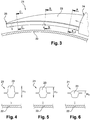
- This device 21, illustrated in figures 3 and 4 to 6 comprises tubes 23 extending circumferentially around the outer casing 22.
- the tube 23 has a section reducing from a first end 24 for supplying fresh air to the tube 23, towards a second end 25 which is circumferentially opposite.
- the figures 4 to 6 represent various sections of the tube of the device of the prior art according to the section planes AA, BB and CC of the figure 3 , respectively. It is noted in these figures, that the dimension of radial extension H1 of the tube 23 in section AA, near the first end 24, is substantially equal to the dimension of radial extension H2 in section BB and greater than the dimension of radial extension H3 of section CC, near the second end 25.
- the air flowing in each tube 23 is gradually heated by the radiation of the housing 22 from the inlet 24 of the tube 23 to the opposite end 25 of the tube 23 so that it is difficult to achieve cooling.
- homogeneous over the entire circumference of the outer casing 22 In fact, the air is colder near the air inlet 24 of the tube 23 since the air in this zone comes directly from the air inlet, for example therefore, the cooling of the housing 22 is more efficient in this area. Conversely, the air is hotter in the circumferential zone remote from the air inlet 24, the cooling of the casing 22 is less effective in this zone.
- the invention aims to remedy these drawbacks in a simple, efficient and inexpensive manner.
- the invention provides a device for cooling an outer annular turbine casing, the device comprising at least one tube extending circumferentially around the outer annular casing and having an air inlet, intended for the routing. cooling air, said tube comprising a radially inner wall provided with cooling air ejection orifices and a radially outer wall disposed axially facing each other, an air inlet manifold , the inlet of the tube opening into said manifold, characterized in that the tube comprises at least one intermediate wall extending over a circumferential portion of the tube from the air inlet, the intermediate wall being located radially between the wall radially internal and the radially external wall, the radially internal wall and the intermediate wall forming a first air supply duct, the radially external wall and the intermediate wall forman t a second air conveying duct extending circumferentially beyond the first air conveying duct, relative to the air inlet.
- the cooling air coming for example from a compressor of a turbomachine, is conveyed both by the first duct and by the second duct before being ejected through the corresponding orifices, located in sight glass to cool.
- the cooling air circulating in each of the ducts is gradually reheated as it passes through the corresponding duct.
- the cooling air located in the second duct is protected from such heating by the presence of the first duct located radially inside the second duct, that is to say radially between the second duct and the housing to be cooled. .
- the cooling air comes from the first duct
- a second angular range comprised for example between 45 and 90 °
- the cooling air comes from the second duct.
- the heating of the cooling air circulating in the second duct is prevented by the presence of the first duct which forms an insulating volume.
- the intermediate wall may extend circumferentially over an angle of between 0 and 45 °, from the air inlet, the radially inner and outer walls may each extend at an angle of between 0 and 90 °, to from the air inlet.
- the air inlet can be formed by one of the ends of the tube.
- the air inlet can open into a manifold, for example.
- the section of the tube may decrease with the circumferential position relative to the air inlet.
- the radial dimension of the cooling device is thus limited as a function of its circumference. It will be noted that the first duct is present only on a portion of the tube located on the side of the air inlet. It is therefore easy to reduce the section of the tube opposite the air inlet.
- the section of the tube and the conduits can be square or rectangular.
- the conduits can be formed with the tube by additive manufacturing in order to facilitate their production.
- the device may include an air inlet manifold, the tube inlet opening into said manifold.
- the manifold may include an air supply orifice, the air opening into said manifold through said air supply orifice.
- Said air supply orifice may be oriented radially or circumferentially.
- the air can open radially into the manifold.
- the air can emerge circumferentially or tangentially into the manifold.
- the device may comprise at least two tubes offset axially with respect to one another, the air inlet of each tube opening into said manifold.
- Each air inlet can be designed to so that the air from the manifold enters circumferentially or tangentially into the corresponding tube.
- the device may comprise at least two tubes extending circumferentially opposite each other, the air inlet of each tube opening into said manifold.
- the invention also relates to an assembly for a turbine, comprising an annular casing and a cooling device of the aforementioned type, located radially outside the casing, the air ejection orifices being oriented towards the casing.
- the invention further relates to a turbine for a turbomachine, comprising an assembly of the aforementioned type.
- the turbine is for example a low pressure turbine.
- the tubes can have identical structures and dimensions.
- the device may include fixing means making it possible to fix the tubes to the casing.
- the figures 7 to 12 illustrate a cooling device 26 of an outer casing 17 according to one embodiment of the invention.
- the device 26 comprises several tubes 27 extending circumferentially and connected to each other by a manifold 28 for the cooling air inlet.
- the cooling device 26 is positioned radially outside the outer annular casing 17 of the turbine, here a low pressure turbine 7.
- the cooling air is for example taken from the outlet of the low pressure compressor 3 or of the high pressure compressor 4.
- the cooling air has a temperature relatively lower than the temperature of the exhaust gases, coming from the combustion chamber 5, which pass through the high pressure turbine 6 and the low pressure turbine 7.
- the temperature of the cooling air is for example between 200 and 300 ° C.
- the tubes 27, sixteen in number in the example illustrated, are distributed in two pairs of eight tubes offset axially from each other, along the axis X.
- the two pairs of tubes 27 extend circumferentially opposite each other, each on one side of the air inlet manifold 28.
- the tubes 27 of the same pair are held together on at least one arm 29 extending axially, three arms 29 in the illustrated embodiment.
- Each arm 29 is fixed relative to the outer annular casing 17.
- Each tube 27 comprises a first end 30 forming an air inlet opening into the air inlet manifold 28, and a second end 31 circumferentially opposite the air inlet. Each tube 27 is closed at its second end 31.
- Each tube 27 comprises a radially inner wall 32, located facing the outer annular casing 17, and a radially outer wall 33. Said walls 32, 33 are arranged axially facing one another. The radially inner wall 32 and the radially outer wall 33 are connected to each other by two side walls 34 extending radially.
- the radially internal wall 32 is provided with ejection orifices 35 allowing the passage of cooling air from the inside of the tube 27 concerned to the outside. More particularly, the cooling air is ejected from the tube 27 through the ejection orifices 35 in the direction of the outer annular casing 17, so as to cool it.
- Each tube 27 further comprises an intermediate wall 36 extending over a circumferential portion of the tube 27 from the air inlet 30.
- the intermediate wall 36 is located radially between the radially inner wall 32 and the radially outer wall 33.
- the intermediate wall 36 has a first end 37 by which it is connected to the air inlet manifold 28, and a second end 38 circumferentially distant from the first end 37, the second end 38 joining the radially inner wall 32.
- the intermediate wall 36 further extends between the two side walls 34.
- a first duct 39 for conveying air is delimited by the radially inner wall 32, the intermediate wall 36 and the side walls 34.
- a second duct 40 for conveying air is delimited by the radially outer wall 33, the wall intermediate 36 and side walls 34.
- Each duct 39, 40 has a square or rectangular section.
- the first duct 39 and the intermediate wall 36 extend from the air inlet 30 over an angle ⁇ 1 taken in a plane perpendicular to the axial direction of the turbomachine of between 0 and 45 °.
- the second duct 40 and the tube 27 extend from the air inlet 30 over an angle ⁇ 2 taken in a plane perpendicular to the axial direction of the turbomachine of between 45 and 90 °.
- the first circumferential zone 41 is defined as the zone between the air inlet 30 of the tube 27 and the junction zone between the intermediate wall 36 and the radially internal wall 32, that is to say extending between 0 ° and ⁇ 1.
- the second circumferential zone 42 is defined as the zone between the junction zone between the intermediate wall 36 and the radially internal wall 32 and the second end 31 of the tube 27, that is to say extending between ⁇ 1 and ⁇ 2.
- the second duct 40 is located radially outside the first duct 39 in the first circumferential zone 41.
- the section of the second duct 40 in the second circumferential zone 42 decreases with the angular position with respect to the air inlet 30.
- the section of the second duct 40 is more important at the angle ⁇ 1 than at the angle ⁇ 2.
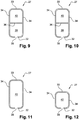
- the figures 9 to 12 illustrate sections of a tube 27 of the cooling device 26, respectively according to the plans AA, BB, CC and DD shown in figure 8 .
- the sections are rectangular with the larger sides of the sections extending radially.
- the tube 27 has a substantially square section, the section plane DD being located between ⁇ 1 and ⁇ 2, closer to the angle ⁇ 2 than to the angle ⁇ 1.
- the cooling air from the manifold 28 enters each tube 27 through its air inlet 30.
- the cooling air is then routed into each duct 39, 40 so as to be ejected from the tubes 27 through the orifices. ejection 35 from the radially lower wall 32.
- the air enters tangentially or circumferentially into the manifold 28, through the inlet 27 ', then the air from the manifold 28 enters tangentially or circumferentially in tubes 27.
- the presence of the first duct 39 radially inside the second duct 40 ensures thermal insulation of the cooling air circulating in the first circumferential zone 41 of the second duct 40.
- the air ejected from the tube 27 into the second circumferential zone 42 maintains a relatively low temperature, which makes it possible to achieve uniform cooling over the entire circumference of the outer casing 17.
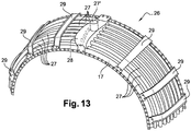
- the figure 13 illustrates an alternative embodiment which differs from that explained above in that the air inlet 27 'of the manifold 28 is directed radially so that the air penetrates radially from the outside towards the interior in the collector 28 before entering the tubes 27.
- Such an embodiment makes it possible to limit the pressure drops within the collector. This improves the efficiency of the cooling.
Description
La présente invention concerne un dispositif de refroidissement de carter annulaire externe de turbine.The present invention relates to a cooling device for an outer annular turbine casing.
Le domaine d'application est notamment celui des moteurs aéronautiques, tels que des turboréacteurs ou des turbopropulseurs d'avion. L'invention est toutefois applicable à d'autres turbomachines, par exemple des turbines industrielles.The field of application is in particular that of aeronautical engines, such as jet engines or airplane turboprop engines. The invention is however applicable to other turbomachines, for example industrial turbines.
La
La turbomachine 1 comporte, de l'amont vers l'aval dans le sens d'écoulement des gaz, une soufflante 2, un compresseur basse pression 3, un compresseur haute pression 4, une chambre de combustion 5, une turbine haute pression 6 et une turbine basse pression 7.The turbomachine 1 comprises, from upstream to downstream in the direction of gas flow, a
L'air issu de la soufflante 2 est divisé en un flux primaire 8 s'écoulant dans une veine annulaire primaire 9, et un flux secondaire 10 s'écoulant dans une veine annulaire secondaire 11 entourant la veine annulaire primaire 10.The air coming from the
Le compresseur basse pression 3, le compresseur haute pression 4, la chambre de combustion 5, la turbine haute pression 6 et la turbine basse pression 7 sont ménagés dans la veine primaire 9.The low-
Le rotor de la turbine haute pression 6 et le rotor du compresseur haute pression 4 sont couplés en rotation par l'intermédiaire d'un premier arbre 12 de manière à former un corps haute pression.The rotor of the
Le rotor de la turbine basse pression 7 et le rotor du compresseur basse pression 3 sont couplés en rotation par l'intermédiaire d'un second arbre 13 de manière à former un corps basse pression, la soufflante 2 pouvant être reliée directement au rotor du compresseur basse pression 3 ou bien par l'intermédiaire d'un train d'engrenage épicycloïdal par exemple.The rotor of the
Classiquement, comme représenté à la
La surface radialement interne 18 de l'anneau 16 peut comporter un revêtement abradable 19 destinée à limiter la circulation d'air parasite entre l'extrémité radialement externe 20 des aubes 15 et l'anneau 16. L'anneau 16 assure, en outre, une fonction de reconstitution de la veine supérieure et évite ainsi toute réintroduction de l'air chaud vers le carter 17.The radially
En fonctionnement, la chaleur des gaz circulant dans la turbine entraîne une dilatation des éléments de la turbine et notamment du carter annulaire externe 17. L'anneau 16, qui est fixé au carter annulaire externe 17, est alors également dilaté, ce qui a pour conséquence d'écarter radialement le revêtement abradable 19 de l'extrémité radialement externe des aubes, ce qui nuit aux performances de la turbomachine 1.In operation, the heat from the gases circulating in the turbine causes expansion of the elements of the turbine and in particular of the outer
Il est alors nécessaire de contrôler la dilatation du carter annulaire externe 17 pour limiter la circulation d'air parasite entre l'extrémité radialement externe 20 des aubes 15 et l'anneau 16.It is then necessary to control the expansion of the outer
Le document
Le document
Les
En fonctionnement, l'air circulant dans chaque tube 23 est chauffé progressivement par le rayonnement du carter 22 depuis l'entrée 24 du tube 23 jusqu'à l'extrémité opposée 25 du tube 23 de sorte qu'il est difficile de réaliser un refroidissement homogène sur toute la circonférence du carter externe 22. En effet, l'air est plus froid à proximité de l'entrée 24 d'air du tube 23 puisque l'air dans cette zone provient directement de l'entrée d'air, par conséquent, le refroidissement du carter 22 est plus efficace dans cette zone. A l'inverse, l'air est plus chaud dans la zone circonférentielle éloignée de l'entrée d'air 24, le refroidissement du carter 22 est moins efficace dans cette zone.In operation, the air flowing in each
D'autres dispositifs de refroidissement sont connus des documents
L'invention vise à remédier à ces inconvénients de façon simple, efficace et peu coûteuse.The invention aims to remedy these drawbacks in a simple, efficient and inexpensive manner.
A cet effet, l'invention propose un dispositif de refroidissement d'un carter annulaire externe de turbine, le dispositif comprenant au moins un tube s'étendant circonférentiellement autour du carter annulaire externe et présentant une entrée d'air, destiné à l'acheminement d'air de refroidissement, ledit tube comportant une paroi radialement interne pourvue d'orifices d'éjection d'air de refroidissement et une paroi radialement externe disposées axialement en regard l'une de l'autre, un collecteur d'entrée d'air, l'entrée du tube débouchant dans ledit collecteur, caractérisé en ce que le tube comprend au moins une paroi intermédiaire s'étendant sur une portion circonférentielle du tube depuis l'entrée d'air, la paroi intermédiaire étant située radialement entre la paroi radialement interne et la paroi radialement externe, la paroi radialement interne et la paroi intermédiaire formant un premier conduit d'acheminement d'air, la paroi radialement externe et la paroi intermédiaire formant un second conduit d'acheminement d'air s'étendant circonférentiellement au-delà du premier conduit d'acheminement d'air, par rapport à l'entrée d'air.To this end, the invention provides a device for cooling an outer annular turbine casing, the device comprising at least one tube extending circumferentially around the outer annular casing and having an air inlet, intended for the routing. cooling air, said tube comprising a radially inner wall provided with cooling air ejection orifices and a radially outer wall disposed axially facing each other, an air inlet manifold , the inlet of the tube opening into said manifold, characterized in that the tube comprises at least one intermediate wall extending over a circumferential portion of the tube from the air inlet, the intermediate wall being located radially between the wall radially internal and the radially external wall, the radially internal wall and the intermediate wall forming a first air supply duct, the radially external wall and the intermediate wall forman t a second air conveying duct extending circumferentially beyond the first air conveying duct, relative to the air inlet.
Ainsi, en fonctionnement, de l'air de refroidissement, issu par exemple d'un compresseur d'une turbomachine, est acheminé à la fois par le premier conduit et par le second conduit avant d'être éjecté par les orifices correspondants, situés en regard du carter à refroidir. L'air de refroidissement circulant dans chacun des conduits est progressivement réchauffé au fur et à mesure qu'il traverse le conduit correspondant. L'air de refroidissement situé dans le second conduit est protégé d'un tel échauffement par la présence du premier conduit situé radialement à l'intérieur du second conduit, c'est-à-dire radialement entre le second conduit et le carter à refroidir.Thus, in operation, the cooling air, coming for example from a compressor of a turbomachine, is conveyed both by the first duct and by the second duct before being ejected through the corresponding orifices, located in sight glass to cool. The cooling air circulating in each of the ducts is gradually reheated as it passes through the corresponding duct. The cooling air located in the second duct is protected from such heating by the presence of the first duct located radially inside the second duct, that is to say radially between the second duct and the housing to be cooled. .
De cette manière, sur une première plage angulaire comprise par exemple entre 0 et 45 ° à partir de l'entrée d'air, l'air de refroidissement est issu du premier conduit, et sur une seconde plage angulaire comprise par exemple entre 45 et 90°, l'air de refroidissement est issu du second conduit. Sur la première plage angulaire, l'échauffement de l'air de refroidissement circulant dans le second conduit est empêché par la présence du premier conduit qui forme un volume isolant.In this way, over a first angular range comprised for example between 0 and 45 ° from the air inlet, the cooling air comes from the first duct, and over a second angular range comprised for example between 45 and 90 °, the cooling air comes from the second duct. On the first angular range, the heating of the cooling air circulating in the second duct is prevented by the presence of the first duct which forms an insulating volume.
La paroi intermédiaire peut s'étendre circonférentiellement sur un angle compris entre 0 et 45°, à partir de l'entrée d'air, les parois radialement interne et externe pouvant s'étendre chacune selon un angle compris entre 0 et 90°, à partir de l'entrée d'air.The intermediate wall may extend circumferentially over an angle of between 0 and 45 °, from the air inlet, the radially inner and outer walls may each extend at an angle of between 0 and 90 °, to from the air inlet.
L'entrée d'air peut être formée par l'une des extrémités du tube. L'entrée d'air peut déboucher dans un collecteur, par exemple.The air inlet can be formed by one of the ends of the tube. The air inlet can open into a manifold, for example.
La section du tube peut diminuer avec la position circonférentielle par rapport à l'entrée d'air.The section of the tube may decrease with the circumferential position relative to the air inlet.
On limite ainsi la dimension radiale du dispositif de refroidissement en fonction de sa circonférence. On notera que le premier conduit n'est présent que sur une portion du tube située du côté de l'entrée d'air. Il est donc aisé de réduire la section du tube à l'opposé de l'entrée d'air.The radial dimension of the cooling device is thus limited as a function of its circumference. It will be noted that the first duct is present only on a portion of the tube located on the side of the air inlet. It is therefore easy to reduce the section of the tube opposite the air inlet.
La section du tube et des conduits peut être carrée ou rectangulaire.The section of the tube and the conduits can be square or rectangular.
Les conduits peuvent être formés avec le tube par fabrication additive afin de faciliter leur réalisation.The conduits can be formed with the tube by additive manufacturing in order to facilitate their production.
Le dispositif peut comprendre un collecteur d'entrée d'air, l'entrée du tube débouchant dans ledit collecteur.The device may include an air inlet manifold, the tube inlet opening into said manifold.
Le collecteur peut comporter un orifice d'amené d'air, l'air débouchant dans ledit collecteur par ledit orifice d'amené d'air. Ledit orifice d'amené d'air peut être orienté radialement ou circonférentiellement.The manifold may include an air supply orifice, the air opening into said manifold through said air supply orifice. Said air supply orifice may be oriented radially or circumferentially.
De cette manière, l'air peut déboucher radialement dans le collecteur. En variante, l'air peut déboucher circonférentiellement ou tangentiellement dans le collecteur.In this way, the air can open radially into the manifold. As a variant, the air can emerge circumferentially or tangentially into the manifold.
Le dispositif peut comprendre au moins deux tubes décalés axialement l'un par rapport à l'autre, l'entrée d'air de chaque tube débouchant dans ledit collecteur. Chaque entrée d'air peut être conçue de façon ce que l'air issu du collecteur entre circonférentiellement ou tangentiellement dans le tube correspondant.The device may comprise at least two tubes offset axially with respect to one another, the air inlet of each tube opening into said manifold. Each air inlet can be designed to so that the air from the manifold enters circumferentially or tangentially into the corresponding tube.
Le dispositif peut comprendre au moins deux tubes s'étendant circonférentiellement à l'opposé l'un de l'autre, l'entrée d'air de chaque tube débouchant dans ledit collecteur.The device may comprise at least two tubes extending circumferentially opposite each other, the air inlet of each tube opening into said manifold.
L'invention concerne également un ensemble pour turbine, comportant un carter annulaire et un dispositif de refroidissement du type précité, situé radialement à l'extérieur du carter, les orifices d'éjection d'air étant orientés vers le carter.The invention also relates to an assembly for a turbine, comprising an annular casing and a cooling device of the aforementioned type, located radially outside the casing, the air ejection orifices being oriented towards the casing.
L'invention concerne en outre une turbine pour turbomachine, comprenant un ensemble du type précité.The invention further relates to a turbine for a turbomachine, comprising an assembly of the aforementioned type.
La turbine est par exemple une turbine basse pression.The turbine is for example a low pressure turbine.
Les tubes peuvent présenter des structures et des dimensions identiques.The tubes can have identical structures and dimensions.
Le dispositif peut comprendre des moyens de fixation permettant de fixer les tubes au carter.The device may include fixing means making it possible to fix the tubes to the casing.
L'invention sera mieux comprise et d'autres détails, caractéristiques et avantages de l'invention apparaîtront à la lecture de la description suivante faite à titre d'exemple non limitatif en référence aux dessins annexés :
- la
figure 1 est une vue schématique en coupe d'une turbomachine ; - la
figure 2 est une vue schématique de détail en coupe d'une partie d'une turbine basse ou haute pression ; - la
figure 3 est une schématique d'un dispositif de refroidissement d'un carter annulaire externe de turbine selon l'art antérieur ; - les
figures 4 à 6 sont des vues en section d'un tube du dispositif, selon les plans A-A, B-B, C-C de lafigure 3 ; - la
figure 7 est une vue en perspective de dessus d'un dispositif de refroidissement d'un carter annulaire externe turbine selon l'invention ; - la
figure 8 est une vue en coupe du dispositif de refroidissement selon l'invention, - les
figures 9 à 12 sont des vues en section d'un tube du dispositif, respectivement selon les plans A-A, B-B, C-C et D-D de lafigure 8 , - la
figure 13 est une vue correspondant à lafigure 7 , illustrant une variante de réalisation de l'invention.
- the
figure 1 is a schematic sectional view of a turbomachine; - the
figure 2 is a detailed schematic sectional view of part of a low or high pressure turbine; - the
figure 3 is a diagram of a device for cooling an outer annular turbine casing according to the prior art; - the
figures 4 to 6 are sectional views of a tube of the device, according to plans AA, BB, CC of thefigure 3 ; - the
figure 7 is a perspective view from above of a device for cooling a turbine outer annular casing according to the invention; - the
figure 8 is a sectional view of the cooling device according to the invention, - the
figures 9 to 12 are sectional views of a tube of the device, respectively according to the plans AA, BB, CC and DD of thefigure 8 , - the
figure 13 is a view corresponding to thefigure 7 , illustrating an alternative embodiment of the invention.
Dans la description détaillée, les éléments de la turbomachine 1 cités en référence aux
Les
Le dispositif 26 comprend plusieurs tubes 27 s'étendant circonférentiellement et reliés les uns aux autres par un collecteur 28 d'entrée d'air de refroidissement. Le dispositif de refroidissement 26 est positionné radialement à l'extérieur du carter annulaire externe 17 de la turbine, ici une turbine basse pression 7.The
L'air de refroidissement est par exemple prélevé en sortie du compresseur basse pression 3 ou du compresseur haute pression 4. L'air de refroidissement a une température relativement inférieure à la température des gaz d'échappement, issus de la chambre de combustion 5, qui traversent la turbine haute pression 6 et la turbine basse pression 7. La température de l'air de refroidissement est par exemple comprise entre 200 et 300 °C.The cooling air is for example taken from the outlet of the
Les tubes 27, au nombre de seize dans l'exemple illustré, sont répartis en deux paires de huit tubes décalées axialement les uns des autres, le long de l'axe X. Les deux paires de tubes 27 s'étendent circonférentiellement à l'opposé l'une de l'autre, chacune d'un côté du collecteur 28 d'entrée d'air.The
Les tubes 27 d'une même paire sont maintenus ensemble sur au moins un bras 29 s'étendant axialement, trois bras 29 dans la forme de réalisation illustrée. Chaque bras 29 est fixe par rapport au carter annulaire externe 17.The
Chaque tube 27 comprend une première extrémité 30 formant une entrée d'air débouchant dans le collecteur 28 d'entrée d'air, et une seconde extrémité 31 circonférentiellement opposée à l'entrée d'air. Chaque tube 27 est fermé à sa seconde extrémité 31.Each
Chaque tube 27 comprend une paroi radialement interne 32, située en regard du carter annulaire externe 17, et une paroi radialement externe 33. Lesdites parois 32, 33 sont disposées axialement en regard l'une de l'autre. La paroi radialement interne 32 et la paroi radialement externe 33 sont reliées l'une à l'autre par deux parois latérales 34 s'étendant radialement.Each
La paroi radialement interne 32 est pourvue d'orifices d'éjection 35 permettant le passage d'air de refroidissement depuis l'intérieur du tube 27 concerné vers l'extérieur. Plus particulièrement, l'air de refroidissement est éjecté du tube 27 par les orifices d'éjection 35 en direction du carter annulaire externe 17, de manière à le refroidir.The radially
Chaque tube 27 comprend en outre une paroi intermédiaire 36 s'étendant sur une portion circonférentielle du tube 27 depuis l'entrée d'air 30. La paroi intermédiaire 36 est située radialement entre la paroi radialement interne 32 et la paroi radialement externe 33. La paroi intermédiaire 36 présente une première extrémité 37 par laquelle elle est reliée au collecteur 28 d'entrée d'air, et une seconde extrémité 38 circonférentiellement distante de la première extrémité 37, la seconde extrémité 38 joignant la paroi radialement interne 32. La paroi intermédiaire 36 s'étend en outre entre les deux parois latérales 34.Each
Un premier conduit 39 d'acheminement d'air est délimité par la paroi radialement interne 32, la paroi intermédiaire 36 et les parois latérales 34. Un second conduit 40 d'acheminement d'air est délimité par la paroi radialement externe 33, la paroi intermédiaire 36 et les parois latérales 34.A
Chaque conduit 39, 40 présente une section carrée ou rectangulaire.Each
Le premier conduit 39 et la paroi intermédiaire 36 s'étendent à partir de l'entrée d'air 30 sur un angle α1 pris dans un plan perpendiculaire à la direction axiale de la turbomachine compris entre 0 et 45 °.The
Le second conduit 40 et le tube 27 s'étendent à partir de l'entrée d'air 30 sur un angle α2 pris dans un plan perpendiculaire à la direction axiale de la turbomachine compris entre 45 et 90 °.The
On définit par première zone circonférentielle 41 la zone comprise entre l'entrée d'air 30 du tube 27 et la zone de jonction entre la paroi intermédiaire 36 et la paroi radialement interne 32, c'est-à-dire s'étendant entre 0° et α1.The first circumferential zone 41 is defined as the zone between the
On définit par seconde zone circonférentielle 42 la zone comprise entre la zone de jonction entre la paroi intermédiaire 36 et la paroi radialement interne 32 et la seconde extrémité 31 du tube 27, c'est-à-dire s'étendant entre α1 et α2.The
Le second conduit 40 est situé radialement à l'extérieur du premier conduit 39 dans la première zone circonférentielle 41.The
Comme représenté sur la
Les
Aux
Les sections A-A et B-B, sur les
Enfin, à la
En fonctionnement, l'air de refroidissement issu du collecteur 28 entre dans chaque tube 27 par son entrée d'air 30. L'air de refroidissement est alors acheminé dans chaque conduit 39, 40 de sorte à être éjecté des tubes 27 par les orifices d'éjection 35 de la paroi radialement inférieure 32. En particulier, dans cette forme de réalisation, l'air pénètre tangentiellement ou circonférentiellement dans le collecteur 28, par l'entrée 27', puis l'air du collecteur 28 entre tangentiellement ou circonférentiellement dans les tubes 27.In operation, the cooling air from the manifold 28 enters each
L'air éjecté par les orifices 35 vient alors impacter le carter annulaire externe 17 de la turbine basse pression 7 de sorte à le refroidir.The air ejected through the
La présence du premier conduit 39 radialement à l'intérieur du second conduit 40 permet d'assurer une isolation thermique de l'air de refroidissement circulant dans la première zone circonférentielle 41 du second conduit 40.The presence of the
Ainsi, l'air éjecté du tube 27 dans la seconde zone circonférentielle 42 conserve une température relativement faible, ce qui permet de réaliser un refroidissement homogène sur toute la circonférence du carter externe 17.Thus, the air ejected from the
La
Claims (9)
- A device (26) for cooling an annular outer turbine (7) casing (17), the device (26) comprising at least one tube (27) extending circumferentially around the annular outer casing (17) and having an air inlet (30) intended for conveying cooling air, said tube (27) having a radially inner wall (32) provided with cooling air discharge openings (35) and a radially outer wall (33) arranged axially opposite each other, an air inlet manifold (28), the inlet (30) of the tube (27) opening into said manifold (28), characterized in that the tube (27) comprises at least one intermediate wall (36) extending over a circumferential portion of the tube (27) from the air inlet (30), the intermediate wall (36) being located radially between the radially inner wall (32) and the radially outer wall (33), the radially inner wall (32) and the intermediate wall (36) forming a first air conveying duct (39), the radially outer wall (33) and the intermediate wall (36) forming a second air conveying duct (40) extending circumferentially beyond the first air conveying duct (39), relative to the air inlet (30).
- A device (26) according to claim 1, wherein the intermediate wall (36) extends circumferentially over an angle between 0 and 45° from the air inlet (30), the radially inner and outer walls (32, 33) each extending at an angle between 0 and 90° from the air inlet (30).
- A device (26) according to claim 1 or 2, wherein the cross-section of the tube (27) decreases with a circumferential position relative to the air inlet (30).
- A device (26) according to one of claims 1 to 3, wherein the cross-section of the tube (27) and the ducts (39, 40) is square or rectangular.
- A device (26) according to one of claims 1 to 4, characterized in that the ducts (39, 40) are additively manufactured with the tube (27).
- A device (26) according to one of claims 1 to 5, wherein it comprises at least two tubes (27) axially offset from each other, the air inlet (30) of each tube (27) opening into said manifold (28).
- A device (26) according to claim 6, wherein it comprises at least two tubes (27) extending circumferentially opposite each other, the air inlet (30) of each tube opening into said manifold (28).
- A turbine assembly (7), comprising an annular casing (17) and a cooling device (26) according to one of claims 1 to 7, located radially outside the casing (17), the air discharge openings (35) being oriented towards the casing (17).
- A turbine (7) for a turbomachine, comprising an assembly according to claim 8.
Applications Claiming Priority (2)
| Application Number | Priority Date | Filing Date | Title |
|---|---|---|---|
| FR1755411A FR3067751B1 (en) | 2017-06-15 | 2017-06-15 | COOLING DEVICE FOR AN EXTERNAL TURBINE ANNULAR CASTER |
| PCT/FR2018/051284 WO2018229385A1 (en) | 2017-06-15 | 2018-06-04 | Device for cooling an annular outer turbine casing |
Publications (2)
| Publication Number | Publication Date |
|---|---|
| EP3638886A1 EP3638886A1 (en) | 2020-04-22 |
| EP3638886B1 true EP3638886B1 (en) | 2021-01-06 |
Family
ID=59521102
Family Applications (1)
| Application Number | Title | Priority Date | Filing Date |
|---|---|---|---|
| EP18749416.6A Active EP3638886B1 (en) | 2017-06-15 | 2018-06-04 | Cooling device for an annular external casing of a turbine |
Country Status (5)
| Country | Link |
|---|---|
| US (1) | US11542833B2 (en) |
| EP (1) | EP3638886B1 (en) |
| CN (1) | CN110753782B (en) |
| FR (1) | FR3067751B1 (en) |
| WO (1) | WO2018229385A1 (en) |
Families Citing this family (2)
| Publication number | Priority date | Publication date | Assignee | Title |
|---|---|---|---|---|
| FR3097008B1 (en) * | 2019-06-04 | 2022-03-11 | Safran Aircraft Engines | Device for cooling by air jets a turbine casing and turbomachine comprising such a device |
| FR3105983B1 (en) * | 2020-01-08 | 2022-01-07 | Safran Aircraft Engines | Device for cooling a crankcase of a turbomachine |
Family Cites Families (7)
| Publication number | Priority date | Publication date | Assignee | Title |
|---|---|---|---|---|
| DE3540943A1 (en) * | 1985-11-19 | 1987-05-21 | Mtu Muenchen Gmbh | GAS TURBINE JET ENGINE IN MULTI-SHAFT, TWO-STREAM DESIGN |
| DE3909369A1 (en) * | 1988-03-31 | 1989-10-26 | Gen Electric | GAS TURBINE GAP CONTROL |
| US5205115A (en) * | 1991-11-04 | 1993-04-27 | General Electric Company | Gas turbine engine case counterflow thermal control |
| FR2766232B1 (en) * | 1997-07-18 | 1999-08-20 | Snecma | CIRCULAR HOUSING COOLING OR HEATING DEVICE |
| FR2858652B1 (en) * | 2003-08-06 | 2006-02-10 | Snecma Moteurs | DEVICE FOR CONTROLLING PLAY IN A GAS TURBINE |
| DE102005035540A1 (en) * | 2005-07-29 | 2007-02-01 | Mtu Aero Engines Gmbh | Device for active gap control for a turbomachine |
| US8092146B2 (en) * | 2009-03-26 | 2012-01-10 | Pratt & Whitney Canada Corp. | Active tip clearance control arrangement for gas turbine engine |
-
2017
- 2017-06-15 FR FR1755411A patent/FR3067751B1/en active Active
-
2018
- 2018-06-04 CN CN201880038661.XA patent/CN110753782B/en active Active
- 2018-06-04 WO PCT/FR2018/051284 patent/WO2018229385A1/en unknown
- 2018-06-04 EP EP18749416.6A patent/EP3638886B1/en active Active
- 2018-06-04 US US16/623,086 patent/US11542833B2/en active Active
Non-Patent Citations (1)
| Title |
|---|
| None * |
Also Published As
| Publication number | Publication date |
|---|---|
| US11542833B2 (en) | 2023-01-03 |
| CN110753782B (en) | 2022-10-14 |
| WO2018229385A1 (en) | 2018-12-20 |
| EP3638886A1 (en) | 2020-04-22 |
| FR3067751B1 (en) | 2019-07-12 |
| CN110753782A (en) | 2020-02-04 |
| FR3067751A1 (en) | 2018-12-21 |
| US20200182089A1 (en) | 2020-06-11 |
Similar Documents
| Publication | Publication Date | Title |
|---|---|---|
| EP2510284B1 (en) | Turbine engine combustion chamber | |
| FR2930591A1 (en) | OPTIMIZING THE ANGULAR POSITIONING OF A TURBINE DISPENSER OUTSIDE A TURBOMACHINE COMBUSTION CHAMBER | |
| EP3569929B1 (en) | Assembly for a turbine engine combustion chamber | |
| FR2997997A1 (en) | AIR TUBE SUPPORT SUPPORT IN A TURBOMACHINE | |
| FR3016956A1 (en) | HEAT EXCHANGER OF A TURBOMACHINE | |
| EP3318725A1 (en) | Connection assembly for cooling a turbine of a turbine engine | |
| EP3638886B1 (en) | Cooling device for an annular external casing of a turbine | |
| EP2917518B1 (en) | Air exhaust tube holder in a turbomachine | |
| EP3673154B1 (en) | Discharge duct of an intermediate housing hub for an aircraft turbojet engine comprising cooling channels | |
| EP3824221B1 (en) | Assembly for a turbomachine | |
| EP2705219B1 (en) | Turbine nozzle guide vane assembly in a turbomachine | |
| FR3111666A1 (en) | RECOVERED CYCLE AIRCRAFT TURBOMACHINE | |
| FR3030627A1 (en) | SERVITUDE PASSAGE SYSTEM FOR TURBOMACHINE | |
| EP3983725B1 (en) | Assembly for a gas turbine | |
| FR3068732A1 (en) | COOLING DEVICE | |
| WO2019229377A1 (en) | Device for cooling a turbomachine housing | |
| FR3058459A1 (en) | COOLING DEVICE FOR TURBINE OF A TURBOMACHINE | |
| FR3089544A1 (en) | COOLING DEVICE FOR A TURBOMACHINE HOUSING | |
| FR3081924A1 (en) | TURBOMACHINE FOR AN AIRCRAFT COMPRISING A PRESSURIZED FLUID CONDUIT SURROUNDED BY A BRAIDED OR WOVEN METAL SHEATH | |
| FR3105983A1 (en) | Device for cooling a casing of a turbomachine | |
| EP4259916A1 (en) | Turbine engine for an aircraft | |
| FR2999277A1 (en) | Annular internal or external wall for e.g. direct flow combustion chamber, of turboshaft engine, has cooling holes whose drilling axes are directed according to direction of air flow so as to maintain supply of air axially across holes | |
| FR3070058A1 (en) | AIRCRAFT TURBOMACHINE COMPRISING A COOLING ELEMENT IMPROVING CONVECTION COOLING AND PROVIDING AIR JET IMPACT COOLING OF AN ANNULAR COMBUSTION ROOM TERMINAL LINK FLANGE | |
| FR3026436A1 (en) | TURBOMACHINE, SUCH AS A TURBO AIRBORNE OR TURBOPROPULSER |
Legal Events
| Date | Code | Title | Description |
|---|---|---|---|
| STAA | Information on the status of an ep patent application or granted ep patent |
Free format text: STATUS: UNKNOWN |
|
| STAA | Information on the status of an ep patent application or granted ep patent |
Free format text: STATUS: THE INTERNATIONAL PUBLICATION HAS BEEN MADE |
|
| PUAI | Public reference made under article 153(3) epc to a published international application that has entered the european phase |
Free format text: ORIGINAL CODE: 0009012 |
|
| STAA | Information on the status of an ep patent application or granted ep patent |
Free format text: STATUS: REQUEST FOR EXAMINATION WAS MADE |
|
| 17P | Request for examination filed |
Effective date: 20191212 |
|
| AK | Designated contracting states |
Kind code of ref document: A1 Designated state(s): AL AT BE BG CH CY CZ DE DK EE ES FI FR GB GR HR HU IE IS IT LI LT LU LV MC MK MT NL NO PL PT RO RS SE SI SK SM TR |
|
| AX | Request for extension of the european patent |
Extension state: BA ME |
|
| DAV | Request for validation of the european patent (deleted) | ||
| DAX | Request for extension of the european patent (deleted) | ||
| GRAP | Despatch of communication of intention to grant a patent |
Free format text: ORIGINAL CODE: EPIDOSNIGR1 |
|
| STAA | Information on the status of an ep patent application or granted ep patent |
Free format text: STATUS: GRANT OF PATENT IS INTENDED |
|
| INTG | Intention to grant announced |
Effective date: 20201028 |
|
| GRAS | Grant fee paid |
Free format text: ORIGINAL CODE: EPIDOSNIGR3 |
|
| GRAA | (expected) grant |
Free format text: ORIGINAL CODE: 0009210 |
|
| STAA | Information on the status of an ep patent application or granted ep patent |
Free format text: STATUS: THE PATENT HAS BEEN GRANTED |
|
| AK | Designated contracting states |
Kind code of ref document: B1 Designated state(s): AL AT BE BG CH CY CZ DE DK EE ES FI FR GB GR HR HU IE IS IT LI LT LU LV MC MK MT NL NO PL PT RO RS SE SI SK SM TR |
|
| REG | Reference to a national code |
Ref country code: GB Ref legal event code: FG4D Free format text: NOT ENGLISH |
|
| REG | Reference to a national code |
Ref country code: AT Ref legal event code: REF Ref document number: 1352594 Country of ref document: AT Kind code of ref document: T Effective date: 20210115 Ref country code: CH Ref legal event code: EP |
|
| REG | Reference to a national code |
Ref country code: DE Ref legal event code: R096 Ref document number: 602018011671 Country of ref document: DE |
|
| REG | Reference to a national code |
Ref country code: IE Ref legal event code: FG4D Free format text: LANGUAGE OF EP DOCUMENT: FRENCH |
|
| REG | Reference to a national code |
Ref country code: SE Ref legal event code: TRGR |
|
| REG | Reference to a national code |
Ref country code: NL Ref legal event code: MP Effective date: 20210106 |
|
| REG | Reference to a national code |
Ref country code: AT Ref legal event code: MK05 Ref document number: 1352594 Country of ref document: AT Kind code of ref document: T Effective date: 20210106 |
|
| REG | Reference to a national code |
Ref country code: LT Ref legal event code: MG9D |
|
| PG25 | Lapsed in a contracting state [announced via postgrant information from national office to epo] |
Ref country code: HR Free format text: LAPSE BECAUSE OF FAILURE TO SUBMIT A TRANSLATION OF THE DESCRIPTION OR TO PAY THE FEE WITHIN THE PRESCRIBED TIME-LIMIT Effective date: 20210106 Ref country code: GR Free format text: LAPSE BECAUSE OF FAILURE TO SUBMIT A TRANSLATION OF THE DESCRIPTION OR TO PAY THE FEE WITHIN THE PRESCRIBED TIME-LIMIT Effective date: 20210407 Ref country code: FI Free format text: LAPSE BECAUSE OF FAILURE TO SUBMIT A TRANSLATION OF THE DESCRIPTION OR TO PAY THE FEE WITHIN THE PRESCRIBED TIME-LIMIT Effective date: 20210106 Ref country code: BG Free format text: LAPSE BECAUSE OF FAILURE TO SUBMIT A TRANSLATION OF THE DESCRIPTION OR TO PAY THE FEE WITHIN THE PRESCRIBED TIME-LIMIT Effective date: 20210406 Ref country code: LT Free format text: LAPSE BECAUSE OF FAILURE TO SUBMIT A TRANSLATION OF THE DESCRIPTION OR TO PAY THE FEE WITHIN THE PRESCRIBED TIME-LIMIT Effective date: 20210106 Ref country code: PT Free format text: LAPSE BECAUSE OF FAILURE TO SUBMIT A TRANSLATION OF THE DESCRIPTION OR TO PAY THE FEE WITHIN THE PRESCRIBED TIME-LIMIT Effective date: 20210506 Ref country code: NO Free format text: LAPSE BECAUSE OF FAILURE TO SUBMIT A TRANSLATION OF THE DESCRIPTION OR TO PAY THE FEE WITHIN THE PRESCRIBED TIME-LIMIT Effective date: 20210406 |
|
| PG25 | Lapsed in a contracting state [announced via postgrant information from national office to epo] |
Ref country code: AT Free format text: LAPSE BECAUSE OF FAILURE TO SUBMIT A TRANSLATION OF THE DESCRIPTION OR TO PAY THE FEE WITHIN THE PRESCRIBED TIME-LIMIT Effective date: 20210106 Ref country code: PL Free format text: LAPSE BECAUSE OF FAILURE TO SUBMIT A TRANSLATION OF THE DESCRIPTION OR TO PAY THE FEE WITHIN THE PRESCRIBED TIME-LIMIT Effective date: 20210106 Ref country code: LV Free format text: LAPSE BECAUSE OF FAILURE TO SUBMIT A TRANSLATION OF THE DESCRIPTION OR TO PAY THE FEE WITHIN THE PRESCRIBED TIME-LIMIT Effective date: 20210106 Ref country code: RS Free format text: LAPSE BECAUSE OF FAILURE TO SUBMIT A TRANSLATION OF THE DESCRIPTION OR TO PAY THE FEE WITHIN THE PRESCRIBED TIME-LIMIT Effective date: 20210106 |
|
| PG25 | Lapsed in a contracting state [announced via postgrant information from national office to epo] |
Ref country code: IS Free format text: LAPSE BECAUSE OF FAILURE TO SUBMIT A TRANSLATION OF THE DESCRIPTION OR TO PAY THE FEE WITHIN THE PRESCRIBED TIME-LIMIT Effective date: 20210506 |
|
| REG | Reference to a national code |
Ref country code: DE Ref legal event code: R097 Ref document number: 602018011671 Country of ref document: DE |
|
| PG25 | Lapsed in a contracting state [announced via postgrant information from national office to epo] |
Ref country code: EE Free format text: LAPSE BECAUSE OF FAILURE TO SUBMIT A TRANSLATION OF THE DESCRIPTION OR TO PAY THE FEE WITHIN THE PRESCRIBED TIME-LIMIT Effective date: 20210106 Ref country code: CZ Free format text: LAPSE BECAUSE OF FAILURE TO SUBMIT A TRANSLATION OF THE DESCRIPTION OR TO PAY THE FEE WITHIN THE PRESCRIBED TIME-LIMIT Effective date: 20210106 Ref country code: SM Free format text: LAPSE BECAUSE OF FAILURE TO SUBMIT A TRANSLATION OF THE DESCRIPTION OR TO PAY THE FEE WITHIN THE PRESCRIBED TIME-LIMIT Effective date: 20210106 |
|
| PLBE | No opposition filed within time limit |
Free format text: ORIGINAL CODE: 0009261 |
|
| STAA | Information on the status of an ep patent application or granted ep patent |
Free format text: STATUS: NO OPPOSITION FILED WITHIN TIME LIMIT |
|
| PG25 | Lapsed in a contracting state [announced via postgrant information from national office to epo] |
Ref country code: DK Free format text: LAPSE BECAUSE OF FAILURE TO SUBMIT A TRANSLATION OF THE DESCRIPTION OR TO PAY THE FEE WITHIN THE PRESCRIBED TIME-LIMIT Effective date: 20210106 Ref country code: RO Free format text: LAPSE BECAUSE OF FAILURE TO SUBMIT A TRANSLATION OF THE DESCRIPTION OR TO PAY THE FEE WITHIN THE PRESCRIBED TIME-LIMIT Effective date: 20210106 Ref country code: SK Free format text: LAPSE BECAUSE OF FAILURE TO SUBMIT A TRANSLATION OF THE DESCRIPTION OR TO PAY THE FEE WITHIN THE PRESCRIBED TIME-LIMIT Effective date: 20210106 |
|
| 26N | No opposition filed |
Effective date: 20211007 |
|
| PG25 | Lapsed in a contracting state [announced via postgrant information from national office to epo] |
Ref country code: AL Free format text: LAPSE BECAUSE OF FAILURE TO SUBMIT A TRANSLATION OF THE DESCRIPTION OR TO PAY THE FEE WITHIN THE PRESCRIBED TIME-LIMIT Effective date: 20210106 Ref country code: MC Free format text: LAPSE BECAUSE OF FAILURE TO SUBMIT A TRANSLATION OF THE DESCRIPTION OR TO PAY THE FEE WITHIN THE PRESCRIBED TIME-LIMIT Effective date: 20210106 Ref country code: ES Free format text: LAPSE BECAUSE OF FAILURE TO SUBMIT A TRANSLATION OF THE DESCRIPTION OR TO PAY THE FEE WITHIN THE PRESCRIBED TIME-LIMIT Effective date: 20210106 |
|
| REG | Reference to a national code |
Ref country code: CH Ref legal event code: PL |
|
| PG25 | Lapsed in a contracting state [announced via postgrant information from national office to epo] |
Ref country code: SI Free format text: LAPSE BECAUSE OF FAILURE TO SUBMIT A TRANSLATION OF THE DESCRIPTION OR TO PAY THE FEE WITHIN THE PRESCRIBED TIME-LIMIT Effective date: 20210106 |
|
| REG | Reference to a national code |
Ref country code: BE Ref legal event code: MM Effective date: 20210630 |
|
| PG25 | Lapsed in a contracting state [announced via postgrant information from national office to epo] |
Ref country code: LU Free format text: LAPSE BECAUSE OF NON-PAYMENT OF DUE FEES Effective date: 20210604 |
|
| PG25 | Lapsed in a contracting state [announced via postgrant information from national office to epo] |
Ref country code: LI Free format text: LAPSE BECAUSE OF NON-PAYMENT OF DUE FEES Effective date: 20210630 Ref country code: IE Free format text: LAPSE BECAUSE OF NON-PAYMENT OF DUE FEES Effective date: 20210604 Ref country code: CH Free format text: LAPSE BECAUSE OF NON-PAYMENT OF DUE FEES Effective date: 20210630 |
|
| PG25 | Lapsed in a contracting state [announced via postgrant information from national office to epo] |
Ref country code: IS Free format text: LAPSE BECAUSE OF FAILURE TO SUBMIT A TRANSLATION OF THE DESCRIPTION OR TO PAY THE FEE WITHIN THE PRESCRIBED TIME-LIMIT Effective date: 20210506 |
|
| PG25 | Lapsed in a contracting state [announced via postgrant information from national office to epo] |
Ref country code: BE Free format text: LAPSE BECAUSE OF NON-PAYMENT OF DUE FEES Effective date: 20210630 |
|
| PG25 | Lapsed in a contracting state [announced via postgrant information from national office to epo] |
Ref country code: NL Free format text: LAPSE BECAUSE OF NON-PAYMENT OF DUE FEES Effective date: 20210206 Ref country code: CY Free format text: LAPSE BECAUSE OF FAILURE TO SUBMIT A TRANSLATION OF THE DESCRIPTION OR TO PAY THE FEE WITHIN THE PRESCRIBED TIME-LIMIT Effective date: 20210106 |
|
| PG25 | Lapsed in a contracting state [announced via postgrant information from national office to epo] |
Ref country code: HU Free format text: LAPSE BECAUSE OF FAILURE TO SUBMIT A TRANSLATION OF THE DESCRIPTION OR TO PAY THE FEE WITHIN THE PRESCRIBED TIME-LIMIT; INVALID AB INITIO Effective date: 20180604 |
|
| PGFP | Annual fee paid to national office [announced via postgrant information from national office to epo] |
Ref country code: IT Payment date: 20230523 Year of fee payment: 6 Ref country code: FR Payment date: 20230523 Year of fee payment: 6 Ref country code: DE Payment date: 20230523 Year of fee payment: 6 |
|
| PGFP | Annual fee paid to national office [announced via postgrant information from national office to epo] |
Ref country code: SE Payment date: 20230523 Year of fee payment: 6 |
|
| PGFP | Annual fee paid to national office [announced via postgrant information from national office to epo] |
Ref country code: GB Payment date: 20230523 Year of fee payment: 6 |
|
| PG25 | Lapsed in a contracting state [announced via postgrant information from national office to epo] |
Ref country code: MK Free format text: LAPSE BECAUSE OF FAILURE TO SUBMIT A TRANSLATION OF THE DESCRIPTION OR TO PAY THE FEE WITHIN THE PRESCRIBED TIME-LIMIT Effective date: 20210106 |