EP3638592B1 - Container bottom base provided with a bi-concave arch - Google Patents
Container bottom base provided with a bi-concave arch Download PDFInfo
- Publication number
- EP3638592B1 EP3638592B1 EP18728192.8A EP18728192A EP3638592B1 EP 3638592 B1 EP3638592 B1 EP 3638592B1 EP 18728192 A EP18728192 A EP 18728192A EP 3638592 B1 EP3638592 B1 EP 3638592B1
- Authority
- EP
- European Patent Office
- Prior art keywords
- container
- concave arch
- reinforcing grooves
- container according
- peripheral
- Prior art date
- Legal status (The legal status is an assumption and is not a legal conclusion. Google has not performed a legal analysis and makes no representation as to the accuracy of the status listed.)
- Active
Links
Images

Classifications
-
- B—PERFORMING OPERATIONS; TRANSPORTING
- B65—CONVEYING; PACKING; STORING; HANDLING THIN OR FILAMENTARY MATERIAL
- B65D—CONTAINERS FOR STORAGE OR TRANSPORT OF ARTICLES OR MATERIALS, e.g. BAGS, BARRELS, BOTTLES, BOXES, CANS, CARTONS, CRATES, DRUMS, JARS, TANKS, HOPPERS, FORWARDING CONTAINERS; ACCESSORIES, CLOSURES, OR FITTINGS THEREFOR; PACKAGING ELEMENTS; PACKAGES
- B65D1/00—Rigid or semi-rigid containers having bodies formed in one piece, e.g. by casting metallic material, by moulding plastics, by blowing vitreous material, by throwing ceramic material, by moulding pulped fibrous material or by deep-drawing operations performed on sheet material
- B65D1/02—Bottles or similar containers with necks or like restricted apertures, designed for pouring contents
- B65D1/0223—Bottles or similar containers with necks or like restricted apertures, designed for pouring contents characterised by shape
- B65D1/0261—Bottom construction
- B65D1/0284—Bottom construction having a discontinuous contact surface, e.g. discrete feet
-
- B—PERFORMING OPERATIONS; TRANSPORTING
- B65—CONVEYING; PACKING; STORING; HANDLING THIN OR FILAMENTARY MATERIAL
- B65D—CONTAINERS FOR STORAGE OR TRANSPORT OF ARTICLES OR MATERIALS, e.g. BAGS, BARRELS, BOTTLES, BOXES, CANS, CARTONS, CRATES, DRUMS, JARS, TANKS, HOPPERS, FORWARDING CONTAINERS; ACCESSORIES, CLOSURES, OR FITTINGS THEREFOR; PACKAGING ELEMENTS; PACKAGES
- B65D1/00—Rigid or semi-rigid containers having bodies formed in one piece, e.g. by casting metallic material, by moulding plastics, by blowing vitreous material, by throwing ceramic material, by moulding pulped fibrous material or by deep-drawing operations performed on sheet material
- B65D1/02—Bottles or similar containers with necks or like restricted apertures, designed for pouring contents
- B65D1/0223—Bottles or similar containers with necks or like restricted apertures, designed for pouring contents characterised by shape
- B65D1/0261—Bottom construction
-
- B—PERFORMING OPERATIONS; TRANSPORTING
- B65—CONVEYING; PACKING; STORING; HANDLING THIN OR FILAMENTARY MATERIAL
- B65D—CONTAINERS FOR STORAGE OR TRANSPORT OF ARTICLES OR MATERIALS, e.g. BAGS, BARRELS, BOTTLES, BOXES, CANS, CARTONS, CRATES, DRUMS, JARS, TANKS, HOPPERS, FORWARDING CONTAINERS; ACCESSORIES, CLOSURES, OR FITTINGS THEREFOR; PACKAGING ELEMENTS; PACKAGES
- B65D2501/00—Containers having bodies formed in one piece
- B65D2501/0009—Bottles or similar containers with necks or like restricted apertures designed for pouring contents
- B65D2501/0018—Ribs
- B65D2501/0036—Hollow circonferential ribs
Definitions
- the invention relates to improvements made to containers, in particular bottles or jars, obtainable by blowing, blow-molding or stretch blow-molding of preforms made of thermoplastic material such as PET (polyethylene terephthalate), PE (polyethylene), PEF (polyethylene furanoate) or other suitable thermoplastic material.
- thermoplastic material such as PET (polyethylene terephthalate), PE (polyethylene), PEF (polyethylene furanoate) or other suitable thermoplastic material.
- Manufacturing of containers by blow-molding ordinarily consists of inserting, into a mold with the imprint of the container, a preform previously heated to a temperature above the glass transition temperature of the material, and of injecting into the preform a fluid (particularly a gas such as air but it can also be an incompressible fluid such as water) under pressure.
- the blowing can be completed by a preliminary stretching of the preform by means of a sliding rod.
- Such containers have a body extending between, at the top, a neck and, at the bottom, a base adapted for withstanding without marked deformation the hydrostatic pressure due to the liquid column which rises above them.
- Containers intended to contain a still liquid are, in the majority of cases, provided with a rounded bottom base in the general form of a spherical cap having a concavity turned outwards and of relatively small height.
- Such bases are often provided with substantially radially radiating ribs which are distributed around a central recess, said ribs possibly having various shapes and optionally extending possibly onto the lower part of the wall of the body in order to reinforce the foundation (peripheral zone with which the base rests on a support).
- Such bases in addition to withstanding the hydrostatic pressure due to the liquid column which rises above them, should offer sufficient resistance to withstand any additional stress, even though small, that may be due for example to an internal excess pressure due to storage conditions.
- the temperature of the contents can reach or exceed 50°C., and the increase in pressure caused by the expansion of the contents exceeds the threshold beyond which the base reverses.
- the container then becomes unstable, with the increased risk of collapse of the whole pallet.
- the container when the container is stored in a cooler at temperatures at which the contents freeze, the expansion induced by the solidification may cause the bottom base to reverse, the container thus becoming unstable.
- thermoplastic containers such as PET constantly seek to make the containers lighter, which is reflected in, among other things, a lightening of the bases of the containers. For this reason, bottom bases of containers having shapes which were satisfactory a few years ago are no longer suitable, because of the perceptible reduction in the quantity of material used and it is not.
- Document US2014/175043 A1 discloses a plastic container having a main body having a main body with a peripheral wall extending around in a circumferential direction of the plastic container, and a container base adjoining the main body that has a central region and a plurality of reinforcing ribs.
- the ribs are starting from the central region and extend in the direction of the circumferential wall.
- a base region extends from the central region to an actual base surface. The base region is curved inwards like a dome.
- Document US 3935955 A proposes a bottom structure for plastic bottles (suitable for containing carbonated beverages) in which the outer surface of the bottom structure is formed with a central concave dome portion and a number of radial foot portions extending axially outwardly.
- the radial profile of each foot portion is a curve which merges with the dome portion and with the side wall of the container and which comprises a plurality of tangential arcs in series.
- an improved mold for forming such bottom structures.
- Document US 2015/136727 A discloses a container made of plastic, provided with a body and with a bottom extending from an end of the body, the bottom having a peripheral seat defining a seating plane, a central zone at an inner area of the bottom surrounding a pellet and corresponding to a zone of injection of the material of a preform used to produce the container, a concave arch extending from the central zone to the peripheral seat, a series of principal reinforcing grooves extending radially from the central zone to at least the peripheral seat.
- the arch has two concentric regions, including a central region and a peripheral region, separated by a median axial step that extends annularly continuously around the central zone, so that the central region is raised with respect to the peripheral region.
- a first objective of the present invention is to propose a container for which the optimized structure and geometry of the base gives it a good compromise between blowability, lightness and rigidity.
- a second objective is to propose a container, the base of which offers good resistance to reversal, denting (nonreversible local deformation) and palletization, and which, under high conditions of pressure and/or internal volume, remains stable.
- the invention provides a container according to Claim 1, said container being made of plastic and comprising a body and a bottom base in which the bottom base has a concave arch presenting two annular tangentially continuous concentric regions, one of said region having a radius of curvature smaller than the other one.
- the bottom base of the container of the invention comprises a peripheral seat defining a laying plane; a concave arch which extends from the periphery of a central zone of the bottom base to the peripheral seat, said concave arch having a rounded general shape with a concavity turned towards the outside of the container; and a series of principal reinforcing grooves which extend radially from the central zone to at least the peripheral seat.
- the concave arch has two annular tangentially continuous concentric regions, i.e. a central region and a peripheral region, said annular tangentially concentric continuous regions being in continuity with each other and said regions presenting two different radii of curvature, the peripheral region having a radius of curvature smaller than the one of the central region.
- the proposed bottom base makes it possible to propose bottles having higher performances than tested bottles currently on the market.
- Said higher performances include resistance to denting, resistance to internal pressure and pallets stability.
- the central region of the concave arch has a height that is defined as the height between the laying plane and the virtual intersection of the central region of the concave arch and the main axis of the container.
- said height of the central region of the concave arch may be comprised within the range from 3 mm to 10 mm.
- the central region of the concave arch has a radius of curvature having its center on the main axis of the container.
- the radius of the peripheral region of the concave arch is comprised within the range from 3 mm to 8 mm.
- the center of the circle presenting said radius may not be centered on the seating plane.
- This peripheral region of the concave arch participates to increasing the rigidity of the bottom base for small internal pressures induced by heat during storage or transportation.
- the peripheral seat of the bottom base of the container of the invention comprises a width comprised within the range from 0.7 mm to 5 mm. These value of the peripheral seat width are smaller than usual values encountered in bottom base of the art. This feature participates to the resistance of the bottom base to reversal due to internal pressure.
- the principal reinforcing grooves of the bottom base have a curvature that is tangentially continuous and concentric to the central and peripheral regions of the concave arch.
- This type of arrangement allows having better performances than the current tested bottom bases for a 5 mm deflection top load test.
- the performance are improved by 10 to 15 %.
- the principal reinforcing grooves have a depth comprised within the range from 1.5 mm to 3.5 mm.
- the principal reinforcing grooves with the proposed depth allow to push the boundaries of rupture of the grooves when pressure is applied. Better results in comparison to the tested bottom base have been obtained with a score of +25 %.
- the principal reinforcing grooves have an open angle comprised within the range from 40° to 80°.
- the bottom base of the claimed container comprise intermediate reinforcing grooves which are each interposed between two principle reinforcing grooves.
- intermediate reinforcing grooves allows diminishing the surface with flat structure on the base thereby reinforcing the bottom base of the container to resist pressure and denting.
- the intermediate reinforcing grooves extend from the central region of the concave arch to at least the peripheral seat.
- the bottom base comprises a fully structured surface contributes to avoiding reversal of the bottom base and to resisting to pressure.
- the principal and/or intermediate reinforcing grooves extend locally over the peripheral seat and rise up over the bottom base of the container to the body of the container.
- This feature allows having good resistance to lateral denting.
- the principal and/or intermediate reinforcing grooves rise up to the body of the container to a height comprised within the range from 9 to 15 mm with respect to the laying plan.
- the central zone has a semi spherical shape having a radius of 8 to 15 mm centered on the container axis and has a height with respect to the laying plan comprised within the range from 6 to 16 mm.
- the central zone with the proposed radius dimensions enables to shatter the amorphous material located at the bottom end of the preform during the blow-molding process and hence participate to a better repartition of the plastic material during the bi orientation operation (stretching and blowing). This has direct effect to the score obtained during the drop tests made on the container.
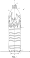
- FIG. 1 shows a general view of a container 1, a bottle in this instance, produced by stretch blow-molding of a preform made of thermoplastic material, for example PET (polyethylene terephthalate) or PEF (polyethylene-furanoate).
- PET polyethylene terephthalate
- PEF polyethylene-furanoate
- Said container 1 comprises, at an upper end, a neck 2, provided with a mouth 3.
- the container 1 comprises in its upper part a shoulder 4 that widens out in the direction opposite to the neck 2, said shoulder 4 being extended by a lateral wall or body 5, of a shape generally cylindrical in revolution around a main axis X of the container 1.
- the container 1 further comprises a bottom 6 which extends, opposite the neck 2, from a lower end of the body 5.
- the bottom 6 comprises a peripheral seat 7 in the form of an annular ridge which extends substantially axially in the extension of the body 5.
- the seat 7 terminates in a laying plane 8 (also called seating plane) perpendicular to the axis X of the container 1, said seating plane 8 defining the lower end of the container 1 and enabling it to be seated upright on a flat surface.
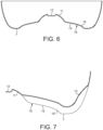
- the peripheral seat 7 comprises a width comprised within the range from 0.7 mm to 5 mm. This width of the peripheral seat 7 is smaller than the usual values of seat width for a bottom base. This specific width of the peripheral seat 7 participate in increasing the resistance of the bottom base 6 to reversal due to pressure. This characteristic is also specifically visible in FIG. 6 .
- D denotes the diameter of the container 1 laying on seating plane 8, the term “diameter” covering not only the case (illustrated) in which the container 1 (and thus the bottom 6) has a circular contour, but also a case in which the container 1 would have a polygonal contour (for example square), in which case the term “diameter” would designate the diameter of the circle in which said polygon is inscribed.
- FIGS. 2 to 7 will be jointly described in the following part.
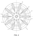
- FIGS 2 and 3 presenting a bottom view and perspective view of the bottom base of container of FIG. 1 integrating the features of the invention, show the bottom base 6 which comprises from its peripheral part 7 to its center : the peripheral seat 7, already described, a concave arch 10, a central zone 11 also called push up and an amorphous pellet 12 resulting from the formation of the preform and located in its center.
- the central zone 11 has a semi spherical shape having a radius of 8 to 15 mm and has a height with respect to the laying plan 8 comprised within the range from 6 to 16 mm.
- the central zone 11 has the function of participating to a better repartition of the plastic material (especially the amorphous plastic material) in the bottom base during the bi-orientation process.
- the concave arch 10 has a rounded general shape. It is in the form of a substantially spherical dome with the concavity turned towards the exterior of the container 1 in the absence of stress, i.e. in the absence of contents in the container 1.
- the arch 10 extends from the seat 7, to the central zone 11 of the bottom 6 forming a boss projecting towards the interior of the container 1.
- the arch 10 has two annular tangentially continuous concentric regions. Said two concentric regions are:
- the two concentric regions 15 and 16 are annularly tangential and in continuity. They have two different radius of curvature.
- the central region 15 of the concave arch 10 has a radius of curvature having its center on the main axis of the container.
- the central region 15 of the concave arch has a height that is defined as the height between the laying plane and the virtual intersection of the central region 15 of the concave arch and the main axis X of the container. This height may be comprised within the range from 3 mm to 10 mm.
- the radius of curvature of the peripheral region 16 of the concave arch is comprised within the range from 3 mm to 8 mm.
- the center of the circle presenting said radius may not be centered on the seating plane 8.
- peripheral region 16 instead of a step as commonly used, allows a better blowability thanks to a better "fingerprinting": during the blowing of the container, the thermoplastic flows better and gets in contact with the mold more easily.
- the peripheral region 16 of the concave arch thus participates in rigidifying the bottom base for additional pressure due to heat during storage or transportation.
- the content of the container exerts a pressure on the bottom base 6 which tends to collapse.
- the concave arch 10 with both the central 15 and peripheral 16 regions improve the resistance by inducing a rigidification of the arch concave 10 in its medial region.
- the deformation of the bottom base 6 at the location of the concave arch 10 is limited to the peripheral region 16.
- the peripheral region 16 will deform towards the laying plane 8 and rejoin the surface of the peripheral seat 7 but the function of the central region 15 of the concave arch 10 is preserved.
- the bottom base 6 comprises a series of principle reinforcing grooves 13.
- Said principal reinforcing grooves 13 are hollow towards the interior of the container 1, and which extend radially from a central zone 11 to at least the peripheral seat 7. According to a preferred embodiment, illustrated in the figures, the principal reinforcing grooves 13 extend beyond the seat 7, rising laterally over a lower part of the body 5 of the container 1.
- the principal grooves 13 extend radially over the entire arch 10, over the peripheral seat 7 and part of the body 5. It will therefore be understood that the seating plane 8 is discontinuous because it is interrupted at each principal groove 13. In the present example, there are five principle grooves 13, but this number could be higher, specifically six or seven for a container with a different volume.
- the principal reinforcing grooves 13 have a curvature that is tangentially continuous and concentric to the central 15 and peripheral 16 regions of the concave arch 10.
- the principal reinforcing grooves 13 have a depth comprised within the range from 1.5 mm to 3.5 mm and an open angle comprised within the range from 40° to 80°.
- the proposed angular range of the open angle ensures a good blowability of the principal reinforcing grooves during the blowing process.
- the base 6 is further provided with a series of intermediate reinforcing grooves 14 located between the principal grooves 13, and which extend locally over the concave arch 10 such that they also contribute to rigidifying the bottom base 6.
- the intermediate reinforcing grooves 14 extend from the central region 15 of the concave arch 10 towards the exterior beyond the peripheral seat 7, rising laterally over a lower part of the body 5, like the principal reinforcing grooves 13.
- the intermediate reinforcing grooves 14 may extend from the central region 15 to the peripheral seat 7 without extending over it.
- the intermediate reinforcing grooves 14 are each interposed between two principle reinforcing grooves 13.
- Both principal 13 and intermediate 14 reinforcing grooves rise up to the body 5 of the container to a height comprised within the range from 9 to 15 mm with respect to the laying plan 8.
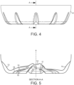
- FIG. 5 which is a cross section of the base according to the invention (as presented in FIGS 2 and 3 ) along the line A-A for FIG. 4 shows, injection point 12, central zone 11 and concave arch 10 with the concave arch 10 comprising two annular tangentially continuous concentric regions: central 15 and peripheral 16 regions.
- the cross section also shows one of the principal reinforcing grooves 13 and one of intermediate reinforcing grooves 14. The difference in position, geometry and shape of principal reinforcing grooves 13 and intermediate reinforcing grooves 14 is clearly represented.
- the container 1 provided with the proposed bottom base 6 offers a good compromise between the mechanical performance (i.e. the ability of the container 1 to resist deformations alone and when palletized and, when they occur, to undergo them in a way that is controlled) and blowability (i.e. the ability of the container 1 to be formed by blowing).
- container and bottle resistance to deformation (reversal and/or denting) and breakage is essential to guarantee product stability and prevent losses during transportation, but also to ensure no negative impact on consumer satisfaction during bottle handling and consumption.
- the bottom base of the container and bottle plays a critical role, in particular for what concerns bottle stability and resistance.
- the objective of the study is to quantify the impact of bottle base weight and type on the global performance (e.g. resistance) of a 12g PET cylindrical bottle having a volume of 50cl as well as on 25.5g PET cylindrical bottle having a volume of 1.5l.
- the proposed bottom base (V4) performs better than the other tested bases for bottles having two different volumes (50cl and 1.5l) for all tested features.
- the initially proposed optimization should be fully acknowledge.
Landscapes
- Engineering & Computer Science (AREA)
- Ceramic Engineering (AREA)
- Mechanical Engineering (AREA)
- Containers Having Bodies Formed In One Piece (AREA)
- Details Of Rigid Or Semi-Rigid Containers (AREA)
- Table Devices Or Equipment (AREA)
- Vessels And Coating Films For Discharge Lamps (AREA)
Description
- The invention relates to improvements made to containers, in particular bottles or jars, obtainable by blowing, blow-molding or stretch blow-molding of preforms made of thermoplastic material such as PET (polyethylene terephthalate), PE (polyethylene), PEF (polyethylene furanoate) or other suitable thermoplastic material.
- Manufacturing of containers by blow-molding ordinarily consists of inserting, into a mold with the imprint of the container, a preform previously heated to a temperature above the glass transition temperature of the material, and of injecting into the preform a fluid (particularly a gas such as air but it can also be an incompressible fluid such as water) under pressure. The blowing can be completed by a preliminary stretching of the preform by means of a sliding rod.
- The dual molecular orientation (bi-orientation) that the material undergoes during blow-molding (axial and radial, respectively parallel and perpendicular to the general axis of the container) gives a certain structural rigidity to the container.
- Such containers have a body extending between, at the top, a neck and, at the bottom, a base adapted for withstanding without marked deformation the hydrostatic pressure due to the liquid column which rises above them.
- Containers intended to contain a still liquid (for example bottles intended to contain drinking water) are, in the majority of cases, provided with a rounded bottom base in the general form of a spherical cap having a concavity turned outwards and of relatively small height. Such bases are often provided with substantially radially radiating ribs which are distributed around a central recess, said ribs possibly having various shapes and optionally extending possibly onto the lower part of the wall of the body in order to reinforce the foundation (peripheral zone with which the base rests on a support).
- Such bases, in addition to withstanding the hydrostatic pressure due to the liquid column which rises above them, should offer sufficient resistance to withstand any additional stress, even though small, that may be due for example to an internal excess pressure due to storage conditions.
- Indeed, when the container is stored in high heat, typically when it is stored on a pallet outdoors in full sun, the temperature of the contents can reach or exceed 50°C., and the increase in pressure caused by the expansion of the contents exceeds the threshold beyond which the base reverses. The container then becomes unstable, with the increased risk of collapse of the whole pallet.
- Similarly, when the container is stored in a cooler at temperatures at which the contents freeze, the expansion induced by the solidification may cause the bottom base to reverse, the container thus becoming unstable.
- In addition to the above issues, manufacturers of thermoplastic containers such as PET constantly seek to make the containers lighter, which is reflected in, among other things, a lightening of the bases of the containers. For this reason, bottom bases of containers having shapes which were satisfactory a few years ago are no longer suitable, because of the perceptible reduction in the quantity of material used and it is not.
- Solutions proposing to increase the mechanical strength of the bottom bases have been envisaged but this artifice, although effective, requires both an increase in material, incompatible with the aforementioned light weighting requirements, and a high blowing pressure reducing thereby the blowability (i.e. the ability of the container to be formed by blowing) of the container.
- Document
US2014/175043 A1 discloses a plastic container having a main body having a main body with a peripheral wall extending around in a circumferential direction of the plastic container, and a container base adjoining the main body that has a central region and a plurality of reinforcing ribs. The ribs are starting from the central region and extend in the direction of the circumferential wall. A base region extends from the central region to an actual base surface. The base region is curved inwards like a dome. - Document
US 3935955 A proposes a bottom structure for plastic bottles (suitable for containing carbonated beverages) in which the outer surface of the bottom structure is formed with a central concave dome portion and a number of radial foot portions extending axially outwardly. The radial profile of each foot portion is a curve which merges with the dome portion and with the side wall of the container and which comprises a plurality of tangential arcs in series. Also disclosed is an improved mold for forming such bottom structures. - Document
US 2015/136727 A discloses a container made of plastic, provided with a body and with a bottom extending from an end of the body, the bottom having a peripheral seat defining a seating plane, a central zone at an inner area of the bottom surrounding a pellet and corresponding to a zone of injection of the material of a preform used to produce the container, a concave arch extending from the central zone to the peripheral seat, a series of principal reinforcing grooves extending radially from the central zone to at least the peripheral seat. The arch has two concentric regions, including a central region and a peripheral region, separated by a median axial step that extends annularly continuously around the central zone, so that the central region is raised with respect to the peripheral region. - Manufacturers have been working for several years to find the best compromise between lightweight, rigidity and resistance of the containers. One option is to work on the optimization of the structure and geometry of the container's base but the solutions proposed by the prior art are not always satisfactory.
- Therefore, a first objective of the present invention is to propose a container for which the optimized structure and geometry of the base gives it a good compromise between blowability, lightness and rigidity.
- A second objective is to propose a container, the base of which offers good resistance to reversal, denting (nonreversible local deformation) and palletization, and which, under high conditions of pressure and/or internal volume, remains stable.
- In this respects, the invention provides a container according to
Claim 1, said container being made of plastic and comprising a body and a bottom base in which the bottom base has a concave arch presenting two annular tangentially continuous concentric regions, one of said region having a radius of curvature smaller than the other one. - Indeed, the bottom base of the container of the invention comprises a peripheral seat defining a laying plane; a concave arch which extends from the periphery of a central zone of the bottom base to the peripheral seat, said concave arch having a rounded general shape with a concavity turned towards the outside of the container; and a series of principal reinforcing grooves which extend radially from the central zone to at least the peripheral seat. According to the invention, the concave arch has two annular tangentially continuous concentric regions, i.e. a central region and a peripheral region, said annular tangentially concentric continuous regions being in continuity with each other and said regions presenting two different radii of curvature, the peripheral region having a radius of curvature smaller than the one of the central region.
- The proposed bottom base makes it possible to propose bottles having higher performances than tested bottles currently on the market. Said higher performances include resistance to denting, resistance to internal pressure and pallets stability.
- Various additional structural characteristics can be provided to the bottom base of the claimed container. These additional characteristics can be provided alone or in combination.
- For instance the central region of the concave arch has a height that is defined as the height between the laying plane and the virtual intersection of the central region of the concave arch and the main axis of the container.
- More specifically, said height of the central region of the concave arch may be comprised within the range from 3 mm to 10 mm.
- According to a further feature, the central region of the concave arch has a radius of curvature having its center on the main axis of the container.
- In addition to the previous characteristics, the radius of the peripheral region of the concave arch is comprised within the range from 3 mm to 8 mm. The center of the circle presenting said radius may not be centered on the seating plane.
- This peripheral region of the concave arch participates to increasing the rigidity of the bottom base for small internal pressures induced by heat during storage or transportation.
- In a particular way, the peripheral seat of the bottom base of the container of the invention comprises a width comprised within the range from 0.7 mm to 5 mm. These value of the peripheral seat width are smaller than usual values encountered in bottom base of the art. This feature participates to the resistance of the bottom base to reversal due to internal pressure.
- According to a possible option, the principal reinforcing grooves of the bottom base have a curvature that is tangentially continuous and concentric to the central and peripheral regions of the concave arch.
- This type of arrangement allows having better performances than the current tested bottom bases for a 5 mm deflection top load test. The performance are improved by 10 to 15 %.
- It also improves the denting resistance and pressure resistance for example, for a pressure up to 1 bar.
- As an additional characteristic, the principal reinforcing grooves have a depth comprised within the range from 1.5 mm to 3.5 mm.
- The principal reinforcing grooves with the proposed depth allow to push the boundaries of rupture of the grooves when pressure is applied. Better results in comparison to the tested bottom base have been obtained with a score of +25 %.
- According to an additional structural feature the principal reinforcing grooves have an open angle comprised within the range from 40° to 80°.
- According to a further possible feature, the bottom base of the claimed container comprise intermediate reinforcing grooves which are each interposed between two principle reinforcing grooves.
- The use of intermediate reinforcing grooves allows diminishing the surface with flat structure on the base thereby reinforcing the bottom base of the container to resist pressure and denting.
- As a possible arrangement, the intermediate reinforcing grooves extend from the central region of the concave arch to at least the peripheral seat.
- The fact that the bottom base comprises a fully structured surface contributes to avoiding reversal of the bottom base and to resisting to pressure.
- As a further option, the principal and/or intermediate reinforcing grooves extend locally over the peripheral seat and rise up over the bottom base of the container to the body of the container.
- This feature allows having good resistance to lateral denting.
- More specifically, the principal and/or intermediate reinforcing grooves rise up to the body of the container to a height comprised within the range from 9 to 15 mm with respect to the laying plan.
- As a further characteristic of the claimed container, it can be mentioned that the central zone has a semi spherical shape having a radius of 8 to 15 mm centered on the container axis and has a height with respect to the laying plan comprised within the range from 6 to 16 mm.
- The central zone with the proposed radius dimensions enables to shatter the amorphous material located at the bottom end of the preform during the blow-molding process and hence participate to a better repartition of the plastic material during the bi orientation operation (stretching and blowing). This has direct effect to the score obtained during the drop tests made on the container.
- Various additional characteristics to the one presented can be provided, alone or in combination with the proposed claimed features.
- The invention is further described with reference to the following examples. It will be appreciated that the invention as claimed is not intended to be limited in any way by these examples.
- Embodiments of the present invention will now be described, by way of examples, with reference to the accompanying figures in which:
-
FIG. 1 is a general view of a container made of plastic; -
FIG. 2 is a bottom view of the container ofFIG. 1 presenting a bottom base according to the invention; -
FIG. 3 is a perspective view showing the bottom of the container ofFIG. 2 ; -
FIG. 4 is an front view of the bottom base of the container ofFIGS. 2 and3 ; -
FIG. 5 is a view in cross section along the line A-A, of the bottom base ofFIG. 4 ; -
FIG. 6 is a simplified view in cross section of the concave arch of the bottom base ofFIGS. 2 and3 . -
FIG. 7 is a detailed cross section view of the principal reinforcing grooves of the bottom base ofFIG. 2 and3 . - As used in this specification, the words "comprises", "comprising", and similar words, are not to be interpreted in an exclusive or exhaustive sense. In other words, they are intended to mean including, but not limited to.
- Any reference to prior art documents in this specification is not to be considered as an admission that such prior art is widely known or forms part of the common general knowledge in the field.
-
FIG. 1 shows a general view of acontainer 1, a bottle in this instance, produced by stretch blow-molding of a preform made of thermoplastic material, for example PET (polyethylene terephthalate) or PEF (polyethylene-furanoate). - Said
container 1 comprises, at an upper end, aneck 2, provided with a mouth 3. In the extension of theneck 2, thecontainer 1 comprises in its upper part ashoulder 4 that widens out in the direction opposite to theneck 2, saidshoulder 4 being extended by a lateral wall orbody 5, of a shape generally cylindrical in revolution around a main axis X of thecontainer 1. - The
container 1 further comprises a bottom 6 which extends, opposite theneck 2, from a lower end of thebody 5. Thebottom 6 comprises aperipheral seat 7 in the form of an annular ridge which extends substantially axially in the extension of thebody 5. Theseat 7 terminates in a laying plane 8 (also called seating plane) perpendicular to the axis X of thecontainer 1, saidseating plane 8 defining the lower end of thecontainer 1 and enabling it to be seated upright on a flat surface. - The
peripheral seat 7 comprises a width comprised within the range from 0.7 mm to 5 mm. This width of theperipheral seat 7 is smaller than the usual values of seat width for a bottom base. This specific width of theperipheral seat 7 participate in increasing the resistance of thebottom base 6 to reversal due to pressure. This characteristic is also specifically visible inFIG. 6 . - In
FIG. 1 , D denotes the diameter of thecontainer 1 laying onseating plane 8, the term "diameter" covering not only the case (illustrated) in which the container 1 (and thus the bottom 6) has a circular contour, but also a case in which thecontainer 1 would have a polygonal contour (for example square), in which case the term "diameter" would designate the diameter of the circle in which said polygon is inscribed. -
FIGS. 2 to 7 will be jointly described in the following part. -
FIGS 2 and3 , presenting a bottom view and perspective view of the bottom base of container ofFIG. 1 integrating the features of the invention, show thebottom base 6 which comprises from itsperipheral part 7 to its center : theperipheral seat 7, already described, aconcave arch 10, acentral zone 11 also called push up and anamorphous pellet 12 resulting from the formation of the preform and located in its center. - The
central zone 11 has a semi spherical shape having a radius of 8 to 15 mm and has a height with respect to thelaying plan 8 comprised within the range from 6 to 16 mm. - As already presented, the
central zone 11 has the function of participating to a better repartition of the plastic material (especially the amorphous plastic material) in the bottom base during the bi-orientation process. - At the center of the
central zone 11 is located theamorphous pellet 12, also called injection point, which corresponds to the zone of injection of the material of the preform used to produce the container and can serve as a centering function during the forming of thecontainer 1 by blowing. - The
concave arch 10 has a rounded general shape. It is in the form of a substantially spherical dome with the concavity turned towards the exterior of thecontainer 1 in the absence of stress, i.e. in the absence of contents in thecontainer 1. The arch 10 extends from theseat 7, to thecentral zone 11 of the bottom 6 forming a boss projecting towards the interior of thecontainer 1. - According to the invention and a visible in the figures, and more particularly in
FIGS. 2 ,4 and6 , the arch 10 has two annular tangentially continuous concentric regions. Said two concentric regions are: - an annular
central region 15, encircling thecentral zone 11 of thebottom base 6; and - an annular
peripheral region 16, encircling thecentral region 15 and continuous with saidcentral region 15. - The two
concentric regions - As presented in
FIG. 6 , presenting a simplified view in cross section of the concave arch 10 (without the reinforcinggrooves 13 and 14), one can visualize the twoconcentric regions peripheral region 16 has a radius of curvature smaller than the one of thecentral region 15. - The
central region 15 of theconcave arch 10 has a radius of curvature having its center on the main axis of the container. - The
central region 15 of the concave arch has a height that is defined as the height between the laying plane and the virtual intersection of thecentral region 15 of the concave arch and the main axis X of the container. This height may be comprised within the range from 3 mm to 10 mm. - The radius of curvature of the
peripheral region 16 of the concave arch is comprised within the range from 3 mm to 8 mm. The center of the circle presenting said radius may not be centered on theseating plane 8. - The presence of the
peripheral region 16, instead of a step as commonly used, allows a better blowability thanks to a better "fingerprinting": during the blowing of the container, the thermoplastic flows better and gets in contact with the mold more easily. - The
peripheral region 16 of the concave arch thus participates in rigidifying the bottom base for additional pressure due to heat during storage or transportation. - Under high internal pressure conditions, the content of the container exerts a pressure on the
bottom base 6 which tends to collapse. Theconcave arch 10 with both the central 15 and peripheral 16 regions improve the resistance by inducing a rigidification of the arch concave 10 in its medial region. - In case of pressure becoming too high, the deformation of the
bottom base 6 at the location of theconcave arch 10 is limited to theperipheral region 16. Theperipheral region 16 will deform towards the layingplane 8 and rejoin the surface of theperipheral seat 7 but the function of thecentral region 15 of theconcave arch 10 is preserved. - As can be seen in the figures, and particularly in
FIGS. 2 and3 , thebottom base 6 comprises a series ofprinciple reinforcing grooves 13. Saidprincipal reinforcing grooves 13 are hollow towards the interior of thecontainer 1, and which extend radially from acentral zone 11 to at least theperipheral seat 7. According to a preferred embodiment, illustrated in the figures, theprincipal reinforcing grooves 13 extend beyond theseat 7, rising laterally over a lower part of thebody 5 of thecontainer 1. - In other words, the
principal grooves 13 extend radially over theentire arch 10, over theperipheral seat 7 and part of thebody 5. It will therefore be understood that theseating plane 8 is discontinuous because it is interrupted at eachprincipal groove 13. In the present example, there are fiveprinciple grooves 13, but this number could be higher, specifically six or seven for a container with a different volume. - As can be seen on
FIG. 7 , theprincipal reinforcing grooves 13 have a curvature that is tangentially continuous and concentric to the central 15 and peripheral 16 regions of theconcave arch 10. - The continuity of the mechanical resistance of the principal reinforcing groove is then ensured.
- In the present proposed embodiment of the invention, the
principal reinforcing grooves 13 have a depth comprised within the range from 1.5 mm to 3.5 mm and an open angle comprised within the range from 40° to 80°. - The proposed angular range of the open angle ensures a good blowability of the principal reinforcing grooves during the blowing process.
- According to a preferred embodiment, the
base 6 is further provided with a series of intermediate reinforcinggrooves 14 located between theprincipal grooves 13, and which extend locally over theconcave arch 10 such that they also contribute to rigidifying thebottom base 6. As represented inFIGS. 2 and3 , the intermediate reinforcinggrooves 14 extend from thecentral region 15 of theconcave arch 10 towards the exterior beyond theperipheral seat 7, rising laterally over a lower part of thebody 5, like theprincipal reinforcing grooves 13. - As another embodiment not represented, the intermediate reinforcing
grooves 14 may extend from thecentral region 15 to theperipheral seat 7 without extending over it. - In the present proposed embodiment of the invention, the intermediate reinforcing
grooves 14 are each interposed between twoprinciple reinforcing grooves 13. - Both principal 13 and intermediate 14 reinforcing grooves rise up to the
body 5 of the container to a height comprised within the range from 9 to 15 mm with respect to thelaying plan 8. -
FIG. 5 which is a cross section of the base according to the invention (as presented inFIGS 2 and3 ) along the line A-A forFIG. 4 shows,injection point 12,central zone 11 andconcave arch 10 with theconcave arch 10 comprising two annular tangentially continuous concentric regions: central 15 and peripheral 16 regions. - The cross section also shows one of the
principal reinforcing grooves 13 and one of intermediate reinforcinggrooves 14. The difference in position, geometry and shape ofprincipal reinforcing grooves 13 and intermediate reinforcinggrooves 14 is clearly represented. - The
container 1 provided with the proposedbottom base 6 offers a good compromise between the mechanical performance (i.e. the ability of thecontainer 1 to resist deformations alone and when palletized and, when they occur, to undergo them in a way that is controlled) and blowability (i.e. the ability of thecontainer 1 to be formed by blowing). - As already mentioned, container and bottle resistance to deformation (reversal and/or denting) and breakage is essential to guarantee product stability and prevent losses during transportation, but also to ensure no negative impact on consumer satisfaction during bottle handling and consumption. In this context the bottom base of the container and bottle plays a critical role, in particular for what concerns bottle stability and resistance.
- The objective of the study is to quantify the impact of bottle base weight and type on the global performance (e.g. resistance) of a 12g PET cylindrical bottle having a volume of 50cl as well as on 25.5g PET cylindrical bottle having a volume of 1.5l.
- The tests have been performed on conventional bottle i.e. on bottles that are not considered as lightweight bottle, but, due to the linearity of the performance as a function of plastic weight used to form the bottle, the results obtained in these comparative tests can be extrapolated to lightweight bottom bases.
- As for the global performance of the base, attention was particularly drawn on the pallets stability and the resistance to denting during transport was assed.
- Four type of bottom bases were compared: Helium, V3, Base S from the competition, and Proposed base (V4) according to the invention.
- Helium, V3 and Base S are bottom bases that are currently on the market.
- A complete pallet, with all bottles being produced with the given base was built,
- For each bottle of the palette, a visual check was assessed on the following features:
- lateral deformation and denting,
- central deformation and denting,
- bottle was angled, inclined
- bottle was not standing up anymore,
- The following table represents the percentages of bottles with defaults in a complete pallet for both tested volumes.
Base Lateral Denting Central Denting Inclined Bottle Falling Bottle Helium 33.6 53.1 24.9 1.3 V4 29.4 44.9 12.3 1.0 Base S from competition 46.7 78.9 30.0 1.8 V3 55.4 46.0 14.4 1.3 - As can be seen in the above table, the proposed bottom base (V4) performs better than the other tested bases for bottles having two different volumes (50cl and 1.5l) for all tested features. The initially proposed optimization should be fully acknowledge.
- Although the invention has been described by way of example, it should be appreciated that variations and modifications may be made without departing from the scope of the invention which is defined by the claims.
-
- X
- container axis
- 1
- Container
- 2
- neck
- 3
- mouth
- 4
- shoulder
- 5
- body
- 6
- bottom base
- 7
- peripheral seat
- 8
- laying plane
- 10
- concave arch
- 11
- central zone (push up)
- 12
- amorphous pellet
- 13
- principal reinforcing grooves
- 14
- intermediate reinforcing grooves
- 15
- central region of concave arch
- 16
- peripheral region of concave arch
- D
- Diameter base
Claims (13)
- Container (1) made of plastic having a main axis (X) being provided with a body (5) and a bottom base (6) extending from a lower end of the body (5), the bottom base (6) comprising:- a peripheral seat (7) defining a laying plane (8);- a concave arch (10) which extends from the periphery of a central zone (11) of the bottom base (6) to the peripheral seat (7), said concave arch (10) having a rounded general shape with a concavity turned towards the outside of the container (1);- a series of principal reinforcing grooves (13) which extend radially from the central zone (11) to at least the peripheral seat (7),characterized in that the concave arch (10) has two annular tangentially continuous concentric regions, i.e. a central region (15) and a peripheral region (16), said annular tangentially continuous concentric regions being in continuity with each other and presenting two different radii of curvature, the peripheral region (16) having a radius of curvature smaller than the one of the central region (15).
- Container according to claim 1, characterized in that the central region (15) of the concave arch (10) has a height comprised within the range of 3 mm to 10 mm, said height being defined as the distance between the laying plane (8) and the virtual intersection of the central region (15) of the concave arch (10) and the main axis (X) of the container.
- Container according to any one of claims 1 or 2, characterized in that the central region (15) of the concave arch (10) has a radius of curvature having its center on the main axis (X) of the container (1).
- Container according to any one of claims 1 or 2, characterized in that the radius of curvature of the peripheral region (16) of the concave arch (10) is comprised within the range from 3 mm to 8 mm.
- Container according to any one of claims 1 to 4, characterized in that the peripheral seat (7) comprises a width comprised within the range from 0.7 mm to 5 mm.
- Container according to any one of claims 1 to 5, characterized in that, in a radial cross-section, the principal reinforcing grooves (13) have a curvature that is tangentially continuous and concentric to the central (15) and peripheral (16) regions of the concave arch (10).
- Container according to any one of claims 1 to 6, characterized in that the principal reinforcing grooves (13) have a depth comprised within the range from 1.5 mm to 3.5 mm.
- Container according to any one of claims 1 to7, characterized in that the principal reinforcing grooves (13) have an open angle comprised within the range from 40° to 80°.
- Container according to any one of claims 1 to 8, characterized in that it further comprises intermediate reinforcing grooves (14) which are each interposed between two of the principal reinforcing grooves (13).
- Container according to claim 9, characterized in that the intermediate reinforcing grooves (14) extend from the central region (15) of the concave arch (10) to at least the peripheral seat (7).
- Container according to any one of claims 1 to 8 and/or according to any of claims 9 or 10, characterized in that the principal (13) and/or intermediate (14) reinforcing grooves extend locally over the peripheral seat (7) and rise up over the bottom base (6) of the container to the body (5) of the container.
- Container according to any one of claims 9 to 11, characterized in that the principal (13) and/or intermediate (14) reinforcing grooves rise up to the body (5) of the container to a height comprised within the range from 9 to 15 mm with respect to the laying plan (8).
- Container according to any one of claims 1 to 12, characterized in that the central zone (11) has a semi spherical shape having a radius of 8 to 15 mm and has a height with respect to the laying plane (8) comprised within the range from 6 to 16 mm.
Applications Claiming Priority (2)
| Application Number | Priority Date | Filing Date | Title |
|---|---|---|---|
| EP17175542 | 2017-06-12 | ||
| PCT/EP2018/065038 WO2018228921A1 (en) | 2017-06-12 | 2018-06-07 | Container bottom base provided with a bi-concave arch |
Publications (2)
| Publication Number | Publication Date |
|---|---|
| EP3638592A1 EP3638592A1 (en) | 2020-04-22 |
| EP3638592B1 true EP3638592B1 (en) | 2023-05-24 |
Family
ID=59055050
Family Applications (1)
| Application Number | Title | Priority Date | Filing Date |
|---|---|---|---|
| EP18728192.8A Active EP3638592B1 (en) | 2017-06-12 | 2018-06-07 | Container bottom base provided with a bi-concave arch |
Country Status (13)
| Country | Link |
|---|---|
| US (1) | US11548678B2 (en) |
| EP (1) | EP3638592B1 (en) |
| JP (2) | JP7748176B2 (en) |
| CN (1) | CN110740941B (en) |
| AR (1) | AR112085A1 (en) |
| AU (1) | AU2018283342B2 (en) |
| BR (1) | BR112019025417A2 (en) |
| CA (1) | CA3066847A1 (en) |
| ES (1) | ES2949274T3 (en) |
| MX (1) | MX2019014202A (en) |
| PL (1) | PL3638592T3 (en) |
| RU (1) | RU2756736C2 (en) |
| WO (1) | WO2018228921A1 (en) |
Families Citing this family (5)
| Publication number | Priority date | Publication date | Assignee | Title |
|---|---|---|---|---|
| JP7454914B2 (en) * | 2019-03-29 | 2024-03-25 | サントリーホールディングス株式会社 | plastic bottle |
| FR3120353B1 (en) * | 2021-03-02 | 2024-07-05 | Sa Des Eaux Minerales Devian Et En Abrege S A E M E | Improved Bottom Bottle |
| USD1085878S1 (en) | 2021-03-25 | 2025-07-29 | Niagara Bottling, Llc | Bottle |
| US12129072B2 (en) * | 2021-11-30 | 2024-10-29 | Pepsico, Inc. | Flexible base for aseptic-fill bottles |
| DE102022120143A1 (en) * | 2022-08-10 | 2024-02-15 | Krones Aktiengesellschaft | Plastic container with drawstring geometry on the bottom area |
Citations (19)
| Publication number | Priority date | Publication date | Assignee | Title |
|---|---|---|---|---|
| US3935955A (en) | 1975-02-13 | 1976-02-03 | Continental Can Company, Inc. | Container bottom structure |
| EP0320151A2 (en) | 1987-12-07 | 1989-06-14 | Sonoco Products Company | PET intermediate article |
| CA2100088A1 (en) | 1991-05-20 | 1992-11-21 | Ralph Allen Gygax | High panel strength retortable plastic containers |
| US6065624A (en) | 1998-10-29 | 2000-05-23 | Plastipak Packaging, Inc. | Plastic blow molded water bottle |
| FR2792286A1 (en) | 1999-04-08 | 2000-10-20 | Perrier Vittel Management Et T | BOTTOM PLASTIC BOTTLE BOTTOM IN TOTAL AND INCLUDING STIFFENERS |
| FR2910438A1 (en) | 2006-12-21 | 2008-06-27 | Eaux Minerales D Evian Saeme S | CHAMPAGNE BOTTLE PLASTIC BOTTLE AND MANUFACTURING METHOD THEREOF |
| FR2919579A1 (en) | 2007-07-30 | 2009-02-06 | Sidel Participations | Plastic container e.g. wide neck polyethylene terephthalate bottle, has amorphous pellet located at center of top of pin that is extended in projection at center of bottom in extension of membrane, where membrane is made of crystalline |
| FR2961492A1 (en) | 2010-06-18 | 2011-12-23 | Sidel Participations | LIGHT CONTAINER WITH REINFORCING BACKGROUND |
| WO2012002164A1 (en) | 2010-06-28 | 2012-01-05 | 日精エー・エス・ビー機械株式会社 | Production method for heat resistant container |
| FR2966130A1 (en) | 2010-10-15 | 2012-04-20 | Sidel Participations | Plastic container e.g. bottle, for containing e.g. milk, has bottom including vault extending from central area of bottom to area near base of bottom, where bottom includes set of stiffeners that extend from vault to positioning plane |
| JP2013203409A (en) | 2012-03-27 | 2013-10-07 | Dainippon Printing Co Ltd | Plastic bottle |
| WO2014038921A1 (en) | 2012-09-10 | 2014-03-13 | 주식회사 효성 | Panel-less container including reinforced bottom part |
| US20140175043A1 (en) | 2012-11-27 | 2014-06-26 | Krones Ag | Plastic container with reinforced base |
| US20150136727A1 (en) | 2012-05-31 | 2015-05-21 | Sidel Participations | Container having a bottom provided with a stepped arch |
| JP2015171913A (en) | 2015-05-20 | 2015-10-01 | ザ コカ・コーラ カンパニーThe Coca‐Cola Company | plastic bottle |
| CN105416744A (en) | 2015-12-02 | 2016-03-23 | 广东星联精密机械有限公司 | Bottom shape structure for increasing pressure in plastic bottle through bottom structure reversing |
| USD757556S1 (en) | 2013-09-25 | 2016-05-31 | Sidel Participations | Bottle |
| US9598201B2 (en) | 2012-04-17 | 2017-03-21 | Sidel Participations | Container comprising an arched base having a star-shaped cross-section |
| US10889402B2 (en) | 2015-12-11 | 2021-01-12 | Amcor Rigid Packaging Usa, Llc | Refillable pet container |
Family Cites Families (15)
| Publication number | Priority date | Publication date | Assignee | Title |
|---|---|---|---|---|
| FR2382373A1 (en) * | 1977-03-02 | 1978-09-29 | Solvay | HOLLOW BODY IN THERMOPLASTIC MATERIAL |
| JPH0644806Y2 (en) * | 1989-07-10 | 1994-11-16 | 株式会社吉野工業所 | Bottle made of synthetic resin |
| JPH07108705B2 (en) * | 1991-07-02 | 1995-11-22 | 東洋製罐株式会社 | Pressure vessel |
| FR2932458B1 (en) * | 2008-06-13 | 2010-08-20 | Sidel Participations | CONTAINER, IN PARTICULAR BOTTLE, IN THERMOPLASTIC MATERIAL EQUIPPED WITH A REINFORCED BACKGROUND |
| US20110049083A1 (en) * | 2009-09-01 | 2011-03-03 | Scott Anthony J | Base for pressurized bottles |
| FR2961180B1 (en) * | 2010-06-11 | 2013-06-07 | Sidel Participations | CONTAINER COMPRISING A VOUTE RIB BOTTOM |
| JP5804709B2 (en) * | 2011-01-24 | 2015-11-04 | サントリーホールディングス株式会社 | Plastic bottle |
| US20140308097A1 (en) | 2011-06-30 | 2014-10-16 | Murata Machinery, Ltd. | Forklift, automatic warehouse using same, and cargo handling method using forklift |
| CH707262A2 (en) * | 2012-11-30 | 2014-05-30 | Alpla Werke | Plastic container. |
| FR2998877B1 (en) * | 2012-11-30 | 2014-12-26 | Sidel Participations | CONTAINER HAVING BACKGROUND PROVIDED WITH A DOUBLE-BREAKDOWN VOUTE |
| JP6537773B2 (en) * | 2014-02-28 | 2019-07-03 | ザ コカ・コーラ カンパニーThe Coca‐Cola Company | Plastic bottle |
| JP6326386B2 (en) | 2014-12-03 | 2018-05-16 | 石塚硝子株式会社 | Resin packaging container bottom structure |
| JP7012417B2 (en) * | 2015-05-20 | 2022-01-28 | サントリーホールディングス株式会社 | Aseptic filling bottle |
| FR3057246B1 (en) * | 2016-10-06 | 2022-12-16 | Sidel Participations | PETALOID BOTTOM WITH BROKEN VALLEY |
| FR3076818B1 (en) * | 2018-01-18 | 2019-12-13 | Sidel Participations | CONTAINER COMPRISING A VOUTE BOTTOM HAVING RIGIDIFICATION BOSSES DISTRIBUTED IN NESTED ANNULAR STRIPS |
-
2018
- 2018-06-07 US US16/621,068 patent/US11548678B2/en active Active
- 2018-06-07 RU RU2019143985A patent/RU2756736C2/en active
- 2018-06-07 PL PL18728192.8T patent/PL3638592T3/en unknown
- 2018-06-07 JP JP2019568390A patent/JP7748176B2/en active Active
- 2018-06-07 CA CA3066847A patent/CA3066847A1/en active Pending
- 2018-06-07 EP EP18728192.8A patent/EP3638592B1/en active Active
- 2018-06-07 AU AU2018283342A patent/AU2018283342B2/en active Active
- 2018-06-07 CN CN201880037354.XA patent/CN110740941B/en active Active
- 2018-06-07 MX MX2019014202A patent/MX2019014202A/en unknown
- 2018-06-07 WO PCT/EP2018/065038 patent/WO2018228921A1/en not_active Ceased
- 2018-06-07 BR BR112019025417-0A patent/BR112019025417A2/en not_active Application Discontinuation
- 2018-06-07 ES ES18728192T patent/ES2949274T3/en active Active
- 2018-06-11 AR ARP180101572A patent/AR112085A1/en active IP Right Grant
-
2023
- 2023-05-08 JP JP2023076719A patent/JP2023100857A/en active Pending
Patent Citations (19)
| Publication number | Priority date | Publication date | Assignee | Title |
|---|---|---|---|---|
| US3935955A (en) | 1975-02-13 | 1976-02-03 | Continental Can Company, Inc. | Container bottom structure |
| EP0320151A2 (en) | 1987-12-07 | 1989-06-14 | Sonoco Products Company | PET intermediate article |
| CA2100088A1 (en) | 1991-05-20 | 1992-11-21 | Ralph Allen Gygax | High panel strength retortable plastic containers |
| US6065624A (en) | 1998-10-29 | 2000-05-23 | Plastipak Packaging, Inc. | Plastic blow molded water bottle |
| FR2792286A1 (en) | 1999-04-08 | 2000-10-20 | Perrier Vittel Management Et T | BOTTOM PLASTIC BOTTLE BOTTOM IN TOTAL AND INCLUDING STIFFENERS |
| FR2910438A1 (en) | 2006-12-21 | 2008-06-27 | Eaux Minerales D Evian Saeme S | CHAMPAGNE BOTTLE PLASTIC BOTTLE AND MANUFACTURING METHOD THEREOF |
| FR2919579A1 (en) | 2007-07-30 | 2009-02-06 | Sidel Participations | Plastic container e.g. wide neck polyethylene terephthalate bottle, has amorphous pellet located at center of top of pin that is extended in projection at center of bottom in extension of membrane, where membrane is made of crystalline |
| FR2961492A1 (en) | 2010-06-18 | 2011-12-23 | Sidel Participations | LIGHT CONTAINER WITH REINFORCING BACKGROUND |
| WO2012002164A1 (en) | 2010-06-28 | 2012-01-05 | 日精エー・エス・ビー機械株式会社 | Production method for heat resistant container |
| FR2966130A1 (en) | 2010-10-15 | 2012-04-20 | Sidel Participations | Plastic container e.g. bottle, for containing e.g. milk, has bottom including vault extending from central area of bottom to area near base of bottom, where bottom includes set of stiffeners that extend from vault to positioning plane |
| JP2013203409A (en) | 2012-03-27 | 2013-10-07 | Dainippon Printing Co Ltd | Plastic bottle |
| US9598201B2 (en) | 2012-04-17 | 2017-03-21 | Sidel Participations | Container comprising an arched base having a star-shaped cross-section |
| US20150136727A1 (en) | 2012-05-31 | 2015-05-21 | Sidel Participations | Container having a bottom provided with a stepped arch |
| WO2014038921A1 (en) | 2012-09-10 | 2014-03-13 | 주식회사 효성 | Panel-less container including reinforced bottom part |
| US20140175043A1 (en) | 2012-11-27 | 2014-06-26 | Krones Ag | Plastic container with reinforced base |
| USD757556S1 (en) | 2013-09-25 | 2016-05-31 | Sidel Participations | Bottle |
| JP2015171913A (en) | 2015-05-20 | 2015-10-01 | ザ コカ・コーラ カンパニーThe Coca‐Cola Company | plastic bottle |
| CN105416744A (en) | 2015-12-02 | 2016-03-23 | 广东星联精密机械有限公司 | Bottom shape structure for increasing pressure in plastic bottle through bottom structure reversing |
| US10889402B2 (en) | 2015-12-11 | 2021-01-12 | Amcor Rigid Packaging Usa, Llc | Refillable pet container |
Also Published As
| Publication number | Publication date |
|---|---|
| AR112085A1 (en) | 2019-09-18 |
| BR112019025417A2 (en) | 2020-06-16 |
| RU2019143985A (en) | 2021-06-28 |
| US20200198827A1 (en) | 2020-06-25 |
| US11548678B2 (en) | 2023-01-10 |
| WO2018228921A1 (en) | 2018-12-20 |
| RU2756736C2 (en) | 2021-10-04 |
| JP2020523261A (en) | 2020-08-06 |
| CN110740941A (en) | 2020-01-31 |
| CN110740941B (en) | 2021-12-07 |
| PL3638592T3 (en) | 2023-07-31 |
| JP7748176B2 (en) | 2025-10-02 |
| JP2023100857A (en) | 2023-07-19 |
| ES2949274T3 (en) | 2023-09-27 |
| CA3066847A1 (en) | 2018-12-20 |
| AU2018283342B2 (en) | 2023-10-05 |
| RU2019143985A3 (en) | 2021-08-24 |
| AU2018283342A1 (en) | 2019-12-05 |
| EP3638592A1 (en) | 2020-04-22 |
| MX2019014202A (en) | 2020-01-27 |
Similar Documents
| Publication | Publication Date | Title |
|---|---|---|
| EP3638592B1 (en) | Container bottom base provided with a bi-concave arch | |
| US9415891B2 (en) | Container having a bottom provided with a stepped arch | |
| US9758271B2 (en) | Container having a bottom provided with a vault with a double indentation | |
| US6672468B1 (en) | Universal container for chemical transportation | |
| US10202221B2 (en) | Combined petaloid base of a container | |
| EP3638593B1 (en) | Container having a bottom base provided with notches | |
| US7032770B2 (en) | Container with structural ribs | |
| CN105050903B (en) | Container with double-arc deformable bottom | |
| US10196168B2 (en) | Container having a bottom provided with a stepped arch | |
| CN101522531A (en) | Bottom of hollow ware obtained by the blow moulding or stretch-blow moulding of a thermoplastic hollow ware preform having such a bottom | |
| US10065766B2 (en) | Container including a ribbed, arched bottom | |
| US9598206B2 (en) | Container including an arched bottom having a square seat | |
| US20170121049A1 (en) | Container provided with a base with bulging beams | |
| JP4935058B2 (en) | Plastic container | |
| US11794939B2 (en) | Thermoplastic material container | |
| US20250376289A1 (en) | Container having an undulating base, and mold base for manufacturing the same | |
| WO2015189127A1 (en) | Bottle and base | |
| JP2024033941A (en) | pressure resistant bottle |
Legal Events
| Date | Code | Title | Description |
|---|---|---|---|
| STAA | Information on the status of an ep patent application or granted ep patent |
Free format text: STATUS: UNKNOWN |
|
| STAA | Information on the status of an ep patent application or granted ep patent |
Free format text: STATUS: THE INTERNATIONAL PUBLICATION HAS BEEN MADE |
|
| PUAI | Public reference made under article 153(3) epc to a published international application that has entered the european phase |
Free format text: ORIGINAL CODE: 0009012 |
|
| STAA | Information on the status of an ep patent application or granted ep patent |
Free format text: STATUS: REQUEST FOR EXAMINATION WAS MADE |
|
| 17P | Request for examination filed |
Effective date: 20200113 |
|
| AK | Designated contracting states |
Kind code of ref document: A1 Designated state(s): AL AT BE BG CH CY CZ DE DK EE ES FI FR GB GR HR HU IE IS IT LI LT LU LV MC MK MT NL NO PL PT RO RS SE SI SK SM TR |
|
| AX | Request for extension of the european patent |
Extension state: BA ME |
|
| DAV | Request for validation of the european patent (deleted) | ||
| DAX | Request for extension of the european patent (deleted) | ||
| STAA | Information on the status of an ep patent application or granted ep patent |
Free format text: STATUS: EXAMINATION IS IN PROGRESS |
|
| 17Q | First examination report despatched |
Effective date: 20210625 |
|
| GRAP | Despatch of communication of intention to grant a patent |
Free format text: ORIGINAL CODE: EPIDOSNIGR1 |
|
| STAA | Information on the status of an ep patent application or granted ep patent |
Free format text: STATUS: GRANT OF PATENT IS INTENDED |
|
| INTG | Intention to grant announced |
Effective date: 20221219 |
|
| RIN1 | Information on inventor provided before grant (corrected) |
Inventor name: TENIERE, VINCENT Inventor name: DABROWSKI, NICOLAS |
|
| GRAS | Grant fee paid |
Free format text: ORIGINAL CODE: EPIDOSNIGR3 |
|
| GRAA | (expected) grant |
Free format text: ORIGINAL CODE: 0009210 |
|
| STAA | Information on the status of an ep patent application or granted ep patent |
Free format text: STATUS: THE PATENT HAS BEEN GRANTED |
|
| AK | Designated contracting states |
Kind code of ref document: B1 Designated state(s): AL AT BE BG CH CY CZ DE DK EE ES FI FR GB GR HR HU IE IS IT LI LT LU LV MC MK MT NL NO PL PT RO RS SE SI SK SM TR |
|
| REG | Reference to a national code |
Ref country code: GB Ref legal event code: FG4D |
|
| REG | Reference to a national code |
Ref country code: CH Ref legal event code: EP |
|
| REG | Reference to a national code |
Ref country code: DE Ref legal event code: R096 Ref document number: 602018050170 Country of ref document: DE |
|
| REG | Reference to a national code |
Ref country code: AT Ref legal event code: REF Ref document number: 1569382 Country of ref document: AT Kind code of ref document: T Effective date: 20230615 |
|
| REG | Reference to a national code |
Ref country code: IE Ref legal event code: FG4D |
|
| P01 | Opt-out of the competence of the unified patent court (upc) registered |
Effective date: 20230527 |
|
| REG | Reference to a national code |
Ref country code: NL Ref legal event code: FP |
|
| REG | Reference to a national code |
Ref country code: GR Ref legal event code: EP Ref document number: 20230401011 Country of ref document: GR Effective date: 20230808 |
|
| REG | Reference to a national code |
Ref country code: LT Ref legal event code: MG9D |
|
| REG | Reference to a national code |
Ref country code: ES Ref legal event code: FG2A Ref document number: 2949274 Country of ref document: ES Kind code of ref document: T3 Effective date: 20230927 |
|
| REG | Reference to a national code |
Ref country code: AT Ref legal event code: MK05 Ref document number: 1569382 Country of ref document: AT Kind code of ref document: T Effective date: 20230524 |
|
| PG25 | Lapsed in a contracting state [announced via postgrant information from national office to epo] |
Ref country code: SE Free format text: LAPSE BECAUSE OF FAILURE TO SUBMIT A TRANSLATION OF THE DESCRIPTION OR TO PAY THE FEE WITHIN THE PRESCRIBED TIME-LIMIT Effective date: 20230524 Ref country code: PT Free format text: LAPSE BECAUSE OF FAILURE TO SUBMIT A TRANSLATION OF THE DESCRIPTION OR TO PAY THE FEE WITHIN THE PRESCRIBED TIME-LIMIT Effective date: 20230925 Ref country code: NO Free format text: LAPSE BECAUSE OF FAILURE TO SUBMIT A TRANSLATION OF THE DESCRIPTION OR TO PAY THE FEE WITHIN THE PRESCRIBED TIME-LIMIT Effective date: 20230824 Ref country code: AT Free format text: LAPSE BECAUSE OF FAILURE TO SUBMIT A TRANSLATION OF THE DESCRIPTION OR TO PAY THE FEE WITHIN THE PRESCRIBED TIME-LIMIT Effective date: 20230524 |
|
| PG25 | Lapsed in a contracting state [announced via postgrant information from national office to epo] |
Ref country code: RS Free format text: LAPSE BECAUSE OF FAILURE TO SUBMIT A TRANSLATION OF THE DESCRIPTION OR TO PAY THE FEE WITHIN THE PRESCRIBED TIME-LIMIT Effective date: 20230524 Ref country code: LV Free format text: LAPSE BECAUSE OF FAILURE TO SUBMIT A TRANSLATION OF THE DESCRIPTION OR TO PAY THE FEE WITHIN THE PRESCRIBED TIME-LIMIT Effective date: 20230524 Ref country code: LT Free format text: LAPSE BECAUSE OF FAILURE TO SUBMIT A TRANSLATION OF THE DESCRIPTION OR TO PAY THE FEE WITHIN THE PRESCRIBED TIME-LIMIT Effective date: 20230524 Ref country code: IS Free format text: LAPSE BECAUSE OF FAILURE TO SUBMIT A TRANSLATION OF THE DESCRIPTION OR TO PAY THE FEE WITHIN THE PRESCRIBED TIME-LIMIT Effective date: 20230924 Ref country code: HR Free format text: LAPSE BECAUSE OF FAILURE TO SUBMIT A TRANSLATION OF THE DESCRIPTION OR TO PAY THE FEE WITHIN THE PRESCRIBED TIME-LIMIT Effective date: 20230524 |
|
| PG25 | Lapsed in a contracting state [announced via postgrant information from national office to epo] |
Ref country code: FI Free format text: LAPSE BECAUSE OF FAILURE TO SUBMIT A TRANSLATION OF THE DESCRIPTION OR TO PAY THE FEE WITHIN THE PRESCRIBED TIME-LIMIT Effective date: 20230524 |
|
| PG25 | Lapsed in a contracting state [announced via postgrant information from national office to epo] |
Ref country code: SK Free format text: LAPSE BECAUSE OF FAILURE TO SUBMIT A TRANSLATION OF THE DESCRIPTION OR TO PAY THE FEE WITHIN THE PRESCRIBED TIME-LIMIT Effective date: 20230524 |
|
| PG25 | Lapsed in a contracting state [announced via postgrant information from national office to epo] |
Ref country code: SM Free format text: LAPSE BECAUSE OF FAILURE TO SUBMIT A TRANSLATION OF THE DESCRIPTION OR TO PAY THE FEE WITHIN THE PRESCRIBED TIME-LIMIT Effective date: 20230524 Ref country code: SK Free format text: LAPSE BECAUSE OF FAILURE TO SUBMIT A TRANSLATION OF THE DESCRIPTION OR TO PAY THE FEE WITHIN THE PRESCRIBED TIME-LIMIT Effective date: 20230524 Ref country code: RO Free format text: LAPSE BECAUSE OF FAILURE TO SUBMIT A TRANSLATION OF THE DESCRIPTION OR TO PAY THE FEE WITHIN THE PRESCRIBED TIME-LIMIT Effective date: 20230524 Ref country code: EE Free format text: LAPSE BECAUSE OF FAILURE TO SUBMIT A TRANSLATION OF THE DESCRIPTION OR TO PAY THE FEE WITHIN THE PRESCRIBED TIME-LIMIT Effective date: 20230524 Ref country code: DK Free format text: LAPSE BECAUSE OF FAILURE TO SUBMIT A TRANSLATION OF THE DESCRIPTION OR TO PAY THE FEE WITHIN THE PRESCRIBED TIME-LIMIT Effective date: 20230524 Ref country code: CZ Free format text: LAPSE BECAUSE OF FAILURE TO SUBMIT A TRANSLATION OF THE DESCRIPTION OR TO PAY THE FEE WITHIN THE PRESCRIBED TIME-LIMIT Effective date: 20230524 |
|
| REG | Reference to a national code |
Ref country code: DE Ref legal event code: R026 Ref document number: 602018050170 Country of ref document: DE |
|
| PG25 | Lapsed in a contracting state [announced via postgrant information from national office to epo] |
Ref country code: MC Free format text: LAPSE BECAUSE OF FAILURE TO SUBMIT A TRANSLATION OF THE DESCRIPTION OR TO PAY THE FEE WITHIN THE PRESCRIBED TIME-LIMIT Effective date: 20230524 |
|
| PG25 | Lapsed in a contracting state [announced via postgrant information from national office to epo] |
Ref country code: MC Free format text: LAPSE BECAUSE OF FAILURE TO SUBMIT A TRANSLATION OF THE DESCRIPTION OR TO PAY THE FEE WITHIN THE PRESCRIBED TIME-LIMIT Effective date: 20230524 |
|
| PG25 | Lapsed in a contracting state [announced via postgrant information from national office to epo] |
Ref country code: LU Free format text: LAPSE BECAUSE OF NON-PAYMENT OF DUE FEES Effective date: 20230607 |
|
| PLBI | Opposition filed |
Free format text: ORIGINAL CODE: 0009260 |
|
| PLAB | Opposition data, opponent's data or that of the opponent's representative modified |
Free format text: ORIGINAL CODE: 0009299OPPO |
|
| PLAX | Notice of opposition and request to file observation + time limit sent |
Free format text: ORIGINAL CODE: EPIDOSNOBS2 |
|
| REG | Reference to a national code |
Ref country code: IE Ref legal event code: MM4A |
|
| PG25 | Lapsed in a contracting state [announced via postgrant information from national office to epo] |
Ref country code: LU Free format text: LAPSE BECAUSE OF NON-PAYMENT OF DUE FEES Effective date: 20230607 |
|
| 26 | Opposition filed |
Opponent name: SIDEL PARTICIPATIONS Effective date: 20240226 |
|
| R26 | Opposition filed (corrected) |
Opponent name: SIDEL PARTICIPATIONS Effective date: 20240226 |
|
| PG25 | Lapsed in a contracting state [announced via postgrant information from national office to epo] |
Ref country code: IE Free format text: LAPSE BECAUSE OF NON-PAYMENT OF DUE FEES Effective date: 20230607 |
|
| PG25 | Lapsed in a contracting state [announced via postgrant information from national office to epo] |
Ref country code: IE Free format text: LAPSE BECAUSE OF NON-PAYMENT OF DUE FEES Effective date: 20230607 |
|
| RAP4 | Party data changed (patent owner data changed or rights of a patent transferred) |
Owner name: SOCIETE DES PRODUITS NESTLE S.A. |
|
| PG25 | Lapsed in a contracting state [announced via postgrant information from national office to epo] |
Ref country code: SI Free format text: LAPSE BECAUSE OF FAILURE TO SUBMIT A TRANSLATION OF THE DESCRIPTION OR TO PAY THE FEE WITHIN THE PRESCRIBED TIME-LIMIT Effective date: 20230524 |
|
| PG25 | Lapsed in a contracting state [announced via postgrant information from national office to epo] |
Ref country code: SI Free format text: LAPSE BECAUSE OF FAILURE TO SUBMIT A TRANSLATION OF THE DESCRIPTION OR TO PAY THE FEE WITHIN THE PRESCRIBED TIME-LIMIT Effective date: 20230524 |
|
| PLBB | Reply of patent proprietor to notice(s) of opposition received |
Free format text: ORIGINAL CODE: EPIDOSNOBS3 |
|
| PG25 | Lapsed in a contracting state [announced via postgrant information from national office to epo] |
Ref country code: BG Free format text: LAPSE BECAUSE OF FAILURE TO SUBMIT A TRANSLATION OF THE DESCRIPTION OR TO PAY THE FEE WITHIN THE PRESCRIBED TIME-LIMIT Effective date: 20230524 |
|
| PG25 | Lapsed in a contracting state [announced via postgrant information from national office to epo] |
Ref country code: BG Free format text: LAPSE BECAUSE OF FAILURE TO SUBMIT A TRANSLATION OF THE DESCRIPTION OR TO PAY THE FEE WITHIN THE PRESCRIBED TIME-LIMIT Effective date: 20230524 |
|
| PGFP | Annual fee paid to national office [announced via postgrant information from national office to epo] |
Ref country code: NL Payment date: 20250516 Year of fee payment: 8 |
|
| PGFP | Annual fee paid to national office [announced via postgrant information from national office to epo] |
Ref country code: PL Payment date: 20250515 Year of fee payment: 8 Ref country code: DE Payment date: 20250429 Year of fee payment: 8 |
|
| PGFP | Annual fee paid to national office [announced via postgrant information from national office to epo] |
Ref country code: GB Payment date: 20250501 Year of fee payment: 8 |
|
| PGFP | Annual fee paid to national office [announced via postgrant information from national office to epo] |
Ref country code: IT Payment date: 20250522 Year of fee payment: 8 Ref country code: BE Payment date: 20250516 Year of fee payment: 8 |
|
| PGFP | Annual fee paid to national office [announced via postgrant information from national office to epo] |
Ref country code: FR Payment date: 20250508 Year of fee payment: 8 |
|
| PGFP | Annual fee paid to national office [announced via postgrant information from national office to epo] |
Ref country code: GR Payment date: 20250516 Year of fee payment: 8 |
|
| PG25 | Lapsed in a contracting state [announced via postgrant information from national office to epo] |
Ref country code: CY Free format text: LAPSE BECAUSE OF FAILURE TO SUBMIT A TRANSLATION OF THE DESCRIPTION OR TO PAY THE FEE WITHIN THE PRESCRIBED TIME-LIMIT; INVALID AB INITIO Effective date: 20180607 |
|
| PGFP | Annual fee paid to national office [announced via postgrant information from national office to epo] |
Ref country code: TR Payment date: 20250602 Year of fee payment: 8 |
|
| PG25 | Lapsed in a contracting state [announced via postgrant information from national office to epo] |
Ref country code: HU Free format text: LAPSE BECAUSE OF FAILURE TO SUBMIT A TRANSLATION OF THE DESCRIPTION OR TO PAY THE FEE WITHIN THE PRESCRIBED TIME-LIMIT; INVALID AB INITIO Effective date: 20180607 |
|
| PGFP | Annual fee paid to national office [announced via postgrant information from national office to epo] |
Ref country code: ES Payment date: 20250702 Year of fee payment: 8 |
|
| PGFP | Annual fee paid to national office [announced via postgrant information from national office to epo] |
Ref country code: CH Payment date: 20250701 Year of fee payment: 8 |
|
| PLCK | Communication despatched that opposition was rejected |
Free format text: ORIGINAL CODE: EPIDOSNREJ1 |
|
| APAH | Appeal reference modified |
Free format text: ORIGINAL CODE: EPIDOSCREFNO |
|
| APBP | Date of receipt of notice of appeal recorded |
Free format text: ORIGINAL CODE: EPIDOSNNOA2O |