EP0320151A2 - PET intermediate article - Google Patents
PET intermediate article Download PDFInfo
- Publication number
- EP0320151A2 EP0320151A2 EP88311164A EP88311164A EP0320151A2 EP 0320151 A2 EP0320151 A2 EP 0320151A2 EP 88311164 A EP88311164 A EP 88311164A EP 88311164 A EP88311164 A EP 88311164A EP 0320151 A2 EP0320151 A2 EP 0320151A2
- Authority
- EP
- European Patent Office
- Prior art keywords
- base portion
- article
- outer peripheral
- radius
- peripheral wall
- Prior art date
- Legal status (The legal status is an assumption and is not a legal conclusion. Google has not performed a legal analysis and makes no representation as to the accuracy of the status listed.)
- Granted
Links
Images


Classifications
-
- B—PERFORMING OPERATIONS; TRANSPORTING
- B65—CONVEYING; PACKING; STORING; HANDLING THIN OR FILAMENTARY MATERIAL
- B65D—CONTAINERS FOR STORAGE OR TRANSPORT OF ARTICLES OR MATERIALS, e.g. BAGS, BARRELS, BOTTLES, BOXES, CANS, CARTONS, CRATES, DRUMS, JARS, TANKS, HOPPERS, FORWARDING CONTAINERS; ACCESSORIES, CLOSURES, OR FITTINGS THEREFOR; PACKAGING ELEMENTS; PACKAGES
- B65D1/00—Containers having bodies formed in one piece, e.g. by casting metallic material, by moulding plastics, by blowing vitreous material, by throwing ceramic material, by moulding pulped fibrous material, by deep-drawing operations performed on sheet material
- B65D1/02—Bottles or similar containers with necks or like restricted apertures, designed for pouring contents
- B65D1/0223—Bottles or similar containers with necks or like restricted apertures, designed for pouring contents characterised by shape
- B65D1/0261—Bottom construction
- B65D1/0276—Bottom construction having a continuous contact surface, e.g. Champagne-type bottom
-
- B—PERFORMING OPERATIONS; TRANSPORTING
- B29—WORKING OF PLASTICS; WORKING OF SUBSTANCES IN A PLASTIC STATE IN GENERAL
- B29B—PREPARATION OR PRETREATMENT OF THE MATERIAL TO BE SHAPED; MAKING GRANULES OR PREFORMS; RECOVERY OF PLASTICS OR OTHER CONSTITUENTS OF WASTE MATERIAL CONTAINING PLASTICS
- B29B11/00—Making preforms
- B29B11/14—Making preforms characterised by structure or composition
-
- B—PERFORMING OPERATIONS; TRANSPORTING
- B29—WORKING OF PLASTICS; WORKING OF SUBSTANCES IN A PLASTIC STATE IN GENERAL
- B29C—SHAPING OR JOINING OF PLASTICS; SHAPING OF MATERIAL IN A PLASTIC STATE, NOT OTHERWISE PROVIDED FOR; AFTER-TREATMENT OF THE SHAPED PRODUCTS, e.g. REPAIRING
- B29C49/00—Blow-moulding, i.e. blowing a preform or parison to a desired shape within a mould; Apparatus therefor
- B29C49/071—Preforms or parisons characterised by their configuration, e.g. geometry, dimensions or physical properties
-
- B—PERFORMING OPERATIONS; TRANSPORTING
- B29—WORKING OF PLASTICS; WORKING OF SUBSTANCES IN A PLASTIC STATE IN GENERAL
- B29C—SHAPING OR JOINING OF PLASTICS; SHAPING OF MATERIAL IN A PLASTIC STATE, NOT OTHERWISE PROVIDED FOR; AFTER-TREATMENT OF THE SHAPED PRODUCTS, e.g. REPAIRING
- B29C49/00—Blow-moulding, i.e. blowing a preform or parison to a desired shape within a mould; Apparatus therefor
- B29C49/42—Component parts, details or accessories; Auxiliary operations
- B29C49/4273—Auxiliary operations after the blow-moulding operation not otherwise provided for
- B29C49/4278—Cutting
-
- B—PERFORMING OPERATIONS; TRANSPORTING
- B65—CONVEYING; PACKING; STORING; HANDLING THIN OR FILAMENTARY MATERIAL
- B65D—CONTAINERS FOR STORAGE OR TRANSPORT OF ARTICLES OR MATERIALS, e.g. BAGS, BARRELS, BOTTLES, BOXES, CANS, CARTONS, CRATES, DRUMS, JARS, TANKS, HOPPERS, FORWARDING CONTAINERS; ACCESSORIES, CLOSURES, OR FITTINGS THEREFOR; PACKAGING ELEMENTS; PACKAGES
- B65D1/00—Containers having bodies formed in one piece, e.g. by casting metallic material, by moulding plastics, by blowing vitreous material, by throwing ceramic material, by moulding pulped fibrous material, by deep-drawing operations performed on sheet material
- B65D1/02—Bottles or similar containers with necks or like restricted apertures, designed for pouring contents
-
- B—PERFORMING OPERATIONS; TRANSPORTING
- B65—CONVEYING; PACKING; STORING; HANDLING THIN OR FILAMENTARY MATERIAL
- B65D—CONTAINERS FOR STORAGE OR TRANSPORT OF ARTICLES OR MATERIALS, e.g. BAGS, BARRELS, BOTTLES, BOXES, CANS, CARTONS, CRATES, DRUMS, JARS, TANKS, HOPPERS, FORWARDING CONTAINERS; ACCESSORIES, CLOSURES, OR FITTINGS THEREFOR; PACKAGING ELEMENTS; PACKAGES
- B65D79/00—Kinds or details of packages, not otherwise provided for
- B65D79/005—Packages having deformable parts for indicating or neutralizing internal pressure-variations by other means than venting
- B65D79/008—Packages having deformable parts for indicating or neutralizing internal pressure-variations by other means than venting the deformable part being located in a rigid or semi-rigid container, e.g. in bottles or jars
- B65D79/0081—Packages having deformable parts for indicating or neutralizing internal pressure-variations by other means than venting the deformable part being located in a rigid or semi-rigid container, e.g. in bottles or jars in the bottom part thereof
-
- B—PERFORMING OPERATIONS; TRANSPORTING
- B29—WORKING OF PLASTICS; WORKING OF SUBSTANCES IN A PLASTIC STATE IN GENERAL
- B29C—SHAPING OR JOINING OF PLASTICS; SHAPING OF MATERIAL IN A PLASTIC STATE, NOT OTHERWISE PROVIDED FOR; AFTER-TREATMENT OF THE SHAPED PRODUCTS, e.g. REPAIRING
- B29C49/00—Blow-moulding, i.e. blowing a preform or parison to a desired shape within a mould; Apparatus therefor
- B29C49/02—Combined blow-moulding and manufacture of the preform or the parison
- B29C2049/023—Combined blow-moulding and manufacture of the preform or the parison using inherent heat of the preform, i.e. 1 step blow moulding
-
- B—PERFORMING OPERATIONS; TRANSPORTING
- B29—WORKING OF PLASTICS; WORKING OF SUBSTANCES IN A PLASTIC STATE IN GENERAL
- B29C—SHAPING OR JOINING OF PLASTICS; SHAPING OF MATERIAL IN A PLASTIC STATE, NOT OTHERWISE PROVIDED FOR; AFTER-TREATMENT OF THE SHAPED PRODUCTS, e.g. REPAIRING
- B29C2793/00—Shaping techniques involving a cutting or machining operation
- B29C2793/009—Shaping techniques involving a cutting or machining operation after shaping
-
- B—PERFORMING OPERATIONS; TRANSPORTING
- B29—WORKING OF PLASTICS; WORKING OF SUBSTANCES IN A PLASTIC STATE IN GENERAL
- B29C—SHAPING OR JOINING OF PLASTICS; SHAPING OF MATERIAL IN A PLASTIC STATE, NOT OTHERWISE PROVIDED FOR; AFTER-TREATMENT OF THE SHAPED PRODUCTS, e.g. REPAIRING
- B29C2949/00—Indexing scheme relating to blow-moulding
- B29C2949/07—Preforms or parisons characterised by their configuration
- B29C2949/0715—Preforms or parisons characterised by their configuration the preform having one end closed
-
- B—PERFORMING OPERATIONS; TRANSPORTING
- B29—WORKING OF PLASTICS; WORKING OF SUBSTANCES IN A PLASTIC STATE IN GENERAL
- B29C—SHAPING OR JOINING OF PLASTICS; SHAPING OF MATERIAL IN A PLASTIC STATE, NOT OTHERWISE PROVIDED FOR; AFTER-TREATMENT OF THE SHAPED PRODUCTS, e.g. REPAIRING
- B29C49/00—Blow-moulding, i.e. blowing a preform or parison to a desired shape within a mould; Apparatus therefor
- B29C49/02—Combined blow-moulding and manufacture of the preform or the parison
- B29C49/06—Injection blow-moulding
-
- B—PERFORMING OPERATIONS; TRANSPORTING
- B29—WORKING OF PLASTICS; WORKING OF SUBSTANCES IN A PLASTIC STATE IN GENERAL
- B29C—SHAPING OR JOINING OF PLASTICS; SHAPING OF MATERIAL IN A PLASTIC STATE, NOT OTHERWISE PROVIDED FOR; AFTER-TREATMENT OF THE SHAPED PRODUCTS, e.g. REPAIRING
- B29C49/00—Blow-moulding, i.e. blowing a preform or parison to a desired shape within a mould; Apparatus therefor
- B29C49/08—Biaxial stretching during blow-moulding
-
- B—PERFORMING OPERATIONS; TRANSPORTING
- B29—WORKING OF PLASTICS; WORKING OF SUBSTANCES IN A PLASTIC STATE IN GENERAL
- B29L—INDEXING SCHEME ASSOCIATED WITH SUBCLASS B29C, RELATING TO PARTICULAR ARTICLES
- B29L2023/00—Tubular articles
-
- B—PERFORMING OPERATIONS; TRANSPORTING
- B29—WORKING OF PLASTICS; WORKING OF SUBSTANCES IN A PLASTIC STATE IN GENERAL
- B29L—INDEXING SCHEME ASSOCIATED WITH SUBCLASS B29C, RELATING TO PARTICULAR ARTICLES
- B29L2031/00—Other particular articles
- B29L2031/712—Containers; Packaging elements or accessories, Packages
- B29L2031/7154—Barrels, drums, tuns, vats
-
- Y—GENERAL TAGGING OF NEW TECHNOLOGICAL DEVELOPMENTS; GENERAL TAGGING OF CROSS-SECTIONAL TECHNOLOGIES SPANNING OVER SEVERAL SECTIONS OF THE IPC; TECHNICAL SUBJECTS COVERED BY FORMER USPC CROSS-REFERENCE ART COLLECTIONS [XRACs] AND DIGESTS
- Y10—TECHNICAL SUBJECTS COVERED BY FORMER USPC
- Y10S—TECHNICAL SUBJECTS COVERED BY FORMER USPC CROSS-REFERENCE ART COLLECTIONS [XRACs] AND DIGESTS
- Y10S428/00—Stock material or miscellaneous articles
- Y10S428/91—Product with molecular orientation
-
- Y—GENERAL TAGGING OF NEW TECHNOLOGICAL DEVELOPMENTS; GENERAL TAGGING OF CROSS-SECTIONAL TECHNOLOGIES SPANNING OVER SEVERAL SECTIONS OF THE IPC; TECHNICAL SUBJECTS COVERED BY FORMER USPC CROSS-REFERENCE ART COLLECTIONS [XRACs] AND DIGESTS
- Y10—TECHNICAL SUBJECTS COVERED BY FORMER USPC
- Y10T—TECHNICAL SUBJECTS COVERED BY FORMER US CLASSIFICATION
- Y10T428/00—Stock material or miscellaneous articles
- Y10T428/13—Hollow or container type article [e.g., tube, vase, etc.]
- Y10T428/1352—Polymer or resin containing [i.e., natural or synthetic]
- Y10T428/1397—Single layer [continuous layer]
-
- Y—GENERAL TAGGING OF NEW TECHNOLOGICAL DEVELOPMENTS; GENERAL TAGGING OF CROSS-SECTIONAL TECHNOLOGIES SPANNING OVER SEVERAL SECTIONS OF THE IPC; TECHNICAL SUBJECTS COVERED BY FORMER USPC CROSS-REFERENCE ART COLLECTIONS [XRACs] AND DIGESTS
- Y10—TECHNICAL SUBJECTS COVERED BY FORMER USPC
- Y10T—TECHNICAL SUBJECTS COVERED BY FORMER US CLASSIFICATION
- Y10T428/00—Stock material or miscellaneous articles
- Y10T428/24—Structurally defined web or sheet [e.g., overall dimension, etc.]
- Y10T428/24942—Structurally defined web or sheet [e.g., overall dimension, etc.] including components having same physical characteristic in differing degree
Definitions
- This invention relates to a wide mouth container and intermediate article formed by stretch blow-molding an injection-molded preform of polyethylene terephthalate (PET) suitable for packaging tennis balls or other contents under pressure and being characterized by an improved base construction which will withstand internal pressure with controlled minimal distortion and by an improved flange construction surrounding the wide mouth providing desired strength and thickness for receiving a metal end closure by double seaming operations and formed by a unique accommodation portion in the intermediate article.
- PET polyethylene terephthalate
- PET polyethylene terephthalate
- the injection-molded preform design is such that molecular orientation may take place in both axes of the container by holding the preform in a mold cavity having the volumetric configuration of the desired article, stretching the preform longitudinally within the mold and expanding the preform transversely with high pressure air into the final shape of the article and mold cavity.
- Prior container designs of biaxial molecular oriented PET utilize a free-standing highly oriented base design which purportedly lends strength and rigidity necessary to withstand elevated pressures.
- the methodology for formation of freestanding pressure-resisting bases for these types of PET biaxial molecular oriented containers is described in U.S. Patent 3,598,270 for a "petaloid" type base and in U.S. Patent 4,465,199 for a "champagne" type base.
- both of these types of bases in a stretch blow-molded PET container are difficult to form, since they require high blowing pressures and/or secondary mold motions in order to stretch and blow the PET material into tight and highly defined annular spaces.
- the method described in these patent discloses the formation of an intermediate article utilizing an oblique truncated cone type of accommodation area, including the flange portion surrounding the wide open mouth of the tubular body, which imparts a gradual increase in biaxial molecular orientation from a neck area at the top to the flange portion at the bottom of the accommodation portion.
- the accommodation portion is then removed by cutting through the flange to provide a container having a flange around the open mouth with biaxial molecular orientation.
- the design of the accommodation portion in the form of the oblique truncated cone makes it difficult to consistently control the degree of biaxial molecular orientation and the thickness of the flange material which often results in undesirable strength and thickness in the flange for receiving a metal end closure by double seaming operations.
- PET polyethylene terephthalate
- the above object may be accomplished by providing an intermediate article and a wide-mouth container article fabricated therefrom, wherein the intermediate article is formed by stretch blow-molding an injection-molded preform of PET, and which are constructed generally, as follows.
- the container article and the intermediate article include a tubular body portion of high biaxial molecular orientation and a base portion of low biaxial molecular orientation integrally extending from a lower end of the tubular body portion and having means incorporated therein for providing free-standing ability to the fabricated container and for controlling distortion by internal pressure.
- the base portion preferably comprises a "champagne" type base including an outer peripheral wall integrally extending at one end from the lower end of the tubular body portion and defining a spherical segment of a predetermined radius, a standing ring integrally extending at one end from the other end of the outer peripheral wall and defining an annular toroidal segment of a predetermined radius, an inner standing wall integrally extending at one end from the other end of the standing ring and defining a frustum of a right circular cone, and a central dome of essentially non-biaxial molecular orientation and integrally extending from the other end of the inner standing wall and defining a spherical segment of a predetermined radius.
- a "champagne" type base including an outer peripheral wall integrally extending at one end from the lower end of the tubular body portion and defining a spherical segment of a predetermined radius, a standing ring integrally extending at one end from the other end of the outer peripheral wall and defining an
- the juncture of the central dome and the inner standing wall and the juncture of the outer peripheral wall with the standing ring comprise first and second hinge means located at the points of accummulation of stresses on the base portion as a result of internal pressure applied downwardly on the central dome for allowing controlled minimal distortion of the base portion by outward and downward movement of the first hinge means and outward movement of the second hinge means without significantly changing the volume of the container or the free-standing ability of the base portion.
- the improved flange of high biaxial molecular orientation integrally extending around and radially outwardly from the upper open end of the tubular body portion of the wide mouth container article and having the desired strength and thickness for receiving a closure, preferably a metal end closure by double seaming operations, is provided by stretch blow-molding a unique accommodation portion in the intermediate article which extends from the upper end of the tubular body portion and includes the following.
- a flange of high biaxial molecular orientation extends around and radially outwardly from the upper open end of the tubular body portion and is adapted to be annularly cut to remove the remainder of the accommodation portion during fabrication of the wide-mouth container from the intermediate article.
- a stepped wall portion of decreasing biaxial molecular orientation extends around and upwardly and inwardly from the flange and includes at least two successive upwardly and inwardly extending step means or areas for collecting a quantity of PET during blow-molding and for increasing biaxial molecular orientation and controlling the thickness of the flange.
- a container 10 ( Figure 1) is fabricated from an intermediate article 12 ( Figure 2) which is formed by stretch blow-molding an injection-molded preform 13 (Figure 3) of polyethylene terephthalate (PET).
- the container 10, as illustrated in the drawings and described in connection with this preferred embodiment, is a wide-mouth container suitable for packaging tennis balls under pressure (Figure 1) by closing the wide mouth open end of the container 10 using a metal end closure 14 which is covered by a protective cap 15.
- the container 10 and intermediate article 12 of this invention are characterized by an improved base 16 construction which will withstand internal pressure with controlled minimal distortion and by an improved flange 17 construction (Figure 6) surrounding the wide mouth and providing desired strength and thickness for receiving the metal end closure 14 by conventional double seaming operations and formed by a unique accommodation portion 18 ( Figures 2 and 5) in the intermediate article 12, as described more fully below.
- the container 10 described herein is in the form of a wide mouth container for packaging tennis balls ( Figure 1)
- the unique and characterizing features of the container of this invention may be utilized in other wide-mouth containers for packaging other contents under pressure.
- the improved flange construction 17 may be utilized with wide-mouth containers which utilize other types of base constructions and the improved base construction 16 may be utilized in containers, other than wide-mouth containers, which package contents under pressure.
- the intermediate article 12, from which the wide-mouth container 10 is fabricated is formed by stretch blow-molding an injection-molded preform 13 of PET.
- the injection-molded preform 13 is placed in the mold M ( Figure 4) of a stretch blow-molding apparatus and is then mechanically stretched in the longitudinal direction and expanded in the transverse direction by high pressure air into the final shape of the intermediate article 12 and the shape of the cavity of the mold M which has the volumetric configuration of the desired article.
- the mold M Figure 4 of a stretch blow-molding apparatus and is then mechanically stretched in the longitudinal direction and expanded in the transverse direction by high pressure air into the final shape of the intermediate article 12 and the shape of the cavity of the mold M which has the volumetric configuration of the desired article.
- this biaxial molecular orientation varies, particularly in the top accommodation portion 18 and the bottom base portion 16 of the intermediate product 12.
- This stretch blow-molding operation is well understood by those with ordinary skill in the art and further explanation and discussion is not believed to be necessary for an understanding of the present invention.
- the resulting stretch blow-molded PET intermediate product 12 ( Figures 2 and 5) include a tubular body portion 20 of high biaxial molecular orientation by both longitudinal and transverse stretching of the PET material during stretch blow-molding.
- the intermediate article 12 further includes an accommodation portion 18 intergrally extending from an upper end of the tubular body portion 20 and defining the flange 17, which has a high biaxial molecular orientation, extending around and radially outwardly from the upper open end of the tubular body portion 20 and which is adapted to be annularly cut at an intermediate location to remove the remainder of the accommodation portion 18 while leaving a portion of the flange 17 intergrally connected to the body portion 20 of the container 10 ( Figure 6) for receiving the closure 14.
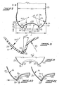
- the accommodation portion 18 further includes a stepped wall portion, indicated by the reference characters a, b, c, d, e, ( Figure 5) of decreasing biaxial molecular orientation extending around and upwardly and inwardly from the flange 17 and including at least two successive upwardly and inwardly extending stepped areas a, b, c and c, d, e.
- This stepped wall portion a, b, c, d, e terminates in a neck portion 22 which has no biaxial molecular orientation since it is utilized ( Figure 4) to secure the preform 13 within the mold M of the stretch blow-molding apparatus.
- This unique stepped wall accommodation portion 18 is designed to allow for controlled biaxial molecular orientation of the PET material in the flange 17 and to control thickness of the flange 17.
- the stepped wall a, b, c, d, e acts to collect an amount of PET during stretch blow-molding and captures an increasing amount of PET material in each of the steps a, b, c and c, d, e during the stretch blow-molding operation.
- the step c, d, e contains more PET material and has less biaxial molecular orientation than does the step a, b, c.
- This unique stepped wall also provides distinct points of demarkation between such levels of biaxial molecular orientation resulting in a high degree of biaxial molecular orientation in the flange 17 and a controlled uniform thickness in the flange 17, both of which characteristics improve the ability to attach a metal end closure by double seaming operations to the flange 17.
- prior wide-mouth container articles fabricated from an intermediate article formed by stretch blow-molding an injection-molded preform of PET utilized an accommodation portion in the form of an oblique truncated cone, as shown in the above mentioned U.S. Patents 4,496,064 and 4,576,843.
- This type of conical wall would be in the cross-sectional shape defined a line extending from reference character b to c to e (a portion of which is indicated by a dotted line in Figure 5) and would result in a gradual increase in biaxial molecular orientation of the accommodation portion from the neck at the top to the flange at the bottom.
- This variance in degree of biaxial molecular orientation through the flange and, thus, thickness in the flange does not always produce a flange of desired strength and thickness for receiving a metal end closure by double seaming operations.
- the container 10 and intermediate article 12 both include an improved base portion 16 of low biaxial molecular orientation which integrally extends from a lower end of the tubular body portion 20 and includes means, to be described below, for providing free-standing ability to the container 10 and for controlling distortion by internal pressure.
- This base portion 16 is preferably of the "champagne" type and comprises ( Figure 7) an outer peripheral wall 25 integrally extending at one end from the lower end of the tubular body portion 20 and defining a spherical segment of two bases having a predetermined radius R1 .
- the base further includes a standing ring 26 integrally extending at one end from the other end of the outer peripheral wall 25 and defining an annual toroidal segment of a predetermined radius R2 ( Figure 8).
- the base portion 16 further includes an inner standing wall 27 integrally extending at one end from the other end of the standing ring 26 and defining a frustum of a right circular cone.
- the base portion 16 includes a central dome 28 of non- biaxial molecular orientation and integrally extending from the other end of the inner standing wall 27 and defining a spherical segment of one base having a predetermined radius R3 to close the bottom of the base portion 16.
- first and second pivot or hinge means indicated schematially at P1 and P2 ( Figures 10 and 11), located at the points of accumulation of stresses on the base portion 16 as a result of internal pressure applied downwardly on the central dome 28 for allowing controlled distortion of the base portion by outward and downward movement of the first hinge means P1 and outward movement of the second hinge means P2 , as shown schematically by the arrows in Figure 10, from the position indicated in Figure 10 to that indicated in Figure 11 without significantly changing the volume of the container 10 or the free standing ability of the base portion 16.
- the hinge means P1 , P2 react to bending moments of the base and the arm connecting hinge means P1 , P2 increases in angle to the vertical as a result of the controlled distortion of the base portion 16 and urges the formation of a compound radius in the outer peripheral wall means 25 with the resultant deformation of the base portion 16, as shown in Figure 11.
- the free standing ability of the base portion 16, as provided by the standing ring 26, does not change, as may be clearly seen from a comparison of Figures 10 and 11.
- the diameter D2 which is the maximum diameter of the base 16, is preferably greater than the diameter D3 of the tubular body portion 20.
- the radius R1 of the outer peripheral wall 25 should preferably be identical to the radius R3 of the central dome 28.
- the radius R2 of the standing ring 26 is preferably between 4 to 6 percent of the radius R1 of the outer peripheral wall 25 and the radius R3 of the central dome 28.
- the sum of the surface areas of the outer peripheral wall 25, the standing ring 26, the inner standing wall 27 and the central dome 28 is preferably equal to the surface area of a perfect hemisphere having a radius equal to the radius R1 of the outer peripheral wall 25 or the radius R3 of the central dome 28.
- the ratio of the maximum diameter D2 of the base portion 16 to the inside diameter D1 of the standing ring 26 is preferably between 1.5 to 1.7.
- the height H1 of the inner standing wall 27 can be adjusted to meet the preferable surface area requirements set forth above and is preferably equal to the height H2 of the central dome 28.
- the inner standing wall 27 is at an angle ⁇ preferably of from 7 to 10 degrees to the vertical or to a longitudinal axis through the article 10.
- the central dome 28 essentially has no biaxial molecular orientation and, therefore, is of a thickness greater than the thickness of the remaining segments 25, 26, 27. As may be seen in Figure 9, the thicknesses of the outer peripheral wall 25, the standing ring 26, the inner standing wall 27 and the central dome 28 progressively increase. On a weight basis, the central dome 28, inner standing wall 27 and standing ring 26 comprise between 15 and 20 percent of the total weight of the container 10.
- this invention has provided a wide mouth container 10 and an intermediate article 12 formed by stretch blow-molding an injection-molded preform 13 of PET which is suitable for packaging tennis balls or other contents under pressure and which is characterized by an improved base construction 16 which will withstand internal pressure with controlled minimal distortion and by an improved flange construction 17 surrounding the wide mouth which provides desired strength and thickness for receiving a metal end closure 14 by double seaming operations and which is formed by a unique accommodation portion 18 in the intermediate article 12 which has a stepped wall construction.
Abstract
Description
- This invention relates to a wide mouth container and intermediate article formed by stretch blow-molding an injection-molded preform of polyethylene terephthalate (PET) suitable for packaging tennis balls or other contents under pressure and being characterized by an improved base construction which will withstand internal pressure with controlled minimal distortion and by an improved flange construction surrounding the wide mouth providing desired strength and thickness for receiving a metal end closure by double seaming operations and formed by a unique accommodation portion in the intermediate article.
- It has heretofore been established that many material characteristics of polyethylene terephthalate (PET) are improved by high biaxial molecular orientation of the plastic during blow-molding, particularly when manufacturing containers for packaging contents under pressure, such as disclosed in U.S. Patent 3,733,309. In practice, the injection-molded preform design is such that molecular orientation may take place in both axes of the container by holding the preform in a mold cavity having the volumetric configuration of the desired article, stretching the preform longitudinally within the mold and expanding the preform transversely with high pressure air into the final shape of the article and mold cavity.
- Prior container designs of biaxial molecular oriented PET, particularly for carbonated beverages, utilize a free-standing highly oriented base design which purportedly lends strength and rigidity necessary to withstand elevated pressures. The methodology for formation of freestanding pressure-resisting bases for these types of PET biaxial molecular oriented containers is described in U.S. Patent 3,598,270 for a "petaloid" type base and in U.S. Patent 4,465,199 for a "champagne" type base. However, both of these types of bases in a stretch blow-molded PET container are difficult to form, since they require high blowing pressures and/or secondary mold motions in order to stretch and blow the PET material into tight and highly defined annular spaces.
- It has also been determined, in wide-mouth stretch blow-molded PET containers, that it is desirable to have a high biaxial molecular oriented flange of desired strength and thickness extending radially outwardly from around the wide open mouth for receiving a metal end closure by conventional double seaming operations to close the stretch blow-molded PET container with pressurized contents, such as tennis balls, therein. Such a stretch blow-molded wide-mouth PET flanged container is disclosed in U.S. Patents 4,496,064 and 4,567,843 which is described as requiring complete biaxial molecular orientation for adequate performance. The method described in these patent discloses the formation of an intermediate article utilizing an oblique truncated cone type of accommodation area, including the flange portion surrounding the wide open mouth of the tubular body, which imparts a gradual increase in biaxial molecular orientation from a neck area at the top to the flange portion at the bottom of the accommodation portion. The accommodation portion is then removed by cutting through the flange to provide a container having a flange around the open mouth with biaxial molecular orientation. However, the design of the accommodation portion in the form of the oblique truncated cone makes it difficult to consistently control the degree of biaxial molecular orientation and the thickness of the flange material which often results in undesirable strength and thickness in the flange for receiving a metal end closure by double seaming operations.
- Accordingly, it is the object of this invention to overcome the above problems with prior stretch blow-molded PET wide-mouth containers and to provide a wide mouth container and intermediate article formed by stretch blow-molding an injection-molded preform of a polyethylene terephthalate (PET) suitable for packaging tennis balls or other contents under pressure and which has an improved base construction which will withstand internal pressure with controlled minimal distortion and an improved flange portion surrounding the wide mouth of desired strength and thickness for receiving a metal end closure by double seaming operations which is formed by a unique accommodation portion in the intermediate article.
- By this invention, it has been found that the above object may be accomplished by providing an intermediate article and a wide-mouth container article fabricated therefrom, wherein the intermediate article is formed by stretch blow-molding an injection-molded preform of PET, and which are constructed generally, as follows.
- The container article and the intermediate article include a tubular body portion of high biaxial molecular orientation and a base portion of low biaxial molecular orientation integrally extending from a lower end of the tubular body portion and having means incorporated therein for providing free-standing ability to the fabricated container and for controlling distortion by internal pressure.
- The base portion preferably comprises a "champagne" type base including an outer peripheral wall integrally extending at one end from the lower end of the tubular body portion and defining a spherical segment of a predetermined radius, a standing ring integrally extending at one end from the other end of the outer peripheral wall and defining an annular toroidal segment of a predetermined radius, an inner standing wall integrally extending at one end from the other end of the standing ring and defining a frustum of a right circular cone, and a central dome of essentially non-biaxial molecular orientation and integrally extending from the other end of the inner standing wall and defining a spherical segment of a predetermined radius.
- With this construction of the base portion, the juncture of the central dome and the inner standing wall and the juncture of the outer peripheral wall with the standing ring comprise first and second hinge means located at the points of accummulation of stresses on the base portion as a result of internal pressure applied downwardly on the central dome for allowing controlled minimal distortion of the base portion by outward and downward movement of the first hinge means and outward movement of the second hinge means without significantly changing the volume of the container or the free-standing ability of the base portion.
- The improved flange of high biaxial molecular orientation integrally extending around and radially outwardly from the upper open end of the tubular body portion of the wide mouth container article and having the desired strength and thickness for receiving a closure, preferably a metal end closure by double seaming operations, is provided by stretch blow-molding a unique accommodation portion in the intermediate article which extends from the upper end of the tubular body portion and includes the following. A flange of high biaxial molecular orientation extends around and radially outwardly from the upper open end of the tubular body portion and is adapted to be annularly cut to remove the remainder of the accommodation portion during fabrication of the wide-mouth container from the intermediate article. A stepped wall portion of decreasing biaxial molecular orientation extends around and upwardly and inwardly from the flange and includes at least two successive upwardly and inwardly extending step means or areas for collecting a quantity of PET during blow-molding and for increasing biaxial molecular orientation and controlling the thickness of the flange.
- While some of the objects and advantages, along with a summary, of this invention have been set forth above, other objects and advantages, along with a detailed description of a preferred embodiment, of this invention will be described below in conjunction with the following drawings, in which:
- Figure 1 is perspective view of a container constructed in accordance with this invention and containing tennis balls under pressure and having a metal end closure double seamed thereto and protective top shown exploded therefrom;
- Figure 2 is a perspective view of the intermediate article as it comes from the stretch blow-molding equipment and from which the container of Figure 1 is fabricated;
- Figure 3 is a sectional view in elevation of the injection-molded preform used to stretch blow-mold the intermediate article of Figure 2;
- Figure 4 is a schematic sectional view in elevation of a typical mold of a stretch blow-molding apparatus showing the preform of Figure 3 secured therein immediately prior to stretch blow-molding the intermediate article of Figure 2;
- Figure 5 is an elevational view of the intermediate article of Figure 2 with half of the article broken away and shown in section;
- Figure 6 is a partial perspective view of the top portion of the container article of Figure 1, without the metal end closure, after the accommodation portion of the intermediate article of Figures 2 and 3 has been cut and removed;
- Figure 7 is a sectional view in elevation of the base portion of the container article and intermediate article of Figures l, 2 and 5;
- Figure 8 is an enlarged sectional view of a portion of the base portion illustrated in Figure 7 and showing further details of radiuses, dimensions and angles of segments thereof;
- Figure 9 is a section view of a portion of the base portion of Figure 7 illustrating particularly thicknesses in the various segments of the base portion;
- Figure 10 is a partial sectional view of one side of the base portion showing schematically the hinge means in the base portion for controlled minimal distortion of the base portion under internal pressures; and
- Figure 11 is a view, like Figure 10, showing a partial section of the base portion after controlled minimal distortion has occurred.
- Referring now to the drawings, a container 10 (Figure 1) is fabricated from an intermediate article 12 (Figure 2) which is formed by stretch blow-molding an injection-molded preform 13 (Figure 3) of polyethylene terephthalate (PET). The
container 10, as illustrated in the drawings and described in connection with this preferred embodiment, is a wide-mouth container suitable for packaging tennis balls under pressure (Figure 1) by closing the wide mouth open end of thecontainer 10 using ametal end closure 14 which is covered by aprotective cap 15. Thecontainer 10 andintermediate article 12 of this invention are characterized by an improvedbase 16 construction which will withstand internal pressure with controlled minimal distortion and by an improved flange 17 construction (Figure 6) surrounding the wide mouth and providing desired strength and thickness for receiving themetal end closure 14 by conventional double seaming operations and formed by a unique accommodation portion 18 (Figures 2 and 5) in theintermediate article 12, as described more fully below. - However, it is to be understood that while the preferred embodiment of the
container 10 described herein is in the form of a wide mouth container for packaging tennis balls (Figure 1), the unique and characterizing features of the container of this invention may be utilized in other wide-mouth containers for packaging other contents under pressure. Also, the improved flange construction 17 may be utilized with wide-mouth containers which utilize other types of base constructions and the improvedbase construction 16 may be utilized in containers, other than wide-mouth containers, which package contents under pressure. - As mentioned above, the
intermediate article 12, from which the wide-mouth container 10 is fabricated, is formed by stretch blow-molding an injection-moldedpreform 13 of PET. As is well known by those with ordinary skill in the art and as more fully described in the above mentioned U.S. Patent 3,733,309, the injection-moldedpreform 13 is placed in the mold M (Figure 4) of a stretch blow-molding apparatus and is then mechanically stretched in the longitudinal direction and expanded in the transverse direction by high pressure air into the final shape of theintermediate article 12 and the shape of the cavity of the mold M which has the volumetric configuration of the desired article. As a result, biaxial molecular orientation of the PET material and resultingintermediate product 12 is obtained. However, as will be described below, this biaxial molecular orientation varies, particularly in thetop accommodation portion 18 and thebottom base portion 16 of theintermediate product 12. This stretch blow-molding operation is well understood by those with ordinary skill in the art and further explanation and discussion is not believed to be necessary for an understanding of the present invention. - The resulting stretch blow-molded PET intermediate product 12 (Figures 2 and 5) include a
tubular body portion 20 of high biaxial molecular orientation by both longitudinal and transverse stretching of the PET material during stretch blow-molding. Theintermediate article 12 further includes anaccommodation portion 18 intergrally extending from an upper end of thetubular body portion 20 and defining the flange 17, which has a high biaxial molecular orientation, extending around and radially outwardly from the upper open end of thetubular body portion 20 and which is adapted to be annularly cut at an intermediate location to remove the remainder of theaccommodation portion 18 while leaving a portion of the flange 17 intergrally connected to thebody portion 20 of the container 10 (Figure 6) for receiving theclosure 14. - The
accommodation portion 18 further includes a stepped wall portion, indicated by the reference characters a, b, c, d, e, (Figure 5) of decreasing biaxial molecular orientation extending around and upwardly and inwardly from the flange 17 and including at least two successive upwardly and inwardly extending stepped areas a, b, c and c, d, e. This stepped wall portion a, b, c, d, e terminates in aneck portion 22 which has no biaxial molecular orientation since it is utilized (Figure 4) to secure thepreform 13 within the mold M of the stretch blow-molding apparatus. This unique steppedwall accommodation portion 18 is designed to allow for controlled biaxial molecular orientation of the PET material in the flange 17 and to control thickness of the flange 17. The stepped wall a, b, c, d, e acts to collect an amount of PET during stretch blow-molding and captures an increasing amount of PET material in each of the steps a, b, c and c, d, e during the stretch blow-molding operation. Thus, the step c, d, e contains more PET material and has less biaxial molecular orientation than does the step a, b, c. This unique stepped wall also provides distinct points of demarkation between such levels of biaxial molecular orientation resulting in a high degree of biaxial molecular orientation in the flange 17 and a controlled uniform thickness in the flange 17, both of which characteristics improve the ability to attach a metal end closure by double seaming operations to the flange 17. - In contrast, prior wide-mouth container articles fabricated from an intermediate article formed by stretch blow-molding an injection-molded preform of PET utilized an accommodation portion in the form of an oblique truncated cone, as shown in the above mentioned U.S. Patents 4,496,064 and 4,576,843. This type of conical wall would be in the cross-sectional shape defined a line extending from reference character b to c to e (a portion of which is indicated by a dotted line in Figure 5) and would result in a gradual increase in biaxial molecular orientation of the accommodation portion from the neck at the top to the flange at the bottom. This variance in degree of biaxial molecular orientation through the flange and, thus, thickness in the flange does not always produce a flange of desired strength and thickness for receiving a metal end closure by double seaming operations.
- The
container 10 andintermediate article 12 both include an improvedbase portion 16 of low biaxial molecular orientation which integrally extends from a lower end of thetubular body portion 20 and includes means, to be described below, for providing free-standing ability to thecontainer 10 and for controlling distortion by internal pressure. Thisbase portion 16 is preferably of the "champagne" type and comprises (Figure 7) an outerperipheral wall 25 integrally extending at one end from the lower end of thetubular body portion 20 and defining a spherical segment of two bases having a predetermined radius R1. The base further includes a standingring 26 integrally extending at one end from the other end of the outerperipheral wall 25 and defining an annual toroidal segment of a predetermined radius R2 (Figure 8). This standingring 26 provides the free-standing ability to thecontainer 10. Thebase portion 16 further includes an inner standingwall 27 integrally extending at one end from the other end of the standingring 26 and defining a frustum of a right circular cone. Lastly, thebase portion 16 includes acentral dome 28 of non- biaxial molecular orientation and integrally extending from the other end of the inner standingwall 27 and defining a spherical segment of one base having a predetermined radius R3 to close the bottom of thebase portion 16. - The dynamics of the above described design of this
base portion 16 are such that the juncture of thecentral dome 28 and the inner standingwall 27 and the juncture of the outerperipheral wall 25 and the standingring 26 form first and second pivot or hinge means, indicated schematially at P1 and P2 (Figures 10 and 11), located at the points of accumulation of stresses on thebase portion 16 as a result of internal pressure applied downwardly on thecentral dome 28 for allowing controlled distortion of the base portion by outward and downward movement of the first hinge means P1 and outward movement of the second hinge means P2, as shown schematically by the arrows in Figure 10, from the position indicated in Figure 10 to that indicated in Figure 11 without significantly changing the volume of thecontainer 10 or the free standing ability of thebase portion 16. Thus, the hinge means P1, P2 react to bending moments of the base and the arm connecting hinge means P1, P2 increases in angle to the vertical as a result of the controlled distortion of thebase portion 16 and urges the formation of a compound radius in the outer peripheral wall means 25 with the resultant deformation of thebase portion 16, as shown in Figure 11. The free standing ability of thebase portion 16, as provided by the standingring 26, does not change, as may be clearly seen from a comparison of Figures 10 and 11. - The following dimensional relationships have been determined to be preferable to the above functioning of the
base portion 16 to provide controlled minimal distortion. The diameter D2, which is the maximum diameter of thebase 16, is preferably greater than the diameter D3 of thetubular body portion 20. The radius R1 of the outerperipheral wall 25 should preferably be identical to the radius R3 of thecentral dome 28. The radius R2 of the standingring 26 is preferably between 4 to 6 percent of the radius R1 of the outerperipheral wall 25 and the radius R3 of thecentral dome 28. - The sum of the surface areas of the outer
peripheral wall 25, the standingring 26, the inner standingwall 27 and thecentral dome 28 is preferably equal to the surface area of a perfect hemisphere having a radius equal to the radius R1 of the outerperipheral wall 25 or the radius R3 of thecentral dome 28. The ratio of the maximum diameter D2 of thebase portion 16 to the inside diameter D1 of the standingring 26 is preferably between 1.5 to 1.7. The height H1 of the inner standingwall 27 can be adjusted to meet the preferable surface area requirements set forth above and is preferably equal to the height H2 of thecentral dome 28. Theinner standing wall 27 is at an angle ⌀ preferably of from 7 to 10 degrees to the vertical or to a longitudinal axis through thearticle 10. - As mentioned above, the
central dome 28 essentially has no biaxial molecular orientation and, therefore, is of a thickness greater than the thickness of the remainingsegments peripheral wall 25, the standingring 26, the inner standingwall 27 and thecentral dome 28 progressively increase. On a weight basis, thecentral dome 28, inner standingwall 27 and standingring 26 comprise between 15 and 20 percent of the total weight of thecontainer 10. - Thus, this invention has provided a
wide mouth container 10 and anintermediate article 12 formed by stretch blow-molding an injection-moldedpreform 13 of PET which is suitable for packaging tennis balls or other contents under pressure and which is characterized by animproved base construction 16 which will withstand internal pressure with controlled minimal distortion and by an improved flange construction 17 surrounding the wide mouth which provides desired strength and thickness for receiving ametal end closure 14 by double seaming operations and which is formed by aunique accommodation portion 18 in theintermediate article 12 which has a stepped wall construction. - In the drawings and specification there have been set forth a preferred embodiment of this invention, and although specific terms are employed, they are used in a generic and descriptive sense only and not for purposes of limitation, the scope of the invention is defined in the following claims.
Claims (16)
Applications Claiming Priority (2)
| Application Number | Priority Date | Filing Date | Title |
|---|---|---|---|
| US07/129,706 US4894268A (en) | 1987-12-07 | 1987-12-07 | Stretch blow-molded polyethylene terephthalate wide mouth container and intermediate article |
| US129706 | 1987-12-07 |
Related Child Applications (1)
| Application Number | Title | Priority Date | Filing Date |
|---|---|---|---|
| EP92115228.6 Division-Into | 1988-11-25 |
Publications (3)
| Publication Number | Publication Date |
|---|---|
| EP0320151A2 true EP0320151A2 (en) | 1989-06-14 |
| EP0320151A3 EP0320151A3 (en) | 1990-01-17 |
| EP0320151B1 EP0320151B1 (en) | 1994-04-20 |
Family
ID=22441205
Family Applications (2)
| Application Number | Title | Priority Date | Filing Date |
|---|---|---|---|
| EP92115228A Withdrawn EP0523749A1 (en) | 1987-12-07 | 1988-11-25 | Stretch blow-molded polyethylene terephthalate wide mouth container and intermediate article |
| EP88311164A Expired - Lifetime EP0320151B1 (en) | 1987-12-07 | 1988-11-25 | PET intermediate article |
Family Applications Before (1)
| Application Number | Title | Priority Date | Filing Date |
|---|---|---|---|
| EP92115228A Withdrawn EP0523749A1 (en) | 1987-12-07 | 1988-11-25 | Stretch blow-molded polyethylene terephthalate wide mouth container and intermediate article |
Country Status (15)
| Country | Link |
|---|---|
| US (1) | US4894268A (en) |
| EP (2) | EP0523749A1 (en) |
| JP (1) | JPH0622859B2 (en) |
| KR (1) | KR950007146B1 (en) |
| CN (1) | CN1017131B (en) |
| AT (1) | ATE104628T1 (en) |
| AU (1) | AU606557B2 (en) |
| BR (1) | BR8806439A (en) |
| CA (1) | CA1314826C (en) |
| DE (2) | DE3889206T2 (en) |
| ES (1) | ES2010160T3 (en) |
| GR (1) | GR890300170T1 (en) |
| IN (1) | IN171136B (en) |
| MX (1) | MX165668B (en) |
| ZA (1) | ZA888901B (en) |
Cited By (6)
| Publication number | Priority date | Publication date | Assignee | Title |
|---|---|---|---|---|
| WO1995006593A1 (en) * | 1993-09-02 | 1995-03-09 | Rhodia-Ster Fipack S/A. | A plastic bottle for hot filling |
| CN1041613C (en) * | 1992-05-13 | 1999-01-13 | 柳崇明 | Production method for plastic body of pop-top can with metal top and equipment thereof |
| EP0943420A1 (en) * | 1998-03-17 | 1999-09-22 | Schütz-Werke GmbH & Co. KG. | Method for manufacturing plastic bunghole barrels and lid covered barrels and method for reconditioning of bunghole barrels |
| EP0994034A2 (en) * | 1998-10-14 | 2000-04-19 | Pechiney Plastic Packaging, Inc. | Plastic container having base with annular wall and method of making the same |
| EP0989072A3 (en) * | 1998-09-25 | 2003-05-28 | Sumitomo Rubber Industries Ltd. | Wide-mouth container made of synthetic resin and method of manufacturing pressure resistant wide-mouth container |
| WO2008059256A2 (en) * | 2006-11-15 | 2008-05-22 | The Plastic Can Company Limited | Method and apparatus for making a container with a pressure accomodating base |
Families Citing this family (31)
| Publication number | Priority date | Publication date | Assignee | Title |
|---|---|---|---|---|
| US4942008A (en) * | 1985-07-10 | 1990-07-17 | Cahill John W | Process for molding a multiple layer structure |
| CN1022900C (en) * | 1989-10-07 | 1993-12-01 | 株式会社吉野工业所 | Elongation moulding pot made from synthetic resin |
| US5137179A (en) * | 1990-02-15 | 1992-08-11 | Hans Stoffel | Containers and methods for preparing and manufacturing the same |
| US5251770A (en) * | 1992-05-06 | 1993-10-12 | Broadway Companies, Inc. | Container and pressure sealing closure combination |
| US6228317B1 (en) | 1998-07-30 | 2001-05-08 | Graham Packaging Company, L.P. | Method of making wide mouth blow molded container |
| JP2000128140A (en) * | 1998-10-20 | 2000-05-09 | Aoki Technical Laboratory Inc | Polyester resin-made heat-resistant packaging container |
| RU2164887C1 (en) * | 2000-03-24 | 2001-04-10 | Общество с ограниченной ответственностью "Водолей 2001" | Jar for food and method of its making |
| EP1927460A2 (en) * | 2001-07-17 | 2008-06-04 | Frontier Inc. | Biaxial stretch blow molding apparatus for wide-mouthed containers |
| CN2570208Y (en) * | 2001-09-03 | 2003-09-03 | 珠海中富聚酯啤酒瓶有限公司 | Polyester beer bottle |
| US6769561B2 (en) * | 2001-12-21 | 2004-08-03 | Ball Corporation | Plastic bottle with champagne base |
| US6814923B2 (en) * | 2001-12-27 | 2004-11-09 | Graham Packaging Company, L.P. | Preform, intermediate article and method for manufacturing a blown finish container |
| US7153466B2 (en) * | 2002-08-20 | 2006-12-26 | Sonoco Development, Inc. | Method and apparatus for blow-molding an article having a solid radially outwardly projecting flange |
| US20040035874A1 (en) * | 2002-08-20 | 2004-02-26 | Sonoco Development, Inc. | Extrusion blow molding methods and articles made thereby |
| US6896147B2 (en) * | 2003-02-14 | 2005-05-24 | Graham Packaging Company, L.P. | Base structure for a container |
| US7531125B2 (en) * | 2003-08-25 | 2009-05-12 | Ring Container Technologies | Blow molded wide mouth pet container and method of manufacture |
| US6971530B2 (en) * | 2003-12-12 | 2005-12-06 | Plastipak Packaging, Inc. | Plastic container having stepped neck finish |
| US7481961B2 (en) * | 2004-04-01 | 2009-01-27 | Graham Packaging Pet Technologies, Inc. | Multilayer container trimming |
| CN1310804C (en) * | 2004-04-13 | 2007-04-18 | 珠海中富实业股份有限公司 | Wide mouth container bottle, method and device for producing wide mouth container bottle |
| TWI304373B (en) | 2004-05-14 | 2008-12-21 | Mitsui Chemicals Inc | Polyester resin bottle |
| US7416089B2 (en) * | 2004-12-06 | 2008-08-26 | Constar International Inc. | Hot-fill type plastic container with reinforced heel |
| US7780025B2 (en) * | 2005-11-14 | 2010-08-24 | Graham Packaging Company, L.P. | Plastic container base structure and method for hot filling a plastic container |
| EP1993916A1 (en) * | 2006-03-13 | 2008-11-26 | The Iams Company | Container for pet products |
| DE102007002131A1 (en) * | 2006-09-01 | 2008-03-06 | Strecktech Ag | Method and device for producing tube-like bodies |
| DE102007002132A1 (en) * | 2006-09-01 | 2008-03-06 | Strecktech Ag | Method and device for producing tube-like bodies |
| US20080116162A1 (en) * | 2006-11-17 | 2008-05-22 | Penny Michael E | Container with tamper evident band |
| US7931464B2 (en) | 2008-04-09 | 2011-04-26 | Ball Corporation | Apparatus for extrusion-blow molding a bottle for assembly with metal can end |
| US8047388B2 (en) * | 2008-12-08 | 2011-11-01 | Graham Packaging Company, L.P. | Plastic container having a deep-inset base |
| US20110049083A1 (en) * | 2009-09-01 | 2011-03-03 | Scott Anthony J | Base for pressurized bottles |
| GB201008520D0 (en) | 2010-05-21 | 2010-07-07 | Brittpac Ltd | Containers |
| FR3012115B1 (en) * | 2013-10-23 | 2015-12-11 | Sidel Participations | CONTAINER WITH AN EVOLUTIVE SECTION BETWEEN A SQUARE CONTOUR AND A RECTANGULAR CONTOUR |
| CH715202A1 (en) * | 2018-07-25 | 2020-01-31 | Alpla Werke Alwin Lehner Gmbh & Co Kg | Stretch blow molding process for the production of a plastic container and plastic container produced in a stretch blow molding process. |
Citations (4)
| Publication number | Priority date | Publication date | Assignee | Title |
|---|---|---|---|---|
| US4465199A (en) * | 1981-06-22 | 1984-08-14 | Katashi Aoki | Pressure resisting plastic bottle |
| EP0140719A1 (en) * | 1983-07-22 | 1985-05-08 | Nissei Asb Machine Co., Ltd. | Method for manufacturing synthetic resin can bodies |
| DE8534061U1 (en) * | 1985-12-04 | 1986-01-16 | Chang, Chin-Yen, Taichung, Taiwan | Container for holding tennis balls |
| US4576843A (en) * | 1981-11-23 | 1986-03-18 | The Continental Group, Inc. | Blow molded containers and method of forming the same |
Family Cites Families (7)
| Publication number | Priority date | Publication date | Assignee | Title |
|---|---|---|---|---|
| JPS55163137A (en) * | 1979-05-31 | 1980-12-18 | Yoshizaki Kozo | Plasticcmade pressure container and making method thereof |
| JPS56164911U (en) * | 1980-05-06 | 1981-12-07 | ||
| SE428775B (en) * | 1981-11-26 | 1983-07-25 | Plm Ab | CONTAINERS AND SETS AND APPARATUS FOR MAKING A SUGAR |
| JPS598221A (en) * | 1982-07-05 | 1984-01-17 | 株式会社東芝 | Opening and closing operation device |
| US4502607A (en) * | 1983-06-21 | 1985-03-05 | Continental Plastic Containers, Inc. | Bulge resistant bottle bottom |
| JPS6045146A (en) * | 1983-08-23 | 1985-03-11 | 東洋紡績株式会社 | Polyester vessel with metallic cover |
| JPS6229377U (en) * | 1985-08-06 | 1987-02-21 |
-
1987
- 1987-12-07 US US07/129,706 patent/US4894268A/en not_active Expired - Fee Related
-
1988
- 1988-11-23 CA CA000583935A patent/CA1314826C/en not_active Expired - Fee Related
- 1988-11-25 AT AT8888311164T patent/ATE104628T1/en not_active IP Right Cessation
- 1988-11-25 IN IN972/CAL/88A patent/IN171136B/en unknown
- 1988-11-25 EP EP92115228A patent/EP0523749A1/en not_active Withdrawn
- 1988-11-25 DE DE3889206T patent/DE3889206T2/en not_active Expired - Fee Related
- 1988-11-25 EP EP88311164A patent/EP0320151B1/en not_active Expired - Lifetime
- 1988-11-25 DE DE198888311164T patent/DE320151T1/en active Pending
- 1988-11-25 ES ES88311164T patent/ES2010160T3/en not_active Expired - Lifetime
- 1988-11-28 ZA ZA888901A patent/ZA888901B/en unknown
- 1988-12-06 AU AU26588/88A patent/AU606557B2/en not_active Ceased
- 1988-12-06 JP JP30705588A patent/JPH0622859B2/en not_active Expired - Lifetime
- 1988-12-07 BR BR888806439A patent/BR8806439A/en not_active IP Right Cessation
- 1988-12-07 CN CN88108377A patent/CN1017131B/en not_active Expired
- 1988-12-07 KR KR1019880016266A patent/KR950007146B1/en not_active IP Right Cessation
- 1988-12-07 MX MX014073A patent/MX165668B/en unknown
-
1990
- 1990-12-31 GR GR89300170T patent/GR890300170T1/en unknown
Patent Citations (4)
| Publication number | Priority date | Publication date | Assignee | Title |
|---|---|---|---|---|
| US4465199A (en) * | 1981-06-22 | 1984-08-14 | Katashi Aoki | Pressure resisting plastic bottle |
| US4576843A (en) * | 1981-11-23 | 1986-03-18 | The Continental Group, Inc. | Blow molded containers and method of forming the same |
| EP0140719A1 (en) * | 1983-07-22 | 1985-05-08 | Nissei Asb Machine Co., Ltd. | Method for manufacturing synthetic resin can bodies |
| DE8534061U1 (en) * | 1985-12-04 | 1986-01-16 | Chang, Chin-Yen, Taichung, Taiwan | Container for holding tennis balls |
Cited By (10)
| Publication number | Priority date | Publication date | Assignee | Title |
|---|---|---|---|---|
| CN1041613C (en) * | 1992-05-13 | 1999-01-13 | 柳崇明 | Production method for plastic body of pop-top can with metal top and equipment thereof |
| WO1995006593A1 (en) * | 1993-09-02 | 1995-03-09 | Rhodia-Ster Fipack S/A. | A plastic bottle for hot filling |
| US5704504A (en) * | 1993-09-02 | 1998-01-06 | Rhodia-Ster Fipack S.A. | Plastic bottle for hot filling |
| EP0943420A1 (en) * | 1998-03-17 | 1999-09-22 | Schütz-Werke GmbH & Co. KG. | Method for manufacturing plastic bunghole barrels and lid covered barrels and method for reconditioning of bunghole barrels |
| EP0989072A3 (en) * | 1998-09-25 | 2003-05-28 | Sumitomo Rubber Industries Ltd. | Wide-mouth container made of synthetic resin and method of manufacturing pressure resistant wide-mouth container |
| EP0994034A2 (en) * | 1998-10-14 | 2000-04-19 | Pechiney Plastic Packaging, Inc. | Plastic container having base with annular wall and method of making the same |
| EP0994034A3 (en) * | 1998-10-14 | 2000-06-14 | Pechiney Plastic Packaging, Inc. | Plastic container having base with annular wall and method of making the same |
| US6176382B1 (en) | 1998-10-14 | 2001-01-23 | American National Can Company | Plastic container having base with annular wall and method of making the same |
| WO2008059256A2 (en) * | 2006-11-15 | 2008-05-22 | The Plastic Can Company Limited | Method and apparatus for making a container with a pressure accomodating base |
| WO2008059256A3 (en) * | 2006-11-15 | 2008-08-14 | Plastic Can Company Ltd | Method and apparatus for making a container with a pressure accomodating base |
Also Published As
| Publication number | Publication date |
|---|---|
| CN1035080A (en) | 1989-08-30 |
| ES2010160T3 (en) | 1994-07-01 |
| EP0320151B1 (en) | 1994-04-20 |
| US4894268A (en) | 1990-01-16 |
| EP0523749A1 (en) | 1993-01-20 |
| MX165668B (en) | 1992-11-27 |
| ZA888901B (en) | 1989-08-30 |
| ATE104628T1 (en) | 1994-05-15 |
| DE320151T1 (en) | 1990-02-08 |
| DE3889206T2 (en) | 1994-09-22 |
| IN171136B (en) | 1992-08-01 |
| CN1017131B (en) | 1992-06-24 |
| EP0320151A3 (en) | 1990-01-17 |
| KR890009730A (en) | 1989-08-03 |
| BR8806439A (en) | 1989-08-22 |
| JPH0622859B2 (en) | 1994-03-30 |
| GR890300170T1 (en) | 1990-12-31 |
| AU606557B2 (en) | 1991-02-07 |
| JPH01221220A (en) | 1989-09-04 |
| AU2658888A (en) | 1989-06-08 |
| CA1314826C (en) | 1993-03-23 |
| KR950007146B1 (en) | 1995-06-30 |
| ES2010160A4 (en) | 1989-11-01 |
| DE3889206D1 (en) | 1994-05-26 |
Similar Documents
| Publication | Publication Date | Title |
|---|---|---|
| EP0320151B1 (en) | PET intermediate article | |
| EP0277557B1 (en) | Blow molded plastic container | |
| CA1157787A (en) | Self-supporting plastic container for liquids and method of making same | |
| CA1203759A (en) | Blow molded container and method of forming the same | |
| US3881621A (en) | Plastic container with noneverting bottom | |
| CA2286820C (en) | Plastic blow molded water bottle | |
| US4403706A (en) | Plastic container with hollow internal rib reinforced bottom and method of forming the same | |
| US5024339A (en) | Plastics bottle | |
| US4525401A (en) | Plastic container with internal rib reinforced bottom | |
| US6666001B2 (en) | Plastic container having an outwardly bulged portion | |
| AU706912B2 (en) | Plastic blow molded container and method for making the container | |
| CA2003113A1 (en) | Plastics bottles and similar containers | |
| US4796766A (en) | Plastic container and method of forming same | |
| US4969563A (en) | Self-stabilizing base for pressurized bottle | |
| CA1153324A (en) | Plastic container with internal rib reinforced bottom and method of forming same | |
| US4950514A (en) | Plastic preform for forming blow molded plastic bodies | |
| JPH0624759B2 (en) | Method for manufacturing blow molded plastic container | |
| US20070045221A1 (en) | Plastic container having a ring-shaped reinforcement and method of making same | |
| US4955492A (en) | Plastic bottle with reinforcing ring encircling the bottle base | |
| US5038947A (en) | Self-stabilizing base for pressurized bottle | |
| EP0091275A2 (en) | Improved plastic container and method of forming same | |
| JPH091639A (en) | Stretch blow molding preform and molding method using the same | |
| CA1153325A (en) | Plastic container with internal rib reinforced bottom and method of making same | |
| MXPA99009834A (en) | Plastic bottle for water, molded by sopl |
Legal Events
| Date | Code | Title | Description |
|---|---|---|---|
| PUAI | Public reference made under article 153(3) epc to a published international application that has entered the european phase |
Free format text: ORIGINAL CODE: 0009012 |
|
| AK | Designated contracting states |
Kind code of ref document: A2 Designated state(s): AT BE CH DE ES FR GB GR IT LI LU NL SE |
|
| ITCL | It: translation for ep claims filed |
Representative=s name: JACOBACCI CASETTA & PERANI S.P.A. |
|
| TCAT | At: translation of patent claims filed | ||
| EL | Fr: translation of claims filed | ||
| PUAL | Search report despatched |
Free format text: ORIGINAL CODE: 0009013 |
|
| AK | Designated contracting states |
Kind code of ref document: A3 Designated state(s): AT BE CH DE ES FR GB GR IT LI LU NL SE |
|
| DET | De: translation of patent claims | ||
| 17P | Request for examination filed |
Effective date: 19900126 |
|
| 17Q | First examination report despatched |
Effective date: 19920515 |
|
| GRAA | (expected) grant |
Free format text: ORIGINAL CODE: 0009210 |
|
| AK | Designated contracting states |
Kind code of ref document: B1 Designated state(s): AT BE CH DE ES FR GB GR IT LI LU NL SE |
|
| REF | Corresponds to: |
Ref document number: 104628 Country of ref document: AT Date of ref document: 19940515 Kind code of ref document: T |
|
| XX | Miscellaneous (additional remarks) |
Free format text: TEILANMELDUNG 92115228.6 EINGEREICHT AM 25/11/88. |
|
| REF | Corresponds to: |
Ref document number: 3889206 Country of ref document: DE Date of ref document: 19940526 |
|
| REG | Reference to a national code |
Ref country code: ES Ref legal event code: FG2A Ref document number: 2010160 Country of ref document: ES Kind code of ref document: T3 |
|
| ITF | It: translation for a ep patent filed |
Owner name: JACOBACCI CASETTA & PERANI S.P.A. |
|
| ET | Fr: translation filed | ||
| REG | Reference to a national code |
Ref country code: GR Ref legal event code: FG4A Free format text: 3012595 |
|
| EAL | Se: european patent in force in sweden |
Ref document number: 88311164.3 |
|
| PLBE | No opposition filed within time limit |
Free format text: ORIGINAL CODE: 0009261 |
|
| STAA | Information on the status of an ep patent application or granted ep patent |
Free format text: STATUS: NO OPPOSITION FILED WITHIN TIME LIMIT |
|
| 26N | No opposition filed | ||
| PGFP | Annual fee paid to national office [announced via postgrant information from national office to epo] |
Ref country code: SE Payment date: 19981117 Year of fee payment: 11 Ref country code: GB Payment date: 19981117 Year of fee payment: 11 Ref country code: CH Payment date: 19981117 Year of fee payment: 11 Ref country code: AT Payment date: 19981117 Year of fee payment: 11 |
|
| PGFP | Annual fee paid to national office [announced via postgrant information from national office to epo] |
Ref country code: ES Payment date: 19981125 Year of fee payment: 11 |
|
| PGFP | Annual fee paid to national office [announced via postgrant information from national office to epo] |
Ref country code: NL Payment date: 19981130 Year of fee payment: 11 Ref country code: GR Payment date: 19981130 Year of fee payment: 11 Ref country code: FR Payment date: 19981130 Year of fee payment: 11 |
|
| PGFP | Annual fee paid to national office [announced via postgrant information from national office to epo] |
Ref country code: DE Payment date: 19981202 Year of fee payment: 11 |
|
| PGFP | Annual fee paid to national office [announced via postgrant information from national office to epo] |
Ref country code: LU Payment date: 19981210 Year of fee payment: 11 |
|
| PGFP | Annual fee paid to national office [announced via postgrant information from national office to epo] |
Ref country code: BE Payment date: 19981215 Year of fee payment: 11 |
|
| PG25 | Lapsed in a contracting state [announced via postgrant information from national office to epo] |
Ref country code: LU Free format text: LAPSE BECAUSE OF NON-PAYMENT OF DUE FEES Effective date: 19991125 Ref country code: GB Free format text: LAPSE BECAUSE OF NON-PAYMENT OF DUE FEES Effective date: 19991125 Ref country code: AT Free format text: LAPSE BECAUSE OF NON-PAYMENT OF DUE FEES Effective date: 19991125 |
|
| PG25 | Lapsed in a contracting state [announced via postgrant information from national office to epo] |
Ref country code: SE Free format text: LAPSE BECAUSE OF NON-PAYMENT OF DUE FEES Effective date: 19991126 Ref country code: ES Free format text: LAPSE BECAUSE OF NON-PAYMENT OF DUE FEES Effective date: 19991126 |
|
| PG25 | Lapsed in a contracting state [announced via postgrant information from national office to epo] |
Ref country code: LI Free format text: LAPSE BECAUSE OF NON-PAYMENT OF DUE FEES Effective date: 19991130 Ref country code: CH Free format text: LAPSE BECAUSE OF NON-PAYMENT OF DUE FEES Effective date: 19991130 Ref country code: BE Free format text: LAPSE BECAUSE OF NON-PAYMENT OF DUE FEES Effective date: 19991130 |
|
| BERE | Be: lapsed |
Owner name: SONOCO PRODUCTS CY Effective date: 19991130 |
|
| PG25 | Lapsed in a contracting state [announced via postgrant information from national office to epo] |
Ref country code: NL Free format text: LAPSE BECAUSE OF NON-PAYMENT OF DUE FEES Effective date: 20000601 |
|
| PG25 | Lapsed in a contracting state [announced via postgrant information from national office to epo] |
Ref country code: GR Free format text: LAPSE BECAUSE OF NON-PAYMENT OF DUE FEES Effective date: 20000606 |
|
| GBPC | Gb: european patent ceased through non-payment of renewal fee |
Effective date: 19991125 |
|
| REG | Reference to a national code |
Ref country code: CH Ref legal event code: PL |
|
| EUG | Se: european patent has lapsed |
Ref document number: 88311164.3 |
|
| PG25 | Lapsed in a contracting state [announced via postgrant information from national office to epo] |
Ref country code: FR Free format text: LAPSE BECAUSE OF NON-PAYMENT OF DUE FEES Effective date: 20000731 |
|
| NLV4 | Nl: lapsed or anulled due to non-payment of the annual fee |
Effective date: 20000601 |
|
| PG25 | Lapsed in a contracting state [announced via postgrant information from national office to epo] |
Ref country code: DE Free format text: LAPSE BECAUSE OF NON-PAYMENT OF DUE FEES Effective date: 20000901 |
|
| REG | Reference to a national code |
Ref country code: FR Ref legal event code: ST |
|
| REG | Reference to a national code |
Ref country code: ES Ref legal event code: FD2A Effective date: 20001214 |
|
| PG25 | Lapsed in a contracting state [announced via postgrant information from national office to epo] |
Ref country code: IT Free format text: LAPSE BECAUSE OF NON-PAYMENT OF DUE FEES Effective date: 20051125 |