EP3637809A1 - Procédé d'indication de validité d'informations de système, dispositif de réseau et dispositif terminal - Google Patents
Procédé d'indication de validité d'informations de système, dispositif de réseau et dispositif terminal Download PDFInfo
- Publication number
- EP3637809A1 EP3637809A1 EP17927576.3A EP17927576A EP3637809A1 EP 3637809 A1 EP3637809 A1 EP 3637809A1 EP 17927576 A EP17927576 A EP 17927576A EP 3637809 A1 EP3637809 A1 EP 3637809A1
- Authority
- EP
- European Patent Office
- Prior art keywords
- sib
- validity indication
- sibs
- validity
- terminal device
- Prior art date
- Legal status (The legal status is an assumption and is not a legal conclusion. Google has not performed a legal analysis and makes no representation as to the accuracy of the status listed.)
- Withdrawn
Links
Images


Classifications
-
- H—ELECTRICITY
- H04—ELECTRIC COMMUNICATION TECHNIQUE
- H04W—WIRELESS COMMUNICATION NETWORKS
- H04W48/00—Access restriction; Network selection; Access point selection
- H04W48/08—Access restriction or access information delivery, e.g. discovery data delivery
- H04W48/12—Access restriction or access information delivery, e.g. discovery data delivery using downlink control channel
-
- H—ELECTRICITY
- H04—ELECTRIC COMMUNICATION TECHNIQUE
- H04W—WIRELESS COMMUNICATION NETWORKS
- H04W8/00—Network data management
- H04W8/18—Processing of user or subscriber data, e.g. subscribed services, user preferences or user profiles; Transfer of user or subscriber data
-
- H—ELECTRICITY
- H04—ELECTRIC COMMUNICATION TECHNIQUE
- H04L—TRANSMISSION OF DIGITAL INFORMATION, e.g. TELEGRAPHIC COMMUNICATION
- H04L5/00—Arrangements affording multiple use of the transmission path
- H04L5/003—Arrangements for allocating sub-channels of the transmission path
- H04L5/0044—Arrangements for allocating sub-channels of the transmission path allocation of payload
-
- H—ELECTRICITY
- H04—ELECTRIC COMMUNICATION TECHNIQUE
- H04W—WIRELESS COMMUNICATION NETWORKS
- H04W4/00—Services specially adapted for wireless communication networks; Facilities therefor
- H04W4/06—Selective distribution of broadcast services, e.g. multimedia broadcast multicast service [MBMS]; Services to user groups; One-way selective calling services
-
- H—ELECTRICITY
- H04—ELECTRIC COMMUNICATION TECHNIQUE
- H04W—WIRELESS COMMUNICATION NETWORKS
- H04W56/00—Synchronisation arrangements
- H04W56/001—Synchronization between nodes
-
- H—ELECTRICITY
- H04—ELECTRIC COMMUNICATION TECHNIQUE
- H04W—WIRELESS COMMUNICATION NETWORKS
- H04W72/00—Local resource management
- H04W72/04—Wireless resource allocation
- H04W72/044—Wireless resource allocation based on the type of the allocated resource
-
- H—ELECTRICITY
- H04—ELECTRIC COMMUNICATION TECHNIQUE
- H04W—WIRELESS COMMUNICATION NETWORKS
- H04W8/00—Network data management
Definitions
- the disclosure relates to the technical field of information processing, and particularly to a method for indicating validity of System Information (SI), a network device, a terminal device and a computer storage medium.
- SI System Information
- SI includes Minimum SI (MSI) and other SI.
- MSI is included in a Synchronization Signal (SS) block through default broadcast, and each beam may include a piece of MSI.
- SS Synchronization Signal
- RRC Radio Resource Control
- the other SI is transmitted by on-demand broadcast or unicast, namely transmitted through dedicated Radio Resource Control (RRC) signaling.
- RRC Radio Resource Control
- the other SI may include multiple independent SI Blocks (SIBs), each independent SIB may be or may not be broadcast, and a value of each SIB may change independently.
- a terminal monitors information of a Master Information Block (MIB) and SIB 1 on a specific time-frequency resource after acquiring a downlink SS from a Primary Synchronization Signal (PSS) and a Secondary Synchronization Signal (SSS), and then acquires scheduling information of other SIBs from the SIB 1.
- MIB Master Information Block
- PSS Primary Synchronization Signal
- SSS Secondary Synchronization Signal
- an existing LTE SI mechanism cannot be adapted to a mechanism which enables an SIB to be acquired flexibly on demand by an NR system.
- embodiments of the disclosure provide methods for indicating validity of SI, a network device, a terminal device and a computer storage medium.
- An embodiment of the disclosure provides a method for indicating validity of SI, which may be applied to a network device and include the following operations:
- An embodiment of the disclosure provides a method for indicating validity of SI, which may be applied to a terminal device and include the following operations:
- An embodiment of the disclosure provides a network device, which may include a first processing unit and a communication unit.
- the first processing unit may be configured to configure a validity indication for at least one SIB.
- the communication unit may be configured to transmit the validity indication for an SIB to be reacquired to a terminal device.
- An embodiment of the disclosure provides a terminal device, which may include a detection unit and a second processing unit.
- the detection unit may be configured to detect a validity indication, transmitted by a network side, for an SIB to be reacquired, the validity indication being for at least one SIB.
- the second processing unit may be configured to reacquire the SIB based on the validity indication.
- An embodiment of the disclosure provides a network device, which may include a processor and a memory configured to store a computer program capable of running in the processor.
- the processor may be configured to run the computer program to execute the steps of the above-mentioned method.
- An embodiment of the disclosure provides a terminal device, which may include a processor and a memory configured to store a computer program capable of running in the processor.
- the processor may be configured to run the computer program to execute the steps of the above-mentioned method.
- An embodiment of the disclosure provides a computer storage medium, which may store a computer-executable instruction, the computer-executable instruction being executed to implement the steps of the above-mentioned methods.
- a validity indication may be configured for at least one SIB, so that a system may support a scenario that multiple SIBs may be indicated by a same validity indication and may further be adapted to a system mechanism of flexibly acquiring an SIB on demand.
- the embodiment of the disclosure provides a method for indicating validity of SI, which is applied to a network device and, as shown in FIG. 1 , includes the following operations.
- a validity indication for at least one SIB is configured.
- the validity indication for an SIB to be reacquired is transmitted to a terminal device.
- the network device in the embodiment may be a base station on a network side, which for example, may be an Evolved Node B (eNB) or a gNB.
- the base station may configure a validity indication is for one or more SIBs, so that a terminal may detect a change in the validity indication to determine whether an SIB is needed to be reacquired or not.
- SIBs may be located in the same or different SI messages.
- configuring the validity indication for the at least one SIB may refer to configuring one validity indication for one or more SIBs respectively, that is, the same validity indication may correspond to at least one SIB. For example, if there are totally eight SIBs, each SIB may be provided with one validity indication, or each of seven or fewer SIBs therein may be provided with one validity indication, and moreover, a same validity indication may be used for part of the SIBs.
- the validity indication may be a finite set of positive integers, for example, 1-16 or 1-32.
- a change in a value of the validity indication means that an SIB is not valid anymore and is required to be reacquired by the terminal. That is, upon when a certain SIB is not valid anymore, the network side can make the terminal device learn about whether an SIB is needed to be reacquired or not by transmitting a validity indication to the terminal device through a system message.
- the embodiment may further include that validity indications configured for all SIBs are transmitted to the terminal device.
- the terminal device and the network side can have the same validity indications for the corresponding SIBs and thus learn about whether the corresponding SIBs have gotten invalid or not only by reading the validity indications.
- the position of a validity indication is described in the embodiment as follows: the validity indication for an SIB to be reacquired is placed in MSI in a centralized or distributed manner and transmitted to the terminal device to instruct the terminal device to reacquire the SIB.
- multiple SI validity indications may be placed in the MSI in a centralized manner (the MSI includes an MIB and Remaining MSI (RMSI)).
- the MSI includes an MIB and Remaining MSI (RMSI)).
- the validity indication for the SIB to be reacquired may be placed in SIB 1 in the MSI in the centralized manner.
- RMSI may include SIB 1 or SIB 2, and the validity indication may be in the SIB 1.
- the validity indication may also be placed in different SIBs in a distributed manner. In an example, all the validity indications of multiple SIBs may be placed in the SIB 1, and thus User Equipment (UE) may learn whether an SIB is needed to be reacquired or not upon acquiring the MSI.
- UE User Equipment
- the validity indication for the at least one SIB may be configured in the following manners.
- Manner 1 a validity indication is configured for each of at least one SIB other than the SIB 1.
- a system value tag is independently defined for an SIB in a single piece of other SI.
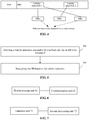
- This method is flexible, but a larger capacity may be required for the RMSI/SIB 1. For example, if a system value tag needs five bits, then eight pieces of other SI may need 40 bits. An NR system has a larger capacity than an LTE system, therefore, 40 bits may be acceptable in the SIB 1. However, if there are more SIBs of other SI, more bits may be occupied. Therefore, other solutions need to be considered. Referring to FIG. 2 , a scenario that one validity indication corresponds to one SIB is shown in the figure.
- Manner 2 at least part of SIBs are selected from the at least one SIB other than the SIB 1, and a same validity indication is configured for the at least part of SIBs.
- the operation that the at least part of SIBs are selected from the at least one SIB other than the SIB 1 may include that:
- Validity indications may be partially shared. If the use of an independent validity indication for a single SIB may excessively increase the capacity of the SIB 1, flexible partial sharing may be adopted. Partial sharing may be implemented based on whether multiple SIBs may be placed in the same SI message or not, namely SIBs in the same SI message may share the same validity indication. For example, referring to FIG. 3 , both SIB x and SIB y belongs to SI message 1 and SIB z belongs to SI message 2. In such a case, validity indication 1 may be configured for both the SIB x and the SIB y, and validity indication 2 is allocated to the SIB z.
- SI relativity may also be adopted for partial sharing.
- a shared validity indication may be used, for example, the validity indication 1 shown in the figure; and the validity indication 2 may be used for the SIB y.
- different SIBs related to Multimedia Broadcast Multicast Service (MBMS) and SIBs related to Device-to-Device (D2D) discovery and D2D communication may share the same validity indications. Accordingly, sharing a validity indication may result in that the validity indication may change with change of any SIB.
- MBMS Multimedia Broadcast Multicast Multicast Service
- D2D Device-to-Device
- a validity indication may be configured for at least one SIB with the above solution, so that a system may support that multiple SIBs may be indicated by the same validity indication and may further be adapted to a system mechanism of flexibly acquiring an SIB on demand.
- the embodiment of the disclosure provides a method for indicating validity of SI, which is applied to a terminal device and, as shown in FIG. 5 , includes the following operations.
- a validity indication transmitted by a network side, for an SIB to be reacquired is detected, the validity indication being for at least one SIB.
- the SIB is reacquired based on the validity indication.
- the network device in the embodiment may be a base station on a network side, which for example, may be an eNB or a gNB.
- the base station may configure a validity indication for one or more SIBs, so that a terminal may determine whether an SIB is required to be reacquired or not by detecting a change in the validity indication.
- SIBs may be in the same or different SI messages.
- configuring the validity indication for the at least one SIB may refer to configuring one validity indication respectively for one or more SIBs, that is, a same validity indication may correspond to at least one SIB. If there are totally eight SIBs, one piece of validity indication information may be set for each SIB respectively; or one validity indication may be set for each of seven or fewer SIBs therein respectively, and moreover, a same validity indication may be adopted for part of the SIBs.
- the validity indication may be a finite set of positive integers, for example, 1-16 or 1-32.
- a change in a value of a validity indication means that the corresponding SIB is not valid anymore and is required to be reacquired by the terminal. That is, when an SIB is not valid anymore, the network side may enable the terminal device to learn about whether the corresponding SIB is required to be reacquired or not by transmitting a validity indication to the terminal device through a system message.
- the embodiment further includes that validity indications configured for all SIBs are transmitted to the terminal device.
- the terminal device acquires the validity indications configured for all the SIBs from the network side.
- the terminal device may have the same validity indications for corresponding SIBs with the network side and thus can learn about whether the corresponding SIBs have gotten invalid or not only by reading the validity indications.
- a position of a validity indication in the embodiment is described as follows: the validity indication for an SIB to be reacquired is placed in MSI in a centralized or distributed manner and transmitted to the terminal device to instruct the terminal device to reacquire the SIB. Correspondingly, the terminal device detects the validity indication for the SIB to be reacquired from the MSI.
- multiple SI validity indications may be placed in the MSI in the centralized manner (the MSI includes an MIB and RMSI).
- the validity indication for the SIB to be reacquired may be placed in SIB 1 in the MSI in the centralized manner.
- the RMSI may include the SIB 1 or SIB 2, and the validity indication may be in the SIB 1.
- the validity indication may also be placed in different SIBs in the distributed manner.
- validity indications of multiple SIBs may be placed in the SIB 1 in the centralized manner, and in such a manner, UE can learn about whether an SIB is required to be reacquired or not by acquiring the MSI.
- configuring the validity indication for the at least one SIB may further have the following manners.
- Manner 1 a validity indication is configured for each of the at least one SIB other than the SIB 1.
- a system value tag is independently defined for an SIB in a single piece of other SI. This method is flexible, but an increased capacity of the RMSI/SIB 1 may be involved. For example, if the system value tag needs five bits, then eight pieces of other SI need 40 bits. An NR system has a capacity larger than an LTE system, 40 bits may be acceptable in the SIB 1. However, if there are more SIBs of other SI, more bits may be occupied. Therefore, other solutions need to be taken into considered. Referring to FIG. 2 , a scenario that one validity indication corresponds to one SIB is shown in the figure.
- Manner 2 at least part of SIBs are selected from the at least one SIB other than the SIB 1, and a same validity indication is configured for the at least part of SIBs.
- the operation that the at least part of SIBs are selected from the at least one SIB other than the SIB 1 may include the following operation:
- Validity indications may be partially shared. If the use of an independent validity indication for a single SIB may excessively increase the capacity of the SIB 1, flexible partial sharing may be adopted. Partial sharing may be based on whether multiple SIBs may be placed in the same SI message or not, namely SIBs belonging to the same SI message may share a same validity indication. For example, referring to FIG. 3 , both SIB x and SIB y may belong to SI message 1 and SIB z may belong to SI message 2. In such a case, validity indication 1 may be configured for the SIB x and the SIB y, and validity indication 2 may be allocated to the SIB z.
- SI relativity may also be adopted for partial sharing.
- a shared validity indication may be used, for example, the validity indication 1 shown in the figure; and the validity indication 2 may be used for the SIB y.
- different SIBs related to MBMS and SIBs related to D2D discovery and D2D communication may share the same validity indications. Sharing a validity indication may result in that the validity indication may change with change of any SIB.
- a validity indication may be configured for at least one SIB with adoption of the above solution, so that a system may support a scenario that multiple SIBs may be indicated by a same validity indication and may further be adapted to a system mechanism of flexibly acquiring an SIB on demand.
- the embodiment of the disclosure provides a network device, which, as shown in FIG. 6 , includes a first processing unit 61 and a communication unit 62.
- the first processing unit 61 may configure a validity indication for at least one SIB.
- the communication unit 62 may transmit the validity indication for an SIB to be reacquired to a terminal device.
- the network device in the embodiment may be a base station on a network side, which for example, may be an eNB or a gNB.
- the base station may configure a validity indication for one or more SIBs, so that a terminal may determine whether an SIB is required to be reacquired or not by detecting a change in the validity indication.
- SIBs may be located in the same or different SI messages.
- the processing unit 61 may configure one validity indication for one or more SIBs respectively, that is, a same validity indication may correspond to at least one SIB. If there are totally eight SIBs, one validity indication may be set for each SIB respectively; or one validity indication may be set for each of seven or fewer SIBs therein respectively, and moreover, a same validity indication may be adopted for part of the SIBs.
- the validity indication may be a finite set of positive integers, for example, 1-16 or 1-32.
- a change in a value of a validity indication means that a corresponding SIB is not valid anymore and is required to be reacquired by the terminal. That is, when an SIB is not valid anymore, the network side may enable the terminal device to learn about whether the corresponding SIB is required to be reacquired or not by transmitting a validity indication through a system message.
- the embodiment further includes that validity indications configured for all SIBs are transmitted to the terminal device.
- the terminal device may have the same validity indications for corresponding SIBs with the network side and thus can learn about whether the corresponding SIBs have gotten invalid or not only by reading the validity indications.
- a position of a validity indication in the embodiment is described as follows: the validity indication for the SIB to be reacquired is placed in MSI in a centralized or distributed manner and transmitted to the terminal device to instruct the terminal device to reacquire the SIB.
- multiple SI validity indications may be placed in the MSI in the centralized manner (the MSI includes an MIB and RMSI).
- the validity indication for the SIB to be reacquired is placed in an SIB 1 in the MSI in the centralized manner.
- the RMSI may include the SIB 1 or SIB 2, and the validity indication may be in the SIB 1.
- the validity indication may also be placed in different SIBs in the distributed manner.
- validity indications of multiple SIBs may be placed in the SIB 1 in the centralized manner, and in such a manner, UE may learn about whether a value of a certain SIB is required to be reacquired or not by acquiring the MSI.
- the operation that the validity indication is configured for the at least one SIB may further include the following manners.
- Manner 1 a validity indication is configured for each of at least one SIB other than the SIB 1.
- a system value tag is independently defined for an SIB in a single piece of other SI. This method is flexible, but an increased capacity of the RMSI/SIB 1 may be caused. For example, if the system value tag needs five bits, eight pieces of other SI are may need 40 bits. An NR system has a capacity larger than an LTE system, 40 bits may be acceptable in the SIB 1. However, if there are more SIBs of other SI, more bits may be occupied. Therefore, other solutions are needed to be taken into consideration Referring to FIG. 2 , a scenario that a validity indication corresponds to an SIB is shown in the figure.
- Manner 2 at least part of SIBs are selected from the at least one SIB other than the SIB 1, and a same validity indication is configured for the at least part of SIBs.
- the operation that the at least part of SIBs are selected from the at least one SIB other than the SIB 1 may include the following operation:
- Validity indications may be partially shared. For example, if the use of an independent validity indication for a single SIB may excessively increase the capacity of the SIB 1, flexible partial sharing may be adopted. Partial sharing may be based on whether multiple SIBs may be placed in the same SI message or not, namely SIBs belonging to the same SI message may share a same validity indication. For example, referring to FIG. 3 , both SIB x and SIB y may belong to SI message 1 and SIB z may belong to SI message 2. In such a case, validity indication 1 may be configured for the SIB x and the SIB y, and validity indication 2 is allocated to the SIB z.
- SI relativity may also be adopted for partial sharing.
- a shared validity indication may be used, for example, the validity indication 1 shown in the figure; and the validity indication 2 may be used for the SIB y.
- different SIBs related to MBMS and SIBs related to D2D discovery and D2D communication may share a same validity indication. Sharing a validity indication may result in that a validity indication changes with change of any SIB.
- a validity indication may be configured for at least one SIB with adoption of the above solution, so that a system may support a scenario that multiple SIBs may be indicated by a same validity indication and may further be adapted to a system mechanism of flexibly acquiring an SIB on demand.
- the embodiment of the disclosure provides a terminal device, which, as shown in FIG. 7 , includes a detection unit 71 and a second processing unit 72.
- the detection unit 71 is configured to detect a validity indication, transmitted by a network side, for an SIB to be reacquired, the validity indication being for at least one SIB.
- the second processing unit 72 is configured to reacquire the SIB based on the validity indication.
- the network device in the embodiment may be a base station on a network side, which for example, may be an eNB or a gNB.
- the base station may configure a validity indication for one or more SIBs through the above operations, so that a terminal may determine whether an SIB is required to be reacquired or not by detecting a change in the validity indication.
- SIBs may be located in a same or different SI messages.
- configuring the validity indication for the at least one SIB may refer to configuring one validity indication for one or more SIBs respectively, that is, a same validity indication may correspond to at least one SIB. If there are totally eight SIBs, one piece of validity indication information may be set for each SIB respectively; or one validity indication may be set for each of seven or fewer SIBs therein respectively, and moreover, a same validity indication may be adopted for part of the SIBs.
- the validity indication may be a finite set of positive integers, for example, 1-16 or 1-32.
- a change in a value of the validity indication means that a corresponding SIB is not valid anymore and is needed to be reacquired by the terminal. That is, when an SIB is not valid anymore, the network side may enable the terminal device to learn about whether the corresponding SIB is required to be reacquired or not by transmitting a validity indication through a system message.
- the embodiment further includes that validity indications configured for all SIBs are transmitted to the terminal device.
- the terminal device acquires the corresponding validity indications configured for all the SIBs from the network side.
- the terminal device may have the same validity indications for corresponding SIBs with the network side and thus learn about whether the corresponding SIBs have gotten invalid or not only by reading the validity indications.
- a position of the validity indication in the embodiment is described as follows: the validity indication for the SIB to be reacquired is placed in MSI in a centralized or distributed manner and transmitted to the terminal device to instruct the terminal device to reacquire the SIB. Correspondingly, the terminal device detects, from the MSI, the validity indication for the SIB to be reacquired.
- multiple SI validity indications may be placed in the MSI in the centralized manner (the MSI includes an MIB and RMSI).
- the validity indication for the SIB to be reacquired is placed in SIB 1 in the MSI in the centralized manner.
- the RMSI may include the SIB 1 or SIB 2, and the validity indication may be in the SIB 1.
- the validity indication may also be placed in different SIBs in the distributed manner.
- validity indications of multiple SIBs may be placed in the SIB 1 in the centralized manner, and in such a manner, UE may learn about whether a value of a certain SIB is required to be reacquired or not by acquiring the MSI.
- the operation that the validity indication is configured for the at least one SIB may further include the following manners.
- Manner 1 a validity indication is configured for each of at least one SIB other than the SIB 1.
- a system value tag is independently defined for an SIB in a single piece of other SI.
- This method is flexible, but a capacity of the RMSI/SIB 1 may be increased. For example, if the system value tag needs to occupy five bits, eight pieces of other SI may need to occupy 40 bits.
- An NR system has a capacity larger than an LTE system, 40 bits may be acceptable in the SIB 1. However, if there are more SIBs of other SI, more bits may be occupied. Therefore, other solutions need to be considered. Referring to FIG. 2 , a scenario that a validity indication corresponds to an SIB is shown in the figure.
- Manner 2 at least part of SIBs are selected from the at least one SIB other than the SIB 1, and a same validity indication is configured for the at least part of SIBs.
- the operation that the at least part of SIBs are selected from the at least one SIB other than the SIB 1 may include the following operation:
- Validity indications are partially shared. If the use of an independent validity indication for a single SIB may excessively increase the capacity of the SIB 1, flexible partial sharing may be adopted. Partial sharing may be based on whether multiple SIBs may be placed in a same SI message or not, namely SIBs belonging to a same SI message may share the same validity indication. For example, referring to FIG. 3 , both SIB x and SIB y may belong toSI message 1 and SIB z belongs to SI message 2. In such a case, a same validity indication 1 may be configured for the SIB x and the SIB y, and validity indication 2 is allocated to the SIB z.
- SI relativity may also be adopted for partial sharing.
- a shared validity indication may be used, for example, the validity indication 1 shown in the figure; and the validity indication 2 may be used for the SIB y.
- different SIBs related to MBMS and SIBs related to D2D discovery and D2D communication may share a same validity indications. Sharing a validity indication may result in that the validity indication may change with change of any SIB.
- the validity indication may be configured for the at least one SIB with adoption of the above solution, so that a system may support a scenario that multiple SIBs may be indicated by a same validity indication and may further be adapted to a system mechanism of flexibly acquiring an SIB on demand.
- An embodiment of the disclosure also provides a hardware composition architecture of a network device or a terminal device, which, as shown in FIG. 8 , includes at least one processor 81, a memory 82 and at least one network interface 83. Each component is coupled together through a bus system 84. It may be understood that the bus system 84 is configured to implement connection communication between these components.
- the bus system 84 includes a data bus and further includes a power bus, a control bus and a state signal bus. However, for clear description, various buses in FIG. 8 are marked as the bus system 84.
- the memory 82 in the embodiment of the disclosure may be a volatile memory or a nonvolatile memory, or may include both the volatile and nonvolatile memories.
- the memory 82 stores elements, executable modules or data structures, or a subset thereof or an extended set thereof as follows: an operating system 821 and an application 822.
- the processor 81 is configured to be capable of processing the operations of the method in embodiment 1 or 2, which will not be elaborated herein.
- An embodiment of the disclosure provides a computer storage medium, which have stored a computer-executable instruction, the computer-executable instruction being executed to implement the operations of the method in embodiment 1 or 2.
- the device of the embodiment of the disclosure may also be stored in a computer-readable storage medium.
- the technical solutions of the embodiments of the disclosure substantially or the parts making contributions to the conventional art may be embodied by a software product, and the computer software product is stored in a storage medium, including a plurality of instructions for enabling a computer device (which may be a personal computer, a server, a network device or the like) to execute all or part of the method in each embodiment of the disclosure.
- the storage medium includes: various media capable of storing program codes such as a U disk, a mobile hard disk, a Read Only Memory (ROM), a magnetic disk or an optical disk. Therefore, the embodiments of the disclosure are not limited to any specific hardware and software combination.
- the embodiments of the disclosure also provide a computer storage medium, in which a computer program is stored, the computer program being configured to execute the data scheduling method of the embodiments of the disclosure.
Landscapes
- Engineering & Computer Science (AREA)
- Signal Processing (AREA)
- Computer Networks & Wireless Communication (AREA)
- Databases & Information Systems (AREA)
- Computer Security & Cryptography (AREA)
- Multimedia (AREA)
- Mobile Radio Communication Systems (AREA)
- Computer And Data Communications (AREA)
Applications Claiming Priority (1)
| Application Number | Priority Date | Filing Date | Title |
|---|---|---|---|
| PCT/CN2017/103503 WO2019061028A1 (fr) | 2017-09-26 | 2017-09-26 | Procédé d'indication de validité d'informations de système, dispositif de réseau et dispositif terminal |
Publications (2)
| Publication Number | Publication Date |
|---|---|
| EP3637809A1 true EP3637809A1 (fr) | 2020-04-15 |
| EP3637809A4 EP3637809A4 (fr) | 2020-05-27 |
Family
ID=65900281
Family Applications (1)
| Application Number | Title | Priority Date | Filing Date |
|---|---|---|---|
| EP17927576.3A Withdrawn EP3637809A4 (fr) | 2017-09-26 | 2017-09-26 | Procédé d'indication de validité d'informations de système, dispositif de réseau et dispositif terminal |
Country Status (12)
| Country | Link |
|---|---|
| US (1) | US20200137554A1 (fr) |
| EP (1) | EP3637809A4 (fr) |
| JP (1) | JP2021500759A (fr) |
| KR (1) | KR20200054135A (fr) |
| CN (1) | CN110431858A (fr) |
| AU (1) | AU2017433753A1 (fr) |
| BR (1) | BR112019025554A2 (fr) |
| CA (1) | CA3066683A1 (fr) |
| MX (1) | MX2019014523A (fr) |
| RU (1) | RU2752419C2 (fr) |
| SG (1) | SG11201911861QA (fr) |
| WO (1) | WO2019061028A1 (fr) |
Families Citing this family (1)
| Publication number | Priority date | Publication date | Assignee | Title |
|---|---|---|---|---|
| WO2019068795A1 (fr) * | 2017-10-05 | 2019-04-11 | Sony Corporation | Stations de base et équipements d'utilisateur configurés pour gérer des informations de système à la demande en nouvelle radio 5g |
Family Cites Families (9)
| Publication number | Priority date | Publication date | Assignee | Title |
|---|---|---|---|---|
| US7583629B2 (en) * | 2004-04-19 | 2009-09-01 | Lg Electronics Inc. | Referencing of downlink channels in wireless communication system |
| CN101341673A (zh) * | 2005-12-19 | 2009-01-07 | Lg电子株式会社 | 读取动态系统信息块的方法 |
| KR101188550B1 (ko) * | 2007-10-29 | 2012-10-09 | 인터디지탈 패튼 홀딩스, 인크 | Lte에서의 시스템 정보 업데이트 |
| CN102045795B (zh) * | 2009-10-15 | 2015-05-06 | 华为技术有限公司 | 一种从目标基站获取信息的方法及装置 |
| CN101697614B (zh) * | 2009-10-23 | 2014-12-10 | 中兴通讯股份有限公司 | 动态系统信息块的处理方法和装置 |
| EP3079380A1 (fr) * | 2015-04-08 | 2016-10-12 | Gemalto M2M GmbH | Procédé de transfert d'informations dans un réseau cellulaire sans fil avec appareils lc-mtc |
| WO2017074042A1 (fr) * | 2015-10-27 | 2017-05-04 | Lg Electronics Inc. | Procédé et appareil permettant d'indiquer un changement d'informations de système pour des équipements utilisateurs de faible complexité dans un système de communication sans fil |
| CN106954257A (zh) * | 2016-01-07 | 2017-07-14 | 中兴通讯股份有限公司 | 实现系统消息更新的方法、接入网网元、用户设备及系统 |
| JP7143216B2 (ja) * | 2016-02-29 | 2022-09-28 | サムスン エレクトロニクス カンパニー リミテッド | 無線通信システムにおいて、システム情報をシグナリングする装置及び方法 |
-
2017
- 2017-09-26 EP EP17927576.3A patent/EP3637809A4/fr not_active Withdrawn
- 2017-09-26 US US16/621,155 patent/US20200137554A1/en not_active Abandoned
- 2017-09-26 KR KR1020197034925A patent/KR20200054135A/ko not_active Application Discontinuation
- 2017-09-26 MX MX2019014523A patent/MX2019014523A/es unknown
- 2017-09-26 WO PCT/CN2017/103503 patent/WO2019061028A1/fr unknown
- 2017-09-26 CN CN201780088725.2A patent/CN110431858A/zh active Pending
- 2017-09-26 JP JP2019566150A patent/JP2021500759A/ja not_active Withdrawn
- 2017-09-26 SG SG11201911861QA patent/SG11201911861QA/en unknown
- 2017-09-26 CA CA3066683A patent/CA3066683A1/fr not_active Abandoned
- 2017-09-26 RU RU2019142681A patent/RU2752419C2/ru active
- 2017-09-26 BR BR112019025554-0A patent/BR112019025554A2/pt not_active IP Right Cessation
- 2017-09-26 AU AU2017433753A patent/AU2017433753A1/en not_active Abandoned
Also Published As
| Publication number | Publication date |
|---|---|
| CN110431858A (zh) | 2019-11-08 |
| RU2019142681A3 (fr) | 2021-06-25 |
| RU2019142681A (ru) | 2021-06-25 |
| MX2019014523A (es) | 2020-01-23 |
| AU2017433753A1 (en) | 2020-01-16 |
| CA3066683A1 (fr) | 2019-04-04 |
| US20200137554A1 (en) | 2020-04-30 |
| KR20200054135A (ko) | 2020-05-19 |
| WO2019061028A1 (fr) | 2019-04-04 |
| EP3637809A4 (fr) | 2020-05-27 |
| RU2752419C2 (ru) | 2021-07-28 |
| JP2021500759A (ja) | 2021-01-07 |
| BR112019025554A2 (pt) | 2020-06-16 |
| SG11201911861QA (en) | 2020-01-30 |
Similar Documents
| Publication | Publication Date | Title |
|---|---|---|
| US11234154B2 (en) | Method for configuring neighboring cell, network device and user equipment | |
| CN109691165B (zh) | 识别无线通信网络中潜在相邻的网络节点的方法和装置 | |
| CN110463274B (zh) | 用于管理由无线通信网络提供的系统信息的无线通信设备和方法 | |
| CN113196853B (zh) | 侧链资源分配 | |
| CN116321537A (zh) | 确定小区支持的组网类型的方法和设备 | |
| CN107734598B (zh) | 一种系统信息变更指示方法、ue、网络侧设备和系统 | |
| EP3513589B1 (fr) | Identification de noeuds voisins de réseau dans un réseau de communication sans fil | |
| US11553444B2 (en) | Method, network apparatus, and terminal apparatus for indicating position of synchronization signal block | |
| CN107277920B (zh) | 一种信息传输方法及装置 | |
| EP3637809A1 (fr) | Procédé d'indication de validité d'informations de système, dispositif de réseau et dispositif terminal | |
| US20160150503A1 (en) | Method for transmitting signal in device-to-device proximity service, base station, and user equipment | |
| CN110291813B (zh) | 配置参考信号传输的方法、网络节点和存储介质 | |
| US10609743B2 (en) | D2D data transmission method and system, and device | |
| CN112771942B (zh) | 发现信令的方法、相关网络节点和相关无线电子设备 | |
| US10200845B2 (en) | D2D signal detecting method and device | |
| US9848371B2 (en) | Method and apparatus for determining serving sub-cell in wireless communication system including multiple sub-cell | |
| EP3749051B1 (fr) | Procédé d'attribution d'identifiant d'ue, dispositif de réseau, équipement utilisateur, et support de stockage informatique | |
| CN108713332B (zh) | 一种异构网络中小区测量方法及用户设备、基站 | |
| WO2018090806A1 (fr) | Procédés d'émission et de réception d'indication de ressources, équipement de réseau et équipement utilisateur | |
| CN116368901A (zh) | 并发测量间隙配置 | |
| CN116980927A (zh) | 小区搜索方法及装置、计算机可读存储介质 | |
| CN114390548A (zh) | 载波切换指示方法及相关产品 |
Legal Events
| Date | Code | Title | Description |
|---|---|---|---|
| STAA | Information on the status of an ep patent application or granted ep patent |
Free format text: STATUS: THE INTERNATIONAL PUBLICATION HAS BEEN MADE |
|
| PUAI | Public reference made under article 153(3) epc to a published international application that has entered the european phase |
Free format text: ORIGINAL CODE: 0009012 |
|
| STAA | Information on the status of an ep patent application or granted ep patent |
Free format text: STATUS: REQUEST FOR EXAMINATION WAS MADE |
|
| 17P | Request for examination filed |
Effective date: 20191206 |
|
| AK | Designated contracting states |
Kind code of ref document: A1 Designated state(s): AL AT BE BG CH CY CZ DE DK EE ES FI FR GB GR HR HU IE IS IT LI LT LU LV MC MK MT NL NO PL PT RO RS SE SI SK SM TR |
|
| AX | Request for extension of the european patent |
Extension state: BA ME |
|
| REG | Reference to a national code |
Ref country code: DE Ref legal event code: R079 Free format text: PREVIOUS MAIN CLASS: H04W0008000000 Ipc: H04W0048120000 |
|
| A4 | Supplementary search report drawn up and despatched |
Effective date: 20200424 |
|
| RIC1 | Information provided on ipc code assigned before grant |
Ipc: H04W 48/12 20090101AFI20200420BHEP |
|
| DAV | Request for validation of the european patent (deleted) | ||
| DAX | Request for extension of the european patent (deleted) | ||
| STAA | Information on the status of an ep patent application or granted ep patent |
Free format text: STATUS: EXAMINATION IS IN PROGRESS |
|
| 17Q | First examination report despatched |
Effective date: 20210716 |
|
| STAA | Information on the status of an ep patent application or granted ep patent |
Free format text: STATUS: EXAMINATION IS IN PROGRESS |
|
| STAA | Information on the status of an ep patent application or granted ep patent |
Free format text: STATUS: THE APPLICATION IS DEEMED TO BE WITHDRAWN |
|
| 18D | Application deemed to be withdrawn |
Effective date: 20230401 |