EP3637741B1 - Foldable mobile terminal - Google Patents
Foldable mobile terminal Download PDFInfo
- Publication number
- EP3637741B1 EP3637741B1 EP18801532.5A EP18801532A EP3637741B1 EP 3637741 B1 EP3637741 B1 EP 3637741B1 EP 18801532 A EP18801532 A EP 18801532A EP 3637741 B1 EP3637741 B1 EP 3637741B1
- Authority
- EP
- European Patent Office
- Prior art keywords
- shell
- sliding plate
- mobile terminal
- connection rod
- rotation shaft
- Prior art date
- Legal status (The legal status is an assumption and is not a legal conclusion. Google has not performed a legal analysis and makes no representation as to the accuracy of the status listed.)
- Active
Links
Images


Classifications
-
- G—PHYSICS
- G06—COMPUTING; CALCULATING OR COUNTING
- G06F—ELECTRIC DIGITAL DATA PROCESSING
- G06F1/00—Details not covered by groups G06F3/00 - G06F13/00 and G06F21/00
- G06F1/16—Constructional details or arrangements
- G06F1/1613—Constructional details or arrangements for portable computers
- G06F1/1633—Constructional details or arrangements of portable computers not specific to the type of enclosures covered by groups G06F1/1615 - G06F1/1626
- G06F1/1637—Details related to the display arrangement, including those related to the mounting of the display in the housing
- G06F1/1641—Details related to the display arrangement, including those related to the mounting of the display in the housing the display being formed by a plurality of foldable display components
-
- G—PHYSICS
- G06—COMPUTING; CALCULATING OR COUNTING
- G06F—ELECTRIC DIGITAL DATA PROCESSING
- G06F1/00—Details not covered by groups G06F3/00 - G06F13/00 and G06F21/00
- G06F1/16—Constructional details or arrangements
- G06F1/1613—Constructional details or arrangements for portable computers
- G06F1/1615—Constructional details or arrangements for portable computers with several enclosures having relative motions, each enclosure supporting at least one I/O or computing function
- G06F1/1616—Constructional details or arrangements for portable computers with several enclosures having relative motions, each enclosure supporting at least one I/O or computing function with folding flat displays, e.g. laptop computers or notebooks having a clamshell configuration, with body parts pivoting to an open position around an axis parallel to the plane they define in closed position
-
- G—PHYSICS
- G06—COMPUTING; CALCULATING OR COUNTING
- G06F—ELECTRIC DIGITAL DATA PROCESSING
- G06F1/00—Details not covered by groups G06F3/00 - G06F13/00 and G06F21/00
- G06F1/16—Constructional details or arrangements
- G06F1/1613—Constructional details or arrangements for portable computers
- G06F1/1633—Constructional details or arrangements of portable computers not specific to the type of enclosures covered by groups G06F1/1615 - G06F1/1626
- G06F1/1637—Details related to the display arrangement, including those related to the mounting of the display in the housing
- G06F1/1652—Details related to the display arrangement, including those related to the mounting of the display in the housing the display being flexible, e.g. mimicking a sheet of paper, or rollable
-
- G—PHYSICS
- G06—COMPUTING; CALCULATING OR COUNTING
- G06F—ELECTRIC DIGITAL DATA PROCESSING
- G06F1/00—Details not covered by groups G06F3/00 - G06F13/00 and G06F21/00
- G06F1/16—Constructional details or arrangements
- G06F1/1613—Constructional details or arrangements for portable computers
- G06F1/1633—Constructional details or arrangements of portable computers not specific to the type of enclosures covered by groups G06F1/1615 - G06F1/1626
- G06F1/1675—Miscellaneous details related to the relative movement between the different enclosures or enclosure parts
- G06F1/1681—Details related solely to hinges
-
- H—ELECTRICITY
- H04—ELECTRIC COMMUNICATION TECHNIQUE
- H04M—TELEPHONIC COMMUNICATION
- H04M1/00—Substation equipment, e.g. for use by subscribers
- H04M1/02—Constructional features of telephone sets
- H04M1/0202—Portable telephone sets, e.g. cordless phones, mobile phones or bar type handsets
- H04M1/0206—Portable telephones comprising a plurality of mechanically joined movable body parts, e.g. hinged housings
- H04M1/0208—Portable telephones comprising a plurality of mechanically joined movable body parts, e.g. hinged housings characterized by the relative motions of the body parts
- H04M1/0214—Foldable telephones, i.e. with body parts pivoting to an open position around an axis parallel to the plane they define in closed position
- H04M1/0216—Foldable in one direction, i.e. using a one degree of freedom hinge
- H04M1/022—The hinge comprising two parallel pivoting axes
-
- H—ELECTRICITY
- H04—ELECTRIC COMMUNICATION TECHNIQUE
- H04M—TELEPHONIC COMMUNICATION
- H04M1/00—Substation equipment, e.g. for use by subscribers
- H04M1/02—Constructional features of telephone sets
- H04M1/0202—Portable telephone sets, e.g. cordless phones, mobile phones or bar type handsets
- H04M1/026—Details of the structure or mounting of specific components
- H04M1/0266—Details of the structure or mounting of specific components for a display module assembly
- H04M1/0268—Details of the structure or mounting of specific components for a display module assembly including a flexible display panel
-
- H—ELECTRICITY
- H05—ELECTRIC TECHNIQUES NOT OTHERWISE PROVIDED FOR
- H05K—PRINTED CIRCUITS; CASINGS OR CONSTRUCTIONAL DETAILS OF ELECTRIC APPARATUS; MANUFACTURE OF ASSEMBLAGES OF ELECTRICAL COMPONENTS
- H05K5/00—Casings, cabinets or drawers for electric apparatus
- H05K5/0017—Casings, cabinets or drawers for electric apparatus with operator interface units
-
- H—ELECTRICITY
- H05—ELECTRIC TECHNIQUES NOT OTHERWISE PROVIDED FOR
- H05K—PRINTED CIRCUITS; CASINGS OR CONSTRUCTIONAL DETAILS OF ELECTRIC APPARATUS; MANUFACTURE OF ASSEMBLAGES OF ELECTRICAL COMPONENTS
- H05K5/00—Casings, cabinets or drawers for electric apparatus
- H05K5/0086—Casings, cabinets or drawers for electric apparatus portable, e.g. battery operated apparatus
-
- H—ELECTRICITY
- H05—ELECTRIC TECHNIQUES NOT OTHERWISE PROVIDED FOR
- H05K—PRINTED CIRCUITS; CASINGS OR CONSTRUCTIONAL DETAILS OF ELECTRIC APPARATUS; MANUFACTURE OF ASSEMBLAGES OF ELECTRICAL COMPONENTS
- H05K5/00—Casings, cabinets or drawers for electric apparatus
- H05K5/02—Details
- H05K5/0217—Mechanical details of casings
- H05K5/0226—Hinges
Landscapes
- Engineering & Computer Science (AREA)
- Theoretical Computer Science (AREA)
- Computer Hardware Design (AREA)
- Physics & Mathematics (AREA)
- Signal Processing (AREA)
- Human Computer Interaction (AREA)
- General Engineering & Computer Science (AREA)
- General Physics & Mathematics (AREA)
- Microelectronics & Electronic Packaging (AREA)
- Mathematical Physics (AREA)
- Telephone Set Structure (AREA)
- Devices For Indicating Variable Information By Combining Individual Elements (AREA)
- Pivots And Pivotal Connections (AREA)
Description
- The present disclosure relates to the field of electronic devices, and in particular to a foldable mobile terminal, a foldable unit for a foldable mobile terminal, and a foldable mechanism for a foldable mobile terminal.
- A flexible display screen may have a property of being foldable. Therefore, a smart mobile terminal, such as a smart phone, which carries a flexible display screen may be transformed between a folded state and an unfolded state. When the mobile terminal is in the unfolded state, a length of a side of the mobile terminal facing towards a user may be equal to a length of another side of the mobile terminal facing away from the user. However, when the mobile terminal is in the folded state, the two sides of the mobile terminal which have an equal length while the mobile terminal is unfolded may have different lengths because of a thickness of the mobile terminal. Therefore, the mobile terminal may need to adapt to a change of the length of the two sides in different states. Besides, it may be unfavorable for the flexible display screen to be stably supported.
- The Chinese Patent Application No.
201620544672.3 - A technical problem addressed by the present disclosure may be how a foldable mobile terminal may provide a steady support to a flexible display screen in different states. This problem is solved by the subject matter of the independent claim.
- A foldable mobile terminal is provided. The foldable mobile terminal includes a first shell and a second shell engaged with each other, and a flexible display screen disposed on the first shell and the second shell. The foldable mechanism includes: a first rotation assembly, including a first sliding plate, a first rotation shaft, and a first connection rod, wherein the first sliding plate is capable of being at least partially received in the first shell and able to slidably extend and retract with respect to the first shell, the first rotation shaft is arranged on the first sliding plate, a first end of the first connection rod is slidably hinged to the first rotation shaft, a second end of the first connection rod may be capable of being rotatably connected to the first shell; and a second rotation assembly, including a second sliding plate, a second rotation shaft, and a second connection rod, wherein the second sliding plate may be capable of being at least partially received in the second shell and able to slidably extend and retract with respect to the second shell, the second rotation shaft is arranged on the second sliding plate, a second end of the second connection rod may be slidably hinged to the second rotation shaft, and a second end of the second connection rod may be capable of being rotatably connected to the second shell. The first shell has two or more first notches spaced apart from each other. Two or more first latches are arranged on the first sliding plate and correspond to the two or more first notches. The first sliding plate, the second sliding plate, the first shell, and the second shell are configured to support the flexible display screen.
- According to an embodiment of the present disclosure, by arranging latches and having notches on a shell and a rotation assembly in one-to-one correspondence with each other, a gap between the rotation assembly and the shell may be fragmentized, avoiding generation of large sized gap and ensuring a steady support to a flexible display screen.
-
-
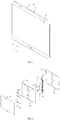
FIG. 1 is a perspective view of a foldable mobile terminal in an unfolded state according to some embodiments of the present disclosure. -
FIG. 2 is an exploded perspective view of the foldable mobile terminal shown inFIG. 1 . -
FIG. 3 is an exploded perspective view of the foldable mobile terminal shown inFIG. 1 , but shown from a different aspect. -
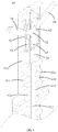
FIG. 4 is a perspective view of a foldable mechanism in a foldable mobile terminal in an unfolded state according to some embodiments of the present disclosure. -
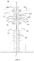
FIG. 5 is a front view of the foldable mechanism shown inFIG. 4 . -
FIG. 6 is a perspective view of the foldable mechanism ofFIG. 4 with portions omitted. -
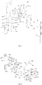
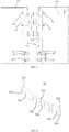
FIG. 7 is an exploded perspective view of the foldable mechanism ofFIG. 4 . -
FIG. 8 is an exploded perspective view further illustrating a partial structure ofFIG. 7 . -
FIG. 9 is an exploded perspective view of a partial structure ofFIG. 7 , but shown from a different aspect. -
FIG. 10 is a perspective view of a foldable mobile terminal with a flexible display screen omitted according to some embodiments of the present disclosure. -
FIG. 11 is a front view of a partial structure shown inFIG. 10 . -
FIG. 12 is a cross sectional view taken along a line A-A ofFIG. 11 . -
FIG. 13 is a cross sectional view from a back of the structure shown inFIG. 10 . -
FIG. 14 is a schematic view of the structure shown inFIG. 11 with some elements of the foldable mechanism omitted. -
FIG. 15 is a back view of the structure shown inFIG. 14 . -
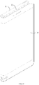
FIG. 16 is view of an elastic sheet of a foldable mechanism. -
FIG. 17 is a perspective view of a first decoration component or a second decoration component. -
FIG. 18 is a perspective view of the first decoration component or the second decoration component, but shown from a different aspect. -
FIG. 19 is a perspective view of a foldable mobile terminal in a folded state according to some embodiments of the present disclosure. -
FIG. 20 is a perspective view of the foldable mobile terminal shown inFIG. 19 with a flexible display screen omitted. -
FIG. 21 a perspective view of the foldable mobile terminal shown inFIG. 4 in an unfolded state. -
FIG. 22 is a front view of the foldable mechanism shown inFIG. 21 . -
FIG. 23 is a sectional view of a partial structure of a foldable mobile terminal in an unfolded state according to some embodiments of the present disclosure. -
FIG. 24 is a sectional view of a partial structure of a foldable mobile terminal in a semi-folded (or a semi-unfolded) state according to some embodiments of the present disclosure. -
FIG. 25 is a sectional view of a partial structure of a foldable mobile terminal in a folded state according to some embodiments of the present disclosure. - As shown in
FIG. 1, FIG. 2 ,FIG. 3, and FIG. 4 , according to some embodiments of the present disclosure, a foldable mobile terminal may be provided. The foldable mobile terminal includes aflexible display screen 10, afoldable mechanism 20, and ashell assembly 30. Theshell assembly 30 may include afirst shell 31 and asecond shell 32. Thefoldable mechanism 20 may be connected between thefirst shell 31 and thesecond shell 32. Theflexible display screen 10 may be arranged on thefirst shell 31 and thesecond shell 32. The foldable mobile terminal shown inFIG. 1 may be in an unfolded state, and thefirst shell 31 and thesecond shell 32 may be symmetric to each other with respect to thefoldable mechanism 20. As shown inFIG. 19 , when thefirst shell 31 and thesecond shell 32 rotates to reach a completely folded state with respect to thefoldable mechanism 20, theflexible display screen 10 may be arranged at an outside of themobile terminal 10. As shown inFIG. 1 , in the unfolded state, an extending length of a side of theshell assembly 30 facing towards the flexible display screen 10 (the length along a direction parallel to an X-axis shown inFIG. 1 ) may be equal to an extending length of a side of theshell assembly 30 facing away from the flexible display screen 10 (the length along the direction parallel to the X-axis shown inFIG. 1 ). However, as shown inFIG. 19 , theshell assembly 30 itself may have a thickness (the thickness is along a direction parallel to an Y-axis shown inFIG. 1 ), in a folded state, the extending length of the side of theshell assembly 30 facing towards theflexible display screen 10 may be greater than the extending length of the side of theshell assembly 30 facing away from theflexible display screen 10. By providing thefoldable mechanism 20, thefirst shell 31 and thesecond shell 32 may adapt to a length difference generated while switching between the folded state and the unfolded state. - The
first shell 31 may include a firstfront shell 311 and afirst back shell 312 connected to each other. Thesecond shell 32 may include a secondfront shell 321 and asecond back shell 322 connected to each other. The connection may be achieved by screwing, adhesion, welding, and the like. Theflexible display screen 10 may be disposed on the firstfront shell 311 and the secondfront shell 321. Theflexible display screen 10 may have a display region, and the display region may be rectangular or rounded rectangular in the unfolded state. A space may be formed between the firstfront shell 311 and thefirst back shell 312 along the direction parallel to the Y-axis. Similarly, a space may be formed between the secondfront shell 321 and thesecond back shell 322 along the direction parallel to the Y-axis. The spaces may allow arrangement of a power module, a communication module, and other components. The spaces may further allow thefoldable mechanism 20 to slidably extend and retract with respect to thefirst shell 31 and thesecond shell 32; that is to say, thefoldable mechanism 20 is slidable away from or towards thefirst shell 31 and thesecond shell 32. - Another space may be formed between the
first shell 31 and thesecond shell 32 along the direction parallel to the X-axis. The foldable mechanism may be arranged within the space between thefirst shell 31 and thesecond shell 32 along the direction parallel to the X-axis, and at least a partial structure of thefoldable mechanism 20 may be received in thefirst shell 31 and thesecond shell 32. The space between thefirst shell 31 and thesecond shell 32 along the direction parallel to the X-axis may be changed during the rotation of thefirst shell 31 and the second shell around thefoldable mechanism 20. Therefore, during the rotation of thefirst shell 31 and thesecond shell 32 around thefoldable mechanism 20, thefoldable mechanism 20 may be retracted into thefirst shell 31 and thesecond shell 32 at varying levels. As shown inFIG. 4 andFIG. 5 , thefoldable mechanism 20 may include afirst rotation assembly 50 and asecond rotation assembly 60. Thefirst rotation assembly 50 may be connected to thefirst shell 31. Therotation assembly 50 may be at least partially received inside thefirst shell 31, and may slidably extend and retract with respect to (i.e., slide away from or towards) thefirst shell 31. Thesecond rotation assembly 60 may be connected to thesecond shell 32. Thesecond rotation assembly 60 may be at least partially received insidesecond shell 32, and may slidably extend and retract with respect to (slide away from or towards) thesecond shell 32. By the slidable extension and retraction of thefirst rotation assembly 50 with respect to thefirst shell 31 and the slidable extension and retraction of thesecond rotation assembly 60 with respect to thesecond shell 32, thefirst shell 31 and thesecond shell 32 may adapt to a length difference generated while switching between the folded state and the unfolded state. - In some embodiments, the
first rotation assembly 50 and thesecond rotation assembly 60 may have a same structure. Thefirst rotation assembly 50 and thesecond rotation assembly 60 may be symmetrically distributed about a central axis I-I (shown inFIG. 5 ) between thefirst rotation assembly 50 and thesecond rotation assembly 60. By arranging thefirst rotation assembly 50 and thesecond rotation assembly 60 to be symmetric to each other, thefirst shell 31 and thesecond shell 32 may be folded and unfolded symmetrically about the central axis I-I. - As further shown in
FIG. 4 ,FIG. 5 ,FIG. 6 , andFIG. 7 , thefirst rotation assembly 50 includes a first slidingplate 51, afirst rotation shaft 53, and afirst connection rod 54. Thefirst rotation shaft 53 is arranged on the first slidingplate 51. Afirst end 541 of thefirst connection rod 54 is slidably hinged to thefirst rotation shaft 53, and asecond end 542 of thefirst connection rod 54 is rotatably connected to thefirst shell 31. The first slidingplate 51 is capable of being at least partially received in thefirst shell 31, and slidably extend and retract with respect to (i.e., slide away from or towards) thefirst shell 31. While thefirst shell 31 and thesecond shell 32 folds and unfolds symmetrically, the first slidingplate 51 together with thefirst rotation shaft 53 is capable to may- slidably extend and retract with respect to (i.e., slide away from or towards) thefirst shell 31. Thesecond end 542 of thefirst connection rod 54 may rotate with respect to thefirst shell 31. Thefirst end 541 of thefirst connection rod 54 may slide on thefirst rotation shaft 53 and rotate with respect to thefirst rotation shaft 53. By changing a level at which the first slidingplate 51 is received inside thefirst shell 31,it is possible to adapt to a length difference generated during the folding and unfolding of thefirst shell 31 and thesecond shell 32. - According to some embodiments shown in
FIG. 2 andFIG. 3 , twofirst rotation shafts 53 and twofirst connection rods 54 may be arranged on the first slidingplate 51. The twofirst rotation shafts 53 may be arranged symmetrically about a middle position of the first slidingplate 51 along a direction parallel to a Z-axis, and the twofirst connection rods 54 may be arranged symmetrically about a middle position of the first slidingplate 51 along the direction parallel to the Z-axis. In some other embodiments, the number of thefirst rotation shaft 53 may be one or more, and the number of thefirst connection rod 54 may be one or more. Slidable extension and retraction of the first slidingplate 51 with respect to thefirst shell 31 may be achieved with various numbers of thefirst rotation shafts 53 and thefirst connection rods 54. - As shown in
FIG. 4 ,FIG. 5 ,FIG. 6 , andFIG. 7 , thesecond rotation assembly 60 includes a second slidingplate 61, asecond rotation shaft 63, and asecond connection rod 64. Thesecond rotation shaft 63 may be arranged on the second slidingplate 61. Afirst end 641 of thesecond connection rod 64 is slidably hinged to thesecond rotation shaft 63, and asecond end 642 of thesecond connection rod 64 is rotatably connected to thesecond shell 32. The second slidingplate 61 is capable of being at least partially received in thesecond shell 32, and slidably extend and retract with respect to (i.e., slide away from or towards) thesecond shell 32. While thefirst shell 31 and thesecond shell 32 folds and unfolds symmetrically, the second slidingplate 61 together with thesecond rotation shaft 63 is capable to slidably extend and retract with respect to (i.e., slide away from or towards) thesecond shell 32. Thesecond end 642 of thesecond connection rod 64 may rotate with respect to thesecond shell 32. Thefirst end 641 of thesecond connection rod 64 may slide on thesecond rotation shaft 63 and rotate with respect to thesecond rotation shaft 63. By changing a level at which the second slidingplate 61 is received in thesecond shell 32, it is possible to adapt to a length difference generated during the folding and unfolding of thefirst shell 31 and thesecond shell 32. - According to some embodiments shown in
FIG. 2 andFIG. 3 , twosecond rotation shafts 63 and twosecond connection rods 64 may be arranged on the second slidingplate 61. The twosecond rotation shafts 63 may be arranged symmetrically about a middle position of the second slidingplate 61 along the direction parallel to the Z-axis, and the twosecond connection rods 64 may be arranged symmetrically about a middle position of the second slidingplate 61 along the direction parallel to the Z-axis. In some other embodiments, the number of thesecond rotation shafts 63 may be one or more, and the number of thesecond connection rods 64 may be one or more. Slidable extension and retraction of the second slidingplate 61 with respect to thesecond shell 32 may be achieved with various numbers of thesecond rotation shafts 63 and thesecond connection rods 64. - As shown in
FIG. 8 andFIG. 9 , in some embodiments, thefoldable mechanism 20 may include alinkage element 22 connected to thefirst rotation shaft 53 and thesecond rotation shaft 63. Thelinkage element 22 may have a first throughhole 221 and a second throughhole 222. The first throughhole 221 and the second throughhole 222 may be spaced apart from each other. Thefirst rotation shaft 53 may be arranged to extend through the first throughhole 221, and thesecond rotation shaft 63 may be arranged to extend through the second throughhole 222. Thelinkage element 22 may link thefirst end 541 of thefirst connection rod 54 and thefirst end 641 of thesecond connection rod 64 to move at the same time. That is, by virtue of thelinkage element 22, sliding of thefirst end 541 of thefirst connection rod 54 along thefirst rotation shaft 53 may lead to sliding of thefirst end 641 of thesecond connection rod 64 along thesecond rotation shaft 63, and vice versa. - The
linkage element 22 may allow thefirst connection rod 54 which is slidably hinged to thefirst rotation shaft 53 and thesecond connection rod 64 which is slidably hinged to thesecond rotation shaft 63 to move synchronously. That is, the slidable extension and retraction of the first slidingplate 51 with respect to thefirst shell 31 is synchronous with the slidable extension and retraction of the second slidingplate 61 with respect to thesecond shell 32, such that a symmetric folding and unfolding of thefirst shell 31 and thesecond shell 32 may be further achieved. Thelinkage element 22 may be made of metals or plastics. - In other embodiments, functions of the
linkage element 22 may be achieved by other components. For example, a component configured to achieve a slidable hinge between thefirst connection rod 54 and thefirst rotation shaft 53 and a component configured to achieve a slidable hinge between thesecond connection rod 64 and thesecond rotation shaft 63 may be configured as an integral component. By configuring an integral component to achieve the slidable hinge, thefirst connection rod 54 which is slidably hinged to thefirst rotation shaft 53 and thesecond connection rod 64 which is slidably hinged to thesecond rotation shaft 63 may move synchronously. - As shown in
FIG. 7, FIG. 8 , andFIG. 9 , in some embodiments, thefirst rotation assembly 50 may further include a first slidingmember 52 configured to achieve the slidable hinge between thefirst connection rod 54 and thefirst rotation shaft 53. The first slidingmember 52 may be arranged to slidably sleeve on thefirst rotation shaft 53, and thefirst end 541 of thefirst connection rod 54 may be rotatably connected to the first slidingmember 52. - In some embodiments, the first sliding
member 52 may include twosleeve tubes 521 and aconnection arm 522 connected between the twosleeve tubes 521. Thefirst rotation shaft 53 may extend through thesleeve tubes 521 of the first slidingmember 52. The first slidingmember 52 may slide along thefirst rotation shaft 53 and rotate with respect to thefirst rotation shaft 53. - The
first end 541 of thefirst connection rod 54 may be rotatably connected to theconnection arm 522 of the first slidingmember 52. Further, theconnection arm 522 of the first slidingmember 52 may have afirst positioning hole 523, and thefirst end 541 of thefirst connection rod 54 may have afirst positioning protrusion 543. Thefirst positioning protrusion 543 may be inserted into thefirst positioning hole 523. - The
second rotation assembly 60 may further include a second slidingmember 62. The slidable hinge between thesecond connection rod 64 and thesecond rotation shaft 63 may be achieved by the second slidingmember 62. The second slidingmember 62 may be arranged to sleeve on thesecond rotation shaft 63 in a slidable manner, and thefirst end 641 of thesecond connection rod 64 may be rotatably connected to the second slidingmember 62. - In some embodiments, the second sliding
member 62 may include twosleeve tubes 621 and aconnection arm 622 connected between the twosleeve tubes 621. Thesecond rotation shaft 63 may extend through thesleeve tubes 621 of the second slidingmember 62. The second slidingmember 62 may slide along thesecond rotation shaft 63 and rotate with respect to thesecond rotation shaft 63. - The
first end 641 of thesecond connection rod 64 may be rotatably connected to theconnection arm 622 of the second slidingmember 62. Further, theconnection arm 622 of the second slidingmember 62 may have asecond positioning hole 623, and afirst end 641 of thesecond connection rod 64 may have asecond positioning protrusion 643. Thesecond positioning protrusion 643 may be inserted into thesecond positioning hole 623. - In some embodiments, the
linkage element 22 may include afirst arm portion 223 having the first throughhole 221 and asecond arm portion 224 having the second throughhole 222. Thefirst arm portion 223 may be arranged between the twosleeve tubes 521 of the first slidingmember 52. Thesecond arm portion 224 may be arranged between the twosleeve tubes 621 of the second slidingmember 62. Thefirst rotation shaft 53 may extend through the first throughhole 221, and thesecond rotation shaft 63 may extend through the second throughhole 222. Thelinkage element 22 may serve as a link between the first slidingmember 52 and the second slidingmember 62, such that the sliding of the first slidingmember 52 along thefirst rotation shaft 53 may be synchronous with the sliding of the second slidingmember 62 along thesecond rotation shaft 63. - As shown in
FIG. 4 ,FIG. 5 ,FIG. 6 , andFIG. 7 , in some embodiments, thefirst rotation assembly 50 may further include afirst support 56, and thefirst rotation shaft 53 may be configured on the first slidingplate 51 through thefirst support 56. Further, thefirst support 56 may be fixed on the first slidingplate 51 by screw fastening. Thefirst rotation shaft 53 may extend through thefirst support 56, and the second slidingmember 52 may be arranged between thefirst support 56 and the first slidingplate 51. By arranging thefirst support 56, relative movement of the first slidingmember 52, thefirst end 541 of thefirst connection rod 54, and thefirst rotation shaft 53 may be restricted within a space between thefirst support 56 and the first slidingplate 51, such that thefirst end 541 of thefirst connection rod 54 may be prevented from detaching from the first slidingmember 52. - The rotatable connection between the
second end 542 of thefirst connection rod 54 and thefirst shell 31 may be achieved by a rotatable connection between thesecond end 542 of thefirst connection rod 54 and the firstfront shell 311. Alternatively, the rotatable connection between thesecond end 542 of thefirst connection rod 54 and thefirst shell 31 may be achieved by a rotatable connection between thesecond end 542 of thefirst connection rod 54 and thefirst back shell 312. Alternatively, the rotatable connection between thesecond end 542 of thefirst connection rod 54 and thefirst shell 31 may be achieved by rotatably connecting thesecond end 542 of thefirst connection rod 54 to the firstfront shell 311 and thefirst back shell 312 at the same time. In some embodiments, as shown inFIG. 8 ,FIG. 9 , andFIG. 11 , the firstfront shell 311 may have a first connection hole 313, and afirst connection protrusion 544 may be arranged at thesecond end 542 of thefirst connection rod 54. Thefirst connection protrusion 544 may be inserted into the first connection hole 313. Further, as shown inFIG. 13 andFIG. 15 , thefirst rotation assembly 50 may further include a firstpressing sheet 55. The firstpressing sheet 55 may be connected to the firstfront shell 311, and configured to limit a position of thefirst connection rod 54, such that thefirst connection rod 54 may be disposed between the firstpressing sheet 55 and the firstfront shell 311. - As shown in
FIG. 4 ,FIG. 5 ,FIG. 6 , andFIG. 7 , in some embodiments, thesecond rotation assembly 60 may further include asecond support 66, and thesecond rotation shaft 63 may be configured on the second slidingplate 61 through thesecond support 66. Further, thesecond support 66 may be fixed on the second slidingplate 61 by screw fastening. Thesecond rotation shaft 63 may extend through thesecond support 66, and the second slidingmember 62 may be arranged between thesecond support 66 and the second slidingplate 61. By arranging thesecond support 66, relative movement of the second slidingmember 62, thefirst end 641 of thesecond connection rod 64, and thesecond rotation shaft 63 may be restricted within a space between thesecond support 66 and the second slidingplate 61, such that thefirst end 641 of thesecond connection rod 64 may be prevented from detaching from the second slidingmember 62. - The rotatable connection between the
second end 642 of thesecond connection rod 64 and thesecond shell 32 may be achieved by a rotatable connection between thesecond end 642 of thesecond connection rod 64 and the secondfront shell 321. Alternatively, the rotatable connection between thesecond end 642 of thesecond connection rod 64 and thesecond shell 32 may be achieved by a rotatable connection between thesecond end 642 of thesecond connection rod 64 and thesecond back shell 322. Alternatively, the rotatable connection between thesecond end 642 of thesecond connection rod 64 and thesecond shell 32 may be achieved by rotatably connecting thesecond end 642 of thesecond connection rod 64 to the secondfront shell 321 and thesecond back shell 322 at the same time. In some embodiments, as shown inFIG. 8 ,FIG. 9 , andFIG. 11 , the secondfront shell 321 may have asecond connection hole 323, and asecond connection protrusion 644 may be arranged at thesecond end 642 of thesecond connection rod 64. Thesecond connection protrusion 644 may be inserted into thesecond connection hole 323. Further, as shown inFIG. 13 andFIG. 15 , thesecond rotation assembly 60 may further include a secondpressing sheet 65. The secondpressing sheet 65 may be connected to the secondfront shell 321, and configured to limit a position of thesecond connection rod 64, such that thesecond connection rod 64 may be disposed between the secondpressing sheet 65 and the secondfront shell 321. - As shown in
FIG. 8 andFIG. 9 , thefoldable mechanism 20 may further include afirst shaft sleeve 24a and asecond shaft sleeve 24b. Thefirst shaft sleeve 24a may be disposed at one end of thefirst rotation shaft 53 and one end of thesecond rotation shaft 63, and may be connected to both thefirst rotation shaft 53 and thesecond rotation shaft 63. Thesecond shaft sleeve 24b may be disposed at the other end of thefirst rotation shaft 53 and the other end of thesecond rotation shaft 63, and may be connected to both thefirst rotation shaft 53 and thesecond rotation shaft 63. The first and thesecond shaft sleeves first rotation shaft 53 on thefirst support 56, and fix thesecond rotation shaft 63 on thesecond support 66. Thefirst support 56, thesecond support 66, thefirst rotation shaft 53, and thesecond rotation shaft 63 may be provided with equal number. In some embodiments, the number of the first supports 56 and the number of the second supports 66 may both be two. Eachfirst support 56 may be arranged at a corresponding end of the first slidingplate 51 along the direction parallel to the Z-axis, and eachsecond support 66 may be arranged at a corresponding end of the second slidingplate 61 along the direction parallel to the Z-axis. - In some embodiments, as shown in
FIG. 4 andFIG. 7 , thefoldable mechanism 20 may further include asupportive strip 26. Thesupportive strip 26 may be arranged between thefirst rotation assembly 50 and thesecond rotation assembly 60. Thesupportive strip 26 may be configured to support theflexible display screen 10. Thesupportive strip 26 may extend for a certain length along the direction parallel to the Z-axis in order to be arranged in a gap between the first slidingplate 51 and the second slidingplate 61. According to some embodiments provided with thefirst support 56 and thesecond support 66, thesupportive strip 26 may further extend into a gap between thefirst support 56 and thesecond support 66. Thesupportive strip 26, the first slidingplate 51, the second slidingplate 61, thefirst support 56, thesecond support 66, the firstfront shell 311, and the secondfront shell 321 may cooperatively support theflexible display screen 10. - As shown in
FIG. 8 andFIG. 9 , thelinkage element 22 may have a receivingrecess 226. At least a partial structure of the supportive strip may be received in the receivingrecess 226. In some embodiments, thelinkage element 22 may include aconnection portion 225 connecting with thefirst arm portion 223 and thesecond arm portion 224, and the receivingrecess 226 may be formed on theconnection portion 225. - As shown in
FIG. 8 andFIG. 9 , in other embodiments, at least one of thefirst shaft sleeve 24a and thesecond shaft sleeve 24b may also have a receivingrecess 241, and at least a partial structure of thesupportive strip 26 may be received in the receivingrecess 241. At least one of the connection between thesupportive strip 26 and thefirst shaft sleeve 24a and thesecond shaft sleeve 24b and the connection between thesupportive strip 26 and thelinkage element 22 may be achieved by welding or other means. - As shown in
FIG. 20 ,FIG. 23 ,FIG. 24, and FIG. 25 , atop face 261 of thesupportive strip 26 faces towards theflexible display screen 10, and thetop face 261 of thesupportive strip 26 may be a curved face. When the foldable mobile terminal is in a semi-folded state as shown inFIG. 24 or in a folded state as shown inFIG. 25 , as thesupportive strip 26 has a curved face, a curvature of a contour of the mobile terminal may not be changed sharply during the folding of thefirst shell 31 and thesecond shell 32. Therefore, theflexible display screen 10 may be better supported. - As shown in
FIG. 7, FIG. 8 , andFIG. 9 , in some embodiments, thefirst rotation assembly 50 may further include a firstelastic sheet 57 arranged on the first slidingplate 51. Thefirst end 541 of thefirst connection rod 54 may reach two extreme positions along a direction of sliding, the firstelastic sheet 57 may include two first engagingportions 571. Each of the two first engagingportions 571 may correspond to each of the two extreme positions. In the embodiments provided with thefirst support 56, the firstelastic sheet 57 may be fixed on the first slidingplate 51 through thefirst support 56, and the firstelastic sheet 57 may be disposed inside thefirst support 56. - The two first engaging
portions 571 of the firstelastic sheet 57 may respectively correspond to two ends of a sliding path of thefirst end 541 of thefirst connection rod 54 while thefirst end 541 slides along thefirst rotation shaft 53. To some extent, interference may be generated between each first engagingportion 571 and thefirst end 541 of thefirst connection rod 54, such that the first engagingportion 571 may apply a clamping force to thefirst end 541 of thefirst connection rod 54, and the position of thefirst connection rod 54 may not be changed randomly. Therefore, the first slidingplate 51 may be arranged at a stable position with respect to thefirst shell 31, that is, the foldable mobile terminal may stably remain in the folded or unfolded state. - In some embodiments, the
first positioning protrusion 543 at thefirst end 541 of thefirst connection rod 54 may extend through two opposing sides of thefirst end 541. An end of thefirst positioning protrusion 543 may be engaged in thefirst positioning hole 523 of the first slidingmember 52, and an opposing end of thefirst positioning protrusion 543 may be inserted into the first engagingportion 571 of the firstelastic sheet 57. The firstengaging portion 571 may clamp thefirst positioning protrusion 543 to apply a certain clamping force to thefirst connection rod 54. - In some embodiments, the first
elastic sheet 57 may further include a first dampingportion 572 disposed between the two first engagingportions 571. When thefirst end 541 of thefirst connection rod 54 slides from the first engagingportion 571 to the first dampingportion 572, a resistance may be increased. Increasing of the resistance may be achieved as a clamping force applied to thefirst positioning protrusion 543 by the first dampingportion 572 is greater than the clamping force applied to thefirst positioning protrusion 543 by the first engagingportion 571. For example, the firstelastic sheet 57 may be stadium-shaped with an opening at an end and closed at an opposing end. The two first engagingportions 571 may be arranged at the two opposite ends of the firstelastic sheet 57, and the first dampingportion 572 may be arranged at a middle portion of the firstelastic sheet 57. A first gap 572a formed in the first dampingportion 572 for thefirst positioning protrusion 543 to extend through may be smaller than asecond gap 571a formed in the first engagingportion 571 for thefirst positioning protrusion 543 to extend through. Therefore, during the sliding from the first engagingportion 571 to the first dampingportion 572, thefirst connection rod 54 may receive an increased resistance. By arranging the firstelastic sheet 57 in such manner, when rotating thefirst shell 31 and thesecond shell 32 of the foldable mobile terminal, a user may feel the resistance more obviously. - In some other embodiments, the first
elastic sheet 57 may be in shape of a closed loop. Further, in yet other embodiments, the firstelastic sheet 57 may include two separated strips. Two ends of each of the two separated strips may be fixed on the first slidingplate 51 through thefirst support 56 or other components (or by other means), such that thefirst connection rod 54 may be applied with different resistances when thefirst connection rod 54 is at various positions of the sliding path along thefirst rotation shaft 53. - As shown in
FIG. 9 , thefirst support 56 may have a first receivingcavity 560, and the firstelastic sheet 57 may be received in the first receivingcavity 560. After thefirst support 56 is fixed on the first slidingplate 51, the first slidingplate 51 may close the first receivingcavity 560, such that the firstelastic sheet 57 may be fixed inside the first receivingcavity 560. - Further, the first receiving
cavity 560 may include twofirst positioning cavities 561 and a first releasingcavity 562. Each of the twofirst positioning cavities 561 may correspond to each of the first engagingportion 571 of the firstelastic sheet 57. The first releasingcavity 562 may be formed between the twofirst positioning cavities 561. A size of the first releasingcavity 562 may be greater than a size of eachfirst positioning cavity 561. After the first engagingportion 571 is arranged in thefirst positioning cavity 561, the first engagingportion 571 may be fixed to be unmovable. The first dampingportion 572 arranged between the two first engagingportions 571 may be correspondingly arranged in the first releasingcavity 562. The first releasingcavity 562 may offer a space allowing the first dampingportion 572 to be elastically deformed. - In some embodiments, the
second rotation assembly 60 may further include a secondelastic sheet 67 arranged on the second slidingplate 61. Thefirst end 641 of thesecond connection rod 64 may reach two extreme positions along a direction of sliding, and the secondelastic sheet 67 may include two secondengaging portions 671. Each of the two secondengaging portions 671 may correspond to each of the two extreme positions. In the embodiments provided with thesecond support 66, the secondelastic sheet 67 may be fixed on the second slidingplate 61 through thesecond support 66, and the secondelastic sheet 67 may be disposed inside thesecond support 66. - The two second
engaging portions 671 of the secondelastic sheet 67 may respectively correspond to two ends of a sliding path of thefirst end 641 of thesecond connection rod 64 while thefirst end 641 slides along thesecond rotation shaft 63. To some extent, interference may be generated between each second engagingportion 671 and thefirst end 641 of thesecond connection rod 64, such that the secondengaging portion 671 may apply a clamping force to thefirst end 641 of thesecond connection rod 64, and the position of thesecond connection rod 64 may not be changed randomly. Therefore, the second slidingplate 61 may be arranged at a stable position with respect to thesecond shell 32, that is the foldable mobile terminal may stably remain in the folded or unfolded state. - In some embodiments, the
second positioning protrusion 643 at thefirst end 641 of thesecond connection rod 64 may extend through two opposing sides of thefirst end 641. An end of thesecond positioning protrusion 643 may be engaged in thesecond positioning hole 623 of the second slidingmember 62, and an opposing end of thesecond positioning protrusion 643 may be inserted into the secondengaging portion 671 of the secondelastic sheet 67. The secondengaging portion 671 may clamp thesecond positioning protrusion 643 to apply a certain clamping force to thesecond connection rod 64. - As shown in
FIG. 4 ,FIG. 5 ,FIG. 21 , andFIG. 22 ,FIG. 5 illustrates the slidingmechanism 20 in the unfolded state, and thesecond positioning protrusion 643 arrange at thefirst end 641 of thesecond connection rod 64 may be inserted into one of the secondengaging portions 671, as shown inFIG. 5 .FIG. 22 illustrates the slidingmechanism 20 in the folded state, and thesecond positioning protrusion 643 arrange at thefirst end 641 of thesecond connection rod 64 may be inserted into the other one of secondengaging portions 671, as shown inFIG. 22 . - In some embodiments, the second
elastic sheet 67 may further include a second dampingportion 672 disposed between the two secondengaging portions 671. When thefirst end 641 of thesecond connection rod 64 slides from the secondengaging portion 671 to the second dampingportion 672, a resistance may be increased. Increasing of the resistance may be achieved as a clamping force applied to thesecond positioning protrusion 643 by the second dampingportion 672 is greater than the clamping force applied to thesecond positioning protrusion 643 by the secondengaging portion 671. For example, the secondelastic sheet 67 may be stadium-shaped with an opening at an end and closed at an opposing end. The two secondengaging portions 671 may be arranged at two ends of the secondelastic sheet 67, and the second dampingportion 672 may be arranged at a middle portion of the secondelastic sheet 67. Athird gap 672a formed in the second dampingportion 672 for thesecond positioning protrusion 643 to extend through may be smaller than a fourth gap 671a formed in the secondengaging portion 671 for thesecond positioning protrusion 643 to extend through. Therefore, during the sliding from the secondengaging portion 671 to the second dampingportion 672, thesecond connection rod 64 may receive an increased resistance. By arranging the secondelastic sheet 67 in this manner, when rotating thefirst shell 31 and thesecond shell 32 of the foldable mobile terminal, the user may feel the resistance more obviously. - In some other embodiments, the second
elastic sheet 67 may be in shape of a closed loop. Further, in yet other embodiments, the secondelastic sheet 67 may include two separated strips. Two ends of each of the two separated strips may be fixed on the second slidingplate 61 through thesecond support 66 or other components (or by other means), such that thesecond connection rod 64 may be applied with different resistances when thesecond connection rod 64 is at various positions of the sliding path along thesecond rotation shaft 63. - As shown in
FIG. 9 , thesecond support 66 may have asecond receiving cavity 660, and the secondelastic sheet 67 may be received in the second receivingcavity 660. After thesecond support 66 is fixed on the second slidingplate 61, the second slidingplate 61 may close the second receivingcavity 660, such that the secondelastic sheet 67 may be fixed inside the second receivingcavity 660. - Further, the second receiving
cavity 660 may include twosecond positioning cavities 661 and a second releasingcavity 662. Each of the twosecond positioning cavities 661 may correspond to each second engagingportion 671 of the secondelastic sheet 67. The second releasingcavity 662 may be formed between the twosecond positioning cavities 661. A size of the second releasingcavity 662 may be greater than a size of eachsecond positioning cavity 661. After the secondengaging portion 671 is arranged in thesecond positioning cavity 661, the secondengaging portion 671 may be fixed to be unmovable. The second dampingportion 672 arranged between the two secondengaging portions 671 may be arranged in the second releasingcavity 662. The second releasingcavity 662 may offer a space allowing the second dampingportion 672 to be elastically deformed. - As shown in
FIG. 10 ,FIG. 11, and FIG. 12 , in some embodiments, the foldable mobile terminal may further include a joiningsheet 70 and twopressing elements 71. The joiningsheet 70 may cross over thefirst rotation assembly 50 and thesecond rotation assembly 60, and each end of the joiningsheet 70 may be rotatably connected to thefirst shell 31 and thesecond shell 32 through each of the twopressing elements 71 respectively. A change of the length generated during the rotation of thefirst shell 31 and thesecond shell 32 may adapt by the extension and retraction of thefirst rotation assembly 50 and thesecond rotation assembly 60 of the slidingmechanism 20 with respect to thefirst shell 31 and thesecond shell 32, respectively. In this way, a contour of the foldable mobile terminal may be uniform and complete during folding and unfolding. By arranging the joiningsheet 70, thefirst shell 31 and thesecond shell 32 may be protected from being overly stretched, and theflexible display screen 10 may be prevented from being damaged by the stretching. - As shown in
FIG. 16 , afirst end 701 of the joiningsheet 70 may have a firstelongated hole 703, and asecond end 702 of the joiningsheet 70 may have a secondelongated hole 704. One of thepressing elements 71 may extend through the firstelongated hole 703, and be further fixedly connected to thefirst shell 31, and the other of thepressing elements 71 may extend through the secondelongated hole 704, and be further fixedly connected to thesecond shell 32. When thefirst rotation assembly 50 slides towards and away from thefirst shell 31 and thesecond rotation assembly 60 slides towards and away from thesecond shell 32, the joiningsheet 70 may move with respect to thepressing elements 71 along a direction to which the firstelongated hole 703 and the secondelongated hole 704 elongate, that is, the joiningsheet 70 may move with respect to thefirst shell 31 and thesecond shell 32. As shown inFIG. 12 , when the foldable mobile terminal is in the unfolded state, an outer end of the firstelongated hole 703 and an outer end of the secondelongated hole 704 of the joiningsheet 70, that is, an end of the firstelongated hole 703 away from thefirst rotation assembly 50 and an end of the secondelongated hole 704 away from thesecond rotation assembly 60, may abut against the corresponding pressingelement 71. In this way, thefirst shell 31 and thesecond shell 32 may be prevented from departing from each other continually, and thefirst shell 31 and thesecond shell 32 may be protected from being overly stretched. During folding, by virtue of space of the first and the second elongated holes, the joiningsheet 70 may slide with respect to thefirst shell 31 and thesecond shell 32 to adapt to the length change of the first and thesecond shells - The joining
sheet 70 may include two joiningportions 705 respectively located at thefirst end 701 and thesecond end 702, and asupportive portion 706 connected between the two joiningportions 705. Each of the two joiningportions 705 may be connected to eachpressing element 71, and thesupportive portion 706 may be configured to support theflexible display screen 10. - In some embodiments, the
pressing element 71 may be a screw or other fastening elements. The screw or other fastening elements of one pressingelement 71 may extend through the firstelongated hole 703, and then connect the joiningsheet 70 to thefirst shell 31. The screw or other fastening elements of the other pressingelement 71 may extend through the secondelongated hole 704, and then connect the joiningsheet 70 to thesecond shell 32. In some embodiments, eachpressing element 71 may be cubic. Onepressing element 71 may be configured to press on thefirst end 701 of the joiningsheet 70, and the other pressingelement 71 may be configured to press on thesecond end 702 of the joiningsheet 70. An additional fastening element may be configured to extend through one pressingelement 71 and the firstelongated hole 703 to fasten with thefirst shell 31, and another additional fastening element may be configured to extend through the other pressingelement 71 and the secondelongated hole 704 to fasten with thesecond shell 32. For example, the firstfront shell 311 may include a first mountingportion 314, thefirst end 701 of the joiningsheet 70 may be slidably connected to the first mountingportion 314 through one of thepressing elements 71. Similarly, the secondfront shell 321 may include a second mountingportion 324, and thesecond end 702 of the joiningsheet 70 may be slidably connected to the second mountingportion 324 through the other of thepressing elements 71. - In some embodiments, a bending portion may be formed at an intersection between the
supportive portion 706 and each of the two joiningportions 705. As shown inFIG. 12 , each of the first mountingportion 314 and the second mountingportion 324 may be recessed to engage with the bending portion of the corresponding joiningsheet 70 and configured to receive the corresponding pressingelement 71. - The joining
sheet 70 may have a plurality of throughholes 700 with distance apart from each other. In some embodiments, the plurality of throughholes 700 may be formed on thesupportive portion 706. The throughholes 700 enable the joiningsheet 70 to be bent easily, such that the joiningsheet 70 may better fit with thefirst rotation assembly 50 and thesecond assembly 60, and the joiningsheet 70 may be prevented from generating crease to impact the effect of supporting theflexible display screen 10. - In some embodiments, a fixing
structure 707 connected to thesupportive strip 26 may be arranged on thesupportive portion 706. In some embodiments, the fixingstructure 707 may be a hole for welding. As the joiningsheet 70 crosses over thesupportive strip 26, the joiningsheet 70 may be fixedly connected to thesupportive strip 26 by welding. - In some embodiments, the number of the joining
sheets 70 may be two. It may be understood that, in other embodiments, the number of the joiningsheets 70 may be increased or decreased as required. - As shown in
FIG. 10 andFIG. 11 , in some embodiments, the foldable mobile terminal may further include afirst decoration component 72a and asecond decoration component 72b. Thefirst decoration component 72a may be disposed at one end of thefoldable mechanism 20 along the direction parallel to the Z-axis, further disposed in the gap formed between thefirst shell 31 and thesecond shell 32. Thesecond decoration component 72b may be disposed at the other end of thefoldable mechanism 20 along the direction parallel to the Z-axis, further disposed in the gap formed between thefirst shell 31 and thesecond shell 32. The first and thesecond decoration components foldable mechanism 20, such that the structures may not be exposed to an outside to impact the appearance. - As shown in
FIG. 11 ,FIG. 13, and FIG. 14 , the firstfront shell 311 may include afirst mating portion 315, and the secondfront shell 321 may include asecond mating portion 325. Each of thefirst decoration component 72a and thesecond decoration component 72b may be engaged with both thefirst mating portion 315 of the firstfront shell 311 and thesecond mating portion 325 of the secondfront shell 321. Each of thefirst decoration component 72a and thesecond decoration component 72b may be disposed at the corresponding end of the first slidingplate 51 and the second slidingplate 61 along the direction parallel to the Z-axis. - As shown in
FIG. 17 and FIG. 18 , a surface of each of thefirst decoration component 72a and thesecond decoration component 72b facing towards theflexible display screen 10 may be substantially flat to allow an easy configuration of theflexible display screen 10. A connective structure, such as a protrudingblock 721, may be arranged on a surface of each of thefirst decoration component 72a and thesecond decoration component 72b facing away from theflexible display screen 10 and connected to the firstfront shell 311 and the secondfront shell 321. A plurality ofridges 722 may be further arranged on the surface of each of thefirst decoration component 72a and thesecond decoration component 72b facing away from theflexible display screen 10. When the foldable mobile terminal is in the unfolded state, each of thefirst decoration component 72a and thesecond decoration component 72b may be unfolded naturally. A distance between twoadjacent ridges 722 may be gradually increased in a direction away from theflexible display screen 10. When each of thefirst decoration component 72a and thesecond decoration component 72b is bent, that is, when the foldable mobile terminal is in the folded state, theadjacent ridges 722 may contact with each other. - As shown in
FIG. 10 andFIG. 11 , thefirst shell 31 has two or morefirst notches 316 spaced apart from each other. In some embodiments, as shown inFIG. 14 andFIG. 15 , each of the two or morefirst notches 316 may be formed at a side of the firstfront shell 311 close to thefirst rotation assembly 50. Two or morefirst latches 511 are configured on the first slidingplate 51 and correspond to the two or morefirst notches 316. When the foldable mobile terminal switches between the folded state and the unfolded state, the first slidingplate 51 is received in thefirst shell 31 at varying levels. By configuring the latch on thefirst shell 31 and forming the notches in the first slidingplate 51 correspondingly, empty space between thefirst shell 31 and the first slidingplate 51 is reduced, such that theflexible display screen 10 is supported more stably and prevented from having functional damages due to a local stress. - In some embodiments, as shown in
FIG. 4 andFIG. 6 , the first slidingplate 51 may include afirst substrate 510, and thefirst latch 511 may be arranged on thefirst substrate 510. Thefirst substrate 510 may be disposed between the firstfront shell 311 and thefirst back shell 312 and may slidably extend and retract between the firstfront shell 311 and the first back shell 312 (that is, slide away from or towards the first front shell 311). Thefirst latch 511 and the firstfront shell 311 may be in a same plane. Herein, the plane may be parallel to a plane defined by the XZ-axes. Thefirst latch 511 and the firstfront shell 311 may be configured to cooperatively support theflexible display screen 10. - It may be understood that another first notch may further be formed in the first sliding
plate 51 between two adjacentfirst latches 511, and another first latch may further be arranged on the firstfront shell 311 between two adjacentfirst notches 316. Thefirst latch 511 on the first slidingplate 51 may correspond to thefirst notch 316 on the firstfront shell 311, and the first notch on the first slidingplate 51 may correspond to the first latch arranged on the firstfront shell 311. - The
second shell 32 may have two or moresecond notches 326 spaced apart from each other. In some embodiments, as shown inFIG. 14 andFIG. 15 , each of the two or moresecond notches 326 may be formed at a side of the secondfront shell 321 close to thesecond rotation assembly 60. Two or moresecond latches 611 may be configured on the second slidingplate 61 and correspond to the two or moresecond notches 326. When the foldable mobile terminal switches between the folded state and the unfolded state, the second slidingplate 61 may be received in thesecond shell 32 at varying levels. By configuring the latch on thesecond shell 32 and forming the notches in the second slidingplate 61 correspondingly, empty space between thesecond shell 32 and the second slidingplate 61 may be reduced, such that theflexible display screen 10 may be supported more stably and prevented from having functional damages due to a local stress. - In some embodiments, as shown in
FIG. 4 andFIG. 6 , the second slidingplate 61 may include asecond substrate 610, and thesecond latch 611 may be arranged on thesecond substrate 610. Thesecond substrate 610 may be disposed between the secondfront shell 321 and thesecond back shell 322 and may slidably extend and retract (that is, slide away from or towards the second front shell 321) between the secondfront shell 321 and thesecond back shell 322. Thesecond latch 611 and the secondfront shell 321 may be in a same plane parallel to a plane defined by the XZ-axes. Thesecond latch 611 and the secondfront shell 321 may be configured to cooperatively support theflexible display screen 10. - It may be understood that another second notch may further be formed in the second sliding
plate 61 between two adjacentsecond latches 611, and another second latch may further be arranged on the secondfront shell 321 between two adjacentsecond notches 326. Thesecond latch 611 on the second slidingplate 61 may correspond to thesecond notch 326 on the secondfront shell 321, and the second notch on the second slidingplate 61 may correspond to the second latch arranged on the secondfront shell 321. - As shown in
FIG. 4 , agap 512 may be formed between thefirst latch 511 on the first slidingplate 51 and thesecond latch 611 of the second slidingplate 61. At least partial structure of thesupportive strip 26 may be received in thegap 512. - As shown in
FIG. 4 andFIG. 6 , on the first slidingplate 51, an end of each of thefirst latches 511 away from thefirst shell 31 may be connected to each other to form a firstsupportive beam 513. On the second slidingplate 61, an end of each of thesecond latches 611 away from thesecond shell 32 may be connected to each other to form a secondsupportive beam 613. At least a partial structure of thesupportive strip 26 may be disposed on the firstsupportive beam 513 and the secondsupportive beam 613. - As shown in
FIG. 13 , the foldable mobile terminal may further include afirst roller 58 and afirst spring 59. Thefirst roller 58 and thefirst spring 59 may be disposed between thefirst rotation assembly 50 and thefirst shell 31. Thefirst rotation assembly 50 may have afirst groove 514. When thefirst rotation assembly 50 slidably extends and retracts with respect to (that is, slides away from or towards) thefirst shell 31, thefirst roller 58 may move into or out of thefirst groove 514, such that the user of the foldable mobile terminal may feel a standstill if the foldable mobile terminal is folded to an appropriate position. - In some embodiments, the
first roller 58 and thefirst spring 59 may be disposed between the first slidingplate 51 and thefirst back shell 312. In some other embodiments, thefirst roller 58 and thefirst spring 59 may be disposed between the first slidingplate 51 and the firstfront shell 311. According to some embodiments shown inFIG. 4 andFIG. 13 , thefirst groove 514 may be formed in a side wall of thefirst latch 511 of the first slidingplate 51 and face towards an adjacentfirst latch 511 arranged on thefirst substrate 510. - As shown in
FIG. 13 andFIG. 15 , a side wall in thefirst notch 316 may be recessed inwardly away from a correspondingfirst latch 511 to form afirst cavity 317. Thefirst roller 58 and thefirst spring 59 may be received in thefirst cavity 317. Thefirst spring 59 may abut against thefirst roller 58 to allow at least a part of thefirst roller 58 to be exposed to an outside of thefirst cavity 317, such that thefirst roller 58 may elastically abut against a side wall of the correspondingfirst latch 511. - Further, the
first latch 511 which has thefirst groove 514 may extend towards thefirst shell 31 for a distance longer than any otherfirst latch 511 extends towards thefirst shell 31, that is, a length for which thefirst latch 511 having thefirst groove 514 may extend towards thefirst shell 31 is greater than a length for which any otherfirst latch 511 may extend towards thefirst shell 31. - In some embodiments, at least two sets of the
first rollers 58 and thefirst springs 59 may be provided. Each of two opposing side walls of thefirst latch 511 may have thefirst groove 514 matching with thefirst roller 58. Correspondingly, two opposing side walls of thefirst notch 316 may be recessed away from the correspondingfirst latch 511 to form twofirst cavities 317. Each of the twofirst cavities 317 may be formed to receive one set of thefirst roller 58 and thefirst spring 59. - In some embodiments, the side wall of the
first latch 511 may have twofirst grooves 514 at two terminating positions corresponding to the first slidingplate 51. For example, one of the terminating positions may be located at an end of thefirst latch 511 close to thefirst shell 31, and the other one of the terminating positions may be located at an intersection between thefirst latch 511 and the firstsupportive beam 513. When the foldable mobile terminal is in the folded state and the unfolded state, thefirst roller 58 may respectively enter thefirst groove 514 of the corresponding one of the two terminating positions. Therefore, the user of the foldable mobile terminal may feel a standstill if the foldable mobile terminal is folded or unfolded to an appropriate position. - The foldable mobile terminal may further include a
second roller 68 and asecond spring 69. Thesecond roller 68 and thesecond spring 69 may be disposed between thesecond rotation assembly 60 and thesecond shell 32. Thesecond rotation assembly 60 may have asecond groove 614. When thesecond rotation assembly 60 slidably extends and retracts with respect to (that is, slides away from or towards) thesecond shell 32, thesecond roller 68 may move into or out of thesecond groove 614, such that the user of the foldable mobile terminal may feel a standstill if the foldable mobile terminal is folded to an appropriate position. - In some embodiments, the
second roller 68 and thesecond spring 69 may be disposed between the second slidingplate 61 and thesecond back shell 322. In some other embodiments, thesecond roller 68 and thesecond spring 69 may be disposed between the second slidingplate 61 and the secondfront shell 321. According to some embodiments shown inFIG. 4 andFIG. 13 , thesecond groove 614 may be formed in a side wall of thesecond latch 611 of the second slidingplate 61, and face towards an adjacentsecond latch 611 arranged on thesecond substrate 610. - As shown in
FIG. 13 andFIG. 15 , a side wall in thesecond notch 326 may be recessed inwardly away from a correspondingsecond latch 611 to form asecond cavity 327. Thesecond roller 68 and thesecond spring 69 may be received in thesecond cavity 327. Thesecond spring 69 may abut against thesecond roller 68 to allow at least a part of thesecond roller 68 to be exposed to an outside of thesecond cavity 327, such that thesecond roller 68 may elastically abut against a side wall of the correspondingsecond latch 611. - Further, the
second latch 611 which has thesecond groove 614 may extend towards thesecond shell 32 for a distance longer than any othersecond latch 611 extending towards thesecond shell 32, that is, a length for which thesecond latch 611 having thesecond groove 614 may extend towards thesecond shell 32 is greater than a length for which any othersecond latch 611 may extend towards thesecond shell 32. - In some embodiments, at least two sets of the
second rollers 68 and thesecond springs 69 may be provided. Each of two opposing side walls of thesecond latch 611 may have thesecond groove 614 matching with thesecond roller 68. Correspondingly, two opposing side walls of thesecond notch 326 may be recessed away from the correspondingsecond latch 611 to form twosecond cavities 327. Each of the twosecond cavities 327 may be formed to receive one set of thesecond roller 68 and thesecond spring 69. - In some embodiments, the side wall of the
second latch 611 may have twosecond grooves 614 at two terminating positions corresponding to the second slidingplate 61. For example, one of the two terminating positions may be located at an end of thesecond latch 611 close to thesecond shell 32, and the other one of the two terminating positions may be located at an intersection between thesecond latch 611 and the secondsupportive beam 613. When the foldable mobile terminal is in the folded state and the unfolded state, thesecond roller 68 may respectively enter thesecond groove 614 of the corresponding one of the two terminating positions. Therefore, the user of the foldable mobile terminal may feel a standstill if the foldable mobile terminal is folded or unfolded to an appropriate position. - Technical features of the above-mentioned embodiments may be combined by any means. To provide a concise description, not all of the possible combinations of the technical features are described herein. However, as long as no contradiction is generated, any combination of the technical features should be within the scope of the present disclosure.
- The above mentioned embodiments may illustrate only some implementations of the present disclosure. The description may be quite specific and detailed, but should not be considered to limit the scope of the present disclosure. It should be noted that, any ordinary skilled in the art, without departing from the concept of the present disclosure, may perform various transformation and improvement which should be within the scope of the present disclosure. Therefore, the scope of the present disclosure shall be subject to the claims.
Claims (13)
- A foldable mobile terminal with a foldable mechanism (20),
comprising a first shell (31) and a second shell (32) engaged with each other, and a flexible display screen (10) disposed on the first shell (31) and the second shell (32), wherein the foldable mechanism (20) comprises:a first rotation assembly (50), comprising:a first sliding plate (51), capable of being at least partially received in the first shell (31) and able to slide towards or away from the first shell (31);a first rotation shaft (53), arranged on the first sliding plate (51); anda first connection rod (54), wherein a first end (541) of the first connection rod (54) is slidably hinged to the first rotation shaft (53), and a second end (542) of the first connection rod (54) is capable of being rotatably connected to the first shell (31); anda second rotation assembly (60), comprising:a second sliding plate (61), capable of being at least partially received in the second shell (32) and able to slide towards or away from the second shell (32);a second rotation shaft (63), arranged on the second sliding plate (61); anda second connection rod (64), wherein a first end (641) of the second connection rod (64) is slidably hinged to the second rotation shaft (63), and a second end (642) of the second connection rod (64) is capable of being rotatably connected to the second shell (32),wherein the foldable mobile terminal is characterized in that the first shell (31) has two or more first notches (316) spaced apart from each other, two or more first latches (511) are arranged on the first sliding plate (51) and correspond to the two or more first notches (316), and the first sliding plate (51), the second sliding plate (52), the first shell (31), and the second shell (32) are configured to support the flexible display screen (10). - The foldable mobile terminal according to claim 1, wherein
the second shell (32) has two or more second notches (326) spaced apart from each other;
the second sliding plate (61) is arranged with two or more second latches (611); and
the two or more second latches (611) are capable of being arranged to correspond to the two or more second notches (326). - The foldable mobile terminal according to claim 2, wherein
the first sliding plate (51) comprises a first substrate (510), the two or more first latches (511) are arranged on the first substrate (510); and
the second sliding plate (61) comprises a second substrate (610), and the two or more second latches (611) are arranged on the second substrate (610). - The foldable mobile terminal according to claim 3, wherein
the first shell (31) comprises a first front shell (311) and a first back shell (312) engaged with each other;
the second shell (32) comprises a second front shell (321) and a second back shell (322) engaged with each other;
a flexible display screen (10) is capable of being arranged on the first front shell (311) and the second front shell (321);
the two or more first notches (316) are capable of being formed on the first front shell (311), the two or more second notches (326) are capable of being formed on the second front shell (321); and
the first substrate (510) is capable of being arranged between the first front shell (311) and the first back shell (312), and the second substrate (610) is capable of being arranged between the second front shell (321) and the second back shell (322). - The foldable mobile terminal according to claim 4, further comprising a first pressing sheet (55), wherein the first pressing sheet (55) is capable of being connected to the first front shell (311), and the first pressing sheet (55) is configured to limit the first connection rod (54) to be capable of being disposed between the first pressing sheet (55) and the first front shell (311).
- The foldable mobile terminal according to claim 4 or 5, further comprising a second pressing sheet (65), wherein the second pressing sheet (65) is capable of being connected to the second front shell (321), and the second pressing sheet (65) is configured to limit the second connection rod (64) to be capable of being disposed between the second pressing sheet (65) and the second front shell (321).
- The foldable mobile terminal according to any one of claims 3 to 6, further comprising a supportive strip (26), wherein a gap is formed between the two or more first latches (511) and the two or more second latches (611), and at least a part of the supportive strip (26) is received in the gap.
- The foldable mobile terminal according to claim 7, wherein ends of the two or more first latches (511) away from the first shell (31) are connected to each other to form a first supportive beam (513), ends of the two or more second latches (611) away from the second shell (32) are connected to each other to form a second supportive beam (613), and at least a part of the supportive strip (26) is disposed on the first supportive beam (513) and the second supportive beam (613).
- The foldable mobile terminal according to any one of claims 2 to 8, wherein
the first rotation assembly (50) further comprises a first sliding member (52), the first sliding member (52) slidably sleeves on the first rotation shaft (53), and the first end (541) of the first connection rod (54) is rotatably connected to the first sliding member (52); and
the second rotation assembly (60) further comprises a second sliding member (62), the second sliding member (62) slidably sleeves on the second rotation shaft (63), and the first end (641) of the second connection rod (64) is rotatably connected to the second sliding member (62). - The foldable mobile terminal according to claim 9, wherein
the first rotation assembly (50) further comprises a first support (56), and the second rotation assembly (60) further comprises a second support (66), wherein
the first support (56) is fixedly connected to the first sliding plate (51), the first rotation shaft (53) is arranged to extend through the first support (56), and the first sliding member (52) is arranged between the first support (56) and the first sliding plate (51); and
the second support (66) is fixedly connected to the second sliding plate (61), the second rotation shaft (63) is arranged to extend through the second support (66), and the second sliding member (62) is arranged between the second support (66) and the second sliding plate (61). - The foldable mobile terminal according to claim 9 or 10, further comprising a linkage element (22) moving jointly with the first and the second sliding members (62), wherein the linkage element (22) has a first through hole (221) and a second through hole (222), the first rotation shaft (53) is arranged to extend through the first through hole (221), and the second rotation shaft (63) is arranged to extend through the second through hole (222).
- The foldable mobile terminal according to claim 10, wherein
the first rotation assembly (50) further comprises a first elastic sheet (57) arranged inside the first support (56), the first elastic sheet (57) comprises two first engaging portions (571), and each of the two first engaging portions (571) corresponds to each of two extreme positions of the first sliding member (52). - The foldable mobile terminal according to claim 10, wherein the second rotation assembly (60) further comprises a second elastic sheet (67) arranged inside the second support (66), the second elastic sheet (67) comprises two second engaging portions (671), and each of the two second engaging portions (671) corresponds to each of two extreme positions of the second sliding member (62).
Applications Claiming Priority (3)
| Application Number | Priority Date | Filing Date | Title |
|---|---|---|---|
| CN201720557002.XU CN207022053U (en) | 2017-05-17 | 2017-05-17 | Foldable mobile terminal |
| CN201710351006.7A CN108965506B (en) | 2017-05-17 | 2017-05-17 | Foldable mobile terminal |
| PCT/CN2018/086534 WO2018210188A1 (en) | 2017-05-17 | 2018-05-11 | Foldable mobile terminal |
Publications (3)
| Publication Number | Publication Date |
|---|---|
| EP3637741A1 EP3637741A1 (en) | 2020-04-15 |
| EP3637741A4 EP3637741A4 (en) | 2020-05-27 |
| EP3637741B1 true EP3637741B1 (en) | 2021-03-24 |
Family
ID=64273381
Family Applications (1)
| Application Number | Title | Priority Date | Filing Date |
|---|---|---|---|
| EP18801532.5A Active EP3637741B1 (en) | 2017-05-17 | 2018-05-11 | Foldable mobile terminal |
Country Status (5)
| Country | Link |
|---|---|
| US (1) | US11175695B2 (en) |
| EP (1) | EP3637741B1 (en) |
| JP (1) | JP6776460B2 (en) |
| KR (1) | KR102227165B1 (en) |
| WO (1) | WO2018210188A1 (en) |
Families Citing this family (20)
| Publication number | Priority date | Publication date | Assignee | Title |
|---|---|---|---|---|
| CN113016022A (en) * | 2018-12-21 | 2021-06-22 | 深圳市柔宇科技股份有限公司 | Hinge device and flexible device |
| CN111696437B (en) * | 2019-03-13 | 2022-06-21 | 深圳市长盈精密技术股份有限公司 | Hinge assembly and foldable display device |
| CN111698355B (en) | 2019-03-15 | 2021-07-09 | 华为技术有限公司 | Rotating shaft mechanism and mobile terminal |
| CN112087540B (en) * | 2019-06-14 | 2021-10-22 | 北京小米移动软件有限公司 | Folding device, display screen module and mobile terminal |
| CN113366927A (en) * | 2019-07-15 | 2021-09-07 | 深圳市柔宇科技股份有限公司 | Folding device and electronic equipment |
| CN113940048B (en) * | 2019-09-12 | 2024-04-16 | 谷歌有限责任公司 | Multi-axis soft hinge mechanism and foldable equipment with same |
| CN111147630B (en) * | 2019-12-20 | 2021-04-09 | 华为技术有限公司 | Folding screen device |
| CN111140739B (en) * | 2020-01-03 | 2021-10-22 | 云谷(固安)科技有限公司 | Display device |
| KR102641514B1 (en) * | 2020-02-10 | 2024-02-27 | 삼성전자주식회사 | Foldable electronic device including hinge assembly |
| CN115451008A (en) * | 2020-03-20 | 2022-12-09 | 华为技术有限公司 | Foldable terminal device |
| US11614779B2 (en) * | 2020-03-25 | 2023-03-28 | Lepton Computing Llc | Hinge mechanism having plate stops for a flexible display device |
| US11435785B2 (en) * | 2020-04-22 | 2022-09-06 | Eum, Inc. | Foldable display device |
| CN111653202B (en) * | 2020-06-30 | 2022-03-11 | 武汉天马微电子有限公司 | Foldable display device and use method thereof |
| CN113948000A (en) * | 2020-07-17 | 2022-01-18 | 深圳市柔宇科技股份有限公司 | Folding device and electronic equipment |
| WO2022124426A1 (en) | 2020-12-07 | 2022-06-16 | 엘지전자 주식회사 | Mobile terminal |
| CN114446164B (en) * | 2021-06-29 | 2022-11-29 | 荣耀终端有限公司 | Slewing mechanism, strutting arrangement and folding screen terminal |
| KR20230040132A (en) * | 2021-09-15 | 2023-03-22 | 삼성전자주식회사 | Foldable electronic device including connecting member for connecting electrical object |
| CN113883158B (en) * | 2021-09-26 | 2022-05-20 | 维沃移动通信有限公司 | Electronic device |
| CN115163655B (en) * | 2021-11-29 | 2024-02-23 | Oppo广东移动通信有限公司 | Folding device, folding shell and electronic equipment |
| CN117823518A (en) * | 2022-09-29 | 2024-04-05 | 荣耀终端有限公司 | Rotating mechanism and foldable electronic device |
Family Cites Families (75)
| Publication number | Priority date | Publication date | Assignee | Title |
|---|---|---|---|---|
| US5075926A (en) * | 1990-05-12 | 1991-12-31 | Samsung Electronics Co., Ltd. | Handle for electronic equipment |
| WO2008074339A1 (en) | 2006-12-18 | 2008-06-26 | Nokia Corporation | Hinge construction for a mobile folding device |
| KR101400284B1 (en) | 2007-04-16 | 2014-05-30 | 삼성전자주식회사 | Foldable multi-display apparatus |
| TWI347160B (en) | 2008-09-22 | 2011-08-11 | Htc Corp | Handheld electronic device |
| KR101292974B1 (en) | 2010-06-30 | 2013-08-02 | 주식회사 팬택 | Mobile Communication Terminal With Flexible Display |
| KR101148397B1 (en) | 2010-08-17 | 2012-05-23 | 주식회사 팬택 | Mobile Device |
| US8982542B2 (en) | 2010-11-17 | 2015-03-17 | Microsoft Technology Licensing, Llc | Hinge mechanism for mobile electronic device |
| US8928552B2 (en) * | 2010-12-01 | 2015-01-06 | Sony Corporation | Personal digital assistant, and display control method and display control program thereof |
| US20120154999A1 (en) * | 2010-12-15 | 2012-06-21 | Samsung Electronics Co., Ltd. | Electronic apparatus |
| US8804324B2 (en) | 2011-06-03 | 2014-08-12 | Microsoft Corporation | Flexible display overcenter assembly |
| US8787016B2 (en) | 2011-07-06 | 2014-07-22 | Apple Inc. | Flexible display devices |
| EP2546721B1 (en) | 2011-07-11 | 2020-12-30 | Samsung Electronics Co., Ltd. | Flexible display with display support |
| US8971032B2 (en) | 2012-11-02 | 2015-03-03 | Blackberry Limited | Support for a flexible display |
| TWM453753U (en) | 2012-12-21 | 2013-05-21 | First Dome Corp | Multi-section type rotating shaft structure |
| KR101452871B1 (en) * | 2013-01-11 | 2014-10-22 | (주) 프렉코 | Foldable Flexible Display Device |
| US9294597B2 (en) * | 2013-01-25 | 2016-03-22 | Futurewei Technologies, Inc. | Apparatuses and methods for a flexible display on a mobile device |
| JP6094237B2 (en) | 2013-02-01 | 2017-03-15 | 富士通株式会社 | IT equipment tilt mechanism |
| TWI643056B (en) * | 2013-07-22 | 2018-12-01 | 日商半導體能源研究所股份有限公司 | Light-emitting device |
| KR101663728B1 (en) | 2013-08-26 | 2016-10-07 | 삼성전자주식회사 | foldable electronic device having flexible display |
| KR101547640B1 (en) | 2013-09-16 | 2015-08-27 | (주) 프렉코 | Foldable flexible display device with guide device |
| KR101875855B1 (en) | 2014-02-17 | 2018-07-06 | 삼성전자주식회사 | Hinge apparatus and foldable display apparatus having the same |
| CN103914273B (en) | 2014-03-25 | 2017-06-06 | 京东方科技集团股份有限公司 | Display device |
| WO2015163272A1 (en) * | 2014-04-24 | 2015-10-29 | シャープ株式会社 | Display device |
| KR102202228B1 (en) | 2014-06-11 | 2021-01-13 | 삼성전자 주식회사 | Electronic device comprising a flexible display |
| TWI493517B (en) | 2014-06-18 | 2015-07-21 | Au Optronics Corp | Foldable display device |
| KR102226694B1 (en) | 2014-09-01 | 2021-03-11 | 엘지디스플레이 주식회사 | Foldable display apparatus |
| KR102209514B1 (en) | 2014-09-05 | 2021-01-29 | 엘지전자 주식회사 | Mobile terminal |
| KR102319835B1 (en) * | 2014-09-22 | 2021-11-01 | 엘지디스플레이 주식회사 | Foldable display apparatus |
| KR102233119B1 (en) | 2014-09-23 | 2021-03-30 | 삼성디스플레이 주식회사 | Display device |
| US9477269B2 (en) | 2014-09-23 | 2016-10-25 | Dell Products, Lp | Book-style sliding pivot hinge |
| US9910465B2 (en) | 2014-11-11 | 2018-03-06 | Microsoft Technology Licensing, Llc | Covered radius hinge |
| KR102322377B1 (en) * | 2014-12-31 | 2021-11-05 | 엘지디스플레이 주식회사 | Foldable display apparatus |
| KR102471237B1 (en) * | 2015-01-21 | 2022-11-28 | 삼성디스플레이 주식회사 | Folderable display device |
| KR102353760B1 (en) | 2015-04-01 | 2022-01-20 | 삼성디스플레이 주식회사 | Foldable display device |
| CN104836865B (en) * | 2015-04-01 | 2017-05-17 | 京东方科技集团股份有限公司 | Foldable display device |
| KR102163739B1 (en) | 2015-06-08 | 2020-10-12 | 삼성전자주식회사 | Foldable device |
| US10365691B2 (en) | 2015-04-09 | 2019-07-30 | Samsung Electronics Co., Ltd. | Foldable device |
| US10310551B2 (en) * | 2015-04-09 | 2019-06-04 | Samsung Electronics Co., Ltd. | Foldable device |
| CN104851365B (en) * | 2015-05-28 | 2017-07-04 | 京东方科技集团股份有限公司 | Folding display device |
| CN104898784B (en) | 2015-06-16 | 2019-04-02 | 京东方科技集团股份有限公司 | Display device |
| US9857832B2 (en) | 2015-06-23 | 2018-01-02 | Samsung Electronics Co., Ltd. | Foldable electronic apparatus having display panel with variable curvature |
| US10310565B2 (en) | 2015-06-27 | 2019-06-04 | Intel Corporation | Flexible display structure |
| KR102385232B1 (en) | 2015-06-30 | 2022-04-12 | 삼성디스플레이 주식회사 | Foldable display apparatus |
| CN106371499A (en) | 2015-07-21 | 2017-02-01 | 联想(北京)有限公司 | Connecting device and electronic equipment |
| US10539978B2 (en) * | 2015-09-08 | 2020-01-21 | Lg Electronics Inc. | Mobile terminal and control method therof |
| CN205281987U (en) | 2015-12-24 | 2016-06-01 | 联想(北京)有限公司 | Flexible device and electronic equipment |
| CN205451695U (en) | 2015-12-25 | 2016-08-10 | 联想(北京)有限公司 | Flexible device and electronic equipment |
| CN105872136B (en) | 2016-03-14 | 2018-03-27 | 广东欧珀移动通信有限公司 | Fold mechanism and mobile terminal |
| CN105812509B (en) | 2016-03-31 | 2018-06-29 | 广东欧珀移动通信有限公司 | Fold mechanism and mobile terminal |
| CN205847346U (en) * | 2016-06-07 | 2016-12-28 | 杭州安费诺飞凤通信部品有限公司 | The hinge of a kind of flexible screen mobile terminal, hinge means and flexible screen mobile terminal |
| CN206100081U (en) | 2016-06-07 | 2017-04-12 | 杭州安费诺飞凤通信部品有限公司 | Flexible screen mobile terminal's hinge, hinge means and flexible screen mobile terminal |
| US10364598B2 (en) * | 2016-09-02 | 2019-07-30 | Microsoft Technology Licensing, Llc | Hinged device |
| KR102636648B1 (en) | 2016-09-13 | 2024-02-15 | 삼성전자주식회사 | Flexible Display Electronic device |
| KR102595230B1 (en) | 2016-10-13 | 2023-10-30 | 삼성전자주식회사 | Foldable electronic device including flexible display |
| CN108071907B (en) * | 2016-11-17 | 2021-02-09 | 中兴通讯股份有限公司 | Supporting mechanism and mobile terminal |
| US10641318B2 (en) | 2016-12-09 | 2020-05-05 | Microsoft Technology Licensing, Llc | Hinged device |
| CN106601130B (en) | 2016-12-12 | 2019-03-05 | 上海天马微电子有限公司 | A kind of folding type flexible display device |
| US10268245B2 (en) | 2017-01-26 | 2019-04-23 | Guangdong Oppo Mobile Telecommunications Corp., Ltd. | Housing assembly and electronic device |
| CN106559531B (en) * | 2017-01-26 | 2023-06-16 | Oppo广东移动通信有限公司 | Shell assembly, display device and mobile terminal |
| CN207283607U (en) | 2017-01-26 | 2018-04-27 | 广东欧珀移动通信有限公司 | Packaging part, housing unit, display device and mobile terminal |
| CN106603773B (en) | 2017-01-26 | 2023-04-11 | Oppo广东移动通信有限公司 | Display device and mobile terminal |
| US10452097B2 (en) | 2017-01-26 | 2019-10-22 | Guangdong Oppo Mobile Telecommunications Corp., Ltd. | Electronic device |
| US9848502B1 (en) | 2017-03-24 | 2017-12-19 | Shin Zu Shing Co., Ltd. | Hinge assembly and foldable display device using the same |
| CN207010739U (en) * | 2017-05-17 | 2018-02-13 | 广东欧珀移动通信有限公司 | Fold mechanism, fold mechanism component and Foldable mobile terminal |
| CN207010742U (en) | 2017-05-17 | 2018-02-13 | 广东欧珀移动通信有限公司 | Foldable mobile terminal |
| CN207022053U (en) * | 2017-05-17 | 2018-02-16 | 广东欧珀移动通信有限公司 | Foldable mobile terminal |
| CN207010740U (en) | 2017-05-17 | 2018-02-13 | 广东欧珀移动通信有限公司 | Foldable mobile terminal |
| CN207010741U (en) | 2017-05-17 | 2018-02-13 | 广东欧珀移动通信有限公司 | Foldable mobile terminal |
| CN206993161U (en) * | 2017-05-17 | 2018-02-09 | 广东欧珀移动通信有限公司 | Foldable mobile terminal |
| US10296044B2 (en) | 2017-06-08 | 2019-05-21 | Microsoft Technology Licensing, Llc | Hinged device |
| US10344510B2 (en) | 2017-06-16 | 2019-07-09 | Microsoft Technology Licensing, Llc | Hinged device |
| CN207321314U (en) * | 2017-08-08 | 2018-05-04 | 广东欧珀移动通信有限公司 | Foldable mobile terminal |
| CN207117710U (en) | 2017-09-06 | 2018-03-16 | 广东欧珀移动通信有限公司 | Foldable mobile terminal |
| CN207117712U (en) | 2017-09-06 | 2018-03-16 | 广东欧珀移动通信有限公司 | Foldable mobile terminal |
| KR102085236B1 (en) | 2018-05-28 | 2020-03-05 | (주) 프렉코 | Foldable Display Device |
-
2018
- 2018-05-11 KR KR1020197035322A patent/KR102227165B1/en active IP Right Grant
- 2018-05-11 JP JP2019563230A patent/JP6776460B2/en active Active
- 2018-05-11 EP EP18801532.5A patent/EP3637741B1/en active Active
- 2018-05-11 WO PCT/CN2018/086534 patent/WO2018210188A1/en unknown
-
2019
- 2019-11-15 US US16/685,371 patent/US11175695B2/en active Active
Non-Patent Citations (1)
| Title |
|---|
| None * |
Also Published As
| Publication number | Publication date |
|---|---|
| JP2020525816A (en) | 2020-08-27 |
| KR102227165B1 (en) | 2021-03-12 |
| WO2018210188A1 (en) | 2018-11-22 |
| EP3637741A1 (en) | 2020-04-15 |
| KR20190141001A (en) | 2019-12-20 |
| JP6776460B2 (en) | 2020-10-28 |
| EP3637741A4 (en) | 2020-05-27 |
| US20200081487A1 (en) | 2020-03-12 |
| US11175695B2 (en) | 2021-11-16 |
Similar Documents
| Publication | Publication Date | Title |
|---|---|---|
| EP3637741B1 (en) | Foldable mobile terminal | |
| EP3624430B1 (en) | Foldable mobile terminal | |
| EP3627803B1 (en) | Foldable mobile terminal | |
| EP3627805A1 (en) | Foldable mobile terminal | |
| EP3627802B1 (en) | Foldable mobile terminal | |
| EP3627804A1 (en) | Folding mechanism, folding mechanism assembly, and foldable mobile terminal | |
| US11336759B2 (en) | Rotating shaft mechanism and mobile terminal | |
| EP3739561B1 (en) | Screen body support device and foldable flexible display device | |
| EP3842647A1 (en) | Rotating shaft mechanism and mobile terminal | |
| EP3845996B1 (en) | Rotary shaft and electronic device having rotary shaft | |
| CN108965503B (en) | Foldable mobile terminal | |
| WO2021197289A1 (en) | Folding mechanism and electronic device | |
| CN111837089A (en) | Hinge assembly of folding electronic device | |
| CN108965502B (en) | Foldable mobile terminal | |
| CN108965506B (en) | Foldable mobile terminal | |
| CN217682778U (en) | Rotating mechanism and foldable electronic equipment | |
| CN108965505B (en) | Foldable mobile terminal | |
| CN218920449U (en) | Electronic equipment | |
| CN112767829A (en) | Bendable device | |
| CN117404386A (en) | Rotating shaft device, folding shell and electronic equipment |
Legal Events
| Date | Code | Title | Description |
|---|---|---|---|
| STAA | Information on the status of an ep patent application or granted ep patent |
Free format text: STATUS: THE INTERNATIONAL PUBLICATION HAS BEEN MADE |
|
| PUAI | Public reference made under article 153(3) epc to a published international application that has entered the european phase |
Free format text: ORIGINAL CODE: 0009012 |
|
| STAA | Information on the status of an ep patent application or granted ep patent |
Free format text: STATUS: REQUEST FOR EXAMINATION WAS MADE |
|
| 17P | Request for examination filed |
Effective date: 20191206 |
|
| AK | Designated contracting states |
Kind code of ref document: A1 Designated state(s): AL AT BE BG CH CY CZ DE DK EE ES FI FR GB GR HR HU IE IS IT LI LT LU LV MC MK MT NL NO PL PT RO RS SE SI SK SM TR |
|
| AX | Request for extension of the european patent |
Extension state: BA ME |
|
| A4 | Supplementary search report drawn up and despatched |
Effective date: 20200424 |
|
| RIC1 | Information provided on ipc code assigned before grant |
Ipc: G06F 1/16 20060101ALI20200420BHEP Ipc: H04M 1/02 20060101AFI20200420BHEP |
|
| DAV | Request for validation of the european patent (deleted) | ||
| DAX | Request for extension of the european patent (deleted) | ||
| GRAP | Despatch of communication of intention to grant a patent |
Free format text: ORIGINAL CODE: EPIDOSNIGR1 |
|
| STAA | Information on the status of an ep patent application or granted ep patent |
Free format text: STATUS: GRANT OF PATENT IS INTENDED |
|
| INTG | Intention to grant announced |
Effective date: 20201218 |
|
| GRAS | Grant fee paid |
Free format text: ORIGINAL CODE: EPIDOSNIGR3 |
|
| GRAA | (expected) grant |
Free format text: ORIGINAL CODE: 0009210 |
|
| STAA | Information on the status of an ep patent application or granted ep patent |
Free format text: STATUS: THE PATENT HAS BEEN GRANTED |
|
| AK | Designated contracting states |
Kind code of ref document: B1 Designated state(s): AL AT BE BG CH CY CZ DE DK EE ES FI FR GB GR HR HU IE IS IT LI LT LU LV MC MK MT NL NO PL PT RO RS SE SI SK SM TR |
|
| REG | Reference to a national code |
Ref country code: GB Ref legal event code: FG4D |
|
| REG | Reference to a national code |
Ref country code: CH Ref legal event code: EP |
|
| REG | Reference to a national code |
Ref country code: IE Ref legal event code: FG4D |
|
| REG | Reference to a national code |
Ref country code: AT Ref legal event code: REF Ref document number: 1375671 Country of ref document: AT Kind code of ref document: T Effective date: 20210415 Ref country code: DE Ref legal event code: R096 Ref document number: 602018014495 Country of ref document: DE |
|
| REG | Reference to a national code |
Ref country code: LT Ref legal event code: MG9D |
|
| PG25 | Lapsed in a contracting state [announced via postgrant information from national office to epo] |
Ref country code: HR Free format text: LAPSE BECAUSE OF FAILURE TO SUBMIT A TRANSLATION OF THE DESCRIPTION OR TO PAY THE FEE WITHIN THE PRESCRIBED TIME-LIMIT Effective date: 20210324 Ref country code: FI Free format text: LAPSE BECAUSE OF FAILURE TO SUBMIT A TRANSLATION OF THE DESCRIPTION OR TO PAY THE FEE WITHIN THE PRESCRIBED TIME-LIMIT Effective date: 20210324 Ref country code: GR Free format text: LAPSE BECAUSE OF FAILURE TO SUBMIT A TRANSLATION OF THE DESCRIPTION OR TO PAY THE FEE WITHIN THE PRESCRIBED TIME-LIMIT Effective date: 20210625 Ref country code: BG Free format text: LAPSE BECAUSE OF FAILURE TO SUBMIT A TRANSLATION OF THE DESCRIPTION OR TO PAY THE FEE WITHIN THE PRESCRIBED TIME-LIMIT Effective date: 20210624 Ref country code: NO Free format text: LAPSE BECAUSE OF FAILURE TO SUBMIT A TRANSLATION OF THE DESCRIPTION OR TO PAY THE FEE WITHIN THE PRESCRIBED TIME-LIMIT Effective date: 20210624 |
|
| PG25 | Lapsed in a contracting state [announced via postgrant information from national office to epo] |
Ref country code: SE Free format text: LAPSE BECAUSE OF FAILURE TO SUBMIT A TRANSLATION OF THE DESCRIPTION OR TO PAY THE FEE WITHIN THE PRESCRIBED TIME-LIMIT Effective date: 20210324 Ref country code: LV Free format text: LAPSE BECAUSE OF FAILURE TO SUBMIT A TRANSLATION OF THE DESCRIPTION OR TO PAY THE FEE WITHIN THE PRESCRIBED TIME-LIMIT Effective date: 20210324 Ref country code: RS Free format text: LAPSE BECAUSE OF FAILURE TO SUBMIT A TRANSLATION OF THE DESCRIPTION OR TO PAY THE FEE WITHIN THE PRESCRIBED TIME-LIMIT Effective date: 20210324 |
|
| REG | Reference to a national code |
Ref country code: NL Ref legal event code: MP Effective date: 20210324 |
|
| REG | Reference to a national code |
Ref country code: AT Ref legal event code: MK05 Ref document number: 1375671 Country of ref document: AT Kind code of ref document: T Effective date: 20210324 |
|
| PG25 | Lapsed in a contracting state [announced via postgrant information from national office to epo] |
Ref country code: NL Free format text: LAPSE BECAUSE OF FAILURE TO SUBMIT A TRANSLATION OF THE DESCRIPTION OR TO PAY THE FEE WITHIN THE PRESCRIBED TIME-LIMIT Effective date: 20210324 |
|
| PG25 | Lapsed in a contracting state [announced via postgrant information from national office to epo] |
Ref country code: CZ Free format text: LAPSE BECAUSE OF FAILURE TO SUBMIT A TRANSLATION OF THE DESCRIPTION OR TO PAY THE FEE WITHIN THE PRESCRIBED TIME-LIMIT Effective date: 20210324 Ref country code: EE Free format text: LAPSE BECAUSE OF FAILURE TO SUBMIT A TRANSLATION OF THE DESCRIPTION OR TO PAY THE FEE WITHIN THE PRESCRIBED TIME-LIMIT Effective date: 20210324 Ref country code: LT Free format text: LAPSE BECAUSE OF FAILURE TO SUBMIT A TRANSLATION OF THE DESCRIPTION OR TO PAY THE FEE WITHIN THE PRESCRIBED TIME-LIMIT Effective date: 20210324 Ref country code: SM Free format text: LAPSE BECAUSE OF FAILURE TO SUBMIT A TRANSLATION OF THE DESCRIPTION OR TO PAY THE FEE WITHIN THE PRESCRIBED TIME-LIMIT Effective date: 20210324 Ref country code: AT Free format text: LAPSE BECAUSE OF FAILURE TO SUBMIT A TRANSLATION OF THE DESCRIPTION OR TO PAY THE FEE WITHIN THE PRESCRIBED TIME-LIMIT Effective date: 20210324 |
|
| PG25 | Lapsed in a contracting state [announced via postgrant information from national office to epo] |
Ref country code: SK Free format text: LAPSE BECAUSE OF FAILURE TO SUBMIT A TRANSLATION OF THE DESCRIPTION OR TO PAY THE FEE WITHIN THE PRESCRIBED TIME-LIMIT Effective date: 20210324 Ref country code: RO Free format text: LAPSE BECAUSE OF FAILURE TO SUBMIT A TRANSLATION OF THE DESCRIPTION OR TO PAY THE FEE WITHIN THE PRESCRIBED TIME-LIMIT Effective date: 20210324 Ref country code: PT Free format text: LAPSE BECAUSE OF FAILURE TO SUBMIT A TRANSLATION OF THE DESCRIPTION OR TO PAY THE FEE WITHIN THE PRESCRIBED TIME-LIMIT Effective date: 20210726 Ref country code: PL Free format text: LAPSE BECAUSE OF FAILURE TO SUBMIT A TRANSLATION OF THE DESCRIPTION OR TO PAY THE FEE WITHIN THE PRESCRIBED TIME-LIMIT Effective date: 20210324 Ref country code: IS Free format text: LAPSE BECAUSE OF FAILURE TO SUBMIT A TRANSLATION OF THE DESCRIPTION OR TO PAY THE FEE WITHIN THE PRESCRIBED TIME-LIMIT Effective date: 20210724 |
|
| REG | Reference to a national code |
Ref country code: CH Ref legal event code: PL |
|
| REG | Reference to a national code |
Ref country code: DE Ref legal event code: R097 Ref document number: 602018014495 Country of ref document: DE |
|
| PG25 | Lapsed in a contracting state [announced via postgrant information from national office to epo] |
Ref country code: DK Free format text: LAPSE BECAUSE OF FAILURE TO SUBMIT A TRANSLATION OF THE DESCRIPTION OR TO PAY THE FEE WITHIN THE PRESCRIBED TIME-LIMIT Effective date: 20210324 Ref country code: CH Free format text: LAPSE BECAUSE OF NON-PAYMENT OF DUE FEES Effective date: 20210531 Ref country code: AL Free format text: LAPSE BECAUSE OF FAILURE TO SUBMIT A TRANSLATION OF THE DESCRIPTION OR TO PAY THE FEE WITHIN THE PRESCRIBED TIME-LIMIT Effective date: 20210324 Ref country code: LI Free format text: LAPSE BECAUSE OF NON-PAYMENT OF DUE FEES Effective date: 20210531 Ref country code: MC Free format text: LAPSE BECAUSE OF FAILURE TO SUBMIT A TRANSLATION OF THE DESCRIPTION OR TO PAY THE FEE WITHIN THE PRESCRIBED TIME-LIMIT Effective date: 20210324 Ref country code: LU Free format text: LAPSE BECAUSE OF NON-PAYMENT OF DUE FEES Effective date: 20210511 Ref country code: ES Free format text: LAPSE BECAUSE OF FAILURE TO SUBMIT A TRANSLATION OF THE DESCRIPTION OR TO PAY THE FEE WITHIN THE PRESCRIBED TIME-LIMIT Effective date: 20210324 |
|
| PLBE | No opposition filed within time limit |
Free format text: ORIGINAL CODE: 0009261 |
|
| STAA | Information on the status of an ep patent application or granted ep patent |
Free format text: STATUS: NO OPPOSITION FILED WITHIN TIME LIMIT |
|
| REG | Reference to a national code |
Ref country code: BE Ref legal event code: MM Effective date: 20210531 |
|
| PG25 | Lapsed in a contracting state [announced via postgrant information from national office to epo] |
Ref country code: SI Free format text: LAPSE BECAUSE OF FAILURE TO SUBMIT A TRANSLATION OF THE DESCRIPTION OR TO PAY THE FEE WITHIN THE PRESCRIBED TIME-LIMIT Effective date: 20210324 |
|
| 26N | No opposition filed |
Effective date: 20220104 |
|
| PG25 | Lapsed in a contracting state [announced via postgrant information from national office to epo] |
Ref country code: IE Free format text: LAPSE BECAUSE OF NON-PAYMENT OF DUE FEES Effective date: 20210511 |
|
| PG25 | Lapsed in a contracting state [announced via postgrant information from national office to epo] |
Ref country code: IS Free format text: LAPSE BECAUSE OF FAILURE TO SUBMIT A TRANSLATION OF THE DESCRIPTION OR TO PAY THE FEE WITHIN THE PRESCRIBED TIME-LIMIT Effective date: 20210724 |
|
| PG25 | Lapsed in a contracting state [announced via postgrant information from national office to epo] |
Ref country code: BE Free format text: LAPSE BECAUSE OF NON-PAYMENT OF DUE FEES Effective date: 20210531 |
|
| PG25 | Lapsed in a contracting state [announced via postgrant information from national office to epo] |
Ref country code: IT Free format text: LAPSE BECAUSE OF FAILURE TO SUBMIT A TRANSLATION OF THE DESCRIPTION OR TO PAY THE FEE WITHIN THE PRESCRIBED TIME-LIMIT Effective date: 20210324 |
|
| P01 | Opt-out of the competence of the unified patent court (upc) registered |
Effective date: 20230412 |
|
| PG25 | Lapsed in a contracting state [announced via postgrant information from national office to epo] |
Ref country code: CY Free format text: LAPSE BECAUSE OF FAILURE TO SUBMIT A TRANSLATION OF THE DESCRIPTION OR TO PAY THE FEE WITHIN THE PRESCRIBED TIME-LIMIT Effective date: 20210324 |
|
| PG25 | Lapsed in a contracting state [announced via postgrant information from national office to epo] |
Ref country code: HU Free format text: LAPSE BECAUSE OF FAILURE TO SUBMIT A TRANSLATION OF THE DESCRIPTION OR TO PAY THE FEE WITHIN THE PRESCRIBED TIME-LIMIT; INVALID AB INITIO Effective date: 20180511 |
|
| PGFP | Annual fee paid to national office [announced via postgrant information from national office to epo] |
Ref country code: FR Payment date: 20230525 Year of fee payment: 6 Ref country code: DE Payment date: 20230524 Year of fee payment: 6 |
|
| PGFP | Annual fee paid to national office [announced via postgrant information from national office to epo] |
Ref country code: GB Payment date: 20230525 Year of fee payment: 6 |