EP3637652A1 - Encoding method and device, decoding method and device, and display device - Google Patents
Encoding method and device, decoding method and device, and display device Download PDFInfo
- Publication number
- EP3637652A1 EP3637652A1 EP18813570.1A EP18813570A EP3637652A1 EP 3637652 A1 EP3637652 A1 EP 3637652A1 EP 18813570 A EP18813570 A EP 18813570A EP 3637652 A1 EP3637652 A1 EP 3637652A1
- Authority
- EP
- European Patent Office
- Prior art keywords
- data
- bit data
- digit
- code
- identification code
- Prior art date
- Legal status (The legal status is an assumption and is not a legal conclusion. Google has not performed a legal analysis and makes no representation as to the accuracy of the status listed.)
- Granted
Links
Images


Classifications
-
- H—ELECTRICITY
- H04—ELECTRIC COMMUNICATION TECHNIQUE
- H04L—TRANSMISSION OF DIGITAL INFORMATION, e.g. TELEGRAPHIC COMMUNICATION
- H04L25/00—Baseband systems
- H04L25/38—Synchronous or start-stop systems, e.g. for Baudot code
- H04L25/40—Transmitting circuits; Receiving circuits
- H04L25/49—Transmitting circuits; Receiving circuits using code conversion at the transmitter; using predistortion; using insertion of idle bits for obtaining a desired frequency spectrum; using three or more amplitude levels ; Baseband coding techniques specific to data transmission systems
- H04L25/4906—Transmitting circuits; Receiving circuits using code conversion at the transmitter; using predistortion; using insertion of idle bits for obtaining a desired frequency spectrum; using three or more amplitude levels ; Baseband coding techniques specific to data transmission systems using binary codes
- H04L25/4908—Transmitting circuits; Receiving circuits using code conversion at the transmitter; using predistortion; using insertion of idle bits for obtaining a desired frequency spectrum; using three or more amplitude levels ; Baseband coding techniques specific to data transmission systems using binary codes using mBnB codes
-
- G—PHYSICS
- G09—EDUCATION; CRYPTOGRAPHY; DISPLAY; ADVERTISING; SEALS
- G09G—ARRANGEMENTS OR CIRCUITS FOR CONTROL OF INDICATING DEVICES USING STATIC MEANS TO PRESENT VARIABLE INFORMATION
- G09G3/00—Control arrangements or circuits, of interest only in connection with visual indicators other than cathode-ray tubes
- G09G3/20—Control arrangements or circuits, of interest only in connection with visual indicators other than cathode-ray tubes for presentation of an assembly of a number of characters, e.g. a page, by composing the assembly by combination of individual elements arranged in a matrix no fixed position being assigned to or needed to be assigned to the individual characters or partial characters
- G09G3/34—Control arrangements or circuits, of interest only in connection with visual indicators other than cathode-ray tubes for presentation of an assembly of a number of characters, e.g. a page, by composing the assembly by combination of individual elements arranged in a matrix no fixed position being assigned to or needed to be assigned to the individual characters or partial characters by control of light from an independent source
- G09G3/36—Control arrangements or circuits, of interest only in connection with visual indicators other than cathode-ray tubes for presentation of an assembly of a number of characters, e.g. a page, by composing the assembly by combination of individual elements arranged in a matrix no fixed position being assigned to or needed to be assigned to the individual characters or partial characters by control of light from an independent source using liquid crystals
- G09G3/3611—Control of matrices with row and column drivers
- G09G3/3685—Details of drivers for data electrodes
-
- G—PHYSICS
- G09—EDUCATION; CRYPTOGRAPHY; DISPLAY; ADVERTISING; SEALS
- G09G—ARRANGEMENTS OR CIRCUITS FOR CONTROL OF INDICATING DEVICES USING STATIC MEANS TO PRESENT VARIABLE INFORMATION
- G09G3/00—Control arrangements or circuits, of interest only in connection with visual indicators other than cathode-ray tubes
- G09G3/20—Control arrangements or circuits, of interest only in connection with visual indicators other than cathode-ray tubes for presentation of an assembly of a number of characters, e.g. a page, by composing the assembly by combination of individual elements arranged in a matrix no fixed position being assigned to or needed to be assigned to the individual characters or partial characters
- G09G3/34—Control arrangements or circuits, of interest only in connection with visual indicators other than cathode-ray tubes for presentation of an assembly of a number of characters, e.g. a page, by composing the assembly by combination of individual elements arranged in a matrix no fixed position being assigned to or needed to be assigned to the individual characters or partial characters by control of light from an independent source
- G09G3/36—Control arrangements or circuits, of interest only in connection with visual indicators other than cathode-ray tubes for presentation of an assembly of a number of characters, e.g. a page, by composing the assembly by combination of individual elements arranged in a matrix no fixed position being assigned to or needed to be assigned to the individual characters or partial characters by control of light from an independent source using liquid crystals
-
- G—PHYSICS
- G09—EDUCATION; CRYPTOGRAPHY; DISPLAY; ADVERTISING; SEALS
- G09G—ARRANGEMENTS OR CIRCUITS FOR CONTROL OF INDICATING DEVICES USING STATIC MEANS TO PRESENT VARIABLE INFORMATION
- G09G5/00—Control arrangements or circuits for visual indicators common to cathode-ray tube indicators and other visual indicators
- G09G5/003—Details of a display terminal, the details relating to the control arrangement of the display terminal and to the interfaces thereto
- G09G5/006—Details of the interface to the display terminal
-
- H—ELECTRICITY
- H03—ELECTRONIC CIRCUITRY
- H03M—CODING; DECODING; CODE CONVERSION IN GENERAL
- H03M7/00—Conversion of a code where information is represented by a given sequence or number of digits to a code where the same, similar or subset of information is represented by a different sequence or number of digits
- H03M7/30—Compression; Expansion; Suppression of unnecessary data, e.g. redundancy reduction
-
- G—PHYSICS
- G09—EDUCATION; CRYPTOGRAPHY; DISPLAY; ADVERTISING; SEALS
- G09G—ARRANGEMENTS OR CIRCUITS FOR CONTROL OF INDICATING DEVICES USING STATIC MEANS TO PRESENT VARIABLE INFORMATION
- G09G2310/00—Command of the display device
- G09G2310/02—Addressing, scanning or driving the display screen or processing steps related thereto
- G09G2310/0202—Addressing of scan or signal lines
-
- G—PHYSICS
- G09—EDUCATION; CRYPTOGRAPHY; DISPLAY; ADVERTISING; SEALS
- G09G—ARRANGEMENTS OR CIRCUITS FOR CONTROL OF INDICATING DEVICES USING STATIC MEANS TO PRESENT VARIABLE INFORMATION
- G09G2310/00—Command of the display device
- G09G2310/08—Details of timing specific for flat panels, other than clock recovery
-
- G—PHYSICS
- G09—EDUCATION; CRYPTOGRAPHY; DISPLAY; ADVERTISING; SEALS
- G09G—ARRANGEMENTS OR CIRCUITS FOR CONTROL OF INDICATING DEVICES USING STATIC MEANS TO PRESENT VARIABLE INFORMATION
- G09G2370/00—Aspects of data communication
- G09G2370/04—Exchange of auxiliary data, i.e. other than image data, between monitor and graphics controller
-
- G—PHYSICS
- G09—EDUCATION; CRYPTOGRAPHY; DISPLAY; ADVERTISING; SEALS
- G09G—ARRANGEMENTS OR CIRCUITS FOR CONTROL OF INDICATING DEVICES USING STATIC MEANS TO PRESENT VARIABLE INFORMATION
- G09G2370/00—Aspects of data communication
- G09G2370/08—Details of image data interface between the display device controller and the data line driver circuit
-
- G—PHYSICS
- G09—EDUCATION; CRYPTOGRAPHY; DISPLAY; ADVERTISING; SEALS
- G09G—ARRANGEMENTS OR CIRCUITS FOR CONTROL OF INDICATING DEVICES USING STATIC MEANS TO PRESENT VARIABLE INFORMATION
- G09G2370/00—Aspects of data communication
- G09G2370/10—Use of a protocol of communication by packets in interfaces along the display data pipeline
-
- G—PHYSICS
- G09—EDUCATION; CRYPTOGRAPHY; DISPLAY; ADVERTISING; SEALS
- G09G—ARRANGEMENTS OR CIRCUITS FOR CONTROL OF INDICATING DEVICES USING STATIC MEANS TO PRESENT VARIABLE INFORMATION
- G09G2370/00—Aspects of data communication
- G09G2370/14—Use of low voltage differential signaling [LVDS] for display data communication
-
- H—ELECTRICITY
- H03—ELECTRONIC CIRCUITRY
- H03K—PULSE TECHNIQUE
- H03K19/00—Logic circuits, i.e. having at least two inputs acting on one output; Inverting circuits
- H03K19/20—Logic circuits, i.e. having at least two inputs acting on one output; Inverting circuits characterised by logic function, e.g. AND, OR, NOR, NOT circuits
Definitions
- This application relates to the field of panel manufacturing, and in particular, to an encoding method and device, a decoding method and device, and a signal transmission system.
- a driving part of a liquid crystal display panel generally includes a timing controller, a source driver and a gate driver, wherein the main function of the timing controller is to process each frame of image data to generate a data signal and a control signal corresponding to each frame of image data, the data signal is communicated to the source driver, and the source driver converts the received data signal into a data voltage to be written to a corresponding pixel on the liquid crystal display panel.
- 8b/10b i.e., encoding 8-bit data into 10-bit data
- 8-bit original data is divided into two parts, 5b/6b (i.e., encoding 5-bit data into 6-bit data) encoding is performed on the first 5 digits thereof, and 3b/4b (i.e., encoding 3-bit data into 4-bit data) encoding is performed on the last 3 digits thereof.
- PLL Phase Locked Loop
- DLL Delay-locked Loop
- embodiments of this application provide an encoding method and device, a decoding method and device, and a signal transmission system.
- the technical solutions are as follows.
- an encoding method comprising: encoding 8-bit data corresponding to a to-be-encoded byte of to-be-transmitted data into 9-bit data, the to-be-transmitted data comprising at least one to-be-encoded byte; detecting the first digit of data of the 9-bit data and a previous digit of data adjacent to the first digit of data, when the to-be-encoded byte is not the first byte of the to-be-transmitted data; inverting the 9-bit data and then adding a tenth digit of data for indicating that the inverted 9-bit data has undergone an inversion operation behind the inverted 9-bit data to obtain 10-bit data, when the numerical value of the first digit of data is the same as that of the previous digit of data; and adding a tenth digit of data for indicating that the 9-bit data has not undergone an inversion operation behind the 9-bit data to obtain 10-bit data, when the numerical value of the first digit of data is the same
- the encoding 8-bit data corresponding to a to-be-encoded byte of to-be-transmitted data into 9-bit data includes encoding the 8-bit data into the 9-bit data as follows:
- the tenth digit of data when the tenth digit of data is 1, it indicates that the 9-bit data has undergone an inversion operation, and when the tenth digit of data is 0, it indicates that the 9-bit data has not undergone an inversion operation.
- the 9-bit data is inverted and then a tenth digit of data (i.e., 1) for indicating that the inverted 9-bit data has undergone an inversion operation is added behind the inverted 9-bit data to obtain 10-bit data.
- a tenth digit of data (i.e., 0) for indicating that the 9-bit data has not undergone an inversion operation is added behind the 9-bit data to obtain 10-bit data.
- the method further includes: detecting whether the first digit of data of the 9-bit data is 0 when the to-be-encoded byte is the first byte of the to-be-transmitted data; inverting the 9-bit data and then adding a tenth digit of data for indicating that the inverted 9-bit data has undergone an inversion operation behind the inverted 9-bit data to obtain 10-bit data, when the first digit of data is 0; and adding a tenth digit of data for indicating that the 9-bit data has not undergone an inversion operation behind the 9-bit data to obtain 10-bit data, when the first digit of data is not 0.
- the method further includes: adding a first identification code at a preset position of the encoded to-be-transmitted data to obtain target data, the first identification code being preset 10-bit data, the first identification code comprising at least 6 consecutive digits of identical data, the first identification code being used for identifying transmitted content, start of transmission or end of transmission, and the encoded to-be-transmitted data comprising the 10-bit data obtained by encoding the 8-bit data corresponding to the to-be-encoded byte; and sending the target data.
- the first identification code and a second identification code are spliced into a combined code
- the second identification code is also preset 10-bit data
- the second identification code also includes at least 6 consecutive digits of identical data, but the second identification code is different from the first identification code
- the combined code is added at a preset position of the encoded to-be-transmitted data to obtain the target data.
- a decoding method comprising: detecting the tenth digit of data of to-be-decoded 10-bit data, the tenth digit of data being used for indicating whether the first 9 bits of data in the to-be-decoded 10-bit data have undergone an inversion operation; inverting the first 9 bits of data to obtain pre-decoded 9-bit data, when the tenth digit of data indicates that the first 9 bits of data have undergone an inversion operation; taking the first 9 bits of data as pre-decoded 9-bit data, when the tenth digit of data indicates that the first 9 bits of data have not undergone an inversion operation; and decoding the pre-decoded 9-bit data into 8-bit data; wherein all the said data is binary data.
- the decoding the pre-decoded 9-bit data into 8-bit data includes decoding the pre-decoded 9-bit data into the 8-bit data as follows:
- the tenth digit of data when the tenth digit of data is 1, it indicates that the 9-bit data has undergone an inversion operation, and when the tenth digit of data is 0, it indicates that the 9-bit data has not undergone an inversion operation.
- the method before the detecting the tenth digit of data of to-be-decoded 10-bit data, the method further includes:
- the method further includes:
- an encoding device comprising: an encoder for encoding 8-bit data corresponding to a to-be-encoded byte of to-be-transmitted data into 9-bit data, the to-be-transmitted data comprising at least one to-be-encoded byte; a detector for detecting the first digit of data of the 9-bit data and a previous digit of data adjacent to the first digit of data, when the to-be-encoded byte is not the first byte of the to-be-transmitted data; the encoder being further used for: inverting the 9-bit data and then adding a tenth digit of data for indicating that the inverted 9-bit data has undergone an inversion operation behind the inverted 9-bit data to obtain 10-bit data, when the numerical value of the first digit of data is the same as that of the previous digit of data; and adding a tenth digit of data for indicating that the 9-bit data has not undergone an inversion operation behind the
- the encoder is specifically used for encoding the 8-bit data into the 9-bit data as follows, such that at least one of any 5 consecutive digits of the 9-bit data is different from the other digits:
- the tenth digit of data when the tenth digit of data is 1, it indicates that the 9-bit data has undergone an inversion operation, and when the tenth digit of data is 0, it indicates that the 9-bit data has not undergone an inversion operation.
- both the first digit of data and the previous digit of data are 0, or both the first digit of data and the previous digit of data are 1, the 9-bit data is inverted and then a tenth digit of data for indicating that the inverted 9-bit data has undergone an inversion operation and being 1 is added behind the inverted 9-bit data to obtain 10-bit data.
- a tenth digit of data for indicating that the 9-bit data has not undergone an inversion operation and being 0 is added behind the 9-bit data to obtain 10-bit data.
- the encoder is further used for: detecting whether the first digit of data of the 9-bit data is 0 when the to-be-encoded byte is the first byte of the to-be-transmitted data; inverting the 9-bit data and then adding a tenth digit of data for indicating that the inverted 9-bit data has undergone an inversion operation behind the inverted 9-bit data to obtain 10-bit data, when the first digit of data is 0; and adding a tenth digit of data for indicating that the 9-bit data has not undergone an inversion operation behind the 9-bit data to obtain 10-bit data, when the first digit of data is not 0.
- the device further includes: a processor for adding a first identification code at a preset position of the encoded to-be-transmitted data to obtain target data, the first identification code being preset 10-bit data, the first identification code comprising at least 6 consecutive digits of identical data, the first identification code being used for identifying transmitted content, start of transmission or end of transmission, and the encoded to-be-transmitted data comprising the 10-bit data obtained by encoding the 8-bit data corresponding to the to-be-encoded byte; and a sender for sending the target data.
- a processor for adding a first identification code at a preset position of the encoded to-be-transmitted data to obtain target data, the first identification code being preset 10-bit data, the first identification code comprising at least 6 consecutive digits of identical data, the first identification code being used for identifying transmitted content, start of transmission or end of transmission, and the encoded to-be-transmitted data comprising the 10-bit data obtained by encoding the 8-bit data corresponding to the to-be-
- the processor is specifically used for splicing the first identification code and a second identification code into a combined code, the second identification code being also preset 10-bit data, the second identification code also comprising at least 6 consecutive digits of identical data, and the second identification code being different from the first identification code; and adding the combined code at a preset position of the encoded to-be-transmitted data to obtain the target data.
- a decoding device comprising: a detector for detecting the tenth digit of data of to-be-decoded 10-bit data, the tenth digit of data being used for indicating whether the first 9 bits of data in the to-be-decoded 10-bit data have undergone an inversion operation; and a decoder for: inverting the first 9 bits of data to obtain pre-decoded 9-bit data, when the tenth digit of data indicates that the first 9 bits of data have undergone an inversion operation; taking the first 9 bits of data as pre-decoded 9-bit data, when the tenth digit of data indicates that the first 9 bits of data have not undergone an inversion operation; and decoding the pre-decoded 9-bit data into 8-bit data; wherein all the said data is binary data.
- At least one of any 5 consecutive digits of the pre-decoded 9-bit data is different from the other digits, and the decoder is specifically used for decoding the pre-decoded 9-bit data into the 8-bit data as follows:
- the tenth digit of data when the tenth digit of data is 1, it indicates that the 9-bit data has undergone an inversion operation, and when the tenth digit of data is 0, it indicates that the 9-bit data has not undergone an inversion operation.
- the device further includes: a receiver for receiving target data; and a processor for determining to-be-decoded data according to a first identification code when it is detected that the target data includes the first identification code, the to-be-decoded data comprising at least one set of to-be-decoded 10-bit data, the first identification code being preset 10-bit data, the first identification code comprising at least 6 consecutive digits of identical data, and the first identification code being used for identifying transmitted content, start of transmission or end of transmission.
- the processor is further used for determining a first identification code according to a combined code when it is detected that the target data includes the combined code, and determining to-be-decoded data according to the first identification code; wherein the combined code is obtained by splicing the first identification code and the second identification code, the second identification code is also preset 10-bit data, the second identification code also includes at least 6 consecutive digits of identical data, and the second identification code is different from the first identification code.
- a signal transmission system comprising a timing controller and a source driver chip, the timing controller comprising any of the encoding devices as described in the third aspect, and the source driver chip comprising any of the decoding devices as described in the fourth aspect.
- a signal transmission system comprising a timing controller and a source driver chip, the timing controller comprising any of the decoding devices as described in the third aspect, and the source driver chip comprising any of the encoding devices as described in the third aspect.
- the encoding method and device For the encoding method and device, the decoding method and device, and the signal transmission system provided by the individual embodiments of the disclosure, at the time of data encoding, 8-bit data is encoded into 9-bit data first, and then a tenth digit is added to obtain 10-bit data; and a jumping edge is arranged between every two adjacent 10-bit data, and the tenth digit of data is used for indicating whether the 9-bit data has undergone an inversion operation, which can effectively ensure that the to-be-transmitted data can be correctly recovered at a receiving end, and the jumping edge may effectively reduce transmission errors.
- the encoding approach as described above meets the requirements of the PLL and the DLL simultaneously, such that the receiving end can support the signal transmission approaches of the PLL and the DLL simultaneously.
- Fig. 1 is a schematic diagram of an application environment of an encoding method and a decoding method provided by an embodiment of the disclosure.
- the encoding and decoding methods are applied in a display device, the display device includes a timing controller 01 and a plurality of source driver chips 02, a plurality of first signal lines H of the timing controller 01 are connected with the plurality of source driver chips 02 in a one to one correspondence, the timing controller is also connected with a second signal line L, and the plurality of source driver chips 02 are connected in parallel and connected with the second signal line L.
- the signal transmission rate of a first signal line is less than that of the second signal line
- the first signal line may be called a low speed signal line and is usually used for identifying a level state
- the second signal line may be called a high speed signal line and is usually used for transmitting a high speed differential signal.
- a new 8b/10b (i.e., encoding 8-bit data into 10-bit data) encoding method wherein both the 8-bit data before the encoding and the 10-bit data after the encoding is binary data, data transmitted between the timing controller 01 and a source driver chip 02 may be encoded by adopting the encoding method, and the data transmitted between the timing controller 01 and the source driver chip 02 may be data transmitted in a first signal line, or may also be data transmitted in the second signal line, which will not be limited by the embodiment of the disclosure.
- Fig. 2 is a flow diagram of an encoding method provided by one embodiment of the disclosure, which may be applied in the environment as shown in Fig. 1 .
- the method includes: step 201, encoding 8-bit data corresponding to a to-be-encoded byte of to-be-transmitted data into 9-bit data, the to-be-transmitted data comprising at least one to-be-encoded byte; step 202, detecting the first digit of data of the 9-bit data and a previous digit of data adjacent to the first bit of data, when the to-be-encoded byte is not the first byte of the to-be-transmitted data; step 203, inverting the 9-bit data and then adding a tenth digit of data for indicating that the inverted 9-bit data has undergone an inversion operation behind the inverted 9-bit data to obtain 10-bit data, when the numerical value of the first digit of data is the same as that of the previous digit of data; and step
- the encoding method For the encoding method provided by the one embodiment of the disclosure, at the time of data encoding, 8-bit data is encoded into 9-bit data first, and then a tenth digit is added to obtain 10-bit data; and a jumping edge is arranged between every two adjacent 10-bit data, and the tenth digit of data is used for indicating whether the 9-bit data has undergone an inversion operation, which can effectively ensure that the to-be-transmitted data can be correctly recovered at a receiving end, and the jumping edge may effectively reduce transmission errors.
- the encoding approach as described above meets the requirements of the PLL and the DLL simultaneously, such that the receiving end can support the signal transmission approaches of the PLL and the DLL simultaneously.
- Fig. 3 is a flow diagram of a decoding method provided by one embodiment of the disclosure, which may be applied in the environment as shown in Fig. 1 .
- the method includes: step 301, detecting the tenth digit of data of to-be-decoded 10-bit data, the tenth digit of data being used for indicating whether the first 9 bits of data in the to-be-decoded 10-bit data have undergone an inversion operation; step 302, inverting the first 9 bits of data to obtain pre-decoded 9-bit data, when the tenth digit of data indicates that the first 9 bits of data have undergone an inversion operation; step 303, taking the first 9 bits of data as pre-decoded 9-bit data, when the tenth digit of data indicates that the first 9 bits of data have not undergone an inversion operation; and step 304, decoding the pre-decoded 9-bit data into 8-bit data; wherein all the said data is binary data.
- the 10-bit data is decoded into 9-bit data according to the tenth digit of data first, and then the 9-bit data is decoded into 8-bit data, which can effectively ensure that the transmitted data can be correctly recovered at a receiving end, and the jumping edge may effectively reduce transmission errors.
- the encoding approach as described above meets the requirements of the PLL and the DLL simultaneously, such that the receiving end can support the signal transmission approaches of the PLL and the DLL simultaneously.
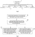
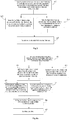
- An embodiment of the disclosure provides an encoding method, as shown in Fig. 4a , the method may be applied in the environment as shown in Fig. 1 , and the method includes: step 401, encoding 8-bit data corresponding to a to-be-encoded byte of to-be-transmitted data into 9-bit data, the to-be-transmitted data comprising at least one to-be-encoded byte; and then performing step 402 or step 405 according to the situation.
- the to-be-transmitted data Before data transmission, it is necessary to encode to-be-transmitted data, the to-be-transmitted data includes at least one to-be-encoded byte, and each to-be-encoded byte is 8-bit data. It is noted that, in an embodiment of the disclosure, at a sending end of data, the bit digits of the data are arranged in an order from low digit to high digit. For example, the arrangement order of data 10000010 is from right to left, that is, its first digit of data is 0, its last digit of data is 1, "1000" is its 4 high digits, and "0010" is its 4 low digits.
- a procedure of encoding 8-bit data corresponding to a to-be-encoded byte of to-be-transmitted data into 9-bit data includes:
- ( ⁇ d[2]& ⁇ d[0]) ( ⁇ 0&1)
- ( ⁇ 0& ⁇ 0) (1&1)
- (1&1) 1
- the first digit of data of the 9-bit data and a previous digit of data adjacent to the first digit of data are detected, when the to-be-encoded byte is not the first byte of the to-be-transmitted data.
- the to-be-transmitted data may include multiple bytes, and the encoding approach may be different for situations in which the to-be-encoded byte is the first byte and is not the first byte, at the time of encoding, it may be possible to first detect whether the to-be-encoded byte is the first byte of the to-be-transmitted data, and if no, since the data is encoded in order, it shows that there exist at least one encoded byte in front of the to-be-encoded byte, that is, byte(s) for which the 8b/10b encoding has been done.
- step 403 may be performed, and if they are different, step 404 may be performed.
- the 9-bit data is inverted and then a tenth digit of data for indicating that the inverted 9-bit data has undergone an inversion operation is added behind the inverted 9-bit data to obtain 10-bit data, when the numerical value of the first digit of data is the same as that of the previous digit of data
- adopting a tenth digit of data to indicate whether the 9-bit data has undergone an inversion operation may ensure that the receiving end can effectively decode the received data.
- the tenth digit of data when the tenth digit of data is 1, it indicates that the 9-bit data has undergone an inversion operation, and when the tenth digit of data is 0, it indicates that the 9-bit data has not undergone an inversion operation. Then, when the numerical value of the first digit of data is the same as that of the previous digit of data (e.g., both the first digit of data and the previous digit of data are 0, or both the first digit of data and the previous digit of data are 1), the 9-bit data is inverted and then a tenth digit of data, i.e. 1, for indicating that the inverted 9-bit data has undergone an inversion operation is added behind the inverted 9-bit data to obtain 10-bit data.
- the numerical value of the first digit of data is the same as that of the previous digit of data (e.g., both the first digit of data and the previous digit of data are 0, or both the first digit of data and the previous digit of data are 1)
- the to-be-encoded 9-bit data is 100100010
- 10-bit data located ahead of and adjacent to the 9-bit data is 0101000100. Since the first digit of data of the 9-bit data is 0, the last digit of its previous 10-bit data is 0 (that is, a previous digit of data to the first digit of data is 0), and the two are the same, the 9-bit data is inverted to obtain 011011101, then a tenth digit of data 1 is added, and the finally obtained 10-bit data is 1011011101.
- Step 404 a tenth digit of data for indicating that the 9-bit data has not undergone an inversion operation is added behind the 9-bit data to obtain 10-bit data, when the numerical value of the first digit of data is different from that of the previous digit of data. Step 406 is performed.
- a procedure of adding a tenth digit of data for indicating that the 9-bit data has not undergone an inversion operation behind the 9-bit data to obtain 10-bit data when the numerical value of the first digit of data is different from that of the previous digit of data may specifically include: adding a tenth digit of data for indicating that the 9-bit data has not undergone an inversion operation and being 0 behind the 9-bit data to obtain 10-bit data when one of the first digit of data and the previous digit of data is 0 and the other is 1.
- the to-be-encoded 9-bit data is 100100010
- 10-bit data located ahead of and adjacent to the 9-bit data is 1100100100. Since the first digit of data of the 9-bit data is 0, the last digit of its previous 10-bit data is 1 (that is, a previous digit of data to the first digit of data is 1), and the two are different, a tenth digit of data 0 is added behind the 9-bit data, and the finally obtained 10-bit data is 0100100010.
- the above steps 403 and 404 may ensure that a jumping edge exists between every two adjacent encoded bytes (that is, every two 10-bit data), and this facilitates the receiving end to clearly differentiate between every two adjacent encoded bytes and implement accurate decoding.
- the to-be-encoded byte is the first byte of the to-be-transmitted data
- assume the previous digit of data to the first digit of data of the 9-bit data is 0, and the 9-bit data is processed according to the step 403 or the step 404, to obtain 10-bit data.
- the previous digit of data to the first digit of data of the 9-bit data does not exist. It is assumed in the embodiment of the disclosure that the previous digit of data is 0, and in other embodiments, it may also be assumed that the previous digit of data to its first digit of data is 1, and then the steps 403 to 404 are performed.
- the to-be-encoded byte is the first byte of the to-be-transmitted data
- the to-be-encoded byte is the first byte of the to-be-transmitted data, that is, a previous digit of data does not exist in front of its first digit of data
- a jumping edge exists between the first digit of data of the 9-bit data and the previous digit of data
- a tenth digit of data for indicating that the 9-bit data has not undergone an inversion operation is added behind the 9-bit data to obtain 10-bit data, of which a specific procedure may be referred to the step 404.
- a jumping edge does not exist between the first digit of data of the 9-bit data and the previous digit of data, and it may be possible to invert the 9-bit data and then add a tenth digit of data for indicating that the inverted 9-bit data has undergone an inversion operation is added behind the inverted 9-bit data to obtain 10-bit data, of which a specific procedure may be referred to the step 403.
- a first identification code is added at a preset position of the encoded to-be-transmitted data to obtain target data.
- the encoded to-be-transmitted data includes 10-bit data obtained by encoding the 8-bit data corresponding to the to-be-encoded byte.
- the sending end also needs to send data in one unit per 10 bits, and therefore, the first identification code needs to be 10-bit data and may be preset data, as long as it plays the role of identification.
- the 8b/9b encoding algorithm provided by the step 401 may ensure that at least one of any 5 consecutive digits of the 9-bit data is different from the other digits, and after the 9b/10b encoding algorithm of the steps 403-405, since a tenth digit of data is added, it may be ensured that at least one of any 6 consecutive digits of the 10-bit data is different from the other digits, that is, 6 consecutive 0s or 6 consecutive Is will not appear in the 10-bit data obtained by the encoding.
- the first identification code may include at least 6 consecutive digits of identical data to be differentiated from normally transmitted 10-bit data.
- the first identification code may include 6 consecutive 0s or 6 consecutive Is.
- the first identification code is used for identifying transmitted content, start of transmission or end of transmission.
- the first identification code may be denoted as K, and its specific code value may be referred to table 1.
- Table 1 K1 0b0111111010 0b1000000101 K2 0b0111111011 0b1000000100 K3 0b0111111001 0b1000000110 K4 0b0111111000 0b1000000111
- each identification code in K1 to K4 corresponds to two representations, respectively, and its first digit of data (note that it means the first of the low digits on the right side) is determined according to a previous digit of data to guarantee forming a flip edge with the previous digit of data.
- the K1 code is adopted of which the first digit of data is 1, that is, 1000000101
- the K1 code is adopted of which the first digit of data is 0, that is, 0111111010, which may thus guarantee effective recognition of the first identification code.
- K1 is used for indicating start of transmission
- K2 is used for indicating cutoff of transmission
- K3 is used for indicating a cutoff position of a row signal and may further be used for instructing a linear feedback register to perform a reset operation
- K4 is used for indicating end of transmission.
- the first identification code when used for indicating start of transmission, the first identification code may be directly added in front of the to-be-transmitted data, or may also be added in front of the to-be-transmitted data in the form of combined code. Exemplarily, as shown in Fig.
- a procedure of adding the first identification code in front of the encoded to-be-transmitted data to obtain target data may include: step 4061, splicing the first identification code and a second identification code into a combined code, the second identification code being also preset 10-bit data, the second identification code also comprising at least 6 consecutive digits of identical data, and the second identification code being different from the first identification code.
- the combined code may include at least one first identification code and at least one second identification code, and the numerical value of a first identification code at a different position in the same combined code may be different.
- the first identification codes in the combined code include different K1 in table 1.
- the numerical value of a second identification code at a different position may be different.
- the sending end and the receiving end may pre-agree on an arrangement way of a combined code, and employ a form of a combined code table for record.
- the receiving end may recover the correct combined code by querying the combined code table.
- a first identification code is K1
- a second identification code is G1
- a combined code may be K1G1G1K1
- the receiving end may recover K1G1G1K1 by looking up the table according G1.
- the second identification code is denoted as G, and G may have 4 forms in total, G1, G2, G3 and G4, of which specific code values may be referred to table 2, wherein 0b represents binary.
- Table 2 G1 0b0101010111 0b10101000 G2 0b0100011111 0b1011100000 G3 0b0110001111 0b1001110000 G4 0b0111000111 0b1000111000
- a combined code is obtained by combining a first identification code K and a second identification code G in the form of KGKG
- the combined code table may be referred to table 3.
- the received combined code is successively arranged 0111111010, 1010101000, 1000000101 and 1111111111.
- the first 3 10-bit data of the combined code is identical to the first 3 10-bit data in the combined code of the first row in table 3, and therefore, it may be determined that the correct combined code is successively arranged 0111111010, 1010101000, 1000000101 and 0101010111, and accordingly, the first identification code that may be extracted is K1.
- the combined code is added at a preset position of the encoded to-be-transmitted data to obtain the target data.
- the preset position is determined according to the content indicated by the first identification code. For example, when the first identification code indicates start of transmission, the preset position is a position in front of the to-be-transmitted data, that is, in front of the first digit of data of the first set of 10-bit data; when the first identification code indicates end of transmission, the preset position is a position behind the to-be-transmitted data, that is, behind the last digit of data of the last set of 10-bit data of the to-be-transmitted data; and when the first identification code is used for identifying transmitted content, the preset position may be between two specified sets of 10-bit data of the to-be-transmitted data.
- the target data is sent.
- the receiving end of data when the sending end of data is a timing controller, the receiving end of data may be a source driver chip, and when the sending end of data is a source driver chip, the receiving end of data may be a timing controller.
- the timing controller may send the target data to a corresponding source driver chip via a first signal line (e.g., a high speed differential signal line) or the second signal line, which will not be limited by the embodiment of the disclosure.
- 8-bit data is encoded into 9-bit data first, and then a tenth digit is added to obtain 10-bit data; and a jumping edge is arranged between every two adjacent 10-bit data, and the tenth digit of data is used for indicating whether the 9-bit data has undergone an inversion operation, which can effectively ensure that the to-be-transmitted data can be correctly recovered at a receiving end, and the jumping edge may effectively reduce transmission errors.
- An embodiment of the disclosure provides a decoding method which corresponds to the encoding method provided by the embodiment of the disclosure. As shown in Fig. 5a , the method may be applied in the environment as shown in Fig. 1 , and the method includes the following steps.
- step 501 target data is received.
- the target data includes at least one set of 10-bit data, which is binary data.
- the target data generally includes at least two sets of 10-bit data, wherein a first identification code may be included, and the first identification code may identify transmitted content, start of transmission or end of transmission, to facilitate better recognition of to-be-decoded data.
- the receiving end of data when the sending end of data is a timing controller, the receiving end of data may be a source driver chip, and when the sending end of data is a source driver chip, the receiving end of data may be a timing controller.
- the source driver chip may send the target data to a corresponding timing controller via a first signal line (e.g., a high speed differential signal line) or the second signal line, which will not be limited by embodiments of the disclosure.
- a first identification code is determined according to the combined code, and to-be-decoded data is determined according to the first identification code.
- the combined code is obtained by splicing the first identification code and a second identification code;
- the first identification code is preset 10-bit data, and the first identification code includes at least 6 consecutive digits of identical data;
- the second identification code is also preset 10-bit data, and the second identification code also includes at least 6 consecutive digits of identical data; and the second identification code is different from the first identification code.
- the combined code may include at least one first identification code and at least one second identification code, and the numerical value of a first identification code at a different position in the same combined code may be different.
- the first identification codes in the combined code include different K1 in table 1.
- the numerical value of a second identification code at a different position may be different.
- the sending end and the receiving end may pre-agree on an arrangement way of a combined code, and employ a form of a combined code table for record.
- the receiving end may recover the correct combined code by querying the combined code table.
- the receiving end may determine a first identification code according to the combined code, and then determine to-be-decoded data according to the first identification code.
- the receiving end may query a combined code table according to the combined code, and when there is at least one identification code in the combined code which may be queried in the combined code table, which shows there is at least one identification code transmitted correctly in the combined code, the correct combined code may be recovered by querying the table, and then a first identification code is extracted from a preset position of the combined code, to determine to-be-decoded data.
- the position of a specific first identification code in the target data is determined according to the first identification code, and then the to-be-decoded data is determined according to the first identification code and its position.
- the first identification code is carried in the form of a combined code, which may improve the accuracy of decoding the first identification code.
- to-be-decoded data is determined according to the first identification code.
- the to-be-decoded data includes at least one set of to-be-decoded 10-bit data, the first identification code is preset 10-bit data, and the first identification code includes at least 6 consecutive digits of identical data.
- a first identification code is used for identifying transmitted content, start of transmission or end of transmission, it may be possible to determine the position of a specific first identification code in the target data according to the first identification code, and then determine the to-be-decoded data according to the first identification code and its position.
- the tenth digit of data of the to-be-decoded 10-bit data is detected, the tenth digit of data being used for indicating whether the first 9 bits of data in the to-be-decoded 10-bit data have undergone an inversion operation.
- the first 9 bits of data are inverted to obtain pre-decoded 9-bit data, when the tenth digit of data indicates that the first 9 bits of data have undergone an inversion operation.
- the tenth digit of data when the tenth digit of data is 1, it may indicate that the 9 bits of data have undergone an inversion operation, and when the tenth digit of data is 0, it may indicate that the 9 bits of data have not undergone an inversion operation.
- the to-be-decoded 10-bit data is 1011011101. Its tenth digit of data is 1, showing that the first 9 bits of data 011011101 have undergone an inversion operation, and the first 9 bits of data 011011101 are inverted to obtain pre-decoded 9-bit data 100100010.
- the first 9 bits of data are taken as pre-decoded 9-bit data, when the tenth digit of data indicates that the first 9 bits of data have not undergone an inversion operation.
- the tenth digit of data when the tenth digit of data is 1, it may indicate that the 9 bits of data have undergone an inversion operation, and when the tenth digit of data is 0, it may indicate that the 9 bits of data have not undergone an inversion operation.
- the to-be-decoded 10-bit data is 0011011101. Its tenth digit of data is 0, showing that the first 9 bits of data 011011101 have not undergone an inversion operation, and the first 9 bits of data 011011101 are taken as pre-decoded 9-bit data 011011101.
- the pre-decoded 9-bit data is decoded into 8-bit data.
- Decoding the pre-decoded 9-bit data into 8-bit data includes decoding the pre-decoded 9-bit data into the 8-bit data as follows:
- the 10-bit data is decoded into 9-bit data according to the tenth digit of data first, and then the 9-bit data is decoded into 8-bit data, which can effectively ensure that the transmitted data can be correctly recovered at a receiving end, and the jumping edge may effectively reduce transmission errors.
- the above described encoding method may effectively reduce the probability of incorrect transmission, such that the receiving end can support the clock transmission approaches of the PLL and the DLL simultaneously by the above decoding approach.
- An embodiment of the disclosure provides an encoding device, as shown in Fig. 6a , comprising: an encoder 601 for performing the step 401 in Fig. 4a , namely, encoding 8-bit data corresponding to a to-be-encoded byte of to-be-transmitted data into 9-bit data, the to-be-transmitted data comprising at least one to-be-encoded byte; a detector 602 for performing the step 402 in Fig.
- the encoder when performing data encoding, encodes 8-bit data into 9-bit data first, then adds a tenth digit to obtain 10-bit data, and arranges a jumping edge between every two adjacent 10-bit data, and the tenth digit of data is used for indicating whether the 9-bit data has undergone an inversion operation, which can effectively ensure that the to-be-transmitted data can be correctly recovered at a receiving end, and the jumping edge may effectively reduce transmission errors.
- At least one of any 5 consecutive digits of the 9-bit data is different from the other digits, and the encoder 601 is specifically used for encoding the 8-bit data into the 9-bit data as follows:
- the tenth digit of data when the tenth digit of data is 1, it indicates that the 9-bit data has undergone an inversion operation, and when the tenth digit of data is 0, it indicates that the 9-bit data has not undergone an inversion operation.
- the encoder 601 is specifically used for, inverting the 9-bit data and then adding a tenth digit of data for indicating that the inverted 9-bit data has undergone an inversion operation and being 1 behind the inverted 9-bit data to obtain 10-bit data, when both the first digit of data and the previous digit of data are 0 or both the first digit of data and the previous digit of data are 1; and adding a tenth digit of data for indicating that the 9-bit data has not undergone an inversion operation and being 0 behind the 9-bit data to obtain 10-bit data, when one of the first digit of data and the previous digit of data is 0 and the other is 1.
- the encoder 601 is further used for implementing the step 405 in Fig. 4b and in turn proceeding to the step 403 or 403, namely, detecting whether the first digit of data of the 9-bit data is 0 when the to-be-encoded byte is the first byte of the to-be-transmitted data; inverting the 9-bit data and then adding a tenth digit of data for indicating that the inverted 9-bit data has undergone an inversion operation behind the inverted 9-bit data to obtain 10-bit data, when the first digit of data is 0; and adding a tenth digit of data for indicating that the 9-bit data has not undergone an inversion operation behind the 9-bit data to obtain 10-bit data, when the first digit of data is not 0.
- the device further includes: a processor 603 for performing the step 406 in Fig. 4a , namely, adding a first identification code at a preset position of the encoded to-be-transmitted data to obtain target data, the first identification code being preset 10-bit data, the first identification code comprising at least 6 consecutive digits of identical data, the first identification code being used for identifying transmitted content, start of transmission or end of transmission, and the encoded to-be-transmitted data comprising the 10-bit data obtained by encoding the 8-bit data corresponding to the to-be-encoded byte; and a sender 604 for sending the target data.
- a processor 603 for performing the step 406 in Fig. 4a , namely, adding a first identification code at a preset position of the encoded to-be-transmitted data to obtain target data, the first identification code being preset 10-bit data, the first identification code comprising at least 6 consecutive digits of identical data, the first identification code being used for identifying transmitted content, start of transmission or end
- the processor 603 is specifically used for performing the step 4061 in Fig. 4e , namely, splicing the first identification code and a second identification code into a combined code, the second identification code being also preset 10-bit data, the second identification code also comprising at least 6 consecutive digits of identical data, and the second identification code being different from the first identification code; and the step 4062, namely, adding the combined code at a preset position of the encoded to-be-transmitted data to obtain the target data.
- the encoder when performing data encoding, encodes 8-bit data into 9-bit data first, then adding a tenth digit to obtain 10-bit data, and arranging a jumping edge between every two adjacent 10-bit data, and the tenth digit of data is used for indicating whether the 9-bit data has undergone an inversion operation, which can effectively ensure that the to-be-transmitted data can be correctly recovered at a receiving end, and the jumping edge may effectively reduce transmission errors.
- An embodiment of the disclosure provides a decoding device corresponding to the encoding device as shown in Fig. 6a , as shown in Fig. 7a , comprising: a detector 701 for performing the step 504 in Fig. 5a , namely, detecting the tenth digit of data of to-be-decoded 10-bit data, the tenth digit of data being used for indicating whether the first 9 bits of data in the to-be-decoded 10-bit data have undergone an inversion operation; and a decoder 702 for performing the steps 505 or 506 and 508 in Fig.
- the decoder when performing data decoding, decodes the 10-bit data into 9-bit data according to the tenth digit of data first, and then decodes the 9-bit data into 8-bit data, which can effectively ensure that the transmitted data can be correctly recovered at a receiving end, and the jumping edge may effectively reduce transmission errors.
- the decoder 702 is specifically used for decoding the pre-decoded 9-bit data into the 8-bit data as follows:
- the tenth digit of data when the tenth digit of data is 1, it indicates that the 9-bit data has undergone an inversion operation, and when the tenth digit of data is 0, it indicates that the 9-bit data has not undergone an inversion operation.
- the device further includes: a receiver 703 for receiving target data; and a processor 704 for performing the step 502 in Fig. 5a , namely, determining to-be-decoded data according to a first identification code when it is detected that the target data includes the first identification code, the to-be-decoded data comprising at least one set of to-be-decoded 10-bit data, the first identification code being preset 10-bit data, the first identification code comprising at least 6 consecutive digits of identical data, and the first identification code being used for identifying transmitted content, start of transmission or end of transmission.
- the processor 704 is further used for performing the step 503 in Fig. 5a , namely, determining a first identification code according to a combined code when it is detected that the target data includes the combined code, and determining to-be-decoded data according to the first identification code; wherein the combined code is obtained by splicing the first identification code and the second identification code, the second identification code is also preset 10-bit data, the second identification code also includes at least 6 consecutive digits of identical data, and the second identification code is different from the first identification code.
- the decoder when performing data decoding, decodes the 10-bit data into 9-bit data according to the tenth digit of data first, and then decodes the 9-bit data into 8-bit data, which can effectively ensure that the transmitted data can be correctly recovered at a receiving end, and the jumping edge may effectively reduce transmission errors.
- an embodiment of the disclosure provides a signal transmission system 80 comprising a timing controller and a source driver chip.
- a structure of the signal transmission system may be referred to Fig. 1 , wherein the timing controller may include an encoding device 801 which may be an encoding device as shown in Fig. 6a or Fig. 6b , and the source driver chip may include a decoding device 802 which may be a decoding device as shown in Fig. 7a or Fig. 7b .
- an embodiment of the invention provides a signal transmission system 80 comprising a timing controller and a source driver chip.
- a structure of the signal transmission system may be referred to Fig. 1 , wherein the timing controller may include a decoding device 802 which may be a decoding device as shown in Fig. 7a or Fig. 7b , and the source driver chip may include an encoding device 801 which may be an encoding device as shown in Fig. 6a or Fig. 6b .
- the encoding device 801 may perform 8b/10b encoding, and the decoding device 802 may perform 10b/8b decoding.
- the encoding device 801 first performs 8b/9b processing to output 9-bit data, then adds a tenth bit digit for indicating whether preceding 9-bit data has undergone inversion processing, and finally outputs 10-bit data; and after receive a first identification code, the decoding device 802 determines to-be-decoded data according to the first identification code, then determines a tenth digit of data in the to-be-decoded data, determines pre-decoded 9-bit data according to the tenth digit of data, and then performs 9b/8b processing to output 8-bit data.
- the encoding and decoding procedure may be referred to the embodiments of the methods as described above, which will not be repeated by an embodiment of the disclosure.
- the signal transmission system may be applied in a display device, which may be any product or component with the display function, such as a liquid crystal panel, an electronic paper, an organic light emitting diode (OLED for short) panel, a mobile phone, a tablet computer, a television, a display, a notebook computer, a digital photo frame, a navigator, etc.
- a display device which may be any product or component with the display function, such as a liquid crystal panel, an electronic paper, an organic light emitting diode (OLED for short) panel, a mobile phone, a tablet computer, a television, a display, a notebook computer, a digital photo frame, a navigator, etc.
- the encoding and decoding method used by it at the time of data encoding, 8-bit data is encoded into 9-bit data first, then a tenth digit is added to obtain 10-bit data, a jumping edge is arranged between every two adjacent 10-bit data, and the tenth digit of data is used for indicating whether the 9-bit data has undergone an inversion operation, which can effectively ensure that the to-be-transmitted data can be correctly recovered at a receiving end, and the jumping edge may effectively reduce transmission errors; and at the time of data decoding, the 10-bit data is decoded into 9-bit data according to the tenth digit of data first, and then the 9-bit data is decoded into 8-bit data, which can effectively ensure that the transmitted data can be correctly recovered at a receiving end, and the jumping edge may effectively reduce transmission errors; and the logic of the encoding and decoding is simple, fewer resources are occupied, and the achievability is high.
Landscapes
- Engineering & Computer Science (AREA)
- Theoretical Computer Science (AREA)
- Physics & Mathematics (AREA)
- Computer Hardware Design (AREA)
- General Physics & Mathematics (AREA)
- Chemical & Material Sciences (AREA)
- Crystallography & Structural Chemistry (AREA)
- Spectroscopy & Molecular Physics (AREA)
- Computer Networks & Wireless Communication (AREA)
- Signal Processing (AREA)
- Dc Digital Transmission (AREA)
- Compression, Expansion, Code Conversion, And Decoders (AREA)
Abstract
Description
- This application claims the priority of the Chinese patent application with the filing date of June 9, 2017 and the application number of
201710434609.3 - This application relates to the field of panel manufacturing, and in particular, to an encoding method and device, a decoding method and device, and a signal transmission system.
- A driving part of a liquid crystal display panel generally includes a timing controller, a source driver and a gate driver, wherein the main function of the timing controller is to process each frame of image data to generate a data signal and a control signal corresponding to each frame of image data, the data signal is communicated to the source driver, and the source driver converts the received data signal into a data voltage to be written to a corresponding pixel on the liquid crystal display panel.
- With the increase of the resolution of the liquid crystal display panel, the rate of data transmission between the timing controller and the source driver in the liquid crystal display panel is higher and higher, and nowadays, there is an 8b/10b (i.e., encoding 8-bit data into 10-bit data) encoding method for high speed data transmission. In particular, 8-bit original data is divided into two parts, 5b/6b (i.e., encoding 5-bit data into 6-bit data) encoding is performed on the first 5 digits thereof, and 3b/4b (i.e., encoding 3-bit data into 4-bit data) encoding is performed on the last 3 digits thereof.
- However, with the development of codec technology, in the current field of timing control, there are usually two approaches for signal transmission, Phase Locked Loop (PLL for short) and Delay-locked Loop (DLL for short), wherein the PLL is more common, and the DLL requires that a jumping edge needs to occur in a transmission procedure. However, the above-mentioned encoding method only supports the PLL transmission approach and not the DLL transmission approach.
- To solve the problem that the existing 8b/10b encoding method cannot support the PLL and the DLL simultaneously, embodiments of this application provide an encoding method and device, a decoding method and device, and a signal transmission system. The technical solutions are as follows.
- In a first aspect, there is provided an encoding method comprising: encoding 8-bit data corresponding to a to-be-encoded byte of to-be-transmitted data into 9-bit data, the to-be-transmitted data comprising at least one to-be-encoded byte; detecting the first digit of data of the 9-bit data and a previous digit of data adjacent to the first digit of data, when the to-be-encoded byte is not the first byte of the to-be-transmitted data; inverting the 9-bit data and then adding a tenth digit of data for indicating that the inverted 9-bit data has undergone an inversion operation behind the inverted 9-bit data to obtain 10-bit data, when the numerical value of the first digit of data is the same as that of the previous digit of data; and adding a tenth digit of data for indicating that the 9-bit data has not undergone an inversion operation behind the 9-bit data to obtain 10-bit data, when the numerical value of the first digit of data is different from that of the previous digit of data; wherein all the said data is binary data.
- In an embodiment, at least one of any 5 consecutive digits of the 9-bit data is different from the other digits, and the encoding 8-bit data corresponding to a to-be-encoded byte of to-be-transmitted data into 9-bit data includes encoding the 8-bit data into the 9-bit data as follows:
- enc[0]=d[3];
- enc[1]=(∼d[2]&d[1])|(d[2]&d[1]&∼d[3])|(∼d[2]&∼d[0]);
- enc[2]=(d[2]&∼d[1])|(d[2]&d[1]&∼d[3])|(∼d[1]&d[0]);
- enc[3]=d[5];
- enc[4]=d[6];
- enc[5]=(∼d[2]&∼d[1]&∼d[4])|(d[2]&∼d[0])|(d[1]&∼d[0]);
- enc[6]=(∼d[2]&∼d[1]&∼d[4])|(d[2]&d[0])|(d[1]&d[0]);
- enc[7]=d[4];
- enc[8]=d[7];
- In an embodiment, when the tenth digit of data is 1, it indicates that the 9-bit data has undergone an inversion operation, and when the tenth digit of data is 0, it indicates that the 9-bit data has not undergone an inversion operation.
- Accordingly, when the numerical value of the first digit of data is the same as that of the previous digit of data (e.g., both the first digit of data and the previous digit of data are 0, or both the first digit of data and the previous digit of data are 1), the 9-bit data is inverted and then a tenth digit of data (i.e., 1) for indicating that the inverted 9-bit data has undergone an inversion operation is added behind the inverted 9-bit data to obtain 10-bit data. When the numerical value of the first digit of data is different from that of the previous digit of data (e.g., one of the first digit of data and the previous digit of data is 0, and the other is 1), a tenth digit of data (i.e., 0) for indicating that the 9-bit data has not undergone an inversion operation is added behind the 9-bit data to obtain 10-bit data.
- In an embodiment, after the encoding 8-bit data corresponding to a to-be-encoded byte into 9-bit data, the method further includes: detecting whether the first digit of data of the 9-bit data is 0 when the to-be-encoded byte is the first byte of the to-be-transmitted data; inverting the 9-bit data and then adding a tenth digit of data for indicating that the inverted 9-bit data has undergone an inversion operation behind the inverted 9-bit data to obtain 10-bit data, when the first digit of data is 0; and adding a tenth digit of data for indicating that the 9-bit data has not undergone an inversion operation behind the 9-bit data to obtain 10-bit data, when the first digit of data is not 0.
- In an embodiment, the method further includes: adding a first identification code at a preset position of the encoded to-be-transmitted data to obtain target data, the first identification code being preset 10-bit data, the first identification code comprising at least 6 consecutive digits of identical data, the first identification code being used for identifying transmitted content, start of transmission or end of transmission, and the encoded to-be-transmitted data comprising the 10-bit data obtained by encoding the 8-bit data corresponding to the to-be-encoded byte; and sending the target data.
- In an embodiment, the first identification code and a second identification code are spliced into a combined code, the second identification code is also preset 10-bit data, the second identification code also includes at least 6 consecutive digits of identical data, but the second identification code is different from the first identification code; and the combined code is added at a preset position of the encoded to-be-transmitted data to obtain the target data.
- In a second aspect, there is provided a decoding method comprising: detecting the tenth digit of data of to-be-decoded 10-bit data, the tenth digit of data being used for indicating whether the first 9 bits of data in the to-be-decoded 10-bit data have undergone an inversion operation; inverting the first 9 bits of data to obtain pre-decoded 9-bit data, when the tenth digit of data indicates that the first 9 bits of data have undergone an inversion operation; taking the first 9 bits of data as pre-decoded 9-bit data, when the tenth digit of data indicates that the first 9 bits of data have not undergone an inversion operation; and decoding the pre-decoded 9-bit data into 8-bit data; wherein all the said data is binary data.
- In an embodiment, at least one of any 5 consecutive digits of the pre-decoded 9-bit data is different from the other digits, and the decoding the pre-decoded 9-bit data into 8-bit data includes decoding the pre-decoded 9-bit data into the 8-bit data as follows:
- Dout[7]=d_code[8];
- Dout[6]=d_code[4];
- Dout[5]=d_code[3];
- Dout[4]=d_code[7];
- Dout[3]=d_code[0];
- Dout[2]=(d_code[6]^d_code[5])&∼(∼d_code[2]&d_code[1]);
- Dout[1]=(d_code[6]^d_code[5])&∼(d_code[2]&∼d_code[1]);
- Dout[0]=(d_code[6]&∼d_code[5])(d_code[6]&d_code[5]&d_ code[2])|(∼d_code[6]&∼d_code[5]&d_code[2]);
- In an embodiment, when the tenth digit of data is 1, it indicates that the 9-bit data has undergone an inversion operation, and when the tenth digit of data is 0, it indicates that the 9-bit data has not undergone an inversion operation.
- In an embodiment, before the detecting the tenth digit of data of to-be-decoded 10-bit data, the method further includes:
- receiving target data; and
- determining to-be-decoded data according to a first identification code when it is detected that the target data includes the first identification code, the to-be-decoded data comprising at least one set of to-be-decoded 10-bit data, the first identification code being preset 10-bit data, the first identification code comprising at least 6 consecutive digits of identical data, and the first identification code being used for identifying transmitted content, start of transmission or end of transmission.
- In an embodiment, after the receiving target data, the method further includes:
- determining a first identification code according to a combined code when it is detected that the target data includes the combined code, and determining to-be-decoded data according to the first identification code;
- wherein the combined code is obtained by splicing the first identification code and the second identification code, the second identification code is also preset 10-bit data, the second identification code also includes at least 6 consecutive digits of identical data, and the second identification code is different from the first identification code.
- In a third aspect, there is provided an encoding device comprising: an encoder for encoding 8-bit data corresponding to a to-be-encoded byte of to-be-transmitted data into 9-bit data, the to-be-transmitted data comprising at least one to-be-encoded byte; a detector for detecting the first digit of data of the 9-bit data and a previous digit of data adjacent to the first digit of data, when the to-be-encoded byte is not the first byte of the to-be-transmitted data; the encoder being further used for: inverting the 9-bit data and then adding a tenth digit of data for indicating that the inverted 9-bit data has undergone an inversion operation behind the inverted 9-bit data to obtain 10-bit data, when the numerical value of the first digit of data is the same as that of the previous digit of data; and adding a tenth digit of data for indicating that the 9-bit data has not undergone an inversion operation behind the 9-bit data to obtain 10-bit data, when the numerical value of the first digit of data is different from that of the previous digit of data; wherein all of the 8-bit data, the 9-bit data and the 10-bit data is binary data.
- In an embodiment, the encoder is specifically used for encoding the 8-bit data into the 9-bit data as follows, such that at least one of any 5 consecutive digits of the 9-bit data is different from the other digits:
- enc[0]=d[3];
- enc[1]=(∼d[2]&d[1])|(d[2]&d[1]&∼d[3])(∼d[2]&∼d[0]);
- enc[2]=(d[2]&∼d[1])|(d[2]&d[1]&∼d[3])|(∼d[1]&d[0]);
- enc[3]=d[5];
- enc[4]=d[6];
- enc[5]=(∼d[2]&∼d[1]&∼d[4])|(d[2]&∼d[0])|(d[1]&∼d[0]);
- enc[6]=(∼d[2]&∼d[1]&∼d[4])|(d[2]&d[0])|(d[1]&d[0]);
- enc[7]=d[4];
- enc[8]=d[7];
- In an embodiment, when the tenth digit of data is 1, it indicates that the 9-bit data has undergone an inversion operation, and when the tenth digit of data is 0, it indicates that the 9-bit data has not undergone an inversion operation.
- Accordingly, when both the first digit of data and the previous digit of data are 0, or both the first digit of data and the previous digit of data are 1, the 9-bit data is inverted and then a tenth digit of data for indicating that the inverted 9-bit data has undergone an inversion operation and being 1 is added behind the inverted 9-bit data to obtain 10-bit data. When one of the first digit of data and the previous digit of data is 0, and the other is 1, a tenth digit of data for indicating that the 9-bit data has not undergone an inversion operation and being 0 is added behind the 9-bit data to obtain 10-bit data.
- In an embodiment, the encoder is further used for: detecting whether the first digit of data of the 9-bit data is 0 when the to-be-encoded byte is the first byte of the to-be-transmitted data; inverting the 9-bit data and then adding a tenth digit of data for indicating that the inverted 9-bit data has undergone an inversion operation behind the inverted 9-bit data to obtain 10-bit data, when the first digit of data is 0; and adding a tenth digit of data for indicating that the 9-bit data has not undergone an inversion operation behind the 9-bit data to obtain 10-bit data, when the first digit of data is not 0.
- In an embodiment, the device further includes: a processor for adding a first identification code at a preset position of the encoded to-be-transmitted data to obtain target data, the first identification code being preset 10-bit data, the first identification code comprising at least 6 consecutive digits of identical data, the first identification code being used for identifying transmitted content, start of transmission or end of transmission, and the encoded to-be-transmitted data comprising the 10-bit data obtained by encoding the 8-bit data corresponding to the to-be-encoded byte; and a sender for sending the target data.
- In an embodiment, the processor is specifically used for splicing the first identification code and a second identification code into a combined code, the second identification code being also preset 10-bit data, the second identification code also comprising at least 6 consecutive digits of identical data, and the second identification code being different from the first identification code; and adding the combined code at a preset position of the encoded to-be-transmitted data to obtain the target data.
- In a fourth aspect, there is provided a decoding device comprising: a detector for detecting the tenth digit of data of to-be-decoded 10-bit data, the tenth digit of data being used for indicating whether the first 9 bits of data in the to-be-decoded 10-bit data have undergone an inversion operation; and a decoder for: inverting the first 9 bits of data to obtain pre-decoded 9-bit data, when the tenth digit of data indicates that the first 9 bits of data have undergone an inversion operation; taking the first 9 bits of data as pre-decoded 9-bit data, when the tenth digit of data indicates that the first 9 bits of data have not undergone an inversion operation; and decoding the pre-decoded 9-bit data into 8-bit data; wherein all the said data is binary data.
- In an embodiment, at least one of any 5 consecutive digits of the pre-decoded 9-bit data is different from the other digits, and the decoder is specifically used for decoding the pre-decoded 9-bit data into the 8-bit data as follows:
- Dout[7]=d_code[8];
- Dout[6]=d_code[4];
- Dout[5]=d_code[3];
- Dout[4]=d_code[7];
- Dout[3]=d_code[0];
- Dout[2]=(d_code[6]^d_code[5])&∼(∼d_code[2]&d_code[1]);
- Dout[1]=(d_code[6]^d_code[5])&∼(d_code[2]&∼d_code[1]);
- Dout[0]=(d_code[6]&∼d_code[5])(d_code[6]&d_code[5]&d_ code[2])(∼d_code[6]&~d_code[5]&d_code[2]);
- In an embodiment, when the tenth digit of data is 1, it indicates that the 9-bit data has undergone an inversion operation, and when the tenth digit of data is 0, it indicates that the 9-bit data has not undergone an inversion operation.
- In an embodiment, the device further includes: a receiver for receiving target data; and a processor for determining to-be-decoded data according to a first identification code when it is detected that the target data includes the first identification code, the to-be-decoded data comprising at least one set of to-be-decoded 10-bit data, the first identification code being preset 10-bit data, the first identification code comprising at least 6 consecutive digits of identical data, and the first identification code being used for identifying transmitted content, start of transmission or end of transmission.
- In an embodiment, the processor is further used for determining a first identification code according to a combined code when it is detected that the target data includes the combined code, and determining to-be-decoded data according to the first identification code; wherein the combined code is obtained by splicing the first identification code and the second identification code, the second identification code is also preset 10-bit data, the second identification code also includes at least 6 consecutive digits of identical data, and the second identification code is different from the first identification code.
- In a fifth aspect, there is provided a signal transmission system comprising a timing controller and a source driver chip, the timing controller comprising any of the encoding devices as described in the third aspect, and the source driver chip comprising any of the decoding devices as described in the fourth aspect. Or, there is provided a signal transmission system comprising a timing controller and a source driver chip, the timing controller comprising any of the decoding devices as described in the third aspect, and the source driver chip comprising any of the encoding devices as described in the third aspect.
- For the encoding method and device, the decoding method and device, and the signal transmission system provided by the individual embodiments of the disclosure, at the time of data encoding, 8-bit data is encoded into 9-bit data first, and then a tenth digit is added to obtain 10-bit data; and a jumping edge is arranged between every two adjacent 10-bit data, and the tenth digit of data is used for indicating whether the 9-bit data has undergone an inversion operation, which can effectively ensure that the to-be-transmitted data can be correctly recovered at a receiving end, and the jumping edge may effectively reduce transmission errors. Moreover, the encoding approach as described above meets the requirements of the PLL and the DLL simultaneously, such that the receiving end can support the signal transmission approaches of the PLL and the DLL simultaneously.
- It will be appreciated that, the above general description and the following detailed description is just exemplary, and cannot limit this application.
- In order to more clearly illustrate the embodiments of this application, the appended drawings needing to be used in the description of the embodiments will be introduced briefly in the following. Obviously, the drawings in the following description are only some embodiments of this application, and for the person having ordinary skills in the art, other drawings may also be obtained according to these drawings under the premise of not paying out undue experimentation.
-
Fig. 1 is a schematic diagram of an application environment of an encoding method and a decoding method provided by an embodiment of the disclosure. -
Fig. 2 is a flow diagram of an encoding method shown according to an exemplary embodiment. -
Fig. 3 is a flow diagram of a decoding method shown according to an exemplary embodiment. -
Fig. 4a is a flow diagram of another encoding method shown according to an exemplary embodiment. -
Fig. 4b is a schematic diagram of an 8b/9b encoding approach shown according to an exemplary embodiment. -
Fig. 4c is a schematic diagram of a 9b/10b encoding approach shown according to an exemplary embodiment. -
Fig. 4d is a schematic diagram of another 9b/10b encoding approach shown according to an exemplary embodiment. -
Fig. 4e is a flow chart of a method for adding a first identification code shown according to an exemplary embodiment. -
Fig. 5a is a flow diagram of another encoding method shown according to an exemplary embodiment. -
Fig. 5b is a schematic diagram of a 9b/8b decoding approach shown according to an exemplary embodiment. -
Fig. 6a is a structural schematic diagram of an encoding device shown according to an exemplary embodiment. -
Fig. 6b is a structural schematic diagram of another encoding device shown according to an exemplary embodiment. -
Fig. 7a is a structural schematic diagram of a decoding device shown according to an exemplary embodiment. -
Fig. 7b is a structural schematic diagram of another decoding device shown according to an exemplary embodiment. -
Fig. 8 is a structural schematic diagram of a signal transmission system shown according to an exemplary embodiment. - The drawings herein are incorporated into the specification and constitute a part of the specification, show embodiments in accordance with this application, and are used for explaining the principle of this application along with the specification.
- To make the objects, technical solutions and advantages of this application clearer, in the following, this application will be further described in detail in conjunction with the drawings. Obviously, the described embodiments are just a part of embodiments of this application, and not all the embodiments. Based on the embodiments in this application, all the other embodiments obtained by the person having ordinary skills in the art under the premise of not paying out undue experimentation pertain to the scope protected by this application.
- Reference is made to
Fig. 1 , which is a schematic diagram of an application environment of an encoding method and a decoding method provided by an embodiment of the disclosure. As shown inFig. 1 , the encoding and decoding methods are applied in a display device, the display device includes atiming controller 01 and a plurality of source driver chips 02, a plurality of first signal lines H of thetiming controller 01 are connected with the plurality of source driver chips 02 in a one to one correspondence, the timing controller is also connected with a second signal line L, and the plurality of source driver chips 02 are connected in parallel and connected with the second signal line L. The signal transmission rate of a first signal line is less than that of the second signal line, the first signal line may be called a low speed signal line and is usually used for identifying a level state, and the second signal line may be called a high speed signal line and is usually used for transmitting a high speed differential signal. - In an embodiment of the disclosure, there is provided a new 8b/10b (i.e., encoding 8-bit data into 10-bit data) encoding method, wherein both the 8-bit data before the encoding and the 10-bit data after the encoding is binary data, data transmitted between the timing
controller 01 and asource driver chip 02 may be encoded by adopting the encoding method, and the data transmitted between the timingcontroller 01 and thesource driver chip 02 may be data transmitted in a first signal line, or may also be data transmitted in the second signal line, which will not be limited by the embodiment of the disclosure. - As shown in
Fig. 2, Fig. 2 is a flow diagram of an encoding method provided by one embodiment of the disclosure, which may be applied in the environment as shown inFig. 1 . The method includes:step 201, encoding 8-bit data corresponding to a to-be-encoded byte of to-be-transmitted data into 9-bit data, the to-be-transmitted data comprising at least one to-be-encoded byte;step 202, detecting the first digit of data of the 9-bit data and a previous digit of data adjacent to the first bit of data, when the to-be-encoded byte is not the first byte of the to-be-transmitted data;step 203, inverting the 9-bit data and then adding a tenth digit of data for indicating that the inverted 9-bit data has undergone an inversion operation behind the inverted 9-bit data to obtain 10-bit data, when the numerical value of the first digit of data is the same as that of the previous digit of data; and step 204, adding a tenth digit of data for indicating that the 9-bit data has not undergone an inversion operation behind the 9-bit data to obtain 10-bit data, when the numerical value of the first digit of data is different from that of the previous digit of data; wherein all the said data is binary data, and the tenth digit of data is used for indicating whether the 9-bit data has undergone an inversion operation. - For the encoding method provided by the one embodiment of the disclosure, at the time of data encoding, 8-bit data is encoded into 9-bit data first, and then a tenth digit is added to obtain 10-bit data; and a jumping edge is arranged between every two adjacent 10-bit data, and the tenth digit of data is used for indicating whether the 9-bit data has undergone an inversion operation, which can effectively ensure that the to-be-transmitted data can be correctly recovered at a receiving end, and the jumping edge may effectively reduce transmission errors. Moreover, the encoding approach as described above meets the requirements of the PLL and the DLL simultaneously, such that the receiving end can support the signal transmission approaches of the PLL and the DLL simultaneously.
- As shown in
Fig. 3, Fig. 3 is a flow diagram of a decoding method provided by one embodiment of the disclosure, which may be applied in the environment as shown inFig. 1 . The method includes:step 301, detecting the tenth digit of data of to-be-decoded 10-bit data, the tenth digit of data being used for indicating whether the first 9 bits of data in the to-be-decoded 10-bit data have undergone an inversion operation;step 302, inverting the first 9 bits of data to obtain pre-decoded 9-bit data, when the tenth digit of data indicates that the first 9 bits of data have undergone an inversion operation;step 303, taking the first 9 bits of data as pre-decoded 9-bit data, when the tenth digit of data indicates that the first 9 bits of data have not undergone an inversion operation; and step 304, decoding the pre-decoded 9-bit data into 8-bit data; wherein all the said data is binary data. - For the decoding method provided by the one embodiment of the disclosure, at the time of data decoding, the 10-bit data is decoded into 9-bit data according to the tenth digit of data first, and then the 9-bit data is decoded into 8-bit data, which can effectively ensure that the transmitted data can be correctly recovered at a receiving end, and the jumping edge may effectively reduce transmission errors. Moreover, the encoding approach as described above meets the requirements of the PLL and the DLL simultaneously, such that the receiving end can support the signal transmission approaches of the PLL and the DLL simultaneously.
- An embodiment of the disclosure provides an encoding method, as shown in
Fig. 4a , the method may be applied in the environment as shown inFig. 1 , and the method includes:step 401, encoding 8-bit data corresponding to a to-be-encoded byte of to-be-transmitted data into 9-bit data, the to-be-transmitted data comprising at least one to-be-encoded byte; and then performingstep 402 or step 405 according to the situation. - Before data transmission, it is necessary to encode to-be-transmitted data, the to-be-transmitted data includes at least one to-be-encoded byte, and each to-be-encoded byte is 8-bit data. It is noted that, in an embodiment of the disclosure, at a sending end of data, the bit digits of the data are arranged in an order from low digit to high digit. For example, the arrangement order of
data 10000010 is from right to left, that is, its first digit of data is 0, its last digit of data is 1, "1000" is its 4 high digits, and "0010" is its 4 low digits. - In particular, a procedure of encoding 8-bit data corresponding to a to-be-encoded byte of to-be-transmitted data into 9-bit data includes:
- encoding the 8-bit data into the 9-bit data as follows:
- enc[0]=d[3];
- enc[1]=(∼d[2]&d[1])|(d[2]&d[1]&∼d[3])|(∼d[2]&∼d[0]);
- enc[2]=(d[2]&∼d[1])|(d[2]&d[1]&∼d[3])|(∼d[1]&d[0]);
- enc[3]=d[5];
- enc[4]=d[6];
- enc[5]=(∼d[2]&∼d[1]&∼d[4])|(d[2]&∼d[0])|(d[1]&∼d[0]);
- enc[6]=(∼d[2]&∼d[1]&∼d[4])|(d[2]&d[0])|(d[1]&d[0]);
- enc[7]=d[4];
- enc[8]=d[7];
- Exemplarily, as shown in
Fig. 4b , assume that the to-be-encoded 8-bit data is 10000010, and its first digit of data to the eighth digit of data are successively 0, 1, 0, 0, 0, 0, 0, 1. Then, it may be encoded into 9-bit data 100100010 according to the above encoding approach, wherein in the 9-bit data,
the first digit of data enc[0]=d[3]=0;
the second digit of data enc[1] = (∼d[2]&d[1])|(d[2]&d[1]&∼d[3]) |(~d[2]&~d[0]) = (∼0&1)|(0&1&∼c0)|(∼0&∼0) = (1&1)|(0&1&1)|(1&1) = 1|0|1 = 1;
the third digit of data enc[2] = (d[2]&∼d[1])|(d[2]&d[1]&∼d[3])| (∼d[1]&d[0]) = (0&∼1)|(0&1&∼0)|(∼1&0) = (0&0)|(0&1&1)|(0&0) = 0|0|0 = 0;
the fourth digit of data enc[3]=d[5]=0;
the fifth digit of data enc[4]=d[6]=0;
the sixth digit of data enc[5] = (∼d[2]&∼d[1]&∼d[4])|(d[2]&∼d[0])| (d[1]&∼d[0]) = (∼0&∼1&∼0)|(0&∼0)|(1&∼0) = (1&0&1)|(0&1)|(1&1) = 0|0|1 =1;
the seventh digit of data enc[6] = (∼d[2]&∼d[1]&∼d[4])|(d[2]&d[0])| (d[1]&d[0]) = (∼0&∼1&∼0)|(0&0)|(1&0) = (1&0&1)|(0&0)|(1&0) = 0|0|0 = 0;
the eighth digit of data enc[7]=d[4]=0;
the ninth digit of data enc[8]=d[7]=1. - By the above encoding approach, it may be ensured that at least one of any 5 consecutive digits of 9-bit data is different from the other digits, that is, 5 consecutive 0s or 5 consecutive Is will not appear in the 9-bit data.
- At
step 402, the first digit of data of the 9-bit data and a previous digit of data adjacent to the first digit of data are detected, when the to-be-encoded byte is not the first byte of the to-be-transmitted data. - Since the to-be-transmitted data may include multiple bytes, and the encoding approach may be different for situations in which the to-be-encoded byte is the first byte and is not the first byte, at the time of encoding, it may be possible to first detect whether the to-be-encoded byte is the first byte of the to-be-transmitted data, and if no, since the data is encoded in order, it shows that there exist at least one encoded byte in front of the to-be-encoded byte, that is, byte(s) for which the 8b/10b encoding has been done. For a byte for which the 8b/10b encoding has been done, actually, original 8-bit digits of data have been converted into 10-bit digits of data, and therefore an encoded byte corresponds to 10-bit data. For the to-be-encoded 9-bit data, it may be possible to detect the first digit of data of the 9-bit data and a previous digit of data adjacent to the first digit of data (that is, the last digit of previous 10-bit data) so as to compare whether they are the same, to conduct addition of a tenth digit of data which is used for indicating whether the 9-bit data has undergone an inversion operation. If they are the same,
step 403 may be performed, and if they are different,step 404 may be performed. - At the
step 403, the 9-bit data is inverted and then a tenth digit of data for indicating that the inverted 9-bit data has undergone an inversion operation is added behind the inverted 9-bit data to obtain 10-bit data, when the numerical value of the first digit of data is the same as that of the previous digit of data - In an embodiment of the disclosure, adopting a tenth digit of data to indicate whether the 9-bit data has undergone an inversion operation may ensure that the receiving end can effectively decode the received data.
- Exemplarily, assume that when the tenth digit of data is 1, it indicates that the 9-bit data has undergone an inversion operation, and when the tenth digit of data is 0, it indicates that the 9-bit data has not undergone an inversion operation. Then, when the numerical value of the first digit of data is the same as that of the previous digit of data (e.g., both the first digit of data and the previous digit of data are 0, or both the first digit of data and the previous digit of data are 1), the 9-bit data is inverted and then a tenth digit of data, i.e. 1, for indicating that the inverted 9-bit data has undergone an inversion operation is added behind the inverted 9-bit data to obtain 10-bit data.
- Exemplarily, as shown in
Fig. 4c , assume that the to-be-encoded 9-bit data is 100100010, and 10-bit data located ahead of and adjacent to the 9-bit data is 0101000100. Since the first digit of data of the 9-bit data is 0, the last digit of its previous 10-bit data is 0 (that is, a previous digit of data to the first digit of data is 0), and the two are the same, the 9-bit data is inverted to obtain 011011101, then a tenth digit ofdata 1 is added, and the finally obtained 10-bit data is 1011011101. - At the
step 404, a tenth digit of data for indicating that the 9-bit data has not undergone an inversion operation is added behind the 9-bit data to obtain 10-bit data, when the numerical value of the first digit of data is different from that of the previous digit of data. Step 406 is performed. - Exemplarily, assume that when the tenth digit of data is 1, it indicates that the 9-bit data has undergone an inversion operation, and when the tenth digit of data is 0, it indicates that the 9-bit data has not undergone an inversion operation. Then, a procedure of adding a tenth digit of data for indicating that the 9-bit data has not undergone an inversion operation behind the 9-bit data to obtain 10-bit data when the numerical value of the first digit of data is different from that of the previous digit of data may specifically include: adding a tenth digit of data for indicating that the 9-bit data has not undergone an inversion operation and being 0 behind the 9-bit data to obtain 10-bit data when one of the first digit of data and the previous digit of data is 0 and the other is 1.
- Exemplarily, as shown in
Fig. 4d , assume that the to-be-encoded 9-bit data is 100100010, and 10-bit data located ahead of and adjacent to the 9-bit data is 1100100100. Since the first digit of data of the 9-bit data is 0, the last digit of its previous 10-bit data is 1 (that is, a previous digit of data to the first digit of data is 1), and the two are different, a tenth digit ofdata 0 is added behind the 9-bit data, and the finally obtained 10-bit data is 0100100010. - The
above steps - At the
step 405, when the to-be-encoded byte is the first byte of the to-be-transmitted data, assume the previous digit of data to the first digit of data of the 9-bit data is 0, and the 9-bit data is processed according to thestep 403 or thestep 404, to obtain 10-bit data. - In embodiments of the disclosure, since the to-be-encoded byte is the first byte of the to-be-transmitted data, the previous digit of data to the first digit of data of the 9-bit data does not exist. It is assumed in the embodiment of the disclosure that the previous digit of data is 0, and in other embodiments, it may also be assumed that the previous digit of data to its first digit of data is 1, and then the
steps 403 to 404 are performed. - In a practical application, when the to-be-encoded byte is the first byte of the to-be-transmitted data, it may further be possible to encode the 9-bit data into 10-bit data adopting other approaches, as long as it is ensured that the receiving end can effectively decode. For example, when the to-be-encoded byte is the first byte of the to-be-transmitted data, that is, a previous digit of data does not exist in front of its first digit of data, it may be assumed that a jumping edge exists between the first digit of data of the 9-bit data and the previous digit of data, and a tenth digit of data for indicating that the 9-bit data has not undergone an inversion operation is added behind the 9-bit data to obtain 10-bit data, of which a specific procedure may be referred to the
step 404. It may further be assumed that a jumping edge does not exist between the first digit of data of the 9-bit data and the previous digit of data, and it may be possible to invert the 9-bit data and then add a tenth digit of data for indicating that the inverted 9-bit data has undergone an inversion operation is added behind the inverted 9-bit data to obtain 10-bit data, of which a specific procedure may be referred to thestep 403. - At
step 406, a first identification code is added at a preset position of the encoded to-be-transmitted data to obtain target data. - The encoded to-be-transmitted data includes 10-bit data obtained by encoding the 8-bit data corresponding to the to-be-encoded byte. In an embodiment, to ensure that the receiving end receives data in one unit per 10 bits, the sending end also needs to send data in one unit per 10 bits, and therefore, the first identification code needs to be 10-bit data and may be preset data, as long as it plays the role of identification.
- In an embodiment of the disclosure, the 8b/9b encoding algorithm provided by the
step 401 may ensure that at least one of any 5 consecutive digits of the 9-bit data is different from the other digits, and after the 9b/10b encoding algorithm of the steps 403-405, since a tenth digit of data is added, it may be ensured that at least one of any 6 consecutive digits of the 10-bit data is different from the other digits, that is, 6 consecutive 0s or 6 consecutive Is will not appear in the 10-bit data obtained by the encoding. - Therefore, the first identification code may include at least 6 consecutive digits of identical data to be differentiated from normally transmitted 10-bit data. Exemplarily, the first identification code may include 6 consecutive 0s or 6 consecutive Is. The first identification code is used for identifying transmitted content, start of transmission or end of transmission.
- Exemplarily, the first identification code may be denoted as K, and its specific code value may be referred to table 1.
Table 1 K1 0b0111111010 0b1000000101 K2 0b0111111011 0b1000000100 K3 0b0111111001 0b1000000110 K4 0b0111111000 0b1000000111 - Therein, 0b represents binary, each identification code in K1 to K4 corresponds to two representations, respectively, and its first digit of data (note that it means the first of the low digits on the right side) is determined according to a previous digit of data to guarantee forming a flip edge with the previous digit of data. For example, when the previous digit of data to the first digit of data of the K1 code is 0, then the K1 code is adopted of which the first digit of data is 1, that is, 1000000101, and when the previous digit of data to the first digit of data of the K1 code is 1, then the K1 code is adopted of which the first digit of data is 0, that is, 0111111010, which may thus guarantee effective recognition of the first identification code. Exemplarily, in table 1, K1 is used for indicating start of transmission, K2 is used for indicating cutoff of transmission, K3 is used for indicating a cutoff position of a row signal and may further be used for instructing a linear feedback register to perform a reset operation, and K4 is used for indicating end of transmission.
- For example, when the first identification code is used for indicating start of transmission, the first identification code may be directly added in front of the to-be-transmitted data, or may also be added in front of the to-be-transmitted data in the form of combined code. Exemplarily, as shown in
Fig. 4e , when the first identification code is added in front of the to-be-transmitted data in the form of combined code, a procedure of adding the first identification code in front of the encoded to-be-transmitted data to obtain target data may include:step 4061, splicing the first identification code and a second identification code into a combined code, the second identification code being also preset 10-bit data, the second identification code also comprising at least 6 consecutive digits of identical data, and the second identification code being different from the first identification code. - In an embodiment of the disclosure, the combined code may include at least one first identification code and at least one second identification code, and the numerical value of a first identification code at a different position in the same combined code may be different. For example, the first identification codes in the combined code include different K1 in table 1. Similarly, the numerical value of a second identification code at a different position may be different. The sending end and the receiving end may pre-agree on an arrangement way of a combined code, and employ a form of a combined code table for record. In some embodiments, when there is at least one identification code in a combined code which is correctly transmitted, the receiving end may recover the correct combined code by querying the combined code table. For example, a first identification code is K1, a second identification code is G1, then a combined code may be K1G1G1K1, and when K1 is incorrectly transmitted, the receiving end may recover K1G1G1K1 by looking up the table according G1.
- Exemplarily, the second identification code is denoted as G, and G may have 4 forms in total, G1, G2, G3 and G4, of which specific code values may be referred to table 2, wherein 0b represents binary.
Table 2 G1 0b0101010111 0b1010101000 G2 0b0100011111 0b1011100000 G3 0b0110001111 0b1001110000 G4 0b0111000111 0b1000111000 - Exemplarily, assume that a combined code is obtained by combining a first identification code K and a second identification code G in the form of KGKG, and the combined code table may be referred to table 3. Assume that the received combined code is successively arranged 0111111010, 1010101000, 1000000101 and 1111111111. Employing the combined code to query the combined code table as shown in table 3, it may be found out that the first 3 10-bit data of the combined code is identical to the first 3 10-bit data in the combined code of the first row in table 3, and therefore, it may be determined that the correct combined code is successively arranged 0111111010, 1010101000, 1000000101 and 0101010111, and accordingly, the first identification code that may be extracted is K1.
Table 3 Combined code Extractable first identification code K G K G K1 0111111010 1010101000 1000000101 0101010111 K2 0111111011 1011100000 1000000100 0100011111 K3 0111111001 1001110000 1000000110 0110001111 K4 0111111000 1000111000 1000000111 0111000111 - At
step 4062, the combined code is added at a preset position of the encoded to-be-transmitted data to obtain the target data. - In an embodiment of the disclosure, the preset position is determined according to the content indicated by the first identification code. For example, when the first identification code indicates start of transmission, the preset position is a position in front of the to-be-transmitted data, that is, in front of the first digit of data of the first set of 10-bit data; when the first identification code indicates end of transmission, the preset position is a position behind the to-be-transmitted data, that is, behind the last digit of data of the last set of 10-bit data of the to-be-transmitted data; and when the first identification code is used for identifying transmitted content, the preset position may be between two specified sets of 10-bit data of the to-be-transmitted data.
- At
step 407, the target data is sent. - In an embodiment of the disclosure, when the sending end of data is a timing controller, the receiving end of data may be a source driver chip, and when the sending end of data is a source driver chip, the receiving end of data may be a timing controller. Exemplarily, the timing controller may send the target data to a corresponding source driver chip via a first signal line (e.g., a high speed differential signal line) or the second signal line, which will not be limited by the embodiment of the disclosure.
- It is noted that, the order of the steps of the encoding method provided by the embodiment of the disclosure may be appropriately adjusted, and the steps may also be increased or decreased accordingly according to the situation. Variations of the method easily occurring to any skilled person familiar with the technical field within the technical scope disclosed by the invention should all be encompassed within the protective scope of the invention, and therefore will not be repeated any longer.
- For the encoding method provided by an embodiment of the disclosure, at the time of data encoding, 8-bit data is encoded into 9-bit data first, and then a tenth digit is added to obtain 10-bit data; and a jumping edge is arranged between every two adjacent 10-bit data, and the tenth digit of data is used for indicating whether the 9-bit data has undergone an inversion operation, which can effectively ensure that the to-be-transmitted data can be correctly recovered at a receiving end, and the jumping edge may effectively reduce transmission errors.
- It is noted that, in the current field of timing control, there are usually two approaches for signal transmission, PLL and DLL, wherein the PLL is more common, and the DLL requires that a jumping edge needs to occur in a transmission procedure. However, since it can be ensured that a jumping edge occurs between two adjacent encoded bytes (that is, two adjacent sets of 10-bit data), the above described encoding method may effectively reduce the probability of incorrect transmission, and meet the requirements of the PLL and the DLL, such that the receiving end can support the signal transmission approaches of the PLL and the DLL simultaneously.
- In a practical application, the less the consecutive and identical data in the transmitted data, the better the jitter performance is. Since the 8b/9b encoding algorithm provided by the
step 401 may ensure that at least one of any 5 consecutive digits of the 9-bit data is different from the other digits, after the 9b/10b encoding algorithm of thesteps 403 to 405, it may be ensured that at least one of any 6 consecutive digits of the 10-bit data is different from the other digits, and therefore, it may be ensured that the encoded data will have a good jitter performance in a subsequent transmission procedure. - An embodiment of the disclosure provides a decoding method which corresponds to the encoding method provided by the embodiment of the disclosure. As shown in
Fig. 5a , the method may be applied in the environment as shown inFig. 1 , and the method includes the following steps. - At
step 501, target data is received. - The target data includes at least one set of 10-bit data, which is binary data. In an embodiment, the target data generally includes at least two sets of 10-bit data, wherein a first identification code may be included, and the first identification code may identify transmitted content, start of transmission or end of transmission, to facilitate better recognition of to-be-decoded data.
- In an embodiment of the disclosure, when the sending end of data is a timing controller, the receiving end of data may be a source driver chip, and when the sending end of data is a source driver chip, the receiving end of data may be a timing controller. Exemplarily, the source driver chip may send the target data to a corresponding timing controller via a first signal line (e.g., a high speed differential signal line) or the second signal line, which will not be limited by embodiments of the disclosure.
- At
step 502, when it is detected that the target data includes a combined code, a first identification code is determined according to the combined code, and to-be-decoded data is determined according to the first identification code. - In an embodiment of the disclosure, the combined code is obtained by splicing the first identification code and a second identification code; the first identification code is preset 10-bit data, and the first identification code includes at least 6 consecutive digits of identical data; the second identification code is also preset 10-bit data, and the second identification code also includes at least 6 consecutive digits of identical data; and the second identification code is different from the first identification code.
- The combined code may include at least one first identification code and at least one second identification code, and the numerical value of a first identification code at a different position in the same combined code may be different. For example, the first identification codes in the combined code include different K1 in table 1. Similarly, the numerical value of a second identification code at a different position may be different. The sending end and the receiving end may pre-agree on an arrangement way of a combined code, and employ a form of a combined code table for record. In some embodiments, when there is at least one identification code in a combined code which is correctly transmitted, the receiving end may recover the correct combined code by querying the combined code table.
- When it is detected that the target data includes a combined code, the receiving end may determine a first identification code according to the combined code, and then determine to-be-decoded data according to the first identification code. In particular, the receiving end may query a combined code table according to the combined code, and when there is at least one identification code in the combined code which may be queried in the combined code table, which shows there is at least one identification code transmitted correctly in the combined code, the correct combined code may be recovered by querying the table, and then a first identification code is extracted from a preset position of the combined code, to determine to-be-decoded data.
- It is noted that, when any of the identification codes in the combined code cannot be queried in the combined code table, it shows that the combined code is incorrect and the corresponding to-be-decoded data is also transmitted incorrectly, which may not be processed subsequently.
- Since the first identification is used for identifying transmitted content, start of transmission or end of transmission, the position of a specific first identification code in the target data is determined according to the first identification code, and then the to-be-decoded data is determined according to the first identification code and its position.
- In an embodiment of the disclosure, the first identification code is carried in the form of a combined code, which may improve the accuracy of decoding the first identification code.
- At
step 503, when it is detected that the target data includes a first identification code, to-be-decoded data is determined according to the first identification code. - The to-be-decoded data includes at least one set of to-be-decoded 10-bit data, the first identification code is preset 10-bit data, and the first identification code includes at least 6 consecutive digits of identical data.
- Since a first identification code is used for identifying transmitted content, start of transmission or end of transmission, it may be possible to determine the position of a specific first identification code in the target data according to the first identification code, and then determine the to-be-decoded data according to the first identification code and its position. Here, reference may be made to the relevant content at the
step 502. - At
step 504, the tenth digit of data of the to-be-decoded 10-bit data is detected, the tenth digit of data being used for indicating whether the first 9 bits of data in the to-be-decoded 10-bit data have undergone an inversion operation. - At
step 505, the first 9 bits of data are inverted to obtain pre-decoded 9-bit data, when the tenth digit of data indicates that the first 9 bits of data have undergone an inversion operation. - Exemplarily, assume that when the tenth digit of data is 1, it may indicate that the 9 bits of data have undergone an inversion operation, and when the tenth digit of data is 0, it may indicate that the 9 bits of data have not undergone an inversion operation. Assume that the to-be-decoded 10-bit data is 1011011101. Its tenth digit of data is 1, showing that the first 9 bits of data 011011101 have undergone an inversion operation, and the first 9 bits of data 011011101 are inverted to obtain pre-decoded 9-
bit data 100100010. - At
step 506, the first 9 bits of data are taken as pre-decoded 9-bit data, when the tenth digit of data indicates that the first 9 bits of data have not undergone an inversion operation. - Exemplarily, assume that when the tenth digit of data is 1, it may indicate that the 9 bits of data have undergone an inversion operation, and when the tenth digit of data is 0, it may indicate that the 9 bits of data have not undergone an inversion operation. Assume that the to-be-decoded 10-bit data is 0011011101. Its tenth digit of data is 0, showing that the first 9 bits of data 011011101 have not undergone an inversion operation, and the first 9 bits of data 011011101 are taken as pre-decoded 9-bit data 011011101.
- At
step 507, the pre-decoded 9-bit data is decoded into 8-bit data. - At least one of any 5 consecutive digits of the pre-decoded 9-bit data is different from the other digits, that is, 5 consecutive 0s or 5 consecutive Is will not appear in the 9-bit data. Decoding the pre-decoded 9-bit data into 8-bit data includes decoding the pre-decoded 9-bit data into the 8-bit data as follows:
- Dout[7]=d_code[8];
- Dout[6]=d_code[4];
- Dout[5]=d_code[3];
- Dout[4]=d_code[7];
- Dout[3]=d_code[0];
- Dout[2]=(d_code[6]^d_code[5])&∼(∼d_code[2]&d_code[1]);
- Dout[1]=(d_code[6]^d_code[5])&∼(d_code[2]&∼d_code[1]);
- Dout[0]=(d_code[6]&∼d_code[5])|(d_code[6]&d_code[5]&d_ code[2])|(∼d_code[6]&∼d_code[5]&d_code[2]);
- Exemplarily, as shown in
Fig. 5b , assume that the pre-decoded 9-bit data is 100100010, and its first digit of data to the ninth digit of data are successively 0, 1, 0, 0, 0, 1, 0, 0, 1. Then, it may be decoded into 8-bit data 10000010 according to the above decoding approach, wherein in the 8-bit data,
the eighth digit of data Dout[7]=d_code[8]=1;
the seventh digit of data Dout[6]=d_code[4]=0;
the sixth digit of data Dout[5]=d_code[3]=0;
the fifth digit of data Dout[4]=d_code[7]=0;
the fourth digit of data Dout[3]=d_code[0]=0;
the third digit of data Dout[2] = (d_code[6]^d_code[5])&~ (∼d_code[2]&d_code[1]) = (0^1)&∼(∼0&1) = 1&∼(1&1) = 1&∼1 = 1&0 =0;
the second digit of data Dout[1] = (d_code[6]^d_code[5])&∼ (d_code[2]&∼d_code[1]) = (0^1)&∼(0&∼1) = 1&∼(0&0) = 1&∼0 = 1&1 =1;
the first digit of data Dout[0] = (d_code[6]&∼d_code[5])|(d_code[6]& d_code[5]&d_code[2])|(∼d_code[6]&∼d_code[5]&d_code[2]) = (0&∼1)|(0&1&0)|(∼0&∼1&0) = (0&0)|(0&1&0)| (1&0&0) = 0|0|0 = 0. - For explanation of the first identifier, the second identifier, the combined identifier and other relevant features, reference may further be made to the description in connection with
Fig. 4a to Fig. 4e . - It is noted that, the order of the steps of the decoding method provided by the individual embodiments of the disclosure may be appropriately adjusted, and the steps may also be increased or decreased accordingly according to the situation. Variations of the method easily occurring to any skilled person familiar with the technical field within the technical scope disclosed by the invention should all be encompassed within the protective scope of the invention, and therefore will not be repeated any longer.
- For the decoding method provided by the individual embodiments of the disclosure, at the time of data decoding, the 10-bit data is decoded into 9-bit data according to the tenth digit of data first, and then the 9-bit data is decoded into 8-bit data, which can effectively ensure that the transmitted data can be correctly recovered at a receiving end, and the jumping edge may effectively reduce transmission errors.
- It is worth noting that since it can be ensured that a jumping edge occurs between two adjacent encoded bytes (that is, two adjacent sets of 10-bit data), the above described encoding method may effectively reduce the probability of incorrect transmission, such that the receiving end can support the clock transmission approaches of the PLL and the DLL simultaneously by the above decoding approach.
- An embodiment of the disclosure provides an encoding device, as shown in
Fig. 6a , comprising: anencoder 601 for performing thestep 401 inFig. 4a , namely, encoding 8-bit data corresponding to a to-be-encoded byte of to-be-transmitted data into 9-bit data, the to-be-transmitted data comprising at least one to-be-encoded byte; adetector 602 for performing thestep 402 inFig. 4a , namely, detecting the first digit of data of the 9-bit data and a previous digit of data adjacent to the first digit of data, when the to-be-encoded byte is not the first byte of the to-be-transmitted data; theencoder 601 being further used for performing thesteps Fig. 4a , namely, inverting the 9-bit data and then adding a tenth digit of data for indicating that the inverted 9-bit data has undergone an inversion operation behind the inverted 9-bit data to obtain 10-bit data, when the numerical value of the first digit of data is the same as that of the previous digit of data; and adding a tenth digit of data for indicating that the 9-bit data has not undergone an inversion operation behind the 9-bit data to obtain 10-bit data, when the numerical value of the first digit of data is different from that of the previous digit of data; wherein all the said data is binary data. - For the encoding device provided by the one embodiment of the disclosure, when performing data encoding, the encoder encodes 8-bit data into 9-bit data first, then adds a tenth digit to obtain 10-bit data, and arranges a jumping edge between every two adjacent 10-bit data, and the tenth digit of data is used for indicating whether the 9-bit data has undergone an inversion operation, which can effectively ensure that the to-be-transmitted data can be correctly recovered at a receiving end, and the jumping edge may effectively reduce transmission errors.
- In an embodiment of the disclosure, at least one of any 5 consecutive digits of the 9-bit data is different from the other digits, and the
encoder 601 is specifically used for encoding the 8-bit data into the 9-bit data as follows: - enc[0]=d[3];
- enc[1]=(∼d[2]&d[1])|(d[2]&d[1]&∼d[3])|(∼d[2]&∼d[0]);
- enc[2]=(d[2]&∼d[1])|(d[2]&d[1]&∼d[3])|(∼d[1]&d[0]);
- enc[3]=d[5];
- enc[4]=d[6];
- enc[5]=(∼d[2]&∼d[1]&∼d[4])|(d[2]&∼d[0])|(d[1]&∼d[0]);
- enc[6]=(∼d[2]&∼d[1]&∼d[4])|(d[2]&d[0])|(d[1]&d[0]);
- enc[7]=d[4];
- enc[8]=d[7];
- In an embodiment, when the tenth digit of data is 1, it indicates that the 9-bit data has undergone an inversion operation, and when the tenth digit of data is 0, it indicates that the 9-bit data has not undergone an inversion operation.
- Accordingly, the
encoder 601 is specifically used for, inverting the 9-bit data and then adding a tenth digit of data for indicating that the inverted 9-bit data has undergone an inversion operation and being 1 behind the inverted 9-bit data to obtain 10-bit data, when both the first digit of data and the previous digit of data are 0 or both the first digit of data and the previous digit of data are 1; and adding a tenth digit of data for indicating that the 9-bit data has not undergone an inversion operation and being 0 behind the 9-bit data to obtain 10-bit data, when one of the first digit of data and the previous digit of data is 0 and the other is 1. - In an embodiment of the disclosure, the
encoder 601 is further used for implementing thestep 405 inFig. 4b and in turn proceeding to thestep - Further, as shown in
Fig. 6b , the device further includes: aprocessor 603 for performing thestep 406 inFig. 4a , namely, adding a first identification code at a preset position of the encoded to-be-transmitted data to obtain target data, the first identification code being preset 10-bit data, the first identification code comprising at least 6 consecutive digits of identical data, the first identification code being used for identifying transmitted content, start of transmission or end of transmission, and the encoded to-be-transmitted data comprising the 10-bit data obtained by encoding the 8-bit data corresponding to the to-be-encoded byte; and asender 604 for sending the target data. - In an embodiment of the disclosure, the
processor 603 is specifically used for performing thestep 4061 inFig. 4e , namely, splicing the first identification code and a second identification code into a combined code, the second identification code being also preset 10-bit data, the second identification code also comprising at least 6 consecutive digits of identical data, and the second identification code being different from the first identification code; and thestep 4062, namely, adding the combined code at a preset position of the encoded to-be-transmitted data to obtain the target data. - For explanation of the first identifier, the second identifier, the combined identifier and other relevant features, reference may further be made to the description in connection with
Fig. 4a to Fig. 4e . - For the encoding device provided by the individual embodiments of the disclosure, when performing data encoding, the encoder encodes 8-bit data into 9-bit data first, then adding a tenth digit to obtain 10-bit data, and arranging a jumping edge between every two adjacent 10-bit data, and the tenth digit of data is used for indicating whether the 9-bit data has undergone an inversion operation, which can effectively ensure that the to-be-transmitted data can be correctly recovered at a receiving end, and the jumping edge may effectively reduce transmission errors.
- An embodiment of the disclosure provides a decoding device corresponding to the encoding device as shown in
Fig. 6a , as shown inFig. 7a , comprising: adetector 701 for performing thestep 504 inFig. 5a , namely, detecting the tenth digit of data of to-be-decoded 10-bit data, the tenth digit of data being used for indicating whether the first 9 bits of data in the to-be-decoded 10-bit data have undergone an inversion operation; and adecoder 702 for performing thesteps Fig. 5a , namely, inverting the first 9 bits of data to obtain pre-decoded 9-bit data, when the tenth digit of data indicates that the first 9 bits of data have undergone an inversion operation; taking the first 9 bits of data as pre-decoded 9-bit data, when the tenth digit of data indicates that the first 9 bits of data have not undergone an inversion operation; and decoding the pre-decoded 9-bit data into 8-bit data; wherein all the said data is binary data. - For the decoding device provided by the embodiment of the disclosure, when performing data decoding, the decoder decodes the 10-bit data into 9-bit data according to the tenth digit of data first, and then decodes the 9-bit data into 8-bit data, which can effectively ensure that the transmitted data can be correctly recovered at a receiving end, and the jumping edge may effectively reduce transmission errors.
- In an embodiment of the disclosure, at least one of any 5 consecutive digits of the pre-decoded 9-bit data is different from the other digits, and the
decoder 702 is specifically used for decoding the pre-decoded 9-bit data into the 8-bit data as follows: - Dout[7]=d_code[8];
- Dout[6]=d_code[4];
- Dout[5]=d_code[3];
- Dout[4]=d_code[7];
- Dout[3]=d_code[0];
- Dout[2]=(d_code[6]^d_code[5])&∼(∼d_code[2]&d_code[1]);
- Dout[1]=(d_code[6]^d_code[5])&∼(d_code[2]&∼d_code[1]);
- Dout[0]=(d_code[6]&∼d_code[5])|(d_code[6]&d_code[5]&d_ code[2])|(∼d_code[6]&∼d_code[5]&d_code[2]);
- In an embodiment of the disclosure, when the tenth digit of data is 1, it indicates that the 9-bit data has undergone an inversion operation, and when the tenth digit of data is 0, it indicates that the 9-bit data has not undergone an inversion operation.
- Further, as shown in
Fig. 7b , the device further includes: areceiver 703 for receiving target data; and aprocessor 704 for performing thestep 502 inFig. 5a , namely, determining to-be-decoded data according to a first identification code when it is detected that the target data includes the first identification code, the to-be-decoded data comprising at least one set of to-be-decoded 10-bit data, the first identification code being preset 10-bit data, the first identification code comprising at least 6 consecutive digits of identical data, and the first identification code being used for identifying transmitted content, start of transmission or end of transmission. - In an embodiment of the disclosure, the
processor 704 is further used for performing thestep 503 inFig. 5a , namely, determining a first identification code according to a combined code when it is detected that the target data includes the combined code, and determining to-be-decoded data according to the first identification code;
wherein the combined code is obtained by splicing the first identification code and the second identification code, the second identification code is also preset 10-bit data, the second identification code also includes at least 6 consecutive digits of identical data, and the second identification code is different from the first identification code. - For explanation of the first identifier, the second identifier, the combined identifier and other relevant features, reference may further be made to the description in connection with
Fig. 4a to Fig. 4e . - For the decoding device provided by the individual embodiments of the disclosure, when performing data decoding, the decoder decodes the 10-bit data into 9-bit data according to the tenth digit of data first, and then decodes the 9-bit data into 8-bit data, which can effectively ensure that the transmitted data can be correctly recovered at a receiving end, and the jumping edge may effectively reduce transmission errors.
- As shown in
Fig. 8 , an embodiment of the disclosure provides asignal transmission system 80 comprising a timing controller and a source driver chip. A structure of the signal transmission system may be referred toFig. 1 , wherein the timing controller may include anencoding device 801 which may be an encoding device as shown inFig. 6a or Fig. 6b , and the source driver chip may include adecoding device 802 which may be a decoding device as shown inFig. 7a orFig. 7b . - Or, an embodiment of the invention provides a
signal transmission system 80 comprising a timing controller and a source driver chip. A structure of the signal transmission system may be referred toFig. 1 , wherein the timing controller may include adecoding device 802 which may be a decoding device as shown inFig. 7a orFig. 7b , and the source driver chip may include anencoding device 801 which may be an encoding device as shown inFig. 6a or Fig. 6b . - With reference to
Fig. 8 , theencoding device 801 may perform 8b/10b encoding, and thedecoding device 802 may perform 10b/8b decoding. For example, when 8-bit data is inputted to theencoding device 801, theencoding device 801 first performs 8b/9b processing to output 9-bit data, then adds a tenth bit digit for indicating whether preceding 9-bit data has undergone inversion processing, and finally outputs 10-bit data; and after receive a first identification code, thedecoding device 802 determines to-be-decoded data according to the first identification code, then determines a tenth digit of data in the to-be-decoded data, determines pre-decoded 9-bit data according to the tenth digit of data, and then performs 9b/8b processing to output 8-bit data. The encoding and decoding procedure may be referred to the embodiments of the methods as described above, which will not be repeated by an embodiment of the disclosure. - The signal transmission system may be applied in a display device, which may be any product or component with the display function, such as a liquid crystal panel, an electronic paper, an organic light emitting diode (OLED for short) panel, a mobile phone, a tablet computer, a television, a display, a notebook computer, a digital photo frame, a navigator, etc.
- In the signal transmission system provided by the embodiment of the disclosure, for the encoding and decoding method used by it, at the time of data encoding, 8-bit data is encoded into 9-bit data first, then a tenth digit is added to obtain 10-bit data, a jumping edge is arranged between every two adjacent 10-bit data, and the tenth digit of data is used for indicating whether the 9-bit data has undergone an inversion operation, which can effectively ensure that the to-be-transmitted data can be correctly recovered at a receiving end, and the jumping edge may effectively reduce transmission errors; and at the time of data decoding, the 10-bit data is decoded into 9-bit data according to the tenth digit of data first, and then the 9-bit data is decoded into 8-bit data, which can effectively ensure that the transmitted data can be correctly recovered at a receiving end, and the jumping edge may effectively reduce transmission errors; and the logic of the encoding and decoding is simple, fewer resources are occupied, and the achievability is high.
- For the devices and system in the above embodiments, specific approaches for performing operations by their respective components have been described in detail in relevant method embodiments, which will not be elucidated here. Moreover, in the individual embodiments of the disclosure, "/" may represent conversion, for example, 8b/10b represents converting 8-bit data into 10-bit data.
- Other implementation schemes of this application will easily occur to the person having skills in the art after considering the specification and practicing the invention disclosed herein. This application aims at covering any variations, uses or adaptations of this application, and these variations, uses or adaptations follow the general principles of this application and include common sense or common technical means in the art which is not disclosed by this application. The specification and the embodiments are simply deemed as exemplary, and the true scope and spirit of this application are pointed out by the claims.
- It should be understood that, this application is not limited to the precise structures described above and shown in the drawings, and various modifications and changes may be made without departing from its scope. The scope of this application is only limited by the appended claims.
Claims (24)
- An encoding method, characterized by comprising:Encoding 8-bit data corresponding to a to-be-encoded byte of to-be-transmitted data into 9-bit data, the to-be-transmitted data comprising at least one to-be-encoded byte;Detecting the first digit of data of the 9-bit data and a previous digit of data adjacent to the first digit of data, when the to-be-encoded byte is not the first byte of the to-be-transmitted data;Inverting the 9-bit data and then adding a tenth digit of data for indicating that the inverted 9-bit data has undergone an inversion operation behind the inverted 9-bit data to obtain 10-bit data, when the numerical value of the first digit of data is the same as that of the previous digit of data; andAdding a tenth digit of data for indicating that the 9-bit data has not undergone an inversion operation behind the 9-bit data to obtain 10-bit data,when the numerical value of the first digit of data is different from that of the previous digit of data;wherein all of the 8-bit data, the 9-bit data and the 10-bit data is binary data.
- The method as claimed in claim 1, characterized in that,
the encoding 8-bit data corresponding to a to-be-encoded byte of to-be-transmitted data into 9-bit data includes:encoding the 8-bit data into the 9-bit data as follows, such that at least one of any 5 consecutive digits of the 9-bit data is different from the other digits:wherein enc[i] is the (i+1)-th digit in the 9-bit data, 8≥i≥0, and i is an integer; d[j] is the (j+1)-th digit in the 8-bit data, 7≥j≥0, and j is an integer; and ∼ represents performing an inversion operation, & represents performing an AND operation, and | represents performing an OR operation.enc[0]=d[3];enc[1]=(∼d[2]&d[1])|(d[2]&d[1]&∼d[3])(∼d[2]&∼d[0]);enc[2]=(d[2]&∼d[1])|(d[2]&d[1]&∼d[3])|(∼d[1]&d[0]);enc[3]=d[5];enc[4]=d[6];enc[5]=(∼d[2]&∼d[1]&∼d[4])|(d[2]&∼d[0])|(d[1]&∼d[0]);enc[6]=(∼d[2]&∼d[1]&∼d[4])|(d[2]&d[0])|(d[1]&d[0]);enc[7]=d[4];enc[8]=d[7]; - The method as claimed in claim 1 or 2, characterized in that, when the tenth digit of data is 1, it indicates that the 9-bit data has undergone an inversion operation, and when the tenth digit of data is 0, it indicates that the 9-bit data has not undergone an inversion operation.
- The method as claimed in claim 1, characterized in that, after the encoding 8-bit data corresponding to a to-be-encoded byte into 9-bit data, the method further includes:detecting whether the first digit of data of the 9-bit data is 0 when the to-be-encoded byte is the first byte of the to-be-transmitted data;inverting the 9-bit data and then adding a tenth digit of data for indicating that the inverted 9-bit data has undergone an inversion operation behind the inverted 9-bit data to obtain 10-bit data, when the first digit of data is 0; andadding a tenth digit of data for indicating that the 9-bit data has not undergone an inversion operation behind the 9-bit data to obtain 10-bit data, when the first digit of data is not 0.
- The method as claimed in claim 1, characterized in that, the method further includes:adding a first identification code at a preset position of the encoded to-be-transmitted data to obtain target data, the first identification code being preset 10-bit data, the first identification code comprising at least 6 consecutive digits of identical data, the first identification code being used for identifying transmitted content, start of transmission or end of transmission, and the encoded to-be-transmitted data comprising the 10-bit data obtained by encoding the 8-bit data corresponding to the to-be-encoded byte; andsending the target data.
- The method as claimed in claim 1, characterized in that, the method further includes:Splicing a first identification code and a second identification code into a combined code, both the first identification code and the second identification code being preset 10-bit data and comprising at least 6 consecutive digits of identical data, and the second identification code being different from the first identification code;adding the combined code at a preset position of the encoded to-be-transmitted data to obtain the target data; andsending the target data.
- A decoding method, characterized by comprising:Detecting the tenth digit of data of to-be-decoded 10-bit data, the tenth digit of data being used for indicating whether the first 9 bits of data in the to-be-decoded 10-bit data have undergone an inversion operation;Inverting the first 9 bits of data to obtain pre-decoded 9-bit data, when the tenth digit of data indicates that the first 9 bits of data have undergone an inversion operation;taking the first 9 bits of data as pre-decoded 9-bit data, when the tenth digit of data indicates that the first 9 bits of data have not undergone an inversion operation; anddecoding the pre-decoded 9-bit data into 8-bit data;wherein all of the 8-bit data, the 9-bit data and the 10-bit data is binary data.
- The method as claimed in claim 7, characterized in that,
at least one of any 5 consecutive digits of the pre-decoded 9-bit data is different from the other digits, and the decoding the pre-decoded 9-bit data into 8-bit data includes:decoding the pre-decoded 9-bit data into the 8-bit data as follows:wherein d_code[i] is the (i+1)-th digit in the 9-bit data, 8≥i≥0, and i is an integer; Dout[j] is the (j+1)-th digit in the 8-bit data, 7≥j≥0, and j is an integer; and ^ represents performing an exclusive OR operation, ∼ represents performing an inversion operation, & represents performing an AND operation, and | represents performing an OR operation.Dout[7]=d_code[8];Dout[6]=d_code[4];Dout[5]=d_code[3];Dout[4]=d_code[7];Dout[3]=d_code[0];Dout[2]=(d_code[6]^d_code[5])&∼(∼d_code[2]&d_code[1]);Dout[1]=(d_code[6]^d_code[5])&∼(d_code[2]&∼d_code[1]);Dout[0]=(d_code[6]&∼d_code[5])(d_code[6]&d_code[5]&d_cod e[2])|(∼d_code[6]&∼d_code[5]&d_code[2]); - The method as claimed in claim 7, characterized in that, when the tenth digit of data is 1, it indicates that the 9-bit data has undergone an inversion operation, and when the tenth digit of data is 0, it indicates that the 9-bit data has not undergone an inversion operation.
- The method as claimed in claim 7, characterized in that, before the detecting the tenth digit of data of to-be-decoded 10-bit data, the method further includes:receiving target data; anddetermining to-be-decoded data according to a first identification code when it is detected that the target data includes the first identification code, the to-be-decoded data comprising at least one set of to-be-decoded 10-bit data, the first identification code being preset 10-bit data, the first identification code comprising at least 6 consecutive digits of identical data, and the first identification code being used for identifying transmitted content, start of transmission or end of transmission.
- The method as claimed in claim 7, characterized in that, before the detecting the tenth digit of data of to-be-decoded 10-bit data, the method further includes:receiving target data; anddetermining a first identification code according to a combined code when it is detected that the target data includes the combined code, and determining to-be-decoded data according to the first identification code;wherein the combined code is obtained by splicing the first identification code and a second identification code, the first identification code and the second identification code are preset 10-bit data and both include at least 6 consecutive digits of identical data, and the second identification code is different from the first identification code.
- An encoding device, characterized by comprising:an encoder for encoding 8-bit data corresponding to a to-be-encoded byte of to-be-transmitted data into 9-bit data, the to-be-transmitted data comprising at least one to-be-encoded byte;a detector for detecting the first digit of data of the 9-bit data and a previous digit of data adjacent to the first digit of data, when the to-be-encoded byte is not the first byte of the to-be-transmitted data;the encoder being further used for:inverting the 9-bit data and then adding a tenth digit of data for indicating that the inverted 9-bit data has undergone an inversion operation behind the inverted 9-bit data to obtain 10-bit data, when the numerical value of the first digit of data is the same as that of the previous digit of data; andadding a tenth digit of data for indicating that the 9-bit data has not undergone an inversion operation behind the 9-bit data to obtain 10-bit data, when the numerical value of the first digit of data is different from that of the previous digit of data;wherein all of the 8-bit data, the 9-bit data and the 10-bit data is binary data.
- The device as claimed in claim 12, characterized in that, the encoder is specifically used for:encoding the 8-bit data into the 9-bit data as follows, such that at least one of any 5 consecutive digits of the 9-bit data is different from the other digits:wherein enc[i] is the (i+1)-th digit in the 9-bit data, 8≥i≥0, and i is an integer; d[j] is the (j+1)-th digit in the 8-bit data, 7≥j≥0, and j is an integer; and ∼ represents performing an inversion operation, & represents performing an AND operation, and | represents performing an OR operation.enc[0]=d[3];enc[1]=(∼d[2]&d[1])|(d[2]&d[1]&∼d[3])(∼d[2]&∼d[0]);enc[2]=(d[2]&∼d[1])|(d[2]&d[1]&∼d[3])|(∼d[1]&d[0]);enc[3]=d[5];enc[4]=d[6];enc[5]=(∼d[2]&∼d[1]&∼d[4])|(d[2]&∼d[0])|(d[1]&∼d[0]);enc[6]=(∼d[2]&∼d[1]&∼d[4])|(d[2]&d[0])|(d[1]&d[0]);enc[7]=d[4];enc[8]=d[7];
- The device as claimed in claim 12, characterized in that,
when the tenth digit of data is 1, it indicates that the 9-bit data has undergone an inversion operation, and when the tenth digit of data is 0, it indicates that the 9-bit data has not undergone an inversion operation. - The device as claimed in claim 12, characterized in that,
the encoder is further used for:detecting whether the first digit of data of the 9-bit data is 0 when the to-be-encoded byte is the first byte of the to-be-transmitted data;inverting the 9-bit data and then adding a tenth digit of data for indicating that the inverted 9-bit data has undergone an inversion operation behind the inverted 9-bit data to obtain 10-bit data, when the first digit of data is 0; andadding a tenth digit of data for indicating that the 9-bit data has not undergone an inversion operation behind the 9-bit data to obtain 10-bit data, when the first digit of data is not 0. - The device as claimed in claim 12, characterized in that,
the device further includes:a processor for adding a first identification code at a preset position of the encoded to-be-transmitted data to obtain target data, the first identification code being preset 10-bit data, the first identification code comprising at least 6 consecutive digits of identical data, the first identification code being used for identifying transmitted content, start of transmission or end of transmission, and the encoded to-be-transmitted data comprising the 10-bit data obtained by encoding the 8-bit data corresponding to the to-be-encoded byte; anda sender for sending the target data. - The device as claimed in claim 12, characterized in that,
the processor is specifically used for:splicing a first identification code and a second identification code into a combined code, both the first identification code and the second identification code being preset 10-bit data and comprising at least 6 consecutive digits of identical data, and the second identification code being different from the first identification code; andadding the combined code at a preset position of the encoded to-be-transmitted data to obtain the target data. - A decoding device, characterized by comprising:a detector for detecting the tenth digit of data of to-be-decoded 10-bit data, the tenth digit of data being used for indicating whether the first 9 bits of data in the to-be-decoded 10-bit data have undergone an inversion operation; anda decoder for:inverting the first 9 bits of data to obtain pre-decoded 9-bit data, when the tenth digit of data indicates that the first 9 bits of data have undergone an inversion operation;taking the first 9 bits of data as pre-decoded 9-bit data, when the tenth digit of data indicates that the first 9 bits of data have not undergone an inversion operation; anddecoding the pre-decoded 9-bit data into 8-bit data;wherein all of the 8-bit data, the 9-bit data and the 10-bit data is binary data..
- The method as claimed in claim 18, characterized in that, at least one of any 5 consecutive digits of the pre-decoded 9-bit data is different from the other digits, and the decoder is specifically used for:decoding the pre-decoded 9-bit data into the 8-bit data as follows:wherein d_code[i] is the (i+1)-th digit in the pre-decoded 9-bit data, 8≥i≥0, and i is an integer; Dout[j] is the (j+1)-th digit in the 8-bit data, 7≥j≥0, and j is an integer; and ^ represents performing an exclusive OR operation, ∼ represents performing an inversion operation, & represents performing an AND operation, and | represents performing an OR operation.Dout[7]=d_code[8];Dout[6]=d_code[4];Dout[5]=d_code[3];Dout[4]=d_code[7];Dout[3]=d_code[0];Dout[2]=(d_code[6]^d_code[5])&∼(∼d_code[2]&d_code[1]);Dout[1]=(d_code[6]^d_code[5])&∼(d_code[2]&∼d_code[1]);Dout[0]=(d_code[6]&∼d_code[5])|(d_code[6]&d_code[5]&d_cod e[2])(∼d_code[6]&∼d_code[5]&d_code[2]);
- The method as claimed in claim 18, characterized in that, when the tenth digit of data is 1, it indicates that the 9-bit data has undergone an inversion operation, and when the tenth digit of data is 0, it indicates that the 9-bit data has not undergone an inversion operation.
- The method as claimed in claim 18, characterized in that, the device further includes:a receiver for receiving target data; anda processor for determining to-be-decoded data according to a first identification code when it is detected that the target data includes the first identification code, the to-be-decoded data comprising at least one set of to-be-decoded 10-bit data, the first identification code being preset 10-bit data,the first identification code comprising at least 6 consecutive digits of identical data, and the first identification code being used for identifying transmitted content, start of transmission or end of transmission.
- The method as claimed in claim 18, characterized in that,
the processor is further used for determining a first identification code according to a combined code when it is detected that the target data includes the combined code, and determining to-be-decoded data according to the first identification code;
wherein the combined code is obtained by splicing the first identification code and a second identification code, the first identification code and the second identification code are preset 10-bit data and both include at least 6 consecutive digits of identical data, and the second identification code is different from the first identification code. - A signal transmission system, characterized by
a timing controller and a source driver chip, the timing controller comprising any of the encoding devices as claimed in claims 12-17, and the source driver chip comprising any of the decoding devices as claimed in claims 18-22. - A signal transmission system, characterized by
a timing controller and a source driver chip, the timing controller comprising any of the decoding devices as claimed in claims 18-22, and the source driver chip comprising any of the encoding devices as claimed in claims 12-17.
Applications Claiming Priority (2)
| Application Number | Priority Date | Filing Date | Title |
|---|---|---|---|
| CN201710434609.3A CN108694918B (en) | 2017-06-09 | 2017-06-09 | Encoding method and device, decoding method and device and display device |
| PCT/CN2018/089549 WO2018223899A1 (en) | 2017-06-09 | 2018-06-01 | Encoding method and device, decoding method and device, and display device |
Publications (3)
| Publication Number | Publication Date |
|---|---|
| EP3637652A1 true EP3637652A1 (en) | 2020-04-15 |
| EP3637652A4 EP3637652A4 (en) | 2021-03-03 |
| EP3637652B1 EP3637652B1 (en) | 2023-05-10 |
Family
ID=63843707
Family Applications (1)
| Application Number | Title | Priority Date | Filing Date |
|---|---|---|---|
| EP18813570.1A Active EP3637652B1 (en) | 2017-06-09 | 2018-06-01 | Encoding method and device |
Country Status (4)
| Country | Link |
|---|---|
| US (1) | US11056070B2 (en) |
| EP (1) | EP3637652B1 (en) |
| CN (1) | CN108694918B (en) |
| WO (1) | WO2018223899A1 (en) |
Families Citing this family (16)
| Publication number | Priority date | Publication date | Assignee | Title |
|---|---|---|---|---|
| GB2575435B (en) * | 2018-06-29 | 2022-02-09 | Imagination Tech Ltd | Guaranteed data compression |
| GB2575436B (en) | 2018-06-29 | 2022-03-09 | Imagination Tech Ltd | Guaranteed data compression |
| GB2575121B (en) | 2018-06-29 | 2022-12-28 | Imagination Tech Ltd | Guaranteed data compression |
| GB2575434B (en) | 2018-06-29 | 2020-07-22 | Imagination Tech Ltd | Guaranteed data compression |
| CN109165001B (en) * | 2018-08-24 | 2020-07-10 | 京东方科技集团股份有限公司 | Encoding method, device and display device |
| CN109639608B (en) * | 2018-12-18 | 2020-08-11 | 深圳市华星光电技术有限公司 | Method for encoding data |
| CN110086575B (en) * | 2019-05-06 | 2021-10-08 | Tcl华星光电技术有限公司 | Encoding method, decoding method, related device and storage medium |
| CN111599300A (en) * | 2020-06-19 | 2020-08-28 | 京东方科技集团股份有限公司 | Signal processing method, signal transmitting and receiving device, and display device |
| CN112838868B (en) * | 2020-12-30 | 2022-09-09 | 天津瑞发科半导体技术有限公司 | 9B/10B coding and decoding method |
| CN113285924B (en) * | 2021-04-23 | 2022-02-22 | 暨南大学 | In-vehicle network message anomaly detection method based on gray level image deep learning |
| CN113473130B (en) * | 2021-06-21 | 2023-10-03 | Tcl华星光电技术有限公司 | Encoding method, decoding method, encoding device, decoding device |
| CN113704139B (en) * | 2021-08-24 | 2024-06-28 | 复旦大学 | Data coding method and in-memory computing method for in-memory computing |
| WO2024044939A1 (en) * | 2022-08-30 | 2024-03-07 | 京东方科技集团股份有限公司 | Standby control signal generation circuit, display driving apparatus and method, and display device |
| CN115909985B (en) * | 2022-11-09 | 2025-10-31 | 北京集创北方科技股份有限公司 | Source driving method, source driving device and display device |
| CN118230677B (en) * | 2024-05-24 | 2024-09-13 | 集创北方(成都)科技有限公司 | Data processing method and circuit, chip, display panel and display |
| CN118433393B (en) * | 2024-07-05 | 2024-10-22 | Tcl华星光电技术有限公司 | Data encoding method and chip, data decoding method and chip, and display device |
Family Cites Families (15)
| Publication number | Priority date | Publication date | Assignee | Title |
|---|---|---|---|---|
| US5144304A (en) * | 1989-07-17 | 1992-09-01 | Digital Equipment Corporation | Data and forward error control coding techniques for digital signals |
| US6198413B1 (en) * | 1999-07-01 | 2001-03-06 | International Business Machines Corporation | Partitioned DC balanced (0,6) 16B/18B transmission code with error correction |
| US6606360B1 (en) * | 1999-12-30 | 2003-08-12 | Intel Corporation | Method and apparatus for receiving data |
| US7257163B2 (en) * | 2001-09-12 | 2007-08-14 | Silicon Image, Inc. | Method and system for reducing inter-symbol interference effects in transmission over a serial link with mapping of each word in a cluster of received words to a single transmitted word |
| US7295578B1 (en) * | 2001-09-12 | 2007-11-13 | Lyle James D | Method and apparatus for synchronizing auxiliary data and video data transmitted over a TMDS-like link |
| US7088398B1 (en) * | 2001-12-24 | 2006-08-08 | Silicon Image, Inc. | Method and apparatus for regenerating a clock for auxiliary data transmitted over a serial link with video data |
| US7190738B2 (en) * | 2002-03-07 | 2007-03-13 | Stmicroelectronics, Inc. | Data assisted serial link decoder using oversampling |
| US6747580B1 (en) * | 2003-06-12 | 2004-06-08 | Silicon Image, Inc. | Method and apparatus for encoding or decoding data in accordance with an NB/(N+1)B block code, and method for determining such a block code |
| US6897793B1 (en) | 2004-04-29 | 2005-05-24 | Silicon Image, Inc. | Method and apparatus for run length limited TMDS-like encoding of data |
| WO2008059588A1 (en) * | 2006-11-17 | 2008-05-22 | Alaxala Networks Corporation | Data transmission apparatus and transmission code generating method |
| CN101847997B (en) * | 2010-04-26 | 2014-02-05 | 瑞斯康达科技发展股份有限公司 | 9B/10B coder-decoder and realization method thereof |
| CN102611951B (en) * | 2012-03-12 | 2015-01-28 | 东南大学 | Method for reducing power consumption of integrated circuit system of Ethernet passive optical network physical layer |
| CN105531687B (en) | 2013-05-16 | 2018-01-02 | 美国莱迪思半导体公司 | Encoded using transition minimized differential signaling (TMDS) to encode for the guard band data through communications interface transmission |
| CN104052577B (en) * | 2014-06-23 | 2017-11-24 | 硅谷数模半导体(北京)有限公司 | The treating method and apparatus of signal transmission and the transmission method and system of video data |
| US10013944B2 (en) * | 2015-11-27 | 2018-07-03 | Panasonic Liquid Crystal Display Co., Ltd. | Display device and source driver for bit conversion of image data |
-
2017
- 2017-06-09 CN CN201710434609.3A patent/CN108694918B/en active Active
-
2018
- 2018-06-01 WO PCT/CN2018/089549 patent/WO2018223899A1/en not_active Ceased
- 2018-06-01 US US16/620,168 patent/US11056070B2/en active Active
- 2018-06-01 EP EP18813570.1A patent/EP3637652B1/en active Active
Also Published As
| Publication number | Publication date |
|---|---|
| CN108694918A (en) | 2018-10-23 |
| EP3637652A4 (en) | 2021-03-03 |
| US11056070B2 (en) | 2021-07-06 |
| US20200090615A1 (en) | 2020-03-19 |
| EP3637652B1 (en) | 2023-05-10 |
| WO2018223899A1 (en) | 2018-12-13 |
| CN108694918B (en) | 2021-09-28 |
Similar Documents
| Publication | Publication Date | Title |
|---|---|---|
| EP3637652A1 (en) | Encoding method and device, decoding method and device, and display device | |
| US8781022B1 (en) | Methods for multi-level data transmission | |
| US7146051B2 (en) | Apparatus for and method of transmitting optical signal of graphic signal | |
| US20150019921A1 (en) | Method of encoding data | |
| JP2007028645A5 (en) | ||
| AU2014227460B2 (en) | Maximal transition hamming codes | |
| TW201810959A (en) | Flipped bits for error detection and correction for symbol transition clocking transcoding | |
| US5878061A (en) | Providing serial data clock signal transitions with parity bits | |
| US11777765B2 (en) | Signal transmission system, transmitter encoding apparatus and receiver decoding apparatus | |
| US9319178B2 (en) | Method for using error correction codes with N factorial or CCI extension | |
| US20180205952A1 (en) | Method and apparatus for performing arithmetic coding by limited carry operation | |
| KR20200112084A (en) | Differential signal processing device using for advanced braid clock signaling | |
| US12177324B2 (en) | Electronic device and operating method of a decoder | |
| US20060098731A1 (en) | Digital video data transmission system and method | |
| US11888962B2 (en) | System and method for transition encoding with flexible word-size | |
| CN115314185B (en) | Encoders and Decoders | |
| US6912008B2 (en) | Method of adding data to a data communication link while retaining backward compatibility | |
| EP3637398A1 (en) | Signal transmission method and related timing controller, source driver, and display device | |
| US20060007026A1 (en) | Data transmitting circuit and method based on differential value data encoding | |
| US9621907B2 (en) | System and method for transcoding data | |
| TW202324040A (en) | Transition encoder and method for transition encoding with reduced error propagation | |
| CN113196661A (en) | Data processing method and related device | |
| EP4560924A1 (en) | Coding method and apparatus, decoding method and apparatus, and data transmission method | |
| KR100727896B1 (en) | Channel coding method of digital communication system and channel coding apparatus using same | |
| US20190340986A1 (en) | Data Encoding Method, Data Decoding Method, And Display Device For Improving Communication Reliability |
Legal Events
| Date | Code | Title | Description |
|---|---|---|---|
| STAA | Information on the status of an ep patent application or granted ep patent |
Free format text: STATUS: THE INTERNATIONAL PUBLICATION HAS BEEN MADE |
|
| PUAI | Public reference made under article 153(3) epc to a published international application that has entered the european phase |
Free format text: ORIGINAL CODE: 0009012 |
|
| STAA | Information on the status of an ep patent application or granted ep patent |
Free format text: STATUS: REQUEST FOR EXAMINATION WAS MADE |
|
| 17P | Request for examination filed |
Effective date: 20191206 |
|
| AK | Designated contracting states |
Kind code of ref document: A1 Designated state(s): AL AT BE BG CH CY CZ DE DK EE ES FI FR GB GR HR HU IE IS IT LI LT LU LV MC MK MT NL NO PL PT RO RS SE SI SK SM TR |
|
| AX | Request for extension of the european patent |
Extension state: BA ME |
|
| DAV | Request for validation of the european patent (deleted) | ||
| DAX | Request for extension of the european patent (deleted) | ||
| A4 | Supplementary search report drawn up and despatched |
Effective date: 20210203 |
|
| RIC1 | Information provided on ipc code assigned before grant |
Ipc: G09G 3/36 20060101ALI20210128BHEP Ipc: H04L 25/49 20060101ALI20210128BHEP Ipc: H04L 1/00 20060101AFI20210128BHEP |
|
| GRAP | Despatch of communication of intention to grant a patent |
Free format text: ORIGINAL CODE: EPIDOSNIGR1 |
|
| STAA | Information on the status of an ep patent application or granted ep patent |
Free format text: STATUS: GRANT OF PATENT IS INTENDED |
|
| INTG | Intention to grant announced |
Effective date: 20221214 |
|
| GRAS | Grant fee paid |
Free format text: ORIGINAL CODE: EPIDOSNIGR3 |
|
| GRAA | (expected) grant |
Free format text: ORIGINAL CODE: 0009210 |
|
| STAA | Information on the status of an ep patent application or granted ep patent |
Free format text: STATUS: THE PATENT HAS BEEN GRANTED |
|
| AK | Designated contracting states |
Kind code of ref document: B1 Designated state(s): AL AT BE BG CH CY CZ DE DK EE ES FI FR GB GR HR HU IE IS IT LI LT LU LV MC MK MT NL NO PL PT RO RS SE SI SK SM TR |
|
| REG | Reference to a national code |
Ref country code: GB Ref legal event code: FG4D |
|
| REG | Reference to a national code |
Ref country code: AT Ref legal event code: REF Ref document number: 1567774 Country of ref document: AT Kind code of ref document: T Effective date: 20230515 Ref country code: CH Ref legal event code: EP |
|
| REG | Reference to a national code |
Ref country code: DE Ref legal event code: R096 Ref document number: 602018049726 Country of ref document: DE |
|
| REG | Reference to a national code |
Ref country code: IE Ref legal event code: FG4D |
|
| REG | Reference to a national code |
Ref country code: NL Ref legal event code: FP |
|
| REG | Reference to a national code |
Ref country code: LT Ref legal event code: MG9D |
|
| REG | Reference to a national code |
Ref country code: AT Ref legal event code: MK05 Ref document number: 1567774 Country of ref document: AT Kind code of ref document: T Effective date: 20230510 |
|
| PG25 | Lapsed in a contracting state [announced via postgrant information from national office to epo] |
Ref country code: SE Free format text: LAPSE BECAUSE OF FAILURE TO SUBMIT A TRANSLATION OF THE DESCRIPTION OR TO PAY THE FEE WITHIN THE PRESCRIBED TIME-LIMIT Effective date: 20230510 Ref country code: PT Free format text: LAPSE BECAUSE OF FAILURE TO SUBMIT A TRANSLATION OF THE DESCRIPTION OR TO PAY THE FEE WITHIN THE PRESCRIBED TIME-LIMIT Effective date: 20230911 Ref country code: NO Free format text: LAPSE BECAUSE OF FAILURE TO SUBMIT A TRANSLATION OF THE DESCRIPTION OR TO PAY THE FEE WITHIN THE PRESCRIBED TIME-LIMIT Effective date: 20230810 Ref country code: ES Free format text: LAPSE BECAUSE OF FAILURE TO SUBMIT A TRANSLATION OF THE DESCRIPTION OR TO PAY THE FEE WITHIN THE PRESCRIBED TIME-LIMIT Effective date: 20230510 Ref country code: AT Free format text: LAPSE BECAUSE OF FAILURE TO SUBMIT A TRANSLATION OF THE DESCRIPTION OR TO PAY THE FEE WITHIN THE PRESCRIBED TIME-LIMIT Effective date: 20230510 |
|
| PG25 | Lapsed in a contracting state [announced via postgrant information from national office to epo] |
Ref country code: RS Free format text: LAPSE BECAUSE OF FAILURE TO SUBMIT A TRANSLATION OF THE DESCRIPTION OR TO PAY THE FEE WITHIN THE PRESCRIBED TIME-LIMIT Effective date: 20230510 Ref country code: PL Free format text: LAPSE BECAUSE OF FAILURE TO SUBMIT A TRANSLATION OF THE DESCRIPTION OR TO PAY THE FEE WITHIN THE PRESCRIBED TIME-LIMIT Effective date: 20230510 Ref country code: LV Free format text: LAPSE BECAUSE OF FAILURE TO SUBMIT A TRANSLATION OF THE DESCRIPTION OR TO PAY THE FEE WITHIN THE PRESCRIBED TIME-LIMIT Effective date: 20230510 Ref country code: LT Free format text: LAPSE BECAUSE OF FAILURE TO SUBMIT A TRANSLATION OF THE DESCRIPTION OR TO PAY THE FEE WITHIN THE PRESCRIBED TIME-LIMIT Effective date: 20230510 Ref country code: IS Free format text: LAPSE BECAUSE OF FAILURE TO SUBMIT A TRANSLATION OF THE DESCRIPTION OR TO PAY THE FEE WITHIN THE PRESCRIBED TIME-LIMIT Effective date: 20230910 Ref country code: HR Free format text: LAPSE BECAUSE OF FAILURE TO SUBMIT A TRANSLATION OF THE DESCRIPTION OR TO PAY THE FEE WITHIN THE PRESCRIBED TIME-LIMIT Effective date: 20230510 Ref country code: GR Free format text: LAPSE BECAUSE OF FAILURE TO SUBMIT A TRANSLATION OF THE DESCRIPTION OR TO PAY THE FEE WITHIN THE PRESCRIBED TIME-LIMIT Effective date: 20230811 |
|
| PG25 | Lapsed in a contracting state [announced via postgrant information from national office to epo] |
Ref country code: FI Free format text: LAPSE BECAUSE OF FAILURE TO SUBMIT A TRANSLATION OF THE DESCRIPTION OR TO PAY THE FEE WITHIN THE PRESCRIBED TIME-LIMIT Effective date: 20230510 |
|
| PG25 | Lapsed in a contracting state [announced via postgrant information from national office to epo] |
Ref country code: SK Free format text: LAPSE BECAUSE OF FAILURE TO SUBMIT A TRANSLATION OF THE DESCRIPTION OR TO PAY THE FEE WITHIN THE PRESCRIBED TIME-LIMIT Effective date: 20230510 |
|
| PG25 | Lapsed in a contracting state [announced via postgrant information from national office to epo] |
Ref country code: SM Free format text: LAPSE BECAUSE OF FAILURE TO SUBMIT A TRANSLATION OF THE DESCRIPTION OR TO PAY THE FEE WITHIN THE PRESCRIBED TIME-LIMIT Effective date: 20230510 Ref country code: SK Free format text: LAPSE BECAUSE OF FAILURE TO SUBMIT A TRANSLATION OF THE DESCRIPTION OR TO PAY THE FEE WITHIN THE PRESCRIBED TIME-LIMIT Effective date: 20230510 Ref country code: RO Free format text: LAPSE BECAUSE OF FAILURE TO SUBMIT A TRANSLATION OF THE DESCRIPTION OR TO PAY THE FEE WITHIN THE PRESCRIBED TIME-LIMIT Effective date: 20230510 Ref country code: EE Free format text: LAPSE BECAUSE OF FAILURE TO SUBMIT A TRANSLATION OF THE DESCRIPTION OR TO PAY THE FEE WITHIN THE PRESCRIBED TIME-LIMIT Effective date: 20230510 Ref country code: DK Free format text: LAPSE BECAUSE OF FAILURE TO SUBMIT A TRANSLATION OF THE DESCRIPTION OR TO PAY THE FEE WITHIN THE PRESCRIBED TIME-LIMIT Effective date: 20230510 Ref country code: CZ Free format text: LAPSE BECAUSE OF FAILURE TO SUBMIT A TRANSLATION OF THE DESCRIPTION OR TO PAY THE FEE WITHIN THE PRESCRIBED TIME-LIMIT Effective date: 20230510 |
|
| REG | Reference to a national code |
Ref country code: CH Ref legal event code: PL |
|
| REG | Reference to a national code |
Ref country code: DE Ref legal event code: R097 Ref document number: 602018049726 Country of ref document: DE |
|
| REG | Reference to a national code |
Ref country code: BE Ref legal event code: MM Effective date: 20230630 |
|
| PG25 | Lapsed in a contracting state [announced via postgrant information from national office to epo] |
Ref country code: MC Free format text: LAPSE BECAUSE OF FAILURE TO SUBMIT A TRANSLATION OF THE DESCRIPTION OR TO PAY THE FEE WITHIN THE PRESCRIBED TIME-LIMIT Effective date: 20230510 |
|
| PG25 | Lapsed in a contracting state [announced via postgrant information from national office to epo] |
Ref country code: MC Free format text: LAPSE BECAUSE OF FAILURE TO SUBMIT A TRANSLATION OF THE DESCRIPTION OR TO PAY THE FEE WITHIN THE PRESCRIBED TIME-LIMIT Effective date: 20230510 |
|
| PG25 | Lapsed in a contracting state [announced via postgrant information from national office to epo] |
Ref country code: LU Free format text: LAPSE BECAUSE OF NON-PAYMENT OF DUE FEES Effective date: 20230601 |
|
| PLBE | No opposition filed within time limit |
Free format text: ORIGINAL CODE: 0009261 |
|
| STAA | Information on the status of an ep patent application or granted ep patent |
Free format text: STATUS: NO OPPOSITION FILED WITHIN TIME LIMIT |
|
| REG | Reference to a national code |
Ref country code: IE Ref legal event code: MM4A |
|
| PG25 | Lapsed in a contracting state [announced via postgrant information from national office to epo] |
Ref country code: LU Free format text: LAPSE BECAUSE OF NON-PAYMENT OF DUE FEES Effective date: 20230601 |
|
| PG25 | Lapsed in a contracting state [announced via postgrant information from national office to epo] |
Ref country code: IE Free format text: LAPSE BECAUSE OF NON-PAYMENT OF DUE FEES Effective date: 20230601 |
|
| 26N | No opposition filed |
Effective date: 20240213 |
|
| PG25 | Lapsed in a contracting state [announced via postgrant information from national office to epo] |
Ref country code: IE Free format text: LAPSE BECAUSE OF NON-PAYMENT OF DUE FEES Effective date: 20230601 Ref country code: CH Free format text: LAPSE BECAUSE OF NON-PAYMENT OF DUE FEES Effective date: 20230630 |
|
| PG25 | Lapsed in a contracting state [announced via postgrant information from national office to epo] |
Ref country code: SI Free format text: LAPSE BECAUSE OF FAILURE TO SUBMIT A TRANSLATION OF THE DESCRIPTION OR TO PAY THE FEE WITHIN THE PRESCRIBED TIME-LIMIT Effective date: 20230510 |
|
| PG25 | Lapsed in a contracting state [announced via postgrant information from national office to epo] |
Ref country code: SI Free format text: LAPSE BECAUSE OF FAILURE TO SUBMIT A TRANSLATION OF THE DESCRIPTION OR TO PAY THE FEE WITHIN THE PRESCRIBED TIME-LIMIT Effective date: 20230510 Ref country code: IT Free format text: LAPSE BECAUSE OF FAILURE TO SUBMIT A TRANSLATION OF THE DESCRIPTION OR TO PAY THE FEE WITHIN THE PRESCRIBED TIME-LIMIT Effective date: 20230510 Ref country code: BE Free format text: LAPSE BECAUSE OF NON-PAYMENT OF DUE FEES Effective date: 20230630 |
|
| PG25 | Lapsed in a contracting state [announced via postgrant information from national office to epo] |
Ref country code: BG Free format text: LAPSE BECAUSE OF FAILURE TO SUBMIT A TRANSLATION OF THE DESCRIPTION OR TO PAY THE FEE WITHIN THE PRESCRIBED TIME-LIMIT Effective date: 20230510 |
|
| PG25 | Lapsed in a contracting state [announced via postgrant information from national office to epo] |
Ref country code: BG Free format text: LAPSE BECAUSE OF FAILURE TO SUBMIT A TRANSLATION OF THE DESCRIPTION OR TO PAY THE FEE WITHIN THE PRESCRIBED TIME-LIMIT Effective date: 20230510 |
|
| PGFP | Annual fee paid to national office [announced via postgrant information from national office to epo] |
Ref country code: DE Payment date: 20250618 Year of fee payment: 8 |
|
| PGFP | Annual fee paid to national office [announced via postgrant information from national office to epo] |
Ref country code: GB Payment date: 20250617 Year of fee payment: 8 |
|
| PGFP | Annual fee paid to national office [announced via postgrant information from national office to epo] |
Ref country code: NL Payment date: 20250619 Year of fee payment: 8 |
|
| PGFP | Annual fee paid to national office [announced via postgrant information from national office to epo] |
Ref country code: FR Payment date: 20250619 Year of fee payment: 8 |
|
| PG25 | Lapsed in a contracting state [announced via postgrant information from national office to epo] |
Ref country code: CY Free format text: LAPSE BECAUSE OF FAILURE TO SUBMIT A TRANSLATION OF THE DESCRIPTION OR TO PAY THE FEE WITHIN THE PRESCRIBED TIME-LIMIT; INVALID AB INITIO Effective date: 20180601 |
|
| PG25 | Lapsed in a contracting state [announced via postgrant information from national office to epo] |
Ref country code: HU Free format text: LAPSE BECAUSE OF FAILURE TO SUBMIT A TRANSLATION OF THE DESCRIPTION OR TO PAY THE FEE WITHIN THE PRESCRIBED TIME-LIMIT; INVALID AB INITIO Effective date: 20180601 |
|
| PG25 | Lapsed in a contracting state [announced via postgrant information from national office to epo] |
Ref country code: TR Free format text: LAPSE BECAUSE OF FAILURE TO SUBMIT A TRANSLATION OF THE DESCRIPTION OR TO PAY THE FEE WITHIN THE PRESCRIBED TIME-LIMIT Effective date: 20230510 |